

Allen-Bradley 440G-LZS21SJRJ, 440G-LZS21SPLA, 440G-LZS21SJLJ, 440G-LZ, 440G-LZS21SPLB Installation Instructions Manual
...Page 1
Installation Instructions
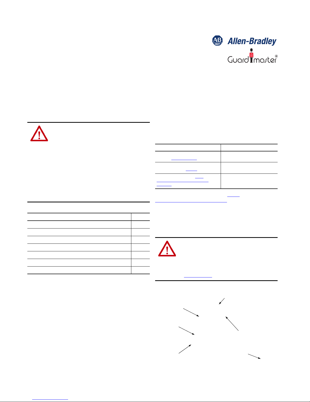
Locking b olt
Actu ator
Switch body
Actuator mounting
bracket
QR Code
Alignment
guide
Original Instructions
440G-LZ Guard Locking Safety Switch
Catalog Numbers
440G-LZS21SJLJ, 440G-LZS21SJRJ, 440G-LZS21SPLA, 440G-LZS21SPLB, 440G-LZS21SPLH, 440G-LZS21SPRA, 440G-LZS21SPRB,
440G-LZS21SPRH, 440G-LZS21STLA, 440G-LZS21STLB, 440G-LZS21STLH, 440G-LZS21STRA, 440G-LZS21STRB, 440G-LZS21STRH, 440G-LZS21UJLJ,
440G-LZS21UJRJ, 440G-LZS21UPLA, 440G-LZS21UPLB, 440G-LZS21UPLH, 440G-LZS21UPRA, 440G-LZS21UPRB, 440G-LZS21UPRH, 440G-LZS21UTLA,
440G-LZS21UTLB, 440G-LZS21UTLH, 440G-LZS21UTRA, 440G-LZS21UTRB, 440G-LZS21UTRH
Additional Resources
ATT EN TI ON : Read this document and the documents that are listed
in the Additional Resources section about installation,
configuration, and operation of this equipment before you install,
configure, operate, or maintain this product. Users are required to
familiarize themselves with installation and wiring instructions,
and requirements of all applicable codes, laws, and standards.
Activities including installation, adjustments, putting into service,
use, assembly, disassembly, and maintenance are required to be
carried out by suitably trained personnel in accordance with
applicable code of practice.
If this equipment is used in a manner not specified by the
manufacturer, the protection provided by the equipment may be
impaired.
Topi c Page
Summary of Changes 1
Additional Resources 1
Introduction 1
Mounting 2
Installation Considerations 2
Auxiliary/Manual Release 3
Connections 4
The QR code on the switch provides a link to publication
440G-UM001A-EN-P.
Resource Description
440G-LZ Guard Locking Switch User Manual,
publication 440G-UM001A-EN-P
Industrial Automation Wiring and Grounding
Guidelines, publication 1770-4.1
Product Certifications website, http://
www.rockwellautomation.com/products/
certification
You can view or download publications at http://
www.rockwellautomation.com/literature/. To order paper copies of
technical documentation, contact your local Allen-Bradley distributor
or Rockwell Automation sales representative.
Provides general guidelines for installing a
Rockwell Automation guard locking switch.
Provides general guidelines for installing a
Rockwell Automation industrial system.
Provides declarations of conformity,
certificates, and other certification details.
Introduction
ATT EN TI ON : Do not attempt to install this device unless the
installation instructions have b een studied and u nderstood. This
document acts as a guide for a typical installation and is available in
some languages at
Select the publication language and type 440G-LZ in the search
field. A user manual is also available, publication
440G-UM001A-EN-P
www.rockwellautomation.com/literature.
.
Summary of Changes
Added required minimum distance between switches and detail for 5pin quick-disconnect models.
Figure 1 - Assembly Overview
Page 2
440G-LZ Guard Locking Safety Switch
For proper installation, a
minimum of two fasteners
must be used, at least one of
which must be fitted to the top
row of holes, closest to the
bend in the actuator mounting
bracket.
2 x M5/M6 CSK
3 x M5
The locking bolt must always enter
the actuator mounting bracket first.
200 mm (7.87 in.) minimum
Align the white triangles
0.4 N•m
2 x T10
Torx screws
This 440G-LZ Guard Locking switch is for use on guards that are
engineered to be rigid without sag. A separately mounted latch (for
example, magnetic, mechanical) and mechanical stop is required.
Installation must be in accordance with these instructions and must be
carried out by qualified personnel.
ATT EN TI ON : After installation, ensu re that there is no p ossibility
of lifting the ac tuator over the extended locki ng bolt. Adherence to
the recommended maintenance instructions forms part of the
warr anty.
This device is intended to be part of the safety-related control system of
a machine. Before installation, a risk assessment must be performed to
determine whether the specifications of this de vice are suitable for all
foresee able ope rational and environmental characteristi cs of the
application. See Specifications on page 5
and ratings.
Use appropriate screws, bolts, or nuts that are fitted by tools to mount
the switch and actuators to avoid the risk of tampering. Do not over
torque the mounting hardware.
for certification information
Mounting
Figure 2 - Switch Body and Actuator
Installation Considerations
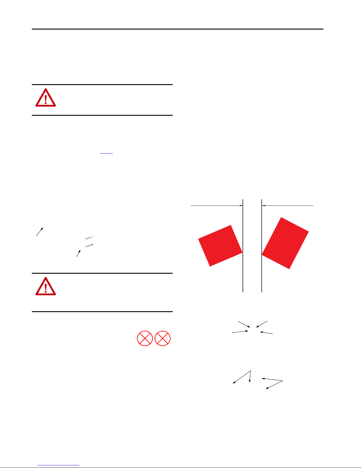
Figure 4 - Orientation of Assembled S
Minimum Distance Between Switches
If a pair of 440G-LZ switches is mounted close to each other, the two
inductive fields interact causing crosstalk, which results in nuisance
faults and false operation.
An absolute minimum of 200 mm (8 in.) must be used to help achieve
correct operation.
The restriction applies if a 440G-LZ switch is mounted close to the
TLS-Z guard locking and the 440N-Z SensaGuard™ switches.
Figure 5 - Minimum Distance between Switches
witch
ATT EN TI ON : For the switch, actuator and actuator mounting
bracket:
• Only use the designated mounting holes.
• Never drill or use to support other structures such as conduit,
cable wa ys, or other hardware.
Figure 3 - Actuator Mounting Possibilities
2 Rockwell Automation Publication 440G-IN011B-EN-P - October 2018
Figure 6 -
Four Directions of Approach
Page 3

440G-LZ Guard Locking Safety Switch
G
H
2.5 (0.098)
dia.
25
(0.98)
50
(1.97)
22.5
(0.89)
45 (1.77)
8
(0.31)
10
(0.39)
22.9
(0.90)
140 (5.51)
10
(0.39)
9.5
(0.37)
9.525
(0.37) dia.
22.5
(0.88)
134.5 (5.29)
33
(1.29)
2 x 5.5
(0.22) dia.
Figure 7 - Actuator Alignment (Three Methods)
1. By setting gap
2.5 mm (0.09 in.)
[
0…5 mm (0…0.19 in.)
2. By mounting hole alignment
H”
6.5 mm (0.25 in.)
“
[4…9 mm (0.15…0.35 in.)]
3. By use of the
Alignment
“G”
]
Guide
Auxiliary/Manual Release
Operation
To reset the switch, cycle the power.
Figure 8 - Manual Release Operation [mm (in.)]
Figure 9 - Dimensions [mm
of the
auxiliary release caus
(in.)]
es
a fault condition.
IMPORTANT It might be easier to achieve actuator alignment by first
mounting just the actuator mounting bracket to the guard/
door and then fit the actuator to its mounting bracket.
It is not possible to mechanically extend the locking bolt
during installation, this can only be done electrically (see
Commissioning in the user manual).
ATT EN TIO N: After installation, be sure that there is no possibility
of lifting the actuator over the extended locking bolt.
After installation, be sure that there is no possibility of collision
when the actuator approaches the switch body.
51.5 (2.03)
40 (1.57)
40
(1.57)
65
(2.56)
47
(1.85)
3
(0.12)
Act uato rs.
25.4
(1.0)
7
(0.28)
25 (0.98)
6 x 6.35
(0.25) dia.
12.5
(0.5)
See publication 440G-UM001, for configuring Unique
Rockwell Automation Publication 440G-IN011B-EN-P - October 2018 3
Page 4

440G-LZ Guard Locking Safety Switch
2 24V DC+
1 Aux
7 0V
6 Safety B
3 Lock Command
8 Safety A+
4 Safety B+
5 Safety A
Keyway
5
4
3
1
2
Connections
Figure 10 - Eight-pin Micro (M12) or Cable Version
Color Function Pin
White Aux 1
Brown 24V DC+ 2
Green Lock 3
Yel low Saf et y B+ 4
Grey Safety A 5
Pink Sa fety B 6
Blue Gnd/0V 7
Red Safety A+ 8
The recommended cordset is catalog number 889D-F8AB-2 (2 m
[6.5ft]). For additional lengths, replace the 2 with a 5 (5 m [16.4 ft]), or
10 m (32.8 ft) for standard cable lengths.
Five-pin Micro (M12)
Pin Color Function
1Brown+24
2 White Safety OSSD 1 Output
3Blue0V
4 Black Safety OSSD2 Output
5GrayLock Command
The recommended cordset is catalog number 889D-F5AC-2 (2 m
[6.5ft]). For additional lengths, replace the 2 with 5 [5 m (16.4 ft)] or
10 [10 m (32.8 ft)] for standard cable lengths.
The recommended patchcord for use with ArmorBlock® Guard Safety
I/O is the 2 m (6.5 ft) catalog number 889D-F5ACDM-2. Replace the
2 with 0M3 [0M3 (0.98 ft)], 1 [1 m (3.28 ft)], 5 [5 m (16.4 ft)], or 10
[10 m (32.8 ft)] for standard cable lengths.
4 Rockwell Automation Publication 440G-IN011B-EN-P - October 2018
Page 5

440G-LZ Guard Locking Safety Switch
Specifications
Standards
Safety classification: Guard door sensi ng
and lock monitoring
Functional Safety Data: G uard door sensing
and lock monitoring
Certifications
Operating Characteristics Protection class (IEC 61140) Class II
Torque for M5 mounting of switch and
actuator mounting bracket
Locking bolt insertion for assured locking
and holding force
Locking bolt alignment tolerance
X, Y, Z
Holding force Fmax (EN/ISO 14119) 1690 N Auxiliary outputs 1 x PNP, 0.2 A max / OFF (0V DC)
Holding force Fzh (EN/ISO 14119) 1300 N Environmental
Maximum output current (each outputs) 200 mA Operating temperature 0…55 °C (32…131 °F)
Quiescent power consumption, locked or
unlocked
Lock signal current 3.5 mA signal on green lock/unlock wire Operating humidity 5…95% relative
Peak current and duration, at turn on or
after lock/unlock operation
Operating voltage Ue 24V DC +10% / -15% Class 2 SELV Shock and vibration IEC 60068-2-27 30 g, 11 ms/IEC 60068-2-6 10…55 Hz
Maximum frequency of operating cycles 0.2 Hz Hygienic
Dwell time between subsequent locking/
unlocking
Response time (Off) 100 ms first switch, 50 ms additional for each switch Radio frequency / EMC IEC 60947-5-3, FCC-1(Parts 18&15), R&TTE
Risk time 100 ms (according to IEC 60947-5-3)
Start up time (availability) 5 s General
Maximum length of a chain of switches 10 km (Dependent on cable/connection/ required response time) Materials ABS, locking bolt and mounting bracket 304 stainless steel
Utilization category (IEC 60947-5-2) DC-13 24V 200 mA Weight switch/actuator Switch 400 g, actuator 150 g, actuator mounting bracket 60 g
Insulation voltage Ui (IEC 60947-1) 75V Protection Type
IEC 60947-5-3, IEC 60947-5-1, IEC 61508, EN ISO 13849-1, IEC
62061, ISO 14119, UL 508
PLe Category 4 per ISO 13849-1, SIL 3 per IEC 61508 and IEC 62061
-10
PFHd: 9.1 x 10
application up to PLe (according to ISO 13849-1) a nd for use up to
SIL3 systems (according to IEC 62061 and IEC 61508) depending on
application characteristics. Mission time/PTI: 20 years
CE Marked for all applicable EU directives, c-UL-us (UL 508), TÜV,
C-tick
2 N•m (17.7 lb•in) max Mechanical life 500,000 cycles
5 mm (0.19 in.) min, 10 mm (0.39 in.) max Outputs (Guard door closed and locked)
±2.5 mm (0.09 in.) max Safety outputs 2 x PNP, 0.2 A max / ON (+24V DC)
2.5 W Storage temperature -25…+75 °C (-13…+167 °F)
400 mA/100 ms Enclosure ingress rating NEMA 3, 4X, 12, 13, IP66, IP67, IP69K
2.5 s Washdown Sodium Hydroxide based washdown fluids
; Dual channel interlock can be suitable for use in
Operating Characteristics (continued)
Impulse withstand voltage Uimp
(IEC 60947-1)
Pollution degree (IEC 60947-1) 3
Manual (auxiliary) relea se Built in
1 kV
ISO 14159:2004 and EN 1672-2005, (for that part of the machine
defined as “food splash area”)
Short-circuit, current limitation, overload, reverse polarity,
overvoltage (up to 60V max.), thermal shutdown/restar t
Status/Diagnostic Operating LED Indicators
The switch has two pairs of LEDs. Status LEDs are green and diagnostic LEDs are red.
Power to Lock Versions Door/Guard Status Lock Com mand OSSD Input Lock Status LED Status OSSD Status
Power on and lock command off Open or closed Off Off or on Unlocked
Lock command on and door open Open On Off or on Unlocked Fast flash green Off
Lock command on and door closed Closed On Off Locked Slow flash green Off
Lock command on and door closed Closed On On Locked Solid green On
Power to Release Versions
Power on with door open Open Off Off or on Unlocked
Power on with door closed Closed Off Off Locked
Power on with door closed and OSSD
input active
Unlock command on and door closed or
open
Door/Guard
Status
Closed Off On Locked
Open or closed On Off or on Unlocked Solid red Off
Blinks 6 x green then
solid red
Off
Unlock Command OSSD Input Lock Status LED Status OSSD Status
Blinks 6 x green then 1 x blink red
followed by fast flash green
Blinks 6 x green then 1 x blink red
followed by slow flash green
Blinks 6 x green then 1 x blink red
followed by solid green
Off
Off
On
Rockwell Automation Publication 440G-IN011B-EN-P - October 2018 5
Page 6

Rockwell Otomasyon Ticaret A.Ş., Kar Plaza İş Merkezi E Blok Kat:6 34752 İçerenköy, İstanbul, Tel: +90 (216) 5698400
Catalog Numbers for Complete Switches
Rockwell Automation Support
Use the following resources to access support information.
Documentation Feedback
Your comments will help us serve your documentation needs better. If you have any suggestions on how to improve this document, complete the
How Are We Doing? form at http://literature.rockwellautomation.com/idc/groups/literature/documents/du/ra-du002_-en-e.pdf.
Technical Support Center
Knowledgebase Articles, How-to Videos, FAQs, Chat, User
Forums, and Product Notification Updates.
https://rockwellautomation.custhelp.com/
Local Technical Support Phone Numbers Locate the phone number for your country. http://ww w.rockwellautomation.com/global/support/get-suppor t-now.page
Direct Dial Codes
Find the Direct Dial Code for your product. Use the code to
route your call directly to a technical support engineer.
http://www.rockwellautomation.com/global/support/direct-dial.page
Literature Library
Installation Instructions, Manuals, Brochures, and
Technical Data.
http://www.rockwellautomation.com/global/literature-library/overview.page
Product Compatibility and Download
Center (PCDC)
Get help determining how products interact, check
features and capabilities, and find associated firmware.
http://www.rockwellautomation.com/global/support/pcdc.page
440G-LZS21
abcd
abcd
S Standard Coding J No Auxiliary (5-pin models) R Power-to-Release A 3 m Cable
U Unique Coding P Auxiliary—Lock Status L Power-to-Lock B 10 Cable
T Auxiliary—Door Proximity H M12 8-pin
J M12 5-pin
Waste Electrical and Electronic Equipment (WEEE)
At the end of life, this equipment should be collected separately
from any unsorted municipal waste.
Rockwell Automation maintains current product environmental information on its website at
http://www.rockwellautomation.com/rockwellautomation/about-us/sustainability-ethics/product-environmental-compliance.page
Allen-Bradley, ArmorBlock, Rockwell Automation, Rockwell Software, and SensaGuard are trademarks of Rockwell Automation, Inc.
Trademarks not belonging to Rockwell Automation are property of their respective companies.
.
Publication 440G-IN011B-EN-P - October 2018 PN-212379
Supersedes Publication 440G-IN011B-EN-P - June 2015 10000818284 Ver 04
Copyright © 2018 Rockwell Automation, Inc. All rights reserved. Printed in the U.S.A.
 Loading...