

Allen-Bradley 2711P-K4M5A8, 2711P-K4M20D8, 2711P-K4M5D8, 2711P-K4M20A8, 2711P-K4C5A8 User Manual
...Page 1

User Manual
Original Instructions
PanelView Plus 6 Terminals
Catalog Numbers 2711P-K4M5A8, 2711P-K4M5D8, 2711P-K4M20A8, 2711P-K4M20D8, 2711P-K4C5A8, 2711P-B4C5A8, 2711P-K4C5D8,
2711P-B4C5D8, 2711P-K4C20A8, 2711P-B4C20A8, 2711P-K4C20D8, 2711P-B4C20D8, 2711P-K6M5A8, 2711P-T6M5A8, 2711P-B6M5A8,
2711P-K6M5D8, 2711P-T6M5D8, 2711P-B6M5D8, 2711P-K6M20A8, 2711P-T6M20A8, 2711P-B6M20A8, 2711P-K6M20D8, 2711P-T6M20D8,
2711P-B6M20D8, 2711P-K6C5A8, 2711P-T6C5A8, 2711P-B6C5A8, 2711P-K6C5D8, 2711P-T6C5D8, 2711P-B6C5D8, 2711P-K6C20A8,
2711P-T6C20A8, 2711P-B6C20A8, 2711P-K6C20D8, 2711P-T6C20D8, 2711P-B6C20D8, 2711P-K6C5A9, 2711P-T6C5A9, 2711P-B6C5A9,
2711P-K6C5D9, 2711P-T6C5D9, 2711P-B6C5D9, 2711P-K6C20A9, 2711P-T6C20A9, 2711P-B6C20A9, 2711P-K6C20D9, 2711P-T6C20D9,
2711P-B6C20D9, 2711P-K7C4D8, 2711P-T7C4D8, 2711P-B7C4D8, 2711P-T7C4D8K, 2711P-K7C4A8, 2711P-T7C4A8, 2711P-B7C4A8,
2711P-K10C4D8, 2711P-T10C4D8, 2711P-B10C4D8, 2711P-K10C4A8, 2711P-T10C4A8, 2711P-B10C4A8, 2711P-K12C4D8, 2711P-T12C4D8,
2711P-B12C4D8, 2711P-T12C4D8K, 2711P-K12C4A8, 2711P-T12C4A8, 2711P-B12C4A8, 2711P-K15C4D8, 2711P-T15C4D8, 2711P-B15C4D8,
2711P-K15C4A8, 2711P-T15C4A8, 2711P-B15C4A8, 2711P-K7C4D9, 2711P-T7C4D9, 2711P-B7C4D9, 2711P-K7C4A9, 2711P-T7C4A9,
2711P-B7C4A9, 2711P-K10C4D9, 2711P-T10C4D9, 2711P-B10C4D9, 2711P-K10C4A9, 2711P-T10C4A9, 2711P-B10C4A9, 2711P-K12C4D9,
2711P-T12C4D9, 2711P-B12C4D9, 2711P-K12C4A9, 2711P-T12C4A9, 2711P-B12C4A9, 2711P-K15C4D9, 2711P-T15C4D9, 2711P-B15C4D9,
2711P-K15C4A9, 2711P-T15C4A9, 2711P-B15C4A9
Page 2
Important User Information
IMPORTANT
Read this document and the documents listed in the additional resources section about installation, configuration, and
operation of this equipment before you install, configure, operate, or maintain this product. Users are required to
familiarize themselves with installation and wiring instructions in addition to requirements of all applicable codes, laws,
and standards.
Activities including installation, adjustments, putting into service, use, assembly, disassembly, and maintenance are required
to be carried out by suitably trained personnel in accordance with applicable code of practice.
If this equipment is used in a manner not specified by the manufacturer, the protection provided by the equipment may be
impaired.
In no event will Rockwell Automation, Inc. be responsible or liable for indirect or consequential damages resulting from the
use or application of this equipment.
The examples and diagrams in this manual are included solely for illustrative purposes. Because of the many variables and
requirements associated with any particular installation, Rockwell Automation, Inc. cannot assume responsibility or
liability for actual use based on the examples and diagrams.
No patent liability is assumed by Rockwell Automation, Inc. with respect to use of information, circuits, equipment, or
software described in this manual.
Reproduction of the contents of this manual, in whole or in part, without written permission of Rockwell Automation,
Inc., is prohibited.
Throughout this manual, when necessary, we use notes to make you aware of safety considerations.
WARNING: Identifies information about practices or circumstances that can cause an explosion in a hazardous environment,
which may lead to personal injury or death, property damage, or economic loss.
ATTENTION: Identifies information about practices or circumstances that can lead to personal injury or death, property
damage, or economic loss. Attentions help you identify a hazard, avoid a hazard, and recognize the consequence.
Identifies information that is critical for successful application and understanding of the product.
Labels may also be on or inside the equipment to provide specific precautions.
SHOCK HAZARD: Labels may be on or inside the equipment, for example, a drive or motor, to alert people that dangerous
voltage may be present.
BURN HAZARD: Labels may be on or inside the equipment, for example, a drive or motor, to alert people that surfaces may
reach dangerous temperatures.
ARC FLASH HAZARD: Labels may be on or inside the equipment, for example, a motor control center, to alert people to
potential Arc Flash. Arc Flash will cause severe injury or death. Wear proper Personal Protective Equipment (PPE). Follow ALL
Regulatory requirements for safe work practices and for Personal Protective Equipment (PPE).
Page 3

Summary of Changes
This manual contains new and updated information. Changes throughout this
revision are marked by change bars, as shown to the right of this paragraph.
New and Updated Information
This table contains the changes made to this revision.
Top ic Pag es
Added information about free user memory available for PanelView Plus 6
terminals.
17, and 20…23
Rockwell Automation Publication 2711P-UM006E-EN-P - January 2017 3
Page 4

Summary of Changes
Notes:
4 Rockwell Automation Publication 2711P-UM006E-EN-P - January 2017
Page 5

Table of Contents
Preface
Overview
Install Terminal
Additional Resources . . . . . . . . . . . . . . . . . . . . . . . . . . . . . . . . . . . . . . . . . . . . . . . 9
Package Contents . . . . . . . . . . . . . . . . . . . . . . . . . . . . . . . . . . . . . . . . . . . . . . . . . . 9
Firmware Upgrades . . . . . . . . . . . . . . . . . . . . . . . . . . . . . . . . . . . . . . . . . . . . . . . . 9
Chapter 1
About the Terminals . . . . . . . . . . . . . . . . . . . . . . . . . . . . . . . . . . . . . . . . . . . . . 11
Windows CE Operating System. . . . . . . . . . . . . . . . . . . . . . . . . . . . . . . . . . . 12
Open versus Closed System . . . . . . . . . . . . . . . . . . . . . . . . . . . . . . . . . . . . . . . 12
Start-up Options . . . . . . . . . . . . . . . . . . . . . . . . . . . . . . . . . . . . . . . . . . . . . . . . . 13
Desktop Access . . . . . . . . . . . . . . . . . . . . . . . . . . . . . . . . . . . . . . . . . . . . . . . . . . 13
Software Support . . . . . . . . . . . . . . . . . . . . . . . . . . . . . . . . . . . . . . . . . . . . . . . . 13
400 and 600 Terminal Features . . . . . . . . . . . . . . . . . . . . . . . . . . . . . . . . . . . 14
700 to 1500 Terminal Features. . . . . . . . . . . . . . . . . . . . . . . . . . . . . . . . . . . . 17
400/600 Terminal Selections . . . . . . . . . . . . . . . . . . . . . . . . . . . . . . . . . . . . . 20
700 to 1500 Terminal Selections . . . . . . . . . . . . . . . . . . . . . . . . . . . . . . . . . . 21
Accessories . . . . . . . . . . . . . . . . . . . . . . . . . . . . . . . . . . . . . . . . . . . . . . . . . . . . . . 22
Chapter 2
Mounting Clearances. . . . . . . . . . . . . . . . . . . . . . . . . . . . . . . . . . . . . . . . . . . . . 30
Panel Guidelines . . . . . . . . . . . . . . . . . . . . . . . . . . . . . . . . . . . . . . . . . . . . . . . . . 30
Panel Cutout Dimensions . . . . . . . . . . . . . . . . . . . . . . . . . . . . . . . . . . . . . . . . 30
Product Dimensions . . . . . . . . . . . . . . . . . . . . . . . . . . . . . . . . . . . . . . . . . . . . . 31
Mount the 400/600 Terminal in a Panel . . . . . . . . . . . . . . . . . . . . . . . . . . . 33
Mount the 700 to 1500 Terminal in a Panel . . . . . . . . . . . . . . . . . . . . . . . . 35
Remove and Install the Power Terminal Block. . . . . . . . . . . . . . . . . . . . . . 37
DC Power Connections . . . . . . . . . . . . . . . . . . . . . . . . . . . . . . . . . . . . . . . . . . 38
AC Power Connections . . . . . . . . . . . . . . . . . . . . . . . . . . . . . . . . . . . . . . . . . . 41
Initial Startup. . . . . . . . . . . . . . . . . . . . . . . . . . . . . . . . . . . . . . . . . . . . . . . . . . . . 43
Reset the Terminal . . . . . . . . . . . . . . . . . . . . . . . . . . . . . . . . . . . . . . . . . . . . . . . 43
Configuration Mode
Chapter 3
Access Configuration Mode. . . . . . . . . . . . . . . . . . . . . . . . . . . . . . . . . . . . . . . 45
Terminal Settings . . . . . . . . . . . . . . . . . . . . . . . . . . . . . . . . . . . . . . . . . . . . . . . . 48
Load and Run Application . . . . . . . . . . . . . . . . . . . . . . . . . . . . . . . . . . . . . . . . 50
Start-up Options . . . . . . . . . . . . . . . . . . . . . . . . . . . . . . . . . . . . . . . . . . . . . . . . . 51
Desktop Access . . . . . . . . . . . . . . . . . . . . . . . . . . . . . . . . . . . . . . . . . . . . . . . . . . 54
Communication Setup . . . . . . . . . . . . . . . . . . . . . . . . . . . . . . . . . . . . . . . . . . . 58
Ethernet Network Connections . . . . . . . . . . . . . . . . . . . . . . . . . . . . . . . . . . . 60
File Management. . . . . . . . . . . . . . . . . . . . . . . . . . . . . . . . . . . . . . . . . . . . . . . . . 64
Display Settings . . . . . . . . . . . . . . . . . . . . . . . . . . . . . . . . . . . . . . . . . . . . . . . . . . 67
Input Device Settings. . . . . . . . . . . . . . . . . . . . . . . . . . . . . . . . . . . . . . . . . . . . . 69
Configure Print Options . . . . . . . . . . . . . . . . . . . . . . . . . . . . . . . . . . . . . . . . . 72
Check Integrity of Application Files . . . . . . . . . . . . . . . . . . . . . . . . . . . . . . . 74
Configure Diagnostics. . . . . . . . . . . . . . . . . . . . . . . . . . . . . . . . . . . . . . . . . . . . 75
Rockwell Automation Publication 2711P-UM006E-EN-P - January 2017 5
Page 6

Table of Contents
Windows CE Operating System
View and Clear the System Event Log . . . . . . . . . . . . . . . . . . . . . . . . . . . . . . 76
System Information . . . . . . . . . . . . . . . . . . . . . . . . . . . . . . . . . . . . . . . . . . . . . . 76
Enable or Disable the Alarm Display . . . . . . . . . . . . . . . . . . . . . . . . . . . . . . . 78
Time and Date Settings . . . . . . . . . . . . . . . . . . . . . . . . . . . . . . . . . . . . . . . . . . . 79
Regional Settings . . . . . . . . . . . . . . . . . . . . . . . . . . . . . . . . . . . . . . . . . . . . . . . . . 81
Font Linking. . . . . . . . . . . . . . . . . . . . . . . . . . . . . . . . . . . . . . . . . . . . . . . . . . . . . 84
Chapter 4
Windows CE 6.0 Standard Features. . . . . . . . . . . . . . . . . . . . . . . . . . . . . . . . 85
Windows CE 6.0 with Extended Features . . . . . . . . . . . . . . . . . . . . . . . . . . 87
Windows Explorer . . . . . . . . . . . . . . . . . . . . . . . . . . . . . . . . . . . . . . . . . . . . . . . 88
Taskbar. . . . . . . . . . . . . . . . . . . . . . . . . . . . . . . . . . . . . . . . . . . . . . . . . . . . . . . . . . 88
Input Panels . . . . . . . . . . . . . . . . . . . . . . . . . . . . . . . . . . . . . . . . . . . . . . . . . . . . . 88
Windows Control Panel . . . . . . . . . . . . . . . . . . . . . . . . . . . . . . . . . . . . . . . . . . 89
Backup and Restore. . . . . . . . . . . . . . . . . . . . . . . . . . . . . . . . . . . . . . . . . . . . . . . 90
Hardware Monitor . . . . . . . . . . . . . . . . . . . . . . . . . . . . . . . . . . . . . . . . . . . . . . . 93
Keypad Properties . . . . . . . . . . . . . . . . . . . . . . . . . . . . . . . . . . . . . . . . . . . . . . . . 95
Touch Properties. . . . . . . . . . . . . . . . . . . . . . . . . . . . . . . . . . . . . . . . . . . . . . . . . 95
Display Properties . . . . . . . . . . . . . . . . . . . . . . . . . . . . . . . . . . . . . . . . . . . . . . . . 96
Logo Manager. . . . . . . . . . . . . . . . . . . . . . . . . . . . . . . . . . . . . . . . . . . . . . . . . . . . 98
System Information . . . . . . . . . . . . . . . . . . . . . . . . . . . . . . . . . . . . . . . . . . . . . . 99
User Accounts . . . . . . . . . . . . . . . . . . . . . . . . . . . . . . . . . . . . . . . . . . . . . . . . . . 102
Services . . . . . . . . . . . . . . . . . . . . . . . . . . . . . . . . . . . . . . . . . . . . . . . . . . . . . . . . . 103
Network Server Configuration . . . . . . . . . . . . . . . . . . . . . . . . . . . . . . . . . . . 104
Printer Support . . . . . . . . . . . . . . . . . . . . . . . . . . . . . . . . . . . . . . . . . . . . . . . . . 113
PDF Reader. . . . . . . . . . . . . . . . . . . . . . . . . . . . . . . . . . . . . . . . . . . . . . . . . . . . . 116
Image Viewer . . . . . . . . . . . . . . . . . . . . . . . . . . . . . . . . . . . . . . . . . . . . . . . . . . . 117
Chapter 5
Install and Replace Components
Required Tools. . . . . . . . . . . . . . . . . . . . . . . . . . . . . . . . . . . . . . . . . . . . . . . . . . 119
Install or Replace the Logic Module . . . . . . . . . . . . . . . . . . . . . . . . . . . . . . . 120
Install or Replace a Communication Module . . . . . . . . . . . . . . . . . . . . . . 121
Replace the Display Module . . . . . . . . . . . . . . . . . . . . . . . . . . . . . . . . . . . . . . 123
Replace the Bezel . . . . . . . . . . . . . . . . . . . . . . . . . . . . . . . . . . . . . . . . . . . . . . . . 124
Replace the Backlight . . . . . . . . . . . . . . . . . . . . . . . . . . . . . . . . . . . . . . . . . . . . 126
Replace the Battery . . . . . . . . . . . . . . . . . . . . . . . . . . . . . . . . . . . . . . . . . . . . . . 130
Install the AC Power Supply Module . . . . . . . . . . . . . . . . . . . . . . . . . . . . . 132
Remove the Product ID Label . . . . . . . . . . . . . . . . . . . . . . . . . . . . . . . . . . . . 134
Replace the Keypad Legend Inserts. . . . . . . . . . . . . . . . . . . . . . . . . . . . . . . . 134
Load an SD Card. . . . . . . . . . . . . . . . . . . . . . . . . . . . . . . . . . . . . . . . . . . . . . . . 136
Clean the Display . . . . . . . . . . . . . . . . . . . . . . . . . . . . . . . . . . . . . . . . . . . . . . . 137
Chapter 6
Terminal Connections
6 Rockwell Automation Publication 2711P-UM006E-EN-P - January 2017
USB Ports . . . . . . . . . . . . . . . . . . . . . . . . . . . . . . . . . . . . . . . . . . . . . . . . . . . . . . 140
Ethernet Connections . . . . . . . . . . . . . . . . . . . . . . . . . . . . . . . . . . . . . . . . . . . 142
Serial Connections . . . . . . . . . . . . . . . . . . . . . . . . . . . . . . . . . . . . . . . . . . . . . . 144
Page 7

Firmware Upgrades
Table of Contents
DH-485/DH+ Communication Module . . . . . . . . . . . . . . . . . . . . . . . . . 147
ControlNet Communication Module . . . . . . . . . . . . . . . . . . . . . . . . . . . . 150
Controller Connections . . . . . . . . . . . . . . . . . . . . . . . . . . . . . . . . . . . . . . . . . 153
Chapter 7
Terminal Firmware . . . . . . . . . . . . . . . . . . . . . . . . . . . . . . . . . . . . . . . . . . . . . 155
Download Firmware Files. . . . . . . . . . . . . . . . . . . . . . . . . . . . . . . . . . . . . . . . 156
Firmware Upgrade Wizard. . . . . . . . . . . . . . . . . . . . . . . . . . . . . . . . . . . . . . . 156
Upgrade Terminal Firmware from a Storage Device. . . . . . . . . . . . . . . . 157
Upgrade Terminal Firmware over the Network. . . . . . . . . . . . . . . . . . . . 160
Chapter 8
Troubleshooting
Fonts Resident on Terminal
Outdoor Installations for High-bright
Displays
Index
Status Indicators . . . . . . . . . . . . . . . . . . . . . . . . . . . . . . . . . . . . . . . . . . . . . . . . 163
Terminal Does Not Start Properly. . . . . . . . . . . . . . . . . . . . . . . . . . . . . . . . 164
Start-up Messages and Codes. . . . . . . . . . . . . . . . . . . . . . . . . . . . . . . . . . . . . 166
Check Terminal Components . . . . . . . . . . . . . . . . . . . . . . . . . . . . . . . . . . . 168
Ethernet Connection. . . . . . . . . . . . . . . . . . . . . . . . . . . . . . . . . . . . . . . . . . . . 169
Program Launcher ActiveX Control . . . . . . . . . . . . . . . . . . . . . . . . . . . . . . 170
Application Does Not Run . . . . . . . . . . . . . . . . . . . . . . . . . . . . . . . . . . . . . . 170
Configuration Mode Access. . . . . . . . . . . . . . . . . . . . . . . . . . . . . . . . . . . . . . 170
File System Errors . . . . . . . . . . . . . . . . . . . . . . . . . . . . . . . . . . . . . . . . . . . . . . . 171
Advanced Diagnostics . . . . . . . . . . . . . . . . . . . . . . . . . . . . . . . . . . . . . . . . . . . 171
Access Maintenance Operations. . . . . . . . . . . . . . . . . . . . . . . . . . . . . . . . . . 172
Restore Factory Defaults. . . . . . . . . . . . . . . . . . . . . . . . . . . . . . . . . . . . . . . . . 174
Appendix A
True Type Fonts . . . . . . . . . . . . . . . . . . . . . . . . . . . . . . . . . . . . . . . . . . . . . . . . 177
Appendix B
Important Considerations . . . . . . . . . . . . . . . . . . . . . . . . . . . . . . . . . . . . . . . 179
Using an Antiglare Overlay . . . . . . . . . . . . . . . . . . . . . . . . . . . . . . . . . . . . . . 179
Using a Solar Visor . . . . . . . . . . . . . . . . . . . . . . . . . . . . . . . . . . . . . . . . . . . . . . 179
Selecting an Enclosure . . . . . . . . . . . . . . . . . . . . . . . . . . . . . . . . . . . . . . . . . . . 180
Backlight Considerations . . . . . . . . . . . . . . . . . . . . . . . . . . . . . . . . . . . . . . . . 180
Orientation of the Terminal . . . . . . . . . . . . . . . . . . . . . . . . . . . . . . . . . . . . . 180
Rockwell Automation Publication 2711P-UM006E-EN-P - January 2017 7
Page 8

Table of Contents
Notes:
8 Rockwell Automation Publication 2711P-UM006E-EN-P - January 2017
Page 9

Preface
This manual describes how to install, configure, operate, and troubleshoot
PanelView Plus 6 terminals. It does not provide procedures on how to create
applications that run on the terminal.
You need to do the following:
• Use FactoryTalk
HMI application to run in the terminal.
• Create ladder logic to interact with the HMI application.
®
View Studio for Machine Edition software to create an
Additional Resources
Package Contents
These documents contain additional information concerning related products
from Rockwell Automation.
Resource Description
PanelView Plus Specifications Technical Data, publication
2711P-TD005
Industrial Automation Wiring and Grounding Guidelines,
publication 1770-4.1
Product Certifications website, http://www.ab.com
Provides technical specifications, environmental
specifications, and certifications for the PanelView Plus 6
platform.
Provides general guidelines for installing a Rockwell
Automation® industrial system.
Provides declarations of conformity, certific ates, and other
certification details.
You can view or download publications at
http://www.rockwellautomation.com/literature/
. To order paper copies of
technical documentation, contact your local Allen-Bradley distributor or
Rockwell Automation sales representative.
This product is shipped with the following items:
• Terminal with FactoryTalk View Machine Edition runtime software
installed and activated
• Product information
• Mounting levers for installing 400 and 600 terminals
• Mounting clips for installing 700 to 1500 terminals
• Panel cutout template
Firmware Upgrades
For the latest firmware upgrades and other downloads for PanelView Plus 6
terminals, go to http://www.rockwellautomation.com/support
and click
Firmware Updates.
Rockwell Automation Publication 2711P-UM006E-EN-P - January 2017 9
Page 10

Preface
Notes:
10 Rockwell Automation Publication 2711P-UM006E-EN-P - January 2017
Page 11

Overview
Top ic Pa ge
Windows CE Operating System 12
Open versus Closed System 12
Desktop Access 13
Software Support 13
400 and 600 Terminal Features 14
700 to 1500 Terminal Features 17
400/600 Terminal Selections 20
700 to 1500 Terminal Selections 21
Accesso ries 22
Chapter 1
About the Terminals
PanelView Plus 6 terminals are operator interface devices that run HMI
machine-level applications in an industrial environment. The displays range in
size from 4 to 15 inches. These devices are used to monitor, control, or display
information graphically, letting operators quickly understand the status of their
application.
This platform is programmed by using common development software that
provides multilingual support, and integrates into systems with Rockwell
Automation controllers including preferred Logix controllers.
Rockwell Automation Publication 2711P-UM006E-EN-P - January 2017 11
Page 12
Chapter 1 Overview
Windows CE Operating System
PanelView Plus 6 terminals run the Windows CE operating system (OS),
providing the foundational OS elements for the majority of user needs.
For users with more complex application requirements, some of the terminals
offer optional, extended features and file viewers.
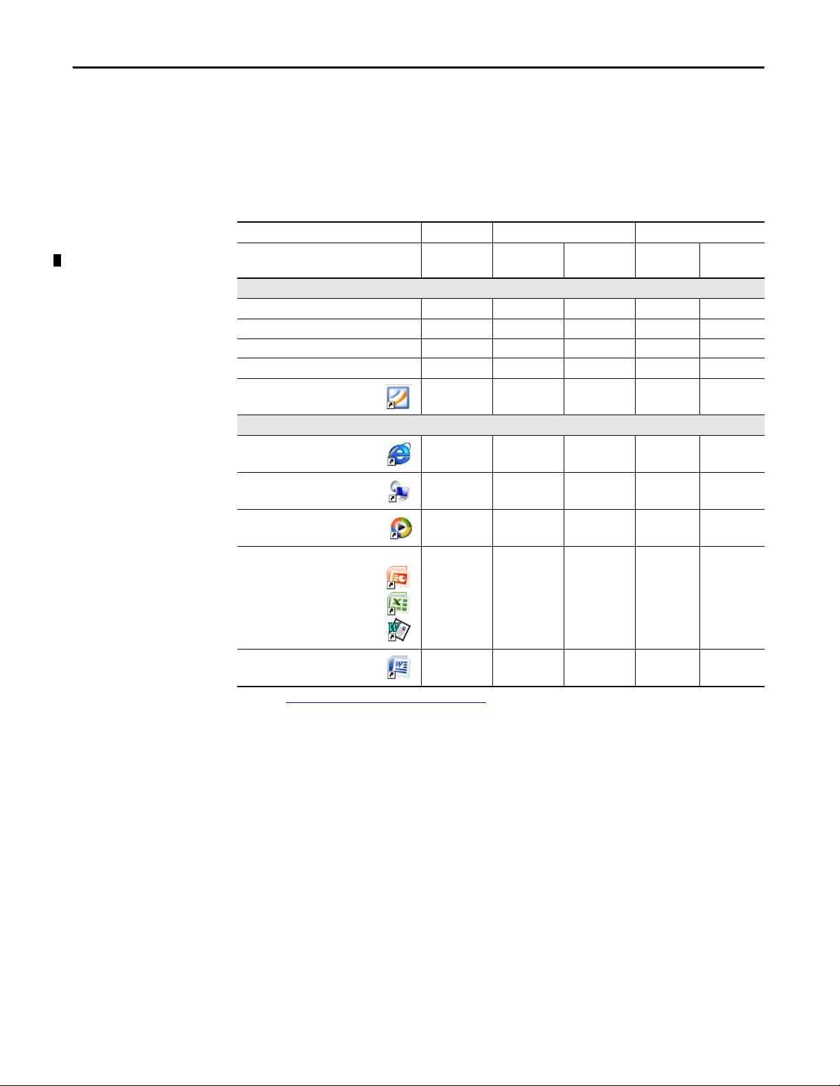
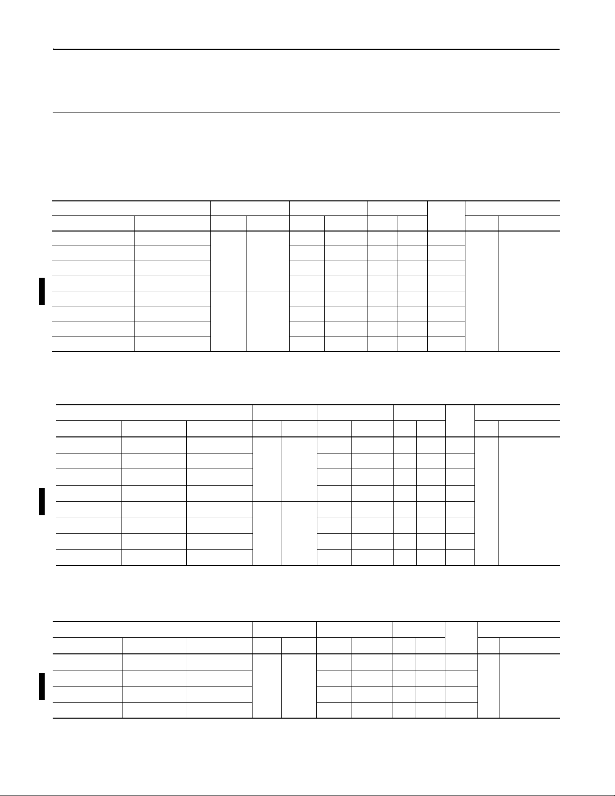
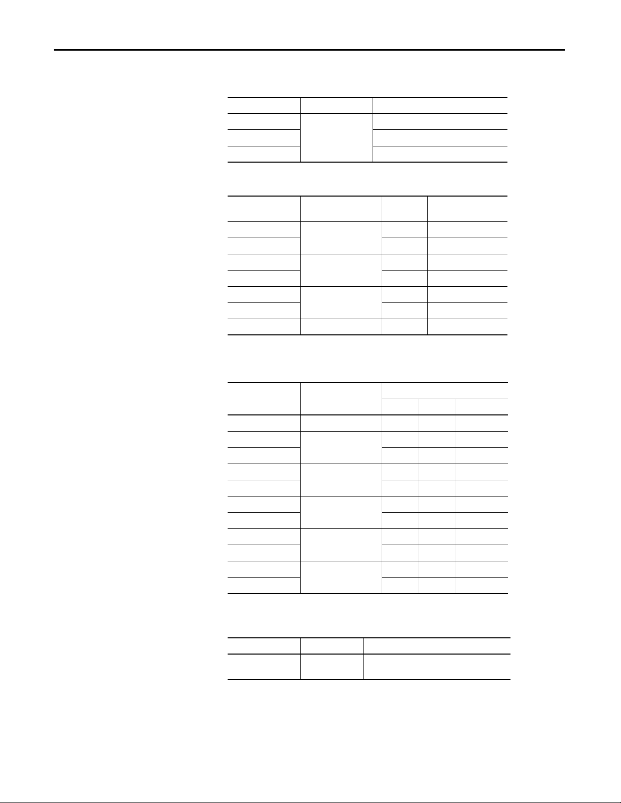
Table 1 - Operating System Features
Features 400 Terminals 600 Terminals 700 to 1500 Terminals
(2)
2711P-xxxx8
2711P-RP8x
—x
Cat. No. 2711P-xxxx8 2711P-xxxx8 2711P-xxxx9
Standard Features
FTP server x x x x x
VNC client/server x x x x x
ActiveX co ntrols
Third-party device support x x x x x
PDF reader x x x x x
Optional Extended Features
Web browser - Internet Explorer
Remote desktop connection
(1)
xxxxx
—— x—x
—— x
2711P-xxxx9
2711P-RP9x
Media player
Microsoft Office file viewers
• Power Point
• Excel
• Word
WordPad text editor — — x — x
(1) Refer to Display Factor yTal k View ME Station Inform ation on page 78 for a list of ActiveX controls loaded on a terminal.
(2) The remote desktop connection is not currently supported on PanelView Plus 6 - 600 terminals with extended features.
Open versus Closed System
—— x—x
—
—
—
—
—
—
x
x
x
—
—
—
x
x
x
The terminals can be configured to run an open or closed desktop environment:
• An open system launches the Windows Explorer desktop on startup. The
system is configurable via the control panel and supports Windows
operations.
• A closed system launches a FactoryTalk View Machine Edition application
on startup and restricts access to the Windows Explorer desktop.
All terminals are shipped as closed systems restricting access to the desktop. The
first time you start the system, the terminal launches FactoryTalk View ME
Station Configuration mode. At this point, you can change the start-up option
and allow desktop access.
12 Rockwell Automation Publication 2711P-UM006E-EN-P - January 2017
Page 13

Overview Chapter 1
TIP
IMPORTANT
Start-up Options
Desktop Access
You can configure the terminal to perform one of three actions at startup:
• Launch a FactoryTalk View Machine Edition HMI application.
• Launch the FactoryTalk View Machine Edition Configuration mode of
the terminal where you load and run applications, configure start-up
options and terminal settings, and enable or disable desktop access.
• Launch the Windows Explorer desktop.
The factory default state and start-up option following a firmware upgrade is to
launch the terminal in Configuration mode. Refer to Start-up Options on
page 51 for details on how to change the start-up option.
Any of the terminals can be configured to allow or restrict desktop access. From
the desktop, you can perform system and control panel operations, or run
third-party applications. Terminals with optional, extended features (catalog
numbers ending in 9) can additionally run viewers, media players, and launch the
web browser. You can even allow access temporarily to perform specific tasks,
then disable desktop access to prevent unauthorized changes.
All terminals are initially shipped with desktop access disabled.
Refer toDesktop Access on page 54
for details on how to modify desktop access.
Desktop access does not change the feature set of your terminal. If you have a
terminal with a catalog number ending in 8, opening the desktop does not
give you access to extended features and file viewers.
Software Support
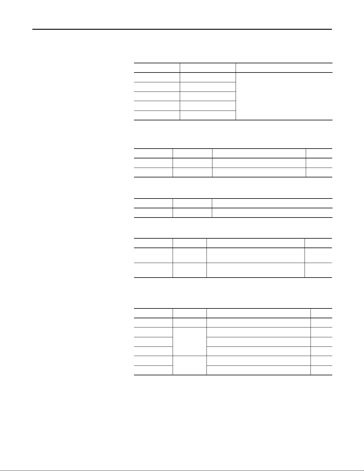
Table 2 - PanelView Plus 6 Software Support
Software Description Version
FactoryTalk View Machine Edition Station Runtime environment for FactoryTalk View Machine Edition .mer applications. Machine Edition
FactoryTalk View Studio for
Machine Edition
FactoryTalk ViewPoint
(700 to 1500 terminals only)
Windows CE 6.0 OS Operating system that runs on all terminals. 6.0
Station is preloaded on each terminal and does not require FactoryTalk View activation.
Configuration software for developing HMI applications that run on PanelView Plus 6 terminals.
RSLinx® Enterprise software is included with FactoryTalk View Studio software and loaded during
installation.
Add-on capability provided with FactoryTalk View Studio software:
• This web-based, thin-client solution lets manufacturers or casual users monitor or download
changes to a running Machine Edition application from remote locations via an Internet
browser.
• A single license is embedded with each terminal supporting a single client connection to
terminal. No additional software is required.
The table lists software supported on the terminals.
• 6.10 or later
• 6.0 or later
1.2 or later
(400 and 600 terminals)
(700 to 1500 terminals)
Rockwell Automation Publication 2711P-UM006E-EN-P - January 2017 13
Page 14
Chapter 1 Overview
5
7
8
9
10
12
11
6
3a
2
3b
4
1
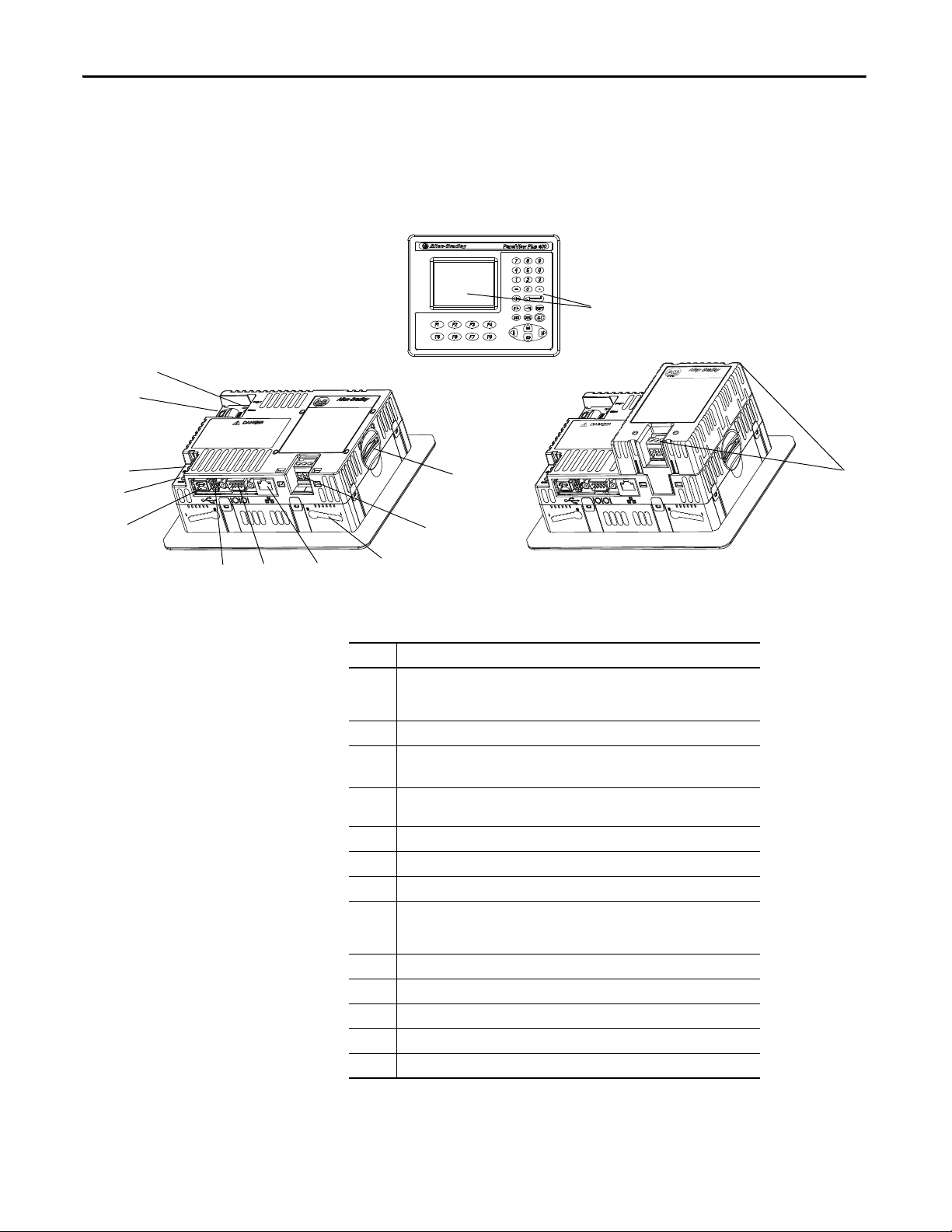
400 and 600 Terminal Features
Both the 400 and 600 terminals provide these communication options:
• RS-232 serial port only or
• Ethernet port and RS-232 serial port
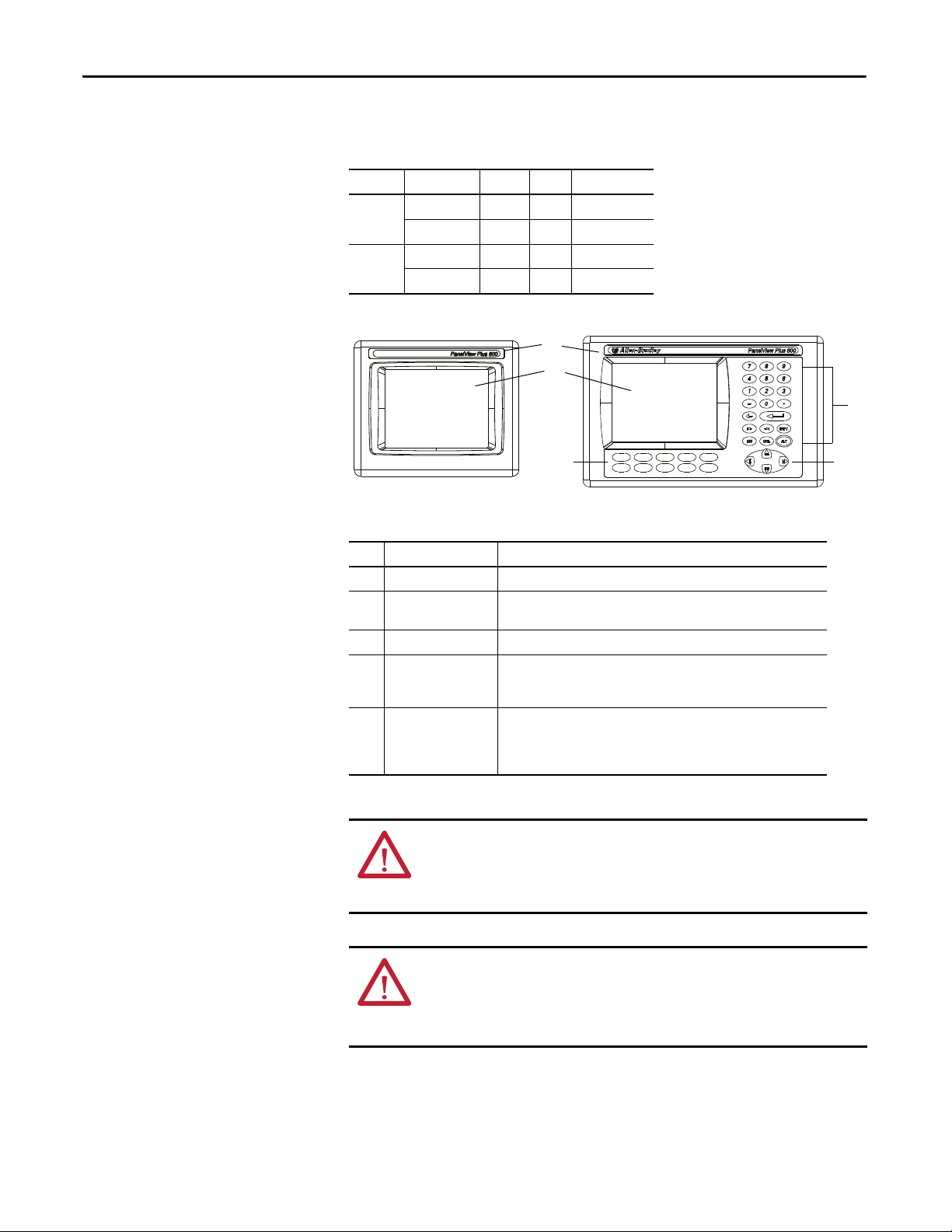
Figure 1 - 400 Keypad or Keypad/Touch Terminals
Table 3 - PanelView Plus 6 - 400 Terminal Components
Item Component
1 3.5-in. grayscale or color display with one of these operator input options:
• Keypad
• Combination keypad and touch screen
2 Secure Digital (SD) card slot supporting cat. no. 1784-SDx cards
3a DC power input, nonisolated
24V DC nom (18…30V DC)
3b AC power supply module with AC power input
100…240V AC (50…60 Hz)
4 Mounting slots (four)
5 Ethernet port for controller communi cation, 10/100Base-T, Auto MDI/MDI-X
6 RS-232 serial port for controller communication, printing, or file transfers
7 One USB 2.0 high-speed (type A) host port for attaching USB peripherals including
mouse, keyboard, printer, and USB drives that are hot-swappable in nonhazardous
locations
8 One USB 2.0 high-speed (type B) device port for connecting a host computer
9 Reset switch to reset the terminal without having to power off and on
10 Default switch to access maintenance operations such as restoring factory defaults
11 Battery compartment
12 Indicators provide communication and fault status
(1)
(1)
(2)
14 Rockwell Automation Publication 2711P-UM006E-EN-P - January 2017
(1) Presence of a DC power input or AC power supply module is catalog number dependent. Removing the
AC power supply module voids the terminal warranty.
(2) Presence of Ethernet port is catalog number dependent.
Page 15
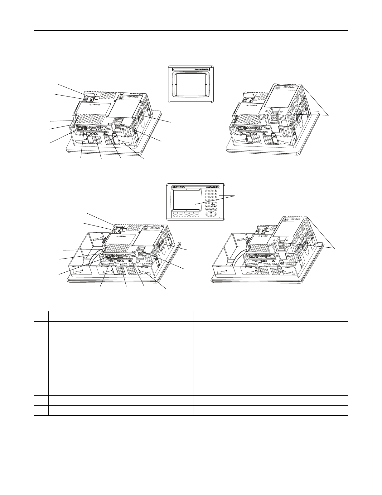
Figure 2 - 600 Touch Terminals
8
9
10
12
11
5
7
6
3a
2
4
3b
1a
8
9
10
12
11
7
5
6
3a
2
4
3b
1b
Figure 3 - 600 Keypad or Keypad/Touch Terminals
Overview Chapter 1
F1
F4F3 F5
F2
F6
F9F8 F10
F7
Table 4 - PanelView Plus 6 - 600 Terminal Components
Item Component Item Component
1a 5.7-in. color or grayscale display with a touch screen 6 RS-232 serial port for controller communication, printing, or file transfers
1b 5.7-in. color or grayscale display with either a:
• Keypad
• Combination keypad and touch screen
2 Secure Digital (SD) card slot supporting cat. no. 1784-SDx cards 8 One USB 2.0 high-speed (type B) device port for connecting a host computer
3a DC power input, nonisolated
(1)
24V DC nom (18…30V DC)
3b AC power supply module with AC power input
(1)
100…240V AC (50…60 Hz)
4 Mounting slots (four on touch terminals; six on keypad terminals) 11 Battery compartment
5 Ethernet port for controller communication, 10/100Base-T, Auto MDI/MDI-X
(1) Presence of a DC power input or the AC power supply module is catalog number dependent. Removing the AC power supply module voids the terminal warranty.
(2) Presence of Ethernet port is catalog number dependent.
7 One USB 2.0 high-speed (type A) host port for attaching USB peripherals
including mouse, keyboard, printer, and USB drives that are hot-swappable in
nonhazardous locations
9 Reset switch to reset the terminal without having to power off and on
10 Default switch to access maintenance operations such as restoring factory
defaults
(2)
12 Indicators provide communication and fault status
Rockwell Automation Publication 2711P-UM006E-EN-P - January 2017 15
Page 16
Chapter 1 Overview
F1
F2
F4F3 F5
F6
F7
F9F8 F10
1
2
3
4
5
The terminals feature grayscale or color LCD displays with these input options.
Table 5 - Operator Input Options
Terminal Display Type Keypad Touch Key and Touch
400 Grayscale •
Color • •
600 Grayscale • • •
Color • • •
Table 6 - Display and Operator Input Features
Item Feature Description
1 Product label Product identification label can be replaced with custom label.
2 Display/touch screen Color or grayscale display with or without a resistive, 4-wire, touch screen
(catalog number dependent)
3 Numeric keypad 0…9, Backspace, Enter, Left and Right Tab, Esc, Shift, Ctrl, Alt keys
4 Navigation keys Use arrow keys for navigation. Use Alt+arrow to initiate these functions:
• Alt+left arrow (Home), Alt+right arrow (End)
• Alt+up arrow (Page Up), Alt+down arrow (Page Down)
5Function keys
Keys that can be configured in the application to per form operations. For
example, F1 can be configured to navigate to another screen.
400
• F1…F8
600
• F1…F10
ATT EN TI ON : Use a finger or gloved finger to operate the keypad. To operate the
touch screen, use a finger, gloved-finger or plastic stylus with a minimum tip
radius of 1.3 mm (0.051 in.). Using any other object or tool can damage the
keypad or touch screen.
ATT EN TI ON : Do not carry out multiple operations simultaneously. Doing so can
result in unintended operation:
• Touch only one operating element on the screen with one finger at one time.
• Press only one key on the terminal at one time.
16 Rockwell Automation Publication 2711P-UM006E-EN-P - January 2017
Page 17
Overview Chapter 1
1
2
3
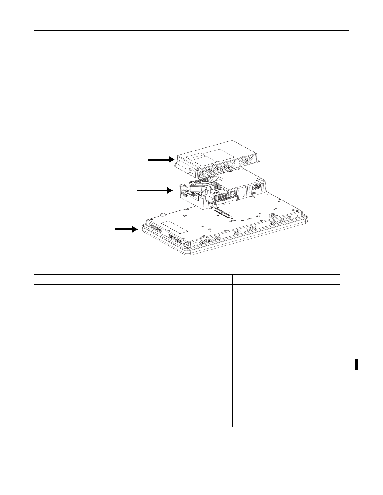
700 to 1500 Terminal Features
The larger 700 to 1500 terminals consist of modular components ordered
separately or as configured terminals. The modular components consist of the
following:
• Display module
• Logic module
• Optional communication module
These components provide for flexible configuration, installation, and upgrades.
You can order a factory-assembled unit with a single catalog number or separate
components for field installation.
Table 7 - Modular Components
Item Terminal Component Description Options for Environmental Conditions
1 Display module Flat panel, color graphic display in four sizes with keypad,
2 Logic module The logic module has these hardware features:
3 Communication module Optional module for communication with these networks:
touch-screen, or combination keypad/touch-screen input:
• 700 (6.5-in.)
• 1000 (10.4-in.)
• 1250 (12.1-in.)
• 1500 (15-in.)
• Power i nput, AC or DC
• RS-232 serial port
• Ethernet port
• 2 USB 2.0 host ports
• Network interface for optional communication module
• 512 MB RAM memory and 512 MB nonvolatile memory
(approx. 79 MB free user memory)
• Secure Digital (SD) card slot
• Battery-backed real-time clock
• Status indicators
• Reset switches
• Single PCI slot
• DH+
™/DH-485
• ControlNet scheduled and unscheduled
• Ethernet
Display modules are also available with these
characteristics:
• Marine-certified
• Conformal-coated
• High-bright display for outdoor use
• Built-in antiglare overlay
Logic modules are also available with these characteristics:
• Marine-certified
• Conformal-coated
Communication modules are also available with these
characteristics:
• Marine-certified
• Conformal-coated
Rockwell Automation Publication 2711P-UM006E-EN-P - January 2017 17
Page 18
Chapter 1 Overview
1
2
3
4
5
6
7
9
8
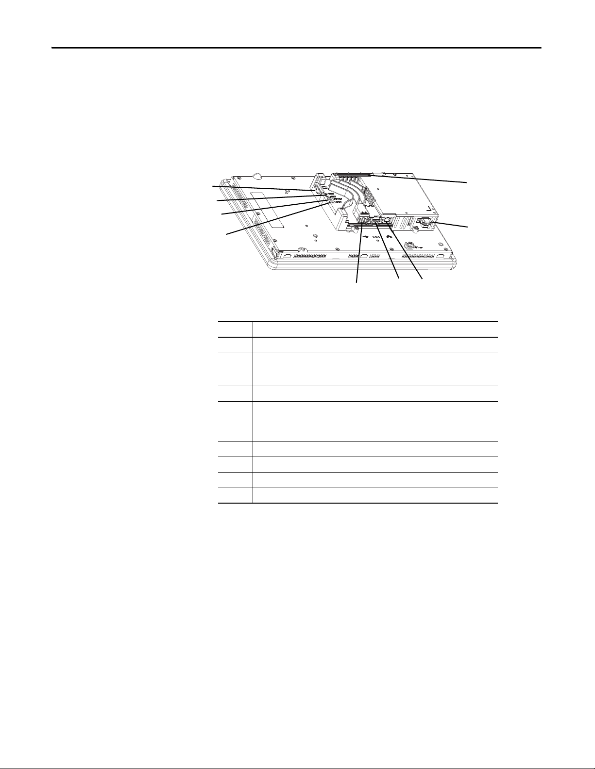
Configured Terminals
A configured terminal, ordered as a single-catalog number, has a display module
and logic module.
An optional DH+/DH-485, ControlNet, or Ethernet communication module
can be added later for additional network capabilities.
Table 8 - Logic Module Features
Item Feature
1 Network interface connector for optional communication module
2 AC or DC power input
• Isolated 18…32V DC
• 100…240V AC
3 Ethernet port for controller communication, 10/100 BaseT, Auto MDI/MDI-X
4 RS-232 serial port for file transfers, printing, and controller communication
5 Two USB 2.0 high-speed (type A) host ports for attaching USB devices including mouse,
keyboard, printer, and USB drives that are hot-swappable in nonhazardous locations
6 Reset switch to reset the terminal without having to power on and off
7 Default switch to access maintenance operations such as restoring factory defaults
8 Indicators provide communication and fault status
9 Secure Digital (SD) card slot supporting cat. no. 1784-SDx cards
(1) For DC applications using AC power, an external, remote AC-to-DC power supply, cat. no. 2711P-RSACDIN, is
available for DIN-rail mounting.
(1)
18 Rockwell Automation Publication 2711P-UM006E-EN-P - January 2017
Page 19
Overview Chapter 1
5
1
2
1
2
4
3
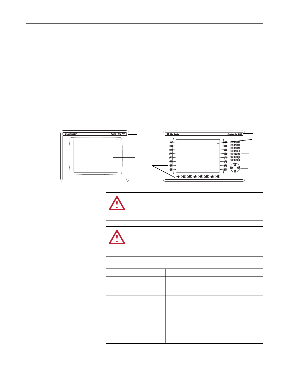
Operator Input
All 700 to 1500 display modules have TFT color, graphic displays with either
keypad, touch screen, or combination keypad/touch-screen input. Common
features and firmware provide for easy migration to a larger display:
• Eight-wire resistive touch screens are extremely accurate for operator
interfaces. When a point on the touch screen is pressed, the layers connect
and change the electrical current, which is then registered and processed.
• All keypad or combination keypad/touch-screen displays are similar except
for the number of functions keys.
To meet the requirements of specific environmental conditions, high-bright
displays, marine-certified displays, and conformal-coated displays are also
available. Plus, you can order field replaceable bezels.
ATT EN TI ON : Use a finger or gloved finger to operate the keypad. To operate the
touch screen, use a finger, gloved-finger or plastic stylus with a minimum tip
radius of 1.3 mm (0.051 in.). Using any other object or tool can damage the
keypad or touch screen.
ATT EN TI ON : Do not carry out multiple operations simultaneously. Doing so can
result in unintended operation:
• Touch only one operating element on the screen with one finger at one time.
• Press only one key on the terminal at one time.
Table 9 - Display Fe atures
Item Feature Description
1 Replaceable ID Label Product identification label can be replaced with custom label.
2 Display Analog resistive touch screen applies to touch-screen or combination
3 Numeric keypad 0…9, –, Backspace, Enter, Left and Right tab, Shift, Esc, Ctrl, Alt keys.
4 Navigation keys Use arrow keys for navigation. Use Alt+arrow to initiate these functions:
5 Fu nction keys
700 F1 …F10, K1…K12
1000 F1 …F16, K1…K16
1250 F1 …F20, K1…K20
1500 F1 …F20, K1…K20
Rockwell Automation Publication 2711P-UM006E-EN-P - January 2017 19
keypad/touch-screen terminals.
• Alt+left arrow (Home), Alt+right arrow (End)
• Alt+up arrow (Page Up), Alt+down arrow (Page Down)
Keys that can be configured in the application to perform operations. For
example, F1 can be configured to navigate to another screen.
Replaceable legends are available to customize the function key labels.
Page 20
Chapter 1 Overview
400/600 Terminal Selections
Bulletin Input Type Display Size Display Type Communication Power Operating System
|| || | | |
2711P- K = Keypad 4= 3.5 in. C = Color 5 = RS-232, USB A = AC 8 = Windows CE 6.0
B = Keypad and Touch 6 = 5.7 in. M = Grayscale 20 = Ethernet, RS-232, USB D = DC 9 = Windows CE 6.0 with extended features
T = Touch
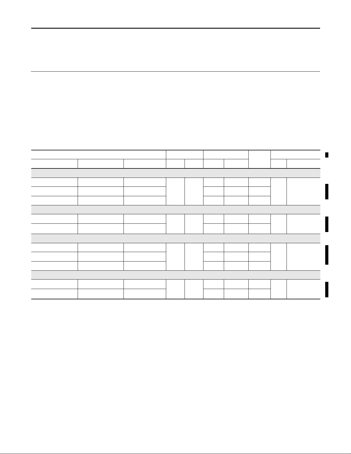
The table shows the catalog number breakdown for the 400 and 600 terminals.
Table 10 - PanelView Plus 6 - 400 Terminals without Extended Features
Cat. Nos. Display Communication Ports USB Ports
Keypad Keypad and Touch Size Type RS -232 Ethernet Host Device RAM Nonvolatile
2711P-K4M5A8 — 3.5-in. Grayscale • • • AC
2711P-K4M5D8 — • • • DC
2711P-K4M20A8 — • • • • AC
2711P-K4M20D8 — • • • • DC
2711P-K4C5A8 2711P-B4C5A8 3.5-in. Color • • • AC
2711P-K4C5D8 2711P-B4C5D8 • • • DC
2711P-K4C20A8 2711P-B4C20A8 • • • • AC
2711P-K4C20D8 2711P-B4C20D8 • • • • DC
(1) The terminal s support FactoryTalk View Machine Edition software, version 6.10 or later, and the Windows CE 6.0 operating system.
Input
Power
256
Memory (MB)
(approx. 73 MB
free user memory)
(1)
512
Table 11 - PanelView Plus 6 - 600 Terminals without Extended Features
Cat. Nos. Display Communication Ports USB Ports
Keypad Touch Keypad and Touch Size Type RS-232 Ethernet Host Device RAM Nonvolatile
2711P-K6M5A8 2711P-T6M5A8 2711P-B6M5A8 5.7-in. Grayscale • • • AC
2711P-K6M5D8 2711P-T6M5D8 2711P-B6M5D8 • • • DC
2711P-K6M20A8 2711P-T6M20A8 2711P-B6M20A8 • • • • AC
2711P-K6M20D8 2711P-T6M20D8 2711P-B6M20D8 • • • • DC
2711P-K6C5A8 2711P-T6C5A8 2711P-B6C5A8 5.7-in. Color • • • AC
2711P-K6C5D8 2711P-T6C5D8 2711P-B6C5D8 • • • DC
2711P-K6C20A8 2711P-T6C20A8 2711P-B6C20A8 • • • • AC
2711P-K6C20D8 2711P-T6C20D8 2711P-B6C20D8 • • • • DC
(1) The terminals support FactoryTalk View Machine Edition software, version 6.10 or later, and the Windows CE 6.0 operating system.
Input
Power
Memory (MB)
256
free user memory)
(approx. 73 MB
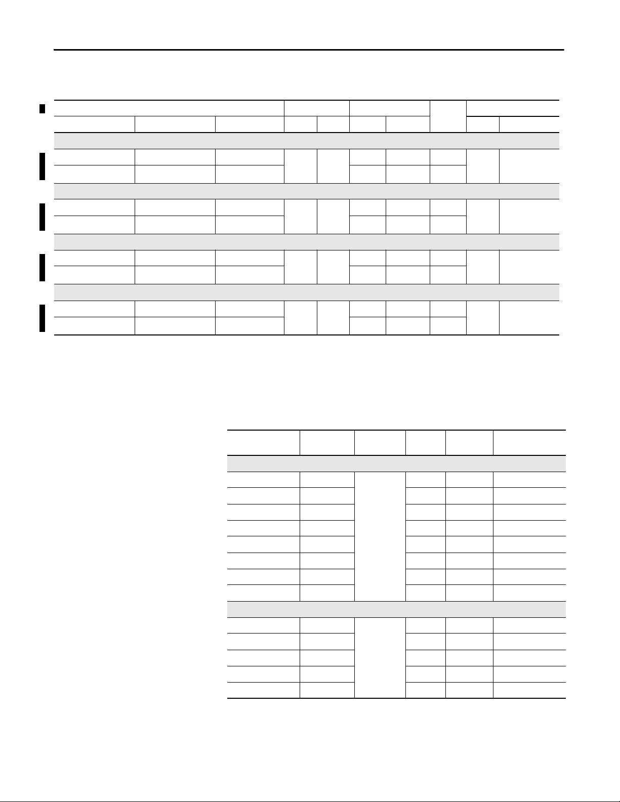
Table 12 - PanelView Plus 6 - 600 Terminals with Extended Features
Cat. Nos. Display Communication USB Ports
Keypad Touch Keypad and Touch Size Type RS-232 Ethernet Host Device RAM Nonvolatile
2711P-K6C5A9 2711P-T6C5A9 2711P-B6C5A9 5.7-in. Color • • • AC
2711P-K6C5D9 2711P-T6C5D9 2711P-B6C5D9 • • • DC
2711P-K6C20A9 2711P-T6C20A9 2711P-B6C20A9 • • • • AC
2711P-K6C20D9 2711P-T6C20D9 2711P-B6C20D9 • • • • DC
Input
Power
Memory (MB)
256
free user memory)
(approx. 73 MB
(1)
512
(1)
512
(1) The terminals support FactoryTalk View Machine Edition software, version 6.10 or later, and the Windows CE 6.0 operating system with extended features and file viewers.
20 Rockwell Automation Publication 2711P-UM006E-EN-P - January 2017
Page 21
Overview Chapter 1
700 to 1500 Terminal
The table shows the catalog number breakdown for the 700 to 1500 terminals.
Selections
Bulletin Input Type Display Size Display Type Communication
|| || | | | |
2711P- K = Keypad 7 = 6.5 in. C = Color 4 = Ethernet, RS-232 & (2) USB A = AC 8= Windows CE 6.0 K = Conf ormal-Coated
T = Touch 10 = 10.4 in. D = DC 9 = Windows CE 6.0 with
B = Keypad/Touch 12 = 12.1 in.
15 = 15 in.
(1) Optional communication mo dules are available as separate catalog numbers.
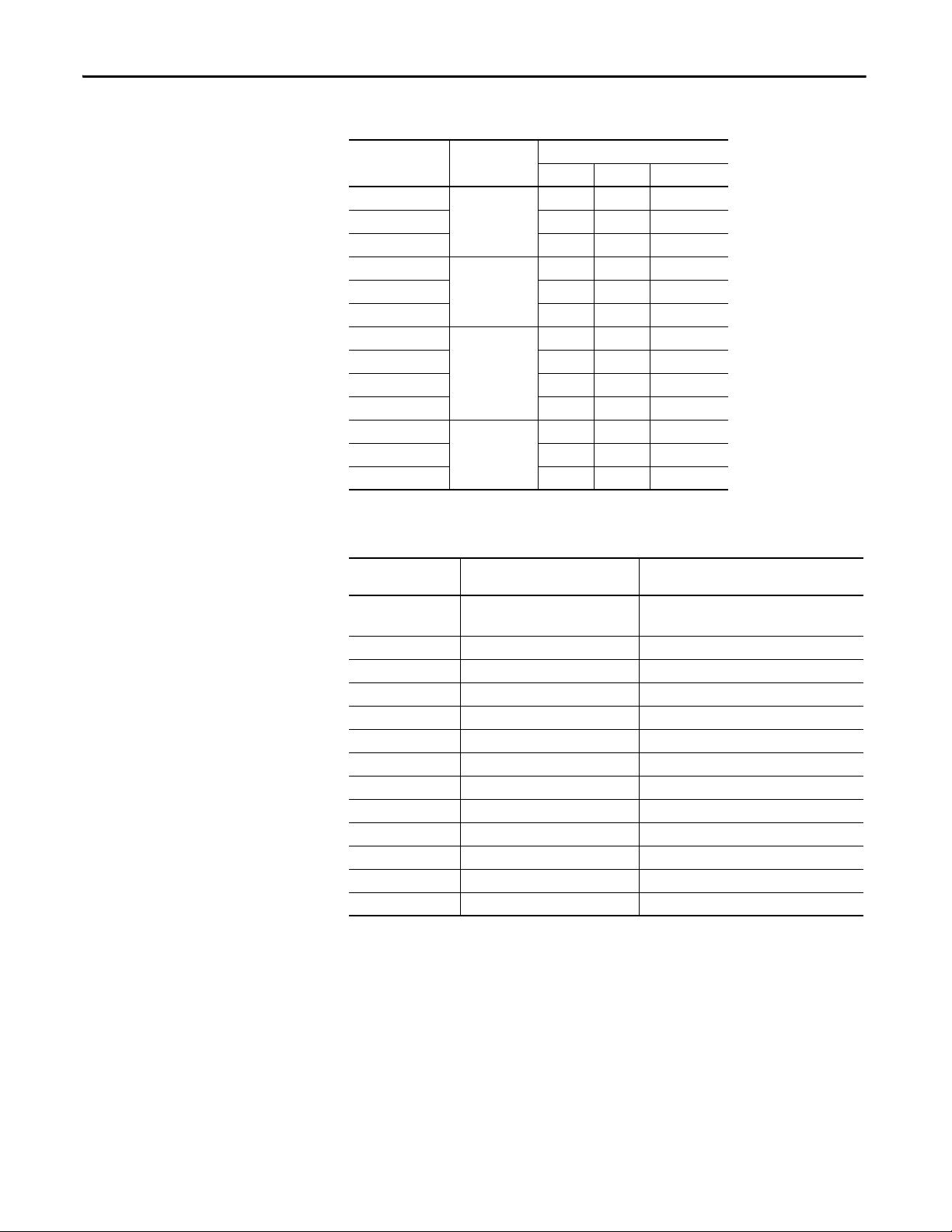
Table 13 - PanelView Plus 6 - 700 to 1500 Terminals without Extended Features
Cat. No. Display Communication
Keypad Touch Keypad/Touch Size Type RS-232 Ethernet RAM Nonvolatile
700 Model
2711P-K7C4D8 2711P-T7C4D8 2711P-B7C4D8 6.5-in. Color ••DC
– 2711P-T7C4D8K – ••DC
2711P-K7C4A8 2711P-T7C4A8 2711P-B7C4A8 ••AC
1000 Model
2711P-K10C4D8 2711P-T10C4D8 2711P-B10C4D8 10.4-in. Color ••DC
2711P-K10C4A8 2711P-T10C4A8 2711P-B10C4A8 ••AC
1250 Model
2711P-K12C4D8 2711P-T12C4D8 2711P-B12C4D8 12.1-in. Color ••DC
– 2711P-T12C4D8K – ••DC
2711P-K12C4A8 2711P-T12C4A8 2711P-B12C4A8 ••AC
1500 Model
2711P-K15C4D8 2711P-T15C4D8 2711P-B15C4D8 15-in. Color ••DC
2711P-K15C4A8 2711P-T15C4A8 2711P-B15C4A8 ••AC
(1)
Power Operating System Special Option
extended features
Input
Power
Memory (MB)
512
free user memory)
512
free user memory)
512
free user memory)
512
free user memory)
512
(approx. 79 MB
512
(approx. 79 MB
512
(approx. 79 MB
512
(approx. 79 MB
(1)
(1) The logic module supports FactoryTalk View Machine Edition software, version 6.0 or later, FactoryTalk ViewPoint software version 1.2 or later, and the Windows CE 6.0 operating system.
Rockwell Automation Publication 2711P-UM006E-EN-P - January 2017 21
Page 22
Chapter 1 Overview
Table 14 - PanelView Plus 6 - 700 to 1500 Terminals with Extended Features
Cat. No. Display Communication
Keypad Touch Keypad/Touch Size Type RS-232 Ethernet RAM Nonvolatile
700 Model
2711P-K7C4D9 2711P-T7C4D9 2711P-B7C4D9 6.5-in. Color ••DC
2711P-K7C4A9 2711P-T7C4A9 2711P-B7C4A9 ••AC
1000 Model
2711P-K10C4D9 2711P-T10C4D9 2711P-B10C4D9 10.4-in Color ••DC
2711P-K10C4A9 2711P-T10C4A9 2711P-B10C4A9 ••AC
1250 Model
2711P-K12C4D9 2711P-T12C4D9 2711P-B12C4D9 12.1-in Color ••DC
2711P-K12C4A9 2711P-T12C4A9 2711P-B12C4A9 ••AC
1500 Model
2711P-K15C4D9 2711P-T15C4D9 2711P-B15C4D9 15-in. Color ••DC
2711P-K15C4A9 2711P-T15C4A9 2711P-B15C4A9 ••AC
Input
Power
Memory (MB)
512
512
512
512
(approx. 79 MB
free user memory)
(approx. 79 MB
free user memory)
(approx. 79 MB
free user memory)
(approx. 79 MB
free user memory)
(1)
512
512
512
512
(1) The logic module supports FactoryTalk View Machine Edition software, version 6.0 or later, FactoryTalk ViewPoint software version 1.2 or later, and the Windows CE 6.0 operating system with extended
features and file viewers.
Accessories
Tables 15…28 list accessories for the PanelView Plus 6 terminals.
Table 15 - Display Modules - 700 to 1500 Terminals
Cat. No. Input Type Display Marine
Certified
700 Model
2711P-RDK7C Keypad 7-in. color
2711P-RDK7CK Keypad •
2711P-RDT7C Touch
2711P-RDT7CK Touch •
2711P-RDT7CM Touch •
2711P-RDB7C Keypad/Touch
2711P-RDB7CK Keypad/Touch •
2711P-RDB7CM Keypad/Touch •
1000 Model
2711P-RDK10C Keypad 10-4 in. color
2711P-RDT10C Touch
2711P-RDT10CM Touch •
2711P-RDB10C Keypad/Touch
2711P-RDB10CM Keypad/Touch •
Conformal
Coated
Built-in
Antiglare Overlay
22 Rockwell Automation Publication 2711P-UM006E-EN-P - January 2017
Page 23
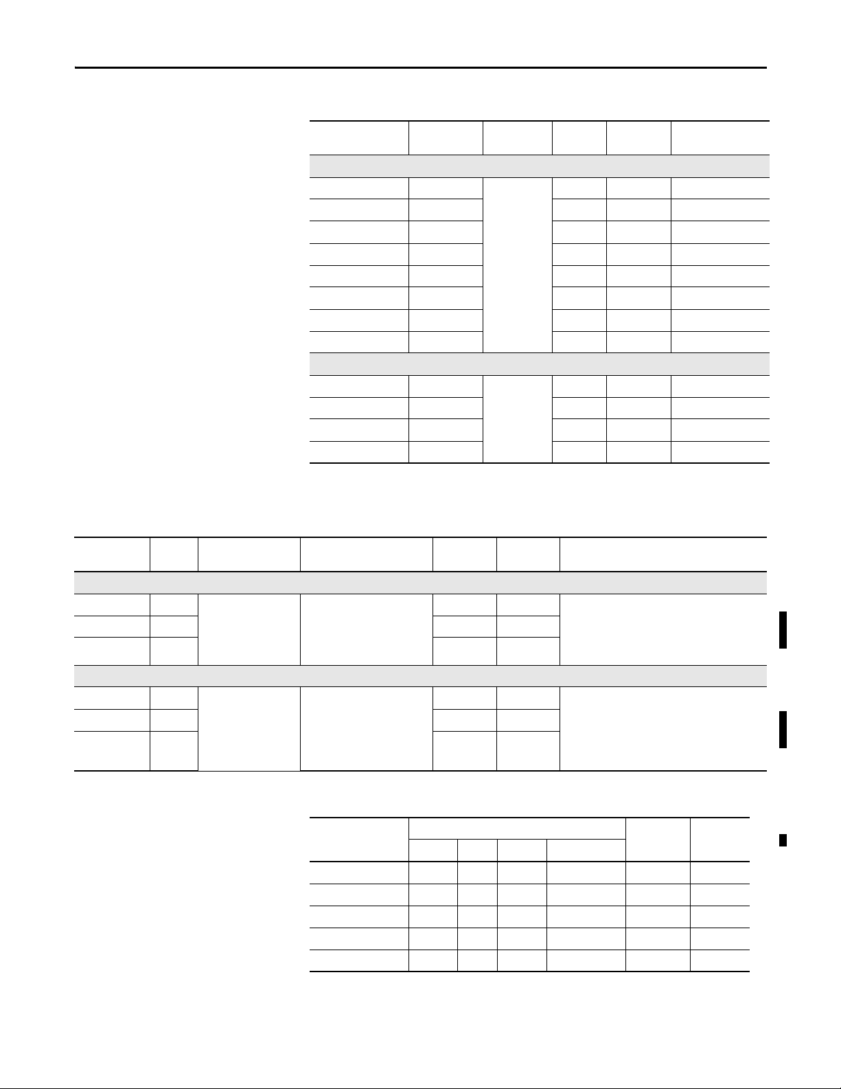
Table 15 - Display Modules - 700 to 1500 Terminals
Overview Chapter 1
Table 16 - Logic Modules - 700 to 1500 Terminals
Cat. No. Input Type Display Marine
Certified
Conformal
Coated
Built-in
Antiglare Overlay
1250 Model
2711P-RDK12C Keypad 12.1-in. color
2711P-RDK12CK Keypad •
2711P-RDT12C Touch
2711P-RDT12CK Touch •
2711P-RDT12H
(1)
Keypad/Touch
2711P-RDT12AG Touch •
2711P-RDB12C Keypad/Touch
2711P-RDB12CK Keypad/Touch •
1500 Model
2711P-RDK15C Keypad 15-in. color
2711P-RDT15C Touch
2711P-RDT15AG Touch •
2711P-RDB15C Keypad/Touch
(1) H at end of cat. no. refers to 1250 High-bright display module.
Cat. No.
Power
Input
Memory
RAM/Nonvolatile
Communication
Marine
Certified
Conformal
Coated
Without Standard Features
2711P-RP8A AC
2711P-RP8D DC •
2711P-RP8DK DC ••
512 MB/512 MB
(approximately 79 MB
free user memory)
• Ethernet
• RS-232
• Network interface for
communication module
••Windows CE 6.0 operating system
• FactoryTalk View Machine Edition runtime,
version 6.0 or later
• FactoryTalk ViewPoint software,
version 1.2 or later
With Extended Features
2711P-RP9A AC
2711P-RP9D DC •
2711P-RP9DK DC ••
512 MB/512 MB
(approximately 79 MB
free user memory)
• Ethernet
• RS-232
• Network interface
communication module
••Windows CE 6.0 operating system
with extended features and file viewers
• FactoryTalk View Machine Edition runtime,
version 6.0 or later
• FactoryTalk ViewPoint software,
version 1.2 or later
Table 17 - Communication Modules - 700 to 1500 Terminals
Cat. No.
Ethernet DH+ DH-485 ControlNet
2711P-RN6 ••
2711P-RN6K •• •
2711P-RN15S ••
2711P-RN15SK ••
2711P-RN20
(1)
•
Communication
Included Software
Conformal
(2)
Coated
Marine
Certified
(1) All terminals have an Ethernet port. The cat. no. 2711P-RN20 module provides an additional Ethernet port.
(2) Scheduled and unscheduled communication.
Rockwell Automation Publication 2711P-UM006E-EN-P - January 2017 23
Page 24
Chapter 1 Overview
Table 18 - Secure Digital (SD) Cards
Cat. No. Terminal Model Description
1784-SD1
1784-SD2 2 GB Secure Digital (SD) card
All terminals
2711C-RCSD USB to SD adapter for secure digit al card (SD)
1 GB Secure Digital (SD) card
700
(1)
Number of CCFL
Backlights
A and B 1
Table 19 - CCFL Backlight Replacements
Cat. No. Terminal Model Series
2711P-RL7C
2711P-RL7C2 C and D 1
2711P-RL10C
2711P-RL10C2 B and C 1
2711P-RL12C
2711P-RL12C2 C 1
1000
1250
A1
A and B 2
2711P-RL15C 1500 B 2
(1) These CCFL-backlight replacement catalog numbers do not apply to LED displays.
Table 20 - Antiglare Overlays
(1)
Cat. No.
Ter mina l Mo del
Keypad Touch Key/Touch
2711P-RGB4 400 grayscale or color • •
2711P-RGK6
600 grayscale or color
2711P-RGT6 •
2711P-RGK7
2711P-RGT7 •
2711P-RGK10
700 color
1000 color
2711P-RGT10 •
2711P-RGK12
2711P-RGT12 •
2711P-RGK15
2711P-RGT15 •
1250 color
1500 color
Operator Input
••
••
••
••
••
(1) Three overlays are shipped with each catalog number.
Table 21 - Solar Visor
Cat. No. Terminal Model Description
2711P-RVT12 1250 Solar visor for 1250 high-bright display module,
24 Rockwell Automation Publication 2711P-UM006E-EN-P - January 2017
cat. no. 2711P-RDT12H
Page 25
Overview Chapter 1
Table 22 - Function Key Legend Kits
Cat. No. Terminal Model
2711P-RFK6 600 keypad
2711P-RFK7 700 keypad
2711P-RFK10 1000 keypad
2711P-RFK12 1250 keypad
2711P-RFK15 1500 keypad
(1) Applies to keyp ad and keypad/touch-screen termin als.
(1)
Description
Blank legend inserts and software
Table 23 - Mounting Hardware
Cat. No. Terminal Model Description Quantity
2711P-RTFC 400 or 600 Replacement mounting levers 8
2711P-RTMC 700 to 1500 Replacement Mounting clips 8
Table 24 - Replacement Battery
Cat. No. Terminal Model Description
2711P-RY2032 All terminals Replacement CR2032 coin-cell equivalent battery
Table 25 - Cables
Cat. No. Terminal Model Description Length
2711C-CBL-UU02
(1)
700 to 1500 Programming cable that connects the USB device port of
2 m (6.5 ft)
the terminal to a USB host port of a computer
6189V-USBCBL2 400 and 600 Programming cable that connects the USB device port of
1.8 m (6 ft)
the terminal to a USB host port of a computer
(1) Only for Series A terminals with a mini-USB port, type B.
Table 26 - Power Supply and Power Terminal Blocks
Cat. No. Terminal Model Description Quantity
2711P-RSACDIN All terminals DIN-rail power supply, AC-to-DC, 100…240V AC, 50…60 Hz 1
2711P-RVAC 400 and 600 AC power terminal block 10
2711P-6RSA AC module converts a DC-powered terminal to AC power 1
2711-TBDC DC power terminal block 10
2711P-RTBAC3 700 to 1500 AC power terminal block 10
2711P-RTBDC2 DC power terminal block 10
Rockwell Automation Publication 2711P-UM006E-EN-P - January 2017 25
Page 26
Chapter 1 Overview
Table 27 - Bezel Replacements
Cat. No. Terminal Model
Keypad Touch Key/Touch
2711P-RBK7
2711P-RBT7 •
700
Operator Input
•
2711P-RBB7 •
2711P-RBK10
2711P-RBT10 •
1000
•
2711P-RBB10 •
2711P-RBK12
2711P-RBT12 •
2711P-RBT12H
(1)
1250
•
•
2711P-RBB12 •
2711P-RBK15
2711P-RBT15 •
1500
•
2711P-RBB15 •
(1) Applies to the cat. no. 2711P-RDT12H 1250 high-bright display module.
Table 28 - Adapter Plates
Cat. No.
2711P-RAK4 400 keypad or keypad/touch
600 touch
2711P-RAK6 600 keypad or keypad/touch PanelView Standard 600 keypad
2711P-RAK7 700 keypad or keypad/touch PanelView Standard 900 keypad
2711P-RAT7 700 touch PanelView Standard 900 touch
2711P-RAK10 1000 keypad or keypad/touch PanelView 1000/1000e keypad
2711P-RAT10 1000 touch PanelView 1000/1000e touch
2711P-RAK15 1500 keypad or keypad/touch PanelView 1200e/1400e keypad
2711P-RAT15 1500 touch PanelView 1200e/1400e touch
2711P-RAK12E 1250 keypad
2711P-RAT12E2 1250 touch
2711P-RAT12E 1250 touch
2711P-RAK12S 1250 keypad
2711P-RAT12S 1250 touch
Adapts This
PanelView Plus 6 Termin al
To Thi s Term ina l Cut out
PanelView Standard 550 keypad
(1)
(2)
(2)
(1)
or keypad/touch PanelView Standard 1400 keypad
(2)
PanelView 1200/1400e keypad
PanelView 1200 touch
PanelView 1200e/1400e touch
PanelView Standard 1400 touch
(1) Applies also to PanelView 1000/1000e keypad or keypad/touch terminals.
(2) Applies also to PanelView 1000/1000e touch terminals.
26 Rockwell Automation Publication 2711P-UM006E-EN-P - January 2017
Page 27
Install Terminal
Top ic Pa ge
Required Circuit Parameters for USB Peripheral Devices 29
Mounting Clearances 30
Panel Guidelines 30
Panel Cutout Dimensions 30
Remove and Install the Power Terminal Block 37
Mount the 400/600 Terminal in a Panel 33
Mount the 700 to 1500 Terminal in a Panel 35
Remove and Install the Power Terminal Block 37
DC Power Connections 38
AC Power Conn ection s 41
Initial Startup 43
Reset the Terminal 43
Chapter 2
ATTENTION: Environment and Enclosure
This equipment is intended for use in a Pollution Degree 2 industrial environment, in overvoltage Category II applications (as defined
in IEC 60664-1), at altitudes up to 2000 m (6561 ft) without derating.
The terminals are intended for use with programmable logic controllers. Terminals that are AC powered must be connected to the
secondary of an isolating transformer.
This equipment is considered Group 1, Class A industrial equipment according to IEC CISPR 11. Without appropriate precautions, there
may be difficulties with electromagnetic compatibility in residential and other environments due to conducted or radiated
disturbances.
Korean Radio Wave Suitability Registration - When so marked this equipment is registered for Electromagnetic Conformity
Registration as business equipment (A), not home equipment. Sellers or users are required to take caution in this regard.
This equipment is supplied as open-type equipment. It must be mounted within an enclosure that is suitably designed for those
specific environmental conditions that will be present and appropriately designed to prevent personal injury resulting from
accessibility to live parts. The interior of the enclosure must be accessible only by the use of a tool. The terminals meet specified
NEMA, UL type, and IEC ratings only when mounted in a panel or enclosure with the equivalent rating. Subsequent sections of this
publication may contain additional information regarding specific enclosure type ratings that are required to comply with certain
product safety certifications.
In addition to this publication, see the following:
• Industrial Automation Wiring and Grounding Guidelines, publication 1770-4.1
, for additional installation requirements
• NEMA Standards 250 and IEC 60529, as applicable, for explanations of the degrees of protection provided by different
types of enclosure
Rockwell Automation Publication 2711P-UM006E-EN-P - January 2017 27
Page 28
Chapter 2 Install Terminal
North American Hazardous Location Approval
The following information applies when operating this equipment in
hazardous locations.
When marked, these products are suitable for use in "Class I,
Division 2, Groups A, B, C, D"; Class I, Zone 2, Group IIC, Class II,
Division II, Groups F, G; Class III hazardous locations and
nonhazardous locations only. Each product is supplied with
markings on the rating nameplate indicating the hazardous
location temperature code. When combining products within a
system, the most adverse temperature code (lowest "T" number)
may be used to help determine the overall temperature code of the
system. Combinations of equipment in your system are subject to
investigation by the local Authority Having Jurisdiction at the time
of installation.
WARNING: EXPLOSION HAZARD
• Do not disconnect equipment unless power has been removed
or the area is known to be nonhazardous.
• Do not disconnect connections to this equipment unless
power has been removed or the area is known to be
nonhazardous.
• Substitution of components may impair suitability for Class I,
Division 2.
• Peripheral equipment must be suitable for the location in
which it is used.
• The battery or real-time clock module in this product must
only be changed in an area known to be nonhazardous.
• All wiring must be in accordance with Class I, Division 2, Class
II, Division 2, or Class III, Division 2 wiring methods of Articles
501, 502 or 503, as appropriate, of the National Electrical Code
and/or in accordance with Section 18-1J2 of the Canadian
Electrical Code, and in accordance with the authority having
jurisdiction.
Informations sur l’utilisation de cet équipement en environnements
dangereux.
Lorqu'ils sont marqués, ces produits ne conviennent qu'à une
utilisation en environnements Classe I, Division 2, Groupes A, B, C
et D ; Cla sse I, Zone 2, Groupe IIC, Classe II, Divisio n II, Gro upes F et
G ; Classe III, dangereux ou non dangereux. Chaque produit est
livré avec des marquages sur sa plaque d'identification qui
indiquent le code de température pour les environnements
dangereux. Lorsque plusieurs produits sont combinés dans un
système, le code de température le plus défavorable (code " T " le
plus faible) peut être utilisé pour déterminer le code de
température global du système. Les combinaisons d'équipements
dans le système sont sujettes à inspection par les autorités locales
qualifiées au moment de l'installation.
AVERTISSEMENT : RISQUE D’EXPLOSION
• Couper le courant ou s'assurer que l'environnement est
classé non dangereux avant de débrancher l'équipement.
• Couper le courant ou s'assurer que l'environnement est
classé non dangereux avant de débrancher les connecteurs.
• La substitution de composants peut rendre cet équipement
inadapté à une utilisation en environnement de Classe I,
Division 2
• Les équipements périphériques doivent s'adapter à
l'environnement dans lequel ils sont utilisés.
• La batterie ou le module de l'horloge en temps réel de ce
produit doit être changé(e) uniquement dans un
environnement classé sans risque.
• Tous les systèmes de câblage doivent être de Classe I,
Division 2, Classe II, Division 2, ou Classe III, Division 2,
conformément aux méthodes de câblage indiquées dans
les Articles 501, 502 ou 503 du National Electrical Code
(Code Electrique National) et/ou conformément à la Section
18-1J2 du Canadian Electrical Code (Code Electrique
Canadien), et en fonction de l'autorité de jurisdiction.
Table 29 - Temperature Codes - PanelView Plus 6 Terminals
Terminal Model Input Power Temperature Code Description
400 and 600 terminals DC T4 Do not install terminals rated T4 in environments where atmospheric gases have ignition
AC T4
700 to 1500 terminals DC T4
AC T3 Do not install terminals rated T3 in environments where atmospheric gases have ignition
28 Rockwell Automation Publication 2711P-UM006E-EN-P - January 2017
temperatures less than 135 °C (275 °F).
temperatures less than 200 °C (392 °F).
Page 29

Install Terminal Chapter 2
Nonincendive
Field-Wiring Apparatus
Associated Nonincendive Field-wiring Apparatus
PanelView Plus 6 Host Product
USB Peripheral Device
USB Peripheral Device
USB Host Port
USB Host Port
Required Circuit Parameters for USB Peripheral Devices
The terminals contain one or two USB host ports that comply with hazardous location environments. Field-wiring
compliance requirements are provided in compliance with the National Electrical Code, Article 500.
Figure 4 - PanelView Plus 6 Terminals Control Drawing
PanelView Plus 6 terminals provide one or two separately-powered USB host ports. Ta b l e 3 0 defines the circuit parameters
of the USB host ports.
Table 30 - Circuit Parameters for USB Host Ports
Parameter Value Parameter Definition
V
I
sc (USB)
C
a (USB)
L
a (USB)
oc (USB)
5.25V DC Open circuit voltage of the host USB port.
The maximum applied voltage rating, V
or equal to V
1.68 A Maximum output current of the host USB port.
The maximum current, I
greater than or equal to I
10 μF This value is the maximum total capacitance that can be connected to the USB host port. The total
capacitance of the USB peripheral device and its associated cable must not exceed the indicated value.
The maximum total capacitance, C
must be less that or equal to C
15 μH This value is the maximum total inductance that can be connected to the USB host port. The total
inductance of the USB peripheral device and its associated cable must not exceed the indicated value.
The maximum total inductance, L
must be less than or equal to L
oc (USB)
.
max (peripheral)
sc (USB).
max (peripheral)
, to which each USB peripheral device can be subjected must be
i (peripheral)
.
a (USB)
i (peripheral)
.
a (USB)
, of the USB peripheral device must be greater than
, and cable capacitance of the separate USB peripheral device
, and cable inductance of the separate USB peripheral device
V
max (peripheral)
as appropriate
I
max (peripheral)
C
i (peripheral)
L
i (peripheral)
+ C
+ L
≥ V
oc (USB)
≥ I
sc (USB)
cable(USB)
cable
≤ L
,
≤ C
a (USB)
a (USB)
Application Information
Per the National Electrical Code, the circuit parameters of associated field-wiring apparatus for use in hazardous locations
must be coordinated with the host product such that their combination remains nonincendive. PanelView Plus 6 terminals
and the USB peripheral devices must be treated in this manner.
The USB peripheral devices and their associated cabling must have circuit parameters with the limits given in Ta b l e 3 0
them to remain nonincendive when used with the PanelView Plus 6 USB host port.
If cable capacitance and inductance are not known, use the following values from ANSI/ISA-RP 12.06.01-2003:
C
= 197 pF/m (60 pF/ft)
cable
L
= 0.7 μH/m (0.20 μH/ft)
cable
Nonincendive field-wiring must be wired and separated in accordance with 501.10(B)(3) of the National Electrical Code
(NEC) ANSI/NFPA 70 or other local codes as applicable. This associated nonincendive field-wiring apparatus has not
been evaluated for use in combination with another associated nonincendive field-wiring apparatus.
Rockwell Automation Publication 2711P-UM006E-EN-P - January 2017 29
for
Page 30

Chapter 2 Install Terminal
Mounting Clearances
Panel Guidelines
Plan for adequate space around the terminal, inside the enclosure, for ventilation
and connections. Consider heat produced by other devices in the enclosure. The
ambient temperature around the terminal must be 0…55 °C (32…131 °F).
Table 31 - Minimum Required Clearances
Product Area Minimum Clearance
Top 51 mm (2 in.)
Bottom 102 mm (4 in.)
Side 25 mm (1 in.)
Back 0 mm (0 in.)
A clearance of 102 mm (4 in.) is sufficient on the side of the terminal to insert
and remove an SD card, and on the bottom of terminal for connections.
The terminals are panel-mounted devices intended to mount in the door or wall
of a NEMA rated, UL Type rated, or IP rated enclosure:
• Supporting panels must have a mounting thickness of 1.5…4.8 mm
(0.060…0.188 in.).
• The material strength and stiffness of the panel must be sufficient to hold
the terminal and maintain an appropriate seal against water and dust.
• The panel surface must be flat and free of imperfections to maintain an
adequate seal and NEMA and UL Type ratings.
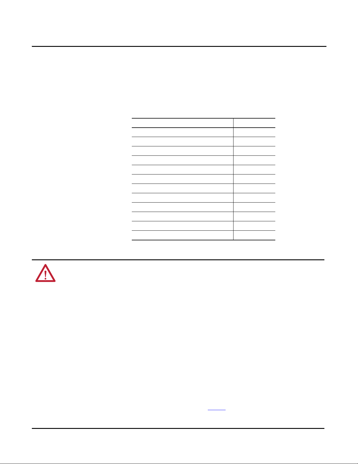
Panel Cutout Dimensions
Use the full size template shipped with your terminal to mark the panel cutout
dimensions.
Table 32 - Panel Cutout Dimensions
Terminal Input Type Height, mm (in.) Width, mm (in.)
400 Keypad or keypad/touch 123 (4.86) 156 (6.15)
600
700
1000
1250
1500
(1) Also applies to high-bright display module, cat. no. 2711P-RDT12H.
Keypad or keypad/touch 142 (5.61) 241 (9.50)
Touch 123 (4.86) 156 (6.15)
Keypad or keypad/touch 167 (6.57) 264 (10.39)
Touch 154 (6.08) 220 (8.67)
Keypad or keypad/touch 224 (8.8) 375 (14.75)
Touch 224 (8.8) 305 (12.00)
Keypad or keypad/touch 257 (10.11) 390 (15.35)
(1)
Tou c h
Keypad or keypad/touch 305 (12.00) 419 (16.50)
Touch 305 (12.00) 391 (15.40)
257 (10.11) 338 (13.29)
30 Rockwell Automation Publication 2711P-UM006E-EN-P - January 2017
Page 31

Install Terminal Chapter 2
a
b
c
d
a
b
d
c
1
6
1
6
6
1
a
b
c
d
Product Dimensions
Ta b l e 3 3 and Ta b l e 3 4 provide product dimensions for all PanelView Plus 6
terminals.
Figure 5 - PanelView Plus 6 - 400 Keypad or Keypad/Touch
Figure 6 - PanelView Plus 6 - 600 Touch
Figure 7 - PanelView Plus 6 - 600 Keypad or Keypad/Touch
F1
F6
F4F3 F5
F2
F9F8 F10
F7
Table 33 - PanelView Plus 6 - 400 and 600 Product Dimensions
Terminal Input Type
Height (a)
mm (in.)
Width (b)
mm (in.)
400 Keypad or keypad/touch 152 (6.0) 185 (7.28) 60 (2.35) 90 (3.54)
Keypad or keypad/touch 167 (6.58) 266 (10.47) 68 (2.68) 98 (3.86)
600
Touch 152 (6.0) 185 (7.28) 68 (2.68) 98 (3.86)
Depth (c)
mm (in.)
Depth (d) with AC module
mm (in.)
Rockwell Automation Publication 2711P-UM006E-EN-P - January 2017 31
Page 32

Chapter 2 Install Terminal
d
c
d
c
a
a
b
b
The 700 to 1500 terminals look similar. The 1000 keypad and keypad/touch
terminals are shown for illustrative purposes.
Figure 8 - PanelView Plus 6 - 1000 Keypad, Keypad/Touch, Touch
Table 34 - PanelView Plus 6 - 700 to 1500 Terminal Dimensions
Terminal Input Type
700 Keypad or keypad/touch 193 (7.58) 290 (11.40) 55 (2.18) 83 (3.27)
Touch 179 (7.04) 246 (9.68) 55 (2.18) 83 (3.27)
1000 Keypad or keypad/touch 248 (9.77) 399 (15.72) 55 (2.18) 83 (3.27)
Touch 248 (9.77) 329 (12.97) 55 (2.18) 83 (3.27)
1250 Keypad or keypad/touch 282 (11.12) 416 (16.36) 55 (2.18) 83 (3.27)
Touch 282 (11.12) 363 (14.30) 55 (2.18) 83 (3.27)
Tou c h
(high-bright module)
1500 Keypad or keypad/touch 330 (12.97) 469 (18.46) 65 (2.55) 93 (3.65)
Touch 330 (12.97) 416 (16.37) 65 (2.55) 93 (3.65)
Height (a)
mm (in.)
282 (11.12) 363 (14.30) 74 (2.9) 101 (3.99)
Width (b)
mm (in.)
Depth (c)
Display to Logic Module
mm (in.)
Depth (d)
Display to Comm Module
mm (in.)
32 Rockwell Automation Publication 2711P-UM006E-EN-P - January 2017
Page 33

Install Terminal Chapter 2
6
1
1
2
3
4
5
6
Notch
Alignment Marks
Orientation of Slot Varies
Gasket
FAULT
COMM
FAULT
Mount the 400/600 Terminal in a Panel
The terminals were designed for single-person installation. No tools are required
except for those needed to make the panel cutout
Mounting levers secure the terminal to the panel. Four or six levers are required
depending on the terminal model. The levers insert into the mounting slots on
the top and bottom of the terminal.
Each mounting slot has six notches with alignment marks that are locking
positions for a lever. The thickness of the panel in which you mount the terminal
determines the locking position required to maintain the NEMA/UL Type seal.
Table 35 - Lever Locking Positions
Mounting Slot
Lever Lock
Position
1
2
3
4
5
6
Panel T hickness R ange
1.50…2.01 mm (0.060…0.079 in.) 16
2.03…2.64 mm (0.080…0.104 in.) 14
2.67…3.15 mm (0.105…0.124 in.) 12
3.17…3.66 mm (0.125…0.144 in.) 10
3.68…4.16 mm (0.145…0.164 in.) 8/9
4.19…4.80 mm (0.165…0.188 in.) 7
Typic al
Gauge
Follows these steps to mount the terminal in a panel.
ATT EN TI ON :
Disconnect all electrical power from the panel before making the panel cutout.
Make sure the area around the panel cutout is clear and that the panel is clean of
any debris, oil, or other chemicals.
Make sure metal cuttings do not enter any components already installed in the
panel and that the edges of the cutout have no burrs or sharp edges.
Failure to follow these warnings can result in personal injury or damage to panel
components.
1. Cut an opening in the panel by using the cutout template shipped with the
terminal or the cutout dimensions on page 30
.
2. Verify the sealing gasket is present on the terminal.
This gasket forms a compression type seal. Do not use sealing compounds.
Rockwell Automation Publication 2711P-UM006E-EN-P - January 2017 33
Page 34

Chapter 2 Install Terminal
F1
F2
F4F3 F5
F6
F7
F9F8 F10
Flat Side of Lever
Mounting Slots
Mounting Levers
TIP
FAULT
COMM
FAULT
DEFAULT
RESET
Notch
Rotate lever until notch in lever aligns with
proper alignment mark on terminal.
Alignment Marks
6
1
1
3
4
2
1
35
4
62
3. Place the terminal in the panel cutout.
4. Insert all mounting levers into the mounting slots on the terminal.
Slide each lever until the flat side of the lever touches the panel surface.
5. When all levers are in place, slide each lever an additional notch or two
until you hear a click.
Refer to Table 35 on page 33
as a guide to determine the locking positions
for your panel thickness.
6. Rotate each lever in direction indicated until it is in the final position.
Levers rotate in same direction on top and bottom of terminal.
Follow the appropriate locking sequence for the optimal terminal fit.
FAULT
FAULT
COMM
DEFAULT
RESET
7. Inspect all levers to verify they are in the correct and same locked position.
ATTENTION: All levers must be locked to provide an adequate gasket
seal between the terminal and the panel. Rockwell Automation
assumes no responsibility for water or chemical damage to the terminal
or other equipment within the enclosure because of improper
34 Rockwell Automation Publication 2711P-UM006E-EN-P - January 2017
installation.
Page 35

Install Terminal Chapter 2
IMPORTANT
Sealing Gasket
Mount the 700 to 1500 Terminal in a Panel
Mounting clips secure the 700 to 1500 terminals in a panel. The number of clips
varies by terminal size. Tools required for installation include panel cutout tools,
a small, slotted screwdriver, and a torque wrench for tightening the
mounting clips.
ATT EN TI ON :
Disconnect all electrical power from the panel before making the panel cutout.
Make sure the area around the panel cutout is clear and that the panel is clean of
any debris, oil, or other chemicals.
Make sure metal cuttings do not enter any components already installed in the
panel and that the edges of the cutout have no burrs or sharp edges.
Failure to follow these warnings can result in personal injury or damage to panel
components.
For outdoor installations using a high-bright display module, catalog number
2711P-RDT12H, refer to Appendix B on page 179
considerations.
Follow these steps to mount the terminal in a panel.
for important installation
1. Cut an opening in the panel by using the panel cutout template shipped
with the terminal or the cutout dimensions on page 30
2. Verify the terminal sealing gasket is properly positioned on the terminal.
This gasket forms a compression type seal. Do not use sealing compounds.
Be careful not to pinch the legend strip during installation.
.
Rockwell Automation Publication 2711P-UM006E-EN-P - January 2017 35
Page 36

Chapter 2 Install Terminal
Mounting Clip Slot
Mounting Clip
1
2
3
4
5
6
7
8
Tor que Se que nce
6 Clips
246
513
Tor que S eq uen ce
4 Clips
14
3
2
Tor que Se que nce
8 Clips
3. Place the terminal in the panel cutout.
4. Slide the ends of the mounting clips into the slots on the terminal.
5. Tighten the mounting clip screws by hand until the gasket seal contacts the
mounting surface uniformly.
6. Tighten the mounting clips screws to a torque of 0.90…1.1 N•m
(8…10 lb•in) by using the specified sequence, making sure not to
overtighten.
ATT EN TI ON : Tighten the mounting clips to the specified torque to provide a
proper seal and to prevent damage to the product. Allen-Bradley assumes no
responsibility for water or chemical damage to the product or other equipment
within the enclosure because of improper installation.
36 Rockwell Automation Publication 2711P-UM006E-EN-P - January 2017
Page 37

Install Terminal Chapter 2
Remove and Install the Power Terminal Block
The terminals are shipped with a power terminal block installed. You can remove
the terminal block for ease of installation, wiring, and maintenance.
WARNING: Explosion Hazard
If you connect or disconnect wiring while the power is on, an electrical arc can
occur. This could cause an explosion in hazardous location installations. Be sure
that power is removed and the area is nonhazardous before proceeding.
Failure to remove power can result in electrical shock or damage to the terminal.
The terminal blocks have different colors and markings for AC and DC power
connections. Always match the terminal block color to its mating connector. The
power terminal blocks are not intended for daisy chaining power.
Use a 0.6 x 3.5 mm flat blade screwdriver for terminal block wiring.
Table 36 - Wire Specifications for Power Input Terminal Block
Terminal Wire Type Dual-wire Size
400, 600
700 to 1500
(1) Two-wire max per terminal.
Stranded or solid
Cu 90 °C (194 °F)
0.3…1.3 mm
22…16 AWG
(1)
Single-wire Size Strip Length Screw Torque
2
0.3…2.1 mm
(22…14 AWG)
2
7 mm (0.28 in.)
0.45…0.56 N•m
(4…5 lb•in)
0.56 …0.90 N•m
(5…8 lb•in)
400 and 600 Terminals
Follow these steps to remove the terminal block from a 400 or 600 terminal.
1. Insert the tip of a small, flat-blade screwdriver into the terminal block
access slot.
2. Gently pry the terminal block to rotate it away from the terminal; this
releases the locking mechanism.
Follow these steps to replace the terminal block.
1. Press terminal block base in first with block leaning outward.
2. Gently push the top of the terminal block to rotate it into place; it snaps
when seated.
Rockwell Automation Publication 2711P-UM006E-EN-P - January 2017 37
Page 38

Chapter 2 Install Terminal
Three-position
AC Terminal Block
Two -p os it io n
DC Terminal Block
TIP
700 to 1500 Terminals
Follow these steps to remove the terminal block from a 700 to 1500 terminal.
1. Loosen the two screws that secure the terminal block.
2. Gently pull the terminal block away from the connector.
Follow these steps to install the terminal block.
1. Reattach the terminal block to the connector until seated.
2. Tighten the two screws that secure the terminal block to a torque of
0.40…0.51 N•m (3.5…4.5 lb•in).
DC Power Connections
Terminals with an integrated 24V DC power supply have these power ratings.
Table 37 - DC Power Ratings
Terminal Power Supply Input Voltage Power Consumption
400, 600 Nonisolated 24V DC nom (18…30V DC) 15 W max (0.6 A at 24V DC)
700 to 1500 Isolated 24V DC nom (18…32V DC) 70 W max (2.9 A at 24V DC)
The power supply is internally protected against reverse polarity. Connecting
DC+ or DC- to the earth/ground terminal can damage the device.
ATT EN TI ON : Applying an AC power source to a terminal with a DC power input
can damage the device.
External Power Supply
Use a dedicated 24V DC, safety extra-low voltage (SELV) or protective
extra-low voltage (PELV) power supply to power each PanelView Plus 6 device.
ATT EN TI ON : Use a SELV or PELV power supply as required by local wiring codes
for your installation. These power supplies provide protection so that under
normal and single fault conditions, the voltage between conductors and earth
ground does not exceed a safe value.
38 Rockwell Automation Publication 2711P-UM006E-EN-P - January 2017
Terminals with an isolated DC power supply can be powered by the same
power source as other equipment, such as a DC power bus.
Page 39

Install Terminal Chapter 2
IMPORTANT
IMPORTANT
PanelView Plus 6 devices were tested to operate with the catalog number
2711P-RSACDIN power supply. To use another power supply, review the
criteria in the table.
Table 38 - Power Supply Criteria
If the PanelView Plus 6 Device Use a Description
Connects to equipment with isolated
communication ports
Does not connect to other equipment
Connects to equipment with nonisolated communication ports
SELV or PELV power supply Other equipment can share this power
Dedicated, isolated, and
ungrounded SELV source to
power each terminal
supply with the PanelView Plus 6 device
provided that no ground loops are created.
A PELV source internally connec ts the
negative power terminal to chassis ground.
This prevents ground loops from damaging
the device.
All of the communication ports on the terminals and supported
communication modules are isolated, with the exception of the USB ports.
Earth/Ground Connection
PanelView Plus 6 devices with a DC power input have an earth/ground terminal
that you must connect to a low-impedance earth/ground.
• On 400 and 600 terminals, the earth/ground connection is on the power
terminal block.
• On 700 to 1500 terminals, the earth/ground connection is on the rear of
the display module.
The earth/ground connection to ground is mandatory. This connection is
required for the following:
• Noise immunity, reliability, and Electromagnetic Compliance (EMC) with
the European Union (EU) EMC directive for CE-mark conformance
• Safety by Underwriters Laboratory
Table 39 - Earth Wire Specifications for DC Power
Terminal Symbol Wire Type Wire Gauge Terminal Screw Torque
400, 600 GND
700 to 1500 GND
Stranded or solid
Cu 90 °C (194 °F)
Stranded or solid
Cu 90 °C (194 °F)
2.1…3.3 mm
(14…12 AWG)
2.1…5.3 mm
(14…10 AWG)
2
2
0.45…0.56 N•m
(4…5 lb•in)
1.13…1.36 N•m
(10…12 lb•in)
ATT EN TI ON : Damage or malfunction can occur when a voltage potential exists
between two separate ground points. Make sure the terminal does not serve as
a conductive path between ground points at different potentials.
Rockwell Automation Publication 2711P-UM006E-EN-P - January 2017 39
Page 40

Chapter 2 Install Terminal
7 mm
20 mm
+
–
Earth/Ground to Ground Bus
DC -
DC+
GND
DC+
DC –
Functional Earth to Ground Bus
400 or 600 Terminal 700 to 1500 Terminal
Connect DC Power
WARNING: Explosion Hazard
Do not disconnect equipment unless power has been switched off and area is
known to be nonhazardous.
Disconnect all power before installing or replacing components. Failure to
disconnect power can result in electrical shock or damage to the terminal.
Follow these steps to connect the terminal to DC power.
1. Verify that the terminal is not connected to a power source.
2. Strip 7 mm (0.28 in.) of insulation from the ends of the wires.
3. Secure the DC power wires to the marked terminals (+ and –) on the
power terminal block.
4. Secure the earth/ground wire.
• On 400 and 600 terminals, secure the earth/ground wire to the
functional earth/ground terminal on the power terminal block.
• On 700 to 1500 terminals, secure the earth/ground wire to the
functional earth screw on the back of the display.
5. Apply power to the terminal.
40 Rockwell Automation Publication 2711P-UM006E-EN-P - January 2017
Page 41

Install Terminal Chapter 2
IMPORTANT
AC Power Connections
Terminals with an integrated AC power supply have these power ratings.
Table 40 - AC Power Ratings
Terminal Input Voltage Power Consumption
400, 600 100…240V AC (50…60 Hz) 35VA max
700, 1000, 1250, 1500 100…240V AC (50…60 Hz) 160VA max
Protective Earth and Functional Earth Connections
PanelView Plus 6 devices with an AC power input have a protective earth
terminal you must connect to a low-impedance earth ground. The protective
earth terminal is on the power input terminal block.
In addition to the protective earth connection, the 700 and 1500 terminals also
have a functional earth terminal that you must connect to a low-impedance
earth ground. The functional earth connection is on the back of the display.
ATT EN TI ON : The protective earth and functional earth connections to ground
are mandatory.
• The functional earth is required for Electromagnetic compliance (EMC) with the
European Union (EU) EMC directive for CE-mark conformance.
• The protective earth is required for both safety and regulatory compliance.
Table 41 - Protective Earth/Functional Earth Wire Specifications for AC Power
Earth Connections Wire Type Wire Gauge
Protective earth
400, 600
Protective earth
700 to 1500
Funct ional ear th
700 to 1500 only
Stranded or solid Cu 90 °C (194 °F)
Stranded or solid Cu 90 °C (194 °F)
GND
Stranded or solid Cu 90 °C (194 °F)
2.1…3.3 mm
(14…12 AWG)
2.1…3.3 mm
(14…12 AWG)
2.1…5.3 mm
(14…10 AWG)
2
2
2
Terminal Screw
Tor que
0.45…0.56 N•m
(4…5 lb•in)
0.56 …0.90 N•m
(5…8 lb•in)
1.13… 1.36 N•m
(10…12 lb•in)
Rockwell Automation Publication 2711P-UM006E-EN-P - January 2017 41
Page 42

Chapter 2 Install Terminal
7 mm
20 mm
L1
L2N/Neutral
Protective Earth
to Ground Bus
Functional Earth/Ground
L1 L2N
to Ground Bus
L1
L2N/Neutral
Protective Earth to Ground Bus
400 or 600 Terminal 700 to 1500 Terminal
Connect AC Power
WARNING: Explosion Hazard
Do not disconnect equipment unless power has been switched off and area is
known to be nonhazardous.
Disconnect all power before installing or replacing components. Failure to
disconnect power can result in electrical shock or damage to the terminal.
ATT EN TI ON : Improper wiring of the power terminals can result in voltage at
the communication connector shells.
Do not apply power to the terminal until all wiring is connected. Failure to do so
can result in electrical shock.
Follow these steps to connect the terminal to AC power.
1. Verify that the terminal is not connected to a power source.
2. Strip 7 mm (0.28 in.) of insulation from the ends of the wires.
3. Secure the AC power wires to the marked terminals (L1 and L2N) on the
power terminal block.
4. Secure the protective earth/ground wire to the marked position on the
power terminal block.
5. On 700 to 1500 terminals, also secure the functional earth/ground wire to
the functional earth screw on the back of display to ground bus.
6. Apply power to the terminal.
42 Rockwell Automation Publication 2711P-UM006E-EN-P - January 2017
Page 43

Install Terminal Chapter 2
Initial Startup
The first time you start the system, the terminal goes through its power-up
sequence and launches FactoryTalk View ME Station Configuration mode.
You can change the action the terminal takes on startup by pressing Terminal
Settings then choosing Startup Options. You can configure one of these options:
• Launch a FactoryTalk Machine Edition HMI application that is
configured to run at startup.
• Launch FactoryTalk View Machine Station Configuration mode and run
the configuration options for the terminal (default).
• Launch the Windows Explorer desktop.
Reset the Terminal
You can also configure a terminal to allow desktop access. Terminals are initially
shipped with desktop access disabled. To allow or restrict desktop access, press
Terminal Settings then choose Desktop Access.
For more information on changing the start-up option and restricting or allowing
desktop access, refer to Chapter 3
You have several options for restarting the terminal without having to disconnect
and reapply power:
• Use the Reset switch on the back of the terminal.
• From the terminal desktop Start menu, choose Restart System.
• On the FactoryTalk View ME Station configuration dialog box,
press Reset.
- Configuration Mode.
Rockwell Automation Publication 2711P-UM006E-EN-P - January 2017 43
Page 44

Chapter 2 Install Terminal
COMM
FAULT
DEFAULT
RESET
After a restart, the terminal performs a series of start-up tests then takes one of
these actions:
• Launches an HMI application that is configured to run at startup.
• Launches FactoryTalk Machine Edition Configuration mode.
• Launches the Windows Explorer desktop.
The action that occurs depends on the start-up options configured for your
terminal. Refer to Start-up Options on page 51
for details.
Refer toStart-up Messages and Codes on page 166
for a list of start-up
information and error messages.
Follow these steps to restart the system by using the Reset switch.
1. Insert a thin, nonconductive probe into the Reset area.
2. Press the switch.
ATTENTION: Use a nonconductive object to press the reset switch.
Don’t use a conducting object such as a paper clip or the tip of a pencil.
Either of these can damage the terminal.
Figure 9 - Reset Switch
FAULT
COMM
DEFAULT
RESET
Follow these steps to restart the system from the Windows desktop.
1. From the Start menu, choose Programs>Restart System.
You are asked to confirm the restart.
2. Click Yes to restart the terminal or No to cancel.
Follow these steps to restart the system from FactoryTalk View ME Station
software.
1. Access Configuration Mode.
Refer toAccess Configuration Mode on page 45
FactoryTalk View ME Station Configuration mode.
2. Press Reset [F7].
44 Rockwell Automation Publication 2711P-UM006E-EN-P - January 2017
for ways to launch
Page 45

Chapter 3
IMPORTANT
Configuration Mode
Topic Page Topic Page
Access Configuration Mode 45 Configure Print Options 72
Terminal Settings 48 Check Integrity of Application Files 74
Load and Run Application 50 Configure Diagnostics 75
Start-up Options 51 View and Clear the System Event Log 76
Desktop Access 54 System Information 76
Communication Setup 58 Enable or Disable the Alarm Display 78
Ethernet Network Connections 60 Time and Date Settings 79
File Management 64 Regional Settings 81
Display Settings 67 Font Linking 84
Input Device Settings 69
Access Configuration Mode
The terminal uses built-in software, FactoryTalk View ME Station, to configure
start-up options, load and run applications, access the Windows desktop, and
perform other terminal operations. When you reset the terminal, one of these
actions occurs, depending on the configured start-up option:
• FactoryTalk View ME Station Configuration mode is launched (closed
system). This is the initial default.
• FactoryTalk View Machine Edition HMI .mer application is set to run
(closed system).
• Windows Explorer desktop is launched (open system).
You can access the Configuration mode of the terminal from the Windows
Explorer desktop by double-clicking the FactoryTalk View ME Station icon.
• To access Configuration mode from a running application, press Goto
Configuration Mode. This button is added to application screens in
FactoryTalk View Studio software during application development. The
application stops running but is still loaded.
• Refer to Configuration Mode Access
on page 170 for details on how to
access Configuration mode if the application does not contain a Goto
Configuration Mode button.
Rockwell Automation Publication 2711P-UM006E-EN-P - January 2017 45
Page 46

Chapter 3 Configuration Mode
Name of application that is currently loaded.
Appears only if application is loaded.
Displays network information every 60 seconds. If the
network is shutdown the
IP address and subnet mask appear as 0.0.0.0.
Close
[F8]
OK
[F7]
Cancel
[F8]
Figure 10 - FactoryTalk View ME Station Configuration Mode Dialog Box
Table 42 - Configuration Mode Operations
Terminal Operation Description
Load Application (F1) Opens a dialog box where you select an application to load. The loaded application name appears under Current application.
Run Application (F2) Runs the loaded .mer application displayed under Current application. You must load an application before running it.
Application Settings (F3) Opens a menu of application-specif ic configuration settings, such as device shortcuts defined for the loaded .mer application. Device shortcuts
Terminal Settings (F4) Opens a menu of options to configure non-application, terminal settings for the PanelView Plus 6 device.
Delete Log Files Before Running (F5) Toggles between Yes and No. If you select Yes, all data log files, alarm history and alarm status file are deleted before the application is run. If
Reset (F7) Resets the terminal, then launches the HMI application, configuration mode, or the desktop depending on the configured start-up option.
Exit (F8) Exits Configuration mode. If desktop access is allowed, you can access the desktop.
are read-only and cannot be edited.
For example, your .MER application can have CLX defined as a device shortcut name for a ControlLogix
you select No, log files are not deleted first.
Deleting log files is a way to reclaim memory in the terminal.
®
controller.
Table 43 - Navigation Buttons
Button Description Button Description
Returns to the previous dialog box.
46 Rockwell Automation Publication 2711P-UM006E-EN-P - January 2017
Pressing this button from the Configuration mode dialog box
accesses the desktop, if allowed.
Accepts changes and returns to previous dialog box or cancels
the operation without saving changes.
Navigation Buttons
Many FactoryTalk View ME Station dialog boxes have data entry and navigation
buttons:
• On touch-screen terminals, press the button with your finger or stylus.
• On keypad terminals, press the function key listed on the button.
• If a mouse is attached, click a button.
Moves highlight up or down a list.
Selects a highlighted function or item from a list.
Page 47

Configuration Mode Chapter 3
Display Area
Character Keyboard
Control s
Input Panel
When you activate a data entry field, the input panel opens. If the field is
restricted to a numeric value or IP address, then only the 0…9 and decimal point
keys are enabled.
Figure 11 - Input Panel
Table 44 - Input Panel Controls
Input Panel Controls Function
SHF Switches keys between their shifted and unshifted state. The initial default is unshifted.
CAP Switches keys between lowercase and uppercase charac ters. The initial default is lowercase.
SPACE Enters a space between characters in the Display Area.
Backspace Deletes the previous character (to the left of the cursor) in the Display Area.
Select Selects a character and enters it in the Display Area.
Left, Right, Up, Down Arrow Keys Selec ts the character to the left, right, above, or below the currently selected character.
Enter Accepts the entered characters and returns to the previous dialog box.
ESC Cancels the current operation and returns to the previous dialog box.
Follow these steps to enter characters in the display area.
1. Select a character on the character keyboard:
• On a touch-screen terminal, press a key.
• On a keypad terminal, press the arrow keys on the keypad to navigate to
a key.
• If a mouse is attached, click a key.
2. Press Select to copy the character to the display area.
3. Press Enter when done to exit the input panel.
Rockwell Automation Publication 2711P-UM006E-EN-P - January 2017 47
Page 48

Chapter 3 Configuration Mode
Accesses settings for selected
function.
Closes dialog box and returns t
to previous dialog.
Moves selection bar
up or down.
Terminal Settings
You can modify settings on the terminal that are not specific to the application.
1. Press Terminal Settings from the FactoryTalk View ME Station
Configuration mode dialog box.
2. Select a function by using the up and down cursor buttons:
• On touch-screen terminals, press the button.
• On keypad terminals, press the key on the keypad or the corresponding
terminal function key.
3. Press the Enter key to access selected function.
Table 45 - Terminal Settings
Terminal Settings Description
Alarms Specifies whether to close the alarm display on the terminal when the newest alarm is acknowledged by an operator. By default, the
Diagnostics Setup Forwards diagnostic messages from a remote log destination to a computer running diagnostics.
Display Sets the intensity of the backlight, shows the temperature of the 700 to 1500 displays, configures the screen saver, and enables the
Desktop Access Setup Specifies whether the desktop can be accessed with or without a password, and lets you set/reset the password.
File Management Copies application files and font files to the terminal, an SD card or a USB flash drive. You can also delete application files from the
Font Linking Links a font file to a base font loaded on the terminal.
Input Devices Configures settings for the keypad, touch screen, or attached keyboard and mouse, including touch-screen calibration. Also lets you
File Integrity Check Checks the integrity of the .mer application file and runtime files by logging details to a file integrity check log. You can view and clear
Networks and Communications Configures Ethernet or other communication settings for applications.
Print Setup Configures settings for printing displays, alarm messages, and diagnostics messages generated by the application.
Startup Options Specifies whether the terminal launches the desktop, Configuration mode, or runs an application on star tup.
System Event Log Displays system events logged by the terminal and lets you clear events from the log.
System Information Displays power, temperature, battery and memory details for the terminal. Also shows the firmware number for FactoryTalk View ME
Time/Date/Regional Settings Sets the date, time, language, and numeric format used by the terminal and applications.
alarm display is closed.
touch-screen cursor.
terminal, an SD card or USB drive. Log files generated by the application can be deleted from the terminal.
choose between a pop-up character input or pop-up keyboard for string input.
this log at any time.
software and technical support information.
48 Rockwell Automation Publication 2711P-UM006E-EN-P - January 2017
Page 49

Figure 12 - Terminal Settings Menu Structure
page 81 page 81 page 83 page 83 page 82
Font Linking
Input Devices
File Integrity Check
Print Setup
Time/Date/Regional Settings
Delete App lications
Delete Fonts
Delete Log Files
About FactoryTalk
View ME Stati on
Device Name
Startup Options
System Information
Networks and Communication
Display Intensity
Screen Saver
Cursor
page 58
page 58
page 63
page 65
page 64
page 64
page 67
page 67
page 68
page 68
page 78
page 76
page 51
Diagnostics Setup
page 75
Display
File Management
page 84
System Event Log
page 76
Display Temperature
Copy Applications
page 66
page 66
Copy Fonts
Copy Fil es
Delete Files
page 69
Keyboard/Keypad
Mouse
Calibrate Touch Screen
page 70
page 71
Double Tap Sensitivity
Touch Screen
page 69
page 70
String Popup
KEPServer Serial Port IDs
Ethernet Network
Connec tions
Network Identification
Network Adapters
page 60 page 64
Diagnostics Print Setup
Display Print Setup
page 72
page 72
page 72
Alarm Print Setup
Terminal Information
Date
Time
Time Zone
page 79
page 79
page 80
Regional Settings
Language
Numeric Format
Long Date Format
Short Date Format
Time Format
RSLinx Enterprise
Communications
page 74
Alarms
page 78
Desktop Access
page 54
Configuration Mode Chapter 3
Rockwell Automation Publication 2711P-UM006E-EN-P - January 2017 49
Page 50

Chapter 3 Configuration Mode
Moves
Highlight Up
Moves
Highlight Down
List of FactoryTalk View .mer
applications stored in terminal
memory.
TIP
TIP
TIP
Load and Run Application
Before running a FactoryTalk View Machine Edition .mer application, you must
first load the application. You can load an .mer application from internal storage
or nonvolatile memory in the terminal, an SD card, or a USB flash drive.
Follow these steps to load and run an application.
1. Press Load Application from the Configuration mode dialog box.
2. Press Source to select the location of the file you want to load:
• Internal Storage - nonvolatile memory of the terminal.
• External Storage 1 - SD card loaded in the card slot of the terminal.
• External Storage 2 - USB flash drive connected to a USB host port.
The recognized path for Machine Edition files on the terminal, USB
flash drive, or SD card is \Application Data\Rockwell
Software\RSViewME\Runtime\. On the terminal, the path is in
My Device on the desktop.
50 Rockwell Automation Publication 2711P-UM006E-EN-P - January 2017
3. Select an .mer file from the list by using the up and down cursor keys.
4. Press Load to load the selected application.
You are asked if you want to replace the terminal’s communication
configuration with the configuration in the application.
5. Select Yes or No.
If you select Yes, any changes to the device addresses or driver properties in
the RSLinx Communications dialog box are lost.
The name of the currently loaded application appears at the top of the
main Configuration mode dialog box.
6. Press Run on the Configuration mode dialog box to run the loaded
application.
Applications generate log files. To delete log files before running an
application, select Delete Log Files Before Running on the Configuration Mode
dialog box. Deleting log files reclaims terminal memory.
Refer to Start-up Options on page 51 to set the application to automatically
run on startup or a terminal reset.
Page 51

Configuration Mode Chapter 3
IMPORTANT
TIP
TIP
Start-up Options
You can specify what action the terminal takes on startup or a reset.
This Start-up Option Performs This Action Typical System
Do not start FactoryTalk View ME
Station
Go to Configuration Mode Launches FactoryTalk View ME Station Configuration
Run Current Application Runs the FactoryTalk View ME application loaded in the
Launches the Windows Explorer desktop on startup. Open
Closed
mode on startup. This is the initial, factory default setting.
Closed
terminal on startup.
When desktop access is restricted, the start-up option must be set to Run
Current Application or Go to Configuration Mode (default). Refer to page 54
details on how to enable or disable desktop access.
Disable FactoryTalk View ME Station Software on Startup
Terminals with extended features and file viewers are typically configured to
launch the Windows desktop on startup. This means you must disable
FactoryTalk View ME Station from launching on startup.
The desktop can also be launched from FactoryTalk View ME Station
Configuration mode by pressing Exit.
for
Follow these steps to disable FactoryTalk View ME Station on startup so that the
desktop can launch.
1. Press Terminal Settings>Startup Options.
2. Press On Startup until ‘Do not start FactoryTalk View ME Station’ is
selected.
When disabling FactoryTalk View ME Station, desktop access must be set to
allow or you get a warning. Refer to Enable Desktop Access
on page 54.
3. Press OK.
Rockwell Automation Publication 2711P-UM006E-EN-P - January 2017 51
Page 52

Chapter 3 Configuration Mode
Enter Configuration Mode on Startup
Follow these steps to automatically launch the FactoryTalk View ME Station
Configuration mode dialog box on startup.
1. Press Terminal Settings>Startup Options.
2. Press On Startup to select Go to Configuration Mode.
3. Press Configuration Mode Options.
4. Press Load Current Application to specify whether you want to load the
current application on startup.
5. Press Replace RSLinx Enterprise Communications to specify whether to
use the communication configuration of the current application or that of
the terminal on startup:
• Select No to use the RSLinx configuration of the terminal.
• Select Yes to use the configuration of the application. The terminal
configuration is replaced with the application settings. Any changes to
device addresses or driver properties in RSLinx communication are lost.
6. Press OK to return to the previous dialog box.
7. Press OK to return to Terminal Settings.
52 Rockwell Automation Publication 2711P-UM006E-EN-P - January 2017
Page 53

Configuration Mode Chapter 3
Run the Loaded Application on Startup
Follow these steps to run the FactoryTalk View .mer application currently loaded
in the terminal on startup. This is typical when running a closed system.
1. Press Terminal Settings>Startup Options.
2. Press On Startup to select Run Current Application.
If an application is not loaded, the options are disabled.
3. Press Replace RSLinx Enterprise Communications to specify what
configuration settings to use when running the application:
• Select No to use the RSLinx configuration of the terminal.
• Select Yes to use the configuration of the application. The terminal
configuration is replaced with the application settings. Any changes to
device addresses or driver properties in RSLinx communication are lost.
4. Press Delete Log Files On Every Power Cycle to specify what action to take
with the log files on startup:
• Select Yes to delete all log files (data, alarm history, alarm status)
generated by the terminal before running application. The files are
deleted from the system default location.
• Select No to retain all log files.
5. Press OK twice to return to Terminal Settings.
Rockwell Automation Publication 2711P-UM006E-EN-P - January 2017 53
Page 54

Chapter 3 Configuration Mode
TIP
TIP
Desktop Access
You can allow or restrict access to the Windows desktop on all terminals. From
the desktop, you can perform system and control panel operations, or run thirdparty applications. Terminals with extended features can additionally run viewers,
media players, and launch the web browser. You can allow access temporarily to
perform specific tasks, then disable desktop access to prevent unauthorized
changes.
Typically, a terminal does not allow desktop access unless it has
extended features.
All terminals are shipped from factory with desktop access disabled.
With restricted access, the only way to access the desktop is to first enter a
password. The terminals are shipped from the factory with a default password
and challenge question that we recommend you change:
• Default password = password (case sensitive)
• Default challenge question = What is the opposite of lock?
• Default challenge answer = unlock (case sensitive)
When desktop access is set to allow, you can access the desktop by pressing Exit
from FactoryTalk View ME Station Configuration mode.
Enable Desktop Access
Follow these steps to enable desktop access.
1. Press Terminal Settings>Desktop Access Setup.
2. Press Desktop Access to select Allow.
The Enter Password dialog box appears.
Each time you change access from disallow to allow, you are required
to enter a password. The initial default password is ‘password’.
3. Press Password to enter the password and press Enter.
4. Press Enter again to return to Desktop Access Management.
Notice that the password has been cleared.
54 Rockwell Automation Publication 2711P-UM006E-EN-P - January 2017
Page 55

Configuration Mode Chapter 3
TIP
5. Press OK to exit Desktop Access Management, then Close to exit
Terminal Settings.
6. Press Exit from FactoryTalk View ME Station Configuration mode to
access the desktop.
With desktop access set to allow, you are not required to enter a password.
Disable Desktop Access
To restrict desktop access, the FactoryTalk View ME Station start-up option must
be set to one of these options:
• Go to Configuration Mode (this is the default)
• Run Current Application
See page 51
for details on how to change the start-up option.
You also are required to enter a password and challenge question:
• The password is required to access the desktop from FactoryTalk View ME
Station Configuration mode when pressing Exit.
• The challenge question and response are required to change the password
with the Reset Password function.
Follow these steps to disable desktop access.
1. Press Terminal Settings>Desktop Access Setup.
2. Press Desktop Access to select Disallow.
The Set Password button is enabled.
If the start-up option was not set to Run Current Application or Go to
Configuration mode, you get an error.
3. Refer to Set a Desktop Password
on page 56 to set a password and
challenge question.
You must set a password and challenge question when disabling desktop
access or you get an error message.
Rockwell Automation Publication 2711P-UM006E-EN-P - January 2017 55
Page 56

Chapter 3 Configuration Mode
IMPORTANT
TIP
IMPORTANT
Set a Desktop Password
If you disallow or restrict access to the desktop, you are required to set a
password along with a challenge question.
Follow these steps to set a new password.
1. Press Set Password from Desktop Access Management.
2. Press Set Password and enter an 8…20 character password, then press
Enter.
You must correctly enter this password before accessing the desktop.
3. Press Set Challenge and enter a question that you must correctly respond
to before changing the password with the Reset Password button.
4. Press Set Response to enter the response to the challenge question,
then press Enter.
5. Press OK.
The Desktop Access Management dialog box shows that a password and
challenge question are set.
6. Press OK to return to Terminal Settings.
Secure your password and challenge question for future use. To clear and reset
the password, you must correctly respond to the challenge question. If you
forget the response, the only way to clear the password is to restore the factory
default settings on the terminal. Refer to Access Maintenance Operations
on
page 172 for details on how to restore factory defaults.
56 Rockwell Automation Publication 2711P-UM006E-EN-P - January 2017
Page 57

Configuration Mode Chapter 3
IMPORTANT
Reset the Desktop Password
To clear the current password and reset a new password, you must first correctly
respond to the current challenge question. If you cannot remember the response,
you have to restore the terminal to its factory default settings. Refer to Access
Maintenance Operations on page 172 .
You can clear and reset the password and challenge question if access to the
desktop is restricted or set to disallow.
Follow these steps to reset a desktop access password.
1. Press Reset Password from Desktop Access Management.
2. Press Answer Challenge and enter the correct response to the current
challenge question.
3. Press Clear Password to clear the current password and challenge question.
The status of the password and challenge information is updated.
Password status: Password is not set
Challenge status: Challenge is not set
4. Press Close.
5. Follow the Set a Desktop Password
procedure on page 56 to set a new
password and challenge question.
After the password is cleared, you must set a new desktop password or
change the desktop access to allow.
Rockwell Automation Publication 2711P-UM006E-EN-P - January 2017 57
Page 58

Chapter 3 Configuration Mode
Communication Driver
Ethernet Driver
Has no properties to edit.
Press Restore Default to restore the default RSLinx
configuration overwriting the current configuration stored
in the terminal.
Communication Setup
You configure communication for your application and controller by using
RSLinx Enterprise software:
• Access KEPServer Serial Port IDs.
• Edit the driver settings for the protocol used by your .mer application.
• Edit the device address of the controller on the network.
Configure KEPServer Serial Port IDs
To access KEPServer serial communication, you must have KEPServer Enterprise
installed on your terminal. If you plan on using KEPServer Enterprise and serial
communication, you must specify the COM port to use.
To access the KEPServer Serial Port ID dialog box, press Terminal
Settings>Networks then Communications>KEPServer Serial Port IDs. If
KEPServer Enterprise is not installed, you get an error message.
Configure RSLinx Communication Properties
Follow these steps to configure driver settings for the communication protocol
used by your application.
1. Press Terminal Settings>Networks then Communications>RSLinx
Enterprise Communications.
You see a tree view of installed cards and network configurations.
2. Select a communication card installed on your terminal.
3. Press Edit Driver to view the current driver properties.
4. Select a property to modify, then press Edit.
5. Modify the setting, then press Enter.
You return to the previous dialog box with the newly entered data.
58 Rockwell Automation Publication 2711P-UM006E-EN-P - January 2017
Page 59

Configuration Mode Chapter 3
Table 46 - Communication Driver Properties
Field Description Valid Values
Serial Properties
Use Auto Config Automatically or manually configures the baud rate, parity, and error checking
parameters.
Device The serial device terminal is connected to. PLC-5®, SLC™, MicroLogix™, Logix
Error Check Type of error checking used. Error checking is automatically configured if Use Auto Config
is set to Yes.
Parity Type of parity used. Parity is automatically configured if Use Auto Config is set to Yes. None, Odd, Even
Baud Rate Data rate at which serial driver communicates. The baud rate is automatically configured
if Use Auto Config is set to Yes.
Stop Bits Number of stop bits used. 1 or 2
Ack/Poll Timeout Ack/Poll timeout value in ms. 20…60,000 ms
Max Retries Number of retries before serial driver fails. 0…10
Station Number Station number based on a specific device. 0…254
COM Port Communication port used on the terminal. 1…4
DHPlus Properties
Jumper ID Identifies the communication card if multiple cards are installed on terminal. 0…3
Station Number The unique address of terminal on the DHPlus network. 0…77 (octal)
Baud Rate The communication rate of the DHPlus network. 57,600 (default)
DH-485 Properties
Jumper ID Identifies the communication card if multiple cards are installed on terminal. 0…3
Station Number The unique station number of the terminal on the DH-485 network. 0…31 (decimal)
Baud Rate The communication rate of the DH-485 network. 9600
MaxStationNumber The maximum station number on the DH-485 network. The value must be greater than or
equal to the Station Number.
ControlNet Properties
Device ID Unique address of the PanelView Plus 6 terminal on the ControlNet network. 1…99
Yes (a uto conf ig ure )
No (manual configure)
Platform
BCC, CRC
110, 300, 600, 1200, 4800, 9600,
19200, 38400, 57600, 115200
115,200
230,400
19200
0…31 (decimal)
Rockwell Automation Publication 2711P-UM006E-EN-P - January 2017 59
Page 60

Chapter 3 Configuration Mode
IMPORTANT
Configure a Device Address
Follow these steps to edit the address of a device such as a logic controller.
1. From the RSLinx Configuration dialog box, select a device node.
2. Press Edit Device to view the device name and current address.
Ethernet Network Connections
3. Press Device Address to modify the address.
The input panel opens with the current address.
4. Use the Input Panel to modify the address and then press Enter.
You return to the previous dialog box with the new address.
5. Press OK.
Modified settings do not take effect until the terminal is restarted.
The terminal has a built-in Ethernet driver. You can configure this Ethernet
information for your terminal:
• IP address of terminal on network including link speed
• Device name to identify terminal on network
• Username and password to access network resources
FactoryTalk View ME Station does not recognize an installed 2711P-RN20
Ethernet module. View and manually configure the module’s IP address from
the control panel by using Network and Dial-up Connections.
Set the Ethernet IP Address for the Terminal
Some networks automatically assign IP addresses to Ethernet devices if DHCP is
enabled. If DHCP is not enabled, you can manually enter an IP address.
60 Rockwell Automation Publication 2711P-UM006E-EN-P - January 2017
Page 61

Configuration Mode Chapter 3
Follow these steps to view or enter the IP address of your terminal.
1. Press Terminal Settings>Networks then Communications>Network
Connections>Network Adapters.
2. Press IP Address to view or modify the IP address.
3. Press Use DHCP to enable or disable DHCP assignment of addresses:
• If DHCP is enabled or set to Yes, IP address are automatically assigned.
• If DHCP is disabled, you can manually enter IP address. Press IP
address, Subnet Mask, and Gateway to enter IP formatted addresses.
4. Press OK when done.
If prompted, reset the device from the FactoryTalk View ME Station
Configuration mode dialog box.
5. Press Close.
Field Description Valid Values
Use DHCP Enables or disables Dynamic Host Configuration Protocol (DHCP) settings. DHCP
automatically allocates network devices and configurations to newly attached
devices on the network:
• If DHCP is set to Yes, the terminal is automatically assigned an IP address,
Subnet Mask, and Gateway. The fields are disabled.
• If DHCP is set to No, you can enter the IP address, Subnet Mask, and Gateway
address.
IP Address A unique address identifying the terminal on the Ethernet network. xxx.xxx.xxx.xxx
Subnet Mask Address must be identical to the server subnet mask. xxx.xxx.xxx.xxx
Gateway Optional Gateway address. xxx.xxx.xxx.xxx
Mac ID Read-only field.
Yes (d efa ult )
No
000.000.000.000 (default)
• Range of values for the first set of decimal numbers is 1…255
unless all fields are set to 000.
• The range of values for the last three sets of decimal numbers is
0…255.
Rockwell Automation Publication 2711P-UM006E-EN-P - January 2017 61
Page 62

Chapter 3 Configuration Mode
TIP
Set the Ethernet Link Speed
You can set the speed and duplex setting of the Ethernet link.
Link settings for the 2711P-RN20 Ethernet module cannot be set in FactoryTalk
View Machine Edition Station. The module is set to automatically sense the
settings on the network.
1. Press Terminal Settings>Networks then Communications>Network
Connections>Network Adapters.
2. Press Settings to view or modify the Ethernet link settings.
3. Press Ethernet Configuration to select an Ethernet link option for your
Ethernet connection.
The Auto option automatically senses the link option and speed based on
the terminal connection to a network.
Define Name Server Addresses
You can define name server addresses for the EtherNet/IP network adapter.
These addresses are automatically assigned if DHCP is enabled for the adapter.
62 Rockwell Automation Publication 2711P-UM006E-EN-P - January 2017
Page 63

Configuration Mode Chapter 3
Follow these steps to define a name server address.
1. Press Terminal Settings>Networks then Communications>Network
Connections>Network Adapters.
2. Press Name Servers.
3. Press the following fields to enter a name server address.
Field Description Valid Values
Primary DNS The address of the primary DNS resolver. xxx.xxx.xxx.xxx
Secondary DNS The address of the secondary DNS resolver. xxx.xxx.xxx.xxx
Primary WINS The address of the primary WINS resolver. xxx.xxx.xxx.xxx
Secondary WINS The address of the secondary WINS resolver. xxx.xxx.xxx.xxx
4. Press OK when done.
View or Change Terminal Device Name
Each terminal has a default device name and description that is used to identify
the terminal on the network. You can view or modify this information.
1. Press Terminal Settings>Networks then Communications>Network
Connections>Device Name.
2. Press Device Name to enter or edit the device name.
3. Press Device Description to enter a description for the device.
Field Description Valid Values
Device Name
Device Description Provides a description of the terminal. The
(1)
Unique name that identifies the terminal to
other computers on the network.
default is device catalog number.
1…15 characters
• A leading character in the range of a through z or
A through Z.
• Remaining characters in the range of a through z,
A through Z, 0…9, or - (hyphen)
50 characters max
(1) Check with your network administrator to determine a valid devi ce name.
4. Press OK.
Rockwell Automation Publication 2711P-UM006E-EN-P - January 2017 63
Page 64

Chapter 3 Configuration Mode
Authorize Terminal to Access Network Resources
The terminal can access network resources with proper identification. A user
name, password, and domain must be provided by your network administrator.
1. Press Terminal Settings>Network then Communications>Network
Connections>Network Identification.
File Management
2. Press user name, password, and domain to enter the information provided
by your network administrator.
Field Description Valid Values
User Name Identifies the user to the network. 70 characters max
Password Characters that gain access to network along with
the user name.
Domain Name Provided by network administrator. 15 characters max
No character limitation
3. Press OK when done.
The terminal supports operations for managing files that are stored on the
terminal:
• Deleting application .mer files, font files, or generated log files
• Copying application files or font files between storage locations
Delete Application File or Font File
You can delete FactoryTalk View ME Station .mer files or font files that reside in
nonvolatile memory of the terminal, a loaded USB flash drive, or a loaded SD
card. The procedure for deleting an application file or a font file is the same.
1. Press Terminal Settings>File Management>Delete Files>Delete
Applications or Delete Fonts.
64 Rockwell Automation Publication 2711P-UM006E-EN-P - January 2017
Page 65

Configuration Mode Chapter 3
2. Press Source to select the storage location of the application or font file you
want to delete:
• Internal Storage - nonvolatile memory of the terminal
• External Storage 1 - SD card loaded in the card slot of the terminal
• External Storage 2 - USB flash drive connected to a USB host port
3. Select a file from the list.
4. Press Delete.
5. Select Yes or No when asked if you want to delete the selected application
or font file from the storage location.
Delete Log Files
You can delete generated log files, alarm history files, and alarm status files from
the System Default location on the terminal.
1. Press Terminal Settings>File Management>Delete Files>Delete Log Files.
You are asked to confirm the deletion of the files.
Do you want to delete all of the FactoryTalk View ME Station Log Files?
2. Select Yes or No.
Log files not in the System Default location are not be deleted.
Rockwell Automation Publication 2711P-UM006E-EN-P - January 2017 65
Page 66

Chapter 3 Configuration Mode
List of files stored in
nonvolatile memory of
terminal.
TIP
Copy Application File or Font File
You can copy FactoryTalk View ME Station application .mer files or font files
from one storage location to another in the terminal. The procedure for copying
an application file or a font file between storage locations is the same.
1. Press Terminal Settings>File Management>Copy Files>Copy
Applications or Copy Fonts.
2. Press Source to select the location of the file you want to copy:
• Internal Storage - nonvolatile memory of the terminal
• External Storage 1 - SD card loaded in the card slot of the terminal
• External Storage 2 - USB flash drive connected to a USB host port
3. Select a file from the storage location.
4. Press Destination on the same dialog box.
5. Press Destination to select the location to copy the file.
The destination must be different than the source location.
6. Press Copy to copy the selected file to the destination.
If the file exists, you are asked if you want to overwrite the file.
7. Select Yes or No.
FactoryTalk View ME Station software looks for .mer files in the
66 Rockwell Automation Publication 2711P-UM006E-EN-P - January 2017
My Device\Application Data\Rockwell Software\RSViewME\Runtime\ folder
and font files in the \Rockwell Software\RSViewME\Fonts\ folder.
Page 67

Configuration Mode Chapter 3
TIP
Display Settings
For the terminal display, you can adjust its intensity, view its temperature,
configure the screen saver, or enable/disable the screen cursor.
Adjust the Display Intensity
You can modify the intensity of the terminal backlight. You can use the default
intensity of 100% or you can change the intensity for runtime operations.
1. Press Terminal Settings>Display>Display Intensity.
2. Press Startup Intensity to switch between the Default intensity and the
Runtime intensity.
• If you select Runtime, the start-up screens use the runtime intensity.
• If you select Default, the start-up screens use the default setting, 100%
3. Increase or decrease the intensity for runtime operations, by pressing the
up or down arrow keys.
4. Press OK when done to save the intensity changes.
View the Display Temperature
To view the current temperature of the 700 to 1500 CCFL-displays only, press
Terminal Settings>Display>Display Temperature.
700 to 1500 terminals with a cold-cathode fluorescent lamp (CCFL) backlight
require temperature control when the internal temperature of the product is
below 10 °C (50 °F) or above 60 °C (140 °F). If the internal temperature is:
• Below 10 °C (50 °F), the backlight is set to overdrive or the full-rated
current setting for at least five minutes. This increases heat generation
from the backlight.
• Above 60 °C (140 °F), the backlight is set to underdrive; 40% or less of full
brightness. This reduces heat generation from the backlight.
Temperature monitoring begins when the backlight turns on at startup or when
the screen saver is deactivated. The temperature control affects display intensity
only; it does not restrict the use or operation of the terminal.
When a low or high temperature condition is detected, an error is sent to the
system event log. If the temperature control is not functioning, a noncritical error
is sent to the system event log but the terminal continues to operate normally.
Temperature control takes precedence over the application backlight settings.
Rockwell Automation Publication 2711P-UM006E-EN-P - January 2017 67
Page 68

Chapter 3 Configuration Mode
Configure the Screen Saver
The screen saver on the terminal activates after an idle period at a specific
intensity. The default idle timeout is 10 minutes. You can adjust the idle timeout
and intensity level for the screen saver, disable the screen saver, and enable or
disable the screen saver bitmap.
1. Press Terminal Settings>Display>Screen Saver.
2. Press Screen Saver to select an idle timeout for activating the screen saver.
To disable the screen saver, select the Disabled option.
3. Increase or decrease the brightness intensity of the screen saver by pressing
the up and down cursor buttons.
4. Press Advanced Settings to access the bitmap option.
a. Press Screen Saver Image to enable or disable the screen saver bitmap.
Refer toScreen Saver
b. Press OK to return to the previous.
5. Press OK to exit and return to the terminal settings.
on page 97 for details on how to set the bitmap.
Enable or Disable the Screen Cursor
The terminal has a screen cursor that you can enable or disable.
1. Press Terminal Settings>Display>Cursor.
2. Press Enable Cursor to enable or disable the cursor.
3. Press OK to exit and return to Terminal Settings.
68 Rockwell Automation Publication 2711P-UM006E-EN-P - January 2017
Page 69

Configuration Mode Chapter 3
Input Device Settings
You can adjust the settings for input devices used by the terminal including the
keypad, attached keyboard, mouse, touch screen, and string entry popup.
Configure Keyboard or Keypad Settings
You can adjust settings for keys on an attached keyboard or the terminal keypad.
1. Press Terminal Settings>Input Devices>Keyboard/Keypad.
2. Press Repeat Rate to specify the number of times a key is repeated per
second when you hold a key down.
Valid values for the keypad are 0 and 2…30. The keyboard is device
dependent but typical values are the same.
3. Press Repeat Delay to select the amount of time that elapses per second
before a key is repeated.
Values are device dependent. Unsupported values are dimmed.
4. Press OK when done.
Set the Sensitivity of the Mouse
You can set and test the sensitivity for both the speed and physical distance
between mouse clicks. The process is identical to setting the double-tap
sensitivity for the touch screen. See page 71
To set the mouse sensitivity, press Terminal Settings>Input Devices>Mouse.
.
Rockwell Automation Publication 2711P-UM006E-EN-P - January 2017 69
Page 70

Chapter 3 Configuration Mode
IMPORTANT
Carefully press and briefly hold stylus on the center of the target.
Repeat at as the target moves around the screen.
Change the Popup for String Entry
You can specify whether to use the standard input panel for data entry or a string
popup. The popup keyboard is the default.
1. Press Terminal Settings>Input Devices>String Popup.
2. Press Invoke pop-up character input instead of popup keyboard to select
the preferred input method for string entry.
3. Press OK.
Calibrate a Touch Screen
Follow these steps to calibrate the touch screen.
Use a plastic stylus device with a minimum tip radius of
1.3 mm (0.051 in.) to prevent damage to the touch screen.
1. Press Terminal Settings>Input Devices>Touch Screen>Calibration.
2. Follow the instructions on the screen.
When the calibration is complete, you see a message that indicates new
calibration settings have been measured.
On terminals with a touch
screen only
On terminals with a keypad
and touch screen
• Press the screen to register saved data.
• Wait for 30 seconds to cancel saved data and keep the current settings.
• Press the Enter key to accept new settings
• Press the Esc key to keep old settings.
70 Rockwell Automation Publication 2711P-UM006E-EN-P - January 2017
Page 71

Configuration Mode Chapter 3
Set Double-tap Sensitivity for a Touch Screen
You can set and test the sensitivity for both the speed and physical distance
between touch-screen presses. The process is identical to setting the double-click
sensitivity for the mouse.
1. Press Terminal Settings>Input Devices>Touch Screen>Double Tap
Sensitivity.
2. Double-tap Set to set the sensitivity of touch-screen presses.
3. Double-tap Test to test the sensitivity of touch-screen presses.
The Test button reverses its foreground and background colors.
4. Press OK when done.
Rockwell Automation Publication 2711P-UM006E-EN-P - January 2017 71
Page 72

Chapter 3 Configuration Mode
TIP
Configure Print Options
You can configure settings for printing displays, alarm messages, or diagnostic
messages from FactoryTalk View ME Station applications. The setup for printing
displays and messages is the same; advanced settings are different.
PanelView Plus 6 terminals are shipped with support for a large selection of
Canon, Epson, Hewlett-Packard, and Brother Printers. Printer installation
attempts to use USB Plug-and-Play capabilities to the extent that known printers
are mapped automatically to the appropriate driver. The printing solution lets
applications and users to select, manage, and share printers without knowing the
underlying details of the printer. Printers that do not configure automatically to
the appropriate driver can be installed manually.
Follow these steps to access the print setup.
1. Press a Terminal Settings>Print Setup> option:
• Alarm Print Setup
• Diagnostic Setup
• Display Print Setup
Print Setup displays installed printers that are available to the FactoryTalk
View Machine Edition application.
The terminals are not shipped with pre-configured printers so initially the
dialog box appears empty. The appearance of the dialog box depends on
what printers you install.
2. Select an installed printer.
The printer you select must be listed in Control Panel Printers applet.
For a list of supported printers, go to:
http://www.rockwellautomation.com/knowledgebase
Knowledgebase for ID 111636.
A failed attempt to automatically install a printer is reported in the
system event log.
A printer that does not install automatically can be installed manually
by using the control panel in Windows Explorer.
72 Rockwell Automation Publication 2711P-UM006E-EN-P - January 2017
and search the
Page 73

Configuration Mode Chapter 3
3. Press Advanced to access additional settings:
• Advanced settings for printing displays include these:
– Print orientation (portrait or landscape)
– Draft mode (enable or disable)
– Color (yes or no)
• Advanced settings for printing diagnostic and alarm messages
determines when to print messages sent to the network or USB port.
Print Messages After Default Value Example
Specified number of messages 60 messages When the queue has 60 messages, the messages are printed regardless of
500 messages or timeout period, whichever is
first
Specified number of messages or timeout period,
whichever is first.
168 hours (7 days) If the queue has 350 messages after 168 hours, the 350 messages are
60 messages
168 hours (7 days)
how long they have been in the queue.
You can change the number of messages.
printed.
You can change the timeout period.
If the queue has 60 messages after 24 hours, then the 60 messages are
printed.
You can change the number of messages and the timeout period.
For example, the number of messages is set to 75 and the timeout period is
set to 48 hours.
• If the queue has 75 messages after 24 hours, then the 75 messages are
printed before the set timeout of 48 hours.
• If the queue has 15 messages after 48 hours, the 15 messages are printed
after the set timeout period.
4. Press OK when done.
5. Press OK to return to Terminal Settings.
Rockwell Automation Publication 2711P-UM006E-EN-P - January 2017 73
Page 74

Chapter 3 Configuration Mode
Check Integrity of Application Files
Periodically check the integrity of the FactoryTalk View ME Station application
that is loaded in the terminal and the runtime files. Al l errors, warnings, and
information messages generated by these files are logged to a file. You can
periodically view the log and clear all items from the log.
1. Press Terminal Settings>File Integrity Check.
2. Press either of the Enable options to enable or disable file integrity checks:
• Enable Check of the MER
• Enable Check of the Runtime Files
By default, integrity checks are automatically performed on the application
.mer file and runtime files. If you disable either of these functions, the files
are not checked and the log file is not updated.
3. Press OK to save changes.
Follow these steps to view the file integrity check log.
1. Press View Log from the File Integrity Check dialog box.
2. Select an event and press More Details to display details for a specific file
check event.
3. Press Clear All to clear all details from the log.
4. Press Close to return to previous dialog box.
74 Rockwell Automation Publication 2711P-UM006E-EN-P - January 2017
Page 75

Configuration Mode Chapter 3
To access the Remote Log
Setup or Message Routing,
select the node and then
press Edit.
Configure Diagnostics
You can configure diagnostics for a target computer. To access diagnostics, press
Terminal Settings>Diagnostic Setup from the Configuration Mode dialog box.
You see a tree view of diagnostic nodes.
The Remote Log Destination forwards received messages to a Windows
computer running diagnostics. The location is determined by the IP address and
port number.
Field Description Valid Values
Address Address of the remote Windows computer. xxx.xxx.xxx.xxx
Port The port used to communicate with the remo te
Windows c omputer.
4445 (default)
The Message Routing dialog box lets you access these dialog boxes:
• Remote Log
• FactoryTalk View Diagnostics List
Each dialog box shows a list of messages that can be sent to that destination. The
list shows the status of each message type. Press On/Off to turn a message type on
or off. A message type is enabled if it has a checked box.
The Audit Message Logging dialog box lets you log messages as Audit or
Information when Edit is pressed.
Rockwell Automation Publication 2711P-UM006E-EN-P - January 2017 75
Page 76

Chapter 3 Configuration Mode
View and Clear the System Event Log
The System Event Log dialog box displays warnings, errors, and events logged by
the terminal. The log provides a time stamp of when each event occurred and text
describing the event. If the event log is full when a new event occurs, the oldest
entry is removed to accommodate the new event.
1. Press Terminal Settings>System Event Log.
2. Select an event and press More Details to display log details for that event.
3. Press Clear All to clear all system event logs.
4. Press Close.
System Information
You can view terminal and firmware revision information for software installed
on a terminal. This information can be useful during troubleshooting.
View Terminal Information
This read-only information is provided for the terminal:
• To ta l p o we r o n t im e in mi nu te s
• Processor temperature (700 to 1500 terminals only)
• Battery voltage and state
• Memory allocated and used on terminal
• RAM memory used during runtime
Follow these steps to display terminal information.
1. Press Terminal Settings>System Information>Terminal Information.
76 Rockwell Automation Publication 2711P-UM006E-EN-P - January 2017
Page 77

• The CPU temperature must be less than 95 °C (203 °F).
• The battery voltage must be at least 2.75V DC.
Battery State Description
Good Good batter y condition.
Failing Low battery. Replace the battery.
Bad Battery is missing or bad. Replace the battery.
2. Press Memory Allocation to view the following:
• Amount of allocated storage or program memory
• Amount of storage or program memory in use
• Amount of available nonvolatile memory
Configuration Mode Chapter 3
3. Press Close to return to previous dialog box.
4. Press Runtime RAM Usage to troubleshoot runtime anomalies by showing
the amount of RAM used by your application at runtime.
5. Press OK to return to previous dialog box.
6. Press Close until you return to terminal settings.
Rockwell Automation Publication 2711P-UM006E-EN-P - January 2017 77
Page 78

Chapter 3 Configuration Mode
Display FactoryTalk View ME Station Information
You can display the firmware and version information for installed system
components on your terminal and technical support information.
1. Press Terminal Settings>System Information>About FactoryTalk View
ME Station.
Enable or Disable the Alarm Display
2. Press Technical Support to display the support phone number and website
for your terminal.
3. Press Close until you return to terminal settings.
Each new alarm that occurs on the terminal is displayed in the alarm display or
banner. When the newest alarm is acknowledged by the operator, you can choose
to close the alarm display or leave it open. By default the alarm display is closed.
1. Press Terminal Settings>Alarms.
2. Press Yes or No:
• Yes, the default option, closes the alarm display each time the operator
acknowledges the newest alarm.
• No leaves the alarm display open after the operator acknowledges the
newest alarm.
3. Press OK.
78 Rockwell Automation Publication 2711P-UM006E-EN-P - January 2017
Page 79

Configuration Mode Chapter 3
Time and Date Settings
You can change the date, time, time zone, and regional settings for terminal
operations.
Change the Date for Terminal Operations
Follow these steps to adjust the date for terminal operations.
1. Press Terminal Settings>Time/Date/Regional Settings>Date.
The current date appears in the Year, Month, and Day fields.
2. Press Year, Month, and Day to change the values.
Field Description Valid Values
Year The current year in a four-digit format. 1980…2099
Month The current month. 1…12
Day The current day. The day of the month is validated. 0…31
3. Press OK when done.
Change the Time for Terminal Operations
Follow these steps to adjust the time for terminal operations.
1. Press Terminal Settings>Time/Date/Regional Settings>Time.
The current time appears in 24-hour format in separate Hour, Minute, and
Second fields.
2. Press Hour, Minute, and Seconds to change the values.
Field Description Valid Values
Hour The current hour in 24-hour format. 0…23
Minute The current minute in 24-hour format. 0…59
Seconds The current second in 24-hour format. 0…59
3. Press OK when done.
Rockwell Automation Publication 2711P-UM006E-EN-P - January 2017 79
Page 80

Chapter 3 Configuration Mode
Change the Time Zone for Terminal Operations
You can view or modify the current time zone that is installed on the terminal.
Time zones are installed as a part of the operating system. Changing the time
zone adjusts the current time and date to match the new time zone.
1. Press Terminal Settings>Time/Date/Regional Settings>Time Zone.
2. Press the up or down cursor to select a time zone.
Language Default Time Zone
English (GMT -05:00) Eastern Time (US and Canada)
French (GMT +01:00) Brussels, Copenhagen, Madrid, Paris
German (GMT +01:00) Amsterdam, Berlin, Bern, Rome, Stockholm, Vienna
Japanese (GMT +09:00) Osaka, Sapporo, Tokyo
If the selected time zone supports daylight savings, you can press Daylight
Savings.
3. Press Daylight Savings to enable or disable daylight savings for the selected
time zone.
Daylight savings is set to Yes for all time zones except for Japanese, which
does not support daylight savings. Daylight savings changes are not
permanently applied until you close the Time Zone dialog box.
4. Press Use Daylight Savings to select Yes or No.
5. Press Close when done.
6. Press OK to return to previous dialog box.
80 Rockwell Automation Publication 2711P-UM006E-EN-P - January 2017
Page 81

Configuration Mode Chapter 3
Regional Settings
You can adjust regional settings for a specific language installed on the terminal,
including the date, time and numeric formats. Regional settings are accessed by
pressing Terminal Settings>Time/Date/Regional Settings>Regional Settings.
The current language is shown at the bottom of the Regional Settings dialo box.
Select a Language
Before you can modify regional settings for a language, you need to select a
language installed on the terminal. Languages are installed as a part of the
operating system.
1. Press Terminal Settings>Time/Date/Regional Settings>Regional
Settings>Language.
2. Select a language by pressing the up and down cursor keys.
3. Press OK.
The selected language shows under Current Language on the Regional
Settings dialog.
Change the Decimal Separator for Numeric Formats
You can change the decimal separator used in numerics for the current language.
The default decimal separator is a period.
1. Press Terminal Settings>Time/Date/Regional Settings>Regional
Settings>Numeric Format.
The field shows the default decimal separator. The field accepts a separator
up to three characters.
2. Enter up to three characters for the new separator, then press OK.
Rockwell Automation Publication 2711P-UM006E-EN-P - January 2017 81
Page 82

Chapter 3 Configuration Mode
Change the Time Format for a Language
Follow these steps to change the time format for the selected language.
1. Press Terminal Settings>Time/Date/Regional Settings>Regional
Settings>Time Format.
The current time is shown in the currently selected format.
2. Press the appropriate selections to adjust the formats.
Field Description Example
h:mm:ss tt (default)
h = hour, no leading zero
tt = AM or PM symbol
hh:mm:ss tt
Time Format
AM Symbol Characters to indicate AM. If the time format is set to
PM Symbol Characters to indicate PM. If the time format is set to
Separator Characters that separate fields in time format. : (default)
hh = hour with leading zero
tt = AM or PM symbol
H:mm:ss
H = hour in 24-hour format, no leading zero
HH:mm:ss
HH = hour in 24-hour format with leading zero
h:mm:ss tt or hh:mm:ss tt, you can modify the AM
symbol.
h:mm:ss tt or hh:mm:ss tt, you can modify the PM
symbol.
7:23:02 AM or 1:13:31 PM
11:43:59 AM
07:23:02 AM or 01:13:31 PM
11:43:59 PM
7:03:42 or 1:13:32
23:43:59
07:03:42 or 01:13:22
23:43:59
AM (default)
12 character max
PM (default)
12 character max
3 character max
3. Press OK.
82 Rockwell Automation Publication 2711P-UM006E-EN-P - January 2017
Page 83

Configuration Mode Chapter 3
Change the Short Date Format for a Language
Follow these steps to change the short date format for the selected language.
1. Press Terminal Settings>Time/Date/Regional Settings>Regional
Settings>Short Date Format.
The Sample area shows the current date in the selected format.
2. Press Format to select an available format.
The date is updated in the Sample area as you make selections.
3. Press Separator to change the separator for the date elements.
The separator can be 3 characters. The default separators are – or /.
4. Press OK when done.
Change the Long Date Format for a Language
Follow these steps to change the long date format used by the selected language.
1. Press Terminal Settings>Time/Date/Regional Settings>Regional
Settings>Long Date Format.
The Sample area shows the current date in the selected format.
2. Press Format to select an available format.
The date is updated in the Sample area as you make selections.
3. Press OK when done.
Rockwell Automation Publication 2711P-UM006E-EN-P - January 2017 83
Page 84

Chapter 3 Configuration Mode
List of fonts loaded on the
terminal.
Shows the location and name of the
font that is linked to the base font
used by the terminal. If a file is not
linked, the box is empty.
Deletes linked
font file (if any).
Edits the link by letting you add the linked file
to a font loaded on the terminal.
Shows all fonts loaded on the terminal except the base
font. Select the name of the font you are linking to the
base font. Press Add Fonts to link the font file for the
selected font to the base font. You return to the Linked
Fonts dialog box.
Font Linking
Font linking lets you run a translated application on the terminal by linking a font
file to the base font (for example, linking a Chinese font file to the base font
Arial).
For more details on preinstalled terminal fonts and additional fonts available for
downloading, see Fonts Resident on Terminal
on page 177.
Press Terminal Settings>Font Linking to access this function.
84 Rockwell Automation Publication 2711P-UM006E-EN-P - January 2017
Page 85

Windows CE Operating System
Top ic Pa ge
Windows CE 6.0 Standard Features 85
Windows CE 6.0 with Extended Features 87
Taskbar and Windows Explorer 88
Windows Control Panel 89
Backup and Restore 90
Hardware Monitor 93
Keypad Properties 95
Touch Properties 95
Display Properties 96
Logo Manager 98
System In formation 99
User Accounts 99
Services 103
Network Server Configuration 104
Printer Support 113
PDF Reader 116
Chapter 4
Windows CE 6.0 Standard Features
The terminals run the Windows CE 6.0 operating system (OS) providing the
following shell and user interface features:
• Command shell
• Command processor
• Console window
• Windows Explorer shell
• Mouse and touch screen support
• Common dialog box
• Control panel
• Network user interface
• Soft keyboard input panels
• PDF reader
Rockwell Automation Publication 2711P-UM006E-EN-P - January 2017 85
Page 86

Chapter 4 Window s CE Operating System
TIP
• VNC server and client viewer
The platform distributes two VNC client viewers:
– Vncviewer.exe in the \Windows folder on the terminal can be deployed
to a personal computer for connecting, viewing, and controlling the
Windows CE terminal (PanelView Plus 6).
– Another viewer is available on the terminal to establish a VNC
connection between two PanelView Plus 6 terminals. To access this
VNC client, choose Start>Programs>VNC Viewer.
The Windows Explorer shell supports right-click functionality. A touch screen
press held for one second or longer produces a right-click.
Application Support
The Windows CE 6.0 operating system provides application support in both the
OS and the Software Development Kit (SDK):
• .Net Compact Framework, version 3.5 or later
• C++ libraries and runtimes
• Component services DCOM/COM/OLE
• Message queueing MSMQ
• MSXML, version 3.0 or later
• MFC for devices, version 8.0 or later
• AT L
• ActiveSync
• CAB file installer/uninstaller
• To ol he l p A P I
• Error reporting (generator, transfer driver, control panel)
Scripting Support
The Windows CE 6.0 operating system supports these scripting features:
• Batch/command (BAT and CMD files)
• JScript
• VBScript
• CSScript
Network Support
The Windows CE 6.0 operating system supports these network features:
• Winsock support
• Network utilities - ipconfig, ping, route
• Network Driver Architecture (NDIS)
• Windows Networking API/Redirector
• Wired Local Area Network, 802.3, 802.5
86 Rockwell Automation Publication 2711P-UM006E-EN-P - January 2017
Page 87

Windows CE Operating System Chapter 4
Server Support
This table lists servers supported by the Windows CE 6.0 operating system.
.
Table 47 - Windows CE 6.0 Server Support
Windows CE 6.0 with Extended Features
Server
Web server Enabled The web server delivers content, such as web pages, by using the HTTP protocol
FTP server Enabled File Transfer Protocol (FTP) is a standard network protocol for exchanging files over
UPnP server Enabled Universal Plug and Play (UPnP) is a set of networking protocols that lets devices
File Server Enabled A network protocol that provides shared access to files, printers, serial ports, and
VNC server Disabled Virtual Network Computing (VNC) is a graphical desktop sharing system used to
View Point
Server
Default
State
Enabled Supported on PanelView Plus 6 - 700 to 1500 terminals.
Disabled Not supported on PanelView Plus 6 - 400 and 600 terminals.
Description
over the Web.
the Internet (TCP/IP-based network).
install and connect seamlessly to a network.
miscellaneous communication between computers on a network.
remotely control another computer. It transmits keyboard/mouse events from one
computer to another, over a network.
A web-server based application that provides remote user access via a web
browser to the FactoryTalk View Machine Edition HMI application that is running
on the terminal. ViewPoint software is a Rockwell Automation product.
Terminals and logic modules with extended features, catalog numbers
2711P-xxxxx9and 2711P-RP9x, provide additional operating system
components.
Table 48 - Operating System with Extended Features
Icon Software Icon Software
Microsoft Internet Explorer 6 web browser with
Silverlight 2
Adobe Flash Lite 3.1
ActiveX plug-in for Internet Explorer 6
Microsoft Remote Desktop Connection
Microsoft media player 6.4 and 7.0 OCX Westtek JETCET PDF viewer
Microsoft WordPad text editor
(1) The remote desktop connection is not currently supported on PanelView Plus 6 - 600 terminals with extended features.
(1)
Microsoft Office 2003 PowerPoint file viewer
Microsoft Office 2003 Word file viewer
Microsoft Office 2003 Excel file viewer
Rockwell Automation Publication 2711P-UM006E-EN-P - January 2017 87
Page 88

Chapter 4 Window s CE Operating System
TIP
TIP
TIP
Windows Explorer
Taskbar
From the desktop, you can access Windows Explorer in several ways:
• Open the My Device icon on the desktop.
• Choose Start>Programs>Window Explorer.
Besides the typical system folders, a few folders contain items specific to the
PanelView Plus 6 terminals.
Folder Content
Application Data Contains Factor yTalk View Machine Edition application files.
Path: \Application Data\Rockwell Software\RSViewME
VFS (Virtual File System) Contains firmware files and backup/restore files for the current system image.
Path: \VFS\Platform Firmware
The taskbar has icons to access the Start menu, terminal IP information, the
current language and time, input panels, and open programs.
Input Panels
You can turn the taskbar on or off by choosing Start>Settings>Taskbar and Start
Menu then checking or clearing the Auto Hide checkbox.
On touch screen terminals, touch the bottom of the display to recover the
taskbar in Auto Hide mode.
Different soft keyboards or input panels are available for entering data. You can
access these input panels from the taskbar:
• Keyboard and large keyboard
• CHT Chajei (Chinese)
• CHT Phonetic (Chinese)
• MS Kana (Japanese)
• MS Roma (Japanese)
• No IM - no input method selected (default)
You can hide the view of an input panel from the taskbar by choosing the
No IM option.
On PanelView Plus 6 - 700 to 1500 terminals, you can also access the input
panels from the control panel.
88 Rockwell Automation Publication 2711P-UM006E-EN-P - January 2017
Page 89

Windows CE Operating System Chapter 4
TIP
TIP
Windows Control Panel
The Windows control panel is the desktop interface for configuring a terminal.
You can set system-wide and terminal properties, such as network configuration,
screen saver configuration, and touch screen calibration.
Ta b l e 4 9
list the control panel applets. The language of the applets is based on the
language set for the operating system. English is the default.
Most terminal settings are available in FactoryTalk View ME Station.
You can access the control panel in several ways:
• Choose Start>Settings>Control Panel.
• Open My Device on the desktop, then open the Control Panel.
Control panel dialogs on the 400/600 terminals have scroll bars for viewing.
Table 49 - Availability of Control Panel Applets on Terminals
Name 400/600 700 to 1500 Description
Accessibility — • Adjusts your terminals settings for vision, hearing, and mobility.
Backup & Restore • • Performs a backup and restore of an HMI terminal image.
Certificates — • Manages digital certificates for establishing trust and secure communication.
Date and Time —
Dialing — • Sets dialing patterns and location settings.
Display • • Changes the wallpaper desktop appearances, backlight, screen saver, and visible cursor settings.
Error Re porting — • Enable s and configu res software e rror reporti ng.
Hardware Monitor • • Displays voltage and temperature information, and the system event log.
Input Panel — • Configures the soft keyboard.
Internet Options
Keyboard —
Keypad • • Configures the keypad on the terminal display (if one is present).
Logo Manager • • Loads and applies a new image to the splash screen and screen saver on the HMI terminal.
Mouse —
Network and Dial-up Connections • • Creates and configures direct, dial-up, VPN, and Ethernet connections.
Owner — • Sets owner identification and security for device and remote network.
Password — • Sets password and enables password protection for startup and Screen Saver mode.
PC Connection — • Selects a connection between the device and a personal computer.
Printers • • Adds and configures local and network printers.
Regional Settings • • Selects the locale and sets the format of numbers, time, date, and currency.
Remove Programs • • Uninstalls applications.
Server Config • • Configures network servers: VNC, FTP, Web, File, KEPServer.
Services • • Enables and disables services and servers.
Storage Manager — • Reports information on storage devices. Scans, partitions, defragments, and mounts volumes.
System • • Provides general system information. Sets and reports a device name and memory allocation/usage.
Terminal Server Clients
Touch • • Sets touch-screen properties, cursor, and calibrates touch screen (if one is present).
User Accounts • • Manages user accounts for NTLM security.
Volume & Sound — • Adjusts volume and sound properties for events, applications, and key clicks.
(1)
(1)
(2)
• • Configures Internet Explorer settings.
(2)
(2)
— • Displays terminal server client access licenses for devices that connect to a terminal server.
• Sets the time, date, and time zone.
• Configures an external USB keyboard.
• Sets the USB mouse double-click properties.
(1) Applies to PanelView Plus 6 terminals with extended features and file viewers.
(2) Settings for these properties are available in FactoryTalk View ME Station.
Rockwell Automation Publication 2711P-UM006E-EN-P - January 2017 89
Page 90

Chapter 4 Window s CE Operating System
Backup and Restore
The Backup and Restore application lets you back up the current system image
on the HMI terminal, then restore that image to the same terminal, or clone it to
other terminals. This function is intended for OEMs who want to back up a
terminal image, then clone or copy that same image to multiple terminals.
A typical backup includes the following:
• File system
• Firmware image
• Windows registry
Additional user configuration data is included in the backup if you check
Advanced Network & Display Settings.
Table 50 - Advanced Network and Display Settings
Network Parameters Terminal Specific Parameter
Ethernet network • DHCP-enabled or fixed IP address with subnet mask and gateway
• Primary and secondary DNS
• Primary and secondary WNS
• Speed and duplex settings
USB network USB IP address and subnet mask, Gateway, DHCP-enabled or fixed IP address
Network Device name
Display • Display brightness
• Screen saver dimmer timeout
You can back up the terminal image to a file on a USB flash drive or SD card.
Follow these steps to perform a backup.
1. Insert a USB flash drive or SD memory card into the appropriate slot of the terminal.
2. In the control panel, double-click the
Backup & Restore icon.
3. Click the browse ... button on the
Backup tab.
4. Select the location for the back-up file:
• USB Storage if using a USB flash drive
• Storage Card2 if using an SD card
• Target folder if backing up to terminal
5. Type a name for the back-up file.
All back-up files have the .pvb file type.
6. Click OK.
90 Rockwell Automation Publication 2711P-UM006E-EN-P - January 2017
Page 91

7. Click Backup to start the process.
TIP
A progress bar shows the status of the
backup.
The backup can take a few minutes. You
receive notification when the backup
completes successfully.
8. Click OK.
If the file exists, you are asked if you want
to overwrite the current file.
Windows CE Operating System Chapter 4
9. Click Exit to close the Backup & Restore dialog box.
.
You can verify that .pvb file was successfully created by double-clicking
My Device and selecting the target location for the backup.
Follow these steps to restore or clone a back-up image to a terminal from a USB flash drive or SD card.
1. Insert the USB flash drive or SD memory card into the appropriate slot on the target terminal.
2. In the control panel, double-click Backup & Restore.
3. Click the Restore tab.
4. Click the ... browse button to select the back-up file
to restore.
5. Select the location of the back-up file:
• USB Storage if using a USB flash drive
• Storage Card2 if using an SD card
• Target folder on terminal containing .pvb file
This example shows \USB Storage as the location.
6. Select the .pvb back-up file to restore.
7. Click OK.
Rockwell Automation Publication 2711P-UM006E-EN-P - January 2017 91
Page 92

Chapter 4 Window s CE Operating System
IMPORTANT
8. Click Restore.
The restore automatically includes advanced
network and display settings if this option was
checked when the backup was performed.
9. Click Yes to start the restore.
The terminal starts the restore process. This process can
take a few minutes.
d
Do not remove the USB flash drive or SD card, or
power off the terminal during the restore. This
could corrupt the firmware.
If the restore fails, you need to reset the terminal
from the maintenance menu.
Refer to Access Maintenance Operations on
page 172 for details.
When the restore has completed successfully, the terminal restarts.
92 Rockwell Automation Publication 2711P-UM006E-EN-P - January 2017
Page 93

Windows CE Operating System Chapter 4
Hardware Monitor
The PanelView Hardware Monitor provides status and troubleshooting
information for the terminals including running processes, system event log
details, and monitoring of battery voltages, temperatures, and system usage, for
example, CPU and memory loading.
Processes
The Processes tab of the Hardware Monitor shows all processes currently running
on the PanelView Plus 6 terminal and memory usage of each process.
System Event Log
The System Event Log tab of the PanelView Hardware Monitor displays
warnings, errors, and events logged by the terminal.
The log provides a date and time stamp of when each event occurred and text
describing the event. The maximum size of the log is 1 MB, approximately 4,000
records. If the log exceeds 1 MB, the oldest 512KB of information is removed:
• The Export Log button lets you export the event log to a CSV file (*.csv)
in the \Windows folder with the default file name, SystemLog.csv.
• The Clear Log button lets you clear all events from the log.
• The Details button lets you view more details for a selected event.
Rockwell Automation Publication 2711P-UM006E-EN-P - January 2017 93
Page 94

Chapter 4 Window s CE Operating System
Monitors
The Monitors tab of the PanelView Hardware Monitor provides continuous
voltage, temperature, and load information for the terminal.
Battery Voltage
The Monitors tab gives a visual status and voltage reading of the battery for the
real-time clock. The battery voltage is updated at powerup and then every hour.
Table 51 - Battery Conditions
Condition Logic Module Battery
Depleted Less than 2.0V indicates a dead battery or no power.
Low 2.0… 2.74V
Normal 2.75V or higher
Temperatures
The Monitors tab provides a visual status and current temperature of the CPU,
logic board, and terminal display. The temperature is updated every 10 seconds.
Table 52 - Temperature Conditions
Condition Logic Board CPU
Low – – 10 °C (50 °F) or lower
Normal 25…94 °C (77…201 °F) 25…94 °C (77…201 °F) 11…59 °C (52…138 °F)
High 95 °C (203 °F) and higher 95 °C (203 °F) and higher 60 °C (140 °F) and higher
(1) The CPU and display temperatures do not apply to the 400 and 600 terminals.
(1)
Display
(1)
94 Rockwell Automation Publication 2711P-UM006E-EN-P - January 2017
Page 95

Windows CE Operating System Chapter 4
Keypad Properties
Touch Properties
Use the Keypad and Keyboard dialog boxes to adjust settings for the membrane
keypad of your terminal or an attached USB keyboard. The Keyboard applet is
always present. The Keypad applet appears only if your device has a keypad. If you
attach two USB keyboards, settings are used that work with both keyboards.
Repeat Tab
The Repeat tab on the Keypad or Keyboard Properties dialog box controls the
character repeat behavior of keys on the keypad or attached keyboard.
When character repeat is enabled, you can set the repeat delay and repeat rate of
keys. Verify your settings by pressing a key in the test edit box.
Touch Properties is accessible only on devices with a touch screen. It lets you
calibrate the touch screen and set the sensitivity of touch screen taps.
Calibration
The Calibration tab lets you recalibrate the touch screen if your device is not
responding appropriately to taps. Follow the instructions in the dialog box to
recalibrate.
Double-Tap
The Double-Tap tab on the Touch Properties dialog box lets you set and test the
double-tap sensitivity of the touch screen taps.
Rockwell Automation Publication 2711P-UM006E-EN-P - January 2017 95
Page 96

Chapter 4 Window s CE Operating System
Display Properties
Use Display Properties to control the desktop background image and appearance,
the brightness of the backlight, and screen saver settings.
Desktop Background
The Background tab in Display Properties controls the background bitmap on
the desktop. The default bitmap is abclocknight.
You can select another image from the pull-down menu or browse the system for
a bitmap image. Custom images are in the \Windows folder.
Desktop Appearance
The Appearance tab in Display Properties controls the visual style and colors of
the desktop and other window elements.
Two custom schemes and images are provided for day or night viewing. When
changing schemes, remember to also change the image on the Background tab.
Scheme Desktop Color Background Logo
AB Day Blue abclocknight
AB Night Black ablclockday
Backlight Intensity
The Backlight tab in Display Properties lets you set the brightness level of the
display between 1…100%. At 1%, the display is minimally visible.
When the backlight is in Overdrive mode, the brightness cannot be adjusted.
Refer toView the Display Temperature
96 Rockwell Automation Publication 2711P-UM006E-EN-P - January 2017
on page 67 for more details.
Page 97

Windows CE Operating System Chapter 4
Screen Saver
The screen saver extends the lifetime of the display by dimming the backlight
when the terminal is idle. The screen saver activates and displays a moving bitmap
at a reduced brightness level after a continuous idle time. When the screen saver is
deactivated, the display brightness returns to its normal level.
The Screen Saver tab in Display Properties lets you perform these operations:
• Enable the screen saver by using a specified idle timeout. The default idle
time is 10 minutes.
When the screen saver is activated, the dimmer controls the backlight
intensity level. You set the brightness level of the dimmer in the range
0…100%. The default dimmer intensity is 10%. At 0%, the backlight is off
and the display is dark.
• Browse the system for a bitmap to be displayed by the screen saver at a
nonzero brightness level. The default screen saver is SSFloat.bmp. Click
Add or Remove to change the screen saver bitmap. The system recognizes
bitmaps stored in the \Windows folder.
• Disable the screen saver by clearing the Start screen saver checkbox.
Cursor
The Advanced tab in Display Properties lets you enable or disable the visible
cursor that you see on the display. The cursor is visible by default.
Rockwell Automation Publication 2711P-UM006E-EN-P - January 2017 97
Page 98

Chapter 4 Window s CE Operating System
Logo Manager
Use the Logo Manager to change the
logo that appears on the splash screen
at startup and the default screen saver
image. The default image is the
Allen-Bradley logo (ablogo.bmp).
The logo can be a .bmp, .jpg, .gif, or
.png image. For best results, it is
recommended that the logo be created as a 90 x 90 pixel, 16-bit color image.
Before applying the new logo, you can do the following:
• Preview the logo on the splash screen.
• Resize the image to fit the fixed area on the splash screen.
Follow these steps to apply a new logo to the splash screen and screen saver.
1. Double-click the Logo
Manager icon.
The Logo Manager opens
with the current logo.
2. Click Load.
3. Select the location of the new
image you want to load:
• A folder
• Storage Card2 - SD card
• USB Storage - USB drive
4. Select the image file to load.
5. Verify the file type is correct.
6. Click OK.
The new logo appears in the
Logo Manager dialog box.
7. Check ‘Preview entire
screen’ to view the logo on
the splash screen.
If the logo is truncated or too
small, check ‘Stretch/shrink
image to fit’ to resize the
logo to fit in the area.
8. If satisfied with the preview,
click Apply.
A dialog box confirms the splash screen was successfully updated. The
default screen saver, ssfloat.bmp, is also updated with the new image.
9. Click OK, then click Exit to close the Logo Manager.
98 Rockwell Automation Publication 2711P-UM006E-EN-P - January 2017
Page 99

Windows CE Operating System Chapter 4
TIP
System Information
The System Information dialog provides tabs to let you view and set system-wide
properties for your terminal.
General Information
The General tab of the System Information dialog box shows the current version
of the Windows CE operating system, the processor type and speed, and RAM
memory on terminal.
Startup Options
The Startup Options tab in the System Information dialog box lets you set these
options at startup:
• Show or hide battery warning
• Launch the platform as open or closed system
• Disable or enable Safe mode request
• Show or hide system watchdog errors
Battery Warnings
If the battery is low, missing, or dead, a warning
displays each time the terminal starts up.
• The terminal can be operated without a
battery if it is not required that the time and
date be accurate.
• When replacing the battery, you can verify
the accuracy of the system date and time
from the control panel or the terminal
settings in FactoryTalk View ME Station
Configuration mode.
Rockwell Automation Publication 2711P-UM006E-EN-P - January 2017 99
Page 100

Chapter 4 Window s CE Operating System
You have three options for handling the battery warning.
Battery Warning Start-up Options Description
Always show at startup (continue with startup) Shows the battery warning at startup with FactoryTalk View ME
Station software running behind it. This is the default.
Always show at startup (halt startup) Shows the battery warning at startup but halts the startup or
boot process until you press OK.
Never show at startup Hides the battery warning at startup.
Shell Options
Use the Shell options to launch an open or closed desktop at startup or to set the
visual appearance of button controls.
Shell Startup Options Description
System Type Launches the terminal as an open or closed system at startup:
User Interface Button Controls Sets the visual appearance of control buttons at startup:
• Open - launches the Windows CE desktop on startup.
• Closed (default) - launches Fac toryTalk View ME Station Configuration
mode on startup.
You can also allow or restrict desktop access within FactoryTalk View ME
Station Configuration mode by pressing Terminal Settings>Desktop Access
Setup. Refer to Desktop Access
• Windows X P Style (defau lt)
• Windows 9 5 Style
on page 54.
Boot Option
The boot option provides a way for you to enter Safe mode at startup.
Safe Mode Option Description
Do not detect Safe mode request at
startup
Detect Safe mode request at startup Displays a small white box in the lower left corner of the terminal display
Disables Safe mode detection during startup. This is the default.
during startup that you can touch or press F1 to enter Safe mode. This lets you
bypass a loaded FactoryTalk View ME application and go directly to
Configuration mode. If you don’t press F1 or touch the white box, the system
boots up normally.
Another way to enter Safe mode is to access Maintenance mode. Refer to
Access Maintenance Operations on page 172
.
100 Rockwell Automation Publication 2711P-UM006E-EN-P - January 2017
 Loading...