

Allen-Bradley 2198-P031, 2198-P208, 2198-S160-ERS3, 2198-P070, 2198-D006-ERS3 User Manual
...Page 1

User Manual
Original Instructions
Kinetix 5700 Servo Drives
Catalog Numbers 2198-P031, 2198-P070, 2198-P141, 2198-P208, 2198-RP088, 2198-RP200, 2198-RP263, 2198-RP312,
2198-D006-ERS3, 2198-D012-ERS3, 2198-D020-ERS3, 2198-D032-ERS3, 2198-D057-ERS3, 2198-S086-ERS3,
2198-S130-ERS3, 2198-S160-ERS3, 2198-S263-ERS3, 2198-S312-ERS3, 2198-D006-ERS4, 2198-D012-ERS4,
2198-D020-ERS4, 2198-D032-ERS4, 2198-D057-ERS4, 2198-S086-ERS4, 2198-S130-ERS4, 2198-S160-ERS4,
2198-S263-ERS4, 2198-S312-ERS4, 2198T-W25K-ER, 2198-CAPMOD-2240, 2198-CAPMOD-DCBUS-IO,
2198-DCBUSCOND-RP312
Page 2
Important User Information
Read this document and the documents listed in the additional resources section about installation, configuration, and
operation of this equipment before you install, configure, operate, or maintain this product. Users are required to
familiarize themselves with installation and wiring instructions in addition to requirements of all applicable codes, laws,
and standards.
Activities including installation, adjustments, putting into service, use, assembly, disassembly, and maintenance are
required to be carried out by suitably trained personnel in accordance with applicable code of practice.
If this equipment is used in a manner not specified by the manufacturer, the protection provided by the equipment may
be impaired.
In no event will Rockwell Automation, Inc. be responsible or liable for indirect or consequential damages resulting from
the use or application of this equipment.
The examples and diagrams in this manual are included solely for illustrative purposes. Because of the many variables and
requirements associated with any particular installation, Rockwell Automation, Inc. cannot assume responsibility or
liability for actual use based on the examples and diagrams.
No patent liability is assumed by Rockwell Automation, Inc. with respect to use of information, circuits, equipment, or
software described in this manual.
Reproduction of the contents of this manual, in whole or in part, without written permission of Rockwell Automation,
Inc., is prohibited.
Throughout this manual, when necessary, we use notes to make you aware of safety considerations.
WARNING: Identifies information about practices or circumstances that can cause an explosion in a hazardous
environment, which may lead to personal injury or death, property damage, or economic loss.
ATTENTION: Identifies information about practices or circumstances that can lead to personal injury or death, property
damage, or economic loss. Attentions help you identify a hazard, avoid a hazard, and recognize the consequence.
IMPORTANT Identifies information that is critical for successful application and understanding of the product.
Labels may also be on or inside the equipment to provide specific precautions.
SHOCK HAZARD: Labels may be on or inside the equipment, for example, a drive or motor, to alert people that dangerous
voltage may be present.
BURN HAZARD: Labels may be on or inside the equipment, for example, a drive or motor, to alert people that surfaces may
reach dangerous temperatures.
ARC FLASH HAZARD: Labels may be on or inside the equipment, for example, a motor control center, to alert people to
potential Arc Flash. Arc Flash will cause severe injury or death. Wear proper Personal Protective Equipment (PPE). Follow ALL
Regulatory requirements for safe work practices and for Personal Protective Equipment (PPE).
Page 3

Table of Contents
Preface
Summary of Changes . . . . . . . . . . . . . . . . . . . . . . . . . . . . . . . . . . . . . . . . . . 11
Conventions Used in This Manual . . . . . . . . . . . . . . . . . . . . . . . . . . . . . 12
Access the Attachments. . . . . . . . . . . . . . . . . . . . . . . . . . . . . . . . . . . . . . . . 13
Additional Resources . . . . . . . . . . . . . . . . . . . . . . . . . . . . . . . . . . . . . . . . . . 13
Chapter 1
Start Kinetix 5700 Servo Drives Series Change. . . . . . . . . . . . . . . . . . . . . . . . 16
About the Kinetix 5700 Servo Drive System . . . . . . . . . . . . . . . . . . . . . 17
DC-bus Power Supply Input Power Configurations. . . . . . . . . . . . . . 19
Typical DC-bus Power Supply Configuration Example . . . . . . . 19
Multiple DC-Bus Power Supply Configuration Example. . . . . . 20
Extended DC-bus Configuration Example. . . . . . . . . . . . . . . . . . . 21
iTRAK Power Supply Configuration Example . . . . . . . . . . . . . . . 22
Regenerative Bus Supply Input Power Configurations. . . . . . . . . . . . 23
Typical Regenerative Bus Configuration Examples . . . . . . . . . . . 23
Extended Regenerative Bus Configuration Example . . . . . . . . . . 26
iTRAK Power Supply Configuration Example . . . . . . . . . . . . . . . 27
8720MC-RPS Power Supply Input Power Configuration. . . . . . . . . 28
Motor and Auxiliary Feedback Configurations . . . . . . . . . . . . . . . . . . 29
Typical Communication Configurations . . . . . . . . . . . . . . . . . . . . . . . . 30
Linear Topology. . . . . . . . . . . . . . . . . . . . . . . . . . . . . . . . . . . . . . . . . . . 30
Ring Topology . . . . . . . . . . . . . . . . . . . . . . . . . . . . . . . . . . . . . . . . . . . . 31
Star Topology . . . . . . . . . . . . . . . . . . . . . . . . . . . . . . . . . . . . . . . . . . . . . 32
Functional Safety Configurations. . . . . . . . . . . . . . . . . . . . . . . . . . . . . . . 33
Hardwired Configuration . . . . . . . . . . . . . . . . . . . . . . . . . . . . . . . . . . 33
Integrated Safety Configurations. . . . . . . . . . . . . . . . . . . . . . . . . . . . 34
Safe Stop and Safe Monitor Configurations. . . . . . . . . . . . . . . . . . 36
Catalog Number Explanation . . . . . . . . . . . . . . . . . . . . . . . . . . . . . . . . . . 37
Agency Compliance . . . . . . . . . . . . . . . . . . . . . . . . . . . . . . . . . . . . . . . . . . . 39
Plan the Kinetix 5700 Drive
System Installation
Chapter 2
System Design Guidelines. . . . . . . . . . . . . . . . . . . . . . . . . . . . . . . . . . . . . . 41
System Mounting Requirements . . . . . . . . . . . . . . . . . . . . . . . . . . . . 41
DC-bus Voltage Regulation . . . . . . . . . . . . . . . . . . . . . . . . . . . . . . . . 42
AC Line Filter Selection . . . . . . . . . . . . . . . . . . . . . . . . . . . . . . . . . . . 44
AC Line Impedance Considerations . . . . . . . . . . . . . . . . . . . . . . . . 45
Circuit Breaker/Fuse Selection . . . . . . . . . . . . . . . . . . . . . . . . . . . . . 48
24V Control Power Evaluation . . . . . . . . . . . . . . . . . . . . . . . . . . . . . 49
Contactor Selection . . . . . . . . . . . . . . . . . . . . . . . . . . . . . . . . . . . . . . . 50
Passive Shunt Considerations. . . . . . . . . . . . . . . . . . . . . . . . . . . . . . . 51
Active Shunt Considerations . . . . . . . . . . . . . . . . . . . . . . . . . . . . . . . 52
Enclosure Selection . . . . . . . . . . . . . . . . . . . . . . . . . . . . . . . . . . . . . . . . 54
Minimum Clearance Requirements . . . . . . . . . . . . . . . . . . . . . . . . . 56
Multi-axis Shared DC-Bus Configurations. . . . . . . . . . . . . . . . . . . 57
Rockwell Automation Publication 2198-UM002G-EN-P - February 2019 3
Page 4

Table of Contents
Accessory Module Selection. . . . . . . . . . . . . . . . . . . . . . . . . . . . . . . . . . . . 59
DC-bus Power Supply Systems . . . . . . . . . . . . . . . . . . . . . . . . . . . . . 59
Regenerative Bus Supply Systems . . . . . . . . . . . . . . . . . . . . . . . . . . . 61
8720MC-RPS or Other Regenerative Power Supply . . . . . . . . . . 64
Accessory Module Flowcharts . . . . . . . . . . . . . . . . . . . . . . . . . . . . . . 65
Electrical Noise Reduction . . . . . . . . . . . . . . . . . . . . . . . . . . . . . . . . . . . . . 67
Bonding Modules. . . . . . . . . . . . . . . . . . . . . . . . . . . . . . . . . . . . . . . . . . 67
Bonding Multiple Subpanels. . . . . . . . . . . . . . . . . . . . . . . . . . . . . . . . 69
Establishing Noise Zones. . . . . . . . . . . . . . . . . . . . . . . . . . . . . . . . . . . 70
Cable Categories for Kinetix 5700 Systems . . . . . . . . . . . . . . . . . . 72
Noise Reduction Guidelines for Drive System Accessories. . . . . 73
Chapter 3
Mount the Kinetix 5700 Drive
System
Connector Data and Feature
Descriptions
Determine Mounting Order . . . . . . . . . . . . . . . . . . . . . . . . . . . . . . . . . . . 80
Mount Accessory Modules . . . . . . . . . . . . . . . . . . . . . . . . . . . . . . . . . . . . . 83
Zero-stack Tab and Cutout . . . . . . . . . . . . . . . . . . . . . . . . . . . . . . . . . . . . 84
Install Shared-bus Connection Systems . . . . . . . . . . . . . . . . . . . . . . . . . 84
DC-bus Connection System. . . . . . . . . . . . . . . . . . . . . . . . . . . . . . . . 84
24V Input Power Connection System . . . . . . . . . . . . . . . . . . . . . . . 85
Drill-hole Patterns . . . . . . . . . . . . . . . . . . . . . . . . . . . . . . . . . . . . . . . . . . . . 87
Drill-hole Pattern Calculations . . . . . . . . . . . . . . . . . . . . . . . . . . . . . 88
Drill-hole Patterns by Using the System Mounting Toolkit . . . 90
Mount Your Kinetix 5700 Drive Modules. . . . . . . . . . . . . . . . . . . . . . . 90
Chapter 4
Kinetix 5700 Connector Data. . . . . . . . . . . . . . . . . . . . . . . . . . . . . . . . . . 94
Safe Torque-off Connector Pinout. . . . . . . . . . . . . . . . . . . . . . . . . 102
Input Power Connector Pinouts . . . . . . . . . . . . . . . . . . . . . . . . . . . 102
DC Bus and Shunt Resistor Connector Pinouts . . . . . . . . . . . . . 103
Digital Inputs Connector Pinouts. . . . . . . . . . . . . . . . . . . . . . . . . . 103
Ethernet Communication Connector Pinout . . . . . . . . . . . . . . . 105
Motor Power, Brake, and Feedback Connector Pinouts. . . . . . 105
Motor Feedback Connector Pinouts . . . . . . . . . . . . . . . . . . . . . . . 106
Universal Feedback Connector Pinouts . . . . . . . . . . . . . . . . . . . . 107
Accessory Module Pinouts . . . . . . . . . . . . . . . . . . . . . . . . . . . . . . . . 107
Understand Control Signal Specifications . . . . . . . . . . . . . . . . . . . . . . 108
Digital Inputs . . . . . . . . . . . . . . . . . . . . . . . . . . . . . . . . . . . . . . . . . . . . 108
Ethernet Communication Specifications . . . . . . . . . . . . . . . . . . . 109
Contactor Enable Relay . . . . . . . . . . . . . . . . . . . . . . . . . . . . . . . . . . . 110
Converter OK Relay . . . . . . . . . . . . . . . . . . . . . . . . . . . . . . . . . . . . . . 111
Motor Brake Circuit. . . . . . . . . . . . . . . . . . . . . . . . . . . . . . . . . . . . . . 111
Control Power . . . . . . . . . . . . . . . . . . . . . . . . . . . . . . . . . . . . . . . . . . . 113
Feedback Specifications. . . . . . . . . . . . . . . . . . . . . . . . . . . . . . . . . . . . . . . 114
Encoder Feedback Supported on the
DSL Feedback Connector. . . . . . . . . . . . . . . . . . . . . . . . . . . . . . . . . 114
4 Rockwell Automation Publication 2198-UM002G-EN-P - February 2019
Page 5

Table of Contents
Encoder Feedback Supported on the
UFB Feedback Connector. . . . . . . . . . . . . . . . . . . . . . . . . . . . . . . . . 114
Auxiliary Feedback Specifications . . . . . . . . . . . . . . . . . . . . . . . . . . 121
Encoder Phasing Definitions . . . . . . . . . . . . . . . . . . . . . . . . . . . . . . 123
Absolute Position Feature . . . . . . . . . . . . . . . . . . . . . . . . . . . . . . . . . 124
Functional Safety Features . . . . . . . . . . . . . . . . . . . . . . . . . . . . . . . . . . . . 125
Hardwired STO Mode. . . . . . . . . . . . . . . . . . . . . . . . . . . . . . . . . . . . 125
Integrated Mode. . . . . . . . . . . . . . . . . . . . . . . . . . . . . . . . . . . . . . . . . . 125
Chapter 5
Connect the Kinetix 5700 Drive
System
Basic Wiring Requirements . . . . . . . . . . . . . . . . . . . . . . . . . . . . . . . . . . . 128
Routing the Power and Signal Cables. . . . . . . . . . . . . . . . . . . . . . . 128
Input Power Configurations for Kinetix 5700 Power Supplies . . . 129
DC-bus Power Supply . . . . . . . . . . . . . . . . . . . . . . . . . . . . . . . . . . . . 129
Regenerative Bus Supply . . . . . . . . . . . . . . . . . . . . . . . . . . . . . . . . . . 132
Ground Screw/Jumper Settings . . . . . . . . . . . . . . . . . . . . . . . . . . . . . . . 135
Kinetix 5700 Drive System Power Supply. . . . . . . . . . . . . . . . . . . 135
Kinetix 5700 Inverters . . . . . . . . . . . . . . . . . . . . . . . . . . . . . . . . . . . . 136
Kinetix 5700 iTRAK Power Supply . . . . . . . . . . . . . . . . . . . . . . . . 137
Remove/Install the Ground Screw/Jumper . . . . . . . . . . . . . . . . . . . . . 137
Ground the Drive System . . . . . . . . . . . . . . . . . . . . . . . . . . . . . . . . . . . . . 139
Ground the System Subpanel . . . . . . . . . . . . . . . . . . . . . . . . . . . . . . 139
Ground Multiple Subpanels . . . . . . . . . . . . . . . . . . . . . . . . . . . . . . . 140
Wiring Requirements. . . . . . . . . . . . . . . . . . . . . . . . . . . . . . . . . . . . . . . . . 141
Wiring Guidelines. . . . . . . . . . . . . . . . . . . . . . . . . . . . . . . . . . . . . . . . . . . . 145
Wire the Power Connectors. . . . . . . . . . . . . . . . . . . . . . . . . . . . . . . . . . . 145
Wire the 24V Control Power Input Connector . . . . . . . . . . . . . 145
Wire the Input Power Connector. . . . . . . . . . . . . . . . . . . . . . . . . . 147
Wire the Contactor Enable Connector . . . . . . . . . . . . . . . . . . . . . 148
Wire the Digital Input Connectors . . . . . . . . . . . . . . . . . . . . . . . . . . . . 149
2198-xxxx-ERS3 (series A) Connector Plugs. . . . . . . . . . . . . . . . 149
2198-xxxx-ERS4 and 2198-xxxx-ERS3 (series B)
Connector Plugs. . . . . . . . . . . . . . . . . . . . . . . . . . . . . . . . . . . . . . . . . . 150
Wire the Safe Torque-off Connector. . . . . . . . . . . . . . . . . . . . . . . 150
Wire the Digital Inputs Connector . . . . . . . . . . . . . . . . . . . . . . . . 151
Wire Motor Power and Brake Connectors . . . . . . . . . . . . . . . . . . . . . 152
Maximum Cable Lengths . . . . . . . . . . . . . . . . . . . . . . . . . . . . . . . . . 155
Wiring Single Cables . . . . . . . . . . . . . . . . . . . . . . . . . . . . . . . . . . . . . . . . . 159
Motor Feedback Connections . . . . . . . . . . . . . . . . . . . . . . . . . . . . . 160
Apply the Single Motor Cable Shield Clamp. . . . . . . . . . . . . . . . 161
Wiring Power/Brake and Feedback Cables . . . . . . . . . . . . . . . . . . . . . 163
Motor Power and Brake Cables . . . . . . . . . . . . . . . . . . . . . . . . . . . . 163
Motor Power/Brake Cable Series Change. . . . . . . . . . . . . . . . . . . 164
Dual-axis Inverter Power/Brake Cable Installation . . . . . . . . . . 165
Single-axis Inverter Power/Brake Cable Installation . . . . . . . . . 168
Motor Feedback Connections . . . . . . . . . . . . . . . . . . . . . . . . . . . . . 172
Customer-supplied Motor Power Cables . . . . . . . . . . . . . . . . . . . . . . . 178
Rockwell Automation Publication 2198-UM002G-EN-P - February 2019 5
Page 6

Table of Contents
Configure and Start the
Kinetix 5700 Drive System
Accessory Module Connections . . . . . . . . . . . . . . . . . . . . . . . . . . . . . . . 181
External Passive-shunt Connections . . . . . . . . . . . . . . . . . . . . . . . . . . . 182
External Active-shunt Connections. . . . . . . . . . . . . . . . . . . . . . . . . . . . 183
DC-bus Power Supply Active Shunt Connections. . . . . . . . . . . 183
Regenerative Bus Supply Active Shunt Connections . . . . . . . . . 183
Wire the External DC-bus Connections. . . . . . . . . . . . . . . . . . . . 184
Bulletin VPC Motors and the Extended Speed Feature . . . . . . 185
Considerations for Powerohm Shunt Installation . . . . . . . . . . . 185
Ethernet Cable Connections . . . . . . . . . . . . . . . . . . . . . . . . . . . . . . . . . . 186
Chapter 6
Understand the Kinetix 5700 Display. . . . . . . . . . . . . . . . . . . . . . . . . . 188
Menu Screens . . . . . . . . . . . . . . . . . . . . . . . . . . . . . . . . . . . . . . . . . . . . 189
Setup Screens . . . . . . . . . . . . . . . . . . . . . . . . . . . . . . . . . . . . . . . . . . . . 192
Startup Sequence . . . . . . . . . . . . . . . . . . . . . . . . . . . . . . . . . . . . . . . . . 197
Configure the Drive . . . . . . . . . . . . . . . . . . . . . . . . . . . . . . . . . . . . . . . . . . 198
Set the Network Parameters . . . . . . . . . . . . . . . . . . . . . . . . . . . . . . . 198
Studio 5000 Logix Designer . . . . . . . . . . . . . . . . . . . . . . . . . . . . . . . . . . . 198
Version History . . . . . . . . . . . . . . . . . . . . . . . . . . . . . . . . . . . . . . . . . . 198
Install the Kinetix 5700 Add-On Profile. . . . . . . . . . . . . . . . . . . . 199
Configure the Logix 5000 Controller . . . . . . . . . . . . . . . . . . . . . . . . . . 200
Configure the Kinetix 5700 Drive Modules . . . . . . . . . . . . . . . . . . . . 203
Configure the DC-bus Power Supply. . . . . . . . . . . . . . . . . . . . . . . 203
Configure the Regenerative Bus Supply. . . . . . . . . . . . . . . . . . . . . 207
Configure the Inverter Drives . . . . . . . . . . . . . . . . . . . . . . . . . . . . . 211
Continue Inverter Configuration . . . . . . . . . . . . . . . . . . . . . . . . . . 219
Configure the Motion Group . . . . . . . . . . . . . . . . . . . . . . . . . . . . . . . . . 223
Configure Regenerative Bus Supply Axis Properties . . . . . . . . . . . . . 224
Configure Vertical Load Control Axis Properties . . . . . . . . . . . . . . . 229
Configure Feedback-only Axis Properties . . . . . . . . . . . . . . . . . . . . . . 230
Configure Induction-motor Frequency-control Axis Properties . . 232
General and Motor Categories. . . . . . . . . . . . . . . . . . . . . . . . . . . . . 232
Basic Volts/Hertz Method . . . . . . . . . . . . . . . . . . . . . . . . . . . . . . . . 234
Sensorless Vector Method . . . . . . . . . . . . . . . . . . . . . . . . . . . . . . . . . 236
Fan/Pump Volts/Hertz Method. . . . . . . . . . . . . . . . . . . . . . . . . . . 239
Configure IPM Motor Closed-loop Control Axis Properties . . . . . 241
Configure SPM Motor Closed-loop Control Axis Properties. . . . . 245
Configure Induction-motor Closed-loop Control Axis Properties 249
Configure Feedback Properties . . . . . . . . . . . . . . . . . . . . . . . . . . . . . . . . 256
Configure Module Properties. . . . . . . . . . . . . . . . . . . . . . . . . . . . . . 256
Configure Axis Properties . . . . . . . . . . . . . . . . . . . . . . . . . . . . . . . . . 258
Download the Program . . . . . . . . . . . . . . . . . . . . . . . . . . . . . . . . . . . . . . . 261
Apply Power to the Kinetix 5700 Drive System . . . . . . . . . . . . . . . . . 262
Understand Bus-sharing Group Configuration . . . . . . . . . . . . . . . . . 263
Bus-sharing Group Example . . . . . . . . . . . . . . . . . . . . . . . . . . . . . . . 263
Configure Bus-sharing Groups. . . . . . . . . . . . . . . . . . . . . . . . . . . . . 265
Test and Tune the Axes. . . . . . . . . . . . . . . . . . . . . . . . . . . . . . . . . . . . . . . 266
6 Rockwell Automation Publication 2198-UM002G-EN-P - February 2019
Page 7

Table of Contents
Test the Axes. . . . . . . . . . . . . . . . . . . . . . . . . . . . . . . . . . . . . . . . . . . . . 267
Tune the Axes. . . . . . . . . . . . . . . . . . . . . . . . . . . . . . . . . . . . . . . . . . . . 269
Chapter 7
Troubleshoot the Kinetix 5700
Drive System
Remove and Replace Drive
Modules
Safety Precautions . . . . . . . . . . . . . . . . . . . . . . . . . . . . . . . . . . . . . . . . . . . . 275
Interpret Status Indicators . . . . . . . . . . . . . . . . . . . . . . . . . . . . . . . . . . . . 276
Display Interface . . . . . . . . . . . . . . . . . . . . . . . . . . . . . . . . . . . . . . . . . 276
Fault Code Overview . . . . . . . . . . . . . . . . . . . . . . . . . . . . . . . . . . . . . 276
Fault Codes . . . . . . . . . . . . . . . . . . . . . . . . . . . . . . . . . . . . . . . . . . . . . . 277
SAFE FLT Fault Codes . . . . . . . . . . . . . . . . . . . . . . . . . . . . . . . . . . . 277
Kinetix 5700 Status Indicators. . . . . . . . . . . . . . . . . . . . . . . . . . . . . 278
Kinetix 5700 Accessory Module Status Indicators . . . . . . . . . . . 279
Axis Troubleshooting. . . . . . . . . . . . . . . . . . . . . . . . . . . . . . . . . . . . . . . . . 280
Regenerative Bus Supply Troubleshooting. . . . . . . . . . . . . . . . . . . . . . 281
Logix 5000 Controller and Drive Module Behavior . . . . . . . . . . . . . 283
DC-bus Power Supply Behavior . . . . . . . . . . . . . . . . . . . . . . . . . . . 284
Regenerative Bus Supply Behavior . . . . . . . . . . . . . . . . . . . . . . . . . 286
iTRAK Power Supply Behavior. . . . . . . . . . . . . . . . . . . . . . . . . . . . 288
Inverter Behavior . . . . . . . . . . . . . . . . . . . . . . . . . . . . . . . . . . . . . . . . . 289
Chapter 8
Before You Begin. . . . . . . . . . . . . . . . . . . . . . . . . . . . . . . . . . . . . . . . . . . . . 295
Remove and Replace Kinetix 5700 Drive Modules . . . . . . . . . . . . . . 296
Remove Power and All Connections . . . . . . . . . . . . . . . . . . . . . . . 296
Remove the Drive Module . . . . . . . . . . . . . . . . . . . . . . . . . . . . . . . . 300
Replace the Drive Module. . . . . . . . . . . . . . . . . . . . . . . . . . . . . . . . . 301
Start and Configure the Drive Module . . . . . . . . . . . . . . . . . . . . . . . . . 302
Replacing 2198-xxxx-ERS3 (series A) Drives with
Series B Drives . . . . . . . . . . . . . . . . . . . . . . . . . . . . . . . . . . . . . . . . . . . 302
Kinetix 5700 Safe Torque-off
Function
Chapter 9
Overview . . . . . . . . . . . . . . . . . . . . . . . . . . . . . . . . . . . . . . . . . . . . . . . . . . . . 305
Certification . . . . . . . . . . . . . . . . . . . . . . . . . . . . . . . . . . . . . . . . . . . . . 306
Average Frequency of a Dangerous Failure . . . . . . . . . . . . . . . . . . 307
Safe Torque-off Feature . . . . . . . . . . . . . . . . . . . . . . . . . . . . . . . . . . . 307
Out of Box State. . . . . . . . . . . . . . . . . . . . . . . . . . . . . . . . . . . . . . . . . . 308
Safe Torque-off Status . . . . . . . . . . . . . . . . . . . . . . . . . . . . . . . . . . . . 311
Explicit Messages . . . . . . . . . . . . . . . . . . . . . . . . . . . . . . . . . . . . . . . . . 312
Hardwired Safe Torque-off . . . . . . . . . . . . . . . . . . . . . . . . . . . . . . . . . . . 314
Compatible Controllers. . . . . . . . . . . . . . . . . . . . . . . . . . . . . . . . . . . 314
Description of Operation . . . . . . . . . . . . . . . . . . . . . . . . . . . . . . . . . 314
Troubleshoot the Safe Torque-off Function . . . . . . . . . . . . . . . . 316
Safe Torque-off Connector Data. . . . . . . . . . . . . . . . . . . . . . . . . . . 317
Wire the Safe Torque-off Circuit . . . . . . . . . . . . . . . . . . . . . . . . . . 318
Safe Torque-off Wiring Requirements. . . . . . . . . . . . . . . . . . . . . . 320
Safe Torque-off Feature Bypass . . . . . . . . . . . . . . . . . . . . . . . . . . . . 321
Rockwell Automation Publication 2198-UM002G-EN-P - February 2019 7
Page 8

Table of Contents
Cascade the Safe Torque-off Signal. . . . . . . . . . . . . . . . . . . . . . . . . 321
Hardwired Safe Torque-off Electrical Specifications . . . . . . . . . 323
Integrated Safe Torque-off . . . . . . . . . . . . . . . . . . . . . . . . . . . . . . . . . . . . 323
Compatible Safety Controllers. . . . . . . . . . . . . . . . . . . . . . . . . . . . . 324
Safety Application Requirements . . . . . . . . . . . . . . . . . . . . . . . . . . 324
Description of Operation . . . . . . . . . . . . . . . . . . . . . . . . . . . . . . . . . 325
Safe Torque-off Assembly Tags . . . . . . . . . . . . . . . . . . . . . . . . . . . . 325
STO Fault Reset. . . . . . . . . . . . . . . . . . . . . . . . . . . . . . . . . . . . . . . . . . 328
Troubleshoot the Safe Torque-off Function . . . . . . . . . . . . . . . . 329
Understand Integrated Safety Drive Replacement . . . . . . . . . . . 330
Replace an Integrated Safety Drive in a GuardLogix System . . 331
Motion Direct Commands in Motion Control Systems. . . . . . 332
Integrated Safe Torque-off Specifications. . . . . . . . . . . . . . . . . . . 339
Appendix A
Interconnect Diagrams Interconnect Diagram Notes . . . . . . . . . . . . . . . . . . . . . . . . . . . . . . . . . . 341
Power Wiring Examples . . . . . . . . . . . . . . . . . . . . . . . . . . . . . . . . . . . . . . 343
Capacitor Module Status Wiring Example. . . . . . . . . . . . . . . . . . . . . . 357
DC-bus Conditioner Module Status Wiring Example . . . . . . . . . . . 357
Contactor Wiring Examples . . . . . . . . . . . . . . . . . . . . . . . . . . . . . . . . . . 358
Passive Shunt Wiring Examples . . . . . . . . . . . . . . . . . . . . . . . . . . . . . . . 359
Active Shunt Wiring Examples . . . . . . . . . . . . . . . . . . . . . . . . . . . . . . . . 360
Kinetix 5700 Servo Drive and Rotary Motor Wiring Examples. . . 362
Kinetix 5700 Servo Drive and Linear Actuator Wiring Examples . 367
System Block Diagrams . . . . . . . . . . . . . . . . . . . . . . . . . . . . . . . . . . . . . . . 373
Appendix B
Upgrade the Drive Firmware Before You Begin. . . . . . . . . . . . . . . . . . . . . . . . . . . . . . . . . . . . . . . . . . . . . 382
Configure Logix 5000 Controller Communication. . . . . . . . . . 383
Inhibit Feedback Only Axis . . . . . . . . . . . . . . . . . . . . . . . . . . . . . . . 384
Upgrade Firmware . . . . . . . . . . . . . . . . . . . . . . . . . . . . . . . . . . . . . . . . . . . 385
Verify the Firmware Upgrade . . . . . . . . . . . . . . . . . . . . . . . . . . . . . . . . . 389
Appendix C
Size Multi-axis Shared-bus
Configurations
Shared DC-bus Configurations. . . . . . . . . . . . . . . . . . . . . . . . . . . . . . . . 391
Shared DC-bus Definitions . . . . . . . . . . . . . . . . . . . . . . . . . . . . . . . 391
General Sizing Guidelines . . . . . . . . . . . . . . . . . . . . . . . . . . . . . . . . . 393
System Sizing Guidelines. . . . . . . . . . . . . . . . . . . . . . . . . . . . . . . . . . . . . . 393
Select Drive/Motor Combinations. . . . . . . . . . . . . . . . . . . . . . . . . 394
Select the Power Supply and Define the DC-bus Groups. . . . . 394
Calculate System and External-bus Capacitance . . . . . . . . . . . . . 394
Calculate the Total Motor Power Cable Length. . . . . . . . . . . . . 395
Calculate 24V DC Control Power Current Demand . . . . . . . . 396
24V DC Voltage Drop Calculation Example. . . . . . . . . . . . . . . . 397
System Sizing Example. . . . . . . . . . . . . . . . . . . . . . . . . . . . . . . . . . . . . . . . 399
System Sizing Application Example . . . . . . . . . . . . . . . . . . . . . . . . . . . . 400
8 Rockwell Automation Publication 2198-UM002G-EN-P - February 2019
Page 9

Appendix D
Table of Contents
Maximum Motor Cable Lengths
for Kinetix 5700 Power Supplies
DC-bus Power Supply Configurations . . . . . . . . . . . . . . . . . . . . . . . . . 402
Regenerative Bus Supply Configurations . . . . . . . . . . . . . . . . . . . . . . . 404
Appendix E
Motor Control Feature Support Frequency Control Methods . . . . . . . . . . . . . . . . . . . . . . . . . . . . . . . . . . 406
Basic Volts/Hertz . . . . . . . . . . . . . . . . . . . . . . . . . . . . . . . . . . . . . . . . 407
Basic Volts/Hertz for Fan/Pump Applications . . . . . . . . . . . . . . 408
Sensorless Vector . . . . . . . . . . . . . . . . . . . . . . . . . . . . . . . . . . . . . . . . . 409
Current Limiting for Frequency Control. . . . . . . . . . . . . . . . . . . . . . . 410
The Effects of Current Limiting . . . . . . . . . . . . . . . . . . . . . . . . . . . 410
Enable the Current Limiting Feature. . . . . . . . . . . . . . . . . . . . . . . 412
Set the CurrentVectorLimit Attribute Value. . . . . . . . . . . . . . . . 412
Stability Control for Frequency Control . . . . . . . . . . . . . . . . . . . . . . . 413
Enable the Stability Control Feature . . . . . . . . . . . . . . . . . . . . . . . 414
Skip Speeds . . . . . . . . . . . . . . . . . . . . . . . . . . . . . . . . . . . . . . . . . . . . . . . . . . 415
Multiple Skip Speeds. . . . . . . . . . . . . . . . . . . . . . . . . . . . . . . . . . . . . . 416
Flux Up . . . . . . . . . . . . . . . . . . . . . . . . . . . . . . . . . . . . . . . . . . . . . . . . . . . . . 417
Flux Up Attributes . . . . . . . . . . . . . . . . . . . . . . . . . . . . . . . . . . . . . . . 418
Configure the Flux Up Attributes. . . . . . . . . . . . . . . . . . . . . . . . . . 419
Current Regulator Loop Settings . . . . . . . . . . . . . . . . . . . . . . . . . . . . . . 420
Motor Category. . . . . . . . . . . . . . . . . . . . . . . . . . . . . . . . . . . . . . . . . . . . . . 420
Motor Tests and Autotune Procedure . . . . . . . . . . . . . . . . . . . . . . 422
Motor Analyzer Category Troubleshooting. . . . . . . . . . . . . . . . . 423
Selection of Motor Thermal Models . . . . . . . . . . . . . . . . . . . . . . . . . . . 426
Generic Motors . . . . . . . . . . . . . . . . . . . . . . . . . . . . . . . . . . . . . . . . . . 426
Thermally Characterized Motors . . . . . . . . . . . . . . . . . . . . . . . . . . 427
Speed Limited Adjustable Torque (SLAT) . . . . . . . . . . . . . . . . . . . . . 428
Motion Polarity Setting . . . . . . . . . . . . . . . . . . . . . . . . . . . . . . . . . . . 428
SLAT Min Speed/Torque. . . . . . . . . . . . . . . . . . . . . . . . . . . . . . . . . 429
SLAT Max Speed/Torque. . . . . . . . . . . . . . . . . . . . . . . . . . . . . . . . . 430
SLAT Attributes . . . . . . . . . . . . . . . . . . . . . . . . . . . . . . . . . . . . . . . . . 430
Configure the Axis for SLAT . . . . . . . . . . . . . . . . . . . . . . . . . . . . . . 431
Motion Drive Start (MDS) Instruction. . . . . . . . . . . . . . . . . . . . . 434
Motor Overload Retention. . . . . . . . . . . . . . . . . . . . . . . . . . . . . . . . . . . . 439
Phase Loss Detection . . . . . . . . . . . . . . . . . . . . . . . . . . . . . . . . . . . . . . . . . 440
Phase-loss Detection Attributes. . . . . . . . . . . . . . . . . . . . . . . . . . . . 441
Phase-loss Detection Configuration. . . . . . . . . . . . . . . . . . . . . . . . 441
Phase Loss Detection Current Example . . . . . . . . . . . . . . . . . . . . 442
Velocity Droop . . . . . . . . . . . . . . . . . . . . . . . . . . . . . . . . . . . . . . . . . . . . . . 443
Closed Loop Control . . . . . . . . . . . . . . . . . . . . . . . . . . . . . . . . . . . . . 443
Frequency Control . . . . . . . . . . . . . . . . . . . . . . . . . . . . . . . . . . . . . . . 443
Velocity Droop Attribute . . . . . . . . . . . . . . . . . . . . . . . . . . . . . . . . . 443
Velocity Droop Configuration. . . . . . . . . . . . . . . . . . . . . . . . . . . . . 444
Commutation Test. . . . . . . . . . . . . . . . . . . . . . . . . . . . . . . . . . . . . . . . . . . 445
Adaptive Tuning . . . . . . . . . . . . . . . . . . . . . . . . . . . . . . . . . . . . . . . . . . . . . 445
Rockwell Automation Publication 2198-UM002G-EN-P - February 2019 9
Page 10

Table of Contents
Field Weakening Mode . . . . . . . . . . . . . . . . . . . . . . . . . . . . . . . . . . . . . . . 446
Extended Speed Feature. . . . . . . . . . . . . . . . . . . . . . . . . . . . . . . . . . . 446
Configure Extended Speed Operation . . . . . . . . . . . . . . . . . . . . . . 447
Index
. . . . . . . . . . . . . . . . . . . . . . . . . . . . . . . . . . . . . . . . . . . . . . . . . . . . . . . . 449
10 Rockwell Automation Publication 2198-UM002G-EN-P - February 2019
Page 11

Preface
This manual provides detailed installation instructions for mounting and
wiring your Kinetix® 5700 power supplies, single-axis inverters, dual-axis
inverters, and accessory modules. Also included is system configuration with
the Studio 5000 Logix Designer® application, integration of your drive
modules with a Logix 5000™ controller, system startup, and troubleshooting.
Also provided in this manual are installation instructions for mounting and
wiring input power for your iTRAK® power supply. For wiring iTRAK digital
inputs, outputs to the motor modules, and startup, troubleshooting, and
commissioning with the AOI, see the iTRAK System User Manual,
publication 2198T-UM001
This manual is intended for engineers or technicians directly involved in the
installation and wiring of the Kinetix 5700 drive modules, and programmers
directly involved in the operation, field maintenance, and integration of these
modules with the EtherNet/IP™ communication module or controller.
If you do not have a basic understanding of Kinetix 5700 drive modules,
contact your local Rockwell Automation sales representative for information
on available training courses.
.
Summary of Changes
This manual contains new and updated information as indicated in the
following table.
Table 1 - Summary of Changes
Top ic Page
Added the following drive module catalog numbers, specifications, features, pinouts, mounting, wiring, configuration in the Logix Designer application, and
troubleshooting information:
• 2198-RPxxx regenerative bus supplies
• 2198-S263-ERSx and 2198-S312-ERSx single-axis inverters
• 2198-DCBUSCOND-RP312 DC-bus conditioner module
Added Kinetix VP (Bulletin VPAR) electric cylinders as another compatible linear actuator with Kinetix 5700 servo drives.
Updated the maximum current rating (40 A) for the 24V input power shared-bus connection system.
Moved fault code tables (FLT Sxx, FLT Mxx, and INIT FLT for example), previously in Troubleshoot the Kinetix 5700 Drive System (chapter 7), to the attached
spreadsheet.
Added 2198-DBRxx-F AC line filters. 18
Added the 2198-BARCON-220DC200 DC-bus link to support the 2198-S263-ERSx and 2198-S312-ERSx single-axis inverters. 24
Added the following DC-bus links to support the 2198-RPxxx regenerative bus supplies:
• 2198-BARCON-165DC200
• 2198-BARCON-275DC200
• 2198-BARCON-440DC200
Added the 842E-CM integrated motion encoder to the star communication topology diagram. 32
Added DC-bus Voltage Regulation that explains how the regenerative bus supply can be configured to operate as a DC-bus power supply. 42
Added AC Line Filter Selection that matches line filter catalog numbers to Kinetix 5700 power supplies. 44
Added AC Line Impedance Considerations that provides guidelines for transformer and line reactor selection. 45
Added 24V Control Power Evaluation that provides guidelines to minimize 24V control power voltage drop. 49
Added Passive Shunt Considerations and Active Shunt Considerations that provide guidelines for shunt module selection. 51, 52
Added Multi-axis Shared DC-bus Configurations that provides guidelines for system sizing. 57
Throughout
13
24
Rockwell Automation Publication 2198-UM002G-EN-P - February 2019 11
Page 12

Preface
Table 1 - Summary of Changes (continued)
Top ic Page
• Added Accessory Module Selection with DC-bus power supply configurations that moved from chapter 3.
• Added regenerative bus supply system configurations illustrating the minimum number of accessory modules required.
Updated the 8720MC-RPS or Other Regenerative Power Supply example configurations with a DC-bus conditioner module. 64
Added accessory module flowcharts designed to help determine the minimum number of accessory modules required. 65
Added the 2198-S312-P-T control power T-connector and bus bar to support 2198-S263-ERSx and 2198-S312-ERSx single-axis inverters. 87
Added Converter OK Relay that explains how the circuitry is used to support applications that migrate from 8720MC-RPS units to the 2198-RPxxx regenerative
bus supply.
Added footnotes (1) and (2) that further specify wire size to meet CE requirements for 2198-P070 DC-bus power supplies. 141
Updated Maximum Cable Lengths with examples for 2198-RPxxx regenerative bus supplies. 155
Added Customer-supplied Motor Power Cables to support wiring 2198-S263-ERSx and 2198-S312-ERSx single-axis inverter applications that require
conductors larger than 2 AWG.
Updated External Active-shu nt Connections with Powerohm catalog numbers that apply to regenerative bus supplies and added information for wiring
regenerative bus supplies to the Active Shunt (RC) connector.
Added Hardware Fault Tolerance (HFT) specifications to the table. 307
Added Active Shunt Wiring Examples. 360
Added external-bus capacitance calculations and updated the System Sizing Example with the external-bus capacitance value. 399
Added the Maximum Motor Cable Lengths for Kinetix 5700 Power Supplies (Appendix D). 401
Updated Motor Analyzer Category Troubleshooting with rated slip-speed information. 423
59
111
172
183
Conventions Used in This Manual
These conventions are used throughout this manual:
• Bulleted lists such as this one provide information, not procedural steps
• Numbered lists provide sequential steps or hierarchical information
• When catalog number 2198-xxxx-ERS3 appears in this publication
without series designation, the topic applies to series A and B drives
IMPORTANT Throughout this publication, when the Kinetix 5700 inverter catalog
number ends in -ERSx, for example 2198-D057-ERSx, the variable
(x) indicates that the inverter (using this example) can be
2198-D057-ERS3 or 2198-D057-ERS4.
• The 2198-CAPMOD-2240 capacitor module, 2198-CAPMODDCBUS-IO extension module, and 2198-DCBUSCOND-RP312
DC-bus conditioner module are collectively referred to as accessory
modules
12 Rockwell Automation Publication 2198-UM002G-EN-P - February 2019
Page 13
Preface
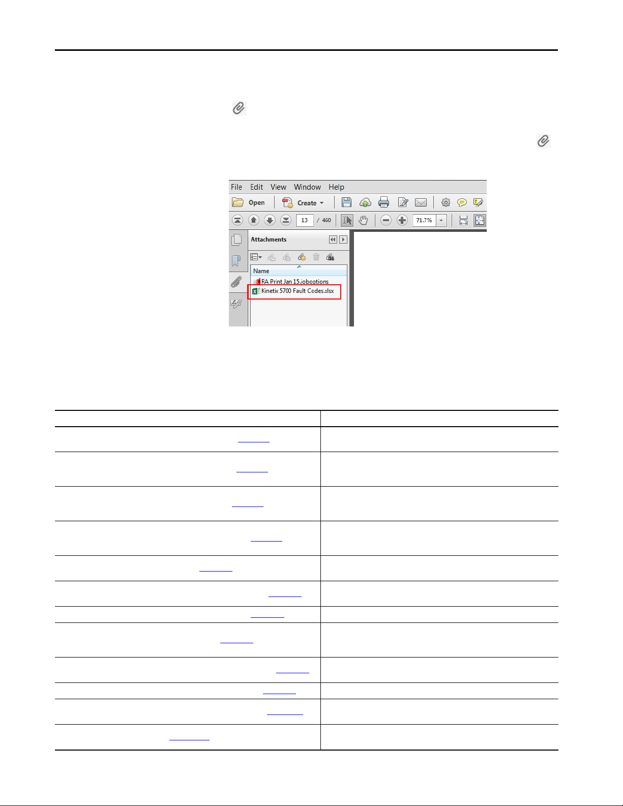
Access the Attachments
Additional Resources
Table 2 - Additional Resources
The Microsoft Excel spreadsheet that is attached to this publication contains
fault code descriptions. To use the spreadsheet file, click the Attachments link
, right-click the spreadsheet file, and save the file to your computer.
If the PDF file opens in a browser and you don't see the Attachments link ,
download the PDF file and reopen the file with the Adobe Acrobat Reader
application.
These documents contain additional information concerning related products
from Rockwell Automation.
Resource Description
Kinetix Rotary Motion Specifications Technical Data, publication KNX-TD001
Kinetix Linear Motion Specifications Technical Data, publication KNX-TD002
Kinetix Servo Drives Specifications Technical Data, publication KNX-TD003
Kinetix Motion Accessories Specifications Technical Data, publication KNX-TD004
AC Line Filter Installation Instructions, publication 2198-IN003
Kinetix 5700 Regenerative Bus Supply Installation Instructions, publication 2198-IN014
Kinetix 5700 Capacitor Modules Installation Instructions, publication 2198-IN008 Provides information on installing and wiring the Kinetix 5700 capacitor modules.
Replacement Fan Kit Installation Instructions, publication 2198-IN015
Kinetix 5700 DC-bus Conditioner Module Installation Instructions, publication 2198-IN016
Kinetix 5700 Shunt Passive Modules Installation Instructions, publication 2198-IN011 Provides information on installing and wiring Kinetix 5700 passive shunts.
Kinetix 5700 Safe Monitor Functions Safety Reference Manual, publication 2198-RM001
iTRAK System User Manual, publication 2198T-UM001
Provides product specifications for Kinetix VP (Bulletin VPL, VPC, VPF, and VPS),
MP-Series™ (Bulletin MPL, MPM, MPF, and MPS), and HPK-Series™ rotary motors.
Provides product specifications for Bulletin MPAS and MPMA linear stages,
Bulletin VPAR, MPAR, and MPAI electric cylinders, LDAT-Series linear thrusters, and
LDC-Series™ linear motors.
Provides product specifications for Kinetix Integrated Motion over the EtherNet/IP
network, Integrated Motion over sercos interface, EtherNet/IP networking, and
component servo drive families.
Provides product specifications for Bulletin 2090 motor and interface cables, lowprofile connector kits, drive power components, and other servo drive accessory
items.
Provides information on installing and wiring the Kinetix 5500 and Kinetix 5700 AC
line filters.
Provides information on installing and wiring the Kinetix 5700 regenerative bus
supply.
Provides information on removal and replacement of cooling fans used in 2198RPxxx regenerative bus supplies and 2198-S263-ERSx and 2198-S312-ERSx single-
axis inverters.
Provides information on installing and wiring the Kinetix 5700 DC-bus conditioner
module.
Provides a description of integrated stopping functions and safe monitoring
functions with a GuardLogix® controller and Kinetix 5700 servo drives.
Provides information on installing the Kinetix 5700 iTRAK power supply with an
iTRAK system and programming the iTRAK system.
Rockwell Automation Publication 2198-UM002G-EN-P - February 2019 13
Page 14

Preface
Table 2 - Additional Resources (continued)
Resource Description
1321 Power Conditioning Products Technical Data, publication 1321-TD001
8720MC Regenerative Power Supply Installation Manual, publication 8720MC-RM001
System Design for Control of Electrical Noise Reference Manual, publication GMC-RM001
Kinetix Motion Control Selection Guide, publication KNX-SG001
Kinetix 5700 Drive Systems Design Guide, publication KNX-RM010
Rockwell Automation Product Selection
website http://www.rockwellautomation.com/global/support/selection.page
Motion Analyzer System Sizing and Selection Tool
website https://motionanalyzer.rockwellautomation.com/
Product Certifications website, rok.auto/certifications
Motor Nameplate Datasheet Entry for Custom Motor Applications Application Technique,
publication 2198-AT002
Vertical Load and Holding Brake Management Application Technique,
publication MOTION-AT003
Motion System Tuning Application Technique, publication MOTION-AT005 Provides information on tuning a Kinetix drive system.
Integrated Motion on the EtherNet/IP Network Configuration and Startup User Manual,
publication MOTION-UM003
Integrated Motion on the EtherNet/IP Network Reference Manual,
publication MOTION-RM003
GuardLogix 5570 Controllers User Manual, publication 1756-UM022
GuardLogix 5580 Controllers User Manual, publication 1756-UM543
Compact GuardLogix 5370 Controllers User Manual, publication 1769-UM022
Compact GuardLogix 5380 Controllers User Manual, publication 5069-UM001
GuardLogix 5570 and Compact GuardLogix 5370 Controller Systems Safety Reference
Manual, publication 1756-RM099
GuardLogix 5580 and Compact GuardLogix 5380 Controller Systems Safety Reference
Manual, publication 1756-RM012
ControlFL ASH Firmware Upgrade Software User Manual, publication 1756-UM105 For ControlFLASH™ information not specific to any drive family.
Rockwell Automatio n Industrial Automation Glossary, publication AG-7 .1
Industrial Automation Wiring and Grounding Guidelines, publication 1770-4.1
Provides information on typical use cases, specifications, terminations, and
dimensions of Bulletin 1321 line reactors.
Provides information on installing, wiring, and startup for the 8720MC
regenerative power supply with 380…460V AC operation.
Provides information, examples, and techniques designed to minimize system
failures caused by electrical noise.
Overview of Kinetix ser vo drives, motors, actuators, and motion accessories
designed to help make initial decisions for the motion control products best suited
for your system requirements.
System design guide to select the required (drive specific) drive module, power
accessory, feedback connector kit, and motor cable catalog numbers for your
Kinetix 5700 drive system.
Online product selection and system configuration tools, including AutoCAD (DXF)
drawings.
Comprehensive motion application sizing tool used for analysis, optimization,
selection, and validation of your Kinetix Motion Control system.
Provides declarations of conformity, certificates, and other certification details.
Provides information on the use of nameplate data entry for custom induction
motors and permanent-magnet motors that are used in applications with
Kinetix 5700 servo drives.
Provides information on vertical loads and how the servo motor holding-brake
option can be used to help keep a load from falling.
Provides information on configuring and troubleshooting your ControlLogix® and
CompactLogix™ EtherNet/IP network modules.
Provides information on the AXIS_CIP_DRIVE attributes and the Studio 5000 Logix
Designer application Control Modes and Methods.
Provides information on how to install, configure, program, and use ControlLogix
controllers and GuardLogix controllers in Studio 5000 Logix Designer projects.
Provides information on how to install, configure, program, and use CompactLogix
and Compact GuardLogix controllers.
Provides information on how to achieve and maintain Safety Integrity Level (SIL)
and Performance Level (PL) safety application requirements for GuardLogix and
Compact GuardLogix controllers.
A glossary of industrial automation terms and abbreviations.
Provides general guidelines for installing a Rockwell Automation industrial system.
You can view or download publications at
http://www.rockwellautomation.com/global/literature-library/overview.page
14 Rockwell Automation Publication 2198-UM002G-EN-P - February 2019
.
Page 15

Chapter 1
Start
Use this chapter to become familiar with the Kinetix® 5700 drive system and
obtain an overview of installation configurations.
Top ic Pa ge
Kinetix 5700 Servo Drives Series Change 16
About the Kinetix 5700 Servo Drive System 17
DC-bus Power Supply Input Power Configurations 19
Regenerative Bus Supply Input Power Configurations 23
8720MC-RPS Power Supply Input Power Configuration 28
Motor and Auxiliary Feedback Configurations 29
Typical Communication Configurations 30
Functional Safety Configurations 33
Catalog Number Explanation 37
Agenc y Compliance 39
Rockwell Automation Publication 2198-UM002G-EN-P - February 2019 15
Page 16

Chapter 1 Start
Kinetix 5700 Servo Drives Series Change
Single-axis and dual-axis inverters, catalog numbers 2198-xxxx-ERS3
(series B), include an enhancement that is not included in series A drives, but
that is included in 2198-xxxx-ERS4 drives.
• The drive-based (Monitored SS1 and Timed SS1) stopping functions
and controller-based monitoring functions apply to the
2198-xxxx-ERS4 drives
• The drive-based Timed SS1 stopping function and STO with
configurable delay applies to the 2198-xxxx-ERS3 (series B) drives
• When catalog number 2198-xxxx-ERS3 appears in this publication
without series designation, the topic applies to series A and B drives
Table 3 - Integrated Functional Safety Support
Integrated Safety Over the
EtherNet/IP™ Network
Drive-based stopping functions
Controller-based stopping functions
Controller-based monitoring functions
Safety feedback function Safety Feedback Interface (SFX)
Integrated STO mode Safe Torque-off (STO)
(1) Where a ControlLogix or CompactLogix (non-safety) controller is specified, a GuardLogix or Compact GuardLogix controller is backwards compatible. Also, GuardLogix 5580 and Compact GuardLogix
5380 controllers are backwards compatible with GuardLogix 5570 and Compact GuardLogix 5370 controllers.
Safety Func tion
Timed Safe Stop 1 (SS1)
Monitored Safe Stop 1 (SS1)
• Monitored Safe Stop 1 (SS1)
• Safe Stop 2 (SS2)
• Safe Operational Stop (SOS)
• Safely Limited Speed (SLS)
• Safety Limited Position (SLP)
• Safe Direction (SDI)
Dual-axis Inverters
Cat. No.
2198-Dxxx-ERS3 (series B)
2198-Dxxx-ERS4
2198-Dxxx-ERS4 2198-Sxxx-ERS4
2198-Dxxx-ERS4 2198-Sxxx-ERS4
2198-Dxxx-ERS3 2198-Sxxx-ERS3
Single-axis Inverters
Cat. No.
2198-Sxxx-ERS3 (series B)
2198-Sxxx-ERS4
Minimum Controller
Required
• GuardLogix® 5580
• CompactLogix™ 5380
• ControlLogix® 5570
• CompactLogix 5370
(1)
16 Rockwell Automation Publication 2198-UM002G-EN-P - February 2019
Page 17

Start Chapter 1
About the Kinetix 5700 Servo Drive System
Table 4 - Kinetix 5700 Drive System Overview
Drive System
Component
Kinetix 5700 DC-bus
Power Sup ply
Kinetix 5700
Regenerative Bus
Supply
Kinetix 5700 Singleaxis Servo Drives
Kinetix 5700 Dualaxis Servo Drives
Kinetix 5700 iTRAK
Power Sup ply
Kinetix 5700
Capacitor Module
Kinetix 5700
Extension Module
Kinetix 5700 DC-bus
Conditioner Module
8720MC Regenerative
Power Sup ply
Shared-bus
Connector Kits
DSL Feedback
Connector Kit
Universal Feedback
Connector Kit
Hiperface to DSL
Converter Kit
Cat. No. Description
2198-Pxxx
2198-RPxxx
2198-Sxxx-ERS3
2198-Sxxx-ERS4
2198-Dxxx-ERS3
2198-Dxxx-ERS4
2198T-W25K-ER DC-DC converter that generates DC-bus power for iTRAK® systems.
2198-CAPMOD-2240
2198-CAPMOD-DCBUS-IO
2198-DCBUSCOND-RP312
8720MC-RPSxxx
2198-TCON-24VDCIN36
2198-xxxx-P-T
2198-BARCON-xxDCAC100
2198T-W25K-P-IN
2198T-W25K-P-T
2198-BARCON-xxDC200
2198-KITCON-ENDCAP200
2198-KITCON-DSL
2198-K57CK-D15M
2198-H2DCK
(series B or later)
The Kinetix 5700 drive modules are zero-stacked and use the shared-bus
connection system to extend power from one drive module to another. Systems
are designed to support Integrated Motion over the EtherNet/IP network.
Converter power supply with 400V-class (three-phase) AC input. Provides power in a range of 7…46 kW and
10.5…69.2 A output current. Systems typically consist of one module, however, up to three modules in parallel is
possible. Parallel modules increase available power for Bulletin 2198 single-axis and dual-axis inverters.
Regenerative bus supply with 400V-class (three-phase) AC input provides continuous output power and current to
Bulletin 2198 single-axis and dual-axis inverters for applications with requirements in the range of 24…140 kW and
35…207 A, output current.
Single-axis inverters with current ratings up to 192 A rms. Drives feature TÜV Rheinland certified safe torque-off
function with hardwired and integrated safety connection options, PL e and SIL 3 safety ratings, and support for DSL,
Hiperface, and Heidenhain EnDat encoder feedback. 2198-Sxxx-ERS3 (series B) drives also support Timed SS1 drivebased stopping functions.
Single-axis inverters with the same power structure and encoder feedback support as -ERS3 inverters, plus support for
Monitored SS1 and Timed SS1 drive-based stopping functions. Also, support for controller-based safe stop and safe
monitor functions over the EtherNet/IP network.
Dual-axis inverters with current ratings up to 23 A rms. Drives feature TÜV Rheinland certified safe torque-off function
with hardwired and integrated safety connection option s, PL e and SIL 3 safety ratings, and support for DSL, Hiperface,
and Heidenhain EnDat encoder feedback. 2198-Dxxx-ERS3 (series B) drives also support Timed SS1 drive-based
stopping functions.
Dual-axis inverters with the same power struc ture and encoder feedback support as -ERS3 inverters, plus support for
Monitored SS1 and Timed SS1 drive-based stopping functions. Also, support for controller-based safe stop and safe
monitor functions over the EtherNet/IP network.
Use for energy storage, external active-shunt connection, and to extend the DC-bus voltage to another inver ter cluster.
Modules are zero-stacked with servo drives and use the shared-bus connection system to extend the ex ternal DC-bus
voltage in applications up to 104 A. Can parallel with itself or with another accessory module for up to 208 A with
required 2198-KITCON-CAPMOD2240 kit that includes flexible bus-bars.
The extension module, paired with a capacitor module or DC-bus conditioner module, is used to extend the DC-bus
voltage to another inverter cluster in systems with ≥104 A current and up to 208 A.
Decreases the voltage stress on insulation components in an inverter system and used to extend the DC-bus voltage to
another inverter cluster. Modules are zero-stacked with servo drives and use the shared-bus connection system to
extend the external DC-bus voltage in applications up to 104 A. Can parallel with itself or with another accessory
module for up to 208 A with required 2198-KITCON-DCBUSCOND kit that includes flexible bus-bars.
Sinusoidal PWM converter that can control the increase of DC-bus voltage and perform continuous power generation
for one or more servo drives in multi-axis DC common-bus configurations.
24V input wiring connectors, T-connectors, and bus-bars for most Kinetix 5700 drive modules that use the 24V sharedbus connection system (optional).
24V input wiring connector, T-connector, and bus-bar for the iTRAK motor module and other select Kinetix 5700 drive
modules that use the 24V shared-bus connection system (optional).
DC-bus links (55, 85, 100, and 220 mm) and end caps for the DC-bus shared-bus connection system (required and
included with each respective drive module). DC-bus links (165, 275, and 440 mm) are optional and do not ship with
any modules.
Replacement DSL motor feedback connector kit with 2-pin connector plug and grounding plate inside the connector
housing. Supports 400V-class Kinetix VP rotary motors. Included with 2090-CSxM1DE motor cables. Must be purchased
separately when used with 2090-CSxM1DG motor cables.
Universal feedback connector kit for motor and auxiliary feedback connections with the 15-pin connector plug and
grounding plate inside the connector housing. Supports 400V-class MP-Series™ and HPK-Series™ rotary motors, MPSeries linear actuators, LDAT-Series linear thrusters, and LDC-Series™ linear motors.
Provides Hiperface-to-DSL feedback conversion for use with compatible 400V-class motors and actuators.
Rockwell Automation Publication 2198-UM002G-EN-P - February 2019 17
Page 18

Chapter 1 Start
Table 4 - Kinetix 5700 Drive System Overview (continued)
Drive System
Component
Kinetix 5700 System
Mounting Toolkit
Kinetix 5700 Cable
Clamp Spacer Kit
Encoder Output
Module
Logix 5000™
Controller Platform
Studio 5000®
Environment
Rotary Servo Motors
Linear Actuators
Linear Motors LDC-Series Compatible motors include LDC-Series iron-core (400V-class) linear motors.
Induction Motors N/A Induction motors with open-loop frequency control and closed-loop control are supported.
Cables
AC Line Filters
Line Reactors 1321-3Rxx-x
AC Contac tor
24V DC Power Supply 1606-XLxxx Bulletin 1606 24V DC power supply for control circuitry, digital inputs, safety, and motor brake.
External Passive
Shunt Resistors
External Active
Shunts
Cat. No. Description
2198-K5700-MOUNTKIT Use to position the drive modules and identify drill-holes for mounting your Kinetix 5700 servo drive system.
2198-K5700-CLAMPSPACER Replacement cable clamp spacers for 2198-Dxxx-ERSx dual-axis inverters.
2198-ABQE
Bulletin 1769
Bulletin 5069
1756-EN2T module
1756-EN2TR module
1756-EN3TR module
N/A
Kinetix VP Compatible motors include 400V-class Bulletin VPL, VPC, VPF, and VPS ser vo motors.
MP-Series Compatible motors include 400V-class Bulletin MPL, MPM, MPF, and MPS servo motors.
HPK-Series Compatible motors include 460V and 400V-class HPK-Series asynchronous servo motors.
Kinetix VP, MP-Series,
LDAT-Series
2090-CSxM1DE-xxAxxx
2090-CSxM1DG-xxAxxx
2090-CFBM7DF-CEAxxx Bulletin 2090 motor feedback cables for MP-Series motors and actuators with Stegmann Hiperface encoders.
2090-CPxM7DF-xxAxxx Bulletin 2090 motor power/brake cables for MP-Series motors and actuators.
2090-XXNFMF-Sxx
2090-CFBM7DF-CDAFxx
2198T-CHBFLS8-12AAxx Bulletin 2198T power cables for iTRAK power supply to iTRAK motor modules.
1585J-M8CBJM-x Ethernet cables are available in standard lengths. Shielded cable is required to meet EMC specifications.
2198-DB20-F, 2198-DB42-F,
2198-DB80-F, 2198-DB290-F
2198-DBR20-F, 2198-DBR40-F,
2198-DBR90-F, 2198-DBR200-F
100-Cxxxxx
100-Dxxxxx
100-Exxxxx
2198-R014, 2198-R031,
2198-R127, 2198-R004
N/A
The Allen-Bradley® encoder output module is a DIN-rail mounted EtherNet/IP network-based standalone module
capable of outputting encoder pulses to a customer-supplied peripheral device (cameras, for example, used in linescan vision systems).
Integrated Motion on the EtherNet/IP network in CompactLogix 5370 and CompactLogix 5380 controllers and
Integrated Safety in Compact GuardLogix 5370 and Compact GuardLogix 5380 controllers. Linear, device-level ring
(DLR), and star topology is supported.
EtherNet/IP network communication modules for use with ControlLogix 5570, ControlLogix 5580, GuardLogix 5570,
and GuardLogix 5580 controllers. Linear, device-level ring (DLR), and star topology is supported.
Studio 5000 Logix Designer® application, version 26.00 or later, provides support for programming, commissioning,
and maintaining the CompactLogix, ControlLogix, and GuardLogix controller families.
Compatible actuators include 400V-class Bulletin MPAS linear stages, Bulletin VPAR, MPAR, and MPAI electric cylinders,
and LDAT-Series linear thrusters.
Bulletin 2090 single cable for motor power, feedback, and 24V DC brake power with Kinetix VP motors. Feedback
conductors are wired to the 2198-KITCON-DSL feedback connector kit.
Bulletin 2090 single cable for motor power, feedback, and 24V DC brake power with Kinetix VP motors. 2090-CSxM1DG
cables have flying-lead feedback conductors for connection to a customer-supplied 2198-KITCON-DSL feedback
connector kit.
Bulletin 2090 standard and continuous-flex feedback cables that include additional conductors for use with
incremental and EnDat encoders.
Bulletin 2198 three-phase AC line filters are required to meet CE and are available for use with DC-bus power supplies.
Use 2198-DBxx-F filters as field replacements in existing installations that use DC-bus power supplies with inverter
ground jumpers installed. Select 2198-DBRxx-F filters for all new systems and remove all inverter ground jumpers.
Bulletin 2198 three-phase AC line filters are required to meet CE and available for use with DC-bus power supplies and
regenerative bus supplies. Select 2198-DBRxx-F filters for all new systems and remove all inverter ground jumpers.
Bulletin 1321 line reactors help keep equipment running longer by absorbing many of the power line disturbances that
can shut down your power supply. For 2198-RPxxx regenerative bus supplies, line reactors can significantly reduce the
amount of circulating currents between the integrated LC filter and other devices on the common AC power source.
The AC three-phase contactor control string must be wired in series with the contactor-enable relay at the CED
connector to make sure that three-phase power is removed under various fault conditions to protect the power supply.
Bulletin 2198 external passive-shunt resistors for use when the DC-bus power supply internal shunt capability is
exceeded. Not for use with regenerative bus supplies.
External active shunts from Rockwell Automation Encompass™ partner, Powerohm Resistors, Inc., are available for
connecting to Bulletin 2198 DC-bus power supplies and regenerative bus supplies. See External Active-shunt
Connections on page 183 for catalog numbers.
18 Rockwell Automation Publication 2198-UM002G-EN-P - February 2019
Page 19
Start Chapter 1
Bulletin 2198
Shunt Module
(optional component)
Magnetic Contactor (M1) Control String
1606-XLxxx
24V DC Control, Digital Inputs,
and Motor Brake Power (customer-supplied)
AC Input Power
Kinetix 5700 Servo Drive System
(front view)
Bulletin 2198 shared-bus connection system for
DC-bus and 24V DC control power.
Kinetix 5700 Servo Drive System
(top view)
Line Disconnect
Device
324…528V AC
Three-phase Input Power
Circuit
Protection
Magnetic (M1)
Contac tor
Bonded Cabinet
Ground Bus
2198-DBRxx-F
AC Line Filter
(required for CE)
Converter Digital Inputs
Inverter Digital Inputs
Shared DC-bus Power
Shared 24V Control Power
(24V shared-bus connection system is optional)
DC-bus
Power Supply
Single-axis
Inverter
Dual-axis
Inverters
Capacitor
Module
DC-bus Power Supply Input Power Configurations
A single 2198-Pxxx DC-bus (converter) power supply can supply the
Kinetix 5700 drive system with 458…747V shared DC-bus power (7…46 kW).
For additional output power (kW) you can install two or three 2198-P208
DC-bus power supplies. You can also extend the DC-bus to additional inverter
clusters via accessory modules.
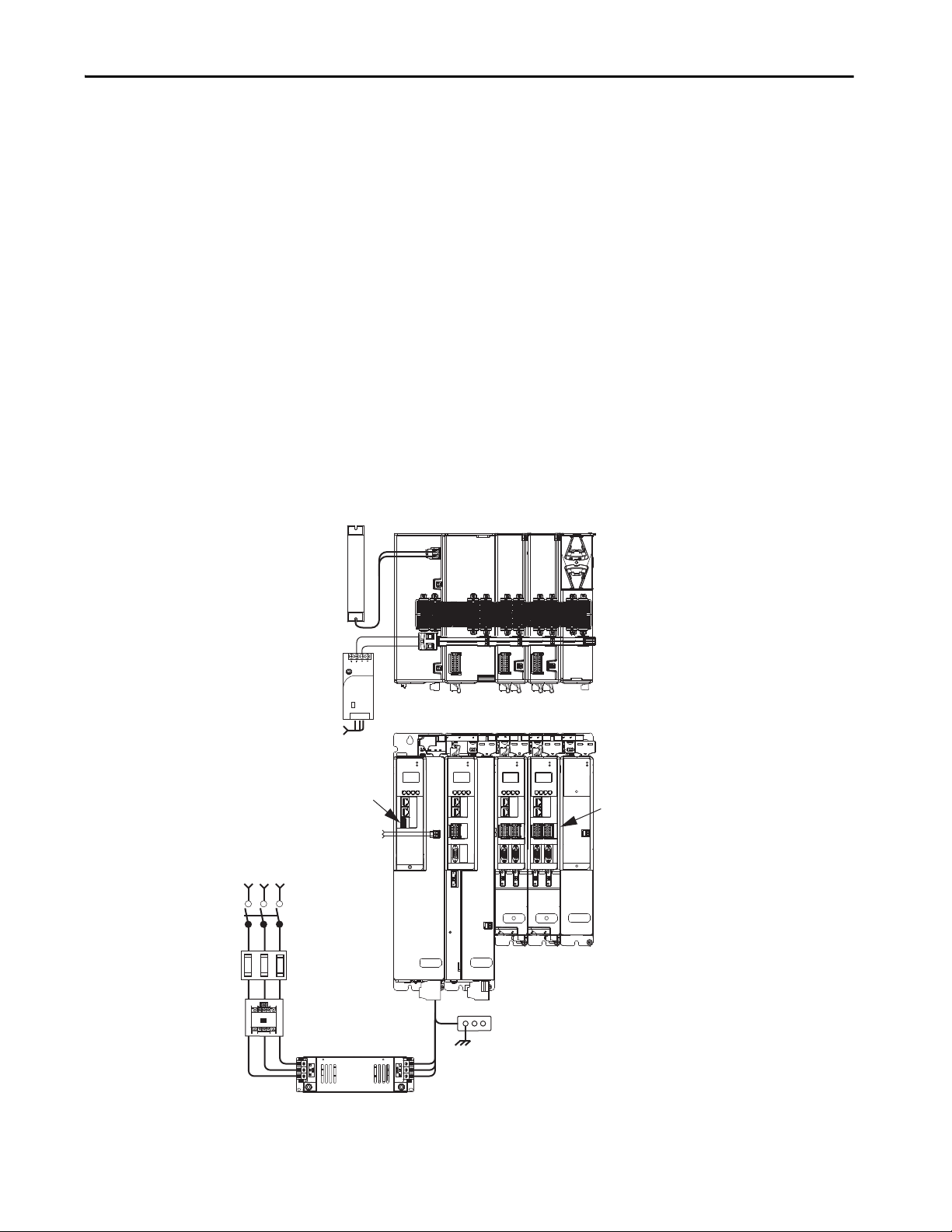
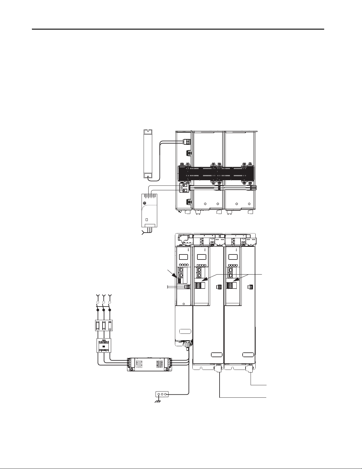
Typical DC-bus Power Supply Configuration Example
In this multi-axis example, AC input power is fed to the DC-bus (converter)
power supply. One single-axis (inverter) module and two dual-axis (inverter)
modules support five axes of motion. The DC-bus power supply is mounted
on the far left and the inverters are positioned on the right, but the reverse
mounting order (right to left) is also possible.
Digital inputs are wired to sensors and the control circuitry at the IOD
connectors. The contactor-enable relay protects the DC-bus power supply in
the event of shutdown fault conditions.
Figure 1 - Typical DC-bus Power Supply Installation
SH
DC+
Allen-Bradley
1606-XL
Power Supply
Input
19
SB+/NC
S1A
SCA
S2A
SBNC
NC
NC
16
8
19
19
SB+/NC
SB+/NC
S1A
S1A
SCA
SCA
S2A
S2A
SB-
SB-
NC
NC
NC
NC
NC
NC
16
16
8
8
MOD
MOD
NET
MOD
NET
MOD
NET
MOD
NET
DC BUS
2
1
I/O
1
6
5
10
UFB
D+
D-
MF
-
MBRK
+
2
1
1
4
I/O
2
2
1
1
I/O-A
I/O-B
I/O-A
I/O-B
1
6
1
6
1
6
1
6
MODULE
D+
D-
510
UFB-A UFB-B
510
D+
D-
STATUS
510
510
UFB-A UFB-B
D+D-D+
D-
MF-A MF-B MF-A MF-B
Rockwell Automation Publication 2198-UM002G-EN-P - February 2019 19
Page 20
Chapter 1 Start
DC+
SH
DC+
SH
1606-XL
Power Supply
Input
Allen-Bradley
MOD
NET
MOD
NET
MOD
NET
2
1
1
4
I/O
2
1
2
1
UFB-A UFB-B
UFB-A UFB-B
D+D-D+
D-
D+
D-
MF-A MF-B MF-A MF-B
D+
D-
DC+
SH
MOD
NET
2
1
1
4
I/O
MOD
NET
2
1
1
4
I/O
MOD
DC BUS
MODULE
STATUS
19
8
16
19
8
16
1
I/O-A
6
510
1
I/O-B
6
510
1
I/O-A
6
510
1
I/O-B
6
510
SB+/NC
NC
S1A
SCA
S2A
SBNC
NC
SB+/NC
NC
S1A
SCA
S2A
SBNC
NC
MOD
NET
2
1
1
I/O
6
5
10
MBRK
+
-
21mm (4 AWG-250 kcmil)
15-20 Nm (132-177 lbin)
2
W V U
19
8
16
SB+/NC
NC
S1A
SCA
S2A
SBNC
NC
Bulletin 2198
Shunt Module
(optional component)
1606-XLxxx
24V DC Control Power
(customer-supplied)
AC Input Power
Kinetix 5700 Ser vo Drive System
(front view)
Kinetix 5700 Servo
Drive System (top view)
Circuit
Protection
Bonded Cabinet
Ground Bus
1321-3R80-B
Line Reactors
(required components)
2198-P208 DC-bus Power Supplies
Single-axis Inverter
Dual-axis Inverters
Capacitor
Module
Bulletin 2198 shared-bus
connection system for DC-bus
and 24V DC control power.
Shared DC-bus Power
Shared 24V Control Power
(24V shared-bus connection
system is optional)
Magnetic Contactor
(M1) Control String
Line Disconnect
Device
324…528V AC
Three-phase
Input Power
Magnetic (M1)
Contac tor
2198-DBR200-F
AC Line Filter
(required for CE)
Circuit
Protection
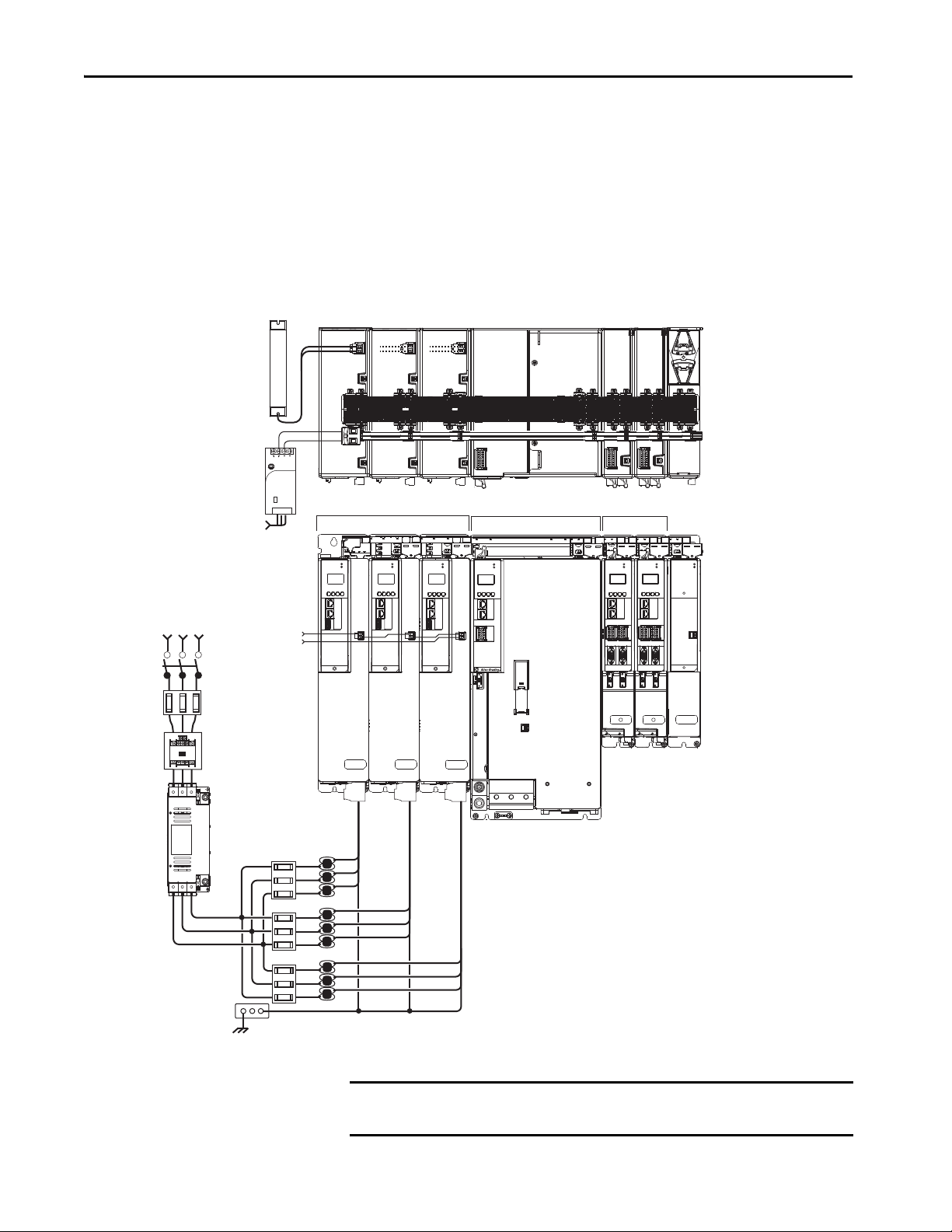
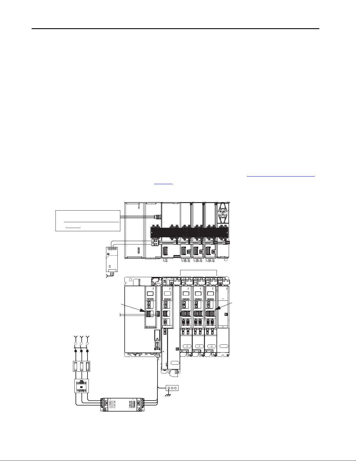
Multiple DC-Bus Power Supply Configuration Example
In this example, three DC-bus (converter) power supplies all receive AC input
power and feed the inverter modules for increased output power.
Contactor enable relays from each of the DC-bus power supplies are wired in
series to protect the DC-bus power supply in the event of shutdown fault
conditions.
Figure 2 - Multiple DC-bus Power Supply Installation
IMPORTANT When two or three DC-bus power supplies are wired together in the same
drive cluster, they must all be catalog number 2198-P208.
20 Rockwell Automation Publication 2198-UM002G-EN-P - February 2019
Page 21
Start Chapter 1
Kinetix 5700 Servo Drives
Cluster 1 (front view)
Bonded Cabinet
Ground Bus
Kinetix 5700 Extended Servo Drives
Cluster 2 (front view)
DC-bus Extension
Shared DC-bus and
24V DC Control Power
Circuit
Protection
1321-3R80-B
Line Reactors
(required components)
2198-P208 DC-bus Power Supplies
Single-axis
Inverter
Dual-axis
Inverters
Capacitor
Module
Extension
Module
Capacitor
Module
Extension
Module
Dual-axis Inverters
Bulletin 2198 Shared-bus
Connection System
(24V shared-bus connection
system is optional)
Magnetic Contactor
(M1) Control String
Line Disconnect
Device
324…528V AC
Three-phase
Input Power
Magnetic (M1)
Contac tor
2198-DBR200-F
AC Lin e Filter
(required for CE)
DC-bus Extension
ATT EN TI ON : Circuit protection can
be added after the power supply
cluster to help protect converters and
inverters from damage in the event of
a DC-bus cable short-circuit.
Circuit
Protection
Extended DC-bus Configuration Example
In this example, two drive clusters in the same cabinet are connected by the
same 458…747V DC bus voltage. Kinetix 5700 accessory modules provide
connection points for the DC-bus at the end of cluster 1 and the beginning of
cluster 2. The Kinetix 5700 servo drive system is capable of up to 208 A
DC-bus current. Two accessory modules are needed when the DC-bus system
current exceeds 104 A. See Accessory Module Selection
information on the when accessory modules are required.
Figure 3 - Extended DC-bus Installation
MOD
MOD
MOD
MOD
MOD
MOD
NET
NET
NET
DC BUS
NET
MOD
NET
NET
on page 59 for more
MOD
NET
MOD
NET
2
1
1
4
I/O
MOD
NET
2
1
1
4
I/O
2
2
1
1
I/O-A
I/O-B
I/O-A
1
6
1
6
1
MODULE
510
510
510
STATUS
UFB-A UFB-B
UFB-A UFB-B
D+
D+
D-
D-
MF-A MF-B
MF-A MF-B MF-A MF-B
MOD
NET
2
1
1
4
I/O
2
2
1
I/O-B
6
1
510
D+
D-
1
I/O-A
I/O-B
I/O-A
6
1
6
1
6
1
6
1
510
510
510
510
UFB-A UFB-B
UFB-A UFB-B
D+
D+
D+
D+
D-
D-
D-
D-
MF-A MF-B
I/O-B
6
2
1
I/O-A
I/O-B
1
6
1
6
510
510
UFB-A UFB-B
D+D-D+
D+
D-
D-
MF-A MF-B MF-A MF-B
2
1
1
510
I/O-A
UFB-A UFB-B
2
1
I/O-B
I/O-A
I/O-B
6
1
6
1
6
1
6
510
510
510
UFB-A UFB-B
D+
D+
D+
D-
D-
D-
MF-A MF-B
MOD
NET
2
1
I/O-A
I/O-B
1
6
1
6
510
510
UFB-A UFB-B
D+D-D+
D-
MF-A MF-B MF-A MF-B
D+
D-
2
1
1
510
I/O-A
UFB-A UFB-B
MOD
NET
I/O-B
6
1
6
510
D+
D-
MOD
DC BUS
MODULE
STATUS
MOD
NET
2
1
I/O
1
6
5
10
UFB
D+
D-
MF
-
MBRK
+
IMPORTANT When two or three DC-bus power supplies are wired together in the same
drive cluster, they must all be catalog number 2198-P208.
Rockwell Automation Publication 2198-UM002G-EN-P - February 2019 21
Page 22
Chapter 1 Start
2
1
16
I/O
510
–
iPS RDY
+
MOD–
NET–
1
2
3
4
5
6
7
8
9
10
MOD
NET
2
1
1
4
I/O
2
1
16
I/O
510
–
iPS RDY
+
MOD–
NET–
1
2
3
4
5
6
7
8
9
10
SH
DC+
1606-XL
Power Supply
Input
Allen-Bradley
Bulletin 2198
Shunt Module
(optional component)
Magnetic Contactor
(M1) Control String
1606-XLxxx
24V DC Control, Digital Inputs,
and iTRAK Motor Module Control Power
(customer-supplied)
AC Input Power
Kinetix 5700 iTRAK System
(front view)
Kinetix 5700 iTRAK System
(top view)
Line Disconnect
Device
324…528V AC
Three-phase
Input Power
Circuit
Protection
Magnetic (M1)
Contac tor
Bonded Cabinet
Ground Bus
2198-DBRxx-F
AC Lin e Filter
(can be required for CE)
Converter Digital Inputs
iTRAK Motor Modules
DC-bus
Power Supply
iTRAK
Power Supply
iTRAK
Power Supp ly
iTRAK Motor Modules
iTRAK Power Supply
Digital Inputs
Shared-bus connection system for
DC-bus and 24V DC control power.
Shared DC-bus Power
Shared 24V Control Power
(1)
(24V shared-bus connection system
is optional)
2198T-CHBFLS8
Motor Power
Cables
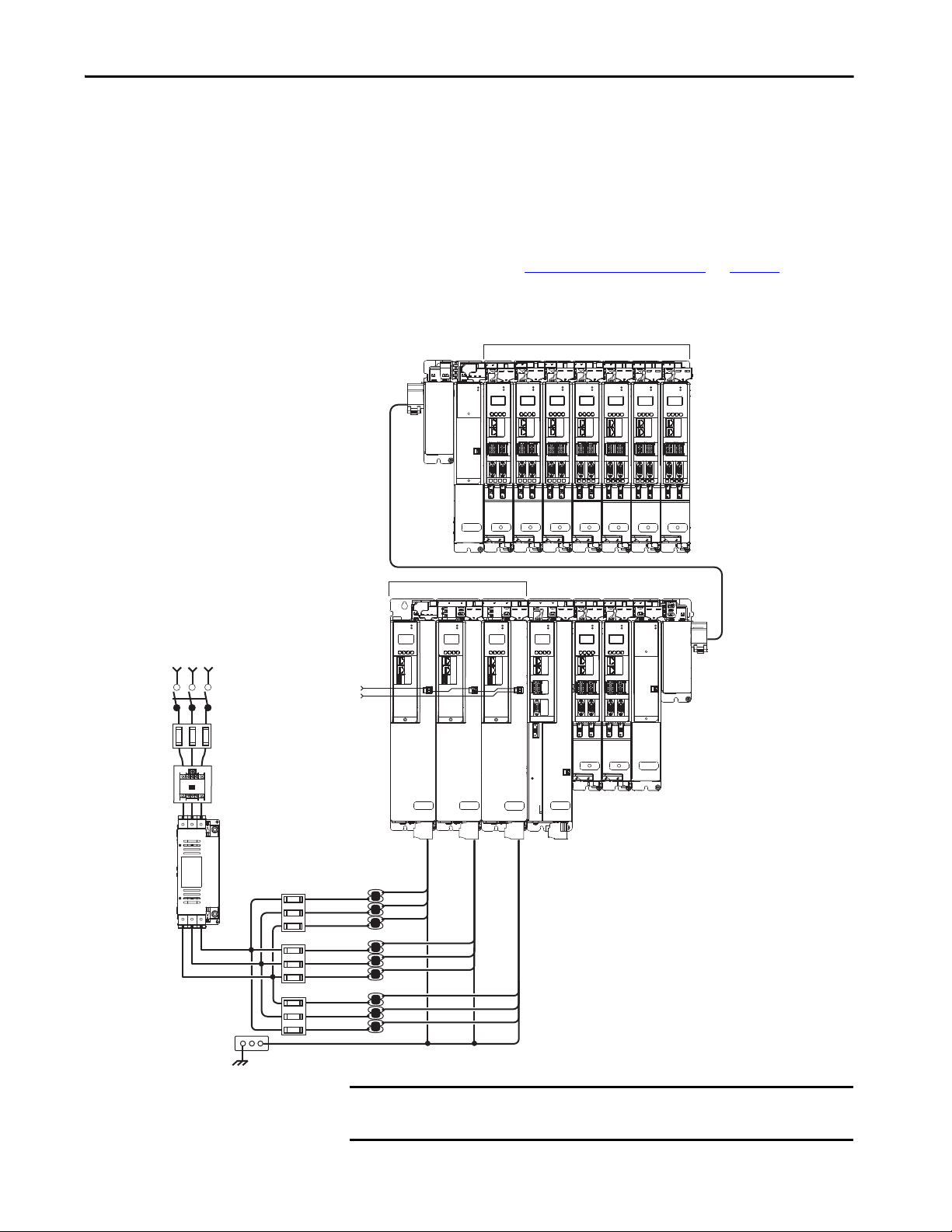
iTRAK Power Supply Configuration Example
In this example, AC input power is fed to the DC-bus (converter) power
supply. Two iTRAK power supplies support up to 40 iTRAK motor modules,
depending on cable lengths and iTRAK motor-module power consumption.
Digital inputs are wired to sensors and the control circuitry at the IOD
connectors. The contactor-enable relay protects the DC-bus power supply in
the event of shutdown fault conditions.
Figure 4 - Typical iTRAK Power Supply Installation
(1) If total control power current exceeds 16 A, a second input connector (catalog number 2198T-W25K-P-IN) can be added to the
leftmost iTRAK power supply.
22 Rockwell Automation Publication 2198-UM002G-EN-P - February 2019
Page 23
Start Chapter 1
1606-XL
Power Supply
Input
Allen-Bradley
MOD
NET
MOD
NET
MOD
NET
1
I/O
6
5
10
2
1
2
1
2
1
1
I/O-A
6
510
1
I/O-B
6
510
UFB
UFB-A UFB-B
UFB-A UFB-B
D+D-D+
D-
D+
D-
MF-A MF-B MF-A MF-B
D+
D-
MBRK
+
-
DC+
D+
D-
MF
SB+/NC
NC
19
8
16
19
8
16
19
8
16
1
I/O-A
6
510
1
I/O-B
6
510
S1A
SCA
S2A
SBNC
NC
SB+/NC
NC
S1A
SCA
S2A
SBNC
NC
SB+/NC
NC
S1A
SCA
S2A
SBNC
NC
MOD
NET
2
1
1
I/O
6
5
10
OK+
OK–
EN–
EN+
DC–
MOD
DC BUS
MODULE
STATUS
MOD
NET
2
1
UFB-A UFB-B
D+
D-
MF-A MF-B
D+
D-
1
I/O-A
6
510
1
I/O-B
6
510
19
8
16
SB+/NC
NC
S1A
SCA
S2A
SBNC
NC
Active Shunt (optional component)
See External Active-shunt Connections
on page 183
for more information.
Magnetic Contactor (M1) Control String
1606-XLxxx
24V DC Control, Digital Inputs, and
Motor Brake Power (customer-supplied)
AC Input Power
Kinetix 5700 Servo Drive System
(front view)
Shared-bus connection system for DC-bus and
24V DC control power.
Kinetix 5700 Ser vo Drive System
(top view)
Line Disconnect
Device
324…506V AC
Three-phase Input Power
Circuit
Protection
Magnetic (M1)
Contac tor
Bonded Cabinet
Ground Bus
Converter Digital Inputs
Inverter Digital Inputs
Shared DC-bus Power
Shared 24V Control Power
(24V shared-bus connection system is optional)
Single-axis
Inverter
Dual-axis Inverters
Regenerative Bus Supply
(1)
DC-bus Conditioner
Module
2198-DBRxx-F
AC Lin e Filter
(required for CE)
Regenerative Bus Supply Input Power Configurations
The 2198-RPxxx regenerative bus supply (24…140 kW) provides full-line
motoring and regenerative power to and from the Kinetix 5700 drive system.
In addition, you can extend the DC-bus voltage to additional inverter clusters
via accessory modules.
Typical Regenerative Bus Configuration Examples
In this example, the inverter modules are mounted to the right of the
regenerative bus supply. One single-axis (inverter) module and three dual-axis
(inverter) modules support seven axes of motion. Other features include:
• Digital inputs are wired to sensors and the control circuitry at the IOD
connectors.
• The contactor enable relay protects the regenerative bus supply in the
event of shutdown fault conditions.
• The DC-bus conditioner module is required when the combined motor
cable length exceeds 400 m (1312 ft). See Accessory Module Selection
on page 59
Figure 5 - Typical Shared DC-bus Installation (mounted left to right)
for more information on accessory module requirements.
(1) The regenerative bus supply can be left or right of the inverters. Further, we recommend that the highest inverter power ratings
are positioned closest to the regenerative bus supply and in decreasing order leading away from the regenerative bus supply.
Rockwell Automation Publication 2198-UM002G-EN-P - February 2019 23
Page 24
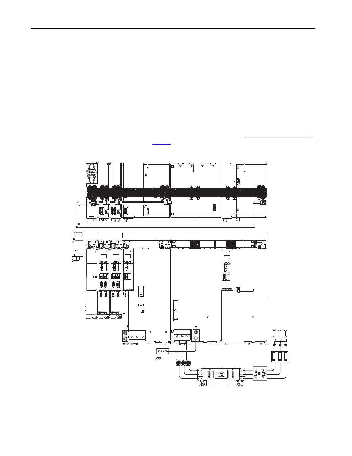
Chapter 1 Start
19
8
16
SB+/NC
NC
S1A
SCA
S2A
SBNC
NC
1606-XL
Power Supply
Input
Allen-Bradley
MOD
NET
2
1
1
I/O
6
5
10
MBRK
+
-
21mm (4 AWG-250 kcmil)
15-20 Nm (132-177 lbin)
2
W V U
MOD
NET
2
1
1
I/O
6
5
10
MOD
NET
2
1
UFB-A UFB-B
D+
D-
MF-A MF-B
D+
D-
MODULE
STATUS
MOD
DC BUS
1
I/O-A
6
510
1
I/O-B
6
510
19
8
16
SB+/NC
NC
S1A
SCA
S2A
SBNC
NC
L1 L2 L3
19
8
16
SB+/NC
NC
S1A
SCA
S2A
SBNC
NC
MOD
NET
UFB-A UFB-B
D+
D-
MF-A MF-B
D+
D-
I/O-A
6101
I/O-B
6
510
21mm (4 AWG-250 kcmil)
15-20 Nm (132-177 lbin)
2
1606-XLxxx
24V DC Control Power
(customer-supplied)
AC Input Power
Kinetix 5700 Servo Drive System
(front view)
Kinetix 5700 Servo Drive
System (top view)
Line Disconnect
Device
324…506V AC
Three-phase
Input Power
Circuit
Protection
Magnetic (M1)
Contactor
Bonded Cabinet
Ground Bus
2198-DBRxx-F
AC Line Filter
(required for CE)
Shared DC-bus Power
Shared 24V Control Power
Dual-axis Inverters
Regenerative Bus Supply
(1)
DC-bus Conditioner
Module
24V DC Control Power
Connector Plug
Single-axis Inverter
Magnetic Contactor (M1)
Control String
1321-3Rxx-x
Line Reactor
(recommended)
In this example, the 2198-RP312 regenerative bus supply is mounted on the far
right and followed by the 2198-S312-ERSx single-axis inverter, and two
2198-D020-ERSx dual-axis inverters.
• The 2198-BARCON-440DC200 DC-bus link extends the DC-bus
from the regenerative bus supply to the single-axis inverter.
• The 2198-BARCON-220DC200 DC-bus link extends the DC-bus
from the single-axis inverter to the dual-axis inverter.
• The regenerative bus supply has 24V DC wired to the connector plug
• The 2198-xxxx-P-T bus-bar connector extends 24V control power from
the input wire connector to the dual-axis and single-axis inverters.
• The DC-bus conditioner module is required when the combined motor
cable length exceeds 400 m (1312 ft). See Accessory Module Selection
on page 59
Figure 6 - Typical Shared DC-bus Installation (mounted right to left)
for more information on accessory module requirements.
24 Rockwell Automation Publication 2198-UM002G-EN-P - February 2019
(1) The regenerative bus supply can be left or right of the inverters. Further, we recommend that the highest inverter power ratings
are positioned closest to the regenerative bus supply and in decreasing order leading away from the regenerative bus supply.
Page 25
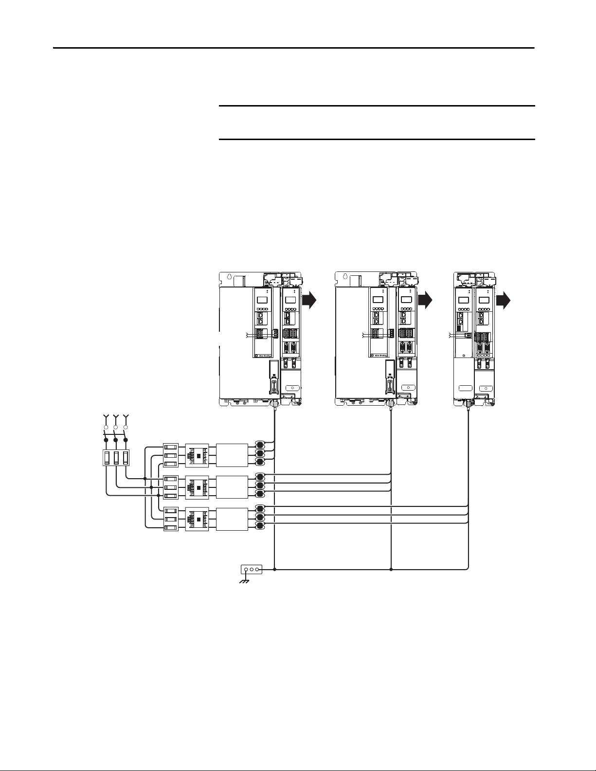
Start Chapter 1
MOD
NET
2
1
1
I/O-A
6
510
1
I/O-B
6
510
UFB-A UFB-B
D+D-D+
D-
MF-A MF-B
MOD
NET
2
1
1
I/O
6
5
10
OK+
OK–
EN–
EN+
MOD
NET
2
1
1
I/O-A
6
510
1
I/O-B
6
510
UFB-A UFB-B
D+D-D+
D-
MF-A MF-B
MOD
NET
2
1
1
I/O
6
5
10
OK+
OK–
EN–
EN+
MOD
NET
2
1
1
4
I/O
MOD
NET
2
1
UFB-A UFB-B
D+D-D+
D-
MF-A MF-B
1
I/O-A
6
510
1
I/O-B
6
510
Kinetix 5700 Servo Drive Systems
(front view)
Line Disconnect
Device
324…506V AC
Three-phase
Input Power
Circuit
Protection
Magnetic (M1)
Contac tors
Bonded Cabinet
Ground Bus
2198-DBRxx-F
AC Line Filter
(required for CE)
Dual-axis
Inverter
Regenerative Bus Supply
DC-bus
Power
Supply
Dual-axis
Inverter
Regenerative Bus Supply
Dual-axis
Inverter
Bulletin 1321
Line Reactors
Additional
Inverters
Additional
Inverters
Additional
Inverters
M1 Control
String
Magnetic Contactor (M1)
Control S tring
M1 Control
String
Circuit
Protection
2198-DBRxx-F
AC Line Filter
(required for CE)
2198-DBRxx-F
AC Line Filter
(required for CE)
In this example, three-phase input power feeds two 2198-RPxxx regenerative
power supplies and one 2198-Pxxx DC-bus power supply.
IMPORTANT We recommend that Bulletin 1321 line reactors be used in any system with
multiple regenerative bus supplies sharing the same AC input-power source.
Bulletin 1321 line reactors are used in the regenerative power supply input
power circuits to help do the following:
• Reduce circulating currents between different systems
• Prevent all power supplies on the same input power source from
nuisance thermal overload faults
Figure 7 - Input Power to Multiple Kinetix 5700 Drive Systems
Rockwell Automation Publication 2198-UM002G-EN-P - February 2019 25
Page 26
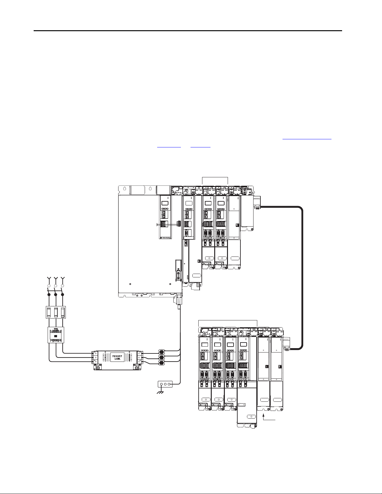
Chapter 1 Start
MOD
NET
2
1
UFB-A UFB-B
D+
D-
MF-A MF-B
MOD
NET
2
1
UFB-A UFB-B
D+
D-
MF-A MF-B
D+
D-
MOD
NET
2
1
D+
D-
MF-A MF-B
D+
D-
MOD
NET
MOD
NET
MOD
NET
2
1
2
1
2
1
UFB
UFB-A UFB-B
UFB-A UFB-B
D+D-D+
D-
D+
D-
MF-A MF-B MF-A MF-B
D+
D-
MBRK
+
-
MOD
NET
D+
D-
MF
MODULE
STATUS
MOD
NET
MODULE
STATUS
MOD
NET
2
1
UFB-A UFB-B
D+
D-
MF-A MF-B
D+
D-
MOD
NET
MODULE
STATUS
1
I/O-A
6
510
1
I/O-B
6
510
1
I/O
6
5
10
1
I/O-A
6
510
1
I/O-B
6
510
1
I/O-A
6
510
1
I/O-B
6
510
1
I/O-A
6
510
1
I/O-B
6
510
1
I/O-A
6
510
1
I/O-B
6
510
1
I/O-A
6
510
1
I/O-B
6
510
MOD
NET
2
1
1
I/O
6
5
10
OK+
OK–
EN–
EN+
Kinetix 5700 Drive System
Cluster 1 (front view)
Kinetix 5700 Extended Drive System
Cluster 2 (front view)
DC-bus Extension
Shared DC-bus and 24V DC
Control Power
Magnetic Contactor
(M1) Control String
Dual-axis Inverters
Dual-axis Inverters
Line Disconnect
Device
324…506V AC
Three-phase Input Power
Circuit
Protection
Magnetic (M1)
Contac tor
Bonded Cabinet
Ground Bus
2198-DBRxx-F
AC Line Filter
(required for CE)
Regenerative Bus Supply
2198-CAPMOD-DCBUS-IO
Extension Module
2198-CAPMOD-2240
Capacitor Module
2198-CAPMOD-2240
Capacitor Module
2198-DCBUSCOND-RP312
DC-bus Conditioner Module
Combin ed motor
cable lengths equal
300 m (984 ft).
Combined motor
cable lengths equal
480 m (1575 ft).
Single-axis
Inverter
ATTENTION: Circuit protection can
be added after the power supply
cluster to help protec t converters and
inverters from damage in the event of
a DC-bus cable short-circuit.
Bulletin 1321
Line Reactor
(recommended)
Extended Regenerative Bus Configuration Example
In this example, two drive clusters in the same cabinet are connected by the
same 458…747V DC bus voltage.
• Kinetix 5700 accessory modules provide connection points for the
DC bus at the end of cluster 1 and the beginning of cluster 2.
• The Kinetix 5700 servo drive system is capable of up to 208 A
DC-bus current. Two parallel accessory modules are needed when
the DC-bus system current exceeds 104 A.
• The DC-bus conditioner module is required when the combined
motor cable length exceeds 400 m (1312 ft). See Accessory Module
Selection on page 59 for more information on accessory module
requirements.
Figure 8 - Extended DC-bus Installation
26 Rockwell Automation Publication 2198-UM002G-EN-P - February 2019
Page 27
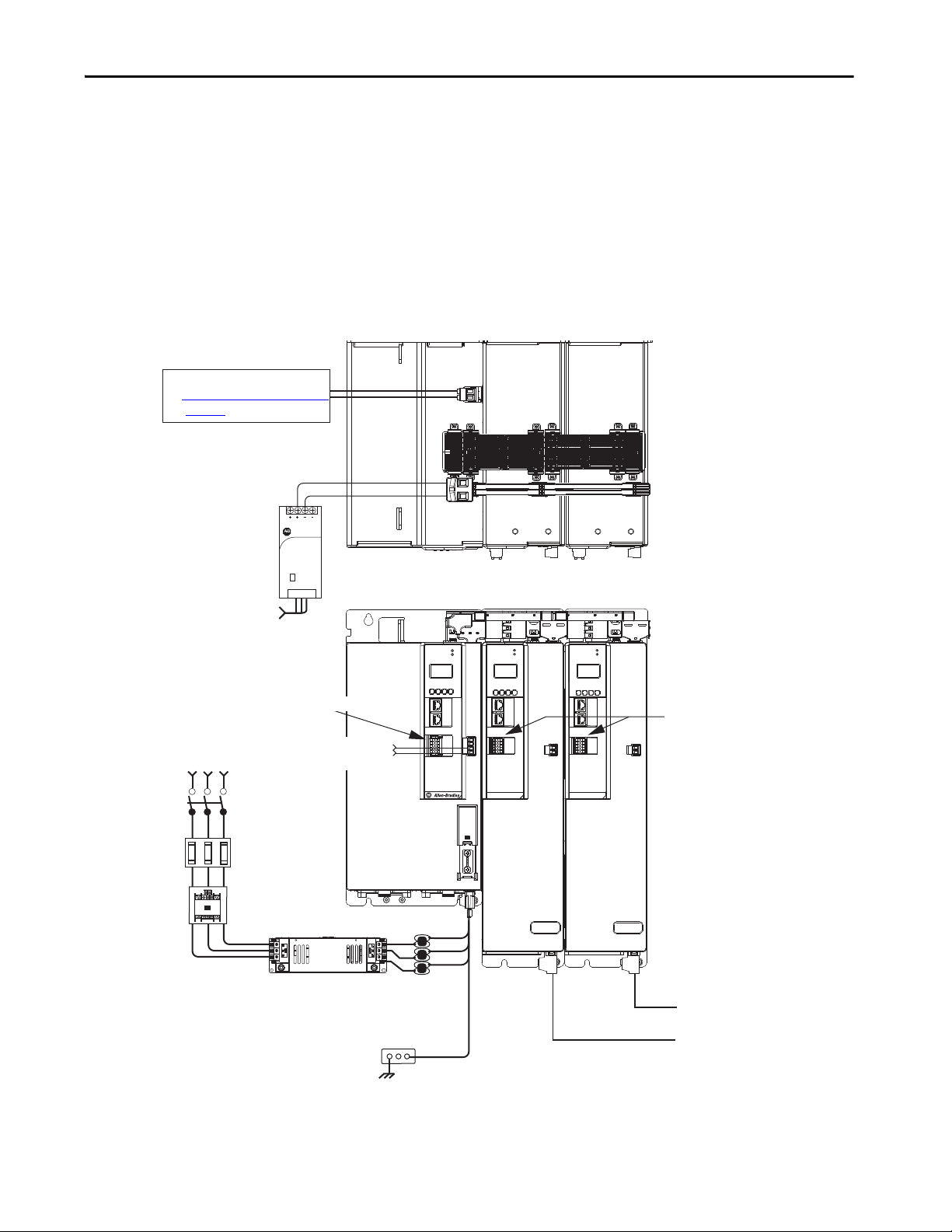
2
1
16
I/O
510
–
iPS RDY
+
MOD–
NET–
1
2
3
4
5
6
7
8
9
10
2
1
16
I/O
510
–
iPS RDY
+
MOD–
NET–
1
2
3
4
5
6
7
8
9
10
1606-XL
Power Supply
Input
Allen-Bradley
DC+
MOD
NET
2
1
1
I/O
6
5
10
OK+
OK–
EN–
EN+
DC–
Magnetic Contactor
(M1) Control String
1606-XLxxx
24V DC Control, Digital Inputs,
and iTRAK Motor Module Control Power
(customer-supplied)
AC Input Power
Kinetix 5700 iTRAK System
(front view)
Kinetix 5700 iTRAK System
(top view)
Line Disconnect
Device
324…506V AC
Three-phase
Input Power
Circuit
Protection
Magnetic (M1)
Contac tor
Bonded Cabinet
Ground Bus
Converter Digital Inputs
iTRAK Motor Modules
Regenerative Bus Supply
iTRAK
Power S upply
iTRAK
Power S upply
iTRAK Motor Modules
iTRAK Power Supply
Digital Inputs
Bulletin 2198 shared-bus
connection system for DC-bus and
24V DC control power.
Shared DC-bus Power Input
Shared 24V Control Power Input
(24V shared-bus connection system
is optional)
2198T-CHBFLS8
Motor Power
Cables
Active Shunt (optional component)
See External Active-shunt Connections
on page 183
for more information.
Bulletin 1321
Line Reactor
(recommended)
2198-DBRxx-F
AC Lin e Filter
(can be required for CE)
Start Chapter 1
iTRAK Power Supply Configuration Example
In this example, AC input power is fed to the regenerative bus supply. Two
iTRAK power supplies support up to 40 iTRAK motor modules, depending
on cable lengths and iTRAK motor-module power consumption.
Digital inputs are wired to sensors and the control circuitry at the IOD
connectors. The contactor-enable relay protects the regenerative bus supply in
the event of shutdown fault conditions.
Figure 9 - Typical iTRAK Power Supply Installation
Rockwell Automation Publication 2198-UM002G-EN-P - February 2019 27
Page 28
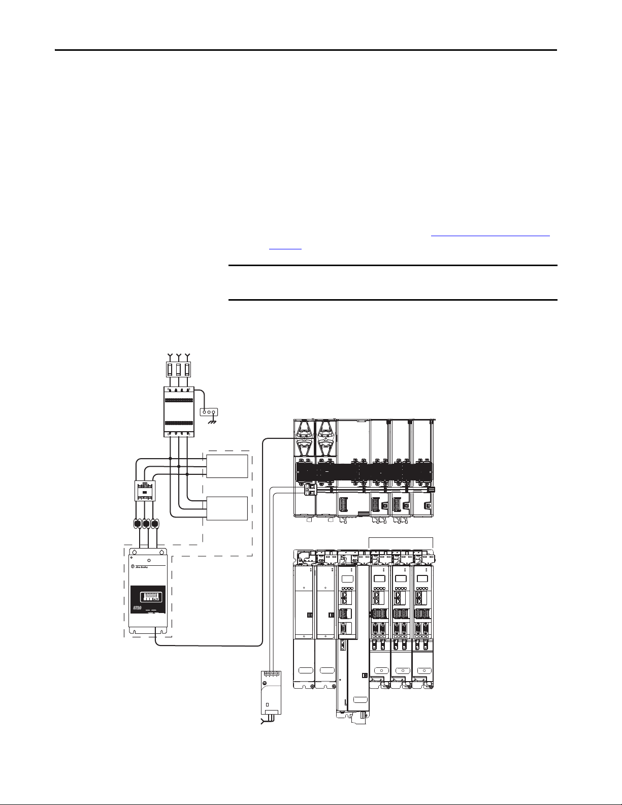
Chapter 1 Start
1606-XL
Power Supply
Input
Allen-Bradley
MOD
NET
MOD
NET
MOD
NET
2
1
2
1
2
1
UFB
UFB-A UFB-B
UFB-A UFB-B
D+D-D+
D-
D+
D-
MF-A MF-B MF-A MF-B
D+
D-
MBRK
+
-
R
E
G
E
N
E
R
A
T
IV
E
P
O
W
E
R
S
U
P
P
LY
R
E
G
E
N
E
R
A
T
IV
E
P
O
W
E
R
S
U
P
P
L
Y
87208720
MCMC
RST
PRG
ENT
READYREADY
FAULTFAULT
PROGRAMPROGRAM kWkW
V
A
MOD
NET
2
1
UFB-A UFB-B
D+
D-
MF-B
D+
D-
MOD
DC BUS
MODULE
STATUS
D+
D-
MF
19
8
16
19
8
16
19
8
16
1
I/O
6
5
10
1
I/O-A
6
510
1
I/O-B
6
510
1
I/O-A
6
510
1
I/O-B
6
510
1
I/O-A
6
510
1
I/O-B
6
510
SB+/NC
NC
S1A
SCA
S2A
SBNC
NC
SB+/NC
NC
S1A
SCA
S2A
SBNC
NC
SB+/NC
NC
S1A
SCA
S2A
SBNC
NC
MOD
DC BUS
MODULE
STATUS
1606-XLxxx
24V DC Control, Digital Inputs,
and Motor Brake Power (customer-supplied)
AC Input Power
Kinetix 5700 Servo Drive System
(front view)
Kinetix 5700 Servo Drive System
(top view)
324…506V AC
Three-phase Input Power
Circuit
Protection
Magnetic
(1)
(M1) Contactor
Bonded Cabinet
Ground Bus
8720MC-RFI80
AC Lin e Filter
(required for CE)
8720MC-LRxx
Line Reactor
8720MC-RPS065-BM-HV2
Regenerative Power Supply
Single-axis
Inverter
Dual-axis Inverters
Capacitor
Module
8720MC-HF-B2
Harmonic Filter
8720MC-VA-B
Vari sto r
Bulletin 2198 shared-bus
connection system for DC-bus and
24V DC control power.
Shared DC-bus Power Input
Shared 24V Control Power Input
(24V shared-bus connection
system is optional)
DC-bus
Conditioner
Module
8720MC-RPS Power Supply Input Power Configuration
In this example, three-phase AC input power is fed to the Bulletin 8720MC
regenerative power supply. The 8720MC-RPS DC-bus voltage supplies the
Kinetix 5700 DC-bus via the capacitor module.
• The 8720MC-RPS065 provides 65 A of DC-bus current. The 2198CAPMOD-2240 capacitor module and 2198-DCBUSCOND-RP312
DC-bus conditioner are required to reduce voltage stress on the system
components.
• If the 8720MC-RPS190 is used, the capacitor module and DC-bus
conditioner module provide up to 208 A of DC input current. DC-bus
full-regeneration is possible with this configuration.
• The DC-bus conditioner module is required when the combined motor
cable length exceeds 400 m (1312 ft). See Accessory Module Selection
on page 59
for more information on accessory module requirements.
IMPORTANT The 8720MC-RPS power supply is not compatible with the iTRAK power
supply.
Figure 10 - 8720MC-RPS Power Supply Installations
28 Rockwell Automation Publication 2198-UM002G-EN-P - February 2019
(1) This M1 contactor is controlled by the 8720MC regenerative power supply.
Page 29
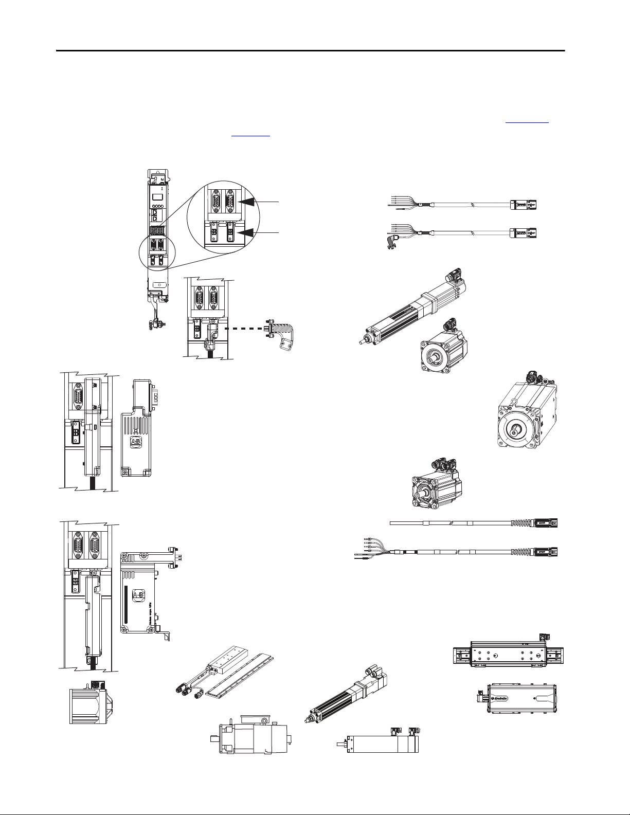
Start Chapter 1
2090-CSBM1DE Single Motor Cables
2198-KITCON-DSL Connector Kit
Accepts DSL motor feedback from VPC-Bxxxxx-Q
and (Bulletin VPL, VPF, VPS) rotary motors and
Kinetix VP electric cylinders.
Bulletin 2090 Motor Power and Feedback Cables
2198-K57CK-D15M Universal Connector Kit
Accepts multiple encoder feedback types:
• Hiperface high-resolution absolute multi-turn and single-turn encoders
– VPC-Bxxxxx-S rotary motors
– MP-Series (Bulletin MPL, MPM, MPF, MPS) rotary motors
– HPK-Series asynchronous rotary motors
– MP-Series (Bulletin MPAS, MPAR, MPAI) linear actuators
– LDAT-Series linear thrusters, LDC-Series linear motors
• Heidenhain EnDat high-resolution absolute encoders
– VPC-Bxxxxx-Y rota ry motors
– RDD-Series direct-drive motors
• Feedback-only, master feedback, or load feedback
(absolute single-turn/multi-turn Hiper face)
• Feedback-only, master feedback, or load feedback (incremental)
MP-Series Rotary Motors
(MPL-Bxxxx motor is shown)
LDAT-Series Linear Thrusters
2198-H2DCK Converter Kit
Converts 15-pin Hiperface feedback into 2-pin DSL feedback for:
• VPC-Bxxxxx-S rotary motors
• MP-Series rotary motors and linear actuators
• HPK-Se ries asynchro nous rotary motor s
• LDAT-Series linear thrusters
• Feedback-only, master feedback, or load feedback (absolute single-turn/multi-turn Hiperface)
15-pin Universal Feedback
(UFB) Connectors
2-pin Motor Feedback
(MF) Connectors
2198-Dxxx-ERSx
or 2198-Sxxx-ERSx Inverters
(2198-Dxxx-ERSx dual-axis
inverter is shown)
Kinetix VP Rotary Motors
(Bulletin VPL, VPF, VPS
and Catalog Number
VPC-Bxxxxx-Q)
HPK-Series Asynchronous Rotary Motors
and Induction Rotary Motors
(closed-loop control)
2090-CSBM1DG Single Motor Cables
RDD-Series Direct Drive
Rotary Motors
Kinetix VP Rotary Motors
Catalog Numbers
VPC-Bxxxxx-S and VPC-Bxxxxx-Y
Kinetix VP Electric Cylinders
(Bulletin VPAR)
MP-Series (Bulletin MPAS)
Integrated Linear Stages
MP-Series (Bulletin MPAI)
Heavy-duty Electric Cylinders
LDC-Series
Linear Motors
MP-Series (Bulletin MPAR)
Electric Cylinders
Motor and Auxiliary Feedback Configurations
UFB-A
D+D-D+
MF-A
UFB-A
D+D-D+
MF-A
Feedback connections are made at the 2-pin motor feedback (MF) connector
and the 15-pin universal feedback (UFB) connector. These examples illustrate
how you can use the Bulletin 2198 connector kits for making these
connections. To see motor power and brake connections, refer to Chapter 5
page 127
Figure 11 - Feedback Configuration Example
UFB-A
MOD–
NET–
2
1
I/O-B
I/O-A
16
1
6
510
510
UFB-A
UFB-B
D+D-D+
D-
MF-B
MF-A
D+D-D+
MF-A
UFB-B
D-
MF-B
UFB-B
D-
MF-B
UFB-B
D+D-D+
D-
MF-B
MF-A
UFB-A
UFB-B
D-
MF-B
on
.
m
o
c
.
b
a
.
w
A
S
w
U
w
N
I
E
D
A
M
0
0
5
X
5
X
7
X
0
X
M
X
C
X
D
X
L
X
.
X
O
.
N
O
.
T
N
A
L
C
A
I
R
E
S
A
ES
I
R
E
S
Rockwell Automation Publication 2198-UM002G-EN-P - February 2019 29
Page 30
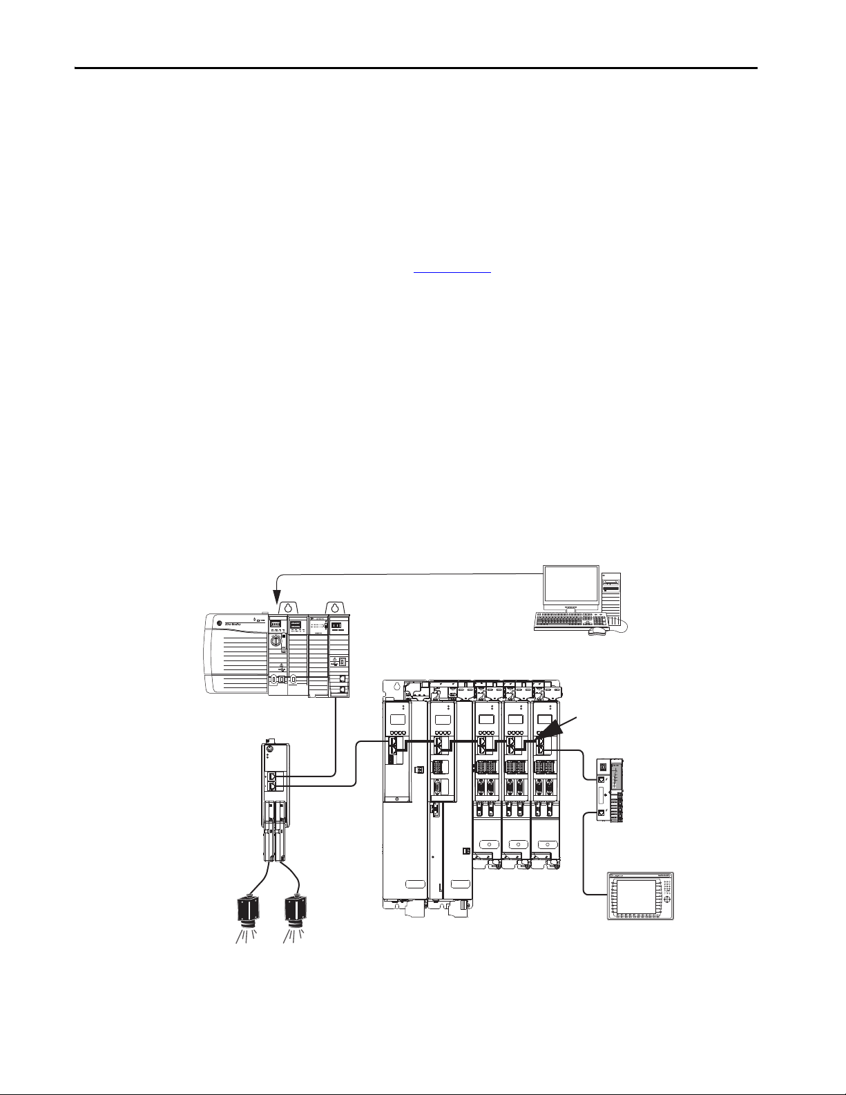
Chapter 1 Start
ControlLogix 5570 Controller
with Bulletin 1756 EtherNet/IP Module
Studio 5000 Logix Designer
Application
1585J-M8CBJM-x
Ethernet (shielded) Cable
1734-AENTR POINT I/O™
EtherNet/IP Adapter
ControlLogix Controller Programming Network
PanelView™ Plus
Display Terminal
1585J-M8CBJM-OM15
0.15 m (6 in.) Ethernet cables
for drive-to-drive connections.
Kinetix 5700 Servo Drive System
2198-ABQE
Encoder Output Module
Line Scan
Cameras
Typical Communication Configurations
The Kinetix 5700 drives support any Ethernet topology including linear, ring,
and star by using ControlLogix, GuardLogix, or CompactLogix controllers.
These examples feature the ControlLogix 5570 programmable automation
controllers with support for integrated motion and integrated safety over the
EtherNet/IP network. Other Allen-Bradley controllers are also compatible
with the Kinetix 5700 servo drives.
Refer to ControlLogix Communication Module Specifications Technical
Data, publication 1756-TD003
, for more information on ControlLogix
1756-EN2T, 1756-EN2TR, and 1756-EN3TR communication modules.
TIP These example configurations use the 2198-Pxxx DC-bus power supply.
However, 2198-RPxxx regenerative bus supply can be used instead.
Linear Topology
In this example, all devices are connected by using linear topology. The
Kinetix 5700 drive modules include dual-port connectivity, however, if any
device becomes disconnected, all devices downstream of that device lose
communication. Devices without dual ports must include the 1783-ETAP
module or be connected at the end of the line.
Figure 12 - Kinetix 5700 Linear Communication Installation
EtherNet/IP
LNK1LNK2NET OK
2
1
MOD
MOD
NET
OUTPUT-A OUTPUT-B
NET
2
1
1
4
I/O
MOD
MOD
MOD
NET
NET
MOD
NET
NET
2
1
I/O
1
6
5
10
UFB
-
MBRK
+
2
2
1
1
I/O-A
I/O-B
I/O-A
1
6
1
6
1
6
1
510
510
510
510
UFB-A UFB-B
UFB-A UFB-B
D+
D+D-D+
D+
D-
D-
D-
MF-A MF-B MF-A MF-B
2
1
I/O-B
I/O-A
I/O-B
6
1
6
1
510
D+
D-
UFB-A UFB-B
MF-A MF-B
510
D+
D-
6
1734-AENTR
02
0
POINT I O
Module
Status
Network
Activity
Network
Status
Point Bus
Status
Link 1
Activity/
System
Status
Power
Field
Power
Link 2
Activity/
Status
30 Rockwell Automation Publication 2198-UM002G-EN-P - February 2019
Page 31

Start Chapter 1
02
0
1734-AENTR
Module
Status
Network
Activity
Network
Status
Point Bus
Status
System
Power
Field
Power
POINT I O
Link 1
Activity/
Status
Link 2
Activity/
Status
MOD
NET
MOD
NET
MOD
NET
MOD
NET
2
1
1
4
I/O
2
1
2
1
2
1
UFB-A UFB-B
UFB-A UFB-B
D+D-D+
D-
D+
D-
MF-A MF-B MF-A MF-B
D+
D-
MBRK
+
-
MOD
NET
2
1
UFB-A UFB-B
D+
D-
MF-A MF-B
D+
D-
LNK1LNK2NET OK
EtherNet/IP
1
2
MOD
NET
OUTPUT-A OUTPUT-B
1
I/O
6
5
10
1
I/O-A
6
510
1
I/O-B
6
510
1
I/O-A
6
510
1
I/O-B
6
510
1
I/O-A
6
510
1
I/O-B
6
510
1734-AENTR POINT I/O
EtherNet/IP Adapter
ControlLogix Controller Programming Network
1783-ETAP
Module
1585J-M8CBJM-OM15
0.15 m (6 in.) Ethernet cable
for drive-to-drive connections.
Panel View Plus
Display Terminal
Kinetix 5700 Servo Drive System
Studio 5000 Logix Designer
Application
1585J-M8CBJM-x Ethernet
(shielded) Cable
ControlLogix 5570 Controller
with Bulletin 1756 EtherNet/IP Module
2198-ABQE
Encoder Output Module
Line Scan
Cameras
Ring Topology
In this example, the devices are connected by using ring topology. If only one
device in the ring is disconnected, the rest of the devices continue to
communicate. For ring topology to work correctly, a device level ring (DLR)
supervisor is required (for example, the Bulletin 1783 ETAP device). DLR is
an ODVA standard. For more information, refer to the EtherNet/IP
Embedded Switch Technology Application Guide, publication ENET-AP005
Devices without dual ports, for example the display terminal, require a
1783-ETAP module to complete the network ring.
Figure 13 - Kinetix 5700 Ring Communication Installation
.
Rockwell Automation Publication 2198-UM002G-EN-P - February 2019 31
Page 32

Chapter 1 Start
MOD
NET
MOD
NET
MOD
NET
MOD
NET
2
1
1
4
I/O
2
1
2
1
2
1
UFB
UFB-A UFB-B
UFB-A UFB-B
D+D-D+
D-
D+
D-
MF-A MF-B MF-A MF-B
D+
D-
MBRK
+
-
MOD
NET
2
1
UFB-A UFB-B
D+
D-
MF-A MF-B
D+
D-
LNK1LNK2NET OK
EtherNet/IP
1
2
MOD
NET
OUTPUT-A OUTPUT-B
1
I/O
6
5
10
1
I/O-A
6
510
1
I/O-B
6
510
1
I/O-A
6
510
1
I/O-B
6
510
1
I/O-A
6
510
1
I/O-B
6
510
1585J-M8CBJM-x
Ethernet (shielded) Cable
1734-AENTR POINT I/O
EtherNet/IP Adapter
ControlLogix Controller Programming Network
Panel View Plus
Display Terminal
1783-BMS
Stratix® 5700
Switch
1585J-M8CBJM-OM15
0.15 m (6 in.) Ethernet cable
for drive-to-drive connections.
Kinetix 5700 Servo Drive System
Studio 5000 Logix Designer
Application
ControlLogix 5570 Controller
with Bulletin 1756 EtherNet/IP Module
2198-ABQE
Encoder Output Module
Line Scan
Cameras
842E-CM Integrated
Motion Encoder
Star Topology
In this example, the devices are connected by using star topology. Each device is
connected directly to the switch.
Kinetix 5700 drive modules have dual ports, so linear topology is maintained
from one module to another, but the Kinetix 5700 system and other devices
operate independently. The loss of one device does not impact the operation of
other devices.
Figure 14 - Kinetix 5700 Star Communication Installation
You can use the 842E-CM integrated motion encoder for applications
requiring an external encoder for gearing or camming to the Kinetix 5700
drive. By providing auxiliary feedback directly through the EtherNet/IP
network, the 842E-CM encoder helps eliminate the need for point-to-point
wiring while letting customers use the encoder in a variety of network
topologies. For more information, see the 842E-CM Integrated Motion on
EtherNet/IP Product Profile, publication 842ECM-PP001
.
32 Rockwell Automation Publication 2198-UM002G-EN-P - February 2019
Page 33

Start Chapter 1
1585J-M8CBJM-x
Ethernet (shielded) Cable
Any Logix 5000 Controller
(ControlLogix 5570 controller is shown)
Studio 5000 Logix Designer
Application
AC Input Power
Safety
Device
Kinetix 5700 Servo Drive System
(top view)
Kinetix 5700 Servo Drive System
(front view)
Digital Inputs to Sensors and Control String
1606-XLxxx
24V DC Control, Digital Inputs,
and Motor Brake Power
(customer-supplied)
Kinetix VP
Servo Motors
Module Definition
Configured with
Motion Only
Connection
Safe Torque-off
(STO) Connectors
ControlLogix 5570 Controllers or
GuardLogix 5570 Safety Controllers
ControlLogix 5580 Controllers or
GuardLogix 5580 Safety Controllers
CompactLogix 5370 Controllers or
Compact GuardLogix 5370 Safety Controllers
CompactLogix 5380 Controllers or
Compact GuardLogix 5380 Safety Controllers
Functional Safety Configurations
EtherNet/IP
LNK1LNK2NET OK
Kinetix 5700 servo drives are capable of safe torque-off (STO) and safe stop 1
(SS1) drive-based safety functions via hardwired connections or integrated
over the EtherNet/IP network. In addition, safely limited speed (SLS) and
other controller-based safety instructions are also possible. These examples
illustrate the functional safety configuration options.
TIP These example configurations use the 2198-Pxxx DC-bus power supply.
However, 2198-RPxxx regenerative bus supply can be used instead.
Hardwired Configuration
Kinetix 5700 servo drives use the safe torque-off (STO) connector for wiring
external safety-devices and cascading hardwired safety-connections from one
drive to another.
Figure 15 - Safe Torque-off (hardwired) Configuration
SH
2
1
DC+
TM
DC INPUT
DC INPUT
Logix5585
0000
SAFETY ON
NET
LINK
OKFORCESDRUN
AC OUTPUT
19
SB+/NC
S1A
SCA
S2A
SBNC
NC
NC
16
8
Allen-Bradley
1606-XL
Power Supply
Input
MOD
NET
2
1
1
4
I/O
MOD
NET
2
1
I/O
1
6
5
10
UFB
-
MBRK
+
19
SB+/NC
S1A
SCA
S2A
SBNC
NC
NC
16
8
MOD
NET
2
1
I/O-A
I/O-B
1
6
1
6
510
510
UFB-A UFB-B
D+D-D+
D+
D-
D-
MF-A MF-B MF-A MF-B
19
8
2
1
I/O-A
1
510
UFB-A UFB-B
SB+/NC
S1A
SCA
S2A
SBNC
NC
NC
16
MOD
NET
I/O-B
6
1
6
510
D+
D-
Rockwell Automation Publication 2198-UM002G-EN-P - February 2019 33
Page 34

Chapter 1 Start
1606-XL
Power Supply
Input
Allen-Bradley
LNK1LNK2NET OK
EtherNet/IP
1
2
MOD
NET
MOD
NET
MOD
NET
MOD
NET
2
1
1
4
I/O
2
1
2
1
2
1
UFB
UFB-A UFB-B
UFB-A UFB-B
D+D-D+
D-
D+
D-
MF-A MF-B MF-A MF-B
D+
D-
MBRK
+
-
DC+
SH
SB+/NC
NC
19
8
16
19
8
16
19
8
16
S1A
SCA
S2A
SBNC
NC
SB+/NC
NC
S1A
SCA
S2A
SBNC
NC
SB+/NC
NC
S1A
SCA
S2A
SBNC
NC
1
I/O
6
5
10
1
I/O-A
6
510
1
I/O-B
6
510
1
I/O-A
6
510
1
I/O-B
6
510
1585J-M8CBJM-x
Ethernet (shielded) Cable
Compact GuardLogix 5370 Controller,
Compact GuardLogix 5380 Safety Controller or
GuardLogix 5570 Controller,
GuardLogix 5580 Safety Controller
(GuardLogix 5570 Safety Controller is shown)
Studio 5000 Logix Designer
Application
AC Input Po wer
Kinetix 5700 Servo Drive System
(top view)
Kinetix 5700 Servo Drive System
(front view)
Digital Inputs to Sensors and Control String
1606-XLxxx
24V DC Control, Digital Inputs,
and Motor Brake Power
(customer-supplied)
Kinetix VP
Servo Motors
1783-BMS
Stratix 5700
Switch
Module Definition
Configured with
Motion and Safety
Conne ction
1734-AENTR
POINT Guard I/O™
EtherNet/IP Adap ter
Safety
Device
Integrated Safety Configurations
The GuardLogix or Compact GuardLogix safety controller issues the safe
torque-off (STO) or safe stop (SS1) command over the EtherNet/IP network
and the Kinetix 5700 servo drive executes the command.
In this example, a single GuardLogix safety controller makes the Motion and
Safety connections.
IMPORTANT If only one controller is used in an application with Motion and Safety
connections, it must be a GuardLogix or Compact GuardLogix safety
controller. For more information, see the Integrated Functional Safety
Support table on page 16.
Figure 16 - Motion and Safety Configuration (single controller)
34 Rockwell Automation Publication 2198-UM002G-EN-P - February 2019
Page 35

Start Chapter 1
LNK1LNK2NET OK
EtherNet/IP
1
2
LNK1LNK2NET OK
EtherNet/IP
1
2
1606-XL
Power Supply
Input
Allen-Bradley
MOD
NET
MOD
NET
MOD
NET
MOD
NET
2
1
1
4
I/O
2
1
2
1
2
1
UFB
UFB-A UFB-B
UFB-A UFB-B
D+D-D+
D-
D+
D-
MF-A MF-B MF-A MF-B
D+
D-
MBRK
+
-
DC+
SH
SB+/NC
NC
19
8
16
19
8
16
19
8
16
S1A
SCA
S2A
SBNC
NC
SB+/NC
NC
S1A
SCA
S2A
SBNC
NC
SB+/NC
NC
S1A
SCA
S2A
SBNC
NC
1
I/O
6
5
10
1
I/O-A
6
510
1
I/O-B
6
510
1
I/O-A
6
510
1
I/O-B
6
510
1585J-M8CBJM-x
Ethernet (shielded) Cable
Compact GuardLogix 5370 Controller,
Compact GuardLogix 5380 Safety Controller or
GuardLogix 5570 Controller,
GuardLogix 5580 Safety Controller
(GuardLogix 5570 Safety Controller is shown)
Studio 5000 Logix Designer
Application
AC Input Power
Kinetix 5700 Servo Drive System
(top view)
Kinetix 5700 Servo Drive System
(front view)
Digital Inputs to Sensors and Control String
1606-XLxxx
24V DC Control, Digital Inputs,
and Motor Brake Power
(customer-supplied)
Kinetix VP
Servo Motors
1734-AENTR
POINT Guard I/O
EtherNet/IP Adapter
1783-BMS
Stratix 5700
Switch
Motion Program
Module Definition
Configured with
Motion Only
Connection
Safety Program
Module Definition
Configured with
Safety Only
Connect ion
Safety
Device
Any Logix 5000 Controller
(ControlLogix 5570 controller is shown)
In this example, a non-safety controller makes the Motion-only connection
and a separate GuardLogix safety controller makes the Safety-only connection.
IMPORTANT If two controllers are used in an application with Motion Only and Safety
Only connections, the Safety Only connection must be a GuardLogix or
Compact GuardLogix safety controller and the Motion Only connection must
be any Logix 5000 controller. For more information, see the Integrated
Functional Safety Support table on page 16.
Figure 17 - Motion and Safety Configuration (multi-controller)
Rockwell Automation Publication 2198-UM002G-EN-P - February 2019 35
Page 36

Chapter 1 Start
LNK1LNK2NET OK
EtherNet/IP
1
2
MOD
NET
2
1
1
4
I/O
MOD
NET
2
1
UFB-A UFB-B
D+D-D+
D-
MF-A MF-B
1
I/O-A
6
510
1
I/O-B
6
510
Controller-based Instruction Example
Compact GuardLogix 5380 or
GuardLogix 5580 Safety Controller
(GuardLogix 5580 Safety Controller is shown)
Kinetix 5700 Servo Drive System
with Integrated Safety Functions
Position feedba ck is se nt
separately to the drive for
safety and for motion control.
Primary Feedback
• Kinetix VP (Bulletin VPL/VPF) Servo
Motors with -W or -Q encoders
• Kinetix VP (Bulletin VPC) Servo Motors
with -Q encoders
Secondary Feedback
Bulletin 842HR SIN/COS Encoder for
Dual Feedback Monitoring
Applications
DSL feedback connector kit with primary
feedback from the motor is hidden behind the
universal feedback connector kit with
secondary feedback from the external encoder.
1585J-M8CBJM-x
Ethernet (shielded) Cable
Studio 5000 Logix Designer
Application
1734-AENTR
POINT Guard I/O
EtherNet/IP Adap ter
1783-BMS
Stratix 5700
Switch
Safety
Device
Secondary Feedback to UFB Connector
Primary Feedback to MF Connector
Safe Stop and Safe Monitor Configurations
Kinetix 5700 servo drives are capable of safe stop and safe monitor functions
via drive-based and controller-based integrated safety over the EtherNet/IP
network.
IMPORTANT For applications with safe stop and safe monitor safety functions, the
GuardLogix 5580 or Compact GuardLogix 5380 controllers must be used. For
more information, see the Integrated Functional Safety Support
page 16
.
In this example, the SS1 stopping function is used in a motion and safety
controller-based configuration with dual-feedback monitoring.
Figure 18 - Safe Motion-monitoring Configuration
table on
36 Rockwell Automation Publication 2198-UM002G-EN-P - February 2019
Page 37

Start Chapter 1
Catalog Number Explanation
Kinetix 5700 drive module catalog numbers and performance descriptions.
Table 5 - Kinetix 5700 Drive Module Catalog Numbers
Kinetix 5700 Drive
Modules
DC-bus Power Supply
Regenerative
Power Supply
Single-axis Inverters
Dual-axis Inverters
Module
Cat. No.
Width
Input Voltage
mm
2198-P031
2198-P070
2198-P141
2198-P208
55
85
324…528V AC rms,
three-phase
2198-RP088 165
2198-RP200 275 67 100
2198-RP263
2198-RP312 140 207
2198-S086-ERS3
2198-S130-ERS3
2198-S086-ERS4
2198-S130-ERS4
440
85
2198-S160-ERS3 2198-S160-ERS4 100 60.1 120.2
2198-S263-ERS3
2198-S312-ERS3
2198-D006-ERS3
2198-D012-ERS3
2198-D020-ERS3
2198-D032-ERS3
2198-S263-ERS4
2198-S312-ERS4
2198-D006-ERS4
2198-D012-ERS4
2198-D020-ERS4
2198-D032-ERS4
220
55
324…506V AC rms,
three-phase
–
–
Continuous
Output Power
kW
7
17
31
46
24 35
(1)
119 176
29.7
44.9
90
112
1.7
3.4
5.5
8.9
Continuous Output
Current to Bus
rms
A
DC
10.5
25.5
46.9
69.2
–
–
2198-D057-ERS3 2198-D057-ERS4 85 15.9 32.5
iTRAK Power Supply 2198T-W25K-ER 100 – – – 2x12.5
(1) Applies when DC-bus voltage regulation is enabled. If DC-bus voltage regulation is not enabled, the input voltage range is 324….528V AC. For more information on these two modes of operation, see
DC-bus Voltage Regulation
on page 42.
Continuous Output
Current
A 0-pk
–
–
60.8
91.9
212.1
271.5
3.5
7.0
11.3
18.3
Table 6 - Accessory Module Catalog Numbers
Accessory Modules
(1)
Cat. No.
Capacitor Module 2198-CAPMOD-2240
Extension Module 2198-CAPMOD-DCBUS-IO
DC-bus Conditioner Module 2198-DCBUSCOND-RP312
(1) Combination of any two accessory modules increases system current up to 208 A. However, modules must be mounted side-by-side and joined by two flexible bus-bars.
(2) Flexible bus-bars are included with only the 2198-CAPMOD-DCBUS-IO extension module. So, if you have two capacitor modules, two DC-bus conditioner modules, or a capacitor module and DC-bus
conditioner module mounted side by side, you must order the 2198-KITCON-CAPMOD2240 or 2198-KITCON-DCBUSCOND connector set separately.
Module
Width
System Current
(2)
Rated Voltage Capacitance
mm
55 104 A 458…747V DC, nom
2240 μF
–
Rockwell Automation Publication 2198-UM002G-EN-P - February 2019 37
Page 38

Chapter 1 Start
Table 7 - Shared-bus Connector Kit Catalog Numbers
Shared-bus Connector Kits
Cat. No.
Drive Module
Cat. No.
Application Description
2198-P031, 2198-P070, 2198-P141, 2198-P208
(1) (2)
2198-TCON-24VDCIN36
2198-CAPMOD-2240
24V DC input power to control bus 24V DC input wiring connector2198-RP088, 2198-RP200, 2198-DCBUSCOND-RP312
2198T-W25K-P-IN
(1) (2)
2198T-W25K-ER, 2198-RP263, 2198-RP312,
2198-S263-ERSx, 2198-S312-ERSx
2198-D006-ERSx, 2198-D012-ERSx
2198-H040-P-T
2198-D020-ERSx, 2198-D032-ERSx
Control power sharing Control power T-connector with bus bars, 55 mm
2198-CAPMOD-2240, 2198-DCBUSCOND-RP312
2198-H070-P-T 2198-D057-ERSx, 2198-S086-ERSx, 2198-S130-ERSx Control power sharing Control power T-connector with bus bars, 85 mm
2198-S160-P-T 2198-S160-ERSx
2198T-W25K-P-T 2198T-W25K-ER
Control power sharing Control power T-connector with bus bars, 100 mm
2198-S312-P-T 2198-S263-ERSx, 2198-S312-ERSx Control power sharing Control power T-connector with bus bars, 220 mm
(1) The input wiring connector can be inserted into any drive module (mid-stream in the drive system) to begin a new 24V control bus when the maximum current value is reached. However, the input
connector must always extend the 24V DC-bus from left to right. The 2198T-W25K-P-IN male plug is physically larger than the male plug on 2198-TCON-24VDCIN36.
(2) For drive module amp ratings and connector wire size information, see Control Power
on page 113, and CP Connector Plug Wiring Specifications table on page 146, respectively.
38 Rockwell Automation Publication 2198-UM002G-EN-P - February 2019
Page 39

Start Chapter 1
Agency Compliance
If this product is installed within the European Union and has the CE mark,
the following regulations apply.
ATT EN TI ON : Meeting CE requires a grounded system, and the method of
grounding the AC line filter and drive module must match. Failure to do this
renders the filter ineffective and can cause damage to the filter. For
grounding examples, refer to Grounded Power Configurations
on page 129.
For more information on electrical noise reduction, refer to the System Design
for Control of Electrical Noise Reference Manual, publication GMC-RM001
To meet CE requirements, these requirements apply:
• Install an AC line filter (catalog number 2198-DBRxx-F) for input
power as close to the 2198-Pxxx DC-bus power supply or 2198-RPxxx
regenerative bus supply as possible.
• Bond DC-bus power supplies, regenerative bus supplies, inverter
modules, capacitor modules, and line filter grounding screws by using a
braided ground strap as shown in Figure 91 on page 139
.
• When using the 2198-P070 DC-bus power supply above 45 °C (113 °F)
with stranded input power wiring, conductors must be single-core
2
6mm
stranded copper with 90 °C minimum rating.
• When using the 2198-RP088 regenerative power supply above 40 °C
(104 °F) with stranded input power wiring, conductors must be singlecore 6 mm
2
stranded copper with 90 °C minimum rating.
• Use Bulletin 2090 single motor cables with Kinetix VP servo motors.
Use Bulletin 2090 motor power/brake and feedback cables for other
compatible Allen-Bradley motors and actuators. Motor cable shieldclamp on the drive must be used.
• Combined motor power cable length for all axes on the same DC bus
must not exceed:
– 1200 m (3937 ft) for 2198-Pxxx DC-bus power supplies and
2198-RPxxx regenerative bus supplies when paired with
2198-DBRxx-F line filters.
– 400 m (1312 ft) for 2198-Pxxx DC-bus power supplies when paired
with 2198-DBxx-F line filters.
Drive-to-motor feedback cables must not exceed 90 m (295 ft),
depending on system components.
• Motor cable length for the iTRAK power supply to iTRAK motor
modules must be at least 3 m (9.8 ft), not to exceed 30 m (98.4 ft).
• Use Bulletin 2198T power cables with iTRAK systems.
• Install the Kinetix 5700 system inside an approved enclosure. Run input
power wiring in conduit (grounded to the enclosure) outside of the
enclosure. Separate signal and power cables.
• Segregate input power wiring from control wiring and motor cables.
.
Refer to Appendix A on page 341
for input power wiring and drive/motor
interconnect diagrams.
Rockwell Automation Publication 2198-UM002G-EN-P - February 2019 39
Page 40

Chapter 1 Start
Notes:
40 Rockwell Automation Publication 2198-UM002G-EN-P - February 2019
Page 41

Chapter 2
Plan the Kinetix 5700 Drive System Installation
This chapter describes system installation guidelines used in preparation for
mounting your Kinetix® 5700 drive system components.
Top ic Pa ge
System Design Guidelines 41
Accessory Module Selection 59
Electrical Noise Reduction 67
ATT EN TI ON : Plan the installation of your system so that you can perform all
cutting, drilling, tapping, and welding with the system removed from the
enclosure. Because the system is of the open type construction, be careful to
keep metal debris from falling into it. Metal debris or other foreign matter
can become lodged in the circuitry and result in damage to the components.
System Design Guidelines
Use the information in this section when planning to mount your system
components on the panel.
For on-line product selection and system configuration tools, including
AutoCAD (DXF) drawings of the product, refer to
https://www.rockwellautomation.com/global/support/selection.page
.
System Mounting Requirements
• To comply with UL and CE requirements, the Kinetix 5700 drive
system must be mounted in a grounded conductive enclosure offering
protection as defined in standard IEC 60529 to IP20 such that they are
not accessible to an operator or unskilled person.
To maintain the functional safety rating of the Kinetix 5700 drive
system, this enclosure must be appropriate for the environmental
conditions of the industrial location and provide a protection class of
IP54 or higher.
• The panel you install inside the enclosure for mounting your system
components must be on a flat, rigid, vertical surface that won’t be
subjected to shock, vibration, moisture, oil mist, dust, or corrosive
vapors in accordance with pollution degree 2 (EN 61800-5-1) because
the product is rated to protection class IP20 (EN 60529).
Rockwell Automation Publication 2198-UM002G-EN-P - February 2019 41
Page 42

Chapter 2 Plan the Kinetix 5700 Drive System Installation
• Size the system enclosure so as not to exceed the maximum ambient
temperature rating. Consider heat dissipation specifications for all
system components.
• Use high-frequency (HF) bonding techniques to connect the modules,
enclosure, machine frame, and motor housing, and to provide a lowimpedance return path for high-frequency (HF) energy and reduce
electrical noise.
Bond the Kinetix 5700 system power supply, inverter modules, iTRAK®
power supply, accessory modules, and line filter grounding screws by
using a braided ground strap as shown in Figure 91 on page 139
Refer to the System Design for Control of Electrical Noise Reference Manual,
publication GMC-RM001
reduction.
, to better understand the concept of electrical noise
.
DC-bus Voltage Regulation
The 2198-Pxxx DC-bus power supply does not regulate DC-bus voltage. As a
result, the DC-bus power supply always has DC-bus voltage regulation
disabled. The 2198-RPxxx regenerative bus supply can be configured to
provide active DC-bus voltage regulation or passive AC rectification like the
2198-Pxxx DC-bus (converter) power supply.
IMPORTANT Active or passive DC-bus voltage regulation must be determined during
system configuration in the Studio 5000 Logix Designer® application.
IMPORTANT Regeneration back to the AC source is only possible when the DC-bus voltage
regulation is enabled.
Converter Startup Method
The Converter Startup Method (Axis Properties>General category) specifies
the method to be used to initiate transition of the regenerative converter axis
from the STOPPED state to the STARTING state.
ATT EN TI ON : To help prevent permanent inverter damage, make sure that all
inverter ground jumpers are removed before enabling DC-bus voltage
regulation.
Set the Converter Startup Method to one of these two settings:
• Automatic (default): After applying AC, the converter automatically
transitions to the RUNNING state with active DC-bus voltage
regulation loops operational
• Enable Request: After applying AC, the converter stays in the
STOPPED state and performs passive AC rectification. Once it receives
an Enable Request from the controller, the converter transitions to the
RUNNING state with active DC-bus voltage control loops operational
42 Rockwell Automation Publication 2198-UM002G-EN-P - February 2019
Page 43

Plan the Kinetix 5700 Drive System Installation Chapter 2
>
2
• 1.05
Bus Voltage Set Point (V )
DC
AC Input Voltage (V ) •
RMS
–
2
Boost Voltage = Bus Voltage Set Point (V )
DC
AC Input Voltage (V ) •
RMS
In Enable Request mode, you must issue an MSO instruction (after AC is
applied and CIP_Axis_State = STOPPED) to enable voltage regulation on the
regenerative bus supply and an MSF instruction to disable voltage regulation.
Bus Voltage Loop Parameters
The regenerative bus supply uses an active control loop to maintain the DC bus
voltage at a specified level (or reference) and has two settings for the Bus
Voltage Reference Source (Axis Properties>Bus Voltage Loop category>
Parameters):
• Automatic (default) setting: The converter optimizes the
BusVoltageReference for the best converter performance
• Manual setting: You configure the desired BusVoltageSetPoint value for
the BusVoltageReference signal
In Manual mode, the BusVoltageSetPoint must be greater than 5% of the peak
input AC voltage (or it is clamped automatically) with a maximum of
747V DC.
Boost voltage is the difference between the rectified AC voltage and the
BusVoltageSetPoint.
IMPORTANT Setting a manual fixed DC-bus voltage sets peak motor output power
performance regardless of the variance of the input AC rms. Higher boost
voltage increases Total Harmonic Distortion (THD), reduces efficiency, and
increases acoustic noise, but this is normal and expected. For example,
optimal operation is best achieved for 460V AC motors when the input AC
rms is also at 460V AC nominal, Automatic mode is selected, and the DC-bus
voltage regulates at approximately 683V DC.
Refer to Configure Regenerative Bus Supply Axis Properties
on page 224 for
more information.
Rockwell Automation Publication 2198-UM002G-EN-P - February 2019 43
Page 44

Chapter 2 Plan the Kinetix 5700 Drive System Installation
AC Line Filter Selection
An AC line filter is required to meet CE requirements. Install an AC line filter
for input power as close to the 2198-Pxxx DC-bus power supply or
2198-RPxxx regenerative bus supply as possible.
IMPORTANT AC line filters are only recommended with grounded WYE power
configurations. For facility power configuration examples, see Input Power
Configurations for Kinetix 5700 Power Supplies on page 129.
Table 8 - AC Line Filter Selection
DC-bus Power Supply
Cat. No.
2198-P031
2198-P070
2198-P141
2198-P208
2198-P208 (2 in parallel)
2198-P208 (3 in parallel)
(1) The use of 2198-DBRxx-F line filters provide a maximum motor-power cable length of up to 1200 m (3937 ft). Maximum motor-power cable length with 2198-DBxx-F line filters is 400 m (1312 ft).
(2) See Chapter 5
Specifications Technical Data, publication KNX-TD003
(3) When using 2198-DBRxx-F line filters with DC-bus power supplies, remove all inverter ground jumpers to reduce overall system leakage-inductance current.
(4) When using 2198-DBRxx-F line filters with regenerative bus supplies, remove all inverter ground jumpers to prevent permanent damage to the inverters.
beginning on page 127, for more information on maximum cable lengths and how the use of 2198-DBRxx-F line filters affe ct ground screw/jumper settings. See Kinetix Servo Drive
AC Line Filter
Cat. No.
• 2198-DBR20-F or
• 2198-DB20-F
• 2198-DBR40-F or
• 2198-DB42-F
• 2198-DBR90-F or
• 2198-DB80-F
• 2198-DBR200-F or
• 2198-DB290-F
(1) (2) (3)
, for AC line filter specifications.
Regenerative Bus Supply
Cat. No.
2198-RP088 2198-DBR40-F
2198-RP200 2198-DBR90-F
2198-RP263
2198-RP312
AC Line Filter
Cat. No.
2198-DBR200-F
(1) (2) (4)
IMPORTANT Use 2198-DBxx-F line filters only as field replacements in existing installations that use DC-bus power supplies and have
inverter ground jumpers installed. Select 2198-DBRxx-F line filters for all new systems and remove inverter ground jumpers.
2198-DBRxx-F line filters can also be used to replace existing 2198-DBxx-F line filters, but you must remove the inverter ground
jumpers.
44 Rockwell Automation Publication 2198-UM002G-EN-P - February 2019
Page 45

Plan the Kinetix 5700 Drive System Installation Chapter 2
AC Line Impedance Considerations
DC-bus power supplies do not require an isolation transformer for three-phase
input power. Regenerative bus supplies also do not require an isolation
transformer for three-phase input power unless they are connected to cornergrounded or ungrounded facility power. See Input Power Configurations for
Kinetix 5700 Power Supplies on page 129 for example configurations.
IMPORTANT These recommendations are advisory and do not address all situations.
Site-specific conditions must be considered for proper installation.
A transformer can be required to match the voltage requirements of the power
supply to the available service. For the AC input voltage requirements, refer to
the Kinetix 5700 power specifications in the Kinetix Servo Drives Technical
Data, publication KNX-TD003
IMPORTANT When using an autotransformer, make sure that the phase to neutral/
ground voltage does not exceed the input voltage ratings of the power
supply.
.
Use a safety factor of 1.5 for three-phase power (where safety factor is used to
compensate for transformer, drive modules, motor losses, and to account for
utilization in the intermittent operating area of the torque speed curve).
EXAMPLE Sizing a transformer to the voltage requirements of this power supply:
2198-P141: 31kW x 1.5 = 46.5 kVA transformer.
In the following use cases, an additional transformer or line reactor is required
due to faults or potential damage associated with AC line disturbances:
• Installation site has switched power-factor correction capacitors.
• Installation site has lightning strikes or voltage spikes in excess of 6000V
peak.
• Installation site has power interruptions or voltage dips in excess of
200VAC.
• The transformer kVA is more than 10 times larger than the drive kVA, or
the percent source impedance relative to each converter is less than 0.5%.
In the following use cases, a line reactor is required due to faults associated with
sharing AC line-input on multiple converters:
• Repetitive AC input line-voltage notching is present. For example, if
silicon controlled rectifier drive is connected to the same AC inputpower source.
– In drive systems that include the regenerative bus supply, repetitive
AC line voltage notching can cause the integrated AC line filter to
overheat and result in FLT S18 converter overtemperature fault.
Rockwell Automation Publication 2198-UM002G-EN-P - February 2019 45
Page 46

Chapter 2 Plan the Kinetix 5700 Drive System Installation
% impedance is the nameplate impedance of the transformer.
Z
xfmr
=
(V
line-line
)
2
VA
* % Impedance
Or
% impedance is the nameplate impedance of the transformer.
• Powering multiple (two or more) regenerative bus supplies from the
same AC input-power source.
– Switching ripple from each regenerative bus supply can interfere with
other regenerative bus supplies on the same AC input power source.
• Powering 2198-Pxxx DC-bus power supply and 2198-RPxxx
regenerative bus supply from the same AC input-power source.
– Switching ripple from the regenerative bus supply can impact the
temperature of DC-bus capacitors in the DC-bus power supply. In
this use case, a line reactor is required in the AC input-power string
leading to the regenerative bus supply.
– Line reactor in the AC input-power string is not required for the
DC-bus power supply in this use case, but is recommended for the
prevention of issues caused by other use cases.
• Powering two or three 2198-P208 DC-bus power supplies from the
same AC input-power source that share the same DC-bus.
– In this use case, a line reactor is required for each 2198-P208 DC-bus
power supply to make sure that they share current more evenly.
Use these equations to calculate the impedance of the DC-bus power supply,
regenerative bus supply, or transformer to check the percent source-impedance
relative to the power supply to make sure it is not less than 0.5%. An additional
transformer or line reactor is required in this use case.
DC-bus Power Supply or Regenerative Bus Supply Impedance (in ohms)
V
Z
=
drive
3 * I
line-line
input-rating
Transformer Impedance (in ohms)
V
line-line
Z
=
xfmr
3 * I
* % Impedance
xfmr-rated
Transformer Impedance (in ohms)
V
line-line
Z
=
xfmr
3 * I
* % Impedance
xfmr-rated
46 Rockwell Automation Publication 2198-UM002G-EN-P - February 2019
Page 47

Plan the Kinetix 5700 Drive System Installation Chapter 2
Z
xfmr
Z
drive
0.2304
102.6
= 0.00224 = 0.22%=
EXAMPLE The DC-bus power supply or regenerative bus supply is rated 1 Hp, 480V,
2.7 A input.
The supply transformer is rated 50,000VA (50 kVA), 5% impedance.
V
Z
=
drive
3 * I
line-line
input-rating
480V
= = 102.6 Ohms
3 * 2.7
Kinetix 5700
Power Supply
DC-bus Power Supply
Regenerative Bus Supply
2
)
(V
line-line
=
Z
xfmr
* % Impedance =
VA
2
480
* 0.05 = 0.2304 Ohms
50,000
The percent (%) impedance has to be in per unit (5% becomes 0.05) for the
formula.
0.22% is less than 0.5%. Therefore, this transformer is too large for the
DC-bus power supply or regenerative bus supply. Consider adding either a
line reactor or isolation transformer.
Bulletin 1321 Line Reactor Selection
Power Supply
Cat. No.
2198-P031 1 1321-3R12-B Recommended
2198-P070 1 1321-3R35-B Recommended
2198-P141 1 1321-3R55-B Recommended
2198-P208
2198-RP088 1 1321-3R35-A Recommended
2198-RP200 1 1321-3R100-A Recommended
2198-RP263 1 1321-3R160-B Recommended
2198-RP312 1 1321-3R200-A Recommended
Number of Power Supplies
in a Bus Group
1
2Required
3Required
Bulletin 1321 Line Reactor
Cat. No.
1321-3R80-B
Status
Recommended
See Power Wiring Examples on page 343 for AC input-power interconnect
diagrams. For Bulletin 1321 line reactor specifications, see the 1321 Power
Conditioning Products Technical Data, publication 1321-TD001
.
IMPORTANT You can group multiple 2198-Pxxx DC-bus power supplies on one line
reactor if they do not share same DC bus. However, the line reactor percent
impedance must be large enough when evaluated for each DC-bus power
supply separately, not evaluated for all loads connected at once.
Rockwell Automation Publication 2198-UM002G-EN-P - February 2019 47
Page 48

Chapter 2 Plan the Kinetix 5700 Drive System Installation
Circuit Breaker/Fuse Selection
The Kinetix 5700 power supplies use internal solid-state motor short-circuit
protection and, when protected by suitable branch circuit protection, are rated
for use on a circuit capable of delivering up to 200,000 A (fuses) and 65,000 A
(circuit breakers).
Refer to Power Wiring Examples
, on page 343, for the wiring diagram.
ATT EN TI ON : Do not use circuit protection devices on the output of an AC
drive as an isolating disconnect switch or motor overload device. These
devices are designed to operate on sine wave voltage and the drive’s PWM
waveform does not allow it to operate properly. As a result, damage to the
device occurs.
Table 9 - DC-bus Power Supply UL/CSA Circuit-protection Specifications
DC-bus Power Supply
Cat. No.
2198-P031
2198-P070 LPJ-40SP (40A) N/A 140M-F8E-C45 140G-G6C3-C50
2198-P141 LPJ-70SP (70A) N/A N/A 140G-G6C3-C90
2198-P208 LPJ-100SP (100A) N/A N/A 140G-G6C3-D12
(1) For applications requiring CSA certification, fuses (Bussmann catalog number 170M1760) must be added to the DC link between the two drive clusters when circuit breakers are used for branch circuit
protection. The DC bus fuses are not required when AC line fuses are used for branch circuit protection.
(2) These Bulletin 140M circuit breakers, when used as self-protected (Type E) devices, and Bulletin 1489 circuit breakers can be used on only WYE power systems (480Y/277V).
Input Voltage
(three-phase) nom
324…528V AC
Bussmann Fuses
Cat. No.
LPJ-15SP (15A) 1489-M3D250 140M-D8E-C25 140G-G6C3-C25
(1)
Miniature CB
Cat. No.
(2)
Motor Protection CB,
Self Protected CMC
Cat. No.
Table 10 - Regenerative Bus Supply UL/CSA Circuit-protection Specifications
Regenerative Bus Supply
Cat. No.
2198-RP088
2198-RP200 LPJ-125SP (125A) AJT125 (125A) – 140G-J6F3-D15
2198-RP263 LPJ-200SP (200A) AJT200 (200A) – 140G-K6F3-D30
2198-RP312 LPJ-250SP (250A) AJT250 (250A) – 140G-K6F3-D40
(1) Applies when DC-bus voltage regulation is enabled. If DC-bus voltage regulation is not enabled, then the input voltage range is 324….528V AC. For more information on these two modes of
operation, see DC-bus Voltage Regulation
(2) For applications requiring CSA certification, fuses (Bussmann catalog number 170M1760) must be added to the DC link between the two drive clusters when circuit breakers are used for branch circuit
protection. The DC bus fuses are not required when AC line fuses are used for branch circuit protection.
Input Voltage
(three-phase) nom
324…506V AC rms
(1)
on page 42.
Bussmann Fuses
Cat. No.
LPJ-45SP (45A) AJT45 (45A) – 140G-G6C3-C60
(2)
Mersen Fuses
Cat. No.
Miniature CB
Cat. No.
(2)
Molded Case CB
Cat. No.
Molded Case CB
Cat. No.
Table 11 - DC-bus Power Supply IEC (non-UL/CSA) Circuit-protection Specifications
DC-bus Power Supply
Cat. No.
2198-P031
2198-P070 40 N/A 1492-SPM3D400 140M-F8E-C45 140G-G6C3-C50
2198-P141 75 N/A 1492-SPM3D630 140MG-H8E-C60 140G-G6C3-C90
2198-P208 110 N/A N/A 140MG-H8E-D10 140G-G6C3-D12
48 Rockwell Automation Publication 2198-UM002G-EN-P - February 2019
Drive Voltage
(three-phase) nom
324…528V AC
DIN gG Fuses
Amps, max
16 1489-M3D250 N/A 140M-D8E-C25 140G-G6C3-C25
Miniature CB
Cat. No.
Motor Protection CB
Cat. No.
Molded Case CB
Cat. No.
Page 49

Plan the Kinetix 5700 Drive System Installation Chapter 2
Table 12 - Regenerative Bus Supply IEC (non-UL/CSA) Circuit-protection Specifications
Regenerative Bus Supply
Cat. No.
2198-RP088
2198-RP200 125 – – 140MG-J8E-D15 140G-J6F3-D15
2198-RP263 200 – – – 140G-K6F3-D30
2198-RP312 250 – – – 140G-K6F3-D40
(1) Applies when DC-bus voltage regulation is enabled. If DC-bus voltage regulation is not enabled, then the input voltage range is 324….528V AC. For more information on these two modes of
operation, see DC-bus Voltage Regulation
Input Voltage
(three-phase) nom
324…506V AC rms
(1)
on page 42.
DIN gG Fuses
Amps, max
50 1489-M3C600 1492-SPM3C630 140MG-H8E-C60 140G-G6C3-C60
Miniature CB
Cat. No.
Motor Protection CB
Cat. No.
Molded Case CB
Cat. No.
Refer to the Kinetix Servo Drives Technical Data, publication KNX-TD003,
for additional power specifications for your 2198-Pxxx DC-bus power supply
and 2198-RPxxx regenerative bus supply.
24V Control Power Evaluation
The Kinetix 5700 drive system requires 24V DC input for its control circuitry.
Due to the 24V shared-bus connection system and the 24V current
requirements of the Kinetix 5700 drives, a thorough evaluation of control
power is required prior to implementation. Consider the following when sizing
such a system:
• Verify that the 24V DC power supply is capable of supplying the 24V
current requirements of your Kinetix 5700 drive system. See Calculate
24V DC Control Power Current Demand on page 396 to determine the
24V current requirements. For systems with a high 24V current demand,
consider the following:
– Install separate 24V power supplies for each cluster or change the
cluster configuration to more evenly divide the 24V current demand.
– Install separate 24V power supplies for each Bulletin 2198 power
supply and inverter.
• Verify that the wiring being used is capable of supplying the
Kinetix 5700 drive system with a voltage within the 24V input-voltage
range; 24V ±10% (21.6…26.4V DC). Consider the following:
– Mount the 24V power supply as close to the Kinetix 5700 drive
system as possible to minimize input voltage drop.
2
– Install larger gauge wire, up to 4 mm
AWG) for 24V control power when using the CP connectors
included with the module; or use the 24V shared-bus connection
system to lower the DC wire resistance with up to 10 mm
and result in a lower voltage drop.
(12 AWG) and 6 mm2 (10
2
(6 AWG)
IMPORTANT The 24V current demand, wire gauge, and wire length all impact the voltage
drop across the wiring being used. For an example, see 24V DC Voltage Drop
Calculation Example on page 397.
Rockwell Automation Publication 2198-UM002G-EN-P - February 2019 49
Page 50

Chapter 2 Plan the Kinetix 5700 Drive System Installation
Contactor Selection
The AC three-phase contactor control string must be wired in series with the
contactor-enable relay at the CED connector. The contactor-enable relay
(applies to 2198-Pxxx DC-bus power supply and 2198-RPxxx regenerative bus
supply) is rated at 24V DC (28V, max) and 1.0 A, max.
IMPORTANT Applying more than 28V DC control voltage or more than 1.0 A control
current to the contactor can cause permanent damage to the DC-bus power
supply or regenerative bus supply.
ATT EN TI ON : Wiring the contactor-enable relay is required. To avoid personal
injury or damage to the system, wire the contactor-enable relay into your
control string so that:
• three-phase power is removed and the power supply is protected under
various fault conditions.
• three-phase power is never applied to the Kinetix 5700 drive system before
control power is applied.
Contactor with auxiliary contacts is strongly recommended when used with
2198-RPxxx regenerative bus supply. Wire auxiliary contact to digital input #2
(default setting) to monitor the three-phase input power. See Contactor
Wiring Examples on page 358 for wiring examples.
Table 13 - DC-bus Power Supply Contactor Specifications
DC-bus Power Supply
Cat. No.
2198-P031 100-C16EJ10
2198-P070 100-C37EJ10
2198-P141 100-C72DJ10
2198-P208 100-C97DJ10
2198-P208 (2 in parallel) 100-E190KJ11
2198-P208 (3 in parallel) 100-E305KJ11
(1) Auxiliary contact configuration 10 indicates there is 1 N.O. and 0 N.C. contacts. Other configurations are available.
(2) For contactors that are not Bulletin 100-E type, the integrated diode is required with the contactor coil. See Knowledgebase document 19362
(3) These DC-bus power supplies require an additional intermediate relay used with the contacto r.
Contactor
Cat. No.
Table 14 - Regenerative Bus Supply Contactor Specifications
Regenerative Bus Supply
Cat. No.
2198-RP088 100-C43EJ10
2198-RP200 100-E116KJ11
2198-RP263 100-E205KJ11
2198-RP312 100-E265KJ11
(1) Auxiliary contact configuration 10 indicates there is 1 N.O. and 0 N.C. contacts. 11 indicates there is 1 N.O. and 1 N.C. contact. Other config urations are available.
(2) These contactor catalog numbers include a 24V DC coil. For contactors that are not Bulletin 100-E type, see Knowledgebase document 19362
Contactor
Cat. No.
(1) (2)
(1) (2)
Intermediate Relay
Cat. No.
N/A
700-HB32Z24 (relay)
700-HN153 (socket)
for more information.
Intermediate Relay
Cat. No.
N/A
for more information.
(3)
50 Rockwell Automation Publication 2198-UM002G-EN-P - February 2019
Page 51

Plan the Kinetix 5700 Drive System Installation Chapter 2
2198-R014, 2198-R031,
and 2198-R127
Shunt Modules
2198-R004
Shunt Resistor
Passive Shunt Considerations
The 2198-Pxxx DC-bus power supplies all include an internal shunt that is
wired to the shunt resistor (RC) connector at the factory. Bulletin 2198-Rxxx
external passive shunts are available to provide additional shunt capacity for
applications where the internal shunt capacity is exceeded.
IMPORTANT Keep the DC-bus power supply internal shunt wires connected unless you
have an external passive shunt to connect.
IMPORTANT 2198-RPxxx regenerative bus supplies do not support passive shunts. The
active shunt (RC) connector is used for making active shunt connections.
Table 15 - DC-bus Power Supply Passive-shunt Options
DC-bus Power Supply
Cat. No.
2198-P031
2198-P070 – – X X
2198-P141
2198-P208 XXXX
(1) Shunt resistor selection is based on the needs of your actual hardware configuration.
Internal Shunt Specifications
ΩW2198-R127 2198-R031 2198-R014 2198-R004
37.5 75
13.5 200
External Shunt Module Compatibility
Cat. No.
––XX
XXXX
(1)
Catalog numbers 2198-R014, 2198-R031, and 2198-R127 are composed of
resistor coils that are housed inside an enclosure. Catalog number 2198-R004
is a shunt resistor without an enclosure.
Figure 19 - External Passive Shunts
External Shunt Module Specifications
Shunt Module
Cat. No.
2198-R004 33 400 1.8 (4.0)
2198-R014 9.4 1400 9.1 (20)
2198-R031 33 3100 16.8 (37)
2198-R127
(1) This product presents a lift hazard. To avoid personal injury, use care when lifting the product.
(1)
Resistance
Ω
13 12,700 22.2 (49)
Continuous Power
W
Weight, a pprox
kg (lb)
How the Bulletin 2198-Rxxx shunts connect to the 2198-Pxxx DC-bus power
supply is explained in External Passive-shunt Connections
illustrated with interconnect diagrams in Passive Shunt Wiring Examples
page 359
Rockwell Automation Publication 2198-UM002G-EN-P - February 2019 51
.
on page 182 and
on
Page 52

Chapter 2 Plan the Kinetix 5700 Drive System Installation
Active Shunt Considerations
External active shunts are required in the following use cases:
• The 2198-RPxxx regenerative bus supply provides DC-bus power while
DC-bus regulation is not enabled.
• One permanent magnet motor runs above its bus overvoltage speed. See
Field Weakening Mode
• One permanent magnet motor drives a vertical load that could make the
motor accelerate above the bus overvoltage speed during a fault
condition.
• Any condition where total shared DC-bus regenerative power is greater
than the 2198-RPxxx regenerative bus supply capacity. For example,
consider a peak-power stopping condition.
• The 2198-RPxxx regenerative bus supply is operating with DC-bus
regulation enabled and the regenerative bus supply loses three-phase AC
input power, 24V DC input power, or has a fault condition.
ATT EN TI ON : To avoid damage to the Kinetix 5700 drive system, wire the
active shunt thermal switch to a digital input on the power supply and
configure the Shunt Thermal Switch OK function in the Logix Designer
application.
on page 446 for a description of this feature.
ATT EN TI ON : DC-bus failure can cause damage to all drive modules in the
bus group, not just the inverter connected to the motor.
Active shunts are available from the Rockwell Automation Encompass™ partner
Powerohm Resistors, Inc. See http://www.powerohm.com
for more
information on Powerohm active shunts.
IMPORTANT Powerohm Bulletin PKBxxx active shunt modules use built-in internal brake
resistors. Bulletin PWBxxx active shunt modules require appropriately sized
external brake resistors.
Table 16 - Compatible Active Shunt Specifications (internal brake resistor)
Kinetix 5700 Power Supply
2198-Pxxx DC-bus power supply or
2198-RPxxx regenerative bus supply
when DC-bus regulation is not enabled.
2198-RPxxx regenerative bus supply
when DC-bus regulation is enabled.
(1) How the Powerohm PKBxxx shunts connect to the 2198-Pxxx DC-bus power supply and 2198-RPxxx regenerative bus supply is explained in External Active-shunt Connections on page 183 and
illustrated with interconnect diagrams in Active Shunt Wiring Examples
Powerohm
Resistors
Cat. No.
PKB005
PKB010 2.06 52.7 – 2.75 14.2
PKB050 7.00 10.5 – 9.30 71.4
PKB005-800
PKB010-800 2.06 52.7 – 2.58 15.2
PKB050-800 7.00 10.5 – 8.72 76.2
(1)
Input Voltage,
nom
480V AC
on page 360.
Turn -on
Bus Voltage
750V DC
800V DC
Continuous
Power
kW
1.50 108 – 2.00 6.9
1.50 108 – 1.88 7.4
Resistance
(internal)
Ω
Resistance
(minimum)
Ω
Continuous
Current
Amps
Peak
Current
Amps
52 Rockwell Automation Publication 2198-UM002G-EN-P - February 2019
Page 53

Plan the Kinetix 5700 Drive System Installation Chapter 2
Table 17 - Compatible Active Shunt Specifications (no internal brake resistor)
Kinetix 5700 Power Supply
2198-Pxxx DC-bus power supply or
2198-RPxxx regenerative bus supply
when DC-bus regulation is not enabled.
2198-RPxxx regenerative bus supply
when DC-bus regulation is enabled.
(1) How the Powerohm PWBxxx shunts connect to the 2198-Pxxx DC-bus power supply and 2198-RPxxx regenerative bus supply is explained in External Active-shunt Connections on page 183 and
illustrated with interconnect diagrams in Active Shunt Wiring Examples
Powerohm
Resistors
Cat. No.
PWB035
PWB110 82.5 – 2.5 110 300
PWB035-800
PWB110-800 82.5 – 2.7 110 300
(1)
Input Voltage,
nom
480V AC
on page 360.
Turn -on
Bus Voltage
750V DC
800V DC
Continuous
Power
kW
26.25 – 7.5 35 100
26.25 – 8.0 35 100
Resistance
(internal)
Ω
Resistance
(minimum)
Ω
Continuous
Current
Amps
Peak
Current
Amps
ATT EN TI ON : Do not use Powerohm active-shunt modules at input line
voltages that exceed 528V AC. Active-shunt thermal-overload shutdown can
occur if input line voltage exceeds 528V AC.
See External Active-shunt Connections on page 183, when making active
shunt connections.
Rockwell Automation Publication 2198-UM002G-EN-P - February 2019 53
Page 54

Chapter 2 Plan the Kinetix 5700 Drive System Installation
A =
0.38 (416)
1.8 (30) - 1.1
= 2.99 m
2
Enclosure Selection
This example is provided to assist you in sizing an enclosure for your
Kinetix 5700 drive system. You need heat dissipation data from all components
planned for your enclosure to calculate the enclosure size (refer to Ta b l e 1 8
With no active method of heat dissipation (such as fans or air conditioning)
either of the following approximate equations can be used.
Metric Standard English
).
0.38Q
A =
1.8T - 1.1
Where T is temperature difference between inside air
and outside ambient (°C), Q is heat generated in
enclosure (Watts), and A is enclosure surface area (m
The exterior surface of all six sides of an enclosure is
calculated as:
A = 2dw + 2dh + 2wh A = (2dw + 2dh + 2wh) /144
Where d (depth), w (width), and h (height) are in
meters.
Where T is temperature difference between inside air
and outside ambient (°F), Q is heat generated in
2
).
enclosure (Watts), and A is enclosure surface area (ft2).
The exterior surface of all six sides of an enclosure is
calculated as:
Where d (depth), w (width), and h (height) are in
inches.
A =
4.08Q
T - 1.1
If the maximum ambient rating of the Kinetix 5700 drive system is 50 °C
(122 °F) and if the maximum environmental temperature is 20 °C (68 °F), then
T=30. In this example, the total heat dissipation is 416 W (sum of all
components in enclosure). So, in the equation below, T=30 and Q=416.
In this example, the enclosure must have an exterior surface of at least 2.99 m
2
If any portion of the enclosure is not able to transfer heat, do not include that
value in the calculation.
Because the minimum cabinet depth to house the Kinetix 5700 system
(selected for this example) is 300 mm (11.8 in.), the cabinet needs to be
approximately 1500 x 700 x 300 mm (59.0 x 27.6 x 11.8 in.) HxWxD.
.
1.5 x (0.300 x 0.70) + 1.5 x (0.300 x 2.0) + 1.5 x (0.70 x 2.0) = 3.31 m
Because this cabinet size is considerably larger than what is necessary to house
the system components, it can be more efficient to provide a means of cooling
in a smaller cabinet. Contact your cabinet manufacturer for options available to
cool your cabinet.
54 Rockwell Automation Publication 2198-UM002G-EN-P - February 2019
2
Page 55

Plan the Kinetix 5700 Drive System Installation Chapter 2
Table 18 - Power Dissipation Specifications
Usage as % of Rated Power Output
DC-bus Power Supply Cat. No.
20% 40% 60% 80% 100%
2198-P031 97 101 105 109 113
2198-P070 108 119 130 140 151
2198-P141 249 267 286 304 323
2198-P208 265 294 323 352 380
Regenerative Bus Supply Cat. No.
2198-RP088 253 399 544 690 835
2198-RP200 532 832 1132 1432 1732
2198-RP263 850 1261 1672 2083 2494
2198-RP312 1037 1576 2115 2654 3193
Dual-axis Inverter Cat. No.
2198-D006-ERSx 17 29 41 53 65
2198-D012-ERSx 34 58 82 106 130
2198-D020-ERSx 52 84 116 148 180
2198-D032-ERSx 100 155 210 265 320
2198-D057-ERSx 252 354 456 558 660
Single-axis Inverter Cat. No.
2198-S086-ERSx 190 255 325 400 475
2198-S130-ERSx 225 340 460 590 725
2198-S160-ERSx 270 420 570 760 950
2198-S263-ERSx 556 759 989 1245 1529
2198-S312-ERSx 610 883 1200 1561 1965
iTRAK Power Supply Cat. No.
2198T-W25K-ER 206 272 338 404 470
Capacitor Module Cat. No.
2198-CAPMOD-2240 28 34 42 51 62
2198-CAPMOD-DCBUS-IO 1.1 1.4 1.6 2.1 2.5
DC-bus Conditioner Module Cat. No.
2198-DCBUSCOND-RP312 1.4 2.1 3.2 4.7 6.7
(watts)
Rockwell Automation Publication 2198-UM002G-EN-P - February 2019 55
Page 56

Chapter 2 Plan the Kinetix 5700 Drive System Installation
Clearance right of the
module is not required.
Clearance left of the
module is not required.
Kinetix 5700 Drive Module
(DC-bus power supply is shown)
Clearance below module
for airflow and installation
(see Tab le 19 on page 57 for values).
Clearance above module
for airflow and installation
(see Tab le 19
on page 57 for values).
Refer to the Kinetix Servo Drives Technical
Data, publication KNX-TD003
, for
Kinetix 5700 drive module dimensions.
Kinetix 5700 Accessory Module
(2198-CAPMOD-2240 module is shown)
Clearance above for wiring to DC-bus
studs and lug cover installation.
Clearance where cover and
DC-bus cabling attaches.
Minimum Clearance Requirements
This section provides information to assist you in sizing your cabinet and
positioning your Kinetix 5700 drive system:
• Additional clearance is required for cables and wires or the shared-bus
connection system connected to the top of the drive modules.
– Accessory modules require extra clearance above for wiring DC-bus
stud connections and installing the cover.
• Additional clearance is required if other devices are installed above and/
or below the drive module and have clearance requirements of their
own.
– Accessory modules require extra clearance to route DC-bus wiring
into or away from the drive system.
• Additional clearance left and right of the drive module is required when
mounted adjacent to noise sensitive equipment or clean wire ways.
• The recommended minimum cabinet depth is 300 mm (11.81 in.).
Figure 20 - Minimum Clearance Requirements
29.5
(1.16)
DC BUS
MODULE
STATUS
MOD
MOD
NET
2
1
1
4
I/O
IMPORTANT
Mount the drive module in an upright position as shown. Do not mount the module on its
side.
See the Kinetix 5700 Drive Module Clearance Specifications table on page 57
for clearance specifications.
56 Rockwell Automation Publication 2198-UM002G-EN-P - February 2019
Page 57

Plan the Kinetix 5700 Drive System Installation Chapter 2
MOD
NET
MOD
NET
MOD
NET
Zero-stack Tab and
Cutout Aligned
Shared-bus connection system
is not shown for clarity.
Table 19 - Kinetix 5700 Drive Module Clearance Specifications
Clearance Above,
Kinetix 5700 Drive Modules Drive Module Cat. No.
min
mm (in.)
2198-P031
DC-bus power supply
2198-P070
2198-P141
40 (1.57) 100 (3.94)
2198-P208
2198-RP088
2198-RP200
40 (1.57)
Regenerative bus supply
2198-RP263
2198-RP312
80 (3.15) 200 (7.87)
2198-S086-ERSx
Single-axis inverters
2198-S130-ERSx
2198-S160-ERSx
2198-S263-ERSx
2198-S312-ERSx
40 (1.57) 185 (7.28)
80 (3.15) 200 (7.87)
2198-D006-ERSx
2198-D012-ERSx
Dual-axis inverters
2198-D020-ERSx
40 (1.57) 100 (3.94)
2198-D032-ERSx
2198-D057-ERSx
iTRAK power supply 2198T-W25K-ER 40 (1.57) 100 (3.94)
Capacitor module 2198-CAPMOD-2240
115 (4.53) 100 (3.94)Extension module 2198-CAPMOD-DCBUS-IO
DC-bus conditioner module 2198-DCBUSCOND-RP312
(1) Additional clearance can be required depending on the actual wiring harness being installed.
Clearance Below,
min
mm (in.)
100 (3.94)
150 (5.91)
(1)
In multi-axis shared-bus configurations, drive modules must be spaced by
aligning the zero-stack tab and cutout.
Figure 21 - Multi-axis Shared-bus Clearance Requirements
Multi-axis Shared DC-Bus Configurations
The Kinetix 5700 shared DC-bus system can be supplied by the following
sources:
• Single 2198-Pxxx DC-bus power supply
• Multiple 2198-P208 DC-bus power supplies (up to three are possible)
• Single 2198-RPxxx regenerative bus supply
• Multiple 8720MC-RPS regenerative power supplies
Rockwell Automation Publication 2198-UM002G-EN-P - February 2019 57
Page 58

Chapter 2 Plan the Kinetix 5700 Drive System Installation
Table 20 - Shared DC-bus Terminology
Term Definition
DC-bus group Drive modules that are all connected to the same DC bus.
Cluster
Extended cluster
Power supply cluster The cluster that contains the AC to DC conver ter (power supply).
Extended DC-bus
Group of power supply and/or drive modules that are directly connected together via
Kinetix 5700 DC bus-bars only.
Group of drive modules that are directly connected together via Kinetix 5700 DC bus-bars
and connected to the power supply cluster via customer-supplied DC-bus cable.
When 2 drive clusters are part of the same DC-bus group joined by the DC bus-bars and
customer-supplied DC-bus cable.
The Kinetix 5700 DC-bus power is shared in the following ways:
• Across drive clusters by DC-bus links that are included with the drive
module.
• From the power supply cluster to an extended cluster by connection
points provided on accessory modules.
System Sizing Considerations
Multi-axis Kinetix 5700 shared-bus drive systems require thorough evaluation
to make sure each drive will perform as expected. Consider the following when
sizing your system to determine the appropriate configuration:
Consider the following to determine your system configuration:
• Determine motor/drive combinations for full-motor performance
• No more than three 2198-P208 DC-bus power supplies can be used to
increase the converter power
• Define the DC-bus groups
• Calculate system and external-bus capacitance
• Calculate the total motor-power cable length
• Calculate the 24V DC control-power current demand
• If using the 24V DC shared-bus connection system to distribute control
input power to a cluster of drive modules, current from the 24V power
supply must not exceed 40 A
• Calculate the 24VDC voltage drops
• Minimize drive-to-motor cable lengths. Overall system design can
significantly limit the drive-to-motor cable lengths. See Appendix D for
more information.
See Appendix C
beginning on page 391 for more information and sizing
examples.
58 Rockwell Automation Publication 2198-UM002G-EN-P - February 2019
Page 59

Plan the Kinetix 5700 Drive System Installation Chapter 2
Capacitor
Module
Single-axis
Inverters
Dual-axis
Inverters
DC Bus
Capacitor
Module
Single-axis
Inverters
Dual-axis
Inverters
DC-Bus
Power Supply
DC Bus
This example includes:
•1 Bus group
•2 Drive clusters
Accessory Module Selection
Accessory Module
Cat. No.
2198-CAPMOD-2240 Capacitor Module
2198-CAPMOD-DCBUS-IO Extension Module
2198-DCBUSCOND-RP312 DC-bus Conditioner Module
Accessory Module Description
The requirements for when to use accessory modules vary depending on
whether your system is powered by the 2198-Pxxx DC-bus power supply or
2198-RPxxx regenerative bus supply.
8720MC-RPS regenerative power supplies follow the same requirements as
2198-RPxxx regenerative bus supplies for accessory modules needed for
extended clusters. See 8720MC-RPS wiring examples beginning on page 352
Table 21 - Introduction to Kinetix 5700 Accessory Modules
Use for energy storage and to extend the DC-bus voltage to another inverter cluster. Modules are zero-stacked with
servo drives and use the shared-bus connection system to extend the external DC-bus voltage in applications up to
104 A. Can parallel with itself or with another accessory module for up to 208 A.
The extension module, paired with a capacitor module or DC-bus conditioner module, is used to extend the DC-bus
voltage to another inverter cluster in systems with ≥104 A current and up to 208 A.
Decreases the voltage stress on insulation components in an inverter system with long cable lengths and used to
extend the DC-bus voltage to another inverter cluster. Modules are zero-stacked with servo drives and use the
shared-bus connection system to extend the external DC-bus voltage in applications up to 104 A. Can parallel with
itself or with another accessor y module for applications up to 208 A.
On the following pages (by power supply) are system configurations showing
which accessory modules are required. The examples account for single (power
supply) clusters, extended clusters, maximum system current, the input-power
ground configuration, and total motor-cable length. Also included are
flowcharts to help you determine your accessory module requirements.
.
DC-bus Power Supply Systems
The following system configurations illustrate the minimum number of
accessory modules required.
Figure 22 - DC-bus Power Supply Example/Extended Cluster (104 A, max)
2198-Pxxx
2198-Sxxx-ERSx
2198-Sxxx-ERSx
2198-Dxxx-ERSx
2198-Dxxx-ERSx
2198-CAPMOD-2240
2198-CAPMOD-2240
2198-Sxxx-ERSx
2198-Sxxx-ERSx
2198-Dxxx-ERSx
2198-Dxxx-ERSx
Rockwell Automation Publication 2198-UM002G-EN-P - February 2019 59
Page 60

Chapter 2 Plan the Kinetix 5700 Drive System Installation
2198-Sxxx-ERSx
2198-Dxxx-ERSx
2198-Sxxx-ERSx
2198-Dxxx-ERSx
2198-Pxxx
2198-CAPMOD-2240
2198-CAPMOD-2240
Capacitor
Module
Single-axis
Inverters
Dual-axis
Inverters
DC-Bus
Power Supply
DC Bus
Capacitor
Module
This example includes:
•1 Bus group
•1 Drive cluster
2198-Sxxx-ERSx
2198-Dxxx-ERSx
2198-Sxxx-ERSx
2198-Dxxx-ERSx
2198-P208
2198-CAPMOD-2240
2198-Sxxx-ERSx
2198-Dxxx-ERSx
2198-Sxxx-ERSx
2198-Dxxx-ERSx
2198-CAPMOD-2240
2198-CAPMOD-DCBUS-IO
2198-CAPMOD-DCBUS-IO
2198-P208
2198-P208
Capacitor
Module
Single-axis
Inverters
Dual-axis
Inverters
DC-Bus
Power Supply
Extension
Module
Extension
Module
Capacitor
Module
Single-axis
Inverters
Dual-axis
Inverters
DC Bus
DC Bus
DC-Bus
Power Supply
DC-Bus
Power Supply
This example includes:
•1 Bus group
•2 Drive clusters
Figure 23 - DC-bus Power Supply Example/Multiple Capacitor Modules
IMPORTANT In both of these examples, the Kinetix 5700 drive system includes two
accessory modules per cluster. Flexible bus bars are included with only the
2198-CAPMOD-DCBUS-IO extension module. So, if you have two capacitor
modules, two DC-bus conditioner modules, or a capacitor module and
DC-bus conditioner module mounted side by side, you must order the
2198-KITCON-CAPMOD2240 or 2198-KITCON-DCBUSCOND connector set
separately.
Figure 24 - Multiple DC-bus Power Supply Example/Extended Cluster (208 A, max)
IMPORTANT The systems that are shown are typical. The maximum number of inverter
modules depends on the maximum system capacitance precharge
capability of the power supply. With multiple 2198-P208 modules, there is
more precharge capability. When there are two or three DC-bus power
supplies, they must be catalog number 2198-P208.
Refer to Appendix C
on page 391 for more system sizing information.
60 Rockwell Automation Publication 2198-UM002G-EN-P - February 2019
Page 61

Plan the Kinetix 5700 Drive System Installation Chapter 2
Single-axis
Inverters
Dual-axis
Inverters
Regenerative
Bus Supply
DC Bus
This example includes:
•1 Bus group
•1 Drive clusters
DC-bus conditioner is required on this
single cluster only because cable
length exceeds 400 m (1312 ft).
2198-RPxxx
(power supply cluster)
DC-bus Conditioner
Module
Motor Array
2198-Dxxx-ERSx
2198-Sxxx-ERSx
2198-Dxxx-ERSx
2198-CAPMOD-2240
2198-Sxxx-ERSx
2198-Sxxx-ERSx
2198-CAPMOD-2240
2198-DCBUSCOND-RP312
2198-Sxxx-ERSx
M
90 m (295 ft) x 5 axes = 450 m (1476 ft)
M
90 m (295 ft) x 3 axes = 270 m (886 ft)
Capacitor
Module
Single-axis
Inverters
DC Bus
Capacitor
Module
Single-axis
Inverters
Dual-axis
Inverters
Regenerative
Bus Supply
DC Bus
This example includes:
•1 Bus group
•2 Drive clusters
DC-bus conditioner requirements:
• Required on Cluster #1 because cable length exceeds 400 m (1312 ft)
• Required on Cluster #2 because it’s an extended cluster
2198-RPxxx
(power supply cluster)
Cluster #1
2198-DCBUSCOND-RP312
(extended cluster)
Cluster #2
DC-bus Conditioner
Module
DC-bus Conditioner
Module
Motor Array
Motor Array
Regenerative Bus Supply Systems
Mount the 2198-DCBUSCOND-RP312 DC-bus conditioner module on the
far right or far left of any 2198-RPxxx regenerative bus supply system cluster,
depending on the input power configuration.
• A DC-bus conditioner module is required on all extended clusters
• A DC-bus conditioner module is required on the power supply cluster if
the total motor cable length connected to the power supply cluster is
≥400 m (1312 ft)
• A DC-bus conditioner module is required on each cluster of drive
systems with impedance-grounded input power
• When a DC-bus conditioner module is installed and there is no use-case
for installation, the module does not provide any benefit
The following system configurations illustrate the minimum number of
accessory modules required.
Figure 25 - Regenerative Bus Supply Example/Single Cluster
Figure 26 - Regenerative Bus Supply Example/Extended Cluster
Rockwell Automation Publication 2198-UM002G-EN-P - February 2019 61
2198-Sxxx-ERSx
90 m (295 ft) x 5 axes = 450 m (1476 ft)
2198-Dxxx-ERSx
2198-Dxxx-ERSx
2198-DCBUSCOND-RP312
M
Page 62

Chapter 2 Plan the Kinetix 5700 Drive System Installation
2198-Dxxx-ERSx
2198-Dxxx-ERSx
2198-CAPMOD-2240
2198-Sxxx-ERSx
2198-Sxxx-ERSx
2198-CAPMOD-2240
2198-Sxxx-ERSx
M
90 m (295 ft) x 4 axes = 360 m (1182 ft)
M
90 m (295 ft) x 3 axes = 270 m (886 ft)
Capacitor
Module
Dual-axis
Inverters
DC Bus
Capacitor
Module
This example includes:
•1 Bus group
•2 Drive clusters
DC Bus
Single-axis
Inverters
Regenerative
Bus Supply
2198-RP088
(power supply cluster)
Cluster #1
2198-DCBUSCOND-RP312
(extended cluster)
Cluster #2
DC-bus Conditioner
Module
DC-bus conditioner requirements:
• Not required on Cluster #1 because cable length <400 m (1312 ft)
• Required on Cluster #2 because it’s an extended cluster
Extension module not required because the power supply cluster < 104 A
Motor Array
Motor Array
2198-CAPMOD-2240
2198-Sxxx-ERSx
2198-Sxxx-ERSx
2198-CAPMOD-2240
2198-Sxxx-ERSx
M
90 m (295 ft) x 3 axes = 270 m (886 ft)
2198-CAPMOD-DCBUS-IO
Capacitor
Module
DC Bus
Capacitor
Module
This example includes:
•1 Bus group
•2 Drive clusters
DC Bus
Single-axis
Inverters
Regenerative
Bus Supply
2198-RP200
(power supply cluster)
Cluster #1
2198-DCBUSCOND-RP312
(extended cluster)
Cluster #2
DC-bus Conditioner
Module
DC-bus conditioner requirements:
• Not required on Cluster #1 because cable length <400 m (1312 ft)
• Required on Cluster #2 because it’s an extended cluster
Extension module required on Cluster #1 because the power supply cluster ≥104 A, but <208 A.
Extension
Module
Motor Array
2198-CAPMOD-2240
2198-Sxxx-ERSx
2198-Sxxx-ERSx
2198-CAPMOD-2240
M
90 m (295 ft) x 2 axes = 180 m (591 ft)
2198-CAPMOD-DCBUS-IO
2198-Sxxx-ERSx
2198-Sxxx-ERSx
2198-CAPMOD-2240
M
90 m (295 ft) x 2 axes = 180 m (591 ft)
2198-DCBUSCOND-RP312
2198-CAPMOD-DCBUS-IO
Capacitor
Module
DC Bus
Capacitor
Module
DC Bus
Single-axis
Inverters
Regenerative
Bus Supply
2198-RPxxx
(power supply cluster)
Cluster #1
2198-DCBUSCOND-RP312
(extended cluster)
Cluster #3
DC-bus Conditioner
Module
DC-bus conditioner requirements:
• Not required on Cluster #1 because cable length <400 m (1312 ft)
• Required on Cluster #2 and #3 because they are extended clusters
Extension module required on Cluster #1 and #2 because the entire extended bus system must have the same current rating (208 A, in this example).
Extension
Module
Extension
Module
Single-axis
Inverters
Capacitor
Module
DC-bus Conditioner
Module
DC Bus
2198-CAPMOD-DCBUS-IO
(extended cluster)
Cluster #2
Motor Array
Extension
Module
Figure 27 - Regenerative Bus Supply Example/Extended Cluster/104 A System
Figure 28 - Regenerative Bus Supply Example/Extended Cluster/208 A System
Figure 29 - Regenerative Bus Supply Example/Two Extended Clusters/208 A, max
62 Rockwell Automation Publication 2198-UM002G-EN-P - February 2019
Page 63

Plan the Kinetix 5700 Drive System Installation Chapter 2
2198-CAPMOD-2240
2198-Sxxx-ERSx
2198-Sxxx-ERSx
M
90 m (295 ft) x 2 axes = 180 m (591 ft)
2198-Sxxx-ERSx
2198-Sxxx-ERSx
2198-CAPMOD-2240
M
90 m (295 ft) x 2 axes = 180 m (591 ft)
2198-DCBUSCOND-RP312
2198-CAPMOD-DCBUS-IO
Capacitor
Module
Capacitor
Module
DC Bus
Single-axis
Inverters
Regenerative
Bus Supply
2198-RPxxx
(power supply cluster)
Cluster #2
2198-DCBUSCOND-RP312
(extended cluster)
Cluster #3
DC-bus Conditioner
Module
DC-bus conditioner requirements:
• Not required on Cluster #2 because cable length <400 m (1312 ft)
• Required on Cluster #1 and #3 because they are extended clusters
Extension module required on Cluster #2 for making DC-bus connections to Cluster #1.
Single-axis
Inverters
Capacitor
Module
DC-bus Conditioner
Module
DC Bus
2198-CAPMOD-2240
(extended cluster)
Cluster #1
Motor Array
Motor Array
Extension
Module
This example includes:
•1 Bus group
•3 Drive clusters
2198-Dxxx-ERSx
2198-Dxxx-ERSx
2198-DCBUSCOND-RP312
M
90 m (295 ft) x 4 axes = 360 m (1181 ft)
L3
L2
L1
L3
L2
L1
Impedance Ground
Input Power
Dual-axis
Inverters
Regenerative
Bus Supply
DC Bus
Three- phase
Input Voltage
2198-RPxxx
DC-bus Conditioner
Module
DC-bus conditioner requirements for impedance-grounded systems:
• Required on single cluster system
• Required on each cluster of multi-cluster systems
Figure 30 - Regenerative Bus Supply Example/Center Power Supply Cluster/104 A, max
IMPORTANT In Figure 30, the Kinetix 5700 drive system includes two accessory modules
in each of the clusters. Flexible bus bars are included with only the
2198-CAPMOD-DCBUS-IO extension module. So, if you have two capacitor
modules, two DC-bus conditioner modules, or a capacitor module and
DC-bus conditioner module mounted side by side, you must order the
2198-KITCON-CAPMOD2240 or 2198-KITCON-DCBUSCOND connector set
separately.
Figure 31 - Regenerative Bus Supply Example/Impedance-grounded Input Power
Rockwell Automation Publication 2198-UM002G-EN-P - February 2019 63
Page 64

Chapter 2 Plan the Kinetix 5700 Drive System Installation
2198-Sxxx-ERSx
2198-Dxxx-ERSx
8720MC-RPS065
2198-CAPMOD-2240
2198-Sxxx-ERSx
2198-Dxxx-ERSx
2198-DCBUSCOND-RP312
Regenerative
Power Supply
DC Bus
This example includes:
•1 Bus group
•1 Drive cluster
Capacitor
Module
Single-axis
Inverters
Dual-axis
Inverters
DC-bus Conditioner
Module
DC-bus conditioner is required only if the total power-cable length exceeds 400 m (1312 ft).
2198-Sxxx-ERSx
2198-Dxxx-ERSx
8720MC-RPS190
2198-CAPMOD-2240
2198-Sxxx-ERSx
2198-Dxxx-ERSx
2198-DCBUSCOND-RP312
Capacitor
Module
Single-axis
Inverters
Dual-axis
Inverters
DC Bus
Regenerative
Power Supply
This example includes:
•1 Bus group
•1 Drive cluster
DC-bus Conditioner
Module
DC-bus conditioner is required because this is a 208 A system.
DC-bus conditioner is also required if the total power-cable length exceeds 400 m (1312 ft).
8720MC-RPS or Other Regenerative Power Supply
The following system configurations illustrate the minimum number of
accessory modules required.
Figure 32 - Regenerative Power Supply Example (104 A, max)
IMPORTANT In both of these examples, the Kinetix 5700 drive system includes two
accessory modules. Flexible bus bars are included with only the
2198-CAPMOD-DCBUS-IO extension module. So, if you have two capacitor
modules, two DC-bus conditioner modules, or a capacitor module and
DC-bus conditioner module mounted side by side, you must order the
2198-KITCON-CAPMOD2240 or 2198-KITCON-DCBUSCOND connector set
separately.
Figure 33 - Regenerative Power Supply Example Power (208 A, max)
IMPORTANT The 8720MC-RPS power supply is not compatible with the iTRAK power
supply.
64 Rockwell Automation Publication 2198-UM002G-EN-P - February 2019
Page 65

Plan the Kinetix 5700 Drive System Installation Chapter 2
<400 m
(1312 ft)
≥400 m
(1312 ft)
What type of AC to DC
converter i s used?
Start
Is this an impedance
grounded system?
DC-bus Conditioner Module
What is the total motor
cable length?
No accessory
modules required.
DC-bus Power
Supply
Regenerative Bus
Supply
Yes
No
Accessory Module Flowcharts
The following flowcharts are designed to help you determine the minimum
number of accessory modules that are needed for your application.
IMPORTANT Specific system demands can justify additional accessory modules based on
the previously mentioned benefits.
In this flowchart, a 2198-Pxxx DC-bus power supply or 2198-RPxxx
regenerative bus supply supplies DC-bus power to a single cluster of drives.
System variables that you need to know include the following:
• The type of AC to DC converter used
• The input power ground configuration
• The total motor cable length
Figure 34 - Single-cluster Drive System
Rockwell Automation Publication 2198-UM002G-EN-P - February 2019 65
Page 66

Chapter 2 Plan the Kinetix 5700 Drive System Installation
<104 A
<400 m
(1312 ft)
≥400 m
(1312 ft)
<104 A
Each Cluster:
• Capacitor Module
• Extension Module
What type of AC to DC
converter is used?
Start
Is this an impedance
grounded system?
What is the total
motor cable length of
the power supply
cluster?
What is the
external D C-bus
current?
DC-bus Power
Supply
Regenerative Bus Supply
Yes
No
Each Cluster:
Capacitor Module
Each Cluster:
• Capacitor Module
• DC-bus Conditioner Module
Power Supply Cluster:
• Capacitor Module
All Extended Clusters:
• Capacitor Module
• DC-bus Conditioner Module
Power Supply Cluster:
• Capacitor Module
• Extension Module
All Extended Clusters:
• Capacitor Module
• DC-bus Conditioner Module
What is the
external DC-bus
current?
≥104 A
up to 208 A, max
≥104 A
up to 208 A, max
In this flowchart, a 2198-Pxxx DC-bus power supply or 2198-RPxxx
regenerative bus supply supplies DC-bus power to a multi-cluster drive system.
TIP The ‘power supply’ cluster includes the 2198-Pxxx DC-bus power supply or
2198-RPxxx regenerative bus supply. Extended clusters are part of the same
DC-bus group and connected to the power supply cluster via stud terminals
that are available on accessory modules.
System variables that you need to know include the following:
• The type of AC to DC converter used
• The input-power ground configuration
• The external DC-bus current
• The total motor-cable length of the power supply cluster
Figure 35 - Multi-cluster Drive System
66 Rockwell Automation Publication 2198-UM002G-EN-P - February 2019
Page 67

Plan the Kinetix 5700 Drive System Installation Chapter 2
Electrical Noise Reduction
This section outlines best practices that minimize the possibility of noiserelated failures as they apply specifically to Kinetix 5700 system installations.
For more information on the concept of high-frequency (HF) bonding, the
ground plane principle, and electrical noise reduction, refer to the System
Design for Control of Electrical Noise Reference Manual, publication
GMC-RM001
.
Bonding Modules
Bonding is the practice of connecting metal chassis, assemblies, frames, shields,
and enclosures to reduce the effects of electromagnetic interference (EMI).
Unless specified, most paints are not conductive and act as insulators. To
achieve a good bond between the drive module and subpanel, surfaces need to
be paint-free or plated. Bonding metal surfaces creates a low-impedance return
path for high-frequency energy.
IMPORTANT To improve the bond between the drive module and subpanel, construct
your subpanel out of zinc plated (paint-free) steel.
Improper bonding of metal surfaces blocks the direct return path and allows
high-frequency energy to travel elsewhere in the cabinet. Excessive highfrequency energy can effect the operation of other microprocessor controlled
equipment.
Rockwell Automation Publication 2198-UM002G-EN-P - February 2019 67
Page 68

Chapter 2 Plan the Kinetix 5700 Drive System Installation
Stud-mounting the Subpanel
to the Enclosure Back Wall
Stud-mounting a Ground Bus
or Chassis to the Subpanel
Subpanel Weld ed St ud
Scrape Paint
Flat Washer
If the mounting bracket is coated with
a non-conductive material (anodized
or painted), scrape the materia l around
the mounting hole.
Star Washer
Nut
Nut
Flat Washer
Mounting Bracket or
Ground Bus
Use a wire brush to rem ove paint from
threads to maximize ground connection.
Back Wall of
Enclosure
Welde d Stud
Subpanel
Star Washer
Use plated panels or scrape paint on
front of panel.
Subpanel
Nut
Nut
Star Washer
Flat Washer
Star Washer
Star Washer
Scrape paint on both sides of
panel and use star washers.
Tap ped Hol e
Bolt
Flat Washer
Ground Bus or
Mounting Bracket
If the mounting bracket is coated with
a non-conductive material (anodized
or painted), scrape the material around
the mounting hole.
Bolt-mounting a Ground Bus or Chassis to the Back-panel
These illustrations show details of recommended bonding practices for painted
panels, enclosures, and mounting brackets.
Figure 36 - Recommended Bonding Practices for Painted Panels
68 Rockwell Automation Publication 2198-UM002G-EN-P - February 2019
Page 69

Plan the Kinetix 5700 Drive System Installation Chapter 2
Wire B raid
25.4 mm (1.0 in.) by
6.35 mm (0.25 in.)
Paint removed
from cabinet.
Cabinet ground bus
bonded to the subpanel.
Wire B raid
25.4 mm (1.0 in.) by
6.35 mm (0.25 in.)
Bonding Multiple Subpanels
Bonding multiple subpanels creates a common low impedance exit path for the
high frequency energy inside the cabinet. Subpanels that are not bonded
together do not necessarily share a common low impedance path. This
difference in impedance can affect networks and other devices that span
multiple panels:
• Bond the top and bottom of each subpanel to the cabinet by using
25.4 mm (1.0 in.) by 6.35 mm (0.25 in.) wire braid. As a rule, the wider
and shorter the braid is, the better the bond.
• Scrape the paint from around each fastener to maximize metal-to-metal
contact.
Figure 37 - Multiple Subpanels and Cabinet Recommendations
Rockwell Automation Publication 2198-UM002G-EN-P - February 2019 69
Page 70

Chapter 2 Plan the Kinetix 5700 Drive System Installation
(1)
D
C
D
D
VD
C
MOD
NET
2
1
UFB-A UFB-B
D+
D-
MF-A MF-B
D+
D-
MOD
NET
2
1
1
4
I/O
MOD
NET
2
1
UFB-A UFB-B
D+
D-
MF-A MF-B
D+
D-
MOD
NET
2
1
UFB-A UFB-B
D+
D-
MF-A MF-B
D+
D-
MOD
DC BUS
C
D
1
I/O-A
6
510
1
I/O-B
6
510
1
I/O-A
6
510
1
I/O-B
6
510
1616
Dirty Wireway
Clean Wireway
Motor Cables
(2)
Circuit
Protection
24V DC
Power Supply
AC Line Filter
(required for CE)
Kinetix 5700 Servo Drive System
(1)
(1)
Very Dirty Filter/AC Input
Connections Segregated
(not in wireway)
Route motor cables
in shielded cable.
Route registration and communication
signals in shielded cables.
Safety Cable
(hardwired drives only)
Module
Status
Contactor Enable
Establishing Noise Zones
The Kinetix 5700 DC-bus system power can be supplied by the 2198-Pxxx
DC-bus power supply or 2198-RPxxx regenerative bus supply.
Observe these guidelines when routing cables used in the Kinetix 5700 system:
• The clean zone (C) is right of the drive system and includes the digital
inputs wiring and Ethernet cable (gray wireway).
• The dirty zone (D) is left and below the drive system (black wireways)
and includes the circuit breakers, 24V DC power supply, safety, and
motor cables.
• The very dirty zone (VD) is limited to where the AC (EMC) line filter
VAC output jumpers over to the DC-bus power supply. Shielded cable is
required only if the very dirty cables enter a wireway.
Figure 38 - Noise Zones (DC-bus power supply)
(1) When space to the right of the module does not permit 150 mm (6.0 in.) segregation, use a grounded steel shield instead. For
examples, refer to the System Design for Control of Electrical Noise Reference Manual, publication GMC-RM001
(2) When the 2198-H2DCK feedback converter kit or 2198-K57CK-D15M universal feedback kit is used, feedback cable routes in the
clean wireway.
70 Rockwell Automation Publication 2198-UM002G-EN-P - February 2019
.
Page 71

Plan the Kinetix 5700 Drive System Installation Chapter 2
(1)
Dirty Wireway
Clean Wireway
Motor Cables
(2)
Circuit
Protection
24V DC
Power Supply
AC Lin e Filter
(required for CE)
Kinetix 5700 Servo Drive System
(1)
(1)
Very Dirty Filter/AC Input
Connections Segregated
(not in wireway)
Route motor cables
in shielded cable.
Route registration and communication
signals in shielded cables.
Safety Cable
(hardwired drives only)
Module
Status
Contactor Enable
Figure 39 - Noise Zones (regenerative bus supply)
D
MOD
D
VD
NET
2
1
I/O
1
6
10
5
D
MOD
MOD
NET
NET
2
2
1
1
I/O-A
I/O-B
6
UFB-A UFB-B
MF-A MF-B
1
510
D+
D-
I/O-A
6
1
6
1
510
510
UFB-A UFB-B
D+
D+
D-
D-
MF-A MF-B
1
OK+
OK–
EN–
EN+
510
D+
D-
MOD
NET
2
1
I/O-B
6
1616
UFB-A UFB-B
D+
D+
D-
D-
MF-A MF-B
MOD
DC BUS
D
C
C
C
(1) When space to the right of the module does not permit 150 mm (6.0 in.) segregation, use a grounded steel shield instead. For
examples, refer to the System Design for Control of Electrical Noise Reference Manual, publication GMC-RM001
(2) When the 2198-H2DCK feedback converter kit or 2198-K57CK-D15M universal feedback kit is used, feedback cable routes in the
clean wireway.
.
Rockwell Automation Publication 2198-UM002G-EN-P - February 2019 71
Page 72

Chapter 2 Plan the Kinetix 5700 Drive System Installation
Cable Categories for Kinetix 5700 Systems
These tables indicate the best zone for running cables and wires. The tables also
show how the use of ferrite sleeves and shielded cable can reduce the noise
effects of dirty and very-dirty wires and cables.
Table 22 - DC-bus Power Supply or Regenerative Bus Supply
Wire/Cable
L1, L2, L3 (shielded cable)
L1, L2, L3 (unshielded cable) X – – – –
DC-/DC+ (DC bus)
DC+/SH (passive shunt) 2198-Pxxx
DC+/DC– (active shunt) 2198-RPxxx ––––
CONT EN– and CONT EN+ (M1 contactor)
CONV OK– and CONV OK+ 2198-RPxxx ––––
24V DC
Dedicated digital inputs
Ethernet (shielded cable)
Power S upply
Cat. No.
2198-Pxxx
2198-RPxxx
2198-Pxxx
2198-RPxxx
2198-Pxxx
2198-RPxxx
2198-Pxxx
2198-RPxxx
2198-Pxxx
2198-RPxxx
2198-Pxxx
2198-RPxxx
Connector
IPD
DC Bus-bar only, no wiring connector.
RC
CED
CP – X – – –
IOD – X – – –
PORT1
PORT2
Very Dirty Dirty Clean Ferrite Sleeve Shielded Cable
–X–– X
–
–
––X– X
Zone Method
X
X
–– –
–– –
Table 23 - Dual-axis and Single-axis Inverters
Wire/Cable Connector
DC-/DC+ (DC bus) DC Bus-bar only, no wiring connector.
U, V, W (motor power)
Motor feedback MF X X
Motor brake BC X X
U, V, W (motor power)
Motor feedback MF or UFB – X X
Motor brake BC X – X
24V DC CP – X – – –
Safety enable for safe torque-off (hardwired) STO – X – – –
Registration input
Dedicated digital inputs (other than registration inputs) – X – – –
Ethernet (shielded cable)
Kinetix VP
motors
MP-Series™
motors
MP
MP
IOD
PORT1
PORT2
Very Dirty Dirty Clean Ferrite Sleeve Shielded Cable
–
–
––X– X
––X– X
Zone Method
X
––
X–
–
X
X
72 Rockwell Automation Publication 2198-UM002G-EN-P - February 2019
Page 73

Table 24 - iTRAK Power Supply
Plan the Kinetix 5700 Drive System Installation Chapter 2
Wire/Cable Connector
DC-/DC+ (DC bus) DC Bus-bar only, no wiring connector.
iTRAK DC-bus output A and B IDC – X – – X
24V DC control input power CP
iTRAK 24V DC control output power A and B ICP
iTRAK digital inputs IOD – – X – –
iTRAK ready output IR – – X – –
Ethernet (shielded cable)
PORT1
PORT2
Very Dirty Dirty Clean Ferrite Sleeve Shielded Cable
–X–– X
––X– X
Zone Method
Table 25 - Capacitor Module or DC-bus Conditioner Module
Wire/Cable Connector
DC-/DC+ (DC bus) DC Bus-bar only, no wiring connector.
DC-/DC+ M8 Stud – X – – –
24V DC CP – X – – –
Module status MS – X – – –
Very Dirty Dirty Clean Ferrite Sleeve Shielded Cable
Zone Method
Table 26 - Extension Module
Wire/Cable Connector
Very Dirty Dirty Clean Ferrite Sleeve Shielded Cable
DC-/DC+ (DC bus) DC Bus-bar only, no wiring connector.
DC-/DC+ M8 Stud – X – – –
Zone Method
Noise Reduction Guidelines for Drive System Accessories
Refer to this section when mounting an AC (EMC) line filter or external shunt
resistor for guidelines designed to reduce system failures caused by excessive
electrical noise.
AC Line Filters
Observe these guidelines when mounting your AC (EMC) line filter (refer to
the figure on page 70
• If your facility has grounded WYE power distribution, as shown in
Figure 80
Kinetix 5700 power supply and as close to the power supply as possible.
• Good HF bonding to the panel is critical. For painted panels, refer to
the examples on page 68
• Segregate input and output wiring as far apart as possible.
for an example):
on page 129, mount the AC line filter on the same panel as the
.
Rockwell Automation Publication 2198-UM002G-EN-P - February 2019 73
Page 74

Chapter 2 Plan the Kinetix 5700 Drive System Installation
Dirty Wireway
Clean Wireway
Motor Cables
150 mm (6.0 in.)
clearance (min) on all four
sides of the shunt module.
Enclosure
Metal Conduit
(where required by local code)
Shunt Power Wiring Methods:
Twisted pair in conduit (1st choice).
Twisted pair, two twists per foot (min) (2nd choice).
Circuit
Protection
Digital Inputs
and Ethernet Cables
Route motor cables
in shielded cable.
Route registration and communication
signals in shielded cables.
Kinetix 5700 Servo Drive System
24V DC
Power Su pply
AC Lin e Filter
(required for CE)
Module Status
Safety Cable
(hardwired safety only)
No sensitive
equipment within
150 mm (6.0 in.).
610 mm (24 in.)
clearance (min) above the
shunt module.
Contactor Enable
Ver y Dir ty Fi lter/ AC Inp ut
Connections Segregated
(not in wireway)
D
External Passive Shunt Modules
Observe these guidelines when mounting your 2198-R014, 2198-R031, or
2198-R127 external passive shunt modules:
• Mount the shunt module outside of the drive system enclosure.
• Mount the shunt module so that wiring routes in the very dirty zone
inside the drive system enclosure.
• Keep unshielded wiring as short as possible, not to exceed 3 m (9.8 ft).
Keep shunt wiring as flat to the cabinet as possible.
Figure 40 - External Passive Shunt Module Mounted On Top of the Drive System Enclosure
C
D
D
VD
MOD
MOD
NET
MOD
NET
NET
VD
2
2
1
1
4
I/O
D+
D-
2
1
1
I/O-A I/O-B
16
510
MF-A MF-B
I/O-A I/O-B
16 1616 1616
UFB-A UFB-B
UFB-A UFB-B
D+
D+
D+
D-
D-
D-
MF-A MF-B
D
2
1
D+
D-
MF-A MF-B
I/O-A I/O-B
UFB-A UFB-B
MOD
NET
D+
D-
MOD
DC BUS
C
C
74 Rockwell Automation Publication 2198-UM002G-EN-P - February 2019
Page 75

Plan the Kinetix 5700 Drive System Installation Chapter 2
D
D
C
VD
C
VD
MOD
NET
2
1
I/O-A I/O-B
UFB-A UFB-B
D+
D-
MF-A MF-B
D+
D-
MOD
NET
2
1
1
4
I/O
MOD
NET
2
1
I/O-A I/O-B
UFB-A UFB-B
D+
D-
MF-A MF-B
D+
D-
MOD
NET
2
1
I/O-A I/O-B
UFB-A UFB-B
D+
D-
MF-A MF-B
D+
D-
MOD
DC BUS
C
D
16
510
16 1616 1616
Dirty Wireway
Clean Wireway
Motor Cables
Enclosure
No sensitive
equipment within
150 mm (6.0 in.).
Shunt Power Wiring Methods:
Twisted pair in conduit (1st choice).
Twisted pair, two twists per foot (min) (2nd choice).
Circuit
Protection
Digital Inputs and
Ethernet Cables
Route motor cables
in shielded cable.
Route registration and communication
signals in shielded cables.
Kinetix 5700 Servo Drive System
24V DC
Power Su pply
AC Lin e Filter
(required for CE)
Module Status
76 mm (3.0 in.)
clearance (min) below, left,
and right of the shunt resistor.
Safety Cable
(hardwired safety only)
150 mm (6.0 in.)
clearance (min) above the
shunt resistor.
Very Dirty Filter/AC Input
Connections Segregated
(not in wireway)
Observe these guidelines when mounting your 2198-R004 external passive
shunt resistor:
• Mount the shunt resistors anywhere in the dirty zone, but as close to the
Kinetix 5700 power supply as possible.
• Route the shunt power wires with other very dirty wires.
• Keep unshielded wiring as short as possible, not to exceed 457 mm
(18 in.). Keep shunt wiring as flat to the cabinet as possible.
• Separate shunt power cables from other sensitive low-voltage signal
cables.
Figure 41 - External Shunt Resistor Mounted Inside the Drive System Enclosure
Rockwell Automation Publication 2198-UM002G-EN-P - February 2019 75
Page 76

Chapter 2 Plan the Kinetix 5700 Drive System Installation
Dirty Wireway
Clean Wireway
Motor Cables
150 mm (6.0 in.)
clearance (min) on all four
sides of the shunt module.
Enclosure
Metal Conduit
(where required by local co de)
Shunt Power Wiring Methods:
Twisted pair in conduit (1st choice).
Twisted pair, two twists per foot (min) (2nd choice).
Circuit
Protection
Digital Inputs
and Ethernet Cables
Route motor cables
in shielded cable.
Route registration and communication
signals in shielded cables.
Kinetix 5700 Servo Drive System
24V DC
Power Su pply
AC Lin e Filter
(required for CE)
Module Status
Safety Cable
(hardwired safety only)
No sensitive
equipment within
150 mm (6.0 in.).
610 mm (24 in.)
clearance (min) above the
shunt module.
Contactor Enable
Very Dirty Filter/AC Input
Connections Segregated
(not in wireway)
External Active Shunt
External Active Shunt Modules
Observe these guidelines when mounting external active shunt outside the
drive system enclosure:
• Mount the shunt module so that wiring routes in the very dirty zone
inside the drive system enclosure.
• Keep unshielded wiring as short as possible, not to exceed 3 m (9.8 ft).
Keep shunt wiring as flat to the cabinet as possible.
Figure 42 - External Active Shunt Module Mounted On Top of the Drive System Enclosure
D
D
VD
MOD
NET
MOD
NET
2
1
I/O
1
6
10
5
2
1
I/O-A I/O-B
16
16 1616 1616
OK+
OK–
EN–
EN+
510
UFB-A UFB-B
D+
D+
D-
D-
MF-A MF-B
2
1
D+
D-
MF-A MF-B
MOD
MOD
NET
NET
2
1
I/O-A I/O-B
I/O-A I/O-B
UFB-A UFB-B
UFB-A UFB-B
D+
D+
D+
D-
D-
D-
MF-A MF-B
VD
MOD
NET
MODULE
STATUS
C
VD
C
D
D
76 Rockwell Automation Publication 2198-UM002G-EN-P - February 2019
C
Page 77

Plan the Kinetix 5700 Drive System Installation Chapter 2
VD
C
D
D
VD
D
C
MOD
NET
2
1
I/O-A I/O-B
UFB-A UFB -B
D+
D-
MF-A MF-B
D+
D-
MOD
NET
2
1
I/O-A I/O-B
UFB-A UFB -B
D+
D-
MF-A MF-B
D+
D-
MOD
NET
2
1
I/O-A I/O-B
UFB-A UFB -B
D+
D-
MF-A MF-B
D+
D-
D
C
16
510
16 1616 1616
MOD
NET
2
1
1
I/O
6
5
10
OK+
OK–
EN–
EN+
MOD
NET
MODULE
STATUS
VD
Dirty Wireway
Clean Wireway
Motor Cables
Enclosure
No sensitive
equipment within
150 mm (6.0 in.).
Shunt Power Wiring Methods:
Twisted pair in conduit (1st choice).
Twisted pair, two twists per foot (min) (2nd choice).
Circuit
Protection
Route motor cables
in shielded cable.
Route registration and communication
signals in shielded cables.
Kinetix 5700 Servo Drive System
24V DC
Power Su pply
AC Lin e Filter
(required for CE)
Module Status
76 mm (3.0 in.)
clearance (min) below, left,
and right of the shunt resistor.
Safety Cable
(hardwired safety only)
150 mm (6.0 in.)
clearance (min) above the
shunt resistor.
Very Dirty Filter/AC Input
Connections Segregated
(not in wireway)
Digital Inputs
and Ethernet Cables
External Ac tive Shunt
Observe these guidelines when mounting your external active shunt inside the
drive system enclosure:
• Mount the shunt resistors anywhere in the dirty zone, but as close to the
Kinetix 5700 power supply as possible.
• Route the shunt power wires with other very dirty wires.
• Keep unshielded wiring as short as possible, not to exceed 3 m (9.8 ft).
Keep shunt wiring as flat to the cabinet as possible.
• Separate shunt power cables from other sensitive low-voltage signal
cables.
Figure 43 - External Active Shunt Mounted Inside the Drive System Enclosure
Rockwell Automation Publication 2198-UM002G-EN-P - February 2019 77
Page 78

Chapter 2 Plan the Kinetix 5700 Drive System Installation
Notes:
78 Rockwell Automation Publication 2198-UM002G-EN-P - February 2019
Page 79

Chapter 3
Mount the Kinetix 5700 Drive System
This chapter provides installation procedures for mounting your Kinetix® 5700
drive system to the system panel and installing DC-bus links and 24V sharedbus connector kits to the drive modules.
Top ic Pa ge
Determine Mounting Order 80
Mount Accessory Modules 83
Zero-stack Tab and Cutout 84
Install Shared-bus Connection Systems 84
Drill-hole Patterns 87
Mount Your Kinetix 5700 Drive Modules 90
This procedure assumes that you have prepared your panel and understand
how to bond your system. For installation instructions regarding equipment
and accessories not included here, refer to the instructions that came with those
products.
SHOCK HAZARD: To avoid the hazard of electrical shock, perform all
mounting and wiring of the Kinetix 5700 drive system before applying
power. Once power is applied, connector terminals can have voltage present
even when not in use.
ATT EN TI ON : Plan the installation of your system so that you can perform all
cutting, drilling, tapping, and welding with the system removed from the
enclosure. Because the system is of the open type construction, be careful to
keep metal debris from falling into it. Metal debris or other foreign matter
can become lodged in the circuitry and result in damage to the components.
Rockwell Automation Publication 2198-UM002G-EN-P - February 2019 79
Page 80

Chapter 3 Mount the Kinetix 5700 Drive System
Highest Power Utilization
Lowest Power Utilization
2198-S086-ERSx
Single-axis Inverter
2198-D012-ERSx
Dual-axis Inverter
2198-D006-ERSx
Dual-axis Inverter
2198-P141
DC-bus Power Supply
Shared-bus Connection Systems
(DC-bus and 24V DC)
Determine Mounting Order
Mount the DC-bus power supply or regenerative bus supply on the far right or
far left, whichever makes the best use of panel space. Mount inverter modules
and iTRAK® power supplies in order from left to right (as shown in Figure 44
or right to left (as shown in Figure 46
).
IMPORTANT We recommend that you mount inverter modules and iTRAK power supplies
according to power rating (highest to lowest) from left to right (or right to
left) starting with the highest power rating.
Table 27 - Kinetix 5700 Single-axis Inverter Modules
Attribute 2198-S086-ERSx 2198-S130-ERSx 2198-S160-ERSx 2198-S263-ERSx 2198-S312-ERSx
Continuous Power
Output, nom
29.7 kW 44.9 kW 60.1 kW 90 kW 112 kW
Table 28 - Kinetix 5700 Dual-axis Inverter Modules
Attribute 2198-D006-ERSx 2198-D012-ERSx 2198-D020-ERSx 2198-D032-ERSx 2198-D057-ERSx
Continuous Power
Output, nom
2 x 1.7 kW 2 x 3.4 kW 2 x 5.5 kW 2 x 8.9 kW 2 x 15.9 kW
Table 29 - iTRAK Power Supply
Attribute 2198T-W25K-ER
Continuous Power
Output, nom
4.1 kW
)
The Kinetix 5700 drive system in Figure 44 could be powered by the
2198-Pxxx DC-bus power supply or 2198-RPxxx regenerative bus supply. This
example is powered by the DC-bus power supply (positioned on the left) with
inverter modules mounted according to power rating (highest to lowest) from
left to right.
Figure 44 - System Mounting Order Example (single DC-bus power supply)
MOD
NET
2
1
1
4
I/O
2
1
1
5
MOD
NET
MOD
NET
2
1
I/O
UFB
I/O-A
6
10
I/O-B
1
6
1
510
510
UFB-A UFB-B
D+D-D+
D-
MF-A MF-B MF-A MF-B
-
MBRK
+
MOD
NET
2
1
I/O-A
I/O-B
6
1
6
1
6
510
510
UFB-A UFB-B
D+
D+
D-
D-
80 Rockwell Automation Publication 2198-UM002G-EN-P - February 2019
Page 81

Mount the Kinetix 5700 Drive System Chapter 3
MOD
NET
MOD
NET
MOD
NET
MOD
NET
2
1
1
4
I/O
2
1
2
1
2
1
UFB
UFB-A UFB-B
UFB-A UFB-B
D+D-D+
D-
D+
D-
MF-A MF-B MF-A MF-B
D+
D-
MBRK
+
-
MOD
NET
2
1
1
4
I/O
MOD
NET
2
1
1
4
I/O
1
I/O
6
5
10
1
I/O-A
6
510
1
I/O-B
6
510
1
I/O-A
6
510
1
I/O-B
6
510
Highest Power Utilization
Lowest Power U tilization
2198-S086-ERSx
Single-axis Inverter
2198-D012-ERSx
Dual-axis Inverter
2198-D006-ERSx
Dual-axis Inverter
2198-P208 DC-bus Power Supplies
(1)
Shared-bus Connection Systems
(DC-bus and 24V DC)
IMPORTANT The maximum number of inverter modules depends on the maximum
system capacitance precharge capability of the power supplies and the total
system capacitance. When there are two or three DC-bus power supplies,
they must be catalog number 2198-P208.
Refer to Appendix C on page 391
Figure 45 - System Mounting Order Example (multiple DC-bus power supplies)
for more system sizing information.
(1) The DC-bus power supplies can be left or right of the inverters.
Rockwell Automation Publication 2198-UM002G-EN-P - February 2019 81
Page 82

Chapter 3 Mount the Kinetix 5700 Drive System
MOD
NET
2
1
1
I/O
6
5
10
MBRK
+
-
21mm (4 AWG-250 kcmil)
15-20 Nm (132-177 lbin)
2
W V U
MOD
NET
2
1
1
I/O
6
5
10
MOD
NET
2
1
UFB-A UFB-B
D+
D-
MF-A MF-B
D+
D-
MODULE
STATUS
MOD
DC BUS
1
I/O-A
6
510
1
I/O-B
6
510
L1 L2 L3
21mm (4-4/0 AWG)
15-20 Nm (132-177 lbin)
2
MOD
NET
UFB-A UFB-B
D+
D-
MF-A MF-B
D+
D-
I/O-A
6101
I/O-B
6
510
Dual-axis Inverters
Regenerative Bus Supply
(1)
Single-axis Inverters
Highest Power Utilization
Lowest Power Utilization
2198-S312-ERSx
Single-axis Inverter
2198-D012-ERSx
Dual-axis Inverter
2198-D006-ERSx
Dual-axis Inverter
Shared-bus Connection System
(DC-bus and 24V DC)
2198-DCBUSCOND-RP312
DC-bus Conditioner
This example is powered by the regenerative bus supply (positioned on the
right) with inverter modules mounted according to power rating (highest to
lowest) from right to left.
Figure 46 - System Mounting Order Example (regenerative bus supply)
(1) The regenerative bus supply can be mounted left or right of the inverters.
IMPORTANT The maximum number of inverter modules depends on the maximum
system capacitance precharge capability of the power supply and the total
system capacitance.
Refer to Appendix C on page 391
for more system sizing information.
82 Rockwell Automation Publication 2198-UM002G-EN-P - February 2019
Page 83

Mount the Kinetix 5700 Drive System Chapter 3
Flexible Bus-bars
External DC-bus
Wire Lug Connections
2198-DCBUSCOND-RP312
DC-bus Conditioner Module
2198-CAPMOD-DCBUS-IO
Extension Module
DC-bus Link
Conne ctions
2198-xxxx-ERSx
Inverters
DC-bus Links
Mount Accessory Modules
Mount the 2198-CAPMOD-2240 capacitor module on the far right or far left
of any system cluster, depending on the input power configuration. A capacitor
module is required in the following situations:
• Required in each cluster of a multi-cluster system
• More than one capacitor module can be used in a cluster, if needed
IMPORTANT Each additional capacitor module adds to the total system capacitance and
increased energy storage.
The 2198-CAPMOD-DCBUS-IO extension module is always mounted next
to a capacitor module or DC-bus conditioner module and always positioned
on the outside of the system cluster (either first or last). The extension module
can be paired with another accessory module and flexible bus-bars if external
DC-bus current is ≥104 A up to a maximum of 208 A.
IMPORTANT When the extension module is mounted next to another accessory module,
they must be connected by flexible bus bars.
Figure 47 - Flexible Bus Bar Example
19
SB+/NC
S1A
SCA
S2A
SBNC
NC
NC
16
8
IMPORTANT In a multi-cluster system with a power supply rated ≥104 A, two accessory
modules connected by flexible bus bars must be used to create a 208 A
extended cluster system. See the Accessory Module Connector Specifications
table on page 181
Rockwell Automation Publication 2198-UM002G-EN-P - February 2019 83
for DC-bus wiring requirements.
Page 84

Chapter 3 Mount the Kinetix 5700 Drive System
MOD
NET
MOD
NET
Kinetix 5700 Drive Modules
(front view)
Zero-stack Tab
and Cutout Engaged
Zero-stack Tab and Cutout
Engaging the zero-stack tab and cutout from one drive module to another
makes efficient use of panel space, especially for high axis-count installations.
IMPORTANT Engaging the zero-stack tab and cutout from module-to-module is
required for any input power configuration. This is done to make sure that
the DC-bus connectors are spaced properly to accept the shared-bus
connection system.
Figure 48 - Zero-stack Tab and Cutout Example
For Kinetix 5700 system sizing examples, refer to Appendix C on page 391.
Install Shared-bus Connection Systems
The shared-bus connection system is used to extend the DC-bus power and
24V control power from one drive module to another.
IMPORTANT The zero-stack tab and cutout must be engaged between adjacent drive
modules for the shared-bus connection system to fit properly.
DC-bus Connection System
The DC-bus connection system is required and comprised of these two
components:
• DC-bus links that are inserted between drive modules to extend the
DC-bus from one drive module to another.
IMPORTANT DC-bus links are included with inverter and accessory modules, so
when two or three 2198-P208 DC-bus power supplies are connected
in parallel, order extra 2198-BARCON-85DC200 DC-bus links.
• DC-bus end-caps that are inserted into the first and last drive modules
to cover the exposed DC-bus connector on both ends of the bus.
84 Rockwell Automation Publication 2198-UM002G-EN-P - February 2019
Page 85

Figure 49 - DC-bus Connector Example
Kinetix 5700 Drive System
End Caps (2)
DC-bus Link, 85 mm
Zero-stack Tab
and Cutout Engaged
DC-bus Link, 55 mm
DC-bus Link, 100 mm
(seated)
DC-bus power supply is mounted
leftmost followed by drive with
largest amp rating.
Latch
Align the DC-bus link
lower pivots with the
latches and push downward
until they latch.
Upper Pivot
Lower Pivot
Dual Axis Inverter, 55 mm
Single Axis Inverter, 85 mm
Single Axis Inverter, 100 mm
DC-bus Power Supply
DC Link Latched
(1)
Mount the Kinetix 5700 Drive System Chapter 3
(1) DC-bus links latch on both sides when inserted into the DC-bus connectors. To remove the DC-bus link, depress both sets of
upper pivots to unlatch the lower pivots and hold the DC-bus link firmly while pulling upward.
24V Input Power Connection System
The optional 24V input power connection system always feeds 24V DC from
left to right and is comprised of three components:
• The 24V input wiring connector that plugs into the DC-bus power
supply or first module supplied by the 24V external power receives 24V
DC input wiring.
• 24V DC T-connectors that plug into the drive modules downstream
from the power supply or first module supplied by the 24V external
power where the 24V control power is shared.
• Bus bars that connect between drive modules to extend the 24V control
power from one drive module to another.
Multiple 24V shared-bus input wiring connectors can be used in a high axiscount system. If the 40 A shared-bus current rating is exceeded, you can add
another connector at any point in the cluster. 2198-S263-ERSx and
2198-S312-ERSx drives and 2198-RP263 and 2198-RP312 bus supplies use
the 2198T-W25K-P-IN input wiring connector. All other modules use the
2198-TCON-24VDCIN36 input wiring connector. Both wiring connectors
2
accept up to 10 mm
(6 AWG) wire. The CP connectors that are included with
each module accept up to 10 mm
shared-bus input wiring connectors can provide the means to use larger gauge
conductors for reduced voltage drop on long wire runs.
2
(12 AWG) or 6 mm2 (10 AWG), so the
Rockwell Automation Publication 2198-UM002G-EN-P - February 2019 85
Page 86

Chapter 3 Mount the Kinetix 5700 Drive System
24V Input Wiring
Connector
24V
T-connectors
Bus-bar
Conne ctors
24V Input Wiring
Zero-stack Tab
and Cutout Engaged
Kinetix 5700 Drive System
DC-bus power supply is mounted
leftmost followed by drive with
largest amp rating.
100 mm
Bus-bar
85 mm
Bus-bar
55 mm
Bus-bar
Figure 50 - 24V Connector Example
The three 24V input power components must assemble from left to right
across the drive system.
1. Attach wiring to 24V input wiring connector.
2. Insert input wiring connector and T-connectors into the appropriate
drive module connectors.
3. Insert bus-bars to connect between wiring connector and T-connectors.
IMPORTANT The input wiring connector can be inserted into any drive module (mid-
stream in the drive system) to begin a new 24V control bus when the
maximum current value is reached. However, the input connector must
always extend the 24V DC-bus from left to right.
IMPORTANT Mount the 24V power supply as close to the drive system as possible to
minimize voltage drop on the 24V input power wiring.
The following configurations require more than one 24V input wiring
connector:
• The 40 A maximum current rating is exceeded
• The 2198-RPxxx regenerative bus supply is positioned between the
inverters or accessory modules in any single cluster
• The 2198-RPxxx regenerative bus supply is positioned to the right of
any other module
86 Rockwell Automation Publication 2198-UM002G-EN-P - February 2019
Page 87

Mount the Kinetix 5700 Drive System Chapter 3
19
8
16
SB+/NC
NC
S1A
SCA
S2A
SBNC
NC
1606-XL
Power Supply
Input
Allen-Bradley
MOD
NET
2
1
1
I/O
6
5
10
MOD
NET
2
1
UFB-A UFB-B
D+
D-
MF-A MF-B
D+
D-
1
I/O-A
6
510
1
I/O-B
6
510
L1 L2 L3
19
8
16
SB+/NC
NC
S1A
SCA
S2A
SBNC
NC
MOD
NET
UFB-A UFB-B
D+
D-
MF-A MF-B
D+
D-
I/O-A
6101
I/O-B
6
510
21mm (4 AWG-250 kcmil)
15-20 Nm (132-177 lbin)
2
19
8
16
SB+/NC
NC
S1A
SCA
S2A
SBNC
NC
19
8
16
SB+/NC
NC
S1A
SCA
S2A
SBNC
NC
MOD
NET
2
1
1
I/O
6
5
10
MBRK
+
-
21mm (4 AWG-250 kcmil)
15-20 Nm (132-177 lbin)
2
W V U
MOD
NET
UFB-A UFB-B
MF-A MF-B
D+
D-
I/O-A
6101
I/O-B
6
510
1606-XLxxx
24V DC Control Power
(customer-supplied)
AC Inp ut Power
Kinetix 5700 Servo Drive System
(front view)
Kinetix 5700 Servo Drive
System (top view)
Shared DC-bus Power
Dual-axis Inverters
Regenerative Bus Supply
Second 24V Input
Wiring Connector
Single-axis Inverter
First 24V Input
Wiring Co nnect or
In this example, one 24V connection system spans (left to right) across the
dual-axis inverters only. In the other 24V input connection system, the
2198-S312-P-T control power T-connector and bus-bar connects the
regenerative bus supply and single-axis inverter only.
TIP 24V control power bus-bars that bridge across 2198-RPxxx regenerative bus
supplies are not available.
Figure 51 - Multiple 24V Input Wiring Connector Example
Drill-hole Patterns
This section provides drill-hole patterns for Kinetix 5700 drive modules that
are mounted in zero-stack (shared-bus) configurations. Properly spaced drillholes are essential for engaging the zero-stack tab and cutout from module-tomodule so that the DC-bus connectors are spaced properly to accept the DCbus links.
The DC-bus power supply and regenerative bus supply can be mounted on the
far right, far left, or anywhere in between. However, the far left position is
preferred to accommodate the 24V shared bus.
Also available to assist you in mounting Kinetix 5700 drive modules is the
2198-K5700-MOUNTKIT system mounting toolkit.
Rockwell Automation Publication 2198-UM002G-EN-P - February 2019 87
Page 88

Chapter 3 Mount the Kinetix 5700 Drive System
32.0 mm
Module Top, reference
27.5 mm
Module Top, reference
176 mm
Lower Mounting Hole
345 mm
Lower Mo unting Hole
420 mm
Lower Mounting Hole
465 mm
Lower Mou nting Hole
Ø 6.0 mm
Typ ic al
Ø 6.0 mm Typical
00.0 mm
Upper Mounting Holes
45.0 mm See Mounting Hole Pattern Calculations
30.0 mm See Mounting Hole Pattern Calculations
100 mm
Wide Module
85 mm
Wide Module
55 mm
Wide Module
55 mm
Wide Module
Applies to only 2198-S160-ERSx
Single-axis Inverter
Applies to 2198-P141, 2198-P208 Power Supplies
2198-S086-ERSx and 2198-S130-ERSx Inverters,
and 2198-D057-ERSx Inverters
Applies to 2198-P031 and 2198-P070 Power Supplies
2198-D006-ERSx, 2198-D012-ERSx,
2198-D020-ERSx, and 2198-D032-ERSx, Inverters
2198-CAPMOD-2240 Capacitor Module
2198-DCBUSCOND-RP312 DC-bus Conditioner Module
First Mounting Hole
(typical) Upper and Lower
Mounting Hole
(all drive modules)
Applies to only
2198-CAPMOD-DCBUS-IN
Extension Module
45.0 mm See Mounting Hole Pattern Calculations
100 mm
Wide Module
Applies to only 2198T-W25K-ER
iTRAK Power Supply
Drill-hole Pattern Calculations
Use Figure 52 to calculate the left-to-right hole pattern for Kinetix 5700 drive
system configurations that include the 2198-Pxxx DC-bus power supply.
1. The first hole location is zero.
2. The second hole location is module width minus 55 mm.
3. The next hole location is 55 mm.
4. Repeat step 2
Figure 52 - DC-bus Power Supply Mounting Hole Patterns
and step 3 for the remaining holes.
88 Rockwell Automation Publication 2198-UM002G-EN-P - February 2019
Page 89

Mount the Kinetix 5700 Drive System Chapter 3
176 (6.93)
Lower Mou nting Hole
345 (13.58)
Lower Mou nting Hole
420 (16.54)
Lower Mou nting Hole
0.0 Upper
Mounting Holes
332 Module Height
345 Ground Stud
350
452 Module Height
465 Ground Stud
470
345 Lower
Mounting Hole
465 Lower
Mounting Hole
2198-RP312
2198-RP263
Regenerative Bus Supply
(440 mm module width)
2198-RP200
Regenerative Bus Supply
(275 mm module width)
2198-S263-ERSx
2198-S312-ERSx
Single-axis Inverter
(220 mm module width)
2198-RP088
Regenerative
Bus Supply
(165 mm
module width)
IMPORTANT
Hole spacing is measured in millimeters and not converted to inches to avoid errors due to rounding.
Use Figure 53 to calculate the left-to-right hole pattern for Kinetix 5700 drive
system configurations that include the 2198-RPxxx regenerative bus supply.
Mounting holes for the Kinetix 5700 regenerative bus supply modules are
based on 55 mm spacing, however, only the holes specified for each module are
required.
Figure 53 - Regenerative Bus Supply Mounting Hole Patterns
110
110 110 165
110 55.0
55.0
110
55.0
8.0
27.5
Rockwell Automation Publication 2198-UM002G-EN-P - February 2019 89
32.00
Page 90

Chapter 3 Mount the Kinetix 5700 Drive System
Mounting Bar
Drill-hole Guide
Dimensions are in mm (in.)
M4 thread-forming
fasteners, 1.7 N•m (15 lb•in)
Drill-hole Patterns by Using the System Mounting Toolkit
The mounting bar must be mounted horizontally on the system panel. The
drill-hole guide inserts behind the mounting bar and slides left and right. Holes
and slots in the drill-hole guide let you establish the location of each
Kinetix 5700 drive module.
Figure 54 - Mounting Bar
3x Ø4.50 (0.18)
10 (0.39)
2x 10 (0.39)
Mount Your Kinetix 5700 Drive Modules
100
2x 190 (7.48)
100
43.2 (1.70) Ref
400 (15.75)
For step-by-step instructions on how to use the system mounting toolkit, see
the Kinetix 5700 System Mounting Toolkit Installation Instructions,
publication 2198-IN012
.
This procedure assumes that you have prepared your panel and understand
how to bond your system. For installation instructions regarding other
equipment and accessories, refer to the instructions that came with those
products.
A hoist, straps, and J-hooks with a lockable clasp capable of supporting the
maximum module weight are recommended for catalog numbers 2198-RP200,
2198-RP263, and 2198-RP312. For lifting instructions, see the Kinetix 5700
Regenerative Bus Supply Installation Instructions, publication 2198-IN014
.
Follow these steps to mount your Kinetix 5700 drive modules to the panel.
1. Lay out the hole pattern for each drive module in the enclosure.
See Establishing Noise Zones
recommendations.
IMPORTANT To improve the bond between the drive modules and subpanel,
construct your subpanel out of zinc plated (paint-free) steel.
2. Drill holes in the panel for mounting your drive system.
Refer to Drill-hole Patterns
90 Rockwell Automation Publication 2198-UM002G-EN-P - February 2019
beginning on page 87.
on page 70 for panel layout
Page 91

Mount the Kinetix 5700 Drive System Chapter 3
2
1
Kinetix 5700 Drive System
(DC bus supply and dual-axis
inverter are shown)
Top Scre ws
(bottom screws not shown)
Zero-s tack Tab
and Cutout Engaged
3. Loosely attach the mounting hardware to the panel.
The recommended mounting hardware is M5 (#10-32) steel bolts.
Observe bonding techniques as described in Bonding Modules
page 67
.
on
4. Attach the DC-bus supply (or supplies) or the regenerative bus supply to
the cabinet panel.
5. Attach additional drive modules to the right or left of the previous
module by using the same method, but also making sure that the zerostack tabs and cutouts are engaged.
Zero-stack mounting is required for all configurations. See the Zero-
stack Tab and Cutout Example on page 84.
6. Tighten all mounting fasteners.
Apply 4.0 N•m (35.4 lb•in) maximum torque to each fastener.
Rockwell Automation Publication 2198-UM002G-EN-P - February 2019 91
Page 92

Chapter 3 Mount the Kinetix 5700 Drive System
Notes:
92 Rockwell Automation Publication 2198-UM002G-EN-P - February 2019
Page 93

Chapter 4
Connector Data and Feature Descriptions
This chapter illustrates connectors and indicators for the Kinetix® 5700 drive
system components, including the DC-bus power supply, regenerative bus
supply, single-axis inverter, dual-axis inverter, and accessory modules. Also
included in this chapter are connector pinouts and descriptions for
Kinetix 5700 system components.
Top ic Pa ge
Kinetix 5700 Connector Data 94
Understand Control Signal Specifications 108
Feedback Specifications 114
Funct ional Saf ety Feature s 125
Rockwell Automation Publication 2198-UM002G-EN-P - February 2019 93
Page 94

Chapter 4 Connector Data and Feature Descriptions
5
2
10
3
7
6
9
4
4
11
15
14
8
12
1
13
MOD–
NET–
2
1
1
4
I/O
DC+
SH
DC+
DC–
24V–
24V+
L3 L2 L1
16
17
5700
DC-bus Power Supply, Top View
(2198-P031 module is shown)
DC-bus Power Supply, Bottom View
(2198-P031 module is shown)
DC-bus Power Supply, Front View
(2198-P031 module is shown)
Kinetix 5700 Connector Data
Use these illustrations to identify the connectors and indicators for the
Kinetix 5700 drive modules.
Figure 55 - DC-bus Power Supply Features and Indicators
Item Description Item Description Item Description
1 Digital inputs (IOD) connector 7 LCD display 13 Shunt resistor (RC) connector
2 Ethernet (PORT1) RJ45 connector 8 Navigation pushbuttons 14 DC bus (DC) connector
3 Ethernet (PORT2) RJ45 connector 9 Link speed status indicators 15 24V control input power (CP) connector
4 Zero-stack mounting tab/cutout 10 Link/Activity status indicators 16 AC Input power (IPD) connector
5 Module status indicator 11 Contactor-enable (CED) connector 17 Cooling fan
6 Network status indicator 12 Ground terminal
94 Rockwell Automation Publication 2198-UM002G-EN-P - February 2019
Page 95

Connector Data and Feature Descriptions Chapter 4
7
4
12
5
9
8
11
6
6
13
17
16
10
14
3
15
18
19
DC+
DC+
DC–
24V–
24V+
L3
L2
L1
MOD
NET
2
1
1
I/O
6
5
10
OK+
OK–
EN–
EN+
5700
DC–
2
1
15
20
19
20
2198-RP088 and 2198-RP200
Regenerative Bus Supply
Bottom View
(2198-RP088 is shown)
2198-RP263
and 2198-RP312
Regenerative Bus Supply
(bottom view)
2198-RPxxx
Regenerative Bus Supply
Top Vie w
(2198-RP088 is shown)
2198-RPxxx
Regenerative Bus Supply
Front View
(2198-RP088 is shown)
Figure 56 - Regenerative Bus Supply Features and Indicators
Item Description Item Description Item Description
1 Ground jumper in operation 8 Network status indicator 15 Lifting points
2 Ground jumper in storage 9 LCD display 16 Active shunt (RC) connector
3 Digital inputs (IOD) connector 10 Navigation push buttons 17 DC bus (DC) connector
4 Ethernet (PORT1) RJ45 connector 11 Link speed status indicators 18 24V control input power (CP) connector
5 Ethernet (PORT2) RJ45 connector 12 Link/Activity status indicators 19 AC Input power (IPD) connector
6 Zero-stack mounting tab/cutout 13 Contactor enable (CED) connector 20 Cooling fans
7 Module status indicator 14
Ground lug (partially obscured behind
input plug)
(1) Connector plug orientation applies to 2198-RP088 and 2198-RP200 modules (2198-RP200 connector size is larger). See adjacent figure for 2198-RP263 and 2198-RP312
connector plug size and orientation.
Rockwell Automation Publication 2198-UM002G-EN-P - February 2019 95
(1)
Page 96

Chapter 4 Connector Data and Feature Descriptions
22
12
9
17
10
14
13
16
2
11
11
8
20
19
25
15
24
21
3
4
6
5
1
23
25
18
UFB-A
UFB-B
D+D-D+
D-
MF-A
MF-B
2
1
DC+
DC–
24V–
24V+
W-B V-B U-B
MBRK-A
– +
W-A V-A U-A
MBRK-B
– +
MOD–
NET–
5700
1
2
3
4
5
6
7
8
9
10
1
2
3
4
5
6
7
8
9
10
1
2
3
4
5
6
7
8
9
10
11
12
13
14
15
16
1
I/O-A
6
510
1
I/O-B
6
510
19
8
16
SB+/NC
NC
S1A
SCA
S2A
SBNC
NC
7
Dual-axis Inverter, Front View
(2198-D006-ERS4 module is shown)
Dual-axis Inverter, Top View
(2198-D006-ERS4 module is shown)
Dual-axis Inverter, Bottom View
(2198-D006-ERS4 module is shown)
Figure 57 - Dual-axis Inverter Features and Indicators
Item Description Item Description Item Description
1 Motor cable clamp with spacers 10 Ethernet (PORT2) RJ45 connector 19 DC bus (DC) connector
2 Ground terminal 11 Zero-stack mounting tab/cutout 20 24V control input power (CP) connec tor
3 Motor feedback (MF) connector - A 12 Module status indicator 21 Motor brake (BC) connector - A
4 Motor feedback (MF) connector - B 13 Network status indicator 22 Motor power (MP) connector - A
5 Universal feedback (UFB) connector - A 14 LCD display 23 Motor power (MP) connector - B
6 Universal feedback (UFB) connector - B 15 Navigation pushbuttons 24 Motor brake (BC) connector - B
7 Digital inputs (IOD) connector - A 16 Link speed status indicators 25 Cooling fan
8 Digital inputs (IOD) connector - B 17 Link/Activity status indicators
9 Ethernet (PORT1) RJ45 connector 18 Safe torque-off (STO) connector
96 Rockwell Automation Publication 2198-UM002G-EN-P - February 2019
Page 97

Connector Data and Feature Descriptions Chapter 4
10
6
7
15
8
12
11
14
9
9
13
4
5
2
18
16
19
17
20
20
1
DC+
DC–
24V–
24V+
UFB
D+
D-
MF
2
1
–
MBRK
+
3
21
MOD–
NET–
5700
1
2
3
4
5
6
7
8
9
10
1
2
3
4
5
6
7
8
9
10
11
12
13
14
15
16
19
8
16
SB+/NC
NC
S1A
SCA
S2A
SBNC
NC
1
I/O
6
5
10
Single-axis Inverter, Front View
(2198-S086-ERS4 module is shown)
Single-axis Inverter, Top View
(2198-S086-ERS4 module is shown)
Single-axis Inverter, Bottom View
(2198-S086-ERS4 module is shown)
Item Description Item Description
1 Motor cable clamp 12 LCD display
2 Tie-wrap bracket for feedback cable 13 Navigation pushbuttons
3 Motor brake (BC) connector 14 Link speed status indicators
4 Motor feedback (MF) connector 15 Link/Activity status indicators
5 Universal feedback (UFB) connector 16 Safe torque-off (STO) connector
6 Digital inputs (IOD) connector 17 DC bus (DC) connector
7 Ethernet (PORT1) RJ45 connector 18 24V control input power (CP) connector
8 Ethernet (PORT2) RJ45 connector 19 Motor power (MP) connector
9 Zero-stack mounting tab/cutout 20 Cooling fans
10 Module status indicator 21 Ground terminal
11 Network status indicator
Figure 58 - Single-axis Inverter Features (2198-S086-ERSx, 2198-S130-ERSx, 2198-S160-ERSx)
Rockwell Automation Publication 2198-UM002G-EN-P - February 2019 97
Page 98

Chapter 4 Connector Data and Feature Descriptions
10
6
7
15
8
12
11
14
9
9
13
4
5
2
1
3
–
MBRK
+
UFB
2
1
MOD–
NET–
5700
1
2
3
4
5
6
7
8
9
10
1
I/O
6
5
10
21mm (4 AWG-250 kcmil)
15-20 Nm (132-177 lbin)
2
W V U
24V–
24V+
DC+
DC–
1
2
3
4
5
6
7
8
9
10
11
12
13
14
15
16
19
8
16
SB+/NC
NC
S1A
SCA
S2A
SBNC
NC
W V U
16
19
23
17
17
18
20
21
22
Single-axis Inverter, Front View
(2198-S263-ERSx and 2198-S312-ERSx modules)
Single-axis Inverter, Top View
(2198-S263-ERSx and 2198-S312-ERSx modules)
Single-axis Inverter, Bottom View
(2198-S263-ERSx and 2198-S312-ERSx modules)
Item Description Item Description
1 Motor cable clamp 13 Navigation pushbuttons
2 Tie-wrap bracket for feedback cable 14 Link speed status indicators
3 Motor brake (BC) connector 15 Link/Activity status indicators
4 Motor feedback (MF) connector 16 Ground jumper in operation
5 Universal feedback (UFB) connector 17 Safe torque-off (STO) connector
6 Digital inputs (IOD) connector 18 Lifting points
7 Ethernet (PORT1) RJ45 connector 19 Motor power (MP) connector
8 Ethernet (PORT2) RJ45 connector 20 Ground terminal
9 Zero-stack mounting tab/cutout 21 DC bus (DC) connector
10 Module status indicator 22 24V control input power (CP) connector
11 Network status indicator 23 Cooling fans (replacement kits available)
12 LCD display
Figure 59 - Single-axis Inverter Features (2198-S263-ERSx, 2198-S312-ERSx)
98 Rockwell Automation Publication 2198-UM002G-EN-P - February 2019
Page 99

Connector Data and Feature Descriptions Chapter 4
iTRAK Power Supply
(top view)
iTRAK Power Supply
(bottom view)
iTRAK Power Supply
(front view)
iTRAK® Power Supply
(left side view)
Figure 60 - iTRAK Power Supply Features and Indicators
6
MOD–
NET–
5700
2
5
1
4
I/O
1
6
6
1
7
2
8
3
3
9
4
10
5
510
iPS RDY
–
+
6
7
8
9
10
11
12
13
IN 24V -
IN 24V +
DC+
14
DC-
15
16
17
18
19
18
21
20
2
2
1
Item Description Item Description Item Description
1 Power bus cable clamp 8 Network status indicator 15 24V control input power (CP) connector
2
Ground lug (partially obscured behind
output plugs)
9 LCD display 16 24V control output power (ICP) connector -A
3 Digital inputs (IOD) connector 10 Navigation push buttons 17 DC bus output (IDC) connector - A
4 Ethernet (PORT1) RJ45 connector 11 Link speed status indicators 18 24V control output power (ICP) connector - B
5 Ethernet (PORT2) RJ45 connector 12 Link/Activity status indicators 19 DC bus output (IDC) connector - B
6 Zero-stack mounting tab/cutout 13 iTRAK power-supply ready (IR) connector 20 Cooling fan
7 Module status indicator 14 DC bus input (DC) connector 21 Power supply internal fuse
IMPORTANT See the iTRAK System User Manual, publication 2198T-UM001, for IOD, IR,
IDC, and ICP connector pinouts, and internal fuse information.
Rockwell Automation Publication 2198-UM002G-EN-P - February 2019 99
Page 100

Chapter 4 Connector Data and Feature Descriptions
MODULE
STATUS
MOD
DC BUS
8
24V–
24V+
2
3
4
1
7
6
24V–
24V+
10
9
12
11
5
5700
2198-CAPMOD-2240 Capacitor Module and
2198-DCBUSCOND-RP312 DC-bus Conditioner Module
(front view)
2198-CAPMOD-2240 Capacitor Module and
2198-DCBUSCOND-RP312 DC-bus Conditioner Module
(side view, lug cover removed)
2198-CAPMOD-2240 Capacitor Module and
2198-DCBUSCOND-RP312 DC-bus Conditioner Module
(top views)
Figure 61 - Capacitor Module and DC-bus Conditioner Module Features and Indicators
Item Description Item Description Item Description
1 Ground stud 5 Stud/lug cover with wires
(1)
2 Module status (MS) connector 6 Stud cover without wires 10
DC– M8 stud (external DC-bus), shown
9
with flexible bus-bar
DC+ M8 stud (external DC-bus), shown
with wire lug
(2)
3 DC-bus status indicator 7 DC-bus (DC) connector 11 M8 hex nut
4 Module status indicator 8 24V control input power (CP) connector 12 Lug spacer
(1) This example shows the lug cover oriented for wires exiting to the left (module is on the far left of the drive configuration). Rotate lug cover 180° when wires exit to the right (module is on the far right
of the drive configuration).
(2) Flexible bus-bars are included with only the 2198-CAPMOD-DCBUS-IO extension module. So, if you have two capacitor modules, two DC-bus conditioner modules, or a capacitor module and DC-bus
conditioner module mounted side by side, you must order the 2198-KITCON-CAPMOD2240 or 2198-KITCON-DCBUSCOND connector set separately.
100 Rockwell Automation Publication 2198-UM002G-EN-P - February 2019
 Loading...