

Allen-Bradley 2198-H003-ERS, 2198-H008-ERS, 2198-H015-ERS, 2198-H025-ERS, 2198-H040-ERS Design Manual
...Page 1
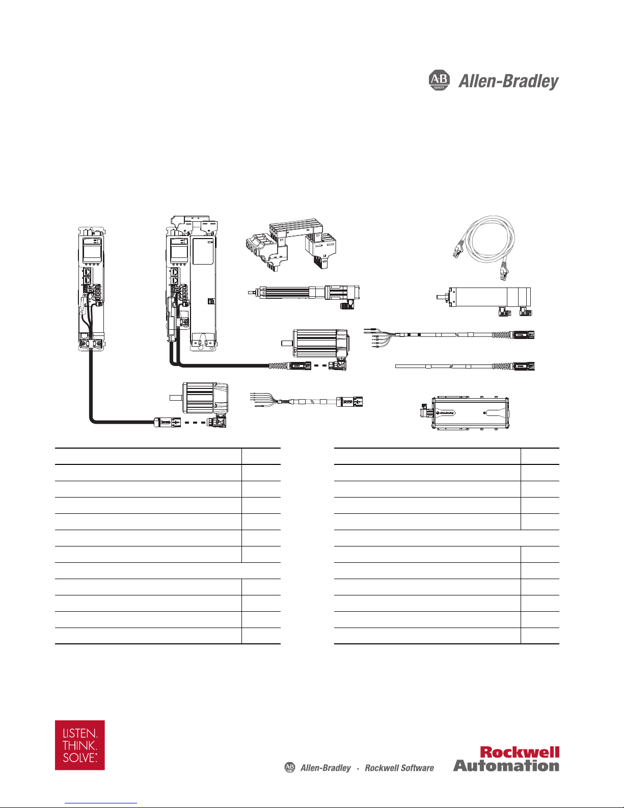
Design Guide
Interface Cables, Connector Kits,
and Other Drive Accessories
Kinetix 5500
Servo Drives
Kinetix VP
Rotary Motors
2090-Series Single Motor Cables
MP-Series
Rotary Motors
Kinetix VP and
MP-Series
Electric Cylinders
MP-Series Linear Stages
2090-Series Motor Power/Brake
and Feedback Cables
Kinetix 5500 Drive Systems
Catalog Numbers 2198-H003-ERS, 2198-H008-ERS, 2198-H015-ERS, 2198-H025-ERS, 2198-H040-ERS, 2198-H070-ERS,
2198-H003-ERS2, 2198-H008-ERS2, 2198-H015-ERS2, 2198-H025-ERS2, 2198-H040-ERS2, 2198-H070-ERS2, 2198-CAPMOD-1300
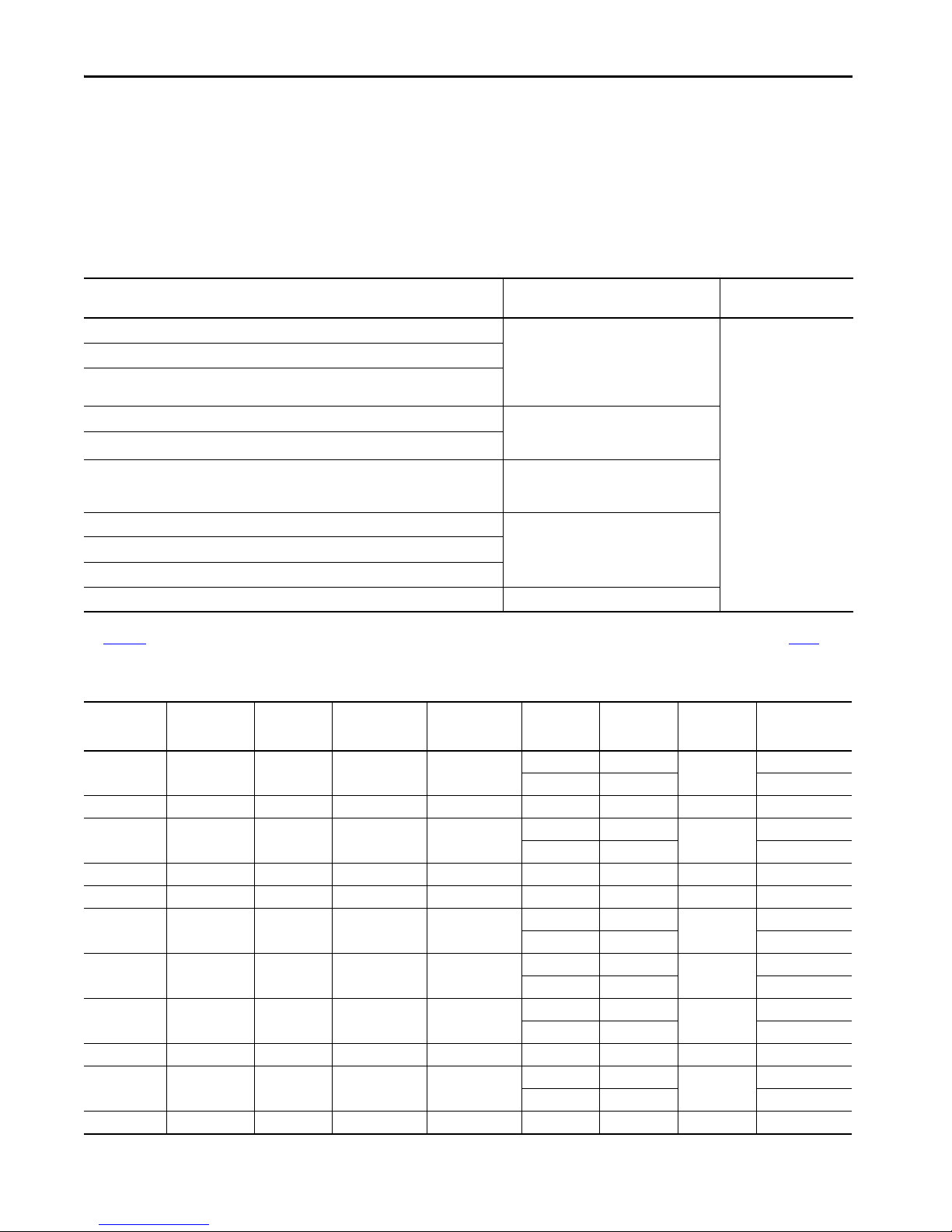
Topic Page Topic, continued Page
Introduction 2 MP-Series Low Inertia Motors 53
Safe Torque-off Configuration Options 3 MP-Series Medium Inertia Motors 64
Determine What You Need 6 MP-Series Food Grade Motors 72
Kinetix 5500 Shared-bus System Examples 10 MP-Series Stainless Steel Motors 77
2090-Series Single Motor Cable Overview 13 Linear Motion System Combinations
2090-Series Motor Power/Brake and Feedback Cables Overview 14 LDAT-Series Integrated Linear Thrusters 80
Rotary Motion System Combinations MP-Series Integrated Linear Stages 101
Kinetix VP Low Inertia Motors 16 Kinetix VP Electric Cylinders 105
Kinetix VP Food Grade Motors 32 MP-Series Electric Cylinders 108
Kinetix VP Hygienic Stainless Steel Motors 43 MP-Series Heavy Duty Electric Cylinders 110
Kinetix VP Stainless Steel Motors 52 Additional Resources 116
Page 2
Kinetix 5500 Drive Systems
Summary of Changes
This publication contains new and updated information as indicated in the following table.
Top ic Page
Added compatibility with CompactLogix™ 5480 controllers. 3
Added compatibility with Kinetix® VP (Bulletin VPAR) electric cylinders.
Added compatibility with Kinetix VP (Bulletin VPH) hygienic stainless-steel ser vo motors.
Added compatibility with 2198-DBRxx-F AC line filters. 9
Corrected motor-rated output values for VPF-B1153E and VPF-B1153F servo motors. 38
Added performance specifications for Bulletin VPH servo motors with Kinetix 5500 drives. 43, 47
Added performance specifications for Bulletin VPAR electric cylinders with Kinetix 5500 drives. 105
7, 8
Introduction
Use this publication if your application includes the Kinetix® 5500 drive family and Kinetix VP motors and actuators or
any of the other compatible Allen-Bradley® motors and actuators. LDAT-Series linear thrusters and MP-Series™ motor
and actuators require the 2198-H2DCK feedback converter kit. For more Kinetix drive and motor information, see the
Kinetix Motion Control Selection Guide, publication KNX-SG001
, or Motion Analyzer software.
The purpose of this publication is to assist you in identifying the drive system components and accessory items you need
for your Kinetix 5500 drive and motor/actuator combination. Diagrams in this publication illustrate how many of the
common drive accessory items are used in a typical system. See the Kinetix Servo Drives Specifications Technical Data,
publication KNX-TD003
, for detailed accessory descriptions and specifications.
Drive/motor system combinations also include the following:
• Motor/cable combinations table
• Drive and motor performance specifications table
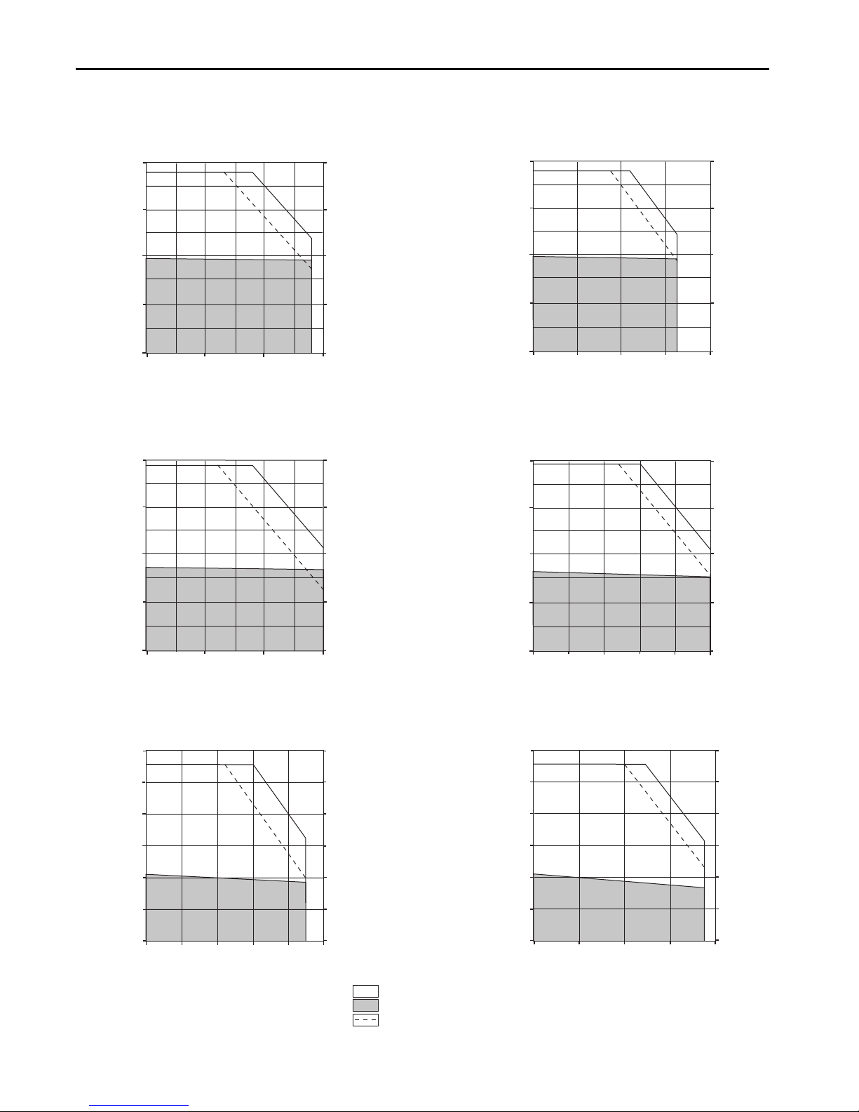
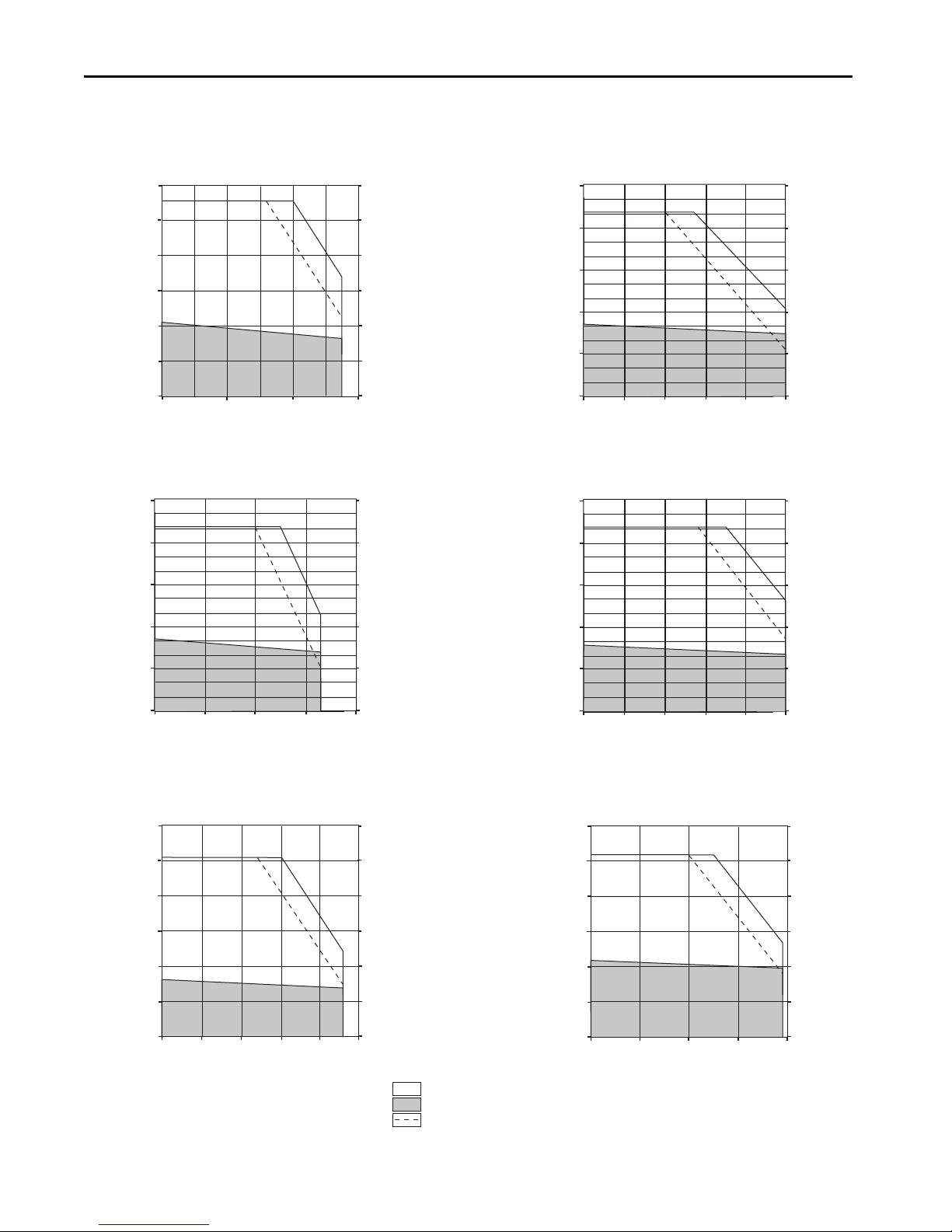
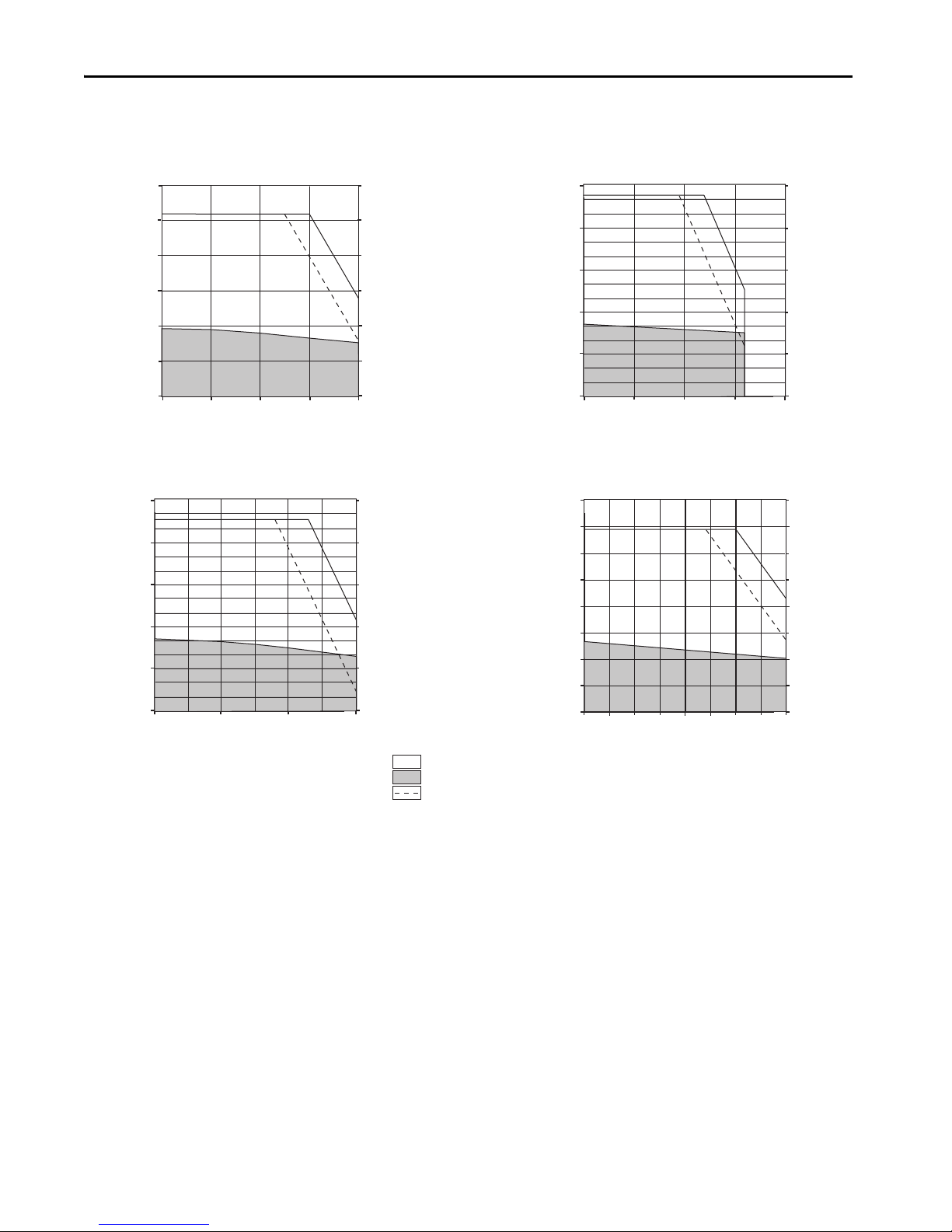
• Torque/speed curves with each motor matched to the drive that provides optimum performance
Performance specification data and curves reflect nominal system performance of a typical system with motor/drive at
rated ambient temperature and line voltage. For additional information on ambients, line conditions, and valid
combinations that are not shown in this publication, refer to the Motion Analyzer system sizing and selection tool.
IMPORTANT These system combinations do not include all possible motor/drive combinations. See the Motion Analyzer system sizing and
selection tool to verify compatibility. Access Motion Analyzer at https://motionanalyzer.rockwellautomation.com.
2 Rockwell Automation Publication KNX-RM009C-EN-P - May 2019
Page 3
Kinetix 5500 Drive Systems
1585J-M8CBJM-x
Ethernet (shielded) Cable
Any Logix 5000™ Controller
(CompactLogix™ 5370 controller is shown)
Studio 5000 Logix Designer®
Application
(version 21.0 or later)
AC Inp ut Power
Safety
Device
2198-Hxxx-ERS Servo Drives
(top view)
2198-Hxxx-ERS Servo Drives
(front view)
Digital Inputs to Sensors and Control String
1606-XLxxx
24V DC Control, Digital Inputs,
and Motor Brake Power
(customer-supplied)
Module Definition
Configured with
Motion-only
Connect ion
Safe Torque-off
(STO) Connectors
ControlLogix® 5570 Controllers or
GuardLogix® 5570 Safety Controllers
ControlLogix 5580 Controllers or
GuardLogix 5580 Safety Controllers
Compac tLogix 5370 Contro llers or
Compact GuardLogix 5370 Safety Controllers
CompactLogix 5380 or 5480 Controllers or
Compact GuardLogix 5380 Safety Controllers
Kinetix VP
Servo Motors
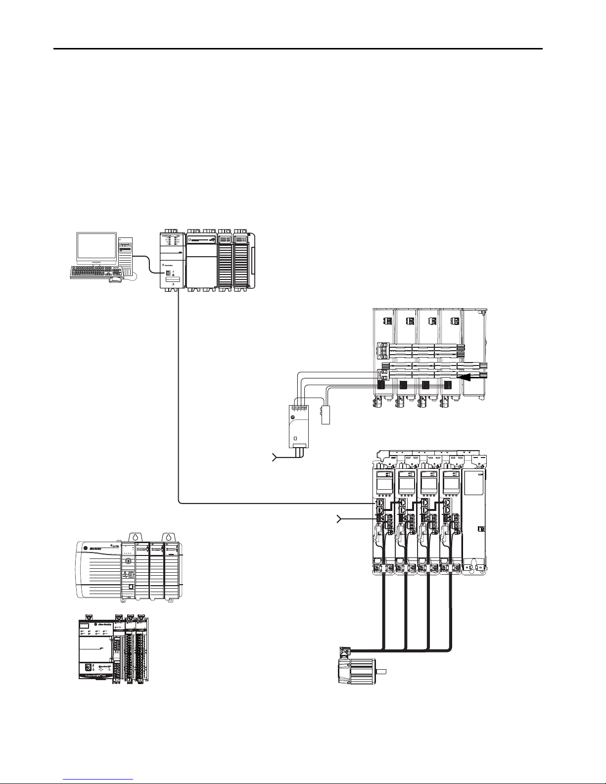
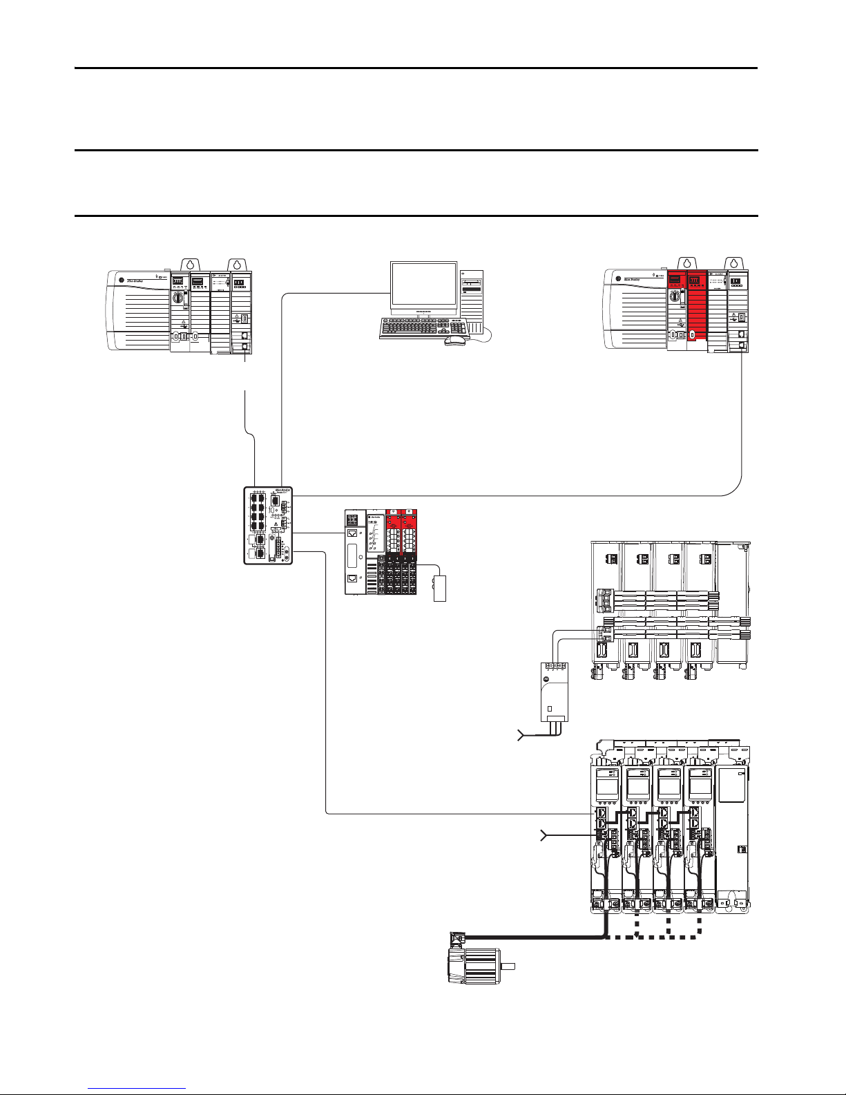
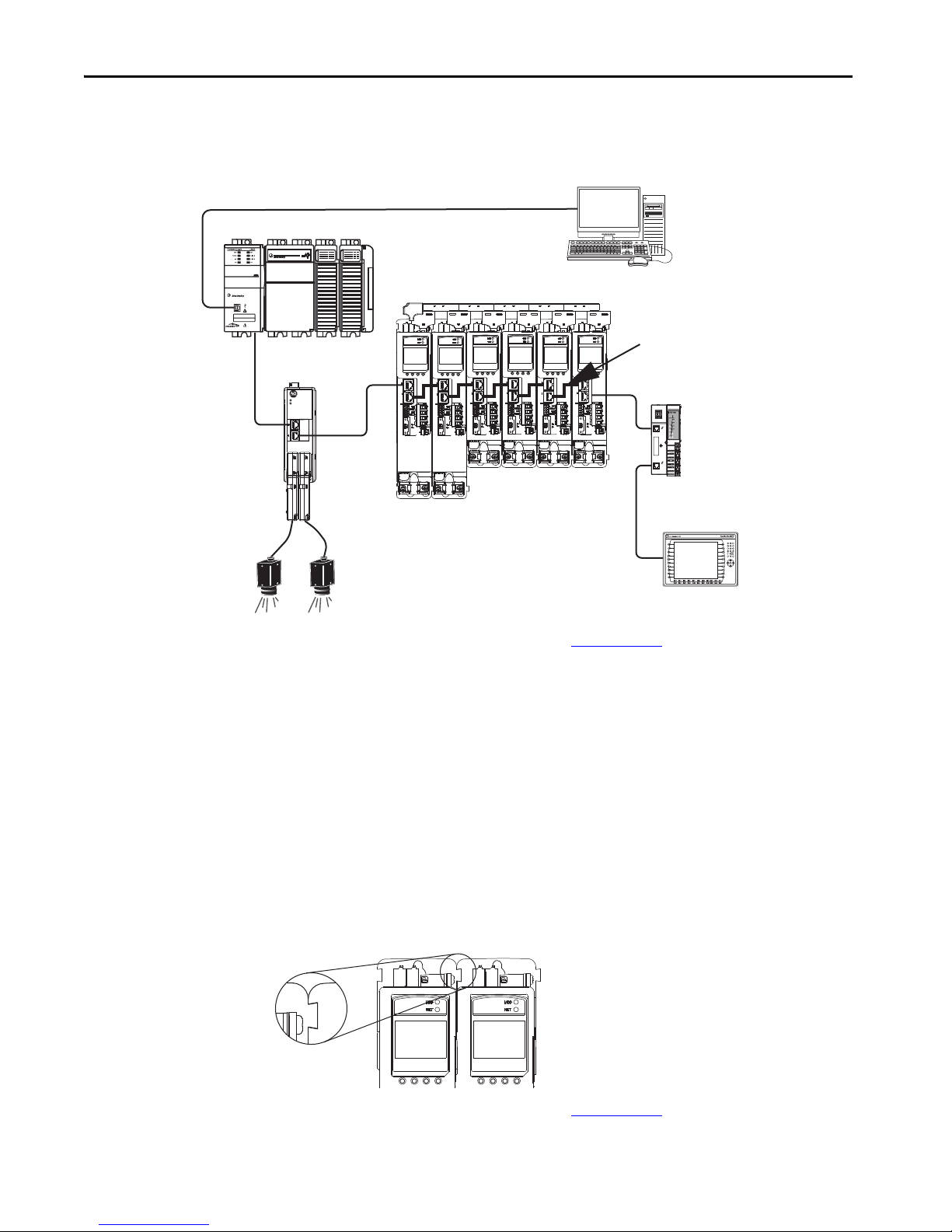
Safe Torque-off Configuration Options
Kinetix 5500 servo drives are available with safe torque-off over hardwired connections or integrated over the
EtherNet/IP™ network. These examples illustrate the safe torque-off configuration options.
Hardwired Safety Configuration
The 2198-Hxxx-ERS drives use the safe torque-off (STO) connector for wiring external safety devices and cascading
hardwired safety connections from one drive to another.
Safe Torque-off (hardwired) Configuration
00:00:BC:2E:69:F6
1 (Front)
2 (Rear)
Logix5585
0000
TM
DC INPUT
SAFETY ON
NET
LINK
OKFORCESDRUN
DC INPUT
AC OUTPUT
Allen-Bradley
Input
1606-XL
Power Supply
Rockwell Automation Publication KNX-RM009C-EN-P - May 2019 3
Page 4
Kinetix 5500 Drive Systems
1606-XL
Power Supply
Input
Allen-Bradley
LNK1LNK2NET OK
EtherNet/IP
1
2
1585J-M8CBJM-x
Ethernet (shielded) Cable
Compact GuardLogix 5370 Controller,
Compact GuardLogix 5380 Safety Controller or
GuardLogix 5570 Controller,
GuardLogix 5580 Safety Controller
(GuardLogix 5570 Safety Controller is shown)
Studio 5000 Logix Designer
Application
(version 24.0 or later)
AC Input Po wer
2198-Hxxx-ERS2 Servo Drives
(top view)
2198-Hxxx-ERS2 Servo Drives
(front view)
Digital Inputs to Sensors and Control String
1606-XLxxx
24V DC Control, Digital Inputs,
and Motor Brake Power
(customer-supplied)
Kinetix VP
Servo Motors
1783-BMS
Stratix® 5700
Switch
Module Definition
Configured with
Motion and Safety
Conne ction
1734-AENTR
POINT Guard I/O™
EtherNet/IP Adapter
Safety
Device
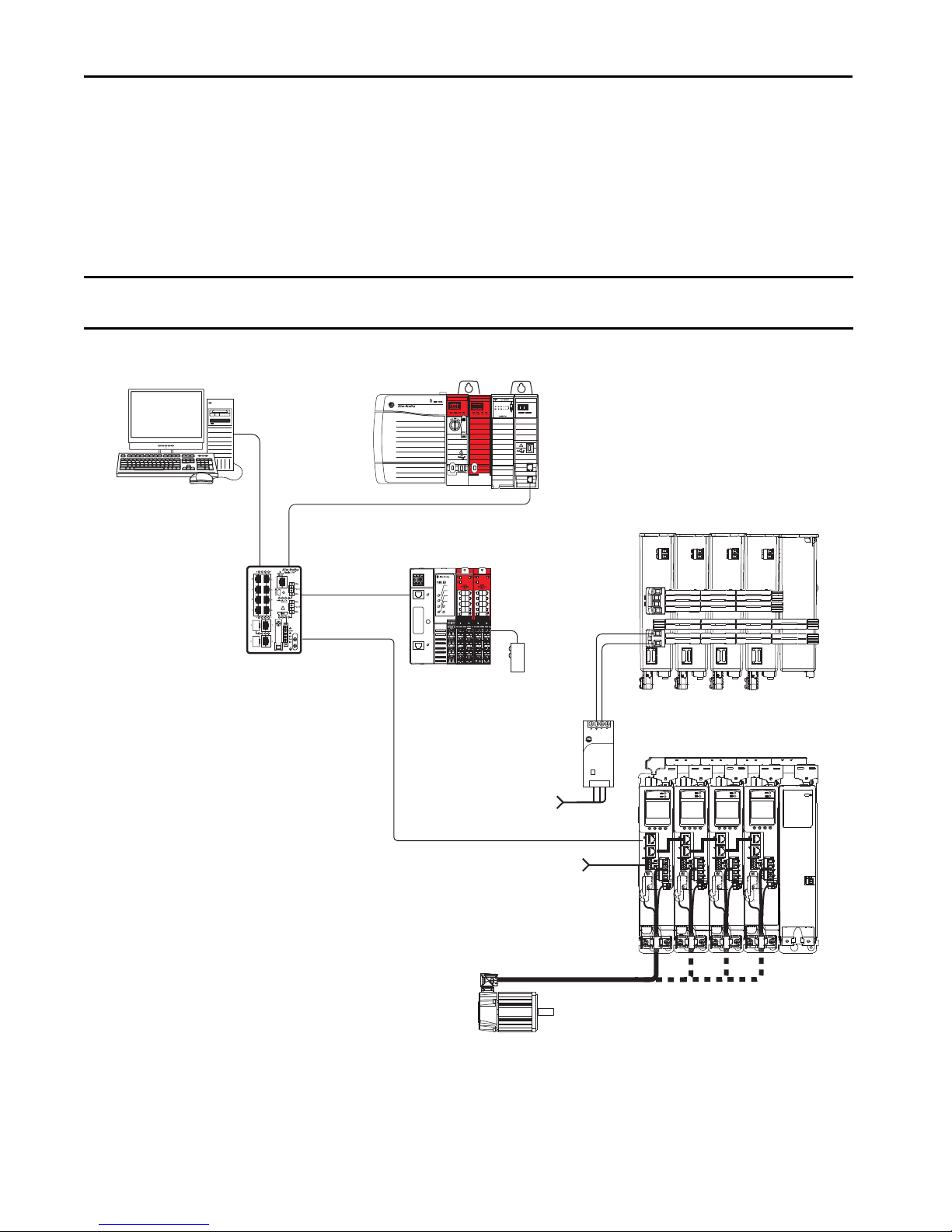
Integrated Safety Configurations
The GuardLogix 5570 or Compact GuardLogix 5370 safety controller issues the safe torque-off (STO) command over
the EtherNet/IP network and the 2198-Hxxx-ERS2 drive executes the STO command.
In this example, a single GuardLogix safety controller makes the Motion and Safety connections with the
2198-Hxxx-ERS2 integrated safety drives.
IMPORTANT If only one controller is used in an application with Motion and Safety connections, it must be a GuardLogix 5570 or Compact
GuardLogix 5370 safety controller.
Motion and Safety Configuration (single controller)
4 Rockwell Automation Publication KNX-RM009C-EN-P - May 2019
Page 5
Kinetix 5500 Drive Systems
1606-XL
Power Supply
Input
Allen-Bradley
LNK1LNK2NET OK
EtherNet/IP
1
2
LNK1LNK2NET OK
EtherNet/IP
1
2
1585J-M8CBJM-x
Ethernet (shielded) Cable
Studio 5000 Logix Designer
Application
(version 24.0 or later)
AC Input Po wer
2198-Hxxx-ERS2 Servo Drives
(top view)
2198-Hxxx-ERS2 Servo Drives
(front view)
Digital Inputs to Sensors and Control String
1606-XLxxx
24V DC Control, Digital Inputs,
and Motor Brake Power
(customer-supplied)
Kinetix VP
Servo Motors
1734-AENTR
POINT Guard I/O
EtherNet/IP Adapter
1783-BMS
Stratix 5700
Switch
Motion Program
Module Definition
Configured with
Motion only
Connect ion
Safety Program
Module Definition
Config ured with S afety
only Connection
Safety
Device
Any Logix 5000™ Controller
(CompactLogix 5370 controller is shown)
Compact GuardLogix 5370 Controller,
Compact GuardLogix 5380 Safety Controller or
GuardLogix 5570 Controller,
GuardLogix 5580 Safety Controller
(GuardLogix 5570 Safety Controller is shown)
In this example, a non-safety controller makes the Motion-only connection and a separate GuardLogix safety controller
makes the Safety-only connection with the 2198-Hxxx-ERS2 integrated safety drives.
IMPORTANT If two controllers are used in an application with Motion-only and Safety-only connections, the Safety-only connection must
be a GuardLogix 5570 or Compact GuardLogix 5370 safety controller and the Motion-only connection must be a
ControlLogix5570 or CompactLogix 5370 controller.
Motion and Safety Configuration (multi-controller)
Rockwell Automation Publication KNX-RM009C-EN-P - May 2019 5
Page 6
Kinetix 5500 Drive Systems
Determine What You Need
For each Kinetix 5500 drive system, the drive and motor/actuator catalog numbers are required to determine the motor
cable catalog number. Ethernet cables and a 24V DC power supply are also required.
• 2198-KITCON-DSL (2-pin) connector kits are used for motor feedback from Kinetix VP motors (highresolution absolute feedback). Kits are included with the drive and can also be purchased separately. Use these kits
with 2090-CSxM1DF or 2090-CSxM1DG cables.
• 2198-H2DCK feedback converter kits (2-pin, Hiperface-to-DSL, series B or later) feedback converter kits are
required for LDAT-series linear thrusters and MP-Series motors and actuators. Use these kits with
2090-CFBM7DF feedback cables.
• Shared-bus connector kits are required for shared-bus configurations.
Optional equipment includes the following:
• Kinetix 5500 capacitor module
• 2198-ABQE encoder output module
• Bulletin 2198 AC line filters
• Bulletin 2097 shunt resistors
Example diagrams of the required and optional equipment are provided.
Kinetix 5500 Servo Drives
Drive Cat. No.
(hardwired STO)
2198-H003-ERS 2198-H003-ERS2
2198-H008-ERS 2198-H008-ERS2
2198-H015-ERS 2198-H015-ERS2
2198-H025-ERS 2198-H025-ERS2
2198-H040-ERS 2198-H040-ERS2
2198-H070-ERS 2198-H070-ERS2 3
Drive Cat. No.
(integrated STO)
Input Voltage
Frame
1
195…264V rms, single-phase
195…264V rms, three-phase
324…528V rms, three-phase
2
195…264V rms, three-phase
324…528V rms, three-phase
Continuous Output
Power
kW
0.2 kW
0.3 kW
0.6 kW
0.5 kW
0.8 kW
1.6 kW
1.0 kW
1.5 KW
3.2 kW
2.4 kW
5.1 kW
4.0 kW
8.3 kW
7.0 kW
14.6 kW
Continuous Output
Current
A 0-pk
1.4
3.5
7.1
11.3
18.4
32.5
Featu res
• Single-axis, single or three-phase
• Multi-axis, three-phase bus-sharing
• Designed for optimum performance
with Kinetix VP servo motors
• Single cable technology
• Safe torque-off
• Single-axis, three-phase
• Multi-axis, three-phase bus-sharing
• Designed for optimum performance
with Kinetix VP servo motors
• Single cable technology
• Safe Torque-off
6 Rockwell Automation Publication KNX-RM009C-EN-P - May 2019
Page 7

Kinetix 5500 Drive Systems
2198-KITCON-DSL Connector Kit
• Accepts DSL motor feedback from Kinetix VP
(Bulletin VPL, VPF, VPH, VPS) rotary motors
and Kinetix VP electric cylinders
• Feedback-only (DSL )
Bulletin 2090 Motor Power and Feedback Cables
MP-Series Linear Actuators
(MPAR-B3xxxx electric cylinder is shown)
MP-Series Rotary Motors
(MPL-Bxxxx motor is shown)
LDAT-Sxxxxxx-xDx
Linear Thrusters
2198-H2DCK Converter Kit
Converts 15-pin Hiperface feedback into 2-pin DSL feedback for:
• MP-Series rotary motors and linear actuators
• LDAT-Series linear thrusters
• Feedback-only (absolute single-turn/multi-turn Hiperface)
2-pin Motor Feedback
(MF) Connector
2198-Hxxx-ERSx Drive
(front view)
MP-Series Linear Actuators
(MPAS-B9xxx ballscrew linear stage is shown)
Kinetix VP Rotary Motors
(VPL-Bxxxx motor is shown)
MP-Series Linear Actuators
(MPAI-B3xxxx heavy-duty electric c ylinder is shown)
Induction Rotary Motors
(no feedback, V/Hz)
2090-CSBM1DF or 2090-CSBM1DG
Single Motor Cables
Kinetix VP Electric Cylinders
(Bulletin VPAR)
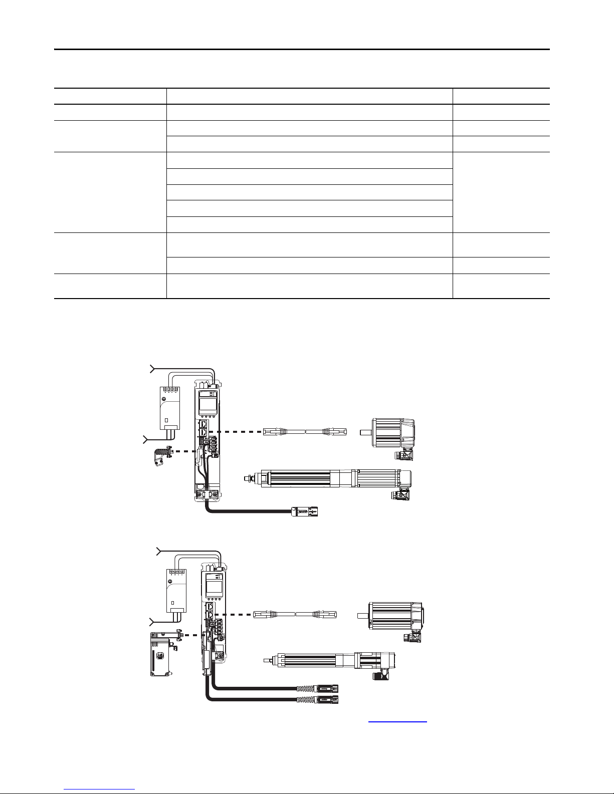
Feedback connections are made at the 2-pin motor feedback (MF) connector. These examples illustrate how you can use
the Bulletin 2198 connector kits for making these connections. These examples illustrate how you can use the Bulletin
2198 connector kits for making these connections.
Feedback Configuration Examples
IMPORTANT In 2198-H2DCK converter kit applications, you can replace the 2090-CPxM7DF power/brake cable with a 2090-CSBM1DF single
motor cable (and reuse the 2090-CFBM7DF feedback cable) to increase the maximum cable length to 50 m (164 ft). However,
this applies to only 18 and 14 AWG single cables. 2090-CSxM1Dx-10Axxx (10 AWG/M40 connector) single cables are not
compatible with 2090-CPBM7DF-10Axxx (10 AWG/M40 connector) power/brake cables.
Rockwell Automation Publication KNX-RM009C-EN-P - May 2019 7
Page 8
Kinetix 5500 Drive Systems
1606-XL
Power Supply
Input
Allen-Bradley
Bulletin 2090 Single Motor Cable
1585J-M8CBJM-x
Ethernet (shielded) Cable
1606-XLxxx
24V DC Control Power Supply
for Control, Digital Inputs,
and Motor Brakes
AC Inp ut Power
Single-phase or Three-phase
AC Input Power
2198-KITCON-DSL
Feedback Connector Kit
2198-Hxxx-ERSx
Kinetix 5500 Servo Drive
Kinetix VP Rotary Motors
(Bulletin VPL motor is shown)
Kinetix VP Linear Actuators
(Bulletin VPAR electric cylinder is shown)
1585J-M8CBJM-x
Ethernet (shielded) Cable
1606-XLxxx
24V DC Control Power Supply
for Control, Digital Inputs,
and Motor Brakes
AC Input Power
Single-phase or Three-phase
AC Input Po wer
Bulletin 2090 Motor Power/Brake
and Feedback Cables
2198-H2DCK (series B or later)
Feedback Converter Kit
2198-Hxxx-ERSx
Kinetix 5500 Servo Drive
MP-Series Rotary Motors
(Bulletin MPL low-inertia motor is shown)
MP-Series Linear Actuators
(Bulletin MPAR electric cylinder is shown)
High-resolution absolute
encoder feedback only.
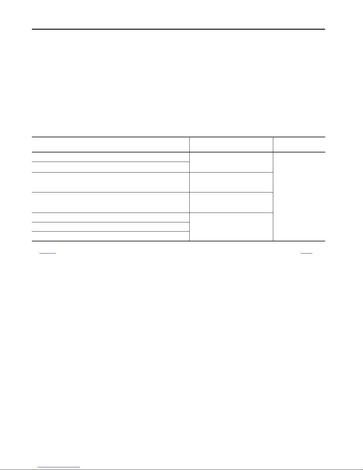
Required Drive Accessories
Drive Accessory Description Cat. No.
24V power supply 24V DC for control power and motor brakes. 1606-XLxxx
Ethernet network cables
Motor cables
Shared-bus connection system
Hiperface-to-DSL
feedback converter kit
(1) The 2198-KITCON-DSL feedback connector kit is required for Kinetix VP motors and actuators and is included with each Kinetix 5500 servo drive. Replacement kits are also available.
(2) The maximum cable length is reduced to 20 m (65.6 ft) for these systems and typical system performance, as documented in this publication, requires the motor and drive at 40 °C (104 °F) ambient
and rated line voltage.
(2)
Double-ended, non-flex, shielded. 1585J-M8CBJM-x
Double-ended, high-flex, shielded. 1585J-M8UBJM-x
Kinetix VP (Bulletin VPL, VPF, VPH, and VPS) rotary motors.
Kinetix VP (Bulletin VPAR) electric cylinders.
(1)
MP-Series (Bulletin MPL, MPM, MPF, and MPS) rotary motors with high-resolution absolute encoders.
MP-Series (Bulletin MPAS ballscrew, MPAR, and MPAI) linear actuators.
(1)
Refer to the specific drive/motor
combination for the motor
cables required for your system.
LDAT-Series linear thrusters.
Input wiring connectors and DC-bus T connectors for use between frame 1, 2, and 3 servo drives
(frame 3:2, frame 2:1, frame 1:1, and frame 2:2). Required for shared-bus configurations.
2198-H040-x-x
Input wiring connectors and DC-bus T connectors for use between frame 3 servo drives (frame 3:3). 2198-H070-x-x
Converts Hiperface high-resolution absolute encoder feedback to Hiperface DSL feedback. Required
for feedback connections to LDAT-Series linear thrusters and MP-Series motors and actuators.
2198-H2DCK
Kinetix 5500 Drive with Kinetix VP Motor
Kinetix 5500 Drive with MP-Series Motor or Actuator
Allen-Bradley
1606-XL
Power Supply
Input
Refer to the Kinetix Servo Drives Specifications Technical Data, publication KNX-TD003, for detailed descriptions and
additional specifications for the Kinetix 5500 drive family.
8 Rockwell Automation Publication KNX-RM009C-EN-P - May 2019
Page 9
Kinetix 5500 Drive Systems
Single-phase or Three-phase
AC Inp ut Power
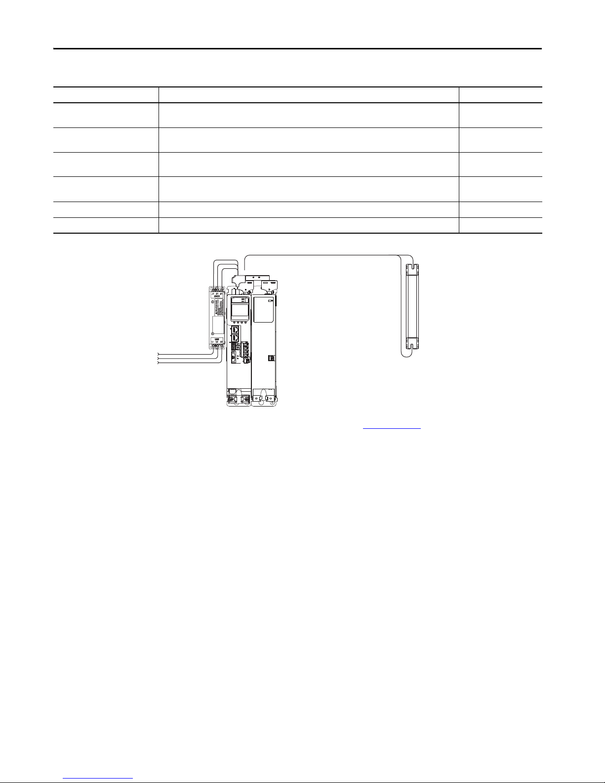
2097-Rx Shunt Resistor
Bulletin 2198 AC Line Filter
(required for CE)
2198-CAPMOD-1300
Capacitor Module
2198-Hxxx-ERSx
Kinetix 5500 Servo Drive
Bulletin 2198 shared-bus connection
system for bus-sharing configurations.
Optional Drive Accessories
Drive Accessory Description Cat. No.
Shared-bus connector kits 24V input wiring connectors, T-connectors, and bus bars for the 24V shared-bus connection system
Capacitor module
Encoder output module
AC line filters AC line conditioning for EMC.
Bulletin 2097 shunt resistor Panel-mount shunt resistor. 2097-Rx
External auxiliary encoders Allen-Bradley Integrated Motion encoder on the EtherNet/IP network provides a feedback-only axis. Bulletin 842E-CM
Capacitor bank for energy storage and/or to improve performance in applications that produce regenerative
energy and require shorter duty cycles (1360 μf).
The Allen-Bradley encoder output module is a DIN-rail mounted EtherNet/IP network-based standalone
module capable of outputting encoder pulses to a customer-supplied peripheral device.
• 2198-TCON-24VDCIN36
• 2198-xxxx-P-T
2198-CAPMOD-1300
2198-ABQE
• 2198-DBRxx-F
• 2198-DBxx-F
Kinetix 5500 Optional Accessories
Refer to the Kinetix Servo Drives Specifications Technical Data, publication KNX-TD003, for detailed descriptions and
additional specifications for the Kinetix 5500 drive accessories.
Rockwell Automation Publication KNX-RM009C-EN-P - May 2019 9
Page 10
Kinetix 5500 Drive Systems
Studio 5000 Logix Designer
Application
1585J-M8CBJM-x
Ethernet (shielded) Cable
1734-AENTR POINT I/O™
EtherNet/IP Adapter
PanelVie w™ Plus
Display Terminal
1585J-M8CBJM-OM15
0.15 m (6 in.) Ethernet cables
for drive-to-drive connections.
Kinetix 5500 Servo Drive System
2198-ABQE
Encoder Output Module
Line Scan
Cameras
CompactLogix 5370 Controller
2198-Hxxx-ERSx Drives
(front view)
Zero-stack Tab
and Cutout Engaged
In this example, the encoder output module outputs encoder pulses to cameras used in line-scan vision systems. The
module supports real and virtual axes for systems using the integrated motion on EtherNet/IP network.
Encoder Output Module Example
00:00:BC:2E:69:F6
1 (Front)
2 (Rear)
MOD
NET
OUTPUT-A OUTPUT-B
1734-AENTR
02
0
POINT I O
Module
Status
Network
Activity
Network
Status
Point Bus
Status
Link 1
Activity/
System
Status
Power
Field
Power
Link 2
Activity/
Status
Refer to the Kinetix Servo Drives Specifications Technical Data, publication KNX-TD003, for detailed descriptions and
additional specifications for the Kinetix 5500 drive accessories.
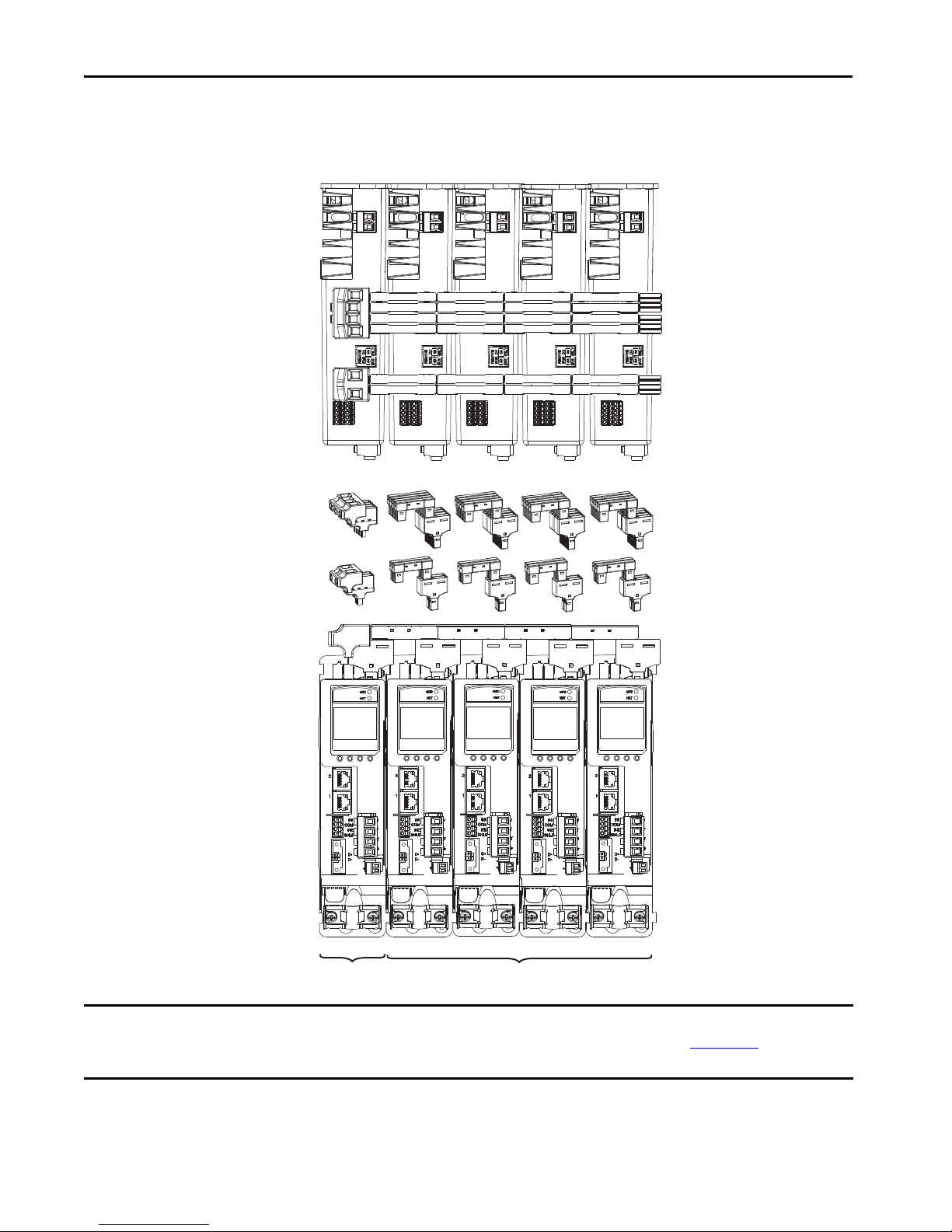
Kinetix 5500 Shared-bus System Examples
These system examples illustrate how Kinetix 5500 servo drives and shared-bus accessories are used in typical shared-bus
configurations. In these examples, frame 1 and 2 drives are used, so the shared-bus accessories are all catalog number
2198-H040-x-x.
Engaging the zero-stack tab and cutout from drive-to-drive makes efficient use of panel space for installations with
multiple drives. Engaging the zero-stack tab and cutout from drive-to-drive is required for shared-bus multi-axis drive
systems. This is done to make sure the drive connectors are spaced properly to accept the shared-bus connection system.
Zero-stack Tab and Cutout Example
Refer to the Kinetix Servo Drives Specifications Technical Data, publication KNX-TD003, for detailed descriptions and
catalog numbers for the shared-bus connector kits.
10 Rockwell Automation Publication KNX-RM009C-EN-P - May 2019
Page 11
In this example, three-phase AC power and 24V control power is shared in a shared-AC configuration. All drives must
+
+
++
Kinetix 5500 Servo Drives (top view)
2198-H008-ERS (frame 1) Drives are Shown
Three-phase
Input Power
Kinetix 5500 Servo Drives (front view)
2198-H008-ERS (frame 1) Drives are Shown
Shared AC ( mains AC inpu t)
Shared 24V (control power input)
Shared-bus Connection System
(front view)
AC Inp ut
Connector
Control Power
Input Connector
Bus-bar Connectors and
AC Bus T-connectors
Bus-bar Connectors and
Control Power T-connectors
24V Control
Input Power
Axis 1 Axis 2
Axis 3
Axis 4 Axis 5
2198-H040-ADP-IN 2198-H040-AP-T
The 2198-H040-ADP-IN
connector kit also includes a
DC-bus T-connector, but is not
used in this configuration.
have the same power rating (catalog number).
Shared AC Installation Example
Kinetix 5500 Drive Systems
IMPORTANT In shared AC configurations, all drives must have the same power rating. Shared AC configurations do not support the
Bulletin 2198 capacitor module. Refer to the Kinetix 5500 Servo Drives User Manual, publication 2198-UM001
information, including restrictions on how many drives can be connected in the shared AC configuration.
, for system sizing
Rockwell Automation Publication KNX-RM009C-EN-P - May 2019 11
Page 12

Kinetix 5500 Drive Systems
++++
++
2198-H040-ERSx
Common-bus (converter)
(frame 2) Leader Drives
2198-H008-ERSx
Common-bus (inverter)
(frame 1) Follower Drives
2198-CAPMOD-1300 Capacitor Module
(optional component) Front View
2198-CAPMOD-1300 Capacitor Module
(optional component) Top View
2198-Hxxx-ERS
Kinetix 5500 Servo Drives are Shown
(top view)
Three-phase
Input Power
Shared AC (mains AC input)
Shared 24V (control power input)
Shared-bus Connection System
(front view)
AC Input
Conne ctor
Control Power
Input Connector
Bus-bar Connectors and
AC Bus T-connectors
Bus-bar Connectors and
Control Power T-connectors
24V Control Input Power
Axis 1
Axis 2
Axis 3
Axis 4
Axis 5
2198-H040-ADP-IN
DC Bus
Shared DC Bus
DC Bus
Connector
Bus-bar Connectors and
DC Bus T-connectors
2198-Hxxx-ERS
Kinetix 5500 Servo Drives are Shown
(front view)
Axis 6
2198-H040-ADP-T
2198-H040-DP-T
2198-KITCON-CAP1300
(ships with capacitor module)
In this example, three-phase AC input power is supplied to two converter drives with the same power rating. This parallel
converter configuration increases the DC power supplied to the inverter drives.
Shared AC/DC Bus Hybrid Installation Example
IMPORTANT In shared AC/DC hybrid configurations, the two converter drives must have the same power rating and must be greater than or
equal to the inverter drives. Refer to the Kinetix 5500 Servo Drives User Manual, publication 2198-UM001
information, including restrictions on how many drives can be connected in the shared AC/DC, shared DC (common bus), and
hybrid configurations.
12 Rockwell Automation Publication KNX-RM009C-EN-P - May 2019
, for system sizing
Page 13
Kinetix 5500 Drive Systems
2090-Series Single Motor Cable Overview
These cables apply to Kinetix VP rotary motors and linear actuators. When using single cables, system performance of a
typical system with the motor at 40 °C (104 °F) and drive at 50 °C (122 °F) ambient applies. For maximum motor-cable
lengths with Kinetix 5500 drives, see the Kinetix 5500 Servo Drives User Manual, publication 2198-UM001
IMPORTANT Because of the unique characteristics of single cable technology, building your own cables, using field modified Rockwell
Automation® factory-delivered cable, or using third-party cables with Kinetix VP (Bulletin VPL, VPF, VPH, and VPS) motors and
Bulletin VPAR electric cylinders is not an option.
2090-CSxM1DF cable conductors have flying-leads and lead preparation that is designed specifically for Kinetix 5500
servo drives. No on-site lead preparation is required. 2090-CSxM1DG cable conductors have flying-leads and lead
preparation that is designed for either Kinetix 5500 or Kinetix 5700 servo drives. No on-site lead preparation is required;
however, 2090-CSxM1DG cable leads are longer than 2090-CSxM1DF cable leads to accommodate either drive family.
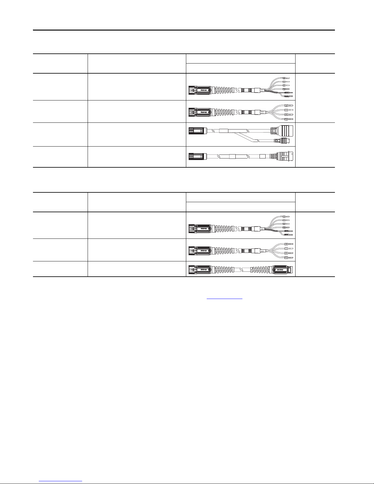
Single Motor Cable Descriptions
.
Single Cable Cat. No. Description
2090-CSBM1DF-xxAAxx
2090-CSBM1DF-xxAFxx
2090-CSBM1DG-xxAAxx
2090-CSBM1DG-xxAFxx
2090-CSWM1DF-xxAAxx
2090-CSWM1DG-xxAAxx
• Drive-end flying-leads (DF) (DG = longer lead lengths)
• Power/feedback/brake wires (SB)
• Standard, non-flex (AA)
• Continuous-flex (AF)
• Drive-end flying-leads (DF) (DG = longer lead lengths)
• Power/feedback wires only (SW)
Motor End Drive End
Cable Configuration
Motor Connector
SpeedTec DIN
Single extension cables provide continuous-flex cable technology between your standard (non-flex) cable and the
continuous-flex application. The IP rating for continuous-flex extension cables is consistent with the motor/actuator and
cable combination they are extending. Extension cables are available in lengths up to 30 m (98.4 ft). Extension power
cables are available in 18, 14, and 10 AWG.
Single Extension Cable Descriptions
Cable Cat. No. Description
2090-CSBM1E1-xxAFxx
(1) SpeedTec DIN connector (motor end) and male connector for extending SpeedTec DIN cable.
• Drive-end (male) connector, extension (E1)
• Motor-end SpeedTec DIN cable plug (M1)
(1)
Motor End Drive End
Cable Configuration
Motor Connector
SpeedTec DIN
Refer to the Kinetix Motion Accessories Technical Data, publication KNX-TD004, for cable specifications.
Rockwell Automation Publication KNX-RM009C-EN-P - May 2019 13
Page 14
Kinetix 5500 Drive Systems
2090-Series Motor Power/Brake and Feedback Cables Overview
These cables apply to LDAT-Series linear thrusters and MP-Series motors and actuators with high-resolution absolute
encoders. When using these cables, system performance of a typical system with the motor/actuator at 40 °C (104 °F)
and drive at 40 °C (104 °F) ambient applies. Maximum motor power cable length is 20 m (65.6 ft) for Kinetix 5500 drive
systems using these cables.
IMPORTANT To increase the maximum motor power cable length to 50 m (164 ft) and the system ambient to motor at 40 °C (104 °F) and
drive at 50 °C (122 °F), use the 2090-CSBM1DF (single) cable for motor power/brake, and the 2090-CFBM7DF cable for motor
feedback.
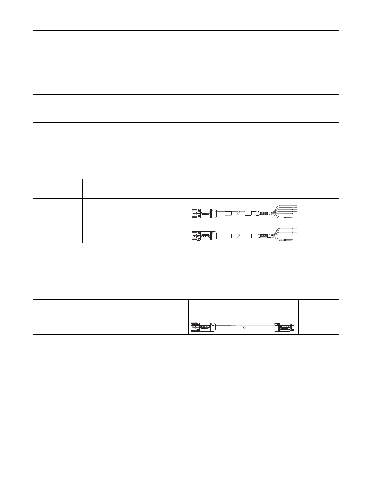
Feedback Cable Descriptions (standard, non-flex)
Standard Cable
Cat. No.
2090-CFBM7DF-CEAAxx
2090-CFBM4E2-CATR
(1) Threaded DIN connector (motor end) and bayonet connector for 2090-XXNFMP-Sxx cable.
Description
• Drive-end flying-leads (DF)
• High-resolution or resolver applications (CE)
• Drive-end bayonet (E2), transition (TR) cable
• Motor-end threaded DIN (M4)
• All feedback types (CA)
Motor/Actuator End Drive End
(1)
Cable Configuration
Motor/Actuator
Connector
SpeedTec DIN
(M7)
Threaded DIN
(M4)
Feedback Cable Descriptions (continuous-flex)
Continuous-flex Cable
Cat. No.
2090-CFBM7DF-CDAFxx
2090-CFBM7DF-CEAFxx
2090-CFBM7E7-CDAFxx
2090-CFBM7E7-CEAFxx
(1) SpeedTec DIN connector (motor end) and male connector for extending SpeedTec or threaded DIN cable.
Description
• Drive-end flying-leads (DF)
• High-resolution or incremental applications (CD)
• Drive-end flying-leads (DF)
• High-resolution or resolver applications (CE)
• Drive-end (male) connector, extension (E7)
• Motor-end SpeedTec DIN cable plug (M7)
(1)
Motor/Actuator End Drive End
Cable Configuration
Motor/Actuator
Connector
SpeedTec DIN
(M7)
Motor-end cable connector kits, for use when building your own cables are also available. Refer to the Kinetix Motion
Accessories Technical Data, publication KNX-TD004
, for more information.
14 Rockwell Automation Publication KNX-RM009C-EN-P - May 2019
Page 15
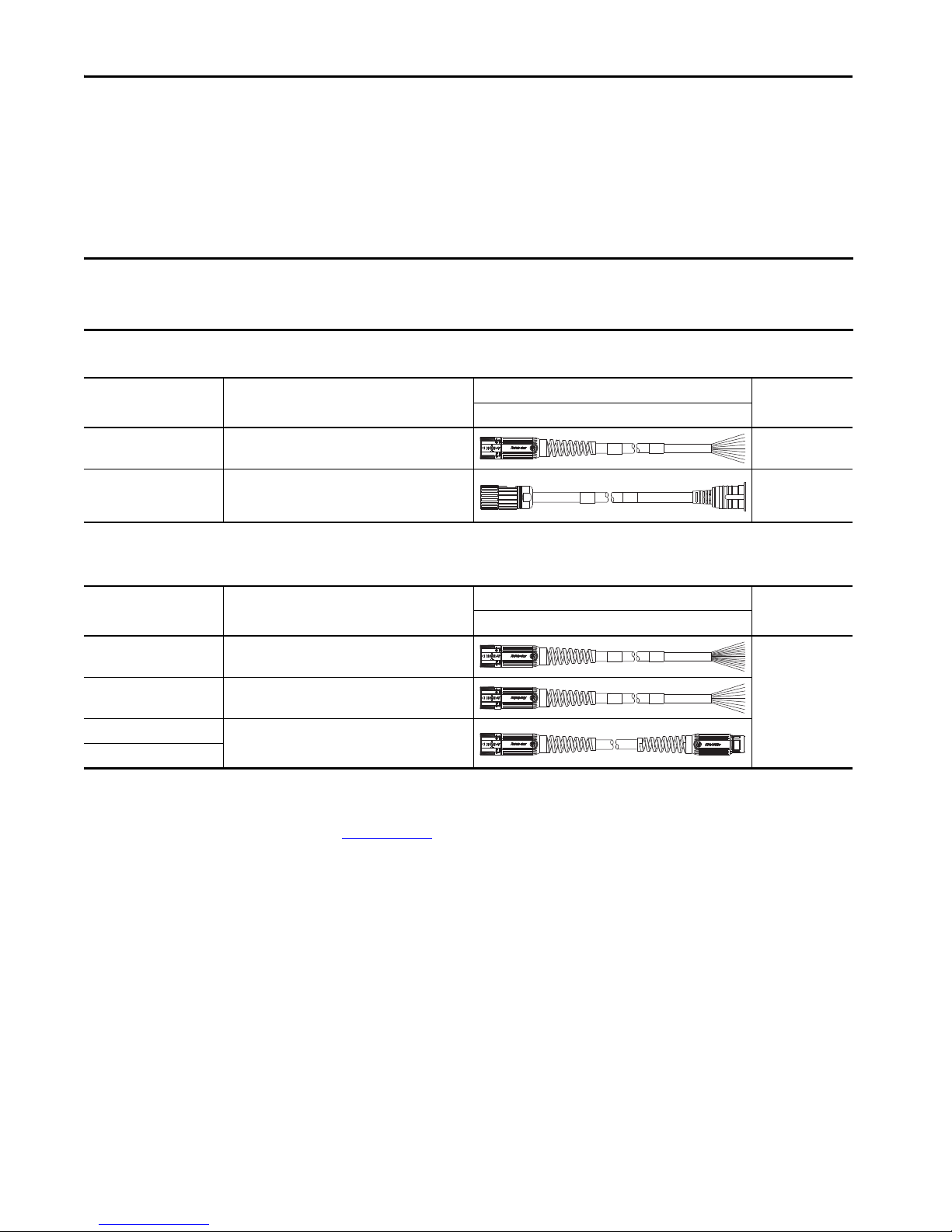
Power/Brake Cable Descriptions (standard, non-flex)
Kinetix 5500 Drive Systems
Standard Cable
Cat. No.
2090-CPBM7DF-xxAAxx
2090-CPWM7DF-xxAAxx
Description
• Drive-end flying-leads (DF)
• Power/brake wires (PB)
• Drive-end flying-leads (DF)
• Power wire s only (PW)
• Drive-end bayonet (E2), transition (TR) cable
2090-CPBM4E2-xxTR
• Motor-end threaded DIN (M4)
• Power/brake wires (PB)
• Drive-end bayonet (E2), transition (TR) cable
2090-CPWM4E2-xxTR
• Motor-end threaded DIN (M4)
• Power wire s only (PW)
(1) Threaded DIN connector (motor end) and bayonet connector for 2090-XXNFMP-Sxx cable.
Power/Brake Cable Descriptions (continuous-flex)
Continuous-flex Cable
Cat. No.
2090-CPBM7DF-xxAFxx
Description
• Drive-end flying-leads (DF)
• Power/brake wires (PB)
Cable Configuration
Motor/Actuator End Drive End
(1)
(1)
Cable Configuration
Motor/Actuator End Drive End
Motor/Actuator
Connector
SpeedTec DIN
(M7)
Threaded DIN
(M4)
Motor/Actuator
Connector
SpeedTec DIN
2090-CPWM7DF-xxAFxx
2090-CPBM7E7-xxAFxx
(1) SpeedTec DIN connector (motor end) and male connector for extending SpeedTec or threaded DIN cable.
• Drive-end flying-leads (DF)
• Power wire s only (PW)
• Drive-end (male) connector, extension (E7)
• Motor-end SpeedTec DIN cable plug (M7)
(1)
(M7)
Refer to the Kinetix Motion Accessories Technical Data, publication KNX-TD004, for cable specifications.
Rockwell Automation Publication KNX-RM009C-EN-P - May 2019 15
Page 16
Kinetix 5500 Drive Systems
Kinetix 5500 (200V-class operation) Drives with Kinetix VP Low Inertia Motors
This section provides system combination information for the Kinetix 5500 drives (with 200 and 240V, nominal input)
when matched with Kinetix VP (200V-class) low-inertia motors. Single cable catalog numbers, system performance
specifications, and the optimum torque/speed curves are included.
Kinetix 5500 servo drives are capable of 200V or 400V-class operation. These system performance tables and torque/
speed curves reflect single-phase and three-phase drive operation with 200V-class motors; however, only 2198-H003ERSx, 2198-H008-ERSx, and 2198-H015-ERSx drives are capable of single-phase operation.
Bulletin VPL Motor Cable Combinations
Rotary Motor (200V-class)
Cat. No.
VPL-A063xx 2090-CSBM1Dx-18AAxx or
VPL-A0751E, VPL-A0752C, VPL-A0753C
VPL-A0752E, VPL-A0753E
VPL-A1001C
VPL-A1001M, VPL-A1002x, VPL-A1003x
VPL-A1152x, VPL-A1153x
VPL-A1303x, VPL-A1304x, VPL-A1306x
(1) Use 2090-CSxM1DF or 2090-CSxM1DG cables. Cable length xx is in meters, 01 (3.3)…50 (164) in 1.0 m (3.3 f t) increments. Refer to the Kinetix Motion Accessories Technical Data, publication
KNX-TD004
, for cable specifications. For cable configuration illustrations and feature descriptions, by catalog number, refer to 2090-Series Single Motor Cable Overview beginning on page 13.
Single Cable Cat. No.
2090-CSWM1Dx-18AAxx (standard, non-flex)
2090-CSBM1Dx-18AFxx (continuous-flex)
2090-CSBM1Dx-14AAxx or
2090-CSWM1Dx-14AAxx (standard, non-flex)
2090-CSBM1Dx-14AFxx (continuous-flex)
2090-CSBM1Dx-18AAxx or
2090-CSWM1Dx-18AAxx (standard, non-flex)
2090-CSBM1Dx-18AFxx (continuous-flex)
2090-CSBM1Dx-14AAxx or
2090-CSWM1Dx-14AAxx (standard, non-flex)
2090-CSBM1Dx-14AFxx (continuous-flex)
(1)
Feedback Type
Multi-turn or Single-turn
Digital Encoder Feedback
16 Rockwell Automation Publication KNX-RM009C-EN-P - May 2019
Page 17

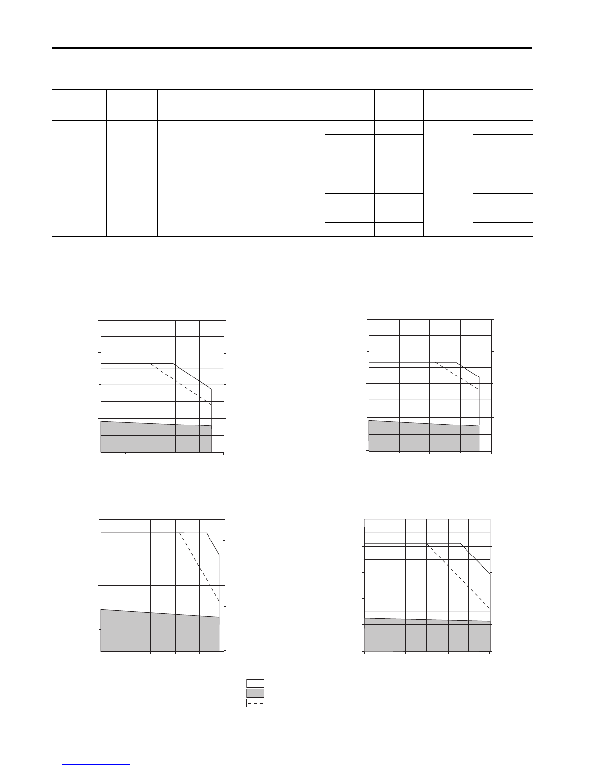
Bulletin VPL Motor Performance Specifications with Kinetix 5500 (200V-class operation) Drives
Kinetix 5500 Drive Systems
Rotary Motor
Cat. No.
VPL-A0631E 4500 4500 1.20 0.46 (4.0)
VPL-A0631M 7200 7200 1.92 0.46 (4.0) 6.48 1.33 (12.0) 0.28 (0.38) 2198-H008-ERSx
VPL-A0632F 4800 4800 2.55 0.93 (8.0) 8.75 2.69 (24.0) 0.39 (0.52) 2198-H008-ERSx
VPL-A0633C 3000 3000 2.50 1.27 (11.0) 8.75 4.09 (36.0) 0.37 (0.50) 2198-H008-ERSx
VPL-A0633F 4500 4500 3.52 1.27 (11.0)
VPL-A0751E 4800 4800 2.90 1.01 (9.0)
VPL-A0752C 3300 3300 3.80 1.61 (14.0) 13.30 4.39 (39.0) 0.49 (0.66) 2198-H015-ERSx
VPL-A0752E 4800 4800 4.90 1.61 (14.0)
VPL-A0753C 3300 3300 4.90 2.16 (19.0)
VPL-A0753E 4600 4600 6.12 2.28 (20.0)
VPL-A1001C 2800 2800 3.61 1.93 (17.0)
VPL-A1001M 6500 6500 7.15 1.95 (17.0)
VPL-A1002C 3000 3000 6.24 3.39 (30.0)
VPL-A1002F 5000 5000 10.04 3.26 (29.0)
VPL-A1003C 2250 2250 6.14 4.18 (37.0)
VPL-A1003E 3750 3750 9.58 4.18 (37.0)
VPL-A1003F 5500 5500 15.62 4.18 (37.0)
VPL-A1152B 2150 2150 6.17 5.10 (45.0)
VPL-A1152E 3300 3300 10.60 5.08 (45.0)
VPL-A1152F 5000 5000 13.56 4.70 (42.0) 45.80 13.12 (116) 2.16 (2.90) 2198-H040-ERSx
VPL-A1153C 2300 2300 8.88 6.55 (58.0)
VPL-A1303B 1950 1950 10.34 8.80 (78.0)
Rated Speed
rpm
Speed, max
rpm
System Cont inuous
Stall Current
A 0-pk
System Continuous
Stall Torque
N•m (lb•in)
System Peak
Stall Current
A 0-pk
3.50 1.12 (9.91)
4.20 1.33 (12.0) 2198-H008-ERSx
8.80 2.87 (25.0)
12.60 4.09 (36.0) 2198-H015-ERSx
8.80 2.20 (19.0)
9.12 2.27 (20.0) 2198-H015-ERSx
17.70 4.10 (36.0)
18.90 4.39 (39.0) 2198-H025-ERSx
17.70 6.55 (58.0)
18.90 7.02 (62.0) 2198-H025-ERSx
17.70 5.13 (45.0)
25.34 7.35 (65.0) 2198-H025-ERSx
8.80 3.22 (28.0)
10.38 3.78 (33.0) 2198-H015-ERSx
17.70 3.31 (29.0)
20.20 3.78 (33.0) 2198-H025-ERSx
17.70 6.80 (60.0)
20.33 7.82 (69.0) 2198-H025-ERSx
28.30 6.77 (60.0)
34.30 7.82 (69.0) 2198-H040-ERSx
17.70 9.76 (86.0)
20.20 11.15 (99.0) 2198-H025-ERSx
28.30 9.76 (86.0)
28.80 11.15 (99.0) 2198-H040-ERSx
45.90 10.25 (90.0)
50.0 11.15 (99.0) 2198-H070-ERSx
17.70 10.95 (96.0)
21.19 13.12 (116) 2198-H025-ERSx
28.30 12.14 (107)
32.10 13.12 (116) 2198-H040-ERSx
28.30 18.30 (162)
33.0 20.33 (180) 2198-H040-ERSx
28.30 19.85 (175)
31.0 20.72 (183) 2198-H040-ERSx
System Peak
Stall Torque
N•m (lb•in)
Motor Rated
Output
kW (Hp)
0.19 (0.25)
0.44 (0.59)
0.50 (0.67)
0.66 (0.88)
0.59 (0.79)
0.80 (1.07)
0.56 (0.75)
1.29 (1.73)
1.03 (1.38)
1.60 (2.14)
0.87 (1.17)
1.31 (1.76)
1.90 (2.55)
1.02 (1.37)
1.47 (1.97)
1.35 (1.81)
1.61 (2.16)
Kinetix 5500 Drives
(240V AC Input)
2198-H003-ERSx
2198-H008-ERSx
2198-H008-ERSx
2198-H015-ERSx
2198-H015-ERSx
2198-H015-ERSx
2198-H008-ERSx
2198-H015-ERSx
2198-H015-ERSx
2198-H025-ERSx
2198-H015-ERSx
2198-H025-ERSx
2198-H040-ERSx
2198-H015-ERSx
2198-H025-ERSx
2198-H025-ERSx
2198-H025-ERSx
Rockwell Automation Publication KNX-RM009C-EN-P - May 2019 17
Page 18
Kinetix 5500 Drive Systems
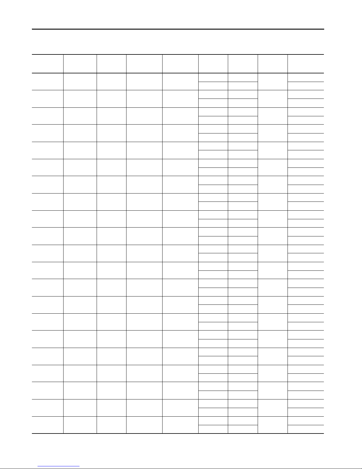
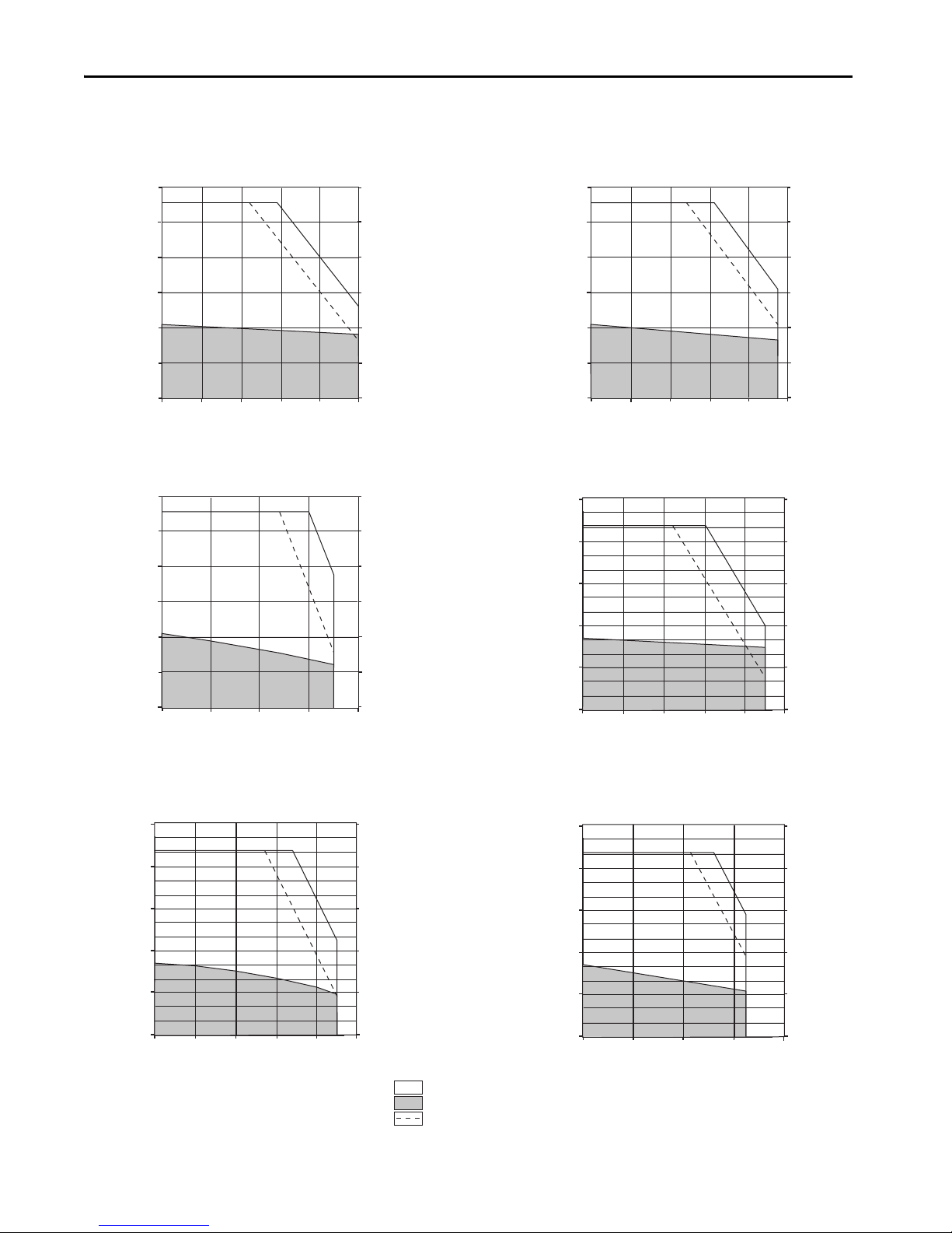
Torque
(N•m)
Torque
(lb•in)
Speed (rpm)
2198-H008-ERSx and VPL-A0631M
2.0
1.5
1.0
0.5
0
0
4000
8000
60002000
17.7
13.3
8.85
4.42
0
Torque
(N•m)
Torque
(lb•in)
Speed (rpm)
2198-H008-ERS
x and VPL-A0631E
17.7
13.3
8.85
4.42
0
2.0
1.5
1.0
0.5
0
0
3000
5000
40001000
2000
Torque
(N•m)
Torque
(lb•in)
0
0
1.0
2.0
3.0
5.0
4.0
8.85
17.7
26.5
35.4
44.2
2198-H008-ERS
x and VPL-A0633C
Speed (rpm)
0
2000
30001000
Torque
(N•m)
Torque
(lb•in)
2198-H008-ERS
x and VPL-A0632F
3.0
2.5
2.0
1.5
1.0
0.5
0
Speed (rpm)
0
3000
5000
4000
1000
2000
26.5
22.1
17.7
13.3
8.85
4.42
0
= Intermittent operating region
= Continuous operating region
= Drive operation with 200V AC rms input voltage
Bulletin VPL Motor Performance Specifications with Kinetix 5500 (200V-class operation) Drives (cont.)
Rotary Motor
Cat. No.
VPL-A1303F 4000 4000 18.60 7.75 (69.0)
VPL-A1304A 1600 1600 9.43 10.29 (91.0)
VPL-A1304D 3000 3000 18.40 10.20 (90.0)
VPL-A1306C 2000 2000 14.78 13.38 (118)
Performance specification data and curves reflect nominal sys tem performance of a typical system with the motor at 40 °C (104 °F) and the drive at 50 °C (122 °F) ambient, and rated line voltage. For
additional information on ambient and line conditions, refer to Motion Analyzer software.
Rated Speed
rpm
Speed, max
rpm
System Cont inuous
Stall Current
A 0-pk
System Continuous
Stall Torque
N•m (lb•in)
System Peak
Stall Current
A 0-pk
45.90 15.36 (136)
62.0 20.72 (183) 2198-H070-ERSx
28.30 25.03 (221)
33.76 28.45 (252) 2198-H040-ERSx
45.90 21.48 (190)
58.0 27.10 (240) 2198-H070-ERSx
45.90 28.50 (252)
55.83 34.62 (306) 2198-H070-ERSx
System Peak
Stall Torque
N•m (lb•in)
Motor Rated
Output
kW (Hp)
2.50 (3.35)
1.55 (2.08)
2.60 (3.50)
2.13 (2.86)
Kinetix 5500 Drives
(240V AC Input)
2198-H040-ERSx
2198-H025-ERSx
2198-H040-ERSx
2198-H040-ERSx
Kinetix 5500 (200V-class operation) Drives/Kinetix VP Low Inertia Motor Curves
18 Rockwell Automation Publication KNX-RM009C-EN-P - May 2019
Page 19
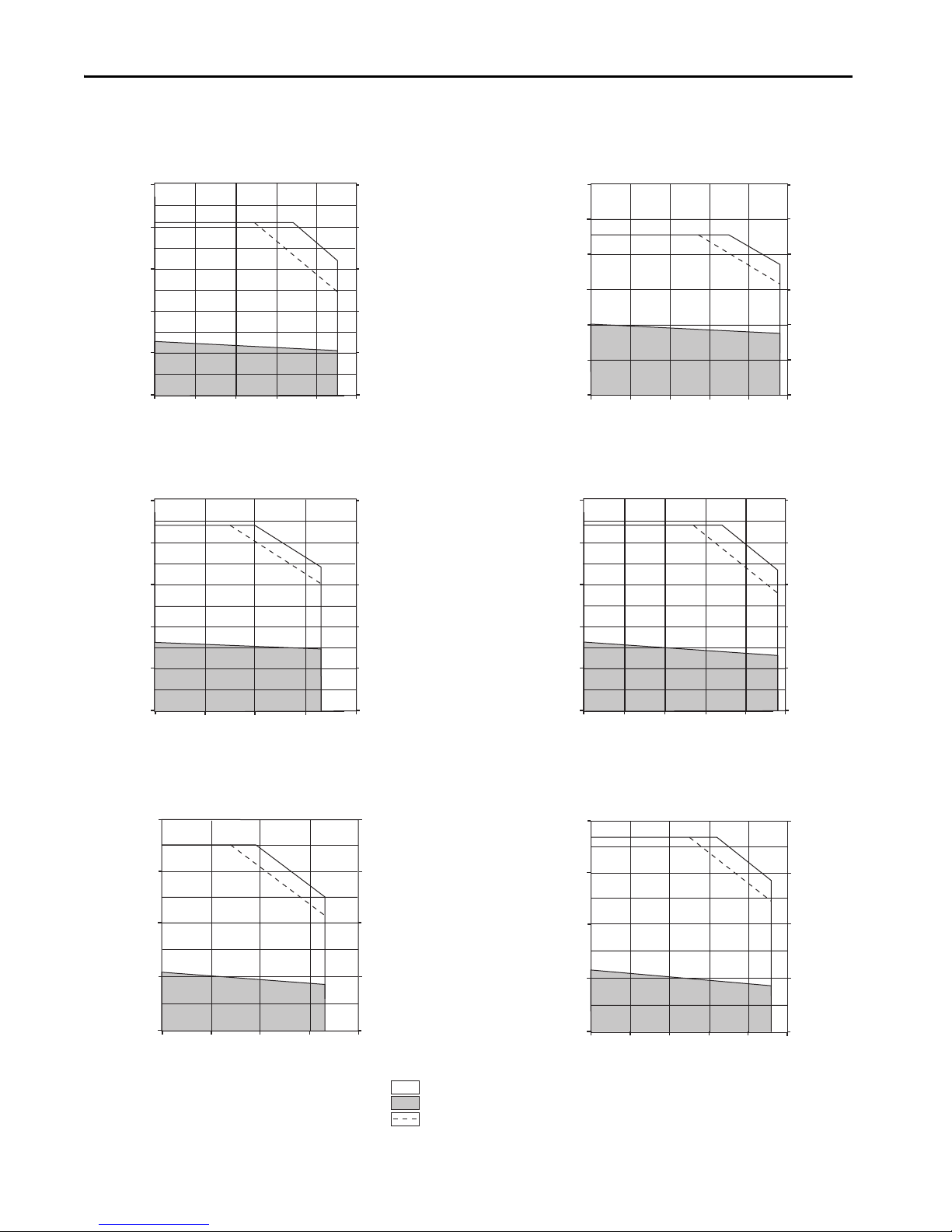
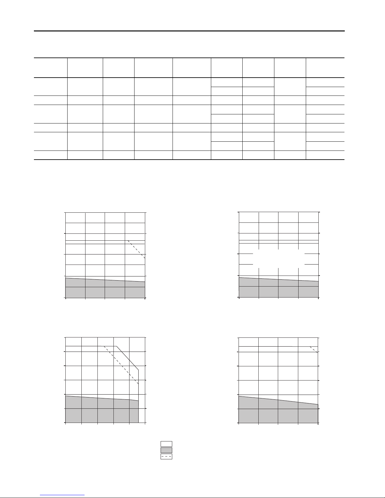
Kinetix 5500 (200V-class operation) Drives/Kinetix VP Low Inertia Motor Curves (continued)
Torque
(N•m)
Torque
(lb•in)
0
0
1.0
2.0
3.0
5.0
4.0
8.85
17.7
26.5
35.4
44.2
2198-H015-ERSx and VPL-A0633F
Speed (rpm)
0
3000
5000
4000
1000
2000
Torque
(N•m)
Torque
(lb•in)
2198-H015-ERSx and VPL-A0751E
3.0
2.5
2.0
1.5
1.0
0.5
0
Speed (rpm)
0
3000
5000
4000
1000
2000
26.5
22.1
17.7
13.3
8.85
4.42
0
Torque
(N•m)
Torque
(lb•in)
0
0
1.0
2.0
3.0
5.0
4.0
8.85
17.7
26.5
35.4
44.2
2198-H015-ERSx and VPL-A0752C
Speed (rpm)
0
2000
4000
30001000
Torque
(N•m)
Torque
(lb•in)
0
0
1.0
2.0
3.0
5.0
4.0
8.85
17.7
26.5
35.4
44.2
2198-H025-ERS
x and VPL-A0752E
Speed (rpm)
0
3000
5000
4000
1000
2000
= Intermittent operating region
= Continuous operating region
= Drive operation with 200V AC rms input voltage
Torque
(N•m)
Torque
(lb•in)
2198-H025-ERSx and VPL-A0753C
70.8
53.1
35.4
1.77
0
8.0
6.0
4.0
2.0
0
Speed (rpm)
0
2000
4000
30001000
Torque
(N•m)
Torque
(lb•in)
Speed (rpm)
2198-H025-ERS
x and VPL-A0753E
70.8
53.1
35.4
17.7
0
8.0
6.0
4.0
2.0
0
0
3000
5000
40001000
2000
Kinetix 5500 Drive Systems
Rockwell Automation Publication KNX-RM009C-EN-P - May 2019 19
Page 20
Kinetix 5500 Drive Systems
Torque
(N•m)
Torque
(lb•in)
Speed (rpm)
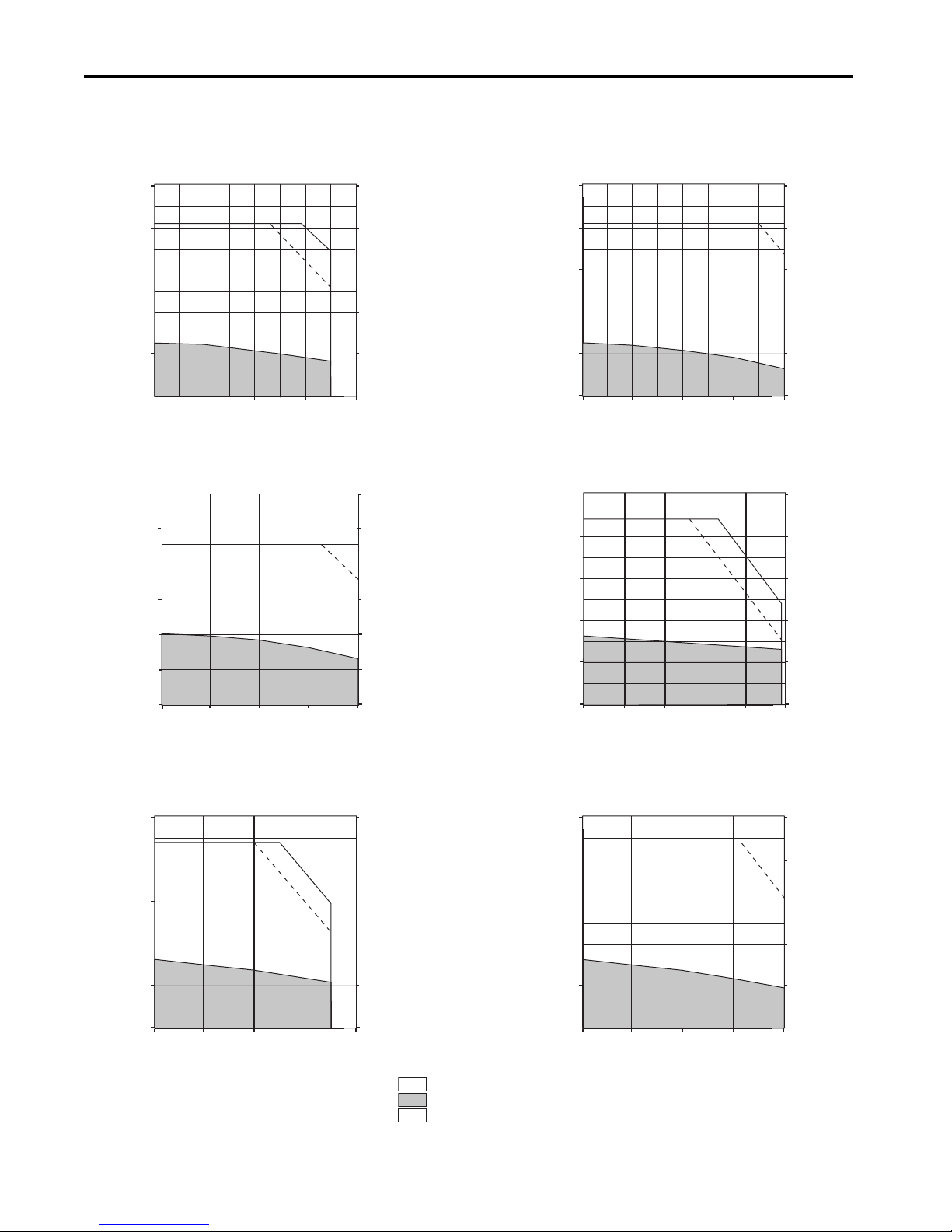
2198-H025-ERSx and VPL-A1001M
35.4
26.5
17.7
8.85
0
4.0
3.0
2.0
1.0
0
0
4000
8000
60002000
Torque
(N•m)
Torque
(lb•in)
Speed (rpm)
2198-H015-ERSx and VPL-A1001C
35.4
26.5
17.7
8.85
0
0
2000
4.0
3.0
2.0
1.0
0
30001000
Torque
(N•m)
Torque
(lb•in)
Speed (rpm)
2198-H040-ERS
x and VPL-A1002F
70.8
53.1
35.4
17.7
0
8.0
6.0
4.0
2.0
0
0
3000
5000
40001000
2000
Torque
(N•m)
Torque
(lb•in)
Speed (rpm)
2198-H025-ERS
x and VPL-A1002C
70.8
53.1
35.4
1.77
0
0
2000
8.0
6.0
4.0
2.0
0
30001000
Torque
(N•m)
Torque
(lb•in)
2198-H040-ERSx and VPL-A1003E
12.0
10.0
8.0
6.0
4.0
2.0
0
Speed (rpm)
106
88.5
70.8
53.1
35.4
17.7
0
0
2000
4000
30001000
Torque
(N•m)
Torque
(lb•in)
2198-H025-ERSx and VPL-A1003C
12.0
10.0
8.0
6.0
4.0
2.0
0
Speed (rpm)
0
1500
2500
2000
500
1000
106
88.5
70.8
53.1
35.4
17.7
0
= Intermittent operating region
= Continuous operating region
= Drive operation with 200V AC rms input voltage
Kinetix 5500 (200V-class operation) Drives/Kinetix VP Low Inertia Motor Curves (continued)
20 Rockwell Automation Publication KNX-RM009C-EN-P - May 2019
Page 21
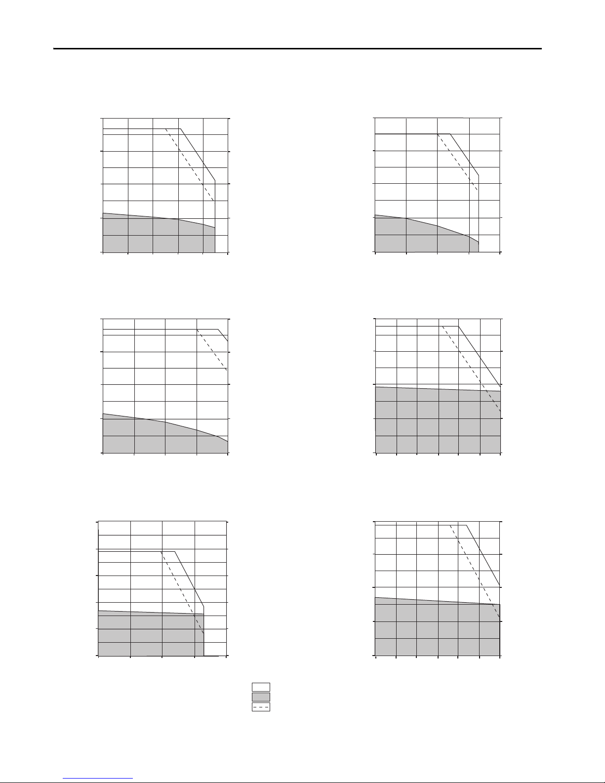
Kinetix 5500 (200V-class operation) Drives/Kinetix VP Low Inertia Motor Curves (continued)
Torque
(N•m)
Torque
(lb•in)
0
0
3.0
6.0
9.0
15.0
12.0
26.5
53.1
79.6
106
133
2198-H025-ERSx and VPL-A1152B
Speed (rpm)
0
1500
2500
2000
500
1000
Torque
(N•m)
Torque
(lb•in)
2198-H070-ERSx and VPL-A1003F
12.0
10.0
8.0
6.0
4.0
2.0
0
Speed (rpm)
106
88.5
70.8
53.1
35.4
17.7
0
0
4000
60002000
Torque
(N•m)
Torque
(lb•in)
0
0
3.0
6.0
9.0
15.0
12.0
26.5
53.1
79.6
106
133
2198-H040-ERSx and VPL-A1152E
Speed (rpm)
0
2000
4000
30001000
Torque
(N•m)
Torque
(lb•in)
0
0
3.0
6.0
9.0
15.0
12.0
26.5
53.1
79.6
106
133
2198-H040-ERSx and VPL-A1152F
Speed (rpm)
0
3000
5000
4000
1000
2000
Torque
(N•m)
Torque
(lb•in)
2198-H040-ERSx and VPL-A1153C
24.0
20.0
16.0
12.0
8.0
4.0
0
Speed (rpm)
212
177
142
106
70.8
35.4
0
0
1500
2500
2000
500
1000
Torque
(N•m)
Torque
(lb•in)
2198-H040-ERSx and VPL-A1303B
24.0
20.0
16.0
12.0
8.0
4.0
0
Speed (rpm)
212
177
142
106
70.8
35.4
0
0
1000
2000
1500500
= Intermittent operating region
= Continuous operating region
= Drive operation with 200V AC rms input voltage
Kinetix 5500 Drive Systems
Rockwell Automation Publication KNX-RM009C-EN-P - May 2019 21
Page 22
Kinetix 5500 Drive Systems
Torque
(N•m)
Torque
(lb•in)
0
0
6.0
12.0
18.0
30.0
24.0
53.1
106
159
212
265
2198-H040-ERSx and VPL-A1304A
Speed (rpm)
0
1000
2000
1500500
Torque
(N•m)
Torque
(lb•in)
2198-H070-ERSx and VPL-A1303F
24.0
20.0
16.0
12.0
8.0
4.0
0
Speed (rpm)
212
177
142
106
70.8
35.4
0
0
2000
4000
30001000
Torque
(N•m)
Torque
(lb•in)
0
0
6.0
12.0
18.0
30.0
24.0
53.1
106
159
212
265
2198-H070-ERSx and VPL-A1304D
Speed (rpm)
0
2000
30001000
Torque
(N•m)
Torque
(lb•in)
Speed (rpm)
500 1000 1500 20000
2198-H070-ERSx and VPL-A1306C
40.0
35.0
30.0
25.0
20.0
15.0
10.0
5.0
0
354
310
265
221
177
133
88.5
44.2
0
= Intermittent operating region
= Continuous operating region
= Drive operation with 200V AC rms input voltage
Kinetix 5500 (200V-class operation) Drives/Kinetix VP Low Inertia Motor Curves (continued)
22 Rockwell Automation Publication KNX-RM009C-EN-P - May 2019
Page 23
Kinetix 5500 Drive Systems
Kinetix 5500 (400V-class operation) Drives with Kinetix VP Low Inertia Motors
This section provides system combination information for the Kinetix 5500 drives (with 400 and 480V, nominal input)
when matched with Kinetix VP (400V-class) low-inertia motors. Single cable catalog numbers, system performance
specifications, and the optimum torque/speed curves are included.
Bulletin VPL Motor Cable Combinations
Rotary Motor (400V-class)
Cat. No.
Single Cable Cat. No.
(1)
Feedback Type
VPL-B063xx
VPL-B0751M, VPL-B0752E, VPL-B0752F, VPL-B0753E, VPL-B0753F
VPL-B1001M, VPL-B1002E,
2090-CSBM1Dx-18AAxx or
2090-CSWM1Dx-18AAxx (standard, non-flex)
2090-CSBM1Dx-18AFxx (continuous-flex)
VPL-B1003C
VPL-B0752M, VPL-B0753M 2090-CSBM1Dx-14AAxx or
VPL-B1002M, VPL-B1003F, VPL-B1003T
VPL-B1152C
2090-CSWM1Dx-14AAxx (standard, non-flex)
2090-CSBM1Dx-14AFxx (continuous-flex)
2090-CSBM1Dx-18AAxx or
2090-CSWM1Dx-18AAxx (standard, non-flex)
Multi-turn or Single-turn
Digital Encoder Feedback
2090-CSBM1Dx-18AFxx (continuous-flex)
VPL-B1152F, VPL-B1152T, VPL-B1153E, VPL-B1153F
VPL-B1303x, VPL-B1304x, VPL-B1306x
VPL-B1651C, VPL-B1651F, VPL-B1652C, VPL-B1652F, VPL-B1653C, VPL-B1653D, VPL-B1654B
2090-CSBM1Dx-14AAxx or
2090-CSWM1Dx-14AAxx (standard, non-flex)
2090-CSBM1Dx-14AFxx (continuous-flex)
VPL-B1654D 2090-CSBM1Dx-10AFxx (continuous-flex)
(1) Use 2090-CSxM1DF or 2090-CSxM1DG cables. Cable length xx is in meters, 01 (3.3)…50 (164) in 1.0 m (3.3 f t) increments. Refer to the Kinetix Motion Accessories Technical Data, publication
KNX-TD004
, for cable specifications. For cable configuration illustrations and feature descriptions, by catalog number, refer to 2090-Series Single Motor Cable Overview beginning on page 13.
Bulletin VPL Motor Performance Specifications with Kinetix 5500 (400V-class operation) Drives
Motor Cat. No.
VPL-B0631T 8000 8000 1.20 0.46 (4.0)
VPL-B0631U 8000 8000 1.92 0.46 (4.0) 6.48 1.33 (12.0) 0.31 (0.42) 2198-H008-ERSx
VPL-B0632F 4600 4600 1.20 0.93 (8.0)
VPL-B0632T 8000 8000 2.55 0.93 (8.0) 8.75 2.69 (24.0) 0.54 (0.72) 2198-H008-ERSx
VPL-B0633M 6500 6700 2.50 1.27 (11.0) 8.75 4.09 (36.0) 0.57 (0.76) 2198-H008-ERSx
VPL-B0633T 6500 8000 3.52 1.27 (11.0)
VPL-B0751M 8000 8000 2.90 1.01 (9.0)
VPL-B0752E 4900 4900 2.70 1.61 (14.0)
VPL-B0752F 7000 7000 3.80 1.61 (14.0) 13.30 4.39 (39.0) 0.80 (1.07) 219 8-H015-ERSx
VPL-B0752M 8000 8000 4.90 1.61 (14.0)
VPL-B0753E 4500 4500 3.80 2.28 (20.0) 13.30 7.35 (65.0) 0.81 (1.09) 2198-H015-ERSx
Rated Speed
rpm
Speed, max
rpm
System Continuous
Stall Current
A (0-pk)
System Continuous
Stall Torque
N•m (lb•in)
System Peak
Stall Current
A 0-pk
3.50 1.12 (10.0)
4.20 1.33 (12.0) 2198-H008-ERSx
3.50 2.26 (20.0)
4.20 2.69 (24.0) 2198-H008-ERSx
8.80 2.87 (25.0)
12.60 4.09 (36.0) 2198-H015-ERSx
8.80 2.20 (19.0)
9.12 2.27 (20.0) 2198-H015-ERSx
8.80 4.10 (36.0)
9.45 4.39 (39.0) 2198-H015-ERSx
17.70 4.10 (36.0)
18.90 4.39 (39.0) 2198-H025-ERSx
System Peak
Stall Torque
N•m (lb•in)
Motor Rated
Output
kW (Hp)
0.31 (0.42)
0.37 (0.50)
0.57 (0.76)
0.54 (0.72)
0.67 (0.90)
0.81 (1.09)
Kinetix 5500 Drives
(480V AC input)
2198-H003-ERSx
2198-H003-ERSx
2198-H008-ERSx
2198-H008-ERSx
2198-H008-ERSx
2198-H015-ERSx
Rockwell Automation Publication KNX-RM009C-EN-P - May 2019 23
Page 24
Kinetix 5500 Drive Systems
Bulletin VPL Motor Performance Specifications with Kinetix 5500 (400V-class operation) Drives (cont.)
Motor Cat. No.
VPL-B0753F 4500 6600 4.09 2.16 (19.0)
VPL-B0753M 6000 8000 6.12 2.28 (20.0)
VPL-B1001M 6000 6000 3.61 1.93 (17.0)
VPL-B1002E 3300 3300 3.44 3.39 (30.0)
VPL-B1002M 6000 6000 6.24 3.39 (30.0)
VPL-B1003C 2500 2500 3.41 4.18 (37.0)
VPL-B1003F 4750 4750 6.14 4.18 (37.0)
VPL-B1003T 7000 7000 9.58 4.18 (37.0)
VPL-B1152C 2250 2250 3.13 5.10 (45.0)
VPL-B1152F 4000 4500 6.17 5.10 (45.0)
VPL-B1152T 6500 6500 10 .81 5.08 (45.0)
VPL-B1153E 3200 3200 6.13 6.55 (58.0)
VPL-B1153F 5000 5000 8.88 6.55 (58.0)
VPL-B1303C 2250 2250 6.30 8.80 (78.0)
VPL-B1303F 4000 4000 10.10 8.80 (78.0)
VPL-B1304C 2150 2150 7.0 10.29 (91.0)
VPL-B1304E 3500 3500 9.44 10.29 (91.0)
VPL-B1306C 2500 250 0 10.80 13.38 (118)
VPL-B1306F 4250 4250 14.78 13.38 (118)
VPL-B1651C 2750 275 0 10.21 11.50 (102)
VPL-B1651F 4750 4750 17.60 11.43 (101)
Rated Speed
rpm
Speed, max
rpm
System Continuous
Stall Current
A (0-pk)
System Continuous
Stall Torque
N•m (lb•in)
System Peak
Stall Current
A 0-pk
17.70 6.55 (58.0)
18.90 7.02 (62.0) 2198-H025-ERSx
17.70 5.13 (45.0)
25.34 7.35 (65.0) 2198-H025-ERSx
8.80 3.22 (28.0)
10.38 3.78 (33.0) 2198-H015-ERSx
8.80 6.47 (57.0)
10.69 7.82 (69.0) 2198-H015-ERSx
17.70 6.80 (60.0)
20.33 7.82 (69.0) 2198-H025-ERSx
8.80 9.29 (82.0)
10.61 11.15 (99.0) 2198-H015-ERSx
17.70 9.76 (86.0)
20.20 11.15 (99.0) 2198-H025-ERSx
28.30 9.76 (86.0)
28.80 11.15 (99.0) 2198-H040-ERSx
8.80 10.80 (95.0)
10.74 13.12 (116) 2198-H015-ERSx
17.70 10.95 (97.0)
21.19 13.12 (116) 2198-H025-ERSx
28.30 12.14 (107)
32.10 13.12 (116) 2198-H040-ERSx
17.70 16.85 (149)
21.33 20.33 (180) 2198-H025-ERSx
28.30 18.30 (162)
33.0 20.33 (180) 2198-H040-ERSx
17.70 19.83 (175)
18.47 20.72 (183) 2198-H025-ER Sx
28.30 19.85 (175)
31.0 20.72 (183) 2198-H040-ERSx
17.70 22.55 (199)
22.3 28.45 (252) 2198-H025-ERSx
28.30 25.03 (221)
33.76 28.45 (252) 2198-H040-ER Sx
28.30 31.21 (276)
32.94 34.62 (306) 2198-H040-ER Sx
45.90 28.50 (252)
55.83 34.62 (306) 2198-H070-ER Sx
28.30 21.68 (192)
29.29 22.45 (199) 2198-H040-ER Sx
45.90 18.02 (159)
57.27 22.45 (199) 2198-H070-ER Sx
System Peak
Stall Torque
N•m (lb•in)
Motor Rated
Output
kW (Hp)
0.65 (0.87)
0.82 (1.10)
1.14 (1.53)
1.12 (1.50)
1.86 (2.49)
0.96 (1.29)
1.65 (2.21)
1.77 (2.37)
1.06 (1.42)
1.40 (1.88)
2.29 (3.07)
1.75 (2.35)
2.30 (3.08)
1.83 (2.45)
2.82 (3.78)
1.75 (2.35)
2.82 (3.78)
2.46 (3.30)
2.95 (3.95)
2.32 (3.11)
4.38 (5.87)
Kinetix 5500 Drives
(480V AC input)
2198-H015-ERSx
2198-H015-ERSx
2198-H008-ERSx
2198-H008-ERSx
2198-H015-ERSx
2198-H008-ERSx
2198-H015-ERSx
2198-H025-ERSx
2198-H008-ERSx
2198-H015-ERSx
2198-H025-ERSx
2198-H015-ERSx
2198-H025-ERSx
2198-H015-ERSx
2198-H025-ERSx
2198-H015-ERSx
2198-H025-ERSx
2198-H025-ERSx
2198-H040-ERSx
2198-H025-ERSx
2198-H040-ERSx
24 Rockwell Automation Publication KNX-RM009C-EN-P - May 2019
Page 25
Kinetix 5500 Drive Systems
Torque
(N•m)
Torque
(lb•in)
Speed (rpm)
2198-H008-ERSx and VPL-B0631T
2.0
1.5
1.0
0.5
0
0
4000
8000
60002000
17.7
13.3
8.85
4.42
0
Torque
(N•m)
Torque
(lb•in)
Speed (rpm)
2198-H008-ERSx and VPL-B0631U
2.0
1.5
1.0
0.5
0
0
4000
8000
60002000
17.7
13.3
8.85
4.42
0
Peak curve represents
480V and 400V inputs
Torque
(N•m)
Torque
(lb•in)
2198-H008-ERSx and VPL-B0632F
3.0
2.5
2.0
1.5
1.0
0.5
0
Speed (rpm)
0
3000
5000
4000
1000
2000
26.5
22.1
17.7
13.3
8.85
4.42
0
Torque
(N•m)
Torque
(lb•in)
2198-H008-ERSx and VPL-B0632T
3.0
2.5
2.0
1.5
1.0
0.5
0
26.5
22.1
17.7
13.3
8.85
4.42
0
Speed (rpm)
0
4000
8000
60002000
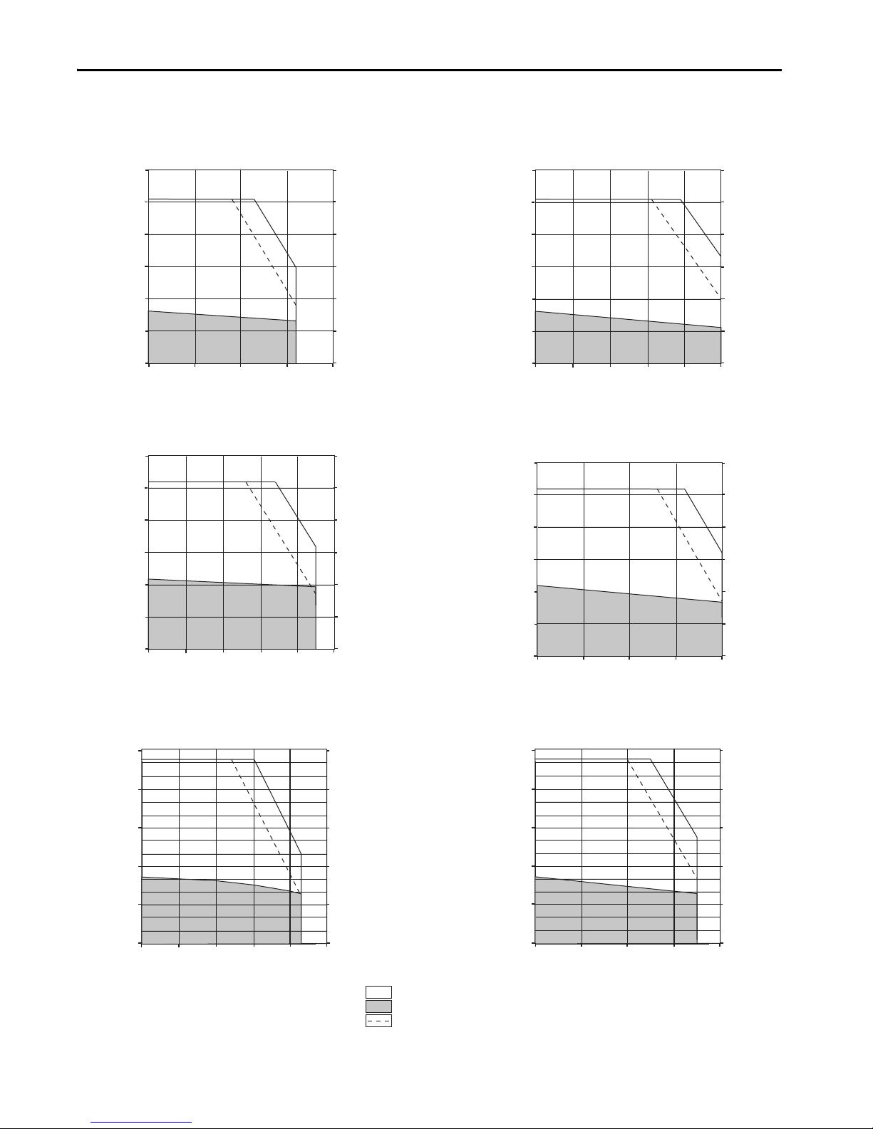
= Intermittent operating region
= Continuous operating region
= Drive operation with 400V AC rms input voltage
Bulletin VPL Motor Performance Specifications with Kinetix 5500 (400V-class operation) Drives (cont.)
Motor Cat. No.
VPL-B1652C 2700 270 0 16.0 19.40 (172)
VPL-B1652F 4000 4000 18.60 17.60 (156) 60.00 48.60 (430) 4.77 (6.40) 2198-H070-ERSx
VPL-B1653C 2300 230 0 17.75 25.76 (228)
VPL-B1653D 3000 3000 18.60 24.20 (214) 68.00 67.80 (600) 5.50 (7.30) 2198-H070-ERSx
VPL-B1654B 1850 1850 15.54 32.97 (292)
VPL-B1654D 3000 3000 24.47 32.0 (283) 81.30 75.30 (666) 7.16 (9.60) 2198-H070-ERSx
Performance specification data and curves reflect nominal sys tem performance of a typical system with the motor at 40 °C (104 °F) and the drive at 50 °C (122 °F) ambient, and rated line voltage. For
additional information on ambient and line conditions, refer to Motion Analyzer software.
Rated Speed
rpm
Speed, max
rpm
System Continuous
Stall Current
A (0-pk)
System Continuous
Stall Torque
N•m (lb•in)
System Peak
Stall Current
A 0-pk
45.90 44.78 (396)
49.88 48.60 (430) 2198-H070-ER Sx
45.90 55.14 (488)
55.60 66.70 (590) 2198-H070-ER Sx
45.90 65.38 (578)
55.75 79.30 (702) 2198-H070-ER Sx
System Peak
Stall Torque
N•m (lb•in)
Motor Rated
Output
kW (Hp)
4.18 (5.60)
4.38 (5.87)
5.55 (7.44)
Kinetix 5500 Drives
(480V AC input)
2198-H040-ERSx
2198-H040-ERSx
2198-H040-ERSx
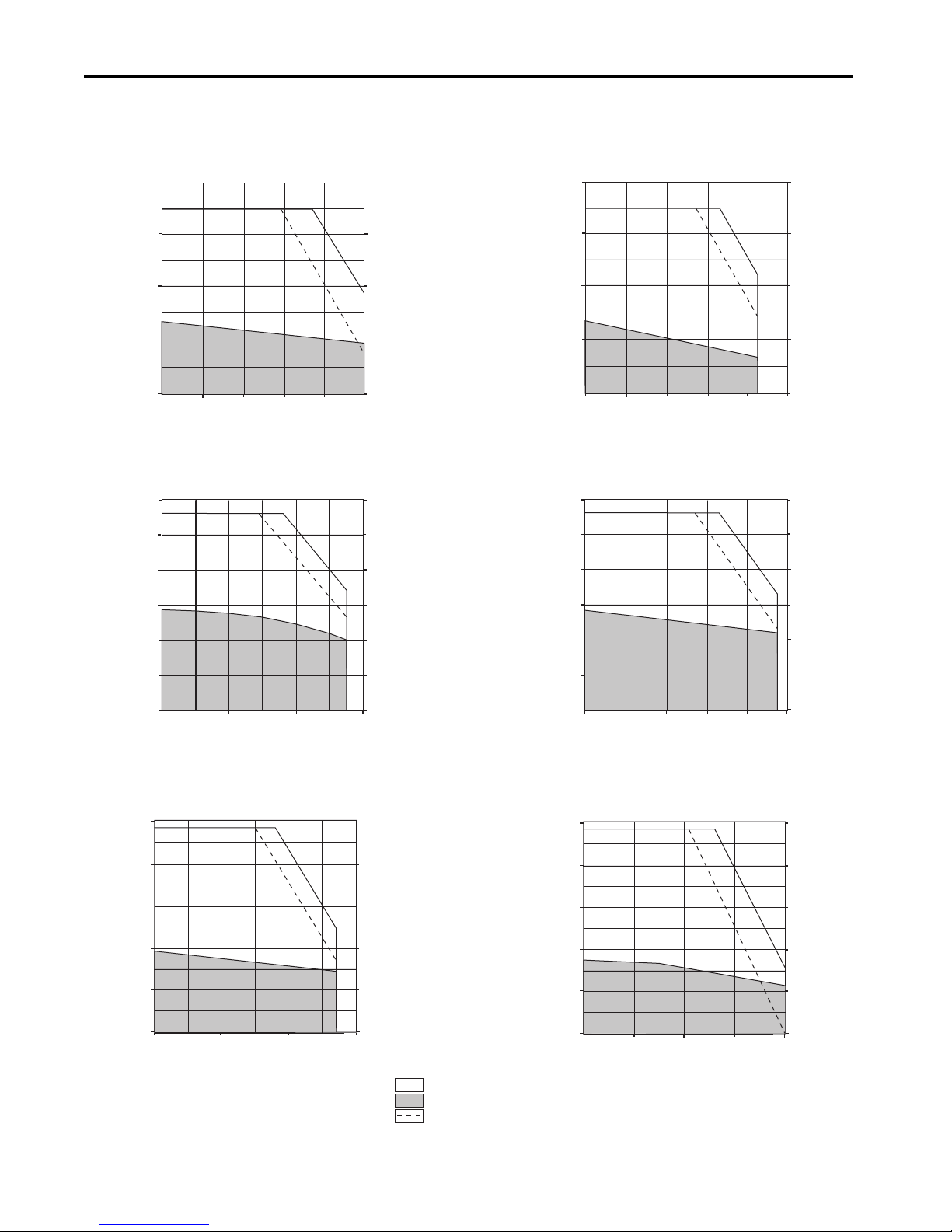
Kinetix 5500 (400V-class operation) Drives/Kinetix VP Low Inertia Motor Curves
Rockwell Automation Publication KNX-RM009C-EN-P - May 2019 25
Page 26
Kinetix 5500 Drive Systems
Torque
(N•m)
Torque
(lb•in)
0
0
1.0
2.0
3.0
5.0
4.0
8.85
17.7
26.5
35.4
44.2
2198-H008-ERSx and VPL-B0633M
Speed (rpm)
0
4000
8000
60002000
Torque
(N•m)
Torque
(lb•in)
0
0
1.0
2.0
3.0
5.0
4.0
8.85
17.7
26.5
35.4
44.2
2198-H015-ERSx and VPL-B0633T
Speed (rpm)
0
4000
8000
60002000
Torque
(N•m)
Torque
(lb•in)
2198-H015-ERS
x and VPL-B0751M
3.0
2.5
2.0
1.5
1.0
0.5
0
26.5
22.1
17.7
13.3
8.85
4.42
0
Speed (rpm)
0
4000
8000
60002000
Torque
(N•m)
Torque
(lb•in)
0
0
1.0
2.0
3.0
5.0
4.0
8.85
17.7
26.5
35.4
44.2
2198-H015-ERS
x and VPL-B0752E
Speed (rpm)
0
3000
5000
4000
1000
2000
= Intermittent operating region
= Continuous operating region
= Drive operation with 400V AC rms input voltage
Torque
(N•m)
Torque
(lb•in)
0
0
1.0
2.0
3.0
5.0
4.0
8.85
17.7
26.5
35.4
44.2
2198-H015-ERSx and VPL-B0752F
Speed (rpm)
0
4000
8000
60002000
Torque
(N•m)
Torque
(lb•in)
0
0
1.0
2.0
3.0
5.0
4.0
8.85
17.7
26.5
35.4
44.2
2198-H025-ERSx and VPL-B0752M
Speed (rpm)
0
4000
8000
60002000
Kinetix 5500 (400V-class operation) Drives/Kinetix VP Low Inertia Motor Curves (continued)
26 Rockwell Automation Publication KNX-RM009C-EN-P - May 2019
Page 27
Kinetix 5500 (400V-class operation) Drives/Kinetix VP Low Inertia Motor Curves (continued)
Torque
(N•m)
Torque
(lb•in)
Speed (rpm)
2198-H015-ERSx and VPL-B0753E
70.8
53.1
35.4
17.7
0
8.0
6.0
4.0
2.0
0
0
3000
5000
40001000
2000
Torque
(N•m)
Torque
(lb•in)
2198-H025-ERS
x and VPL-B0753F
70.8
53.1
35.4
1.77
0
8.0
6.0
4.0
2.0
0
Speed (rpm)
0
4000
8000
60002000
Torque
(N•m)
Torque
(lb•in)
Speed (rpm)
2198-H015-ERSx and VPL-B1001M
35.4
26.5
17.7
8.85
0
0
2000
4.0
3.0
2.0
1.0
0
30001000 6000
5000
4000
Torque
(N•m)
Torque
(lb•in)
2198-H025-ERSx and VPL-B0753M
70.8
53.1
35.4
17.7
0
8.0
6.0
4.0
2.0
0
Speed (rpm)
0
4000
8000
60002000
Torque
(N•m)
Torque
(lb•in)
Speed (rpm)
2198-H025-ERSx and VPL-B1002M
70.8
53.1
35.4
17.7
0
0
2000
8.0
6.0
4.0
2.0
0
30001000 6000
5000
4000
Torque
(N•m)
Torque
(lb•in)
0
0
2.0
4.0
6.0
10.0
8.0
17.7
35.4
53.1
70.8
88.5
2198-H015-ERSx and VPL-B1002E
Speed (rpm)
0
2000
4000
30001000
= Intermittent operating region
= Continuous operating region
= Drive operation with 400V AC rms input voltage
Kinetix 5500 Drive Systems
Rockwell Automation Publication KNX-RM009C-EN-P - May 2019 27
Page 28
Kinetix 5500 Drive Systems
Torque
(N•m)
Torque
(lb•in)
2198-H015-ERSx and VPL-B1003C
12.0
10.0
8.0
6.0
4.0
2.0
0
Speed (rpm)
106
88.5
70.8
53.1
35.4
17.7
0
0
1500
2500
2000
500
1000
Torque
(N•m)
Torque
(lb•in)
2198-H025-ERSx and VPL-B1003F
12.0
10.0
8.0
6.0
4.0
2.0
0
Speed (rpm)
106
88.5
70.8
53.1
35.4
17.7
0
0
3000
5000
4000
1000
2000
Torque
(N•m)
Torque
(lb•in)
Speed (rpm)
2198-H040-ERSx and VPL-B1003T
0
4000
8000
60002000
12.0
10.0
8.0
6.0
4.0
2.0
0
106
88.5
70.8
53.1
35.4
17.7
0
Torque
(N•m)
Torque
(lb•in)
0
0
3.0
6.0
9.0
15.0
12.0
26.5
53.1
79.6
106
133
2198-H015-ERSx and VPL-B1152C
Speed (rpm)
0
1500
2500
2000
500
1000
Torque
(N•m)
Torque
(lb•in)
0
0
3.0
6.0
9.0
15.0
12.0
26.5
53.1
79.6
106
133
2198-H025-ERSx and VPL-B1152F
Speed (rpm)
0
3000
5000
4000
1000
2000
Torque
(N•m)
Torque
(lb•in)
0
0
3.0
6.0
9.0
15.0
12.0
26.5
53.1
79.6
106
133
2198-H040-ERSx and VPL-B1152T
Speed (rpm)
0
4000
8000
60002000
= Intermittent operating region
= Continuous operating region
= Drive operation with 400V AC rms input voltage
Kinetix 5500 (400V-class operation) Drives/Kinetix VP Low Inertia Motor Curves (continued)
28 Rockwell Automation Publication KNX-RM009C-EN-P - May 2019
Page 29
Kinetix 5500 (400V-class operation) Drives/Kinetix VP Low Inertia Motor Curves (continued)
Torque
(N•m)
Torque
(lb•in)
2198-H025-ERSx and VPL-B1153E
24.0
20.0
16.0
12.0
8.0
4.0
0
Speed (rpm)
212
177
142
106
70.8
35.4
0
0
2000
4000
30001000
Torque
(N•m)
Torque
(lb•in)
2198-H040-ERSx and VPL-B1153F
24.0
20.0
16.0
12.0
8.0
4.0
0
Speed (rpm)
212
177
142
106
70.8
35.4
0
0
3000
5000
4000
1000
2000
Torque
(N•m)
Torque
(lb•in)
2198-H025-ERSx and VPL-B1303C
24.0
20.0
16.0
12.0
8.0
4.0
0
Speed (rpm)
212
177
142
106
70.8
35.4
0
0
1500
2500
2000
500
1000
Torque
(N•m)
Torque
(lb•in)
2198-H040-ERS
x and VPL-B1303F
24.0
20.0
16.0
12.0
8.0
4.0
0
Speed (rpm)
212
177
142
106
70.8
35.4
0
0
2000
4000
30001000
Torque
(N•m)
Torque
(lb•in)
0
0
6.0
12.0
18.0
30.0
24.0
53.1
106
159
212
265
2198-H025-ERS
x and VPL-B1304C
Speed (rpm)
0
1500
2500
2000
500
1000
Torque
(N•m)
Torque
(lb•in)
0
0
6.0
12.0
18.0
30.0
24.0
53.1
106
159
212
265
2198-H040-ERSx and VPL-B1304E
0
2000
4000
30001000
Speed (rpm)
= Intermittent operating region
= Continuous operating region
= Drive operation with 400V AC rms input voltage
Kinetix 5500 Drive Systems
Rockwell Automation Publication KNX-RM009C-EN-P - May 2019 29
Page 30
Kinetix 5500 Drive Systems
Torque
(N•m)
Torque
(lb•in)
Speed (rpm)
2198-H040-ERSx and VPL-B1306C
354
265
177
88.5
0
40.0
30.0
20.0
10.0
0
0
1500
2500
2000
500
1000
Torque
(N•m)
Torque
(lb•in)
Speed (rpm)
2198-H070-ERSx and VPL-B1306F
354
265
177
88.5
0
40.0
30.0
20.0
10.0
0
0
3000
5000
4000
1000
2000
Torque
(N•m)
Torque
(lb•in)
2198-H040-ERSx and VPL-B1651C
24.0
20.0
16.0
12.0
8.0
4.0
0
Speed (rpm)
212
177
142
106
70.8
35.4
0
0
2000
30001000
Torque
(N•m)
Torque
(lb•in)
2198-H070-ERSx and VPL-B1651F
24.0
20.0
16.0
12.0
8.0
4.0
0
Speed (rpm)
212
177
142
106
70.8
35.4
0
0
3000
5000
4000
1000
2000
Torque
(N•m)
Torque
(lb•in)
0
0
10.0
20.0
30.0
50.0
40.0
88.5
177
265
354
442
2198-H070-ERSx and VPL-B1652C
Speed (rpm)
0
2000
30001000
Torque
(N•m)
Torque
(lb•in)
0
0
10.0
20.0
30.0
50.0
40.0
88.5
177
265
354
442
2198-H070-ERSx and VPL-B1652F
Speed (rpm)
0
2000
4000
30001000
= Intermittent operating region
= Continuous operating region
= Drive operation with 400V AC rms input voltage
Kinetix 5500 (400V-class operation) Drives/Kinetix VP Low Inertia Motor Curves (continued)
30 Rockwell Automation Publication KNX-RM009C-EN-P - May 2019
Page 31

Kinetix 5500 (400V-class operation) Drives/Kinetix VP Low Inertia Motor Curves (continued)
Torque
(N•m)
Torque
(lb•in)
Speed (rpm)
2198-H070-ERSx and VPL-B1653C
708
531
354
177
0
80.0
60.0
40.0
20.0
0
0
1500
2500
2000
500
1000
Torque
(N•m)
Torque
(lb•in)
Speed (rpm)
2198-H070-ERSx and VPL-B1653D
708
531
354
177
0
0
1000
80.0
60.0
40.0
20.0
0
1500500 3000
2500
2000
Torque
(N•m)
Torque
(lb•in)
Speed (rpm)
2198-H070-ERSx and VPL-B1654B
708
531
354
177
0
80.0
60.0
40.0
20.0
0
0
1000
2000
1500500
Torque
(N•m)
Torque
(lb•in)
Speed (rpm)
2198-H070-ERSx and VPL-B1654D
708
531
354
177
0
0
1000
80.0
60.0
40.0
20.0
0
1500500 3000
2500
2000
= Intermittent operating region
= Continuous operating region
= Drive operation with 400V AC rms input voltage
Kinetix 5500 Drive Systems
Rockwell Automation Publication KNX-RM009C-EN-P - May 2019 31
Page 32

Kinetix 5500 Drive Systems
Kinetix 5500 (200V-class operation) Drives with Kinetix VP Food Grade Motors
This section provides system combination information for the Kinetix 5500 drives (with 200 and 240V, nominal input)
when matched with Kinetix VP (200V-class) food-grade motors. Single cable catalog numbers, system performance
specifications, and the optimum torque/speed curves are included.
Kinetix 5500 servo drives are capable of 200V or 400V-class operation. These system performance tables and torque/
speed curves reflect single-phase and three-phase drive operation with 200V-class motors; however, only
2198-H003-ERSx, 2198-H008-ERSx, and 2198-H015-ERSx drives are capable of single-phase operation.
Bulletin VPF Motor Cable Combinations
Rotary Motor (200V-class)
Cat. No.
VPF-A0632F, VPF-A0633C, VPF-A0633F
VPF-A0752C, VPF-A0753C
VPF-A1001C
VPF-A0752E, VPF-A0753E
VPF-A1001M, VPF-A1002C, VPF-A1002F
VPF-A1003C, VPF-A1003E, VPF-A1003F
VPF-A1153C
VPF-A1303B, VPF-A1303F
VPF-A1304A, VPF-A1304D
(1) Use 2090-CSxM1DF or 2090-CSxM1DG cables. Cable length xx is in meters, 01 (3.3)…50 (164) in 1.0 m (3.3 f t) increments. Refer to the Kinetix Motion Accessories Technical Data, publication
KNX-TD004
, for cable specifications. For cable configuration illustrations and feature descriptions, by catalog number, refer to 2090-Series Single Motor Cable Overview beginning on page 13.
Single Cable Cat. No.
2090-CSBM1Dx-18AAxx or
2090-CSWM1Dx-18AAxx (standard, non-flex)
2090-CSBM1Dx-18AFxx (continuous-flex)
2090-CSBM1Dx-14AAxx or
2090-CSWM1Dx-14AAxx (standard, non-flex)
2090-CSBM1Dx-14AFxx (continuous-flex)
(1)
Feedback Type
Multi-turn or Single-turn
Digital Encoder Feedback
32 Rockwell Automation Publication KNX-RM009C-EN-P - May 2019
Page 33

Bulletin VPF Motor Performance Specifications with Kinetix 5500 (200V-class operation) Drives
Kinetix 5500 Drive Systems
Rotary Motor
Cat. No.
VPF-A0632F 4800 4800 2.55 0.93 (8.0) 8.75 2.69 (24.0) 0.36 (0.48 ) 2198-H0 08-ERSx
VPF-A0633C 3000 3000 2.50 1.27 (11.0) 8.75 4.09 (36.0) 0.37 (0.50) 2198-H008-ERSx
VPF-A0633F 4500 4500 3.52 1.27 (11.0)
VPF-A0752C 3300 3300 3.80 1.61 (14.0) 13.30 4.39 (39.0) 0.49 (0.66) 2198-H015-ERSx
VPF-A0752E 4800 4800 4.90 1.61 (14.0)
VPF-A0753C 3300 3300 4.09 2.16 (19.0)
VPF-A0753E 4600 4600 6.12 2.28 (20.0)
VPF-A1001C 2800 2800 3.61 1.93 (17.0)
VPF-A1001M 6500 6500 7.15 1.95 (17.0)
VPF-A1002C 3000 3000 6.24 3.39 (30.0)
VPF-A1002F 5000 5000 10.04 3.26 (29.0)
VPF-A1003C 2250 2250 6.14 4.18 (37.0)
VPF-A1003E 3750 3750 9.58 4.18 (37.0)
VPF-A1003F 5500 5500 15.62 4.18 (37.0)
VPF-A1153C 2300 2300 8.88 6.50 (58.0)
VPF-A1303B 1950 1950 10.34 8.80 (78.0)
VPF-A1303F 4000 4000 18.60 7.75 (69.0)
VPF-A1304A 1600 1600 9.43 10 .29 (91.0)
VPF-A1304D 3000 3000 18.40 10.20 (90.0)
Performance specification data and curves reflect nominal sys tem performance of a typical system with the motor at 40 °C (104 °F) and the drive at 50 °C (122 °F) ambient, and rated line voltage. For
additional information on ambient and line conditions, refer to Motion Analyzer software.
Rated Speed
rpm
Speed, max
rpm
System Continuous
Stall Current
A 0-pk
System Continuous
Stall Torque
N•m (lb•in)
System Peak
Stall Current
A 0-pk
8.80 2.87 (25.0)
12.60 4.09 (36.0) 2198-H015-ERSx
17.70 4.10 (36.0)
18.90 4.39 (39.0) 2198-H025-ERSx
17.70 6.55 (58.0)
18.90 7.02 (62.0) 2198-H025-ERSx
17.70 5.13 (45.0)
25.34 7.35 (65.0) 2198-H025-ERSx
8.80 3.22 (28.0)
10.38 3.78 (33.0) 2198-H015-ERSx
17.70 3.31 (29.0)
20.20 3.78 (33.0) 2198-H025-ERSx
17.70 6.80 (60.0)
20.33 7.82 (69.0) 2198-H025-ERSx
28.30 6.77 (60.0)
34.30 7.82 (69.0) 2198-H040-ERSx
17.70 9.76 (86.0)
20.20 11.15 (99.0) 2198-H025-ERSx
28.30 9.76 (86.0)
28.80 11.15 (99.0) 2198-H040-ERSx
45.90 10.25 (90.0)
50.0 11.15 (99.0) 2198-H070-ERSx
28.30 18.30 (162)
33.0 20.33 (180) 2198-H040-ERSx
28.30 19.85 (175)
31.0 20.72 (183) 2198-H040-ERSx
45.90 15.36 (136)
62.0 20.72 (183) 2198-H070-ERSx
28.30 25.03 (221)
33.76 28.45 (252) 2198-H040-ERSx
45.90 21.48 (190)
58.0 27.10 (240) 2198-H070-ERSx
System Peak
Stall Torque
N•m (lb•in)
Motor Rated
Output
kW (Hp)
0.47 (0.63)
0.63 (0.84)
0.59 (0.79)
0.76 (1.02)
0.56 (0.75)
1.29 (1.73)
1.03 (1.38)
1.60 (2.14)
0.83 (1.11)
1.25 (1.67)
1.81 (2.42)
1.16 (1.56)
1.53 (2.05)
2.25 (3.02)
1.47 (1.98)
1.98 (2.65)
Kinetix 5500 Drives
(240V AC Input)
2198-H008-ERSx
2198-H015-ERSx
2198-H015-ERSx
2198-H015-ERSx
2198-H008-ERSx
2198-H015-ERSx
2198-H015-ERSx
2198-H025-ERSx
2198-H015-ERSx
2198-H025-ERSx
2198-H040-ERSx
2198-H025-ERSx
2198-H025-ERSx
2198-H040-ERSx
2198-H025-ERSx
2198-H040-ERSx
Rockwell Automation Publication KNX-RM009C-EN-P - May 2019 33
Page 34

Kinetix 5500 Drive Systems
Torque
(N•m)
Torque
(lb•in)
2198-H008-ERSx and VPF-A0632F
3.0
2.5
2.0
1.5
1.0
0.5
0
Speed (rpm)
0
3000
5000
4000
1000
2000
26.5
22.1
17.7
13.3
8.85
4.42
0
Torque
(N•m)
Torque
(lb•in)
0
0
1.0
2.0
3.0
5.0
4.0
8.85
17.7
26.5
35.4
44.2
2198-H008-ERS
x and VPF-A0633C
Speed (rpm)
0
2000
30001000
Torque
(N•m)
Torque
(lb•in)
0
0
1.0
2.0
3.0
5.0
4.0
8.85
17.7
26.5
35.4
44.2
2198-H015-ERS
x and VPF-A0633F
Speed (rpm)
0
3000
5000
4000
1000
2000
Torque
(N•m)
Torque
(lb•in)
0
0
1.0
2.0
3.0
5.0
4.0
8.85
17.7
26.5
35.4
44.2
2198-H015-ERS
x and VPF-A0752C
Speed (rpm)
0
2000
4000
30001000
Torque
(N•m)
Torque
(lb•in)
0
0
1.0
2.0
3.0
5.0
4.0
8.85
17.7
26.5
35.4
44.2
2198-H025-ERSx and VPF-A0752E
Speed (rpm)
0
3000
5000
4000
1000
2000
Torque
(N•m)
Torque
(lb•in)
2198-H025-ERSx and VPF-A0753C
70.8
53.1
35.4
1.77
0
8.0
6.0
4.0
2.0
0
Speed (rpm)
0
2000
4000
30001000
= Intermittent operating region
= Continuous operating region
= Drive operation with 200V AC rms input voltage
Kinetix 5500 (200V-class operation) Drives/Kinetix VP Food Grade Motor Curves
34 Rockwell Automation Publication KNX-RM009C-EN-P - May 2019
Page 35

Kinetix 5500 (200V-class operation) Drives/Kinetix VP Food Grade Motor Curves (continued)
Torque
(N•m)
Torque
(lb•in)
Speed (rpm)
2198-H025-ERSx and VPF-A0753E
70.8
53.1
35.4
17.7
0
8.0
6.0
4.0
2.0
0
0
3000
5000
40001000
2000
Torque
(N•m)
Torque
(lb•in)
Speed (rpm)
2198-H015-ERS
x and VPF-A1001C
35.4
26.5
17.7
8.85
0
0
2000
4.0
3.0
2.0
1.0
0
30001000
Torque
(N•m)
Torque
(lb•in)
Speed (rpm)
2198-H025-ERSx and VPF-A1001M
35.4
26.5
17.7
8.85
0
4.0
3.0
2.0
1.0
0
0
4000
8000
60002000
Torque
(N•m)
Torque
(lb•in)
Speed (rpm)
2198-H025-ERSx and VPF-A1002C
70.8
53.1
35.4
1.77
0
0
2000
8.0
6.0
4.0
2.0
0
30001000
Torque
(N•m)
Torque
(lb•in)
Speed (rpm)
2198-H040-ERSx and VPF-A1002F
70.8
53.1
35.4
17.7
0
8.0
6.0
4.0
2.0
0
0
3000
5000
40001000
2000
Torque
(N•m)
Torque
(lb•in)
2198-H025-ERSx and VPF-A1003C
12.0
10.0
8.0
6.0
4.0
2.0
0
Speed (rpm)
0
1500
2500
2000
500
1000
106
88.5
70.8
53.1
35.4
17.7
0
= Intermittent operating region
= Continuous operating region
= Drive operation with 200V AC rms input voltage
Kinetix 5500 Drive Systems
Rockwell Automation Publication KNX-RM009C-EN-P - May 2019 35
Page 36

Kinetix 5500 Drive Systems
Torque
(N•m)
Torque
(lb•in)
2198-H040-ERSx and VPF-A1003E
12.0
10.0
8.0
6.0
4.0
2.0
0
Speed (rpm)
106
88.5
70.8
53.1
35.4
17.7
0
0
2000
4000
30001000
Torque
(N•m)
Torque
(lb•in)
2198-H070-ERSx and VPF-A1003F
12.0
10.0
8.0
6.0
4.0
2.0
0
Speed (rpm)
106
88.5
70.8
53.1
35.4
17.7
0
0
4000
60002000
Torque
(N•m)
Torque
(lb•in)
2198-H040-ERSx and VPF-A1153C
24.0
20.0
16.0
12.0
8.0
4.0
0
Speed (rpm)
212
177
142
106
70.8
35.4
0
0
1500
2500
2000
500
1000
Torque
(N•m)
Torque
(lb•in)
2198-H040-ERSx and VPF-A1303B
24.0
20.0
16.0
12.0
8.0
4.0
0
Speed (rpm)
212
177
142
106
70.8
35.4
0
0
1000
2000
1500500
Torque
(N•m)
Torque
(lb•in)
2198-H070-ERSx and VPF-A1303F
24.0
20.0
16.0
12.0
8.0
4.0
0
Speed (rpm)
212
177
142
106
70.8
35.4
0
0
2000
4000
30001000
Torque
(N•m)
Torque
(lb•in)
0
0
6.0
12.0
18.0
30.0
24.0
53.1
106
159
212
265
2198-H040-ERSx and VPF-A1304A
Speed (rpm)
0
1000
2000
1500500
= Intermittent operating region
= Continuous operating region
= Drive operation with 200V AC rms input voltage
Kinetix 5500 (200V-class operation) Drives/Kinetix VP Food Grade Motor Curves (continued)
36 Rockwell Automation Publication KNX-RM009C-EN-P - May 2019
Page 37

Kinetix 5500 Drive Systems
Torque
(N•m)
Torque
(lb•in)
0
0
6.0
12.0
18.0
30.0
24.0
53.1
106
159
212
265
2198-H070-ERSx and VPF-A1304D
Speed (rpm)
0
2000
30001000
= Intermittent operating region
= Continuous operating region
= Drive operation with 200V AC rms input voltage
Kinetix 5500 (200V-class operation) Drives/Kinetix VP Food Grade Motor Curves (continued)
Kinetix 5500 (400V-class operation) Drives with Kinetix VP Food Grade Motors
This section provides system combination information for the Kinetix 5500 drives (with 400 and 480V, nominal input)
when matched with Kinetix VP (400V-class) food-grade motors. Single cable catalog numbers, system performance
specifications, and the optimum torque/speed curves are included.
Bulletin VPF Motor Cable Combinations
Rotary Motor (400V-class)
Cat. No.
VPF-B0632F, VPF-B0632T, VPF-B0633M, VPF-B0633T
VPF-B0752E, VPF-B0752F, VPF-B0753E, VPF-B0753F
VPF-B1001M, VPF-B1002E, VPF-B1003C
Single Cable Cat. No.
2090-CSBM1Dx-18AAxx or
2090-CSWM1Dx-18AAxx (standard, non-flex)
2090-CSBM1Dx-18AFxx (continuous-flex)
VPF-B0752M, VPF-B0753M
VPF-B1002M, VPF-B1003F, VPF-B1003T
VPF-B1153E, VPF-B1153F
VPF-B1303C, VPF-B1303F, VPF-B1304C, VPF-B1304E
2090-CSBM1Dx-14AAxx or
2090-CSWM1Dx-14AAxx (standard, non-flex)
2090-CSBM1Dx-14AFxx (continuous-flex)
VPF-B1652C
(1) Use 2090-CSxM1DF or 2090-CSxM1DG cables. Cable length xx is in meters, 01 (3.3)…50 (164) in 1.0 m (3.3 f t) increments. Refer to the Kinetix Motion Accessories Technical Data, publication
KNX-TD004
, for cable specifications. For cable configuration illustrations and feature descriptions, by catalog number, refer to 2090-Series Single Motor Cable Overview beginning on page 13.
Bulletin VPF Motor Performance Specifications with Kinetix 5500 (400V-class operation) Drives
Motor Cat. No.
VPF-B0632F 4600 4600 1.20 0.93 (8.0)
VPF-B0632T 8000 8000 2.55 0.93 (8.0) 8.75 2.69 (24.0) 0.41 (0.55) 2198-H008-ERS x
VPF-B0633M 6700 6700 2.50 1.27 (11.0) 8.75 4.09 (36.0) 0.49 (0.66) 2198-H008-ERSx
Rated Speed
rpm
Speed, max
rpm
System Continuous
Stall Current
A (0-pk)
System Continuous
Stall Torque
N•m (lb•in)
System Peak
Stall Current
A 0-pk
3.50 2.26 (20.0)
4.20 2.69 (24.0) 2198-H008-ERSx
(1)
System Peak
Stall Torque
N•m (lb•in)
Feedback Type
Multi-turn or Single-turn
Digital Encoder Feedback
Motor Rated
Output
kW (Hp)
0.34 (0.46)
Kinetix 5500 Drives
(480V AC input)
2198-H003-ERSx
Rockwell Automation Publication KNX-RM009C-EN-P - May 2019 37
Page 38

Kinetix 5500 Drive Systems
Bulletin VPF Motor Performance Specifications with Kinetix 5500 (400V-class operation) Drives (cont.)
Motor Cat. No.
VPF-B0633T 8000 8000 3.52 1.27 (11.0)
VPF-B0752E 4900 4900 2.70 1.61 (14.0)
VPF-B0752F 7000 7000 3.80 1.61 (14.0) 13.30 4.39 (39.0) 0.76 (1.02) 2198-H015-ERS x
VPF-B0752M 8000 8000 4.90 1.61 (14.0)
VPF-B0753E 4500 4500 3.80 2.28 (20.0) 13.30 7.35 (65.0) 0.77 (1.04) 2198-H015-ERSx
VPF-B0753F 6600 6600 4.09 2.16 (19.0)
VPF-B0753M 8000 8000 6.12 2.28 (20.0)
VPF-B1001M 6000 6000 3.61 1.93 (17.0)
VPF-B1002E 3300 3300 3.44 3.39 (30.0)
VPF-B1002M 6000 6000 6.24 3.39 (30.0)
VPF-B1003C 2500 2500 3.41 4.18 (37.0)
VPF-B1003F 4750 4750 6.14 4.18 (37.0)
VPF-B1003T 7000 7000 9.58 4.18 (37.0)
VPF-B1153E 3200 3200 6.13 6.50 (58.0)
VPF-B1153F 5000 5000 8.88 6.50 (58.0)
VPF-B1303C 2250 2250 6.30 8.80 (78.0)
VPF-B1303F 4000 4000 10.10 8.80 (78.0)
VPF-B1304C 2150 2150 7.0 10.29 (91.0)
VPF-B1304E 3500 3500 9.44 10.29 (91.0)
VPF-B1652C 2700 2700 16.0 19.40 (172)
Performance specification data and curves reflect nominal sys tem performance of a typical system with the motor at 40 °C (104 °F) and the drive at 50 °C (122 °F) ambient, and rated line voltage. For
additional information on ambient and line conditions, refer to Motion Analyzer software.
Rated Speed
rpm
Speed, max
rpm
System Continuous
Stall Current
A (0-pk)
System Continuous
Stall Torque
N•m (lb•in)
System Peak
Stall Current
A 0-pk
8.80 2.87 (25.0)
12.60 4.09 (36.0) 2198-H015-ERSx
8.80 4.10 (36.0)
9.45 4.39 (39.0) 2198-H015-ERSx
17.70 4.10 (36.0)
18.90 4.39 (39.0) 2198-H025-ERSx
17.70 6.55 (58.0)
18.90 7.02 (62.0) 2198-H025-ERSx
17.70 5.13 (45.0)
25.34 7.35 (65.0) 2198-H025-ERSx
8.80 3.22 (28.0)
10.38 3.78 (33.0) 2198-H015-ERSx
8.80 6.47 (57.0)
10.69 7.82 (69.0) 2198-H015-ERSx
17.70 6.80 (60.0)
20.33 7.82 (69.0) 2198-H025-ERSx
8.80 9.29 (82.0)
10.61 11 .15 (99.0) 2198-H015-ERSx
17.70 9.76 (86.0)
20.20 11 .15 (99.0) 2198-H025-ERSx
28.30 9.76 (86.0)
28.80 11 .15 (99.0) 2198-H040-ERSx
17.70 16 .85 (149)
21.33 20 .33 (180) 2198-H025-ERSx
28.30 18 .30 (162)
33.0 20.33 (180) 2198-H040-ERSx
17.70 19 .83 (175)
18.47 20 .72 (183) 2198-H025-ERSx
28.30 19 .85 (175)
31.0 20.72 (183) 2198-H040-ERSx
17.70 22 .55 (199)
22.3 28.45 (252) 2198-H025-ERSx
28.30 25 .03 (221)
33.76 28 .45 (252) 2198-H040-ERSx
45.90 44 .78 (396)
49.88 48 .60 (430) 2198-H070-ERSx
System Peak
Stall Torque
N•m (lb•in)
Motor Rated
Output
kW (Hp)
0.48 (0.64)
0.64 (0.86)
0.77 (1.04)
0.61 (0.82)
0.78 (1.05)
1.14 (1.53)
1.12 (1.50)
1.86 (2.49)
0.91 (1.23)
1.57 (2.10)
1.68 (2.25)
1.40 (1.88)
1.49 (2.00)
1.74 (2.33)
2.54 (3.40)
1.49 (2.00)
2.40 (3.21)
4.18 (5.60)
Kinetix 5500 Drives
(480V AC input)
2198-H008-ERSx
2198-H008-ERSx
2198-H015-ERSx
2198-H015-ERSx
2198-H015-ERSx
2198-H008-ERSx
2198-H008-ERSx
2198-H015-ERSx
2198-H008-ERSx
2198-H015-ERSx
2198-H025-ERSx
2198-H015-ERSx
2198-H025-ERSx
2198-H015-ERSx
2198-H025-ERSx
2198-H015-ERSx
2198-H025-ERSx
2198-H040-ERSx
38 Rockwell Automation Publication KNX-RM009C-EN-P - May 2019
Page 39

Kinetix 5500 (400V-class operation) Drives/Kinetix VP Food Grade Motor Curves
Torque
(N•m)
Torque
(lb•in)
2198-H008-ERSx and VPF-B0632F
3.0
2.5
2.0
1.5
1.0
0.5
0
Speed (rpm)
0
3000
5000
4000
1000
2000
26.5
22.1
17.7
13.3
8.85
4.42
0
Torque
(N•m)
Torque
(lb•in)
2198-H008-ERS
x and VPF-B0632T
3.0
2.5
2.0
1.5
1.0
0.5
0
26.5
22.1
17.7
13.3
8.85
4.42
0
Speed (rpm)
0
4000
8000
60002000
Torque
(N•m)
Torque
(lb•in)
0
0
1.0
2.0
3.0
5.0
4.0
8.85
17.7
26.5
35.4
44.2
2198-H008-ERS
x and VPF-B0633M
Speed (rpm)
0
4000
8000
60002000
Torque
(N•m)
Torque
(lb•in)
0
0
1.0
2.0
3.0
5.0
4.0
8.85
17.7
26.5
35.4
44.2
2198-H015-ERSx and VPF-B0633T
Speed (rpm)
0
4000
8000
60002000
Torque
(N•m)
Torque
(lb•in)
0
0
1.0
2.0
3.0
5.0
4.0
8.85
17.7
26.5
35.4
44.2
2198-H015-ERSx and VPF-B0752E
Speed (rpm)
0
3000
5000
4000
1000
2000
Torque
(N•m)
Torque
(lb•in)
0
0
1.0
2.0
3.0
5.0
4.0
8.85
17.7
26.5
35.4
44.2
2198-H015-ERSx and VPF-B0752F
Speed (rpm)
0
4000
8000
60002000
= Intermittent operating region
= Continuous operating region
= Drive operation with 400V AC rms input voltage
Kinetix 5500 Drive Systems
Rockwell Automation Publication KNX-RM009C-EN-P - May 2019 39
Page 40

Kinetix 5500 Drive Systems
Torque
(N•m)
Torque
(lb•in)
0
0
1.0
2.0
3.0
5.0
4.0
8.85
17.7
26.5
35.4
44.2
2198-H025-ERSx and VPF-B0752M
Speed (rpm)
0
4000
8000
60002000
Torque
(N•m)
Torque
(lb•in)
Speed (rpm)
2198-H015-ERSx and VPF-B0753E
70.8
53.1
35.4
17.7
0
8.0
6.0
4.0
2.0
0
0
3000
5000
40001000
2000
Torque
(N•m)
Torque
(lb•in)
2198-H025-ERS
x and VPF-B0753F
70.8
53.1
35.4
1.77
0
8.0
6.0
4.0
2.0
0
Speed (rpm)
0
4000
8000
60002000
Torque
(N•m)
Torque
(lb•in)
2198-H025-ERSx and VPF-B0753M
70.8
53.1
35.4
17.7
0
8.0
6.0
4.0
2.0
0
Speed (rpm)
0
4000
8000
60002000
= Intermittent operating region
= Continuous operating region
= Drive operation with 400V AC rms input voltage
Torque
(N•m)
Torque
(lb•in)
Speed (rpm)
2198-H015-ERSx and VPF-B1001M
35.4
26.5
17.7
8.85
0
0
2000
4.0
3.0
2.0
1.0
0
30001000 6000
5000
4000
Torque
(N•m)
Torque
(lb•in)
0
0
2.0
4.0
6.0
10.0
8.0
17.7
35.4
53.1
70.8
88.5
2198-H015-ERSx and VPF-B1002E
Speed (rpm)
0
2000
4000
30001000
Kinetix 5500 (400V-class operation) Drives/Kinetix VP Food Grade Motor Curves (continued)
40 Rockwell Automation Publication KNX-RM009C-EN-P - May 2019
Page 41

Kinetix 5500 (400V-class operation) Drives/Kinetix VP Food Grade Motor Curves (continued)
Torque
(N•m)
Torque
(lb•in)
Speed (rpm)
2198-H025-ERSx and VPF-B1002M
70.8
53.1
35.4
17.7
0
0
2000
8.0
6.0
4.0
2.0
0
30001000 6000
5000
4000
Torque
(N•m)
Torque
(lb•in)
2198-H015-ERSx and VPF-B1003C
12.0
10.0
8.0
6.0
4.0
2.0
0
Speed (rpm)
106
88.5
70.8
53.1
35.4
17.7
0
0
1500
2500
2000
500
1000
Torque
(N•m)
Torque
(lb•in)
2198-H025-ERSx and VPF-B1003F
12.0
10.0
8.0
6.0
4.0
2.0
0
Speed (rpm)
106
88.5
70.8
53.1
35.4
17.7
0
0
3000
5000
4000
1000
2000
Torque
(N•m)
Torque
(lb•in)
Speed (rpm)
2198-H040-ERSx and VPF-B1003T
0
4000
8000
60002000
12.0
10.0
8.0
6.0
4.0
2.0
0
106
88.5
70.8
53.1
35.4
17.7
0
Torque
(N•m)
Torque
(lb•in)
2198-H025-ERSx and VPF-B1153E
24.0
20.0
16.0
12.0
8.0
4.0
0
Speed (rpm)
212
177
142
106
70.8
35.4
0
0
2000
4000
30001000
Torque
(N•m)
Torque
(lb•in)
2198-H040-ERSx and VPF-B1153F
24.0
20.0
16.0
12.0
8.0
4.0
0
Speed (rpm)
212
177
142
106
70.8
35.4
0
0
3000
5000
4000
1000
2000
= Intermittent operating region
= Continuous operating region
= Drive operation with 400V AC rms input voltage
Kinetix 5500 Drive Systems
Rockwell Automation Publication KNX-RM009C-EN-P - May 2019 41
Page 42

Kinetix 5500 Drive Systems
Torque
(N•m)
Torque
(lb•in)
2198-H025-ERSx and VPF-B1303C
24.0
20.0
16.0
12.0
8.0
4.0
0
Speed (rpm)
212
177
142
106
70.8
35.4
0
0
1500
2500
2000
500
1000
Torque
(N•m)
Torque
(lb•in)
2198-H040-ERSx and VPF-B1303F
24.0
20.0
16.0
12.0
8.0
4.0
0
Speed (rpm)
212
177
142
106
70.8
35.4
0
0
2000
4000
30001000
Torque
(N•m)
Torque
(lb•in)
0
0
6.0
12.0
18.0
30.0
24.0
53.1
106
159
212
265
2198-H025-ERSx and VPF-B1304C
Speed (rpm)
0
1500
2500
2000
500
1000
Torque
(N•m)
Torque
(lb•in)
0
0
6.0
12.0
18.0
30.0
24.0
53.1
106
159
212
265
2198-H040-ERSx and VPF-B1304E
0
2000
4000
30001000
Speed (rpm)
Torque
(N•m)
Torque
(lb•in)
0
0
10.0
20.0
30.0
50.0
40.0
88.5
177
265
354
442
2198-H070-ERSx and VPF-B1652C
Speed (rpm)
0
2000
30001000
= Intermittent operating region
= Continuous operating region
= Drive operation with 400V AC rms input voltage
Kinetix 5500 (400V-class operation) Drives/Kinetix VP Food Grade Motor Curves (continued)
42 Rockwell Automation Publication KNX-RM009C-EN-P - May 2019
Page 43

Kinetix 5500 Drive Systems
Kinetix 5500 (200V-class) Drives with Kinetix VP Hygienic Stainless Steel Motors
This section provides system combination information for the Kinetix 5500 drives (with 240V, nominal input) when
matched with Kinetix VP (200V-class) hygienic stainless-steel motors. Single-cable catalog numbers, system performance
specifications, and optimum torque/speed curves are included.
Kinetix 5500 servo drives are capable of 200V or 400V-class operation. These system performance tables and torque/
speed curves reflect single-phase and three-phase drive operation with 200V-class motors; however, only
2198-H003-ERSx, 2198-H008-ERSx, and 2198-H015-ERSx drives are capable of single-phase operation.
Bulletin VPH Motor Cable Combinations
Rotary Motor (200V-class)
Cat. No.
VPH-A0633F
VPH-A0753F
(1)
Single Cable Cat. No.
(2)
Feedback Type
2090-CSBM1Dx-18AAxx or
2090-CSWM1Dx-18AAxx (standard, non-flex)
2090-CSBM1Dx-18AFxx (continuous-flex)
2090-CSBM1Dx-14AAxx or
VPH-A1003F
VPH-A1152E
VPH-A1153C
2090-CSWM1Dx-14AAxx (standard, non-flex)
2090-CSBM1Dx-14AFxx (continuous-flex)
2090-CSBM1Dx-18AAxx or
2090-CSWM1Dx-18AAxx (standard, non-flex)
2090-CSBM1Dx-18AFxx (continuous-flex)
Multi-turn or Single-turn
Digital Encoder Feedback
2090-CSBM1Dx-14AAxx or
VPH-A1304D
2090-CSWM1Dx-14AAxx (standard, non-flex)
2090-CSBM1Dx-14AFxx (continuous-flex)
(1) The VPH-A115xx frame on-motor cables include 14 AWG conductors and are also compatible with 2090-CSxM1Dx-14Axxx cable.
(2) Use 2090-CSxM1DF or 2090-CSxM1DG cables. Cable length xx is in meters, 01 (3.3)…50 (164) in 1.0 m (3.3 f t) increments. Refer to the Kinetix Motion Accessories Technical Data, publication
KNX-TD004
, for cable specifications. For cable configuration illustrations and feature descriptions, by catalog number, refer to 2090-Series Single Motor Cable Overview beginning on page 13.
Bulletin VPH (non-brake) Motor Performance Specifications with Kinetix 5500 (200V-class operation) Drives
Rotary Motor
Cat. No.
VPH-A0633F-xxx2 4500 4500 2.06 1.09 (9.7)
VPH-A0753F-xxx2 4600 4600 3.73 1.90 (16.8)
VPH-A1003F-xxx2 5500 5500 8.45 3.41 (30.1)
VPH-A1152E-xxx2 3300 3300 5.66 4.04 (35.8)
VPH-A1153C-xxx2 2300 2300 4.99 5.17 (45.8)
VPH-A1304D-xxx2 3000 3000 10.03 8.44 (74.7)
Rated Speed
rpm
Speed, max
rpm
System Continuous
Stall Current
A 0-pk
System Continuous
Stall Torque
N•m (lb•in)
System Peak
Stall Current
A 0-pk
8.80 2.79 (24.7)
13.60 4.30 (38.1) 2198-H015-ERSx
17.70 4.88 (43.2)
25.34 7.00 (62.0) 2198-H025-ERSx
28.3 4.97 (44.0)
71.10 12.50 (111) 2198-H070-ERSx
17.70 7.94 (70.3)
33.20 14.91 (132) 2198-H040-ERSx
17.70 11.72 (104)
33.00 21.88 (194) 2198-H040-ERSx
28.30 14.00 (124)
61.20 30.30 (268) 2198-H070-ERSx
System Peak
Stall Torque
N•m (lb•in)
Motor Rated
Output
kW (Hp)
0.45 (0.61)
0.68 (0.92)
1.32 (1.77)
1.07 (1.43)
1.11 (1.49)
1.79 (2.40)
Kinetix 5500 Drives
(240V AC operation)
2198-H008-ERSx
2198-H015-ERSx
2198-H025-ERSx
2198-H015-ERSx
2198-H015-ERSx
2198-H025-ERSx
Performance specification data and curves reflect nominal sys tem performance of a typical system with motor at 40 °C (104 °F) and drive at 40 °C (104 °F) ambient and rated line voltage. For additional
information on ambient and line conditions, refer to Motion Analyzer software.
Rockwell Automation Publication KNX-RM009C-EN-P - May 2019 43
Page 44

Kinetix 5500 Drive Systems
Bulletin VPH (brake) Motor Performance Specifications with Kinetix 5500 (200V-class operation) Drives
Rotary Motor
Cat. No.
VPH-A0633F-xxx4 4500 4500 2.06 1.07 (9.5)
VPH-A0753F-xxx4 4600 4600 3.53 1.73 (15.3)
VPH-A1003F-xxx4 5500 5500 8.27 3.18 (28.2)
VPH-A1152E-xxx4 3300 3300 5.54 4.00 (35.4)
VPH-A1153C-xxx4 2300 2300 4.90 5.03 (44.5)
VPH-A1304D-xxx4 3000 3000 9.70 8.27 (73.2)
Performance specification data and curves reflect nominal sys tem performance of a typical system with motor at 40 °C (104 °F) and drive at 40 °C (104 °F) ambient and rated line voltage. For additional
information on ambient and line conditions, refer to Motion Analyzer software.
Rated Speed
rpm
Speed, max
rpm
System Continuous
Stall Current
A 0-pk
System Continuous
Stall Torque
N•m (lb•in)
System Peak
Stall Current
A 0-pk
8.80 2.79 (24.7)
13.60 4.30 (38.1) 2198-H015-ERSx
17.70 4.88 (43.2)
25.34 7.00 (62.0) 2198-H025-ERSx
28.30 4.97 (44.0)
71.10 12.50 (111) 2198-H070-ERSx
17.70 7.94 (70.3)
33.20 14.91 (132) 2198-H040-ERSx
17.70 11.72 (104)
33.00 21.88 (194) 2198-H040-ERSx
28.30 14.00 (124)
61.20 30.30 (268) 2198-H070-ERSx
System Peak
Stall Torque
N•m (lb•in)
Motor Rated
Output
kW (Hp)
0.43 (0.57)
0.60 (0.80)
1.06 (1.42)
1.07 (1.43)
1.11 (1.49)
1.79 (2.40)
Kinetix 5500 Drives
(240V AC operation)
2198-H008-ERSx
2198-H015-ERSx
2198-H025-ERSx
2198-H015-ERSx
2198-H015-ERSx
2198-H025-ERSx
44 Rockwell Automation Publication KNX-RM009C-EN-P - May 2019
Page 45

Kinetix 5500 (200V-class operation) Drives/Kinetix VP Hygienic Stainless Steel Motor Curves
Torque
(N•m)
Torque
(lb•in)
0
0
1.0
2.0
3.0
5.0
4.0
8.85
17.7
26.5
35.4
44.2
2198-H015-ERSx and VPH-A0633F
Speed (rpm)
0
3000
5000
4000
1000
2000
Torque
(N•m)
Torque
(lb•in)
0
0
1.0
2.0
3.0
5.0
4.0
8.85
17.7
26.5
35.4
44.2
2198-H015-ERSx and VPH-A0633F (brake)
Speed (rpm)
0
3000
5000
4000
1000
2000
Torque
(N•m)
Torque
(lb•in)
Speed (rpm)
2198-H025-ERS
x and VPH-A0753F
70.8
53.1
35.4
17.7
0
8.0
6.0
4.0
2.0
0
0
3000
5000
40001000
2000
Torque
(N•m)
Torque
(lb•in)
Speed (rpm)
2198-H025-ERSx and VPH-A0753F (brake)
70.8
53.1
35.4
17.7
0
8.0
6.0
4.0
2.0
0
0
3000
5000
40001000
2000
Torque
(N•m)
Torque
(lb•in)
2198-H070-ERS
x and VPH-A1003F
14.0
12.0
10.0
8.0
6.0
4.0
2.0
0
124
106
88.5
70.8
53.1
35.4
17.7
0
Speed (rpm)
1000
2000
3000 400005000
6000
Torque
(N•m)
Torque
(lb•in)
2198-H070-ERSx and VPH-A1003F (brake)
14.0
12.0
10.0
8.0
6.0
4.0
2.0
0
124
106
88.5
70.8
53.1
35.4
17.7
0
Speed (rpm)
1000
2000
3000 400005000
6000
= Intermittent operating region
= Continuous operating region
Kinetix 5500 Drive Systems
Rockwell Automation Publication KNX-RM009C-EN-P - May 2019 45
Page 46

Kinetix 5500 Drive Systems
Torque
(N•m)
Torque
(lb•in)
0
0
3.0
6.0
9.0
15.0
12.0
26.5
53.1
79.6
106
133
2198-H040-ERSx and VPH-A1152E
Speed (rpm)
0
2000
4000
30001000
Torque
(N•m)
Torque
(lb•in)
0
0
3.0
6.0
9.0
15.0
12.0
26.5
53.1
79.6
106
133
2198-H040-ERSx and VPH-A1152E (brake)
Speed (rpm)
0
2000
4000
30001000
Torque
(N•m)
Torque
(lb•in)
2198-H040-ERSx and VPH-A1153C
24.0
20.0
16.0
12.0
8.0
4.0
0
Speed (rpm)
212
177
142
106
70.8
35.4
0
0
1500
2500
2000
500
1000
Torque
(N•m)
Torque
(lb•in)
2198-H040-ERSx and VPH-A1153C (brake)
24.0
20.0
16.0
12.0
8.0
4.0
0
Speed (rpm)
212
177
142
106
70.8
35.4
0
0
1500
2500
2000
500
1000
Torque
(N•m)
Torque
(lb•in)
Speed (rpm)
2198-H070-ERSx and VPH-A1304D
283
212
142
70.8
0
0
2000
32.0
24.0
16.0
8.0
0
30001000
248
177
106
35.4
28.0
20.0
12.0
4.0
Torque
(N•m)
Torque
(lb•in)
Speed (rpm)
2198-H070-ERSx and VPH-A1304D (brake)
283
212
142
70.8
0
0
2000
32.0
24.0
16.0
8.0
0
30001000
248
177
106
35.4
28.0
20.0
12.0
4.0
= Intermittent operating region
= Continuous operating region
Kinetix 5500 (200V-class operation) Drives/Kinetix VP Hygienic Stainless Steel Motor Curves (continued)
46 Rockwell Automation Publication KNX-RM009C-EN-P - May 2019
Page 47

Kinetix 5500 Drive Systems
Kinetix 5500 (400V-class) Drives with Kinetix VP Hygienic Stainless Steel Motors
This section provides system combination information for the Kinetix 5500 drives (with 480V, nominal input) when
matched with Kinetix VP (400V-class) hygienic stainless-steel motors. Single cable catalog numbers, system performance
specifications, and optimum torque/speed curves are included.
Bulletin VPH Motor Cable Combinations
Rotary Motor (400V-class)
Cat. No.
(1)
Single Cable Cat. No.
(2)
Feedback Type
VPH-B0632T, VPH-B0633M
VPH-B0753F
VPH-B1001F, VPH-B1003F
VPH-B1152F, VPH-B1153E
2090-CSBM1Dx-18AAxx or
2090-CSWM1Dx-18AAxx (standard, non-flex)
2090-CSBM1Dx-18AFxx (continuous-flex)
Multi-turn or Single-turn
Digital Encoder Feedback
VPH-B1304E
2090-CSBM1Dx-14AAxx or
VPH-B1653D
2090-CSWM1Dx-14AAxx (standard, non-flex)
2090-CSBM1Dx-14AFxx (continuous-flex)
(1) The VPH-B100xx, VPH-B115xx, and VPH-B130xx frame on-motor cables include 14 AWG conductors and are also compatible w ith 2090-CSxM1Dx-14Axxx cable.
(2) Use 2090-CSxM1DF or 2090-CSxM1DG cables. Cable length xx is in meters, 01 (3.3)…50 (164) in 1.0 m (3.3 f t) increments. Refer to the Kinetix Motion Accessories Technical Data, publication
KNX-TD004
, for cable specifications. For cable configuration illustrations and feature descriptions, by catalog number, refer to 2090-Series Single Motor Cable Overview beginning on page 13.
Bulletin VPH (non-brake) Motor Performance Specifications with Kinetix 5500 (400V-class operation) Drives
Rotary Motor
Cat. No.
VPH-B0632T-xxx2 8000 8000 1.73 0.84 (7.5)
VPH-B0633M-xxx2 6700 6700 1.45 1.03 (9.2) 8.75 4.16 (36.8) 0.50 (0.67) 2198-H008-ERSx
VPH-B0753F-xxx2 6600 6600 2.60 1.87 (16.6)
VPH-B1001F-xxx2 5000 5000 1.55 1.44 (12.8 ) 7.80 3.90 (34.5) 0.70 (0.93) 2198- H008-ERSx
VPH-B1003F-xxx2 4750 4750 3.49 3.43 (30.4)
VPH-B1152F-xxx2 4500 4500 3.64 4.03 (35.7)
VPH-B1153E-xxx2 3900 5000 5.02 5.13 (45.4)
VPH-B1304E-xxx2 3500 3500 5.73 8.41 (74.5)
VPH-B1653D-xxx2 3000 3000 10.41 18.67 (165)
Rated Speed
rpm
Speed, max
rpm
System Continuous
Stall Current
A 0-pk
System Continuous
Stall Torque
N•m (lb•in)
System Peak
Stall Current
A 0-pk
8.80 2.37 (21.0)
10.30 2.76 (24.4) 2198-H015-ERSx
8.80 3.41 (30.2)
18.90 7.30 (64.6) 2198-H025-ERSx
17.70 10.33 (91.4)
20.20 11.80 (104) 2198-H025-ERSx
17.70 12.11 (107)
21.90 15.00 (133) 2198-H025-ERSx
17.70 10.93 (96.7)
34.60 21.40 (189) 2198-H040-ERSx
17.70 14.43 (128)
37.00 30.20 (267) 2198-H040-ERSx
28.30 27.14 (240)
76.60 73.50 (651) 2198-H070-ERSx
System Peak
Stall Torque
N•m (lb•in)
Motor Rated
Output
kW (Hp)
0.52 (0.69)
0.74 (0.99)
1.36 (1.83)
1.37 (1.84)
1.27 (1.70)
2.15 (2.88)
3.16 (4.23)
Kinetix 5500 Drives
(480V AC operation)
2198-H008-ERSx
2198-H008-ERSx
2198-H015-ERSx
2198-H015-ERSx
2198-H015-ERSx
2198-H015-ERSx
2198-H025-ERSx
Performance specification data and curves reflect nominal sys tem performance of a typical system with motor at 40 °C (104 °F) and drive at 40 °C (104 °F) ambient and rated line voltage. For additional
information on ambient and line conditions, refer to Motion Analyzer software.
Rockwell Automation Publication KNX-RM009C-EN-P - May 2019 47
Page 48

Kinetix 5500 Drive Systems
Bulletin VPH (brake) Motor Performance Specifications with Kinetix 5500 (400V-class operation) Drives
Rotary Motor
Cat. No.
VPH-B0632T-xxx4 7200 8000 1.72 0.80 (7.1)
VPH-B0633M-xxx4 6700 6700 1.39 1.01 (8.9) 8.75 4.16 (36.8) 0.50 (0.67) 2198-H008-ERSx
VPH-B0753F-xxx4 6600 6600 2.47 1.81 (16.0)
VPH-B1001F-xxx4 5000 5000 1.56 1.42 (12.6 ) 7.80 3.90 (34.5) 0.68 (0.91) 2198- H008-ERSx
VPH-B1003F-xxx4 4750 4750 3.46 3.29 (29.1)
VPH-B1152F-xxx4 4500 4500 3.89 4.03 (35.7)
VPH-B1153E-xxx4 3900 5000 4.99 5.13 (45.4)
VPH-B1304E-xxx4 3500 3500 5.85 8.24 (73.0)
VPH-B1653D-xxx4 3000 3000 10.55 18.67 (165)
Performance specification data and curves reflect nominal sys tem performance of a typical system with motor at 40 °C (104 °F) and drive at 40 °C (104 °F) ambient and rated line voltage. For additional
information on ambient and line conditions, refer to Motion Analyzer software.
Rated Speed
rpm
Speed, max
rpm
System Continuous
Stall Current
A 0-pk
System Continuous
Stall Torque
N•m (lb•in)
System Peak
Stall Current
A 0-pk
8.80 2.37 (21.0)
10.30 2.76 (24.4) 2198-H015-ERSx
8.80 3.41 (30.2)
18.90 7.30 (64.6) 2198-H025-ERSx
17.70 10.33 (91.4)
20.20 11.80 (104) 2198-H025-ERSx
17.70 12.11 (107)
21.90 15.00 (133) 2198-H025-ERSx
17.70 10.93 (96.7)
34.60 21.40 (189) 2198-H040-ERSx
17.70 14.43 (128)
37.00 30.20 (267) 2198-H040-ERSx
28.30 27.14 (240)
76.60 73.50 (651) 2198-H070-ERSx
System Peak
Stall Torque
N•m (lb•in)
Motor Rated
Output
kW (Hp)
0.40 (0.54)
0.68 (0.92)
1.16 (1.56)
1.37 (1.84)
1.08 (1.45)
1.76 (2.36)
2.91 (3.91)
Kinetix 5500 Drives
(480V AC operation)
2198-H008-ERSx
2198-H008-ERSx
2198-H015-ERSx
2198-H015-ERSx
2198-H015-ERSx
2198-H015-ERSx
2198-H025-ERSx
48 Rockwell Automation Publication KNX-RM009C-EN-P - May 2019
Page 49

Kinetix 5500 (400V-class operation) Drives/Kinetix VP Hygienic Stainless Steel Motor Curves
Torque
(N•m)
Torque
(lb•in)
2198-H015-ERSx and VPH-B0632T
3.0
2.5
2.0
1.5
1.0
0.5
0
26.5
22.1
17.7
13.3
8.85
4.42
0
Speed (rpm)
0
4000
8000
60002000
Torque
(N•m)
Torque
(lb•in)
2198-H015-ERSx and VPH-B0632T (brake)
3.0
2.5
2.0
1.5
1.0
0.5
0
26.5
22.1
17.7
13.3
8.85
4.42
0
Speed (rpm)
0
4000
8000
60002000
Torque
(N•m)
Torque
(lb•in)
0
0
1.0
2.0
3.0
5.0
4.0
8.85
17.7
26.5
35.4
44.2
2198-H008-ERS
x and VPH-B0633M
Speed (rpm)
0
4000
8000
60002000
Torque
(N•m)
Torque
(lb•in)
0
0
1.0
2.0
3.0
5.0
4.0
8.85
17.7
26.5
35.4
44.2
2198-H008-ERSx and VPH-B0633M (brake)
Speed (rpm)
0
4000
8000
60002000
= Intermittent operating region
= Continuous operating region
2198-H025-ERSx and VPH-B0753F
Torque
(N•m)
Torque
(lb•in)
0
8.85
17.7
26.5
35.4
44.2
Speed (rpm)
0
4000
8000
60002000
8.0
6.0
4.0
2.0
0
2198-H025-ERSx and VPH-B0753F (brake)
Torque
(N•m)
Torque
(lb•in)
0
8.85
17.7
26.5
35.4
44.2
Speed (rpm)
0
4000
8000
60002000
8.0
6.0
4.0
2.0
0
Kinetix 5500 Drive Systems
Rockwell Automation Publication KNX-RM009C-EN-P - May 2019 49
Page 50

Kinetix 5500 Drive Systems
Torque
(N•m)
Torque
(lb•in)
Speed (rpm)
2198-H008-ERSx and VPH-B1001F
35.4
26.5
17.7
8.85
0
4.0
3.0
2.0
1.0
0
0
3000
5000
40001000
2000
Torque
(N•m)
Torque
(lb•in)
Speed (rpm)
2198-H008-ERSx and VPH-B1001F (brake)
35.4
26.5
17.7
8.85
0
4.0
3.0
2.0
1.0
0
0
3000
5000
40001000
2000
Torque
(N•m)
Torque
(lb•in)
2198-H025-ERS
x and VPH-B1003F
12.0
10.0
8.0
6.0
4.0
2.0
0
Speed (rpm)
106
88.5
70.8
53.1
35.4
17.7
0
0
3000
5000
4000
1000
2000
Torque
(N•m)
Torque
(lb•in)
2198-H025-ERSx and VPH-B1003F (brake)
12.0
10.0
8.0
6.0
4.0
2.0
0
Speed (rpm)
106
88.5
70.8
53.1
35.4
17.7
0
0
3000
5000
4000
1000
2000
Torque
(N•m)
Torque
(lb•in)
Speed (rpm)
2198-H025-ERSx and VPH-B1152F
142
106
70.8
35.4
0
16.0
12.0
8.0
4.0
0
0
3000
5000
40001000
2000
Torque
(N•m)
Torque
(lb•in)
Speed (rpm)
2198-H025-ERSx and VPH-B1152F (brake)
142
106
70.8
35.4
0
16.0
12.0
8.0
4.0
0
0
3000
5000
40001000
2000
= Intermittent operating region
= Continuous operating region
Kinetix 5500 (400V-class operation) Drives/Kinetix VP Hygienic Stainless Steel Motor Curves (continued)
50 Rockwell Automation Publication KNX-RM009C-EN-P - May 2019
Page 51

Kinetix 5500 Drive Systems
Torque
(N•m)
Torque
(lb•in)
2198-H040-ERSx and VPH-B1153E
24.0
20.0
16.0
12.0
8.0
4.0
0
Speed (rpm)
212
177
142
106
70.8
35.4
0
0
3000
5000
4000
1000
2000
Torque
(N•m)
Torque
(lb•in)
2198-H040-ERSx and VPH-B1153E (brake)
24.0
20.0
16.0
12.0
8.0
4.0
0
Speed (rpm)
212
177
142
106
70.8
35.4
0
0
3000
5000
4000
1000
2000
Torque
(N•m)
Torque
(lb•in)
Speed (rpm)
2198-H040-ERSx and VPH-B1304E
283
212
142
70.8
0
0
32.0
24.0
16.0
8.0
0
248
177
106
35.4
28.0
20.0
12.0
4.0
2000
4000
30001000
Torque
(N•m)
Torque
(lb•in)
Speed (rpm)
2198-H040-ERSx and VPH-B1304E (brake)
283
212
142
70.8
0
0
32.0
24.0
16.0
8.0
0
248
177
106
35.4
28.0
20.0
12.0
4.0
2000
4000
30001000
Torque
(N•m)
Torque
(lb•in)
Speed (rpm)
2198-H070-ERSx and VPH-B1653D
708
531
354
177
0
0
1000
80.0
60.0
40.0
20.0
0
1500500 3000
2500
2000
Torque
(N•m)
Torque
(lb•in)
Speed (rpm)
2198-H070-ERSx and VPH-B1653D (brake)
708
531
354
177
0
0
1000
80.0
60.0
40.0
20.0
0
1500500 3000
2500
2000
= Intermittent operating region
= Continuous operating region
Kinetix 5500 (400V-class operation) Drives/Kinetix VP Hygienic Stainless Steel Motor Curves (continued)
Rockwell Automation Publication KNX-RM009C-EN-P - May 2019 51
Page 52

Kinetix 5500 Drive Systems
Torque
(N•m)
Torque
(lb•in)
2198-H025-ERSx and VPS-B1304D
30
25
20
15
10
5
0
265
221
177
133
88.5
44.2
0
Speed (rpm)
0 300020001000
Torque
(N•m)
Torque
(lb•in)
Speed (rpm)
2198-H070-ERSx and VPS-B1653D
708
531
354
177
0
0
1000
80.0
60.0
40.0
20.0
0
1500500 3000
2500
2000
= Intermittent operating region
= Continuous operating region
= Drive operation with 400V AC rms input voltage
Kinetix 5500 (400V-class operation) Drives with Kinetix VP Stainless Steel Motors
This section provides system combination information for the Kinetix 5500 drives (with 400 and 480V, nominal input)
when matched with Kinetix VP (400V-class) stainless-steel motors. Single cable catalog numbers, system performance
specifications, and the optimum torque/speed curves are included.
Bulletin VPS Motor Cable Combinations
Rotary Motor (400V-class)
Cat. No.
VPS-B1304D
VPS-B1653D
(1) Use 2090-CSxM1DF or 2090-CSxM1DG cables. Cable length xx is in meters, 01 (3.3)…50 (164) in 1.0 m (3.3 f t) increments. Refer to the Kinetix Motion Accessories Technical Data, publication
KNX-TD004
, for cable specifications. For cable configuration illustrations and feature descriptions, by catalog number, refer to 2090-Series Single Motor Cable Overview beginning on page 13.
Motor Feedback Cable
2090-CSWM1Dx-14AAxx (standard, non-flex)
2090-CSBM1Dx-14AFxx (continuous-flex)
(1)
Feedback Type
Multi-turn or Single-turn
Digital Encoder Feedback
Bulletin VPS Motor Performance Specifications with Kinetix 5500 (400V-class operation) Drives
Rotary Motor
Cat. No.
VPS-B1304D 3000 3000 7.1 8.1 (72.0)
VPS-B1653D 3000 3000 17.0 21.0 (186)
Performance specification data and curves reflect nominal sys tem performance of a typical system with the motor at 40 °C (104 °F) and the drive at 50 °C (122 °F) ambient, and rated line voltage. For
additional information on ambient and line conditions, refer to Motion Analyzer software.
Rated Speed
rpm
Speed, max
rpm
System Continuous
Stall Current
A (0-pk)
System Continuous
Stall Torque
N•m (lb•in)
System Peak
Stall Current
A 0-pk
17.7 17.9 (158)
26.0 27.1 (240) 2198-H025-ERSx
45.9 50.1 (443)
68.0 67.8 (600) 2198-H070-ERSx
System Peak
Stall Torque
N•m (lb•in)
Motor Rated
Output
kW (Hp)
1.40 (1.9)
3.29 (4.4)
Kinetix 5700 Drives
(480V AC input)
2198-H015-ERSx
2198-H040-ERSx
Kinetix 5500 (400V-class operation) Drives/Kinetix VP Stainless Steel Motor Curves
52 Rockwell Automation Publication KNX-RM009C-EN-P - May 2019
Page 53

Kinetix 5500 Drive Systems
Kinetix 5500 (200V-class operation) Drives with MP-Series Low Inertia Motors
This section provides system combination information for the Kinetix 5500 drives (with 240V, nominal input) when
matched with MP-Series (200V-class) low-inertia motors with absolute high-resolution encoders. Included are motor
power/brake and feedback cable catalog numbers, system performance specifications, and the optimum torque/speed
curves.
IMPORTANT These motors require the 2198-H2DCK (series B or later) feedback converter kit.
Kinetix 5500 servo drives are capable of 200V or 400V-class operation. These system performance tables and torque/
speed curves reflect single-phase and three-phase drive operation with 200V-class motors; however, only
2198-H003-ERSx, 2198-H008-ERSx, and 2198-H015-ERSx drives are capable of single-phase operation.
IMPORTANT The MP-Series low-inertia motors on this page are equipped with DIN connectors (specified by 7, for example,
MPL-A310P-xx7xAA) and are not compatible with cables designed for motors equipped with bayonet connectors (specified by
2, for example, MPL-A310P-xx2xAA). The motors with bayonet connectors are discontinued and require 2090-XXNxMP
(bayonet) cables. For help with migration or to select bayonet transition cables, contact your Rockwell Automation sales
representative.
Bulletin MPL Motor Cable Combinations
Rotary Motor (200V-class)
Cat. No.
MPL-A1510V-xx7xAA, MPL-A1520U-xx7xAA, MPL-A1530U-xx7xAA
MPL-A210V-xx7xAA, MPL-A220T-xx7xAA, MPL-A230P-xx7xAA
MPL-A310F-xx7xAA, MPL-A310P-xx7xAA,
MPL-A320H-xx7xAA, MPL-A320P,-xx7xAA, MPL-A330P-xx7xAA
MPL-A420P-xx7xAA, MPL-A430H-xx7xAA
MPL-A4530F-xx7xAA, MPL-A4540C-xx7xAA
MPL-A430P-xx7xAA
MPL-A4530K-xx7xAA, MPL-A4540F-xx7xAA
MPL-A4560F-xx7xAA 2090-CPxM7DF-12AAxx (standard, non-flex)
MPL-A520K-xx7xAA
(1) Use the 2198-H2DCK (series B or later) Hiperface-to-DSL feedback conve rter kit with flying-lead cables on the drive end. Refer to Required Drive Accessories on page 8.
(2) Applies to Kinetix 5500 drives and MPL-A3xxx-M/S through MPL-A5xxx-M/S motors with absolute high-resolution feedback.
(3) Applies to Kinetix 5500 drives and MPL-A15xxx-V/E through MPL-A2xx x-V/E motors with absolute high-resolution feedback.
For cable configuration illustrations and feature descriptions, by catalog number, refer to 2090-Series Motor Power/Brake and Feedback Cables Overview beginning on page 14.
Motor-end connector kits are available for motor power/brake and feedback cables. Refer to the Kinetix Motion Accessories Technical Data, publication KNX-TD004
Cable len gth xx is in meters. Refer to the Kinetix Motion Accessories Technical Data, publication KNX-TD004
Motor Power/Brake Cable Motor Feedback Cable
2090-CPxM7DF-16AAxx (standard, non-flex)
2090-CPxM7DF-16AFxx (continuous-flex)
2090-CFBM7DF-CEAAxx
(standard, non-flex) or
2090-CFBM7DF-CEAFxx (continuous-flex)
2090-CPxM7DF-14AAxx (standard, non-flex)
2090-CPxM7DF-14AFxx (continuous-flex)
2090-CPxM7DF-10AAxx (standard, non-flex)
2090-CPxM7DF-10AFxx (continuous-flex)
, for standard cable lengths.
Absolute High-resolution Feedback
, for more information.
(1)
(2) (3)
Rockwell Automation Publication KNX-RM009C-EN-P - May 2019 53
Page 54

Kinetix 5500 Drive Systems
Torque
(N•m)
Torque
(lb•in)
Speed (rpm)
2000 4000 6000 80000
2198-H003-ERSx and MPL-A1510V
0.800
0.700
0.600
0.500
0.400
0.300
0.200
0.100
0
7.08
6.19
5.31
4.42
3.54
2.65
1.77
0.88
0
Torque
(N•m)
Torque
(lb•in)
Speed (rpm)
2000 4000 6000 80000
2198-H008-ERSx and MPL-A1520U
1.600
1.400
1.200
1.000
0.800
0.600
0.400
0.200
0
14.1
12.4
10.6
8.85
7.08
5.31
3.54
1.77
0
= Intermittent operating region
= Continuous operating region
Bulletin MPL Motor Performance Specifications with Kinetix 5500 (200V-class operation) Drives
Rotary Motor
Cat. No.
MPL-A1510V 8000 8000 1.05 0.26 (2.3) 3.40 0.77 (6.8) 0.16 2198-H003-ERSx
MPL-A1520U 7000 7000 1.80 0.49 (4.3) 6.10 1.58 (13.9) 0.27 2198-H008-ERSx
MPL-A1530U 7000 7000 2.82 0.90 (8.0) 10.1 2.82 (24.9) 0.39 2198-H015-ERSx
MPL-A210V 8000 8000 3.09 0.55 (4.8) 10.2 1.52 (13.4) 0 .37 2198-H015-ERSx
MPL-A220T 6000 6000 4.54 1.61 (14.2) 15.5 4.74 (41.9) 0.62 2198-H015-ERS x
MPL-A230P 5000 5000 5.40 2.10 (18.6) 23.0 8.2 (73.0) 0.86 2198-H025-ERSx
MPL-A310F 3000 3000 3.24 1.58 (14.0)
MPL-A310P 5000 5000 4.91 1.58 (14.0) 14.0 3.61 (31.9) 0.73 2198-H015-ERSx
MPL-A320H 3500 3500 6.10 3.05 (27.0) 19.3 7.91 (70.0) 1.0 2198-H025-ERSx
MPL-A320P 5000 5000 9.00 3.05 (27.0)
MPL-A330P 5000 5000 12.0 4.18 (37.0) 38.0 11.1 (98.2) 1.8 2198-H040-ERSx
MPL-A420P 5000 5000 12.9 4.79 (42.3) 46.0 13.6 (119) 2.0 2198-H040-ERSx
MPL-A430H 3500 3500 12.2 6.21 (55.0) 45.0 19.8 (175) 1.8 2198-H040-ERSx
MPL-A430P 5000 5000 16.8 0 5.99 (52.9) 67.0 19.8 (175) 2.2 2198-H070-ERSx
MPL-A4530F 2800 2800 13.40 8.36 (74.0) 42.0 20.3 (179) 1.9 2198-H040-ERSx
MPL-A4530K 4000 4000 19.50 8.13 (71.9) 62.0 20.3 (179) 2.5 2198-H070-ERSx
MPL-A4540C 1500 1500 9.55 10.30 (91.1)
MPL-A4540F 3000 3000 18.40 10.19 (90.1)
MPL-A4560F 3000 3000 22.0 14.1 (125) 66.0 34.4 (305) 3.0 2198-H070-ERSx
MPL-A520K 4000 4000 15.0 10.77 (95.2) 65.0 24.2 (214) 3.5 2198-H070-ERSx
Rated Speed
rpm
Speed, max
rpm
System Continuous
Stall Current
A 0-pk
System Continuous
Stall Torque
N•m (lb•in)
System Peak
Stall Current
A 0-pk
8.80 3.44 (30.4)
9.30 3.61 (31.9) 2198-H015-ERSx
28.3 7.60 (44.8)
29.5 7.91 (70.0) 2198-H040-ERSx
28.3 26.23 (232)
29.0 27.1 (239) 2198-H040-ERSx
45.9 22.09 (195)
58.0 27.1 (239) 2198-H070-ERSx
System Peak
Stall Torque
N•m (lb•in)
Motor Rated
Output
kW
0.46
1.3
1.5
2.6
Kinetix 5500
(240V AC input)
2198-H008-ERSx
2198-H025-ERSx
2198-H025-ERSx
2198-H040-ERSx
Performance specification data and curves reflect nominal sys tem performance of a typical system with motor at 40 °C (104 °F) and drive at 40 °C (104 °F) ambient and rated line voltage. For additional
information on ambient and line conditions, refer to Motion Analyzer software.
Kinetix 5500 (200V-class operation) Drives/MP-Series Low Inertia Motor Curves
54 Rockwell Automation Publication KNX-RM009C-EN-P - May 2019
Page 55

Kinetix 5500 (200V-class operation) Drives/MP-Series Low Inertia Motor Curves (continued)
Torque
(N•m)
Torque
(lb•in)
Speed (rpm)
2000 4000 6000 80000
2198-H015-ERSx and MPL-A1530U
4.00
3.50
3.00
2.50
2.00
1.50
1.00
0.50
0
35.4
30.9
26.5
22.1
17.7
13.3
8.84
4.42
0
Torque
(N•m)
Torque
(lb•in)
Speed (rpm)
2000 4000 6000 80000
2198-H015-ERSx and MPL-A210V
1.600
1.400
1.200
1.000
0.800
0.600
0.400
0.200
0
14.1
12.4
10.6
8.85
7.08
5.31
3.54
1.77
0
Torque
(N•m)
Torque
(lb•in)
0
0
1.0
2.0
3.0
5.0
4.0
8.85
17.7
26.5
35.4
44.2
2198-H015-ERSx and MPL-A220T
Speed (rpm)
1000
2000 3000 40000 5000
6000
Torque
(N•m)
Torque
(lb•in)
2198-H025-ERSx and MPL-A230P
0
0
2.0
4.0
6.0
35.4
53.1
70.8
8.0
88.5
Speed (rpm)
0
3000
5000
4000
1000
2000
10.0
1.77
Torque
(N•m)
Torque
(lb•in)
2198-H015-ERS
x and MPL-A310F
35.4
26.5
17.7
8.85
0
4.0
3.0
2.0
1.0
0
Speed (rpm)
30001000
2000
0
Torque
(N•m)
Torque
(lb•in)
2198-H015-ERS
x and MPL-A310P
35.4
26.5
17.7
8.8.5
0
4.0
3.0
2.0
1.0
0
Speed (rpm)
0
2000
4000
30001000
5000
= Intermittent operating region
= Continuous operating region
Kinetix 5500 Drive Systems
Rockwell Automation Publication KNX-RM009C-EN-P - May 2019 55
Page 56

Kinetix 5500 Drive Systems
Torque
(N•m)
Torque
(lb•in)
Speed (rpm)
2198-H025-ERSx and MPL-A320H
70.8
53.1
35.4
17.7
0
0
2000
4000
8.0
6.0
4.0
2.0
0
30001000
Torque
(N•m)
Torque
(lb•in)
Speed (rpm)
2198-H040-ERSx and MPL-A320P
0
2000
4000
30001000
5000
0
17.7
70.8
35.4
53.1
8.85
26.5
44.2
61.9
0
2.0
4.0
6.0
8.0
1.0
3.0
5.0
7.0
Torque
(N•m)
Torque
(lb•in)
2198-H040-ERS
x and MPL-A330P
Speed (rpm)
0
2000
4000
30001000
5000
12.0
10.0
8.0
6.0
4.0
2.0
0
106
88.5
70.8
53.1
35.4
17.7
0
Torque
(N•m)
Torque
(lb•in)
141
106
70.8
35.4
0
16.0
12.0
8.0
4.0
0
2198-H040-ERS
x and MPL-A420P
Speed (rpm)
0
2000
4000
30001000
5000
Torque
(N•m)
Torque
(lb•in)
0
0
5
10
15
25
20
44.2
88.5
133
177
221
Speed (rpm)
0
2000
4000
30001000
2198-H040-ERSx and MPL-A430H
Torque
(N•m)
Torque
(lb•in)
0
0
5
10
15
25
20
44.2
88.5
133
177
221
2198-H070-ERS
x and MPL-A430P
Speed (rpm)
0
2000
4000
30001000
5000
= Intermittent operating region
= Continuous operating region
Kinetix 5500 (200V-class operation) Drives/MP-Series Low Inertia Motor Curves (continued)
56 Rockwell Automation Publication KNX-RM009C-EN-P - May 2019
Page 57

Kinetix 5500 (200V-class operation) Drives/MP-Series Low Inertia Motor Curves (continued)
Torque
(N•m)
Torque
(lb•in)
0
0
5
10
15
25
20
44.2
88.5
133
177
221
Speed (rpm)
30001000
2000
0
2198-H040-ERSx and MPL-A4530F
Torque
(N•m)
Torque
(lb•in)
0
0
5
10
15
25
20
44.2
88.5
133
177
221
Speed (rpm)
0
2000
4000
30001000
2198-H070-ERS
x and MPL-A4530K
Torque
(N•m)
Torque
(lb•in)
2198-H040-ERS
x and MPL-A4540C
30
25
20
15
10
5
0
265
221
177
133
88.5
44.2
0
Speed (rpm)
0 15001000500 1250750250
Torque
(N•m)
Torque
(lb•in)
2198-H070-ERSx and MPL-A4540F
30
25
20
15
10
5
0
265
221
177
133
88.5
44.2
0
Speed (rpm)
0 300020001000
= Intermittent operating region
= Continuous operating region
Torque
(N•m)
Torque
(lb•in)
0
0
10
20
30
50
40
88.5
177
265
354
443
Speed (rpm)
0 300020001000
2198-H070-ERSx and MPL-A4560F
Torque
(N•m)
Torque
(lb•in)
2198-H070-ERSx and MPL-A520K
30
25
20
15
10
5
0
265
221
177
133
88.5
44.2
0
Speed (rpm)
0
2000
4000
30001000
Kinetix 5500 Drive Systems
Rockwell Automation Publication KNX-RM009C-EN-P - May 2019 57
Page 58

Kinetix 5500 Drive Systems
Kinetix 5500 (400V-class operation) Drives with MP-Series Low Inertia Motors
This section provides system combination information for the Kinetix 5500 drives (with 400 and 480V, nominal input)
when matched with MP-Series (400V-class) low-inertia motors with absolute high-resolution encoders. Included are
motor power/brake and feedback cable catalog numbers, system performance specifications, and the optimum torque/
speed curves.
IMPORTANT These motors require the 2198-H2DCK (series B or later) feedback converter kit.
IMPORTANT The MP-Series low-inertia motors on this page are equipped with DIN connectors (specified by 7, for example,
MPL-A310P-xx7xAA) and are not compatible with cables designed for motors equipped with bayonet connectors (specified by
2, for example, MPL-A310P-xx2xAA). The motors with bayonet connectors are discontinued and require 2090-XXNxMP
(bayonet) cables. For help with migration or to select bayonet transition cables, contact your Rockwell Automation sales
representative.
Bulletin MPL Motor Cable Combinations
Rotary Motor (400V-class)
Cat. No.
MPL-B1510V-xx7xAA, MPL-B1520U-xx7xAA, MPL-B1530U-xx7xAA
MPL-B210V-xx7xAA, MPL-B220T-xx7xAA, MPL-B230P-xx7xAA
MPL-B310P-xx7xAA, MPL-B320P-xx7xAA, MPL-B330P-xx7xAA
MPL-B420P-xx7xAA, MPL-B430P-xx7xAA
MPL-B4530F-xx7xAA, MPL-B4530K-xx7xAA,
MPL-B4540F-xx7xAA, MPL-B4560F-xx7xAA
MPL-B520K-xx7xAA
MPL-B540D-xx7xAA, MPL-B540K-xx7xAA, MPL-B560F-xx7xAA
MPL-B580F-xx7xAA, MPL-B580J-xx7xAA,
MPL-B640F-xx7xAA
(1) Use the 2198-H2DCK (series B or later) Hiperface-to-DSL feedback conve rter kit with flying-lead cables on the drive end. Refer to Required Drive Accessories on page 8.
(2) Applies to Kinetix 5500 drives and MPL-B3xxx-M/S through MPL-B6xxx-M/S motors with absolute high-resolution feedback.
(3) Applies to Kinetix 5500 drives and MPL-B15xxx-V/E through MPL-B2xxx-V/E motors with absolute high-resolution feedback.
For cable configuration illustrations and feature descriptions, by catalog number, refer to 2090-Series Motor Power/Brake and Feedback Cables Overview beginning on page 14.
Motor-end connector kits are available for motor power/brake and feedback cables. Refer to the Kinetix Motion Accessories Technical Data, publication KNX-TD004
Cable len gth xx is in meters. Refer to the Kinetix Motion Accessories Technical Data, publication KNX-TD004
Motor Power/Brake Cable Motor Feedback Cable
2090-CPxM7DF-16AAxx (standard, non-flex)
2090-CPxM7DF-16AFxx (continuous-flex)
2090-CPxM7DF-14AAxx (standard, non-flex)
2090-CPxM7DF-14AFxx (continuous-flex)
2090-CPxM7DF-10AAxx (standard, non-flex)
2090-CP
xM7DF-10AFxx (continuous-flex)
, for standard cable lengths.
2090-CFBM7DF-CEAAxx
(standard, non-flex)
2090-CFBM7DF-CEAFxx (continuous-flex)
Absolute High-resolution Feedback
, for more information.
(1)
(2) (3)
58 Rockwell Automation Publication KNX-RM009C-EN-P - May 2019
Page 59

Bulletin MPL Motor Performance Specifications with Kinetix 5500 (400V-class operation) Drives
Kinetix 5500 Drive Systems
Rotary Motor
Cat. No.
MPL-B1510V 8000 8000 0.95 0.26 (2.3) 3.10 0.77 (6.8) 0.16 2198-H003-ERS x
MPL-B1520U 7000 7000 1.80 0.49 (4.3) 6.10 1.58 (13.9) 0.27 2198-H008-ERSx
MPL-B1530U 7000 7000 2.0 0.90 (8.0) 7.20 2.82 (24.9) 0.39 2198-H0 08-ERSx
MPL-B210V 8000 8000 1.75 0.55 (4.9) 5.80 1.52 (13.4) 0.37 2198-H0 08-ERSx
MPL-B220T 6000 6000 3.30 1.61 (14.2)
MPL-B230P 5000 5000 2.60 2.10 (18.6)
MPL-B310P 5000 5000 2.4 1.6 (14.1) 7.10 3.6 (32) 0.77 2198-H008-ERSx
MPL-B320P 5000 5000 4.5 3.10 (27) 14.0 8.2 (72.5) 1 .5 2198-H015-ERSx
MPL-B330P 5000 5000 6.1 4.18 (3 7)
MPL-B420P 5000 5000 6.3 4.74 (4 2)
MPL-B430P 5000 5000 9.2 6.55 (5 8)
MPL-B4530F 3000 3000 6.7 8.36 (7 4)
MPL-B4530K 4000 4000 9.9 8.25 (73)
MPL-B4540F 3000 3000 9.1 10.2 0 (90)
MPL-B4560F 3000 300 0
MPL-B520K 3500 4000
MPL-B540D 2000 2000 10.5 19.4 (172) 23.0 41 .0 (362) 3.4 2198-H025-ERSx
MPL-B540K 4000 4000 20.4 19.4 (171) 60.0 48.6 (430) 5.4 2198-H0 70ERSx
MPL-B560F 3000 3000 20.6 26.8 (237) 68.0 67.8 (600) 5.5 2198-H070-ERSx
MPL-B580F 3000 3000 26.0 34.0 (300) 81.3 78.9 (698) 7.1 2198-H070-ERSx
MPL-B580J 3 800 3800 32.0 34.0 (301) 81.3 71.52 (633) 7.9 2198-H070-ERSx
MPL-B640F 2000 3000 32.0 36.7 (325) 65.0 72.3 (640) 6.1 2198-H070-ERSx
Rated Speed
rpm
Speed, max
rpm
System Continuous
Stall Current
A 0-pk
11.3 13.85 (123) 28.3 28.4 (251)
11.8 14.0 (124) 36.0 34.4 (304) 2198-H040-ERS
11.3 10.4 (92) 28.3 20.6 (182)
11.5 10.7 (95) 33.0 23.2 (205) 2198-H040- ERSx
System Continuous
Stall Torque
N•m (lb•in)
System Peak
Stall Current
A 0-pk
8.80 3.67 (32.5)
11.3 4.74 (41.9) 2198-H015-ERSx
8.80 6.39 (56.6)
11.3 8.20 (73.0) 2198-H015-ERSx
17.7 10.4 (92.0)
19.0 11.1 (98) 2198-H025-ERSx
17.7 11.3 (100)
22.0 13.5 (119) 2198-H025- ERSx
28.3 17.6 (156)
32.0 19.8 (175) 2198-H040- ERSx
17.7 17.7 (157)
21.0 20.3 (180) 2198-H025- ERSx
28.3 18.7 (166)
31.0 20.3 (179) 2198-H040- ERSx
28.3 26.2 (232)
29.0 27.1 (240) 2198-H040- ERSx
System Peak
Stall Torque
N•m (lb•in)
Motor Rated
Output
kW
0.62
0.86
1.8
1.9
2.2
2.1
2.6
2.6
3.2
3.5
Kinetix 5500
(480V AC input)
2198-H008-ERSx
2198-H008-ERSx
2198-H015-ERSx
2198-H015-ERSx
2198-H025-ERSx
2198-H015-ERSx
2198-H025-ERSx
2198-H025-ERSx
2198-H025-ERSx
2198-H025-ERSx
x
Performance specification data and curves reflect nominal sys tem performance of a typical system with motor at 40 °C (104 °F) and drive at 40 °C (104 °F) ambient and rated line voltage. For additional
information on ambient and line conditions, refer to Motion Analyzer software.
Rockwell Automation Publication KNX-RM009C-EN-P - May 2019 59
Page 60

Kinetix 5500 Drive Systems
Torque
(N•m)
Torque
(lb•in)
Speed (rpm)
2000 4000 6000 80000
2198-H003-ERSx and MPL-B1510V
0.800
0.700
0.600
0.500
0.400
0.300
0.200
0.100
0
7.08
6.19
5.31
4.42
3.54
2.65
1.77
0.88
0
Peak curve represents
480V and 400V inputs
Torque
(N•m)
Torque
(lb•in)
Speed (rpm)
2000 4000 6000 80000
2198-H008-ERSx and MPL-B1520U
1.600
1.400
1.200
1.000
0.800
0.600
0.400
0.200
0
14.1
12.4
10.6
8.85
7.08
5.31
3.54
1.77
0
Peak curve represents
480V and 400V inputs
Torque
(N•m)
Torque
(lb•in)
Speed (rpm)
2000 4000 6000 80000
2198-H008-ERSx and MPL-B1530U
4.00
3.50
3.00
2.50
2.00
1.50
1.00
0.50
0
35.4
30.9
26.5
22.1
17.7
13.3
8.84
4.42
0
Torque
(N•m)
Torque
(lb•in)
Speed (rpm)
2000 4000 6000 80000
2198-H008-ERSx and MPL-B210V
1.600
1.400
1.200
1.000
0.800
0.600
0.400
0.200
0
14.1
12.4
10.6
8.85
7.08
5.31
3.54
1.77
0
Peak curve represents
480V and 400V inputs
Torque
(N•m)
Torque
(lb•in)
0
0
1.0
2.0
3.0
5.0
4.0
8.85
17.7
26.5
35.4
44.2
2198-H015-ERSx and MPL-B220T
Speed (rpm)
1000
2000 3000 40000 5000
6000
Peak curve represents
480V and 400V inputs
Torque
(N•m)
Torque
(lb•in)
0
0
2.0
4.0
6.0
35.4
53.1
70.8
8.0
88.5
Speed (rpm)
0
3000
5000
4000
1000
2000
10.0
1.77
2198-H015-ERSx and MPL-B230P
= Intermittent operating region
= Continuous operating region
= Drive operation with 400V AC rms input voltage
Kinetix 5500 (400V-class operation) Drives/MP-Series Low Inertia Motor Curves
60 Rockwell Automation Publication KNX-RM009C-EN-P - May 2019
Page 61

Kinetix 5500 (400V-class operation) Drives/MP-Series Low Inertia Motor Curves (continued)
1000 2000 3000 4000
0
0
0
17.7
35.4
0.5
1.0
1.5
2.0
2.5
3.0
3.5
4.0
4.42
8.85
13.3
22.1
26.5
31.0
5000
Torque
(N•m)
Torque
(lb•in)
Speed (rpm)
2198-H008-ERSx and MPL-B310P
Torque
(N•m)
Torque
(lb•in)
Speed (rpm)
1000 2000 3000 4000
0
0
0
17.7
70.8
2.0
4.0
5000
6.0
8.0
35.4
53.1
1.0
3.0
5.0
7.0
8.85
26.5
44.2
61.9
2198-H015-ERS
x and MPL-B320P
Torque
(N•m)
Torque
(lb•in)
Speed (rpm)
0
2000
4000
30001000
5000
12.0
10.0
8.0
6.0
4.0
2.0
0
106
88.5
70.8
53.1
35.4
17.7
0
2198-H025-ERSx and MPL-B330P
Torque
(N•m)
Torque
(lb•in)
16
12
8
4
0
141
106
70.8
35.4
0
2198-H025-ERS
x and MPL-B420P
Speed (rpm)
0
2000
4000
30001000
5000
Torque
(N•m)
Torque
(lb•in)
2198-H040-ERSx and MPL-B430P
0
0
5
10
15
44
88
133
20
177
Speed (rpm)
0
3000
5000
4000
1000
2000
Torque
(N•m)
Torque
(lb•in)
0
0
5
10
15
25
20
44.2
88.5
133
177
221
2198-H025-ERSx and MPL-B4530F
Speed (rpm)
500
1000 1500 20000 2500
3000
= Intermittent operating region
= Continuous operating region
= Drive operation with 400V AC rms input voltage
Kinetix 5500 Drive Systems
Rockwell Automation Publication KNX-RM009C-EN-P - May 2019 61
Page 62

Kinetix 5500 Drive Systems
Torque
(N•m)
Torque
(lb•in)
0
0
5
10
15
25
20
44.2
88.5
133
177
221
2198-H040-ERSx and MPL-B4530K
Speed (rpm)
0
2000
4000
30001000
Torque
(N•m)
Torque
(lb•in)
30
25
20
15
10
5
0
265
221
177
133
88.5
44.2
0
Speed (rpm)
0
2000
3000
1000
500 1500
2500
2198-H040-ERSx and MPL-B4540F
Torque
(N•m)
Torque
(lb•in)
2198-H040-ERSx and MPL-B4560F
0
0
10
20
30
88.5
177
265
40
354
Speed (rpm)
500
1000 1500 20000 2500
3000
= Intermittent operating region
= Continuous operating region
= Drive operation with 400V AC rms input voltage
Torque
(N•m)
Torque
(lb•in)
0
0
10
20
30
50
40
88.5
177
265
354
2198-H040-ERSx and MPL-B540D
442
Speed (rpm)
0
1000
2000
1500500
Torque
(N•m)
Torque
(lb•in)
0
0
10
20
30
50
40
88.5
177
265
354
2198-H070-ERSx and MPL-B540K
442
Speed (rpm)
0
2000
4000
30001000
Kinetix 5500 (400V-class operation) Drives/MP-Series Low Inertia Motor Curves (continued)
Torque
(N•m)
25
20
15
10
5
0
0
2198-H040-ERS
Speed (rpm)
x and MPL-B520K
2000
30001000
4000
221
177
133
88.5
44.2
0
Torque
(lb•in)
62 Rockwell Automation Publication KNX-RM009C-EN-P - May 2019
Page 63

Kinetix 5500 (400V-class operation) Drives/MP-Series Low Inertia Motor Curves (continued)
Torque
(N•m)
Torque
(lb•in)
2198-H070-ERSx and MPL-B560F
70
60
50
40
30
20
10
0
619
531
442
354
265
177
88.5
0
Speed (rpm)
500
1000
1500 200002500
3000
Torque
(N•m)
Torque
(lb•in)
0
0
20
40
60
100
80
177
354
531
708
885
2198-H070-ERSx and MPL-B580F
Speed (rpm)
500 1000 1500 20000 2500 3000
Torque
(N•m)
Torque
(lb•in)
Speed (rpm)
1000
2000
0
0
0
3000
20
40
60
100
80
4000
177
354
531
708
885
2198-H070-ERSx and MPL-B580J
Torque
(N•m)
Torque
(lb•in)
Speed (rpm)
0
0
20
40
60
80
177
354
531
708
500 1000 1500 20000 2500 3000
2198-H070-ERS
x and MPL-B640F
100
885
= Intermittent operating region
= Continuous operating region
= Drive operation with 400V AC rms input voltage
Kinetix 5500 Drive Systems
Rockwell Automation Publication KNX-RM009C-EN-P - May 2019 63
Page 64

Kinetix 5500 Drive Systems
Kinetix 5500 (200V-class operation) Drives with MP-Series Medium Inertia Motors
This section provides system combination information for the Kinetix 5500 drives (with 240V, nominal input) when
matched with MP-Series (200V-class) medium-inertia motors with absolute high-resolution encoders. Included are
motor power/brake and feedback cable catalog numbers, system performance specifications, and the optimum torque/
speed curves.
IMPORTANT These motors require the 2198-H2DCK (series B or later) feedback converter kit.
Kinetix 5500 servo drives are capable of 200V or 400V-class operation. These system performance tables and torque/
speed curves reflect single-phase and three-phase drive operation with 200V-class motors; however, only
2198-H003-ERSx, 2198-H008-ERSx, and 2198-H015-ERSx drives are capable of single-phase operation.
Bulletin MPM Motor Cable Combinations
Rotary Motor (200V-class)
Cat. No.
MPM-A1151M, MPM-A1152F, MPM-A1153F
MPM-A1302F
MPM-A1304F 2090-CPxM7DF-12AAxx (standard, non-flex)
MPM-A1651F
(1) Use the 2198-H2DCK (series B or later) Hiperface-to-DSL feedback conve rter kit with flying-lead cables on the drive end. Refer to Required Drive Accessories on page 8.
(2) Applies to Kinetix 5500 drives and MPM-A1xxxx-M/S motors with absolute high-resolution feedback.
For cable configuration illustrations and feature descriptions, by catalog number, refer to 2090-Series Motor Power/Brake and Feedback Cables Overview beginning on page 14.
Motor-end connector kits are available for motor power/brake and feedback cables. Refer to the Kinetix Motion Accessories Technical Data, publication KNX-TD004
Cable len gth xx is in meters. Refer to the Kinetix Motion Accessories Technical Data, publication KNX-TD004
Motor Power/Brake Cable Motor Feedback Cable
2090-CPxM7DF-16AAxx (standard, non-flex)
2090-CPxM7DF-16AFxx (continuous-flex)
2090-CPxM7DF-14AAxx (standard, non-flex)
2090-CPxM7DF-14AFxx (continuous-flex)
2090-CFBM7DF-CEAAxx (standard, non-flex)
2090-CFBM7DF-CEAFxx (continuous-flex)
Absolute High-resolution Feedback
2090-CPxM7DF-10AAxx (standard, non-flex)
2090-CPxM7DF-10AFxx (continuous-flex)
, for standard cable lengths.
, for more information.
(1)
Bulletin MPM Motor Performance Specifications with Kinetix 5500 (200V-class) Drives
Rotary Motor
Cat. No.
MPM-A1151M 4500 5000 6000 7 .65 2.3 (20.3)
MPM-A1152F 3000 4000 5000
MPM-A1153F 3000 4000 5000 16.18 6.5 (57.5)
MPM-A1302F 3000 4000 4500 17.28 6.6 (58.4)
MPM-A1304F 3000 3500 4000 19.65 9.3 (82.0)
MPM-A1651F 3000 3000 5000 30.96 10.7 (94.7) 73.8 20.5 (181) 2.50 2198-H070-ERSx
Base Speed
rpm
Rated Speed
rpm
Speed, max
rpm
System Continuous
Stall Current
A 0-pk
11.30 4.4 (38.9) 28.3 9.4 (83.2)
11.93 4.7 (41.6) 44.8 13.5 (119) 2198-H040-ERSx
System Continuous
Stall Torque
N•m (lb•in)
System Peak
Stall Current
A 0-pk
28.3 6.2 (54.9)
30.5 6.6 (58.4) 2198-H040-ERSx
45.9 15.3 (135)
64.5 19.8 (175) 2198-H070-ERSx
45.9 12.7 (112)
50.2 13.5 (119) 2198-H070-ERSx
45.9 18.6 (165)
48.3 19.3 (171) 2198-H070-ERSx
System Peak
Stall Torque
N•m (lb•in)
Motor Rated
Output
kW
0.90
1.40
1.45
1.65
2.20
Kinetix 5500 Drives
(240V AC input)
2198-H025-ERSx
2198-H025-ERSx
2198-H040-ERSx
2198-H040-ERSx
2198-H040-ERSx
(2)
Performance specification data and curves reflect nominal sys tem performance of a typical system with motor at 40 °C (104 °F) and drive at 40 °C (104 °F) ambient and rated line voltage. For additional
information on ambient and line conditions, refer to Motion Analyzer software.
64 Rockwell Automation Publication KNX-RM009C-EN-P - May 2019
Page 65

Kinetix 5500 (200V-class operation) Drives/MP-Series Medium Inertia Motor Curves
Torque
(N•m)
Torque
(lb•in)
Speed (rpm)
2198-H040-ERSx and MPM-A1151M
1000
40003000
0
6000
5000
2000
8.85
17.7
26.5
35.4
44.2
53.1
0
1.0
2.0
3.0
4.0
5.0
6.0
7.0
61.9
0
Torque
(N•m)
Torque
(lb•in)
Speed (rpm)
2198-H040-ERSx and MPM-A1152F
17.7
35.4
53.1
70.8
88.5
106
0
2.0
4.0
6.0
8.0
10.0
12.0
14.0
124
0
0
3000
5000
40001000
2000
Torque
(N•m)
Torque
(lb•in)
Speed (rpm)
2198-H070-ERSx and MPM-A1153F
26.5
53.1
79.6
106
133
159
0
3.0
6.0
9.0
12.0
15.0
18.0
21.0
186
0
0
3000
5000
40001000
2000
Torque
(N•m)
Torque
(lb•in)
Speed (rpm)
2198-H070-ERSx and MPM-A1302F
17.7
35.4
53.1
70.8
88.5
106
0
2.0
4.0
6.0
8.0
10.0
12.0
14.0
124
0
0
3000
5000
40001000
2000
= Intermittent operating region
= Continuous operating region
Torque
(N•m)
Torque
(lb•in)
Speed (rpm)
2198-H070-ERSx and MPM-A1304F
26.5
53.1
79.6
106
133
159
0
3.0
6.0
9.0
12.0
15.0
18.0
21.0
186
0
0
3000
40001000
2000
Torque
(N•m)
Torque
(lb•in)
Speed (rpm)
2198-H070-ERSx and MPM-A1651F
35.4
70.8
106
142
177
212
0
4.0
8.0
12.0
16.0
20.0
24.0
28.0
248
0
0
3000
5000
40001000
2000
Kinetix 5500 Drive Systems
Rockwell Automation Publication KNX-RM009C-EN-P - May 2019 65
Page 66

Kinetix 5500 Drive Systems
Kinetix 5500 (400V-class operation) Drives with MP-Series Medium Inertia Motors
This section provides system combination information for the Kinetix 5500 drives (with 400 and 480V, nominal input)
when matched with MP-Series (400V-class) medium-inertia motors with absolute high-resolution encoders. Included
are motor power/brake and feedback cable catalog numbers, system performance specifications, and the optimum
torque/speed curves.
IMPORTANT These motors require the 2198-H2DCK (series B or later) feedback converter kit.
Bulletin MPM Motor Cable Combinations
Rotary Motor (400V-class)
Cat. No.
MPM-B1151x, MPM-B1152x, MPM-B1153E, MPM-B1153F
MPM-B1302F, MPM-B1302M, MPM-B1304C, MPM-B1304E
MPM-B1651C, MPM-B1652C
MPM-B1153T
MPM-B1302T, MPM-B1304M
MPM-B1651F, MPM-B1653C
MPM-B1651M, MPM-B1652E, MPM-B1652F, MPM-B1653E
MPM-B2152C, MPM-B2153B
(1) Use the 2198-H2DCK (series B or later) Hiperface-to-DSL feedback conve rter kit with flying-lead cables on the drive end. Refer to Required Drive Accessories on page 8.
(2) Applies to Kinetix 5500 drives and MPM-B1xxxx-M/S through MPM-B2xxxx-M/S motors with absolute high-resolution feedback.
For cable configuration illustrations and feature descriptions, by catalog number, refer to 2090-Series Motor Power/Brake and Feedback Cables Overview beginning on page 14.
Motor-end connector kits are available for motor power/brake and feedback cables. Refer to the Kinetix Motion Accessories Technical Data, publication KNX-TD004
Cable len gth xx is in meters. Refer to the Kinetix Motion Accessories Technical Data, publication KNX-TD004
Motor Power/Brake Cable Motor Feedback Cable
2090-CPxM7DF-16AAxx (standard, non-flex)
2090-CPxM7DF-16AFxx (continuous-flex)
2090-CFBM7DF-CEAAxx (standard, non-flex)
2090-CPxM7DF-14AAxx (standard, non-flex)
2090-CPxM7DF-14AFxx (continuous-flex)
2090-CPxM7DF-10AAxx (standard, non-flex)
2090-CPxM7DF-10AFxx (continuous-flex)
, for standard cable lengths.
2090-CFBM7DF-CEAFxx (continuous-flex)
Absolute High-resolution Feedback
, for more information.
(1)
(2)
66 Rockwell Automation Publication KNX-RM009C-EN-P - May 2019
Page 67

Bulletin MPM Motor Performance Specifications with Kinetix 5500 (400V-class operation) Drives
Kinetix 5500 Drive Systems
Rotary Motor
Cat. No.
MPM-B1151F 3000 4000 5000 2.71 2.3 (20.3)
MPM-B1151T 6000 5000 7000 5.62 2.3 (20.3)
MPM-B1152C 1500 2500 30 00 3.61 5.0 (44.2) 12.4 13.5 (119) 1.20 2198-H015-ERS x
MPM-B1152F 3000 4000 5200 6.17 5.0 (44.2)
MPM-B1152T 6000 4000 7000 11.02 5.0 (44.2)
MPM-B1153E 2250 3000 3500 6.21 6.5 (57.5)
MPM-B1153F 3000 4000 5500 9.20 6.5 (57.5)
MPM-B1153T 6000 4000 7000 15.95 6.5 (57.5)
MPM-B1302F 3000 4000 4500 8.57 6.6 (58.4) 22.1 13.5 (119) 1.65 2198-H025-ERSx
MPM-B1302M 4500 4000 60 00 12.57 6.6 (58.4) 32.4 13.5 (119) 1.65 2198-H040-ERSx
MPM-B1302T 6000 4000 7000 16.83 6.7 (59.3) 43.4 13.5 (119) 1.65 2198-H040-ERSx
MPM-B1304C 1500 1870 27 50 7.00 10.3 (91.1)
MPM-B1304E 2250 3500 4000 10.75 10.2 (90.3)
MPM-B1304M 4500 3500 60 00 19.02 10.4 (92.0) 60.6 27.1 (240) 2.20 2198-H070-ERS
MPM-B1651C 1500 3000 35 00 10.21 11.4 (101)
MPM-B1651F 3000 3000 5000 17.75 11.4 (101)
MPM-B1651M 4500 3000 50 00 22.46 11.4 (101) 56.8 23.2 (205) 2.50 2198-H070-ERSx
MPM-B1652C 1500 2500 25 00 11.51 16.0 (142) 33.6 40.0 (354) 3.80 2198-H040-ERSx
MPM-B1652E 2250 3500 3500 20.94 21.1 (187) 60.5 48.0 (425) 4.30 2198-H070-ERSx
MPM-B1652F 3000 3500 4500 28.74 21.1 (187) 84.1 48.0 (425) 4.30 2198-H070-ERSx
MPM-B1653C 1500 2000 25 00 20.05 26.7 (236) 59.2 67.8 (600) 4.60 2198-H070-ERSx
MPM-B1653E 2250 3000 3500 27.00 26.8 (237) 72.9 62.0 (549) 5.10 2198-H070-ERSx
MPM-B2152C 1500 2000 25 00 27.40 36.7 (325) 55.4 72.3 (640) 5.60 2198-H070-ERSx
MPM-B2153B 1250 1750 2000 24.06 48.0 (425) 60.0 101.1 (895) 6.80 2198-H070-ERSx
Base Speed
rpm
Rated Speed
rpm
Speed, max
rpm
System Continuous
Stall Current
A 0-pk
System Continuous
Stall Torque
N•m (lb•in)
System Peak
Stall Current
A 0-pk
8.8 6.0 (53.1)
9.9 6.6 (58.0) 219 8-H015-ERSx
17.7 5.3 (46.9)
20.5 5.9 (52.2) 2198-H025-ERSx
17.7 11.7 (103)
21.1 13.5 (119) 2198-H025-ERSx
28.3 10.7 (94.7)
37.9 13.5 (119) 2198-H040-ERSx
17.7 16.9 (149)
21.6 19.8 (175) 2198-H025-ERSx
28.3 17.9 (158)
32.0 19.8 (175) 2198-H040-ERSx
45.9 14.8 (131)
55.5 16.5(146) 2198-H070-ERSx
17.7 22.8 (202)
21.5 27.1 (240) 2198-H025-ERSx
28.3 23.4 (207)
34.2 27.1 (240) 2198-H040-ERSx
28.3 22.7 (201)
29.2 23.2 (205) 2198-H040-ERSx
45.9 21.9 (194)
50.9 23.2 (205) 2198-H070-ERSx
System Peak
Stall Torque
N•m (lb•in)
Motor Rated
Output
kW
0.75
0.90
1.40
1.40
1.40
1.40
1.45
2.00
2.20
2.50
2.50
Kinetix 5500 Drives
(480V AC input)
2198-H008-ERSx
2198-H015-ERSx
2198-H015-ERSx
2198-H025-ERSx
2198-H015-ERSx
2198-H025-ERSx
2198-H040-ERSx
2198-H015-ERSx
2198-H025-ERSx
2198-H025-ERSx
2198-H040-ERSx
x
Performance specification data and curves reflect nominal sys tem performance of a typical system with motor at 40 °C (104 °F) and drive at 40 °C (104 °F) ambient and rated line voltage. For additional
information on ambient and line conditions, refer to Motion Analyzer software.
Rockwell Automation Publication KNX-RM009C-EN-P - May 2019 67
Page 68

Kinetix 5500 Drive Systems
Torque
(N•m)
Torque
(lb•in)
Speed (rpm)
2198-H015-ERSx and MPM-B1151F
8.85
17.7
26.5
35.4
44.2
53.1
1.0
2.0
3.0
4.0
5.0
6.0
7.0
61.9
0
0
3000
5000
40001000
2000
0
Torque
(N•m)
Torque
(lb•in)
Speed (rpm)
2198-H025-ERS
x and MPM-B1151T
0
6000
80002000
4000
8.85
17.7
26.5
35.4
44.2
53.1
0
1.0
2.0
3.0
4.0
5.0
6.0
7.0
61.9
0
Torque
(N•m)
Torque
(lb•in)
Speed (rpm)
2198-H015-ERSx and MPM-B1152C
500
20001500
0
3000
2500
1000
17.7
35.4
53.1
70.8
88.5
106
0
2.0
4.0
6.0
8.0
10.0
12.0
14.0
124
0
Torque
(N•m)
Torque
(lb•in)
Speed (rpm)
2198-H025-ERS
x and MPM-B1152F
1000
40003000
0
6000
5000
2000
17.7
35.4
53.1
70.8
88.5
106
0
2.0
4.0
6.0
8.0
10.0
12.0
14.0
124
0
Torque
(N•m)
Torque
(lb•in)
Speed (rpm)
2198-H040-ERSx and MPM-B1152T
17.7
35.4
53.1
70.8
88.5
106
0
2.0
4.0
6.0
8.0
10.0
12.0
14.0
124
0
0
6000
80002000
4000
Torque
(N•m)
Torque
(lb•in)
Speed (rpm)
2198-H025-ERSx and MPM-B1153E
26.5
53.1
79.6
106
133
159
0
3.0
6.0
9.0
12.0
15.0
18.0
21.0
186
0
0
3000
40001000
2000
= Intermittent operating region
= Continuous operating region
= Drive operation with 400V AC rms input voltage
Kinetix 5500 (400V-class operation) Drives/MP-Series Medium Inertia Motor Curves
68 Rockwell Automation Publication KNX-RM009C-EN-P - May 2019
Page 69

Kinetix 5500 (400V-class operation) Drives/MP-Series Medium Inertia Motor Curves (continued)
Torque
(N•m)
Torque
(lb•in)
Speed (rpm)
2198-H040-ERSx and MPM-B1153F
26.5
53.1
79.6
106
133
159
0
3.0
6.0
9.0
12.0
15.0
18.0
21.0
186
0
1000
40003000
0
6000
5000
2000
Torque
(N•m)
Torque
(lb•in)
Speed (rpm)
2198-H070-ERSx and MPM-B1153T
26.5
53.1
79.6
106
133
159
0
3.0
6.0
9.0
12.0
15.0
18.0
21.0
186
0
0
6000
80002000
4000
Torque
(N•m)
Torque
(lb•in)
Speed (rpm)
2198-H025-ERSx and MPM-B1302F
17.7
35.4
53.1
70.8
88.5
106
0
2.0
4.0
6.0
8.0
10.0
12.0
14.0
124
0
0
3000
5000
40001000
2000
Torque
(N•m)
Torque
(lb•in)
Speed (rpm)
2198-H040-ERSx and MPM-B1302M
1000
40003000
0
6000
5000
2000
17.7
35.4
53.1
70.8
88.5
106
0
2.0
4.0
6.0
8.0
10.0
12.0
14.0
124
0
= Intermittent operating region
= Continuous operating region
= Drive operation with 400V AC rms input voltage
Torque
(N•m)
Torque
(lb•in)
Speed (rpm)
2198-H040-ERSx and MPM-B1302T
17.7
35.4
53.1
70.8
88.5
106
0
2.0
4.0
6.0
8.0
10.0
12.0
14.0
124
0
0
6000
80002000
4000
Torque
(N•m)
Torque
(lb•in)
Speed (rpm)
2198-H025-ERSx and MPM-B1304C
35.4
70.8
106
142
177
212
0
4.0
8.0
12.0
16.0
20.0
24.0
28.0
248
0
500
20001500
0
3000
2500
1000
Kinetix 5500 Drive Systems
Rockwell Automation Publication KNX-RM009C-EN-P - May 2019 69
Page 70

Kinetix 5500 Drive Systems
Torque
(N•m)
Torque
(lb•in)
Speed (rpm)
35.4
70.8
106
142
177
212
0
4.0
8.0
12.0
16.0
20.0
24.0
28.0
248
0
4000
3000
1000
2000
0
2198-H040-ERSx and MPM-B1304E
Torque
(N•m)
Torque
(lb•in)
Speed (rpm)
2198-H070-ERSx and MPM-B1304M
35.4
70.8
106
142
177
212
0
4.0
8.0
12.0
16.0
20.0
24.0
28.0
248
0
1000
40003000
0
6000
5000
2000
Torque
(N•m)
Torque
(lb•in)
Speed (rpm)
35.4
70.8
106
142
177
212
0
4.0
8.0
12.0
16.0
20.0
24.0
28.0
248
0
4000
3000
1000
2000
0
2198-H040-ERSx and MPM-B1651C
Torque
(N•m)
Torque
(lb•in)
Speed (rpm)
2198-H070-ERS
x and MPM-B1651F
35.4
70.8
106
142
177
212
0
4.0
8.0
12.0
16.0
20.0
24.0
28.0
248
0
0
3000
5000
40001000
2000
= Intermittent operating region
= Continuous operating region
= Drive operation with 400V AC rms input voltage
Torque
(N•m)
Torque
(lb•in)
Speed (rpm)
2198-H070-ERSx and MPM-B1651M
35.4
70.8
106
142
177
212
0
4.0
8.0
12.0
16.0
20.0
24.0
28.0
248
0
0
3000
5000
40001000
2000
Torque
(N•m)
Torque
(lb•in)
0
0
10
20
30
50
40
88.5
177
265
354
442
2198-H040-ERSx and MPM-B1652C
Speed (rpm)
500
1000 1500 20000 2500
3000
Kinetix 5500 (400V-class operation) Drives/MP-Series Medium Inertia Motor Curves (continued)
70 Rockwell Automation Publication KNX-RM009C-EN-P - May 2019
Page 71

Kinetix 5500 (400V-class operation) Drives/MP-Series Medium Inertia Motor Curves (continued)
Torque
(N•m)
Torque
(lb•in)
0
0
10
20
30
50
40
88.5
177
265
354
442
2198-H070-ERSx and MPM-B1652E
Speed (rpm)
4000
3000
1000
2000
0
Torque
(N•m)
Torque
(lb•in)
0
0
10
20
30
50
40
88.5
177
265
354
442
2198-H070-ERSx and MPM-B1652F
Speed (rpm)
0
3000
5000
40001000
2000
Torque
(N•m)
Torque
(lb•in)
Speed (rpm)
2198-H070-ERS
x and MPM-B1653C
88.5
177
265
354
442
531
0
10.0
20.0
30.0
40.0
50.0
60.0
70.0
619
0
0
1500
2000500
1000
2500
3000
Torque
(N•m)
Torque
(lb•in)
Speed (rpm)
2198-H070-ERSx and MPM-B1653E
88.5
177
265
354
442
531
0
10.0
20.0
30.0
40.0
50.0
60.0
70.0
619
0
4000
3000
1000
2000
0
Torque
(N•m)
Torque
(lb•in)
0
0
20
40
60
100
80
177
354
531
708
885
2198-H070-ERSx and MPM-B2152C
Speed (rpm)
500
1000 1500 20000 2500
3000
Torque
(N•m)
Torque
(lb•in)
Speed (rpm)
133
265
398
531
664
796
0
15
30
45
60
75
90
105
929
0
2000
1500
500
1000
0
2198-H070-ERSx and MPM-B2153B
= Intermittent operating region
= Continuous operating region
= Drive operation with 400V AC rms input voltage
Kinetix 5500 Drive Systems
Rockwell Automation Publication KNX-RM009C-EN-P - May 2019 71
Page 72

Kinetix 5500 Drive Systems
Kinetix 5500 (200V-class operation) Drives with MP-Series Food Grade Motors
This section provides system combination information for the Kinetix 5500 drives (with 240V, nominal input) when
matched with MP-Series (200V-class) food-grade motors. Included are motor power/brake and feedback cable catalog
numbers, system performance specifications, and the optimum torque/speed curves.
IMPORTANT These motors require the 2198-H2DCK (series B or later) feedback converter kit.
Kinetix 5500 servo drives are capable of 200V or 400V-class operation. These system performance tables and torque/
speed curves reflect single-phase and three-phase drive operation with 200V-class motors; however, only
2198-H003-ERSx, 2198-H008-ERSx, and 2198-H015-ERSx drives are capable of single-phase operation.
Bulletin MPF Motor Cable Combinations
Rotary Motor (200V-class)
Cat. No.
MPF-A310P, MPF-A320H, MPF-A320P, MPF-A330P
MPF-A430H
MPF-A430P
MPF-A4540F, MPF-A4530K
MPF-A540K
(1) Use the 2198-H2DCK (series B or later) Hiperface-to-DSL feedback conve rter kit with flying-lead cables on the drive end. Refer to Required Drive Accessories on page 8.
For cable configuration illustrations and feature descriptions, by catalog number, refer to 2090-Series Motor Power/Brake and Feedback Cables Overview beginning on page 14.
Motor-end connector kits are available for motor power/brake and feedback cables. Refer to the Kinetix Motion Accessories Technical Data, publication KNX-TD004
Cable len gth xx is in meters. Refer to the Kinetix Motion Accessories Technical Data, publication KNX-TD004
Motor Power/Brake Cable Motor Feedback Cable
2090-CPxM7DF-16AAxx (standard, non-flex)
2090-CPxM7DF-16AFxx (continuous-flex)
2090-CPxM7DF-14AAxx (standard, non-flex)
2090-CPxM7DF-14AFxx (continuous-flex)
2090-CFBM7DF-CEAAxx (standard, non-flex)
2090-CFBM7DF-CEAFxx (continuous-flex)
Absolute High-resolution Feedback
2090-CPxM7DF-08AAxx (standard, non-flex)
2090-CPxM7DF-08AFxx (continuous-flex)
, for more information.
, for standard cable lengths.
(1)
Bulletin MPF Motor Performance Specifications with Kinetix 5500 (200V-class) Drives
Rotary Motor
Cat. No.
MPF-A310P 4750 5000 4.50 1.58 (14.0) 14.0 3.61 (31.9) 0 .73 2198-H015-ERS x
MPF-A320H 3350 3500 6.10 3.05 (27.0)
MPF-A320P 4750 5000 9.00 3.05 (27.0)
MPF-A330P 5000 5000 12.0 3.8 5 (34.0) 38.0 10.32 (91.2) 1.6 2198-H040-ER Sx
MPF-A430H 3500 3500 12.2 6.21 (55.0) 45.0 19.82 (175) 1.8 2198-H040-ERSx
MPF-A430P 5000 5000 16.80 5.94 (52.5)
MPF-A4530K 4000 4000 19.50 8.08 (71.4) 62.0 20.30 (179) 2.3 2198-H070-ERSx
MPF-A4540F 3000 3000 18.40 10.15 (89.7)
Rated Speed
rpm
Speed, max
rpm
System Continuous
Stall Current
A 0-pk
System Continuous
Stall Torque
N•m (lb•in)
System Peak
Stall Current
A 0-pk
17.7 7.33 (64.9)
19.3 7.91 (70.0) 2198-H025-ERSx
28.3 7.59 (67.2)
29.5 7.91 (70.0) 2198-H040-ERSx
45.9 14.4 (127)
67.0 19.80 (175) 2198-H070-ERSx
45.9 22.09 (195)
58.0 27.10 (239) 2198-H070-ERSx
System Peak
Stall Torque
N•m (lb•in)
Motor Rated
Output
kW
1.0
1.3
1.9
2.5
Kinetix 5500 Drives
(240V AC input)
2198-H015-ERSx
2198-H025-ERSx
2198-H040-ERSx
2198-H040-ERSx
Performance specification data and curves reflect nominal sys tem performance of a typical system with motor at 40 °C (104 °F) and drive at 40 °C (104 °F) ambient and rated line voltage. For additional
information on ambient and line conditions, refer to Motion Analyzer software.
72 Rockwell Automation Publication KNX-RM009C-EN-P - May 2019
Page 73

Kinetix 5500 (200V-class operation) Drives/MP-Series Food Grade Motor Curves
Torque
(N•m)
Torque
(lb•in)
Speed (rpm)
2198-H015-ERSx and MPF-A310P
35.4
26.5
17.7
8.85
0
0
3000
5000
4.0
3.0
2.0
1.0
0
40001000
2000
Torque
(N•m)
Torque
(lb•in)
Speed (rpm)
2198-H025-ERSx and MPF-A320H
70.8
53.1
35.4
17.7
0
0
2000
4000
8.0
6.0
4.0
2.0
0
30001000
Torque
(N•m)
Torque
(lb•in)
Speed (rpm)
2198-H040-ERSx and MPF-A320P
70.8
53.1
35.4
17.7
0
8.0
6.0
4.0
2.0
0
0
3000
5000
40001000
2000
Torque
(N•m)
Torque
(lb•in)
2198-H040-ERS
x and MPF-A330P
Speed (rpm)
0
2000
4000
30001000
5000
12.0
10.0
8.0
6.0
4.0
2.0
0
106
88.5
70.8
53.1
35.4
17.7
0
= Intermittent operating region
= Continuous operating region
Torque
(N•m)
Torque
(lb•in)
0
0
5
10
15
25
20
44.2
88.5
133
177
221
Speed (rpm)
0
2000
4000
30001000
2198-H040-ERSx and MPF-A430H
Torque
(N•m)
Torque
(lb•in)
0
0
5
10
15
25
20
44.2
88.5
133
177
221
2198-H070-ERS
x and MPF-A430P
Speed (rpm)
0
2000
4000
30001000
5000
Kinetix 5500 Drive Systems
Rockwell Automation Publication KNX-RM009C-EN-P - May 2019 73
Page 74

Kinetix 5500 Drive Systems
Torque
(N•m)
Torque
(lb•in)
0
0
5
10
15
25
20
44.2
88.5
133
177
221
Speed (rpm)
0
2000
4000
30001000
2198-H070-ERSx and MPF-A4530K
Torque
(N•m)
Torque
(lb•in)
2198-H070-ERS
x and MPF-A4540F
30
25
20
15
10
5
0
265
221
177
133
88.5
44.2
0
Speed (rpm)
0 300020001000
= Intermittent operating region
= Continuous operating region
Kinetix 5500 (200V-class operation) Drives/MP-Series Food Grade Motor Curves (continued)
74 Rockwell Automation Publication KNX-RM009C-EN-P - May 2019
Page 75

Kinetix 5500 Drive Systems
Kinetix 5500 (400V-class operation) Drives with MP-Series Food Grade Motors
This section provides system combination information for the Kinetix 5500 drives (with 400 and 480V, nominal input)
when matched with MP-Series (400V-class) food-grade motors. Included are motor power/brake and feedback cable
catalog numbers, system performance specifications, and the optimum torque/speed curves.
IMPORTANT These motors require the 2198-H2DCK (series B or later) feedback converter kit.
Bulletin MPF Motor Cable Combinations
Rotary Motor (400V-class)
Cat. No.
Motor Power/Brake Cable Motor Feedback Cable
(1)
MPF-B310P, MPF-B320P, MPF-B330P
MPF-B430P
MPF-B4530K, MPF-B4540F
MPF-B540K
(1) Use the 2198-H2DCK (series B or later) Hiperface-to-DSL feedback conve rter kit with flying-lead cables on the drive end. Refer to Required Drive Accessories on page 8.
For cable configuration illustrations and feature descriptions, by catalog number, refer to 2090-Series Motor Power/Brake and Feedback Cables Overview beginning on page 14.
Motor-end connector kits are available for motor power/brake and feedback cables. Refer to the Kinetix Motion Accessories Technical Data, publication KNX-TD004
Cable len gth xx is in meters. Refer to the Kinetix Motion Accessories Technical Data, publication KNX-TD004
2090-CPxM7DF-16AAxx (standard, non-flex)
2090-CPxM7DF-16AFxx (continuous-flex)
2090-CPxM7DF-10AAxx (standard, non-flex)
2090-CPxM7DF-10AFxx (continuous-flex)
, for standard cable lengths.
2090-CFBM7DF-CEAAxx (standard, non-flex)
2090-CFBM7DF-CEAFxx (continuous-flex)
Absolute High-resolution Feedback
, for more information.
Bulletin MPF Motor Performance Specifications with Kinetix 5500 (400V-class operation) Drives
Rotary Motor
Cat. No.
MPF-B310P 5000 5000 2.30 1.60 (14) 7.10 3.6 (32) 0.77 2198-H00 8-ERSx
MPF-B320P 5000 5000 4.24 3.10 (27) 14.0 7.8 (69) 1.5 2198-H015-ERSx
MPF-B330P 5000 5000 5.70 4.18 (37)
MPF-B430P 5000 5000 9.20 6.55 (58)
MPF-B4530K 4000 4000 9.90 8.25 (73)
MPF-B4540F 3000 3000 9.10 10.20 (90)
MPF-B540K 4000 4000 20.5 19.4 (171) 60.0 48.6 (430) 4.1 2198-H070-ERSx
Rated Speed
rpm
Speed, max
rpm
System Continuous
Stall Current
A 0-pk
System Continuous
Stall Torque
N•m (lb•in)
System Peak
Stall Current
A 0-pk
17.7 10.4 (92.0)
19.0 11.1 (98) 2198-H025-ERSx
28.3 17.6 (156)
32.0 19.8 (175) 2198-H040-ERSx
28.3 18.7 (165)
31.0 20.3 (179) 2198-H040-ERSx
28.3 26.2 (232)
29.0 27.1 (240) 2198-H040-ERSx
System Peak
Stall Torque
N•m (lb•in)
Motor Rated
Output
kW
1.6
2.0
2.4
2.5
Kinetix 5500 Drives
(480V AC operation)
2198-H015-ERSx
2198-H025-ERSx
2198-H025-ERSx
2198-H025-ERSx
Performance specification data and curves reflect nominal sys tem performance of a typical system with motor at 40 °C (104 °F) and drive at 40 °C (104 °F) ambient and rated line voltage. For additional
information on ambient and line conditions, refer to Motion Analyzer software.
Rockwell Automation Publication KNX-RM009C-EN-P - May 2019 75
Page 76

Kinetix 5500 Drive Systems
1000 2000 3000 4000
0
0
0
17.7
35.4
0.5
1.0
1.5
2.0
2.5
3.0
3.5
4.0
4.42
8.85
13.3
22.1
26.5
31.0
5000
Torque
(N•m)
2198-H008-ERSx and MPF-B310P
Torque
(lb•in)
Speed (rpm)
Torque
(N•m)
Torque
(lb•in)
Speed (rpm)
1000 2000 3000 4000
0
0
0
17.7
70.8
2.0
4.0
5000
6.0
8.0
35.4
53.1
1.0
3.0
5.0
7.0
8.85
26.5
44.2
61.9
2198-H015-ERS
x and MPF-B320P
Torque
(N•m)
Torque
(lb•in)
Speed (rpm)
0
2000
4000
30001000
5000
12.0
10.0
8.0
6.0
4.0
2.0
0
106
88.5
70.8
53.1
35.4
17.7
0
2198-H025-ERS
x and MPF-B330P
Torque
(N•m)
Torque
(lb•in)
2198-H040-ERSx and MPF-B430P
0
0
5
10
15
44
88
133
20
177
Speed (rpm)
0
3000
5000
4000
1000
2000
Torque
(N•m)
Torque
(lb•in)
30
25
20
15
10
5
0
265
221
177
133
88.5
44.2
0
Speed (rpm)
0
2000
3000
1000
500 1500
2500
2198-H040-ERSx and MPF-B4540F
Torque
(N•m)
Torque
(lb•in)
0
0
5
10
15
25
20
44.2
88.5
133
177
221
2198-H040-ERSx and MPF-B4530K
Speed (rpm)
0
2000
4000
30001000
= Intermittent operating region
= Continuous operating region
= Drive operation with 400V AC rms input voltage
Kinetix 5500 (400V-class operation) Drives/MP-Series Food Grade Motor Curves
76 Rockwell Automation Publication KNX-RM009C-EN-P - May 2019
Page 77

Kinetix 5500 (400V-class operation) Drives/MP-Series Food Grade Motor Curves (continued)
Torque
(N•m)
Torque
(lb•in)
Speed (rpm)
0
2000
4000
30001000
2198-H070-ERSx and MPF-B540K
60
50
40
30
20
10
0
531
442
354
265
177
88.5
0
= Intermittent operating region
= Continuous operating region
= Drive operation with 400V AC rms input voltage
Kinetix 5500 Drive Systems
Kinetix 5500 (200V-class operation) Drives with MP-Series Stainless Steel Motors
This section provides system combination information for the Kinetix 5500 drives (with 240V, nominal input) when
matched with MP-Series (200V-class) stainless-steel motors. Included are motor power/brake and feedback cable catalog
numbers, system performance specifications, and the optimum torque/speed curves.
IMPORTANT These motors require the 2198-H2DCK (series B or later) feedback converter kit.
Kinetix 5500 servo drives are capable of 200V or 400V-class operation. These system performance tables and torque/
speed curves reflect single-phase and three-phase drive operation with 200V-class motors; however, only
2198-H003-ERSx, 2198-H008-ERSx, and 2198-H015-ERSx drives are capable of single-phase operation.
Bulletin MPS Motor Cable Combinations
Rotary Motor (200V-class)
Cat. No.
MPS-A330P
MPS-A4540F
(1) Use the 2198-H2DCK (series B or later) Hiperface-to-DSL feedback conve rter kit with flying-lead cables on the drive end. Refer to Required Drive Accessories on page 8.
For cable configuration illustrations and feature descriptions, by catalog number, refer to 2090-Series Motor Power/Brake and Feedback Cables Overview beginning on page 14.
Motor-end connector kits are available for motor power/brake and feedback cables. Refer to the Kinetix Motion Accessories Technical Data, publication KNX-TD004
Cable len gth xx is in meters. Refer to the Kinetix Motion Accessories Technical Data, publication KNX-TD004
Motor Power/Brake Cable Motor Feedback Cable
2090-CPxM7DF-16AAxx (standard, non-flex)
2090-CPxM7DF-16AFxx (continuous-flex)
, for standard cable lengths.
2090-CFBM7DF-CEAAxx (standard, non-flex)
2090-CFBM7DF-CEAFxx (continuous-flex)
Absolute High-resolution Feedback
, for more information.
(1)
Rockwell Automation Publication KNX-RM009C-EN-P - May 2019 77
Page 78

Kinetix 5500 Drive Systems
Torque
(N•m)
Torque
(lb•in)
2198-H040-ERSx and MPS-A330P
Speed (rpm)
0
2000
4000
30001000
5000
12.0
10.0
8.0
6.0
4.0
2.0
0
106
88.5
70.8
53.1
35.4
17.7
0
Torque
(N•m)
Torque
(lb•in)
2198-H025-ERS
x and MPS-A4540F
30
25
20
15
10
5
0
265
221
177
133
88.5
44.2
0
Speed (rpm)
0 300020001000
= Intermittent operating region
= Continuous operating region
Bulletin MPS Motor Performance Specifications with Kinetix 5500 (200V-class operation) Drives
Rotary Motor
Cat. No.
MPS-A330P 5000 5000 9.80 3.60 (32.0)
MPS-A4540F 3 000 3000 14.4 8.1 (7 2)
Performance specification data and curves reflect nominal sys tem performance of a typical system with motor at 40 °C (104 °F) and drive at 40 °C (104 °F) ambient and rated line voltage. For additional
information on ambient and line conditions, refer to Motion Analyzer software.
Rated Speed
rpm
Speed, max
rpm
System Continuous
Stall Current
A 0-pk
System Continuous
Stall Torque
N•m (lb•in)
System Peak
Stall Current
A 0-pk
28.3 8.79 (77.8)
38.0 11.10 (98.2) 2198-H040-ERSx
45.9 22.84 (202)
56.0 27.1 (240) 2198-H070-ERSx
System Peak
Stall Torque
N•m (lb•in)
Motor Rated
Output
kW
1.3
1.4
Kinetix 5500 Drives
(240V AC operation)
2198-H025-ERSx
2198-H040-ERSx
Kinetix 5500 (200V-class operation) Drives/MP-Series Stainless Steel Motor Curves
Kinetix 5500 (400V-class operation) Drives with MP-Series Stainless Steel Motors
This section provides system combination information for the Kinetix 5500 drives (with 400 and 480V, nominal input)
when matched with MP-Series (400V-class) stainless-steel motors. Included are motor power/brake and feedback cable
catalog numbers, system performance specifications, and the optimum torque/speed curves.
IMPORTANT These motors require the 2198-H2DCK (series B or later) feedback converter kit.
78 Rockwell Automation Publication KNX-RM009C-EN-P - May 2019
Page 79

Bulletin MPS Motor Cable Combinations
Torque
(N•m)
Torque
(lb•in)
Speed (rpm)
0
2000
4000
30001000
5000
12.0
10.0
8.0
6.0
4.0
2.0
0
106
88.5
70.8
53.1
35.4
17.7
0
2198-H025-ERSx and MPS-B330P
Torque
(N•m)
Torque
(lb•in)
30
25
20
15
10
5
0
265
221
177
133
88.5
44.2
0
Speed (rpm)
0
2000
3000
1000
500 1500
2500
2198-H025-ERSx and MPS-B4540F
= Intermittent operating region
= Continuous operating region
= Drive operation with 400V AC rms input voltage
Kinetix 5500 Drive Systems
Rotary Motor (400V-class)
Cat. No.
MPS-B330P
MPS-B4540F
MPS-B560F
(1) Use the 2198-H2DCK (series B or later) Hiperface-to-DSL feedback conve rter kit with flying-lead cables on the drive end. Refer to Required Drive Accessories on page 8.
For cable configuration illustrations and feature descriptions, by catalog number, refer to 2090-Series Motor Power/Brake and Feedback Cables Overview beginning on page 14.
Motor-end connector kits are available for motor power/brake and feedback cables. Refer to the Kinetix Motion Accessories Technical Data, publication KNX-TD004
Cable len gth xx is in meters. Refer to the Kinetix Motion Accessories Technical Data, publication KNX-TD004
Motor Power Cable Motor Feedback Cable
2090-CPxM7DF-16AAxx (standard, non-flex)
2090-CPxM7DF-16AFxx (continuous-flex)
2090-CPxM7DF-14AAxx (standard, non-flex)
2090-CFBM7DF-CEAAxx (standard, non-flex)
2090-CFBM7DF-CEAFxx (continuous-flex)
Absolute High-resolution Feedback
2090-CPxM7DF-14AFxx (continuous-flex)
, for standard cable lengths.
, for more information.
Bulletin MPS Motor Performance Specifications with Kinetix 5500 (400V-class operation) Drives
Rotary Motor
Cat. No.
MPS-B330P 5000 5000 4.9 3.60 (32)
MPS-B4540F 3 000 3000 7.1 8.1 (72)
MPS-B560F 3000 3000 17.0 21.5 (190)
Rated Speed
rpm
Speed, max
rpm
System Continuous
Stall Current
A 0-pk
System Continuous
Stall Torque
N•m (lb•in)
System Peak
Stall Current
A 0-pk
17.7 10 .5 (92.9)
19.0 11.0 (97.2) 2198-H025-ERSx
17.7 19.2 (170)
26.0 27.1 (240) 2198-H025-ERSx
45.9 49.7 (440)
68.0 67.8 (600) 2198-H070-ERSx
System Peak
Stall Torque
N•m (lb•in)
Motor Rated
Output
kW
1.3
1.4
3.5
(1)
Kinetix 5500 Drives
(480V AC input)
2198-H015-ERSx
2198-H015-ERSx
2198-H040-ERSx
Performance specification data and curves reflect nominal sys tem performance of a typical system with motor at 40 °C (104 °F) and drive at 40 °C (104 °F) ambient and rated line voltage. For additional
information on ambient and line conditions, refer to Motion Analyzer software.
Kinetix 5500 (400V-class operation) Drives/MP-Series Stainless Steel Motor Curves
Rockwell Automation Publication KNX-RM009C-EN-P - May 2019 79
Page 80

Kinetix 5500 Drive Systems
Torque
(N•m)
Torque
(lb•in)
2198-H070-ERSx and MPS-B560F
70
60
50
40
30
20
10
0
619
531
442
354
265
177
88.5
0
Speed (rpm)
500
1000
1500 200002500
3000
= Intermittent operating region
= Continuous operating region
= Drive operation with 400V AC rms input voltage
Kinetix 5500 (400V-class operation) Drives/MP-Series Stainless Steel Motor Curves (continued)
Kinetix 5500 Servo Drives with LDAT-Series Integrated Linear Thrusters
This section provides system combination information for the Kinetix 5500 drives (with 240V and 480V, nominal
input) when matched with LDAT-Series integrated linear thrusters. Included are motor power/brake and feedback cable
catalog numbers, system performance specifications, and the optimum force/velocity curves.
IMPORTANT The LDAT-Series linear thrusters require the 2198-H2DCK (series B or later) feedback converter kit.
Kinetix 5500 servo drives are capable of 200V or 400V-class operation. The 200V-class system performance tables and
force/velocity curves reflect single-phase and three-phase drive operation with 240V AC input; however, only
2198-H003-ERSx, 2198-H008-ERSx, and 2198-H015-ERSx drives are capable of single-phase operation.
LDAT-Series Cable Combinations
Linear Thruster Cat. No. Motor Power Cable Motor Feedback Cable
LDAT-S031xxx-xDx, LDAT-S032xxx-xDx, LDAT-S033xxx-xDx
LDAT-S051xxx-xDx, LDAT-S052xxx-xDx, LDAT-S053xxx-xDx, LDAT-S054xxx-xDx
LDAT-S072xxx-xDx, LDAT-S073xxx-xDx, LDAT-S074xxx-xDx, LDAT-S076xxx-EDx
LDAT-S102xxx-xDx, LDAT-S103xxx-xDx, LDAT-S104xxx-xDx, LDAT-S106xxx-EDx
LDAT-S152xxx-xDx, LDAT-S153xxx-xDx, LDAT-S154xxx-xDx, LDAT-S156xxx-EDx
LDAT-S076xxx-DDx
LDAT-S106xxx-DDx
LDAT-S156xxx-DDx
(1) Use the 2198-H2DCK (series B or later) Hiperface-to-DSL feedback conve rter kit with flying-lead cables on the drive end. Refer to Required Drive Accessories on page 8.
(2) Applies to Kinetix 5500 drives and LDAT-Sxxxxxx-xDx linear thrusters with absolute high-resolution feedback.
2090-CPWM7DF-16AAxx (standard, non-flex)
2090-CPWM7DF-16AFxx (continuous-flex)
2090-CPWM7DF-14AAxx (standard, non-flex)
2090-CPWM7DF-14AFxx (continuous-flex)
2090-CFBM7DF-CEAAxx (standard, non-flex)
2090-CFBM7DF-CEAFxx (continuous-flex)
Absolute High-resolution Feedback
(1)
(2)
For cable configuration illustrations and feature descriptions, by catalog number, refer to 2090-Series Motor Power/Brake and Feedback Cables Overview beginning on page 14.
Motor-end connector kits are available for motor power/brake and feedback cables. Refer to the Kinetix Motion Accessories Technical Data, publication KNX-TD004
Cable len gth xx is in meters. Refer to the Kinetix Motion Accessories Technical Data, publication KNX-TD004
80 Rockwell Automation Publication KNX-RM009C-EN-P - May 2019
, for more information.
, for standard cable lengths.
Page 81

LDAT-Series Performance Specifications with Kinetix 5500 (200V-class operation) Drives
Performance Specifications with Frame 30 Linear Thrusters
Kinetix 5500 Drive Systems
Linear Thruster
Cat. No.
LDAT-S031010- DDx 2.4
LDAT-S031020- DDx 3.1 0.25
LDAT-S031030- DDx 3.5 0.29
LDAT-S031040- DDx 3.8 0.31
LDAT-S032010- DDx 3.1
LDAT-S032020- DDx 4.1 0.52
LDAT-S032030- DDx 4.7 0.59
LDAT-S032040- DDx 5.0 0.63
LDAT-S032010- EDx 3.1
LDAT-S032020- EDx 4.1 0.47
LDAT-S032030- EDx 4.7 0.52
LDAT-S032040- EDx 5.0 0.55
LDAT-S033010- DDx 3.5
LDAT-S033020- DDx 4.7 0.88
LDAT-S033030- DD
LDAT-S033040- DDx
LDAT-S033010- EDx 3.5
LDAT-S033020- EDx
LDAT-S033040- EDx
Performance specification data and curves reflect nominal sys tem performance of a typical system with motor at 40 °C (104 °F) and drive at 40 °C (104 °F) ambient and rated line voltage. For additional
information on ambient and line conditions, refer to Motion Analyzer software.
Velocit y, max
230V AC
m/s
x
5.0 0.95
4.4 0.65LDAT-S033030- EDx
System Continuous
Stall Current
Amps 0-pk
4.8 81 (18) 12.2 168 (38)
7.4
3.7 12.2
11.1
3.7 12.2
System Continuous
Stall Force
N (lb)
126 (28)
190 (43)
System Peak
Stall Current
Amps 0-pk
24.3
36.5
System Peak
Stall Force
N (lb)
336 (76)
504 (113)
Rated Output
230V AC
kW
0.20
0.44
0.40
0.67
0.55
Kinetix 5500 Drives
(240V AC input)
2198-H015-ERSx
2198-H025-ERSx
2198-H015-ERSx
2198-H040-ERSx
2198-H015-ERSx
Performance Specifications with Frame 50 Linear Thruster
Linear Thruster
Cat. No.
LDAT-S051010- DDx 2.8
LDAT-S051020- DDx 3.7 0.38
LDAT-S051030- DDx 4.1 0.42
LDAT-S051040- DDx 4.4 0.44
LDAT-S051050- DDx 4.7 0.46
LDAT-S052010- DDx 3.7
LDAT-S052020- DDx 4.8 0.97
LDAT-S052030- DDx
LDAT-S052050- DDx
LDAT-S052010- EDx
…
LDAT-S052050- EDx
Velocit y, max
230V AC
m/s
5.00 1.01LDAT-S 052040-DDx
2.6 3.1 11.4 0.50 2198-H015-E RSx
System Continuous
Stall Current
Amps 0-pk
3.1 119 (27) 11.4 363 (82)
6.2
System Continuous
Stall Force
N (lb)
251 (56)
System Peak
Stall Current
Amps 0-pk
22.7
System Peak
Stall Force
N (lb)
727 (163)
Rockwell Automation Publication KNX-RM009C-EN-P - May 2019 81
Rated Output
230V AC
kW
0.31
0.79
Kinetix 5500 Drives
(240V AC input)
2198-H015-ERSx
2198-H025-ERSx
Page 82

Kinetix 5500 Drive Systems
Performance Specifications with Frame 50 Linear Thruster (cont.)
Linear Thruster
Cat. No.
LDAT-S053010- DDx 4.1
LDAT-S053020- DDx 5.0 1.53
LDAT-S053030- DDx
…
LDAT-S053050- DDx
LDAT-S053010- EDx
…
LDAT-S053050- EDx
LDAT-S054010- DDx 4.4
LDAT-S054020- DDx
…
LDAT-S054050- DDx
LDAT-S054010- EDx
…
LDAT-S054050- EDx
Performance specification data and curves reflect nominal sys tem performance of a typical system with motor at 40 °C (104 °F) and drive at 40 °C (104 °F) ambient and rated line voltage. For additional
information on ambient and line conditions, refer to Motion Analyzer software.
Velocit y, max
230V AC
m/s
5.0 1.53
1.7 3.1 11.4 0.47 2198-H015-E RSx
5.0 2.05
2.6 6.2 22.7 1.02 2198-H025-E RSx
System Continuous
Stall Current
Amps 0-pk
9.4
12.4
System Continuous
Stall Force
N (lb)
378 (85)
509 (114)
System Peak
Stall Current
Amps 0-pk
34.2
45.5
System Peak
Stall Force
N (lb)
1093 (246)
1453 (327)
Rated Output
230V AC
kW
1.31
1.87
Kinetix 5500 Drives
(240V AC input)
2198-H040-ERSx
2198-H040-ERSx
Performance Specifications with Frame 70 Linear Thrusters
Linear Thruster
Cat. No.
LDAT-S072010- DDx
…
LDAT-S072070- DDx
LDAT-S072010- EDx
…
LDAT-S072070- EDx
LDAT-S073010- DDx
…
LDAT-S073070- DDx
LDAT-S073010- EDx
…
LDAT-S073070- EDx
LDAT-S074010- DDx
…
LDAT-S074070- DDx
LDAT-S074010- EDx
…
LDAT-S074070- EDx
LDAT-S076010- DDx
…
LDAT-S076070- DDx
LDAT-S076010- EDx
…
LDAT-S076070- EDx
Performance specification data and curves reflect nominal sys tem performance of a typical system with motor at 40 °C (104 °F) and drive at 40 °C (104 °F) ambient and rated line voltage. For additional
information on ambient and line conditions, refer to Motion Analyzer software.
Velocit y, max
230V AC
m/s
3.5 6.0
1.7 3.0 11.0 0.47 2198-H015-ERSx
3.5 9.0
1.2 3.0 10.9 0.41 2198-H015-ERSx
3.5 11.9
1.8 6.0 21.7 0.95 2198-H025-ERSx
3.5 18.2
1.8 9.1 33.2 1.45 2198-H040-ERSx
System Continuous
Stall Current
Amps 0-pk
System Continuous
Stall Force
N (lb)
364 (82)
554 (125)
730 (164)
1122 (252)
System Peak
Stall Current
Amps 0-pk
22.0
32.8
43.5
66.4
System Peak
Stall Force
N (lb)
1055 (237)
1576 (354)
2088 (469)
3189 (717)
Rated Output
230V AC
kW
1.03 2198-H025-ERSx
1.57 2198-H040-ERSx
2.08 2198-H040-ERSx
3.17 2198-H070-ERSx
Kinetix 5500 Drives
(240V AC input)
82 Rockwell Automation Publication KNX-RM009C-EN-P - May 2019
Page 83

Performance Specifications with Frame 100 Linear Thrusters
Kinetix 5500 Drive Systems
Linear Thruster
Cat. No.
LDAT-S102010- DDx
…
LDAT-S102090- DDx
LDAT-S102010- EDx
…
LDAT-S102090- EDx
LDAT-S103010- DDx
…
LDAT-S103090- DDx
LDAT-S103010- EDx
…
LDAT-S103090- EDx
LDAT-S104010- DDx
…
LDAT-S104090- DDx
LDAT-S104010- EDx
…
LDAT-S104090- EDx
LDAT-S106010- DDx
…
LDAT-S106090- DDx
LDAT-S106010- EDx
…
LDAT-S106090- EDx
Performance specification data and curves reflect nominal sys tem performance of a typical system with motor at 40 °C (104 °F) and drive at 40 °C (104 °F) ambient and rated line voltage. For additional
information on ambient and line conditions, refer to Motion Analyzer software.
Velocit y, max
230V AC
m/s
2.6 5.7
1.3 2.9 10.5 0.42 2198-H015-ERSx
2.7 8.6
0.9 2.9 10.5 1388 (312) 0.30 2198-H015-ERSx
2.7 11.5
1.3 5.7 21.0 0.86 2198-H025-ERSx
2.7 17.3
1.3 8.6 31.5 1.28 2198-H040-ERSx
System Continuous
Stall Current
Amps 0-pk
System Continuous
Stall Force
N (lb)
456 (103)
702 (158)
929 (209)
1403 (315)
System Peak
Stall Current
Amps 0-pk
21.0
31.5 1935 (435) 1.47 2198-H040-ERSx
42.0
63.0
System Peak
Stall Force
N (lb)
1289 (290)
2578 (580)
3871 (870)
Rated Output
230V AC
kW
0.96 2198-H025-ERSx
2.07 2198-H040-ERSx
2.94 2198-H070-ERSx
Kinetix 5500 Drives
(240V AC input)
Performance Specifications with Frame 150 Linear Thrusters
Linear Thruster
Cat. No.
LDAT-S152010- DDx
…
LDAT-S152090- DDx
LDAT-S152010- EDx
…
LDAT-S152090- EDx
LDAT-S153010- DDx
…
LDAT-S153090- DDx
LDAT-S154010- DDx
…
LDAT-S154090- DDx
LDAT-S154010- EDx
…
LDAT-S154090- EDx
LDAT-S156010- DDx
…
LDAT-S156090- DDx
LDAT-S156010- EDx
…
LDAT-S156090- EDx
Performance specification data and curves reflect nominal sys tem performance of a typical system with motor at 40 °C (104 °F) and drive at 40 °C (104 °F) ambient and rated line voltage. For additional
information on ambient and line conditions, refer to Motion Analyzer software.
Velocit y, max
230V AC
m/s
1.8 5.3
0.9 2.7 9.8 1679 (377) 0. 34 2198-H015-ERSx
1.8 8.0 978 (220) 29.1 2680 (602) 1.33 2198-H040-ERSx
1.8 10.7
0.9 5.3 19.5 3383 (7 61) 0.70 2198-H025-ERSx
1.8 16.3
0.9 8.1 19.8 5110 (1 149) 1.05 2 198-H025-ERSx
System Continuous
Stall Current
Amps 0-pk
System Continuous
Stall Force
N (lb)
643 (145)
1306 (294)
1997 (449)
System Peak
Stall Current
Amps 0-pk
19.5 1799 (404) 0.87 2198-H025-ERSx
39.1 3597 (809) 1.78 2198-H040-ERSx
59.4 5469 (1229) 2.71 2198-H070- ERSx
System Peak
Stall Force
N (lb)
Rated Output
230V AC
kW
Kinetix 5500 Drives
(240V AC input)
Rockwell Automation Publication KNX-RM009C-EN-P - May 2019 83
Page 84

Kinetix 5500 Drive Systems
2198-H015-ERSx and LDAT-S031040-DDx
Velocity (m/s)
Force
(N)
Force
(lb)
200
175
150
125
100
75
50
25
0
45.0
39.3
33.7
28.1
22.5
16.9
11.2
5.6
0
0
2
4
31
Velocity (m/s)
0
3
5
41
2
Force
(N)
Force
(lb)
2198-H025-ERSx and LDAT-S032040-DDx
400
350
300
250
200
150
100
50
0
89.9
78.7
67.4
56.2
45.0
33.7
22.5
11.2
0
Velocity (m/s)
0
3
5
41
2
Force
(N)
Force
(lb)
2198-H015-ERSx and LDAT-S032040-EDx
400
350
300
250
200
150
100
50
0
89.9
78.7
67.4
56.2
45.0
33.7
22.5
11.2
0
2198-H040-ERSx and LDAT-S033040-DDx
Velocity (m/s)
Force
(N)
Force
(lb)
600
525
450
375
300
225
150
75
0
135
118
101
84.3
67.4
50.6
33.7
16.9
0
0
3
5
41
2
2198-H015-ERSx and LDAT-S033040-EDx
Velocity (m/s)
Force
(N)
Force
(lb)
600
525
450
375
300
225
150
75
0
135
118
101
84.3
67.4
50.6
33.7
16.9
0
0
3
5
41
2
= Intermittent operating region
= Continuous operating region
Kinetix 5500 (200V-class operation) Drives/LDAT-Series Integrated Linear Thruster Curves
84 Rockwell Automation Publication KNX-RM009C-EN-P - May 2019
Page 85

Kinetix 5500 Drive Systems
2198-H015-ERSx and LDAT-S051050-DDx
Velocity (m/s)
0
3
5
41
2
Force
(N)
Force
(lb)
400
350
300
250
200
150
100
50
0
89.9
78.7
67.4
56.2
45.0
33.7
22.5
11.2
0
2198-H025-ERSx and LDAT-S052050-DDx
Velocity (m/s)
0
3
5
41
2
Force
(N)
Force
(lb)
800
700
600
500
400
300
200
100
0
180
157
135
112
90.0
67.4
45.0
22.5
0
2198-H015-ERSx and LDAT-S052050-EDx
Velocity (m/s)
Force
(N)
Force
(lb)
0
1.5
2.5
2.00.5
1.0
3.0
800
700
600
500
400
300
200
100
0
180
157
135
112
90.0
67.4
45.0
22.5
0
= Intermittent operating region
= Continuous operating region
2198-H040-ERSx and LDAT-S053050-EDx
Velocity (m/s)
Force
(N)
Force
(lb)
1200
1050
900
750
600
450
300
150
0
270
236
202
169
135
101
67.4
33.7
0
0
3
5
41
2
2198-H015-ERSx and LDAT-S053050-EDx
Velocity (m/s)
Force
(N)
Force
(lb)
0
1.5
2.5
2.00.5
1.0
3.0
1200
1050
900
750
600
450
300
150
0
270
236
202
169
135
101
67.4
33.7
0
Kinetix 5500 (200V-class operation) Drives/LDAT-Series Integrated Linear Thruster Curves (continued)
Rockwell Automation Publication KNX-RM009C-EN-P - May 2019 85
Page 86

Kinetix 5500 Drive Systems
2198-H040-ERSx and LDAT-S054050-DDx
Velocity (m/s)
Force
(N)
Force
(lb)
0
3
5
41
2
1500
1200
900
600
300
0
337
270
202
135
67.4
0
2198-H025-ERS
x and LDAT-S054050-EDx
Force
(N)
Force
(lb)
1500
1200
900
600
300
0
337
270
202
135
67.4
0
Velocity (m/s)
0
1.5
2.5
2.00.5
1.0
3.0
2198-H025-ERSx and LDAT-S072070-DDx
Force
(N)
Force
(lb)
1200
1050
900
750
600
450
300
150
0
270
236
202
169
135
101
67.4
33.7
0
Velocity (m/s)
0
2
4
31
2198-H015-ERSx and LDAT-S072070-EDx
Force
(N)
Force
(lb)
1200
1050
900
750
600
450
300
150
0
270
236
202
169
135
101
67.4
33.7
0
Velocity (m/s)
0
1.0
2.0
1.50.5
= Intermittent operating region
= Continuous operating region
2198-H040-ERSx and LDAT-S073070-DDx
Velocity (m/s)
Force
(N)
Force
(lb)
1600
1400
1200
1000
800
600
400
200
0
360
315
270
225
180
135
89.9
45.0
0
0
2.0
4.0
3.01.0
2198-H015-ERSx and LDAT-S073070-EDx
Velocity (m/s)
Force
(N)
Force
(lb)
1600
1400
1200
1000
800
600
400
200
0
360
315
270
225
180
135
89.9
45.0
0
0
1.0
2.0
1.50.5
Kinetix 5500 (200V-class operation) Drives/LDAT-Series Integrated Linear Thruster Curves (continued)
86 Rockwell Automation Publication KNX-RM009C-EN-P - May 2019
Page 87

Kinetix 5500 Drive Systems
2198-H040-ERSx and LDAT-S074070-DDx
Velocity (m/s)
Force
(N)
Force
(lb)
2400
2100
1800
1500
1200
900
600
300
0
540
472
405
337
270
202
135
67.4
0
0
2.0
4.0
3.01.0
2198-H025-ERSx and LDAT-S074070-EDx
Velocity (m/s)
Force
(N)
Force
(lb)
2400
2100
1800
1500
1200
900
600
300
0
540
472
405
337
270
202
135
67.4
0
0
1.0
2.0
1.50.5
2198-H070-ERSx and LDAT-S076070-DDx
Velocity (m/s)
Force
(N)
Force
(lb)
3200
2800
2400
2000
1600
1200
800
400
0
719
629
540
450
360
270
180
89.9
0
0
2.0
4.0
3.01.0
2198-H040-ERSx and LDAT-S076070-EDx
Velocity (m/s)
Force
(N)
Force
(lb)
3200
2800
2400
2000
1600
1200
800
400
0
719
629
540
450
360
270
180
89.9
0
0
1.0
2.0
1.50.5
2198-H025-ERSx and LDAT-S102090-DDx
Force
(N)
Force
(lb)
1500
1200
900
600
300
0
337
270
202
135
67.4
0
Velocity (m/s)
0
1.5
2.5
2.00.5
1.0
3.0
2198-H015-ERSx and LDAT-S102090-EDx
Force
(N)
Force
(lb)
1500
1200
900
600
300
0
337
270
202
135
67.4
0
Velocity (m/s)
0
1.0
2.0
1.50.5
= Intermittent operating region
= Continuous operating region
Kinetix 5500 (200V-class operation) Drives/LDAT-Series Integrated Linear Thruster Curves (continued)
Rockwell Automation Publication KNX-RM009C-EN-P - May 2019 87
Page 88

Kinetix 5500 Drive Systems
2198-H040-ERSx and LDAT-S103090-DDx
Force
(N)
Force
(lb)
2000
1750
1500
1250
1000
750
500
250
0
450
393
337
281
225
169
112
56.2
0
Velocity (m/s)
0
1.5
2.5
2.00.5
1.0
3.0
2198-H015-ERSx and LDAT-S103090-EDx
Force
(N)
Force
(lb)
1500
1200
900
600
300
0
337
270
202
135
67.4
0
Velocity (m/s)
0
0.5
1.0
0.750.25
Velocity (m/s)
89.9
180
270
360
450
540
0
400
800
1200
1600
2000
2400
2800
629
0
Force
(N)
Force
(lb)
0
1.5
2.5
2.00.5
1.0
3.0
2198-H040-ERSx and LDAT-S104090-DDx
89.9
180
270
360
450
540
0
400
800
1200
1600
2000
2400
2800
629
0
Force
(N)
Force
(lb)
2198-H025-ERSx and LDAT-S104090-EDx
Velocity (m/s)
0
1.0
2.0
1.50.5
2198-H070-ERSx and LDAT-S106090-DDx
Force
(N)
Force
(lb)
4000
3500
3000
2500
2000
1500
1000
500
0
899
787
674
562
450
337
225
112
0
Velocity (m/s)
0
1.5
2.5
2.00.5
1.0
3.0
2198-H040-ERSx and LDAT-S106090-EDx
Force
(N)
Force
(lb)
4000
3500
3000
2500
2000
1500
1000
500
0
899
787
674
562
450
337
225
112
0
Velocity (m/s)
0
1.0
2.0
1.50.5
= Intermittent operating region
= Continuous operating region
Kinetix 5500 (200V-class operation) Drives/LDAT-Series Integrated Linear Thruster Curves (continued)
88 Rockwell Automation Publication KNX-RM009C-EN-P - May 2019
Page 89

Kinetix 5500 Drive Systems
2198-H025-ERSx and LDAT-S152090-DDx
Force
(N)
Force
(lb)
Velocity (m/s)
0
1.0
2.0
1.50.5
2000
1750
1500
1250
1000
750
500
250
0
450
393
337
281
225
169
112
56.2
0
2198-H015-ERSx and LDAT-S152090-EDx
Force
(N)
Force
(lb)
Velocity (m/s)
0
1.50
1.0
1.750.25
2000
1750
1500
1250
1000
750
500
250
0
450
393
337
281
225
169
112
56.2
0
89.9
180
270
360
450
540
0
400
800
1200
1600
2000
2400
2800
629
0
Force
(N)
Force
(lb)
2198-H040-ERSx and LDAT-S153090-DDx
Velocity (m/s)
0
1.0
2.0
1.50.5
2198-H040-ERSx and LDAT-S154090-DDx
Force
(N)
Force
(lb)
4000
3500
3000
2500
2000
1500
1000
500
0
899
787
674
562
450
337
225
112
0
Velocity (m/s)
0
1.0
2.0
1.50.5
2198-H025-ERSx and LDAT-S154090-EDx
Force
(N)
Force
(lb)
4000
3500
3000
2500
2000
1500
1000
500
0
899
787
674
562
450
337
225
112
0
Velocity (m/s)
0
1.50
1.0
1.750.25
= Intermittent operating region
= Continuous operating region
Kinetix 5500 (200V-class operation) Drives/LDAT-Series Integrated Linear Thruster Curves (continued)
Rockwell Automation Publication KNX-RM009C-EN-P - May 2019 89
Page 90

Kinetix 5500 Drive Systems
180
360
540
719
899
1079
0
800
1600
2400
3200
4000
4800
5600
1259
0
Force
(N)
Force
(lb)
2198-H070-ERSx and LDAT-S156090-DDx
Velocity (m/s)
0
1.0
2.0
1.50.5
180
360
540
719
899
1079
0
800
1600
2400
3200
4000
4800
5600
1259
0
Force
(N)
Force
(lb)
2198-H025-ERSx and LDAT-S156090-EDx
Velocity (m/s)
0
1.50
1.0
1.750.25
= Intermittent operating region
= Continuous operating region
Kinetix 5500 (200V-class operation) Drives/LDAT-Series Integrated Linear Thruster Curves (continued)
LDAT-Series Performance Specifications with Kinetix 5500 (400V-class operation) Drives
Performance Specifications with Frame 30 Linear Thrusters
Linear Thruster
Cat. No.
LDAT-S031010- DDx 2.4
LDAT-S031020- DDx 3.1 0.25
LDAT-S031030- DDx 3.5 0.29
LDAT-S031040- DDx 3.8 0.31
LDAT-S032010- DDx 3.1
LDAT-S032020- DDx 4.1 0.52
LDAT-S032030- DDx 4.7 0.59
LDAT-S032040- DDx 5.0 0.63
LDAT-S032010- EDx 3.1
LDAT-S032020- EDx 4.1 0.52
LDAT-S032030- EDx 4.7 0.59
LDAT-S032040- EDx 5.0 0.63
LDAT-S033010- DDx 3.5
LDAT-S033020- DDx 4.7 0.88
LDAT-S033030- DD
LDAT-S033040- DDx
LDAT-S033010- EDx 3.5
LDAT-S033020- EDx 4.7 0.87
LDAT-S033030- EDx
LDAT-S033040- EDx
Performance specification data and curves reflect nominal sys tem performance of a typical system with motor at 40 °C (104 °F) and drive at 40 °C (104 °F) ambient and rated line voltage. For additional
information on ambient and line conditions, refer to Motion Analyzer software.
Velocit y, max
460V AC
m/s
x
5.0 0.95
5.0 0.91
System Continuous
Stall Current
Amps 0-pk
4.8 81 (18) 12.2 168 (38)
7.4
3.7 12.2
11.1
3.7 12.2
System Continuous
Stall Force
N (lb)
126 (28)
190 (43)
System Peak
Stall Current
Amps 0-pk
24.3
36.5
System Peak
Stall Force
N (lb)
336 (76)
504 (113)
Rated Output
460V AC
kW
0.20
0.40
0.40
0.67
0.67
Kinetix 5500 Drives
(480V AC input)
2198-H015-ERSx
2198-H025-ERSx
2198-H015-ERSx
2198-H040-ERSx
2198-H015-ERSx
90 Rockwell Automation Publication KNX-RM009C-EN-P - May 2019
Page 91

Performance Specifications with Frame 50 Linear Thrusters
Kinetix 5500 Drive Systems
Linear Thruster
Cat. No.
LDAT-S051010- DDx 2.8
LDAT-S051020- DDx 3.7 0.43
LDAT-S051030- DDx 4.1 0.49
LDAT-S051040- DDx 4.4 0.53
LDAT-S051050- DDx 4.7 0.55
LDAT-S052010- DDx 3.7
LDAT-S052020- DDx 4.8 1.20
LDAT-S052030- DDx
LDAT-S052050- DDx
LDAT-S052010- EDx 3.7
LDAT-S052020- EDx 4.6 0.98
LDAT-S052030- EDx
LDAT-S052050- EDx
LDAT-S053010- DDx 4.1
LDAT-S053020- DD
LDAT-S053030- DDx
…
LDAT-S053050- DDx
LDAT-S053010- EDx
…
LDAT-S053050- EDx
LDAT-S054010- DDx 4.4
LDAT-S054020- DDx
…
LDAT-S054050- DDx
LDAT-S054010- EDx 4.4
LDAT-S054020- EDx
…
LDAT-S054050- EDx
Performance specification data and curves reflect nominal sys tem performance of a typical system with motor at 40 °C (104 °F) and drive at 40 °C (104 °F) ambient and rated line voltage. For additional
information on ambient and line conditions, refer to Motion Analyzer software.
Velocit y, max
460V AC
m/s
5.0 1.24LDAT-S052040- DDx
4.6 1.02LDAT-S052040- EDx
x
5.0 1.87
3.5 3 .1 11.4 1.04 2198-H015-ERSx
5.00 2.53
5.0 2.05
System Continuous
Stall Current
Amps 0-pk
3.1 119 (27) 11.4 363 (82)
6.2
3.1 11.4
9.4
12.4
6.2 22.7
System Continuous
Stall Force
N (lb)
251 (56)
378 (85)
509 (114)
System Peak
Stall Current
Amps 0-pk
22.7
34.2
45.5
System Peak
Stall Force
N (lb)
727 (163)
1093 (246)
1453 (327)
Rated Output
460V AC
kW
0.34
0.92
0.80
1.56
2.26
1.87
Kinetix 5500 Drives
(480V AC input)
2198-H015-ERSx
2198-H025-ERSx
2198-H015-ERSx
2198-H040-ERSx
2198-H040-ERSx
2198-H025-ERSx
Rockwell Automation Publication KNX-RM009C-EN-P - May 2019 91
Page 92

Kinetix 5500 Drive Systems
Performance Specifications with Frame 70 Linear Thrusters
Linear Thruster
Cat. No.
LDAT-S072010- DDx 3.9
LDAT-S072020- DDx
LDAT-S072030- DDx
…
LDAT-S072070- DDx
LDAT-S072010- EDx
LDAT-S072020- EDx
…
LDAT-S072070- EDx
LDAT-S073010- DDx 4.4
LDAT-S073020- DDx
…
LDAT-S073070- DDx
LDAT-S073010- EDx
…
LDAT-S073070- EDx
LDAT-S074010- DDx 4.7
LDAT-S074020- DDx
…
LDAT-S074070- DDx
LDAT-S074010- EDx
…
LDAT-S074070- EDx
LDAT-S076010- DDx
LDAT-S076020- DDx
…
LDAT-S076070- DDx
LDAT-S076010- EDx
…
LDAT-S076070- EDx
Performance specification data and curves reflect nominal sys tem performance of a typical system with motor at 40 °C (104 °F) and drive at 40 °C (104 °F) ambient and rated line voltage. For additional
information on ambient and line conditions, refer to Motion Analyzer software.
Veloc ity, max
460V AC
m/s
5.0 1.64
3.5 3.0 11.0 1.03 2198-H015-ERSx
5.0 2.50
2.4 3.0 10.9 1.01 2198-H015-ERSx
5.0 3.30
3.5 6.0 21.7 2.08 2198-H025-ERSx
5.0 18.2
3.5 9.1 33.2 3.18 2198-H040-ERSx
System Continuous
Stall Current
Amps 0-pk
6.0
9.0
11.9
System Continuous
Stall Force
N (lb)
364 (82)
554 (125)
730 (164)
1122 (252)
System Peak
Stall Current
Amps 0-pk
22.0
32.8
43.5
66.4
System Peak
Stall Force
N (lb)
1055 (237)
1576 (354)
2088 (469)
3189 (717)
Rated Output
460V AC
kW
1.37
2.27
3.15
5.02 2198-H070-ERSx
Kinetix 5500 Drives
(480V AC input)
2198-H025-ERSx
2198-H040-ERSx
2198-H040-ERSx
92 Rockwell Automation Publication KNX-RM009C-EN-P - May 2019
Page 93

Performance Specifications with Frame 100 Linear Thrusters
Kinetix 5500 Drive Systems
Linear Thruster
Cat. No.
LDAT-S102010- DDx 3.4
LDAT-S102020- DDx 4.4 1.74
LDAT-S102030- DDx
LDAT-S102040- DDx
LDAT-S102050- DDx
…
LDAT-S102090- DDx
LDAT-S102010- EDx
…
LDAT-S102090- EDx
LDAT-S103010- DDx 3.8
LDAT-S103020- DDx
LDAT-S103030- DDx
…
LDAT-S103090- DDx
LDAT-S103010- EDx
…
LDAT-S103090- EDx
LDAT-S104010- DDx 4.1
LDAT-S104020- DDx
LDAT-S104030- DDx
…
LDAT-S104090- DD
LDAT-S104010- EDx
…
LDAT-S104090- EDx
LDAT-S106010- DDx 4.5
LDAT-S106020- DDx
…
LDAT-S106090- DDx
LDAT-S106010- EDx
…
LDAT-S106090- EDx
Performance specification data and curves reflect nominal sys tem performance of a typical system with motor at 40 °C (104 °F) and drive at 40 °C (104 °F) ambient and rated line voltage. For additional
information on ambient and line conditions, refer to Motion Analyzer software.
Veloc ity, max
460V AC
m/s
5.0 1.91
2.6 2.9 10.5 0.96 2198-H015-ERSx
5.0 2.93
1.8 2.9 10.5 0.92 2198-H015-ERSx
5.0 4.29
x
2.7 5.7 21.0 2.07 2198-H025-ERSx
5.0 5.87
2.7 8.6 31.5 2.94 2198-H040-ERSx
System Continuous
Stall Current
Amps 0-pk
5.7
8.6
11.5
17.3
System Continuous
Stall Force
N (lb)
456 (103)
702 (158)
929 (209)
1403 (315)
System Peak
Stall Current
Amps 0-pk
21.0
31.5
42.0
63.0
System Peak
Stall Force
N (lb)
1289 (290)
1935 (435)
2578 (580)
3871 (870)
Rated Output
460V AC
kW
1.44
2.41
3.76
5.41
Kinetix 5500 Drives
(480V AC input)
2198-H025-ERSx
2198-H040-ERSx
2198-H040-ERSx
2198-H070-ERSx
Rockwell Automation Publication KNX-RM009C-EN-P - May 2019 93
Page 94

Kinetix 5500 Drive Systems
Performance Specifications with Frame 150 Linear Thrusters
Linear Thruster
Cat. No.
LDAT-S152010- DDx 3.2
LDAT-S152020- DDx
…
LDAT-S152090- DDx
LDAT-S152010- EDx
…
LDAT-S152090- EDx
LDAT-S153010- DDx
…
LDAT-S153090- DDx
LDAT-S153010- EDx
…
LDAT-S153090- EDx
LDAT-S154010- DDx
…
LDAT-S154090- DDx
LDAT-S154010- EDx
…
LDAT-S154090- EDx
LDAT-S156010- DDx
…
LDAT-S156090- DDx
LDAT-S156010- EDx
…
LDAT-S156090- EDx
Performance specification data and curves reflect nominal sys tem performance of a typical system with motor at 40 °C (104 °F) and drive at 40 °C (104 °F) ambient and rated line voltage. For additional
information on ambient and line conditions, refer to Motion Analyzer software.
Veloc ity, max
460V AC
m/s
3.5 1.89
1.8 2.7 9 .8 0.87 2198-H015-ERSx
3.6 8.0
1.2 2.7 9 .1 0.80 2198-H015-ERSx
3.5 10.7
1.8 5.3 19.5 1.78 2198-H025-ERSx
3.6 16.3
1.8 8.1 19.8 2.71 2198-H025-ERS
System Continuous
Stall Current
Amps 0-pk
5.3
System Continuous
Stall Force
N (lb)
643 (145)
978 (220)
1306 (294)
1997 (449)
System Peak
Stall Current
Amps 0-pk
19.5
29.1
39.1
59.4
System Peak
Stall Force
N (lb)
1799 (404)
2680 (602)
3597 (809)
5469 (1229)
Rated Output
460V AC
kW
1.76
2.87 2198-H040-ERSx
3.83 2198-H040-ERSx
5.85 2198-H070-ERSx
Kinetix 5500 Drives
(480V AC input)
2198-H025-ERSx
x
94 Rockwell Automation Publication KNX-RM009C-EN-P - May 2019
Page 95

Kinetix 5500 (400V-class operation) Drives/LDAT-Series Integrated Linear Thruster Curves
2198-H015-ERSx and LDAT-S031040-DDx
Velocity (m/s)
Force
(N)
Force
(lb)
200
175
150
125
100
75
50
25
0
45.0
39.3
33.7
28.1
22.5
16.9
11.2
5.6
0
0
2
4
31
Peak curve represents
480V and 400V inputs
Velocity (m/s)
0
3
5
41
2
Force
(N)
Force
(lb)
2198-H025-ERSx and LDAT-S032040-DDx
2198-H015-ERSx and LDAT-S032040-EDx
400
350
300
250
200
150
100
50
0
89.9
78.7
67.4
56.2
45.0
33.7
22.5
11.2
0
Peak curve represents
480V and 400V inputs
2198-H040-ERSx and LDAT-S033040-DDx
Velocity (m/s)
Force
(N)
Force
(lb)
600
525
450
375
300
225
150
75
0
135
118
101
84.3
67.4
50.6
33.7
16.9
0
0
3
5
41
2
Peak curve represents
480V and 400V inputs
2198-H015-ERSx and LDAT-S033040-EDx
Velocity (m/s)
Force
(N)
Force
(lb)
600
525
450
375
300
225
150
75
0
135
118
101
84.3
67.4
50.6
33.7
16.9
0
0
3
5
41
2
Velocity (m/s)
0
3
5
41
2
Force
(N)
Force
(lb)
2198-H015-ERSx and LDAT-S051050-DDx
400
350
300
250
200
150
100
50
0
89.9
78.7
67.4
56.2
45.0
33.7
22.5
11.2
0
= Intermittent operating region
= Continuous operating region
= Drive operation with 400V AC input voltage
Kinetix 5500 Drive Systems
Rockwell Automation Publication KNX-RM009C-EN-P - May 2019 95
Page 96

Kinetix 5500 Drive Systems
2198-H025-ERSx and LDAT-S052050-DDx
Velocity (m/s)
0
3
5
41
2
Force
(N)
Force
(lb)
800
700
600
500
400
300
200
100
0
180
157
135
112
90.0
67.4
45.0
22.5
0
2198-H015-ERSx and LDAT-S052050-EDx
Velocity (m/s)
0
3
5
41
2
Force
(N)
Force
(lb)
800
700
600
500
400
300
200
100
0
180
157
135
112
90.0
67.4
45.0
22.5
0
2198-H040-ERSx and LDAT-S053050-DDx
Velocity (m/s)
Force
(N)
Force
(lb)
1200
1050
900
750
600
450
300
150
0
270
236
202
169
135
101
67.4
33.7
0
0
3
5
41
2
2198-H015-ERSx and LDAT-S053050-EDx
Force
(N)
Force
(lb)
1200
1050
900
750
600
450
300
150
0
270
236
202
169
135
101
67.4
33.7
0
Velocity (m/s)
0
2
4
31
2198-H040-ERSx and LDAT-S054050-DDx
Velocity (m/s)
Force
(N)
Force
(lb)
1600
1400
1200
1000
800
600
400
200
0
360
315
270
225
180
135
89.9
45.0
0
0
3
5
41
2
2198-H025-ERSx and LDAT-S054050-EDx
Velocity (m/s)
Force
(N)
Force
(lb)
1600
1400
1200
1000
800
600
400
200
0
360
315
270
225
180
135
89.9
45.0
0
0
3
5
41
2
= Intermittent operating region
= Continuous operating region
= Drive operation with 400V AC input voltage
Kinetix 5500 (400V-class operation) Drives/LDAT-Series Linear Thruster Curves (continued)
96 Rockwell Automation Publication KNX-RM009C-EN-P - May 2019
Page 97

Kinetix 5500 (400V-class operation) Drives/LDAT-Series Linear Thruster Curves (continued)
2198-H025-ERSx and LDAT-S072070-DDx
Force
(N)
Force
(lb)
1200
1050
900
750
600
450
300
150
0
270
236
202
169
135
101
67.4
33.7
0
Velocity (m/s)
0
2
4
31
2198-H015-ERSx and LDAT-S072070-EDx
Force
(N)
Force
(lb)
1200
1050
900
750
600
450
300
150
0
270
236
202
169
135
101
67.4
33.7
0
Velocity (m/s)
0
2
4
31
2198-H040-ERSx and LDAT-S073070-DDx
Velocity (m/s)
Force
(N)
Force
(lb)
1600
1400
1200
1000
800
600
400
200
0
360
315
270
225
180
135
89.9
45.0
0
0
3
5
41
2
2198-H015-ERS
x and LDAT-S073070-EDx
Force
(N)
Force
(lb)
1600
1400
1200
1000
800
600
400
200
0
360
315
270
225
180
135
89.9
45.0
0
Velocity (rpm)
0
1.5
2.5
2.00.5
1.0
3.0
2198-H040-ERS
x and LDAT-S074070-DDx
Velocity (m/s)
Force
(N)
Force
(lb)
2400
2100
1800
1500
1200
900
600
300
0
540
472
405
337
270
202
135
67.4
0
0
3
5
41
2
2198-H025-ERSx and LDAT-S074070-EDx
Force
(N)
Force
(lb)
2400
2100
1800
1500
1200
900
600
300
0
540
472
405
337
270
202
135
67.4
0
Velocity (m/s)
0
2
4
31
= Intermittent operating region
= Continuous operating region
= Drive operation with 400V AC input voltage
Kinetix 5500 Drive Systems
Rockwell Automation Publication KNX-RM009C-EN-P - May 2019 97
Page 98

Kinetix 5500 Drive Systems
2198-H070-ERSx and LDAT-S076070-DDx
Velocity (m/s)
Force
(N)
Force
(lb)
3200
2800
2400
2000
1600
1200
800
400
0
719
629
540
450
360
270
180
89.9
0
0
3
5
41
2
2198-H040-ERS
x and LDAT-S076070-EDx
Force
(N)
Force
(lb)
3200
2800
2400
2000
1600
1200
800
400
0
719
629
540
450
360
270
180
89.9
0
Velocity (m/s)
0
2
4
31
2198-H025-ERSx and LDAT-S102090-DDx
Velocity (m/s)
Force
(N)
Force
(lb)
0
3
5
41
2
1500
1200
900
600
300
0
337
270
202
135
67.4
0
2198-H015-ERS
x and LDAT-S102090-EDx
Force
(N)
Force
(lb)
1500
1200
900
600
300
0
337
270
202
135
67.4
0
Velocity (m/s)
0
1.5
2.5
2.00.5
1.0
3.0
2198-H040-ERS
x and LDAT-S103090-DDx
Force
(N)
Force
(lb)
2000
1750
1500
1250
1000
750
500
250
0
450
393
337
281
225
169
112
56.2
0
Velocity (m/s)
0
3
5
41
2
2198-H015-ERSx and LDAT-S103090-EDx
Force
(N)
Force
(lb)
2000
1750
1500
1250
1000
750
500
250
0
450
393
337
281
225
169
112
56.2
0
Velocity (m/s)
0
1.0
2.0
1.50.5
= Intermittent operating region
= Continuous operating region
= Drive operation with 400V AC input voltage
Kinetix 5500 (400V-class operation) Drives/LDAT-Series Linear Thruster Curves (continued)
98 Rockwell Automation Publication KNX-RM009C-EN-P - May 2019
Page 99

Kinetix 5500 (400V-class operation) Drives/LDAT-Series Linear Thruster Curves (continued)
89.9
180
270
360
450
540
0
400
800
1200
1600
2000
2400
2800
629
0
Force
(N)
Force
(lb)
2198-H040-ERSx and LDAT-S104090-DDx
Velocity (m/s)
0
3
5
41
2
89.9
180
270
360
450
540
0
400
800
1200
1600
2000
2400
2800
629
0
Force
(N)
Force
(lb)
2198-H025-ERS
x and LDAT-S104090-EDx
Velocity (m/s)
0
1.5
2.5
2.00.5
1.0
3.0
2198-H070-ERS
x and LDAT-S106090-DDx
Force
(N)
Force
(lb)
4000
3500
3000
2500
2000
1500
1000
500
0
899
787
674
562
450
337
225
112
0
Velocity (m/s)
0
3
5
41
2
2198-H040-ERS
x and LDAT-S106090-EDx
Force
(N)
Force
(lb)
4000
3500
3000
2500
2000
1500
1000
500
0
899
787
674
562
450
337
225
112
0
Velocity (m/s)
0
1.5
2.5
2.00.5
1.0
3.0
2198-H025-ERSx and LDAT-S152090-DDx
Force
(N)
Force
(lb)
Velocity (m/s)
0
2.0
4.0
3.01.0
2000
1750
1500
1250
1000
750
500
250
0
450
393
337
281
225
169
112
56.2
0
2198-H015-ERS
x and LDAT-S152090-EDx
Force
(N)
Force
(lb)
Velocity (m/s)
0
1.0
2.0
1.50.5
2000
1750
1500
1250
1000
750
500
250
0
450
393
337
281
225
169
112
56.2
0
= Intermittent operating region
= Continuous operating region
= Drive operation with 400V AC input voltage
Kinetix 5500 Drive Systems
Rockwell Automation Publication KNX-RM009C-EN-P - May 2019 99
Page 100

Kinetix 5500 Drive Systems
89.9
180
270
360
450
540
0
400
800
1200
1600
2000
2400
2800
629
0
Force
(N)
Force
(lb)
2198-H040-ERSx and LDAT-S153090-DDx
Velocity (m/s)
0
2.0
4.0
3.01.0
89.9
180
270
360
450
540
0
400
800
1200
1600
2000
2400
2800
629
0
Force
(N)
Force
(lb)
2198-H015-ERSx and LDAT-S153090-EDx
Velocity (m/s)
0
1.0
2.0
1.50.5
2198-H040-ERSx and LDAT-S154090-DDx
Force
(N)
Force
(lb)
4000
3500
3000
2500
2000
1500
1000
500
0
899
787
674
562
450
337
225
112
0
Velocity (m/s)
0
2.0
4.0
3.01.0
2198-H025-ERSx and LDAT-S154090-EDx
Force
(N)
Force
(lb)
4000
3500
3000
2500
2000
1500
1000
500
0
899
787
674
562
450
337
225
112
0
Velocity (m/s)
0
1.0
2.0
1.50.5
180
360
540
719
899
1079
0
800
1600
2400
3200
4000
4800
5600
1259
0
Force
(N)
Force
(lb)
2198-H070-ERSx and LDAT-S156090-DDx
Velocity (m/s)
0
2.0
4.0
3.01.0
180
360
540
719
899
1079
0
800
1600
2400
3200
4000
4800
5600
1259
0
Force
(N)
Force
(lb)
2198-H025-ERSx and LDAT-S156090-EDx
Velocity (m/s)
0
1.0
2.0
1.50.5
= Intermittent operating region
= Continuous operating region
= Drive operation with 400V AC input voltage
Kinetix 5500 (400V-class operation) Drives/LDAT-Series Linear Thruster Curves (continued)
100 Rockwell Automation Publication KNX-RM009C-EN-P - May 2019
 Loading...