

Allen-Bradley 2198-H040-ERS, 2198-H003-ERS, 2198-H025-ERS, 2198-H003-ERS2, 2198-H070-ERS User Manual
...
User Manual
Original Instructions
Kinetix 5500 Servo Drives
Catalog Numbers 2198-H003-ERS, 2198-H008-ERS, 2198-H015-ERS, 2198-H025-ERS, 2198-H040-ERS, 2198-H070-ERS
2198-H003-ERS2, 2198-H008-ERS2, 2198-H015-ERS2, 2198-H025-ERS2, 2198-H040-ERS2, 2198-H070-ERS2,
2198-CAPMOD-1300
Important User Information
Read this document and the documents listed in the additional resources section about installation, configuration, and
operation of this equipment before you install, configure, operate, or maintain this product. Users are required to
familiarize themselves with installation and wiring instructions in addition to requirements of all applicable codes, laws,
and standards.
Activities including installation, adjustments, putting into service, use, assembly, disassembly, and maintenance are
required to be carried out by suitably trained personnel in accordance with applicable code of practice.
If this equipment is used in a manner not specified by the manufacturer, the protection provided by the equipment may
be impaired.
In no event will Rockwell Automation, Inc. be responsible or liable for indirect or consequential damages resulting from
the use or application of this equipment.
The examples and diagrams in this manual are included solely for illustrative purposes. Because of the many variables and
requirements associated with any particular installation, Rockwell Automation, Inc. cannot assume responsibility or
liability for actual use based on the examples and diagrams.
No patent liability is assumed by Rockwell Automation, Inc. with respect to use of information, circuits, equipment, or
software described in this manual.
Reproduction of the contents of this manual, in whole or in part, without written permission of Rockwell Automation,
Inc., is prohibited.
Throughout this manual, when necessary, we use notes to make you aware of safety considerations.
WARNING: Identifies information about practices or circumstances that can cause an explosion in a hazardous
environment, which may lead to personal injury or death, property damage, or economic loss.
ATTENTION: Identifies information about practices or circumstances that can lead to personal injury or death, property
damage, or economic loss. Attentions help you identify a hazard, avoid a hazard, and recognize the consequence.
IMPORTANT Identifies information that is critical for successful application and understanding of the product.
Labels may also be on or inside the equipment to provide specific precautions.
SHOCK HAZARD: Labels may be on or inside the equipment, for example, a drive or motor, to alert people that dangerous
voltage may be present.
BURN HAZARD: Labels may be on or inside the equipment, for example, a drive or motor, to alert people that surfaces may
reach dangerous temperatures.
ARC FLASH HAZARD: Labels may be on or inside the equipment, for example, a motor control center, to alert people to
potential Arc Flash. Arc Flash will cause severe injury or death. Wear proper Personal Protective Equipment (PPE). Follow ALL
Regulatory requirements for safe work practices and for Personal Protective Equipment (PPE).

Table of Contents
Preface
Summary of Changes . . . . . . . . . . . . . . . . . . . . . . . . . . . . . . . . . . . . . . . . . . 11
Conventions Used in This Manual . . . . . . . . . . . . . . . . . . . . . . . . . . . . . 12
Access the Attachments. . . . . . . . . . . . . . . . . . . . . . . . . . . . . . . . . . . . . . . . 12
Additional Resources . . . . . . . . . . . . . . . . . . . . . . . . . . . . . . . . . . . . . . . . . . 12
Chapter 1
Start About the Kinetix 5500 Servo Drive System . . . . . . . . . . . . . . . . . . . . . 15
Drive Hardware and Input Power Configurations . . . . . . . . . . . . . . . 17
Standalone Configurations . . . . . . . . . . . . . . . . . . . . . . . . . . . . . . . . . 17
Shared AC/DC Configurations . . . . . . . . . . . . . . . . . . . . . . . . . . . . 19
Shared DC Common-bus Configurations . . . . . . . . . . . . . . . . . . . 20
Shared AC/DC Hybrid Configuration. . . . . . . . . . . . . . . . . . . . . . 21
Motor Feedback and Feedback-only Configurations . . . . . . . . . . . . . 22
Typical Communication Configurations . . . . . . . . . . . . . . . . . . . . . . . . 23
Linear Topology. . . . . . . . . . . . . . . . . . . . . . . . . . . . . . . . . . . . . . . . . . . 23
Ring Topology . . . . . . . . . . . . . . . . . . . . . . . . . . . . . . . . . . . . . . . . . . . . 24
Star Topology . . . . . . . . . . . . . . . . . . . . . . . . . . . . . . . . . . . . . . . . . . . . . 25
Safe Torque-off Configurations . . . . . . . . . . . . . . . . . . . . . . . . . . . . . . . . 26
Hardwired Safety Configuration. . . . . . . . . . . . . . . . . . . . . . . . . . . . 26
Integrated Safety Configurations. . . . . . . . . . . . . . . . . . . . . . . . . . . . 27
Catalog Number Explanation . . . . . . . . . . . . . . . . . . . . . . . . . . . . . . . . . . 29
Agency Compliance . . . . . . . . . . . . . . . . . . . . . . . . . . . . . . . . . . . . . . . . . . . 30
Plan the Kinetix 5500 Drive
System Installation
Chapter 2
System Design Guidelines. . . . . . . . . . . . . . . . . . . . . . . . . . . . . . . . . . . . . . 32
AC Line Filter Selection . . . . . . . . . . . . . . . . . . . . . . . . . . . . . . . . . . . 33
Transformer Selection . . . . . . . . . . . . . . . . . . . . . . . . . . . . . . . . . . . . . 34
Circuit Breaker/Fuse Selection . . . . . . . . . . . . . . . . . . . . . . . . . . . . . 34
24V Control Power Evaluation . . . . . . . . . . . . . . . . . . . . . . . . . . . . . 37
Contactor Selection . . . . . . . . . . . . . . . . . . . . . . . . . . . . . . . . . . . . . . . 37
Passive Shunt Considerations. . . . . . . . . . . . . . . . . . . . . . . . . . . . . . . 38
Enclosure Selection . . . . . . . . . . . . . . . . . . . . . . . . . . . . . . . . . . . . . . . . 39
Minimum Clearance Requirements . . . . . . . . . . . . . . . . . . . . . . . . . 40
Electrical Noise Reduction . . . . . . . . . . . . . . . . . . . . . . . . . . . . . . . . . . . . . 41
Bonding Modules. . . . . . . . . . . . . . . . . . . . . . . . . . . . . . . . . . . . . . . . . . 41
Bonding Multiple Subpanels. . . . . . . . . . . . . . . . . . . . . . . . . . . . . . . . 43
Establishing Noise Zones. . . . . . . . . . . . . . . . . . . . . . . . . . . . . . . . . . . 44
Cable Categories for Kinetix 5500 Systems . . . . . . . . . . . . . . . . . . 45
Noise Reduction Guidelines for Drive Accessories. . . . . . . . . . . . 46
Rockwell Automation Publication 2198-UM001I-EN-P - May 2019 3

Table of Contents
Chapter 3
Mount the Kinetix 5500 Drive
System
Connector Data and Feature
Descriptions
Determine Mounting Order . . . . . . . . . . . . . . . . . . . . . . . . . . . . . . . . . . . 50
Zero-stack Tab and Cutout. . . . . . . . . . . . . . . . . . . . . . . . . . . . . . . . . 50
Shared-bus Connection System . . . . . . . . . . . . . . . . . . . . . . . . . . . . . 51
Single-axis Configurations. . . . . . . . . . . . . . . . . . . . . . . . . . . . . . . . . . 52
Multi-axis Configurations . . . . . . . . . . . . . . . . . . . . . . . . . . . . . . . . . . 52
Drill-hole Patterns . . . . . . . . . . . . . . . . . . . . . . . . . . . . . . . . . . . . . . . . . . . . 53
Mount Your Kinetix 5500 Drive . . . . . . . . . . . . . . . . . . . . . . . . . . . . . . . 60
Chapter 4
Kinetix 5500 Connector Data. . . . . . . . . . . . . . . . . . . . . . . . . . . . . . . . . . 62
Module Status Connector Pinout . . . . . . . . . . . . . . . . . . . . . . . . . . . 63
Safe Torque-off Connector Pinout. . . . . . . . . . . . . . . . . . . . . . . . . . 63
Input Power Connector Pinouts . . . . . . . . . . . . . . . . . . . . . . . . . . . . 64
DC Bus and Shunt Resistor Connector Pinouts . . . . . . . . . . . . . . 64
Digital Inputs Connector Pinouts. . . . . . . . . . . . . . . . . . . . . . . . . . . 65
Ethernet Communication Connector Pinout . . . . . . . . . . . . . . . . 65
Motor Power, Brake, and Feedback Connector Pinouts. . . . . . . 66
Motor Feedback Connector Pinout . . . . . . . . . . . . . . . . . . . . . . . . . 66
Understand Control Signal Specifications . . . . . . . . . . . . . . . . . . . . . . . 67
Digital Inputs . . . . . . . . . . . . . . . . . . . . . . . . . . . . . . . . . . . . . . . . . . . . . 67
Ethernet Communication Specifications . . . . . . . . . . . . . . . . . . . . 68
Motor Brake Circuit. . . . . . . . . . . . . . . . . . . . . . . . . . . . . . . . . . . . . . . 68
Control Power . . . . . . . . . . . . . . . . . . . . . . . . . . . . . . . . . . . . . . . . . . . . 70
Feedback Specifications. . . . . . . . . . . . . . . . . . . . . . . . . . . . . . . . . . . . . . . . 70
Absolute Position Feature . . . . . . . . . . . . . . . . . . . . . . . . . . . . . . . . . . 71
Safe Torque-off Safety Features. . . . . . . . . . . . . . . . . . . . . . . . . . . . . . . . . 72
Servo Drives with Hardwired Safety. . . . . . . . . . . . . . . . . . . . . . . . . 72
Servo Drives with Integrated Safety . . . . . . . . . . . . . . . . . . . . . . . . . 72
Chapter 5
Connect the Kinetix 5500 Drive
System
4 Rockwell Automation Publication 2198-UM001I-EN-P - May 2019
Basic Wiring Requirements . . . . . . . . . . . . . . . . . . . . . . . . . . . . . . . . . . . . 74
Routing the Power and Signal Cables. . . . . . . . . . . . . . . . . . . . . . . . 74
Determine the Input Power Configuration . . . . . . . . . . . . . . . . . . . . . . 75
Grounded Power Configurations . . . . . . . . . . . . . . . . . . . . . . . . . . . 75
Ungrounded Power Configurations. . . . . . . . . . . . . . . . . . . . . . . . . 77
Ground Screw Settings . . . . . . . . . . . . . . . . . . . . . . . . . . . . . . . . . . . . . . . . 78
Remove the Ground Screws in Select Power Configurations . . . . . . 79
Ground the Drive System . . . . . . . . . . . . . . . . . . . . . . . . . . . . . . . . . . . . . . 80
Ground the System Subpanel . . . . . . . . . . . . . . . . . . . . . . . . . . . . . . . 80
Ground Multiple Subpanels . . . . . . . . . . . . . . . . . . . . . . . . . . . . . . . . 81
Wiring Requirements. . . . . . . . . . . . . . . . . . . . . . . . . . . . . . . . . . . . . . . . . . 82
Wiring Guidelines. . . . . . . . . . . . . . . . . . . . . . . . . . . . . . . . . . . . . . . . . . . . . 83
Wire the Power Connectors. . . . . . . . . . . . . . . . . . . . . . . . . . . . . . . . . . . . 84
Wire the 24V Control Power Input Connector . . . . . . . . . . . . . . 84
Wire the Input Power Connector. . . . . . . . . . . . . . . . . . . . . . . . . . . 85

Table of Contents
Wire the Digital Input Connectors . . . . . . . . . . . . . . . . . . . . . . . . . . . . . 86
Wire the Safe Torque-off Connector. . . . . . . . . . . . . . . . . . . . . . . . 86
Wire the Digital Inputs Connector . . . . . . . . . . . . . . . . . . . . . . . . . 87
Wire Kinetix VP Motors and Actuators . . . . . . . . . . . . . . . . . . . . . . . . . 87
Maximum Cable Lengths . . . . . . . . . . . . . . . . . . . . . . . . . . . . . . . . . . 88
Motor Power Connections . . . . . . . . . . . . . . . . . . . . . . . . . . . . . . . . . 88
Motor Brake Connections. . . . . . . . . . . . . . . . . . . . . . . . . . . . . . . . . . 89
Motor Feedback Connections . . . . . . . . . . . . . . . . . . . . . . . . . . . . . . 90
Apply the Single Motor-cable Shield Clamp . . . . . . . . . . . . . . . . . 91
Wire Other Allen-Bradley Motors and Actuators . . . . . . . . . . . . . . . . 92
Install the Kinetix 5500 Add-On Profile. . . . . . . . . . . . . . . . . . . . . 93
Motor Power and Brake Connections . . . . . . . . . . . . . . . . . . . . . . . 94
Motor Power/Brake Cable Series Change. . . . . . . . . . . . . . . . . . . . 95
Maximum Cable Lengths . . . . . . . . . . . . . . . . . . . . . . . . . . . . . . . . . . 96
Motor Power/Brake Cable Preparation. . . . . . . . . . . . . . . . . . . . . . 96
Apply the Motor Power/brake Shield Clamp . . . . . . . . . . . . . . . . 98
Motor Feedback Connections . . . . . . . . . . . . . . . . . . . . . . . . . . . . . 100
Motor Feedback Cable Preparation . . . . . . . . . . . . . . . . . . . . . . . . 101
Capacitor Module Connections . . . . . . . . . . . . . . . . . . . . . . . . . . . . . . . 104
External Passive-shunt Resistor Connections . . . . . . . . . . . . . . . . . . . 105
Ethernet Cable Connections . . . . . . . . . . . . . . . . . . . . . . . . . . . . . . . . . . 106
Configure and Start the
Kinetix 5500 Drive System
Chapter 6
Understand the Kinetix 5500 Display. . . . . . . . . . . . . . . . . . . . . . . . . . 108
Menu Screens . . . . . . . . . . . . . . . . . . . . . . . . . . . . . . . . . . . . . . . . . . . . 109
Setup Screens . . . . . . . . . . . . . . . . . . . . . . . . . . . . . . . . . . . . . . . . . . . . 110
Startup Sequence . . . . . . . . . . . . . . . . . . . . . . . . . . . . . . . . . . . . . . . . . 112
Configure the Drive . . . . . . . . . . . . . . . . . . . . . . . . . . . . . . . . . . . . . . . . . . 113
Set the Network Parameters . . . . . . . . . . . . . . . . . . . . . . . . . . . . . . . 113
Studio 5000 Logix Designer . . . . . . . . . . . . . . . . . . . . . . . . . . . . . . . . . . . 113
Version History . . . . . . . . . . . . . . . . . . . . . . . . . . . . . . . . . . . . . . . . . . 113
Install the Kinetix 5500 Add-On Profile. . . . . . . . . . . . . . . . . . . . 114
Configure the Logix 5000 Controller . . . . . . . . . . . . . . . . . . . . . . . . . . 115
Configure the Kinetix 5500 Drive . . . . . . . . . . . . . . . . . . . . . . . . . 118
Configure the Motion Group. . . . . . . . . . . . . . . . . . . . . . . . . . . . . . 128
Configure Feedback-only Axis Properties . . . . . . . . . . . . . . . . . . . . . . 129
Configure Induction-motor Frequency-control Axis Properties . . 130
General and Motor Categories. . . . . . . . . . . . . . . . . . . . . . . . . . . . . 130
Basic Volts/Hertz Method . . . . . . . . . . . . . . . . . . . . . . . . . . . . . . . . 132
Sensorless Vector Method . . . . . . . . . . . . . . . . . . . . . . . . . . . . . . . . . 134
Fan/Pump Volts/Hertz Method. . . . . . . . . . . . . . . . . . . . . . . . . . . 136
Configure SPM Motor Closed-loop Control Axis Properties. . . . . 138
Download the Program . . . . . . . . . . . . . . . . . . . . . . . . . . . . . . . . . . . . . . . 142
Apply Power to the Kinetix 5500 Drive . . . . . . . . . . . . . . . . . . . . . . . . 143
Applying Power after Changing Input Voltage Range. . . . . . . . 143
Understand Bus-sharing Group Configuration . . . . . . . . . . . . . . . . . 144
Bus-sharing Group Example . . . . . . . . . . . . . . . . . . . . . . . . . . . . . . . 145
Rockwell Automation Publication 2198-UM001I-EN-P - May 2019 5

Table of Contents
Configure Bus-sharing Groups. . . . . . . . . . . . . . . . . . . . . . . . . . . . . 146
Test and Tune the Axes. . . . . . . . . . . . . . . . . . . . . . . . . . . . . . . . . . . . . . . 148
Test the Axes. . . . . . . . . . . . . . . . . . . . . . . . . . . . . . . . . . . . . . . . . . . . . 148
Tune the Axes. . . . . . . . . . . . . . . . . . . . . . . . . . . . . . . . . . . . . . . . . . . . 150
Chapter 7
Troubleshoot the Kinetix 5500
Drive System
Safety Precautions . . . . . . . . . . . . . . . . . . . . . . . . . . . . . . . . . . . . . . . . . . . . 155
Interpret Status Indicators . . . . . . . . . . . . . . . . . . . . . . . . . . . . . . . . . . . . 156
Display Interface . . . . . . . . . . . . . . . . . . . . . . . . . . . . . . . . . . . . . . . . . 156
Fault Code Overview . . . . . . . . . . . . . . . . . . . . . . . . . . . . . . . . . . . . . 156
Fault Codes . . . . . . . . . . . . . . . . . . . . . . . . . . . . . . . . . . . . . . . . . . . . . . 157
Kinetix 5500 Drive Status Indicators. . . . . . . . . . . . . . . . . . . . . . . 158
Kinetix 5500 Capacitor Module Status Indicators . . . . . . . . . . . 159
General Troubleshooting . . . . . . . . . . . . . . . . . . . . . . . . . . . . . . . . . . . . . 159
Logix 5000 Controller and Drive Behavior . . . . . . . . . . . . . . . . . . . . . 161
Chapter 8
Remove and Replace Servo Drives Before You Begin. . . . . . . . . . . . . . . . . . . . . . . . . . . . . . . . . . . . . . . . . . . . . 165
Remove and Replace Kinetix 5500 Servo Drives . . . . . . . . . . . . . . . . 166
Remove Power and All Connections . . . . . . . . . . . . . . . . . . . . . . . 166
Remove the Servo Drive. . . . . . . . . . . . . . . . . . . . . . . . . . . . . . . . . . . 167
Replace the Servo Drive . . . . . . . . . . . . . . . . . . . . . . . . . . . . . . . . . . . 167
Start and Configure the Drive . . . . . . . . . . . . . . . . . . . . . . . . . . . . . . . . . 168
Kinetix 5500 Safe Torque-off Hardwired Safety
Kinetix 5500 Safe Torque-off Integrated Safety
Chapter 9
Certification . . . . . . . . . . . . . . . . . . . . . . . . . . . . . . . . . . . . . . . . . . . . . . . . . 169
Important Safety Considerations . . . . . . . . . . . . . . . . . . . . . . . . . . 170
Category 3 Requirements According to ISO 13849-1. . . . . . . . 170
Stop Category Definition . . . . . . . . . . . . . . . . . . . . . . . . . . . . . . . . . 170
Performance Level (PL) and Safety Integrity Level (SIL) . . . . . 170
Description of Operation . . . . . . . . . . . . . . . . . . . . . . . . . . . . . . . . . . . . . 171
Fault Codes . . . . . . . . . . . . . . . . . . . . . . . . . . . . . . . . . . . . . . . . . . . . . . 172
Probability of Dangerous Failure Per Hour . . . . . . . . . . . . . . . . . . . . . 173
Safe Torque-off Connector Data . . . . . . . . . . . . . . . . . . . . . . . . . . . . . . 173
Wire the Safe Torque-off Circuit . . . . . . . . . . . . . . . . . . . . . . . . . . . . . . 174
Safe Torque-off Wiring Requirements. . . . . . . . . . . . . . . . . . . . . . 174
Safe Torque-off Feature. . . . . . . . . . . . . . . . . . . . . . . . . . . . . . . . . . . . . . . 175
Safe Torque-off Feature Bypass . . . . . . . . . . . . . . . . . . . . . . . . . . . . 175
Cascade the Safe Torque-off Signal. . . . . . . . . . . . . . . . . . . . . . . . . 176
Safe Torque-off Specifications. . . . . . . . . . . . . . . . . . . . . . . . . . . . . . . . . 176
Chapter 10
Certification . . . . . . . . . . . . . . . . . . . . . . . . . . . . . . . . . . . . . . . . . . . . . . . . . 177
Important Safety Considerations . . . . . . . . . . . . . . . . . . . . . . . . . . 178
Safety Application Requirements . . . . . . . . . . . . . . . . . . . . . . . . . . 178
6 Rockwell Automation Publication 2198-UM001I-EN-P - May 2019

Table of Contents
Category 3 Requirements According to ISO 13849. . . . . . . . . . 178
Stop Category Definition . . . . . . . . . . . . . . . . . . . . . . . . . . . . . . . . . 179
Performance Level (PL) and Safety Integrity Level (SIL) . . . . . 179
Description of Operation . . . . . . . . . . . . . . . . . . . . . . . . . . . . . . . . . . . . . 179
STO State Reset. . . . . . . . . . . . . . . . . . . . . . . . . . . . . . . . . . . . . . . . . . 179
Fault Codes . . . . . . . . . . . . . . . . . . . . . . . . . . . . . . . . . . . . . . . . . . . . . . 180
Probability of Dangerous Failure Per Hour . . . . . . . . . . . . . . . . . . . . . 181
Safe Torque-off Feature. . . . . . . . . . . . . . . . . . . . . . . . . . . . . . . . . . . . . . . 181
Out-of-Box State . . . . . . . . . . . . . . . . . . . . . . . . . . . . . . . . . . . . . . . . . . . . . 182
Out-of-Box State Support . . . . . . . . . . . . . . . . . . . . . . . . . . . . . . . . . 182
Understand Integrated Safety Drive Replacement. . . . . . . . . . . . . . . 183
Replace an Integrated Safety Drive in a GuardLogix System . . . . . . 184
Configure Only When No Safety Signature Exists. . . . . . . . . . . 185
Configure Always . . . . . . . . . . . . . . . . . . . . . . . . . . . . . . . . . . . . . . . . 185
Motion Direct Commands in Motion Control Systems . . . . . . . . . 186
Understand STO Bypass When Using
Motion Direct Commands . . . . . . . . . . . . . . . . . . . . . . . . . . . . . . . . 186
Logix Designer Application Warning Messages . . . . . . . . . . . . . 187
Torque Permitted in a Multi-workstation Environment . . . . . 189
Warning Icon and Text in Axis Properties . . . . . . . . . . . . . . . . . . 189
Functional Safety Considerations . . . . . . . . . . . . . . . . . . . . . . . . . . 191
Safe Torque-off Specifications. . . . . . . . . . . . . . . . . . . . . . . . . . . . . . . . . 192
Appendix A
Interconnect Diagrams Interconnect Diagram Notes . . . . . . . . . . . . . . . . . . . . . . . . . . . . . . . . . . 193
Power Wiring Examples . . . . . . . . . . . . . . . . . . . . . . . . . . . . . . . . . . . . . . 194
Single-axis Drive Wiring Examples . . . . . . . . . . . . . . . . . . . . . . . . . 194
Bus-sharing Wiring Examples. . . . . . . . . . . . . . . . . . . . . . . . . . . . . . 196
Shunt Resistor Wiring Example . . . . . . . . . . . . . . . . . . . . . . . . . . . . . . . 198
Kinetix 5500 Servo Drive and Rotary Motor Wiring Examples. . . 199
Kinetix 5500 Drive and Linear Actuator Wiring Examples. . . . . . . 201
System Block Diagrams . . . . . . . . . . . . . . . . . . . . . . . . . . . . . . . . . . . . . . . 205
Appendix B
Upgrade the Drive Firmware Before You Begin. . . . . . . . . . . . . . . . . . . . . . . . . . . . . . . . . . . . . . . . . . . . . 208
Configure Logix 5000 Controller Communication. . . . . . . . . . 209
Inhibit Feedback Only Axis . . . . . . . . . . . . . . . . . . . . . . . . . . . . . . . 210
Upgrade Firmware . . . . . . . . . . . . . . . . . . . . . . . . . . . . . . . . . . . . . . . . . . . 211
Verify the Firmware Upgrade . . . . . . . . . . . . . . . . . . . . . . . . . . . . . . . . . 215
Appendix C
Size Multi-axis Shared-bus
Configurations
Shared-bus Configurations. . . . . . . . . . . . . . . . . . . . . . . . . . . . . . . . . . . . 217
Shared AC Configurations . . . . . . . . . . . . . . . . . . . . . . . . . . . . . . . . 218
Shared DC Configurations . . . . . . . . . . . . . . . . . . . . . . . . . . . . . . . . 218
Shared AC/DC Configurations . . . . . . . . . . . . . . . . . . . . . . . . . . . 220
Shared AC/DC Hybrid Configurations . . . . . . . . . . . . . . . . . . . . 221
Rockwell Automation Publication 2198-UM001I-EN-P - May 2019 7

Table of Contents
Power-sharing Sizing Examples . . . . . . . . . . . . . . . . . . . . . . . . . . . . . . . . 222
Shared DC Example . . . . . . . . . . . . . . . . . . . . . . . . . . . . . . . . . . . . . . 222
Shared AC/DC Hybrid Example . . . . . . . . . . . . . . . . . . . . . . . . . . 223
Shared AC/DC Example. . . . . . . . . . . . . . . . . . . . . . . . . . . . . . . . . . 224
Control Power Current Calculations . . . . . . . . . . . . . . . . . . . . . . . . . . 224
Kinetix 5500 System Current Demand Example . . . . . . . . . . . . 225
Energy Calculations . . . . . . . . . . . . . . . . . . . . . . . . . . . . . . . . . . . . . . . . . . 226
Appendix D
Motor Control Feature Support Frequency Control Methods . . . . . . . . . . . . . . . . . . . . . . . . . . . . . . . . . . 228
Basic Volts/Hertz . . . . . . . . . . . . . . . . . . . . . . . . . . . . . . . . . . . . . . . . 229
Basic Volts/Hertz for Fan/Pump Applications . . . . . . . . . . . . . . 230
Sensorless Vector . . . . . . . . . . . . . . . . . . . . . . . . . . . . . . . . . . . . . . . . . 231
Current Limiting for Frequency Control. . . . . . . . . . . . . . . . . . . . . . . 232
The Effects of Current Limiting . . . . . . . . . . . . . . . . . . . . . . . . . . . 232
Enable the Current Limiting Feature. . . . . . . . . . . . . . . . . . . . . . . 234
Set the CurrentVectorLimit Attribute Value. . . . . . . . . . . . . . . . 234
Stability Control for Frequency Control . . . . . . . . . . . . . . . . . . . . . . . 235
Enable the Stability Control Feature . . . . . . . . . . . . . . . . . . . . . . . 236
Skip Speeds . . . . . . . . . . . . . . . . . . . . . . . . . . . . . . . . . . . . . . . . . . . . . . . . . . 237
Multiple Skip Speeds. . . . . . . . . . . . . . . . . . . . . . . . . . . . . . . . . . . . . . 238
Flux Up . . . . . . . . . . . . . . . . . . . . . . . . . . . . . . . . . . . . . . . . . . . . . . . . . . . . . 239
Flux Up Attributes . . . . . . . . . . . . . . . . . . . . . . . . . . . . . . . . . . . . . . . 240
Configure the Flux Up Attributes. . . . . . . . . . . . . . . . . . . . . . . . . . 241
Current Regulator Loop Settings . . . . . . . . . . . . . . . . . . . . . . . . . . . . . . 242
Motor Category. . . . . . . . . . . . . . . . . . . . . . . . . . . . . . . . . . . . . . . . . . . . . . 242
Motor Tests and Autotune Procedure . . . . . . . . . . . . . . . . . . . . . . 244
Motor Analyzer Category Troubleshooting. . . . . . . . . . . . . . . . . 245
Selection of Motor Thermal Models . . . . . . . . . . . . . . . . . . . . . . . . . . . 248
Generic Motors . . . . . . . . . . . . . . . . . . . . . . . . . . . . . . . . . . . . . . . . . . 248
Thermally Characterized Motors . . . . . . . . . . . . . . . . . . . . . . . . . . 249
Speed Limited Adjustable Torque (SLAT) . . . . . . . . . . . . . . . . . . . . . 250
Motion Polarity Setting . . . . . . . . . . . . . . . . . . . . . . . . . . . . . . . . . . . 250
SLAT Min Speed/Torque. . . . . . . . . . . . . . . . . . . . . . . . . . . . . . . . . 251
SLAT Max Speed/Torque. . . . . . . . . . . . . . . . . . . . . . . . . . . . . . . . . 252
SLAT Attributes . . . . . . . . . . . . . . . . . . . . . . . . . . . . . . . . . . . . . . . . . 252
Configure the Axis for SLAT . . . . . . . . . . . . . . . . . . . . . . . . . . . . . . 253
Motor Overload Retention. . . . . . . . . . . . . . . . . . . . . . . . . . . . . . . . . . . . 256
Phase Loss Detection . . . . . . . . . . . . . . . . . . . . . . . . . . . . . . . . . . . . . . . . . 257
Phase-loss Detection Attributes. . . . . . . . . . . . . . . . . . . . . . . . . . . . 257
Phase-loss Detection Configuration. . . . . . . . . . . . . . . . . . . . . . . . 258
Phase Loss Detection Current Example . . . . . . . . . . . . . . . . . . . . 259
Velocity Droop . . . . . . . . . . . . . . . . . . . . . . . . . . . . . . . . . . . . . . . . . . . . . . 260
Closed Loop Control . . . . . . . . . . . . . . . . . . . . . . . . . . . . . . . . . . . . . 260
Frequency Control . . . . . . . . . . . . . . . . . . . . . . . . . . . . . . . . . . . . . . . 260
Velocity Droop Attribute . . . . . . . . . . . . . . . . . . . . . . . . . . . . . . . . . 260
Velocity Droop Configuration. . . . . . . . . . . . . . . . . . . . . . . . . . . . . 261
8 Rockwell Automation Publication 2198-UM001I-EN-P - May 2019

Table of Contents
Commutation Test. . . . . . . . . . . . . . . . . . . . . . . . . . . . . . . . . . . . . . . . . . . 262
Adaptive Tuning . . . . . . . . . . . . . . . . . . . . . . . . . . . . . . . . . . . . . . . . . . . . . 262
Index
. . . . . . . . . . . . . . . . . . . . . . . . . . . . . . . . . . . . . . . . . . . . . . . . . . . . . . . . 263
Rockwell Automation Publication 2198-UM001I-EN-P - May 2019 9

Table of Contents
Notes:
10 Rockwell Automation Publication 2198-UM001I-EN-P - May 2019

Preface
This manual provides detailed installation instructions for mounting, wiring,
and troubleshooting the Kinetix® 5500 servo drives, and system integration for
your drive and motor/actuator combination with a Logix 5000™ controller.
This manual is intended for engineers or technicians directly involved in the
installation and wiring of the Kinetix 5500 drives, and programmers directly
involved in the operation, field maintenance, and integration of these drives
with the EtherNet/IP™ communication module or controller.
If you do not have a basic understanding of Kinetix 5500 servo drives, contact
your local Rockwell Automation sales representative for information on
available training courses.
Summary of Changes
This manual contains new and updated information as indicated in the
following table.
Top ic Page
Added Access the Attachments that explains how the fault code tables (FLT Sxx, FLT Mxx, and INIT FLT for example), previously in Troubleshoot the Kinetix 5500
Drive System (chapter 7), moved to the attached spreadsheet.
Added Kinetix VP (Bulletin VPH) hygienic stainless-steel servo motors as another rotary motor compatible with Kinetix 5500 servo drives.
Added Kinetix VP (Bulletin VPAR) electric cylinders as another linear actuator compatible with Kinetix 5500 servo drives.
Added 2198-DBRxx-F AC line filters.
Added 24V Control Power Evaluation with information to help evaluate 24V control power current requirements. 37
Added Contactor Selection with information to help evaluate AC input power system requirements. 37
Added Passive Shunt Considerations with information to help evaluate when an external shunt resistor is required. 38
Added the 2198-CAPMOD-1300 capacitor module power dissipation specifications to the table. 40
Added Capacitor Module Features and Indicators (previously in Chapter 5) and Module Status Connector Pinout. 63
Added new information regarding the use of 2198-DBRxx-F AC line filters and servo drive ground screw settings. 75…79
Updated the maximum input current rating (40 A) for the 24V input power shared-bus connection system. 84
Updated Install the Kinetix 5500 Add-On Profile with instructions for accessing downloads on the Product Compatibility Download Center (PCDC). 114
Added step 5
Updated Motor Analyzer Category Troubleshooting with rated slip-speed information. 245
The Certifications appendix was removed with links to the Product Certifications website added to Chapter 9 and Chapter 10. 169 and 177
to the Tune the Axes procedure. 152
12
16 and
throughout
16 and
throughout
Rockwell Automation Publication 2198-UM001I-EN-P - May 2019 11
Preface
Conventions Used in This Manual
Access the Attachments
These conventions are used throughout this manual:
• Bulleted lists such as this one provide information, not procedural steps.
• Numbered lists provide sequential steps or hierarchical information.
• Catalog number string 2198-Hxxx-ERSx is used when there’s no need
to distinguish between -ERS or -ERS2 servo drives.
Kinetix 5500 Drive Cat. No. Description
2198-Hxxx-ERS Kinetix 5500 drive with hardwired safe torque-off functionality
2198-Hxxx-ERS2 Kinetix 5500 drive with integrated safe torque-off functionality
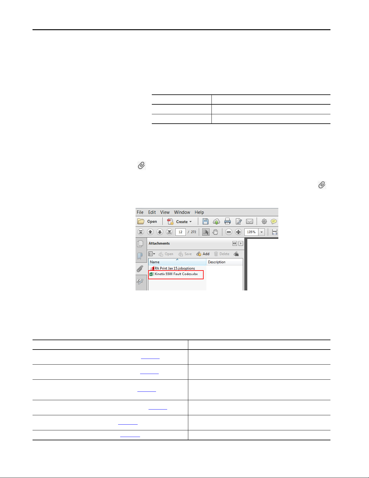
The Microsoft Excel spreadsheet that is attached to this publication contains
fault code descriptions. To use the spreadsheet file, click the Attachments link
, right-click the spreadsheet file, and save the file to your computer.
If the PDF file opens in a browser and you don't see the Attachments link ,
download the PDF file and reopen the file with the Adobe Acrobat Reader
application.
Additional Resources
These documents contain additional information concerning related products
from Rockwell Automation.
Table 1 - Additional Resources
Resource Description
Kinetix Rotary Motion Specifications Technical Data, publication KNX-TD001
Kinetix Linear Motion Specifications Technical Data, publication KNX-TD002
Kinetix Servo Drives Specifications Technical Data, publication KNX-TD003
Kinetix Motion Accessories Specifications Technical Data, publication KNX-TD004
AC Line Filter Installation Instructions, publication 2198-IN003
Shunt Resistor Installation Instructions, publication 2097-IN002 Provides information on how to install and wire Bulletin 2097 shunt resistors.
12 Rockwell Automation Publication 2198-UM001I-EN-P - May 2019
Product specifications for Kinetix VP (Bulletin VPL, VPF, VPH, and VPS), MP-Series™
(Bulletin MPL, MPM, MPF, and MPS), TL-Series™, and HPK-Series™ rotary motors.
Product specifications for MP-Series (Bulletin MPAS ballscrew, MPAR, and MPAI)
and LDAT-Series linear actuators.
Product specifications for Kinetix Integrated Motion over the EtherNet/IP network,
Integrated Motion over sercos interface, EtherNet/IP networking, and component
servo drive families.
Product specifications for Bulletin 2090 motor and interface cables, low-profile
connector kits, drive power components, and other servo drive accessory items.
Provides information on how to install AC line filters designed for Kinetix 5500 and
Kinetix 5700 servo drive systems.
Table 1 - Additional Resources (continued)
Resource Description
System Design for Control of Electrical Noise Reference Manual,
publication GMC-RM001
Kinetix Motion Control Selection Guide, publication KNX-SG001
Kinetix 5500 Drive Systems Design Guide, publication KNX-RM009
Rockwell Automation Product Selection
website http://www.rockwellautomation.com/global/support/selection.page
Motion Analyzer System Sizing and Selection Tool
website https://motionanalyzer.rockwellautomation.com/
Product Certifications website, rok.auto/certifications
Motor Nameplate Datasheet Entry for Custom Motor Applications Application Technique,
publication 2198-AT002
Vertical Load and Holding Brake Management Application Technique,
publication MOTION-AT003
Integrated Motion on the EtherNet/IP Network Reference Manual,
publication MOTION-RM003
Integrated Motion on the EtherNet/IP Network Configuration and Startup User Manual,
publication MOTION-UM003
GuardLogix 5570 Controllers User Manual, publication 1756-UM022
GuardLogix 5580 Controllers User Manual, publication 1756-UM543
Compact GuardLogix 5370 Controllers User Manual, publication 1769-UM022
Compact GuardLogix 5380 Controllers User Manual, publication 5069-UM001
GuardLogix 5570 and Compact GuardLogix 5370 Controller Systems Safety Reference
Manual, publication 1756-RM099
GuardLogix 5580 and Compact GuardLogix 5380 Controller Systems Safety Reference
Manual, publication 1756-RM012
ControlFLASH Firmware Upgrade Kit User Manual, publication 1756-UM105
Rockwell Automatio n Industrial Automation Glossary, publication AG-7 .1
Industrial Automation Wiring and Grounding Guidelines, publication 1770-4.1
Information, examples, and techniques designed to minimize system failures
caused by electrical noise.
Overview of Kinetix servo drives, motors, actuators, and motion accessories
designed to help make initial decisions for the motion control products best suited
for your system requirements.
System design guide to select the required (drive specific) drive module, power
accessory, feedback connector kit, and motor cable catalog numbers for your
Kinetix 5500 drive and Kinetix VP motor motion control system.
Online product selection and system configuration tools, including AutoCAD (DXF)
drawings.
Comprehensive motion application sizing tool used for analysis, optimization,
selection, and validation of your Kinetix Motion Control system.
Provides declarations of conformity, certificates, and other certification details.
Provides information on the use of nameplate data entry for custom induction
motors and permanent-magnet motors that are used in applications with
Kinetix 5700 servo drives.
Provides information on vertical loads and how the servo motor holding-brake
option can be used to help keep a load from falling.
Information on the AXIS_CIP_DRIVE attributes and the configuration software
control modes and methods.
Information on how to configure and troubleshoot your ControlLogix® and
CompactLogix™ EtherNet/IP network modules.
Provides information on how to install, configure, program, and use ControlLogix
controllers and GuardLogix® controllers in Studio 5000 Logix Designer® projects.
Provides information on how to install, configure, program, and use CompactLogix
and Compact GuardLogix controllers.
Provides information on how to achieve and maintain Safety Integrity Level (SIL)
and Performance Level (PL) safety application requirements for GuardLogix and
Compact GuardLogix controllers.
Provides information on how to upgrade your drive firmware by using
ControlFLASH ™ software.
A glossary of industrial automation terms and abbreviations.
Provides general guidelines for installing a Rockwell Automation industrial system.
Preface
You can view or download publications at
http://www.rockwellautomation.com/global/literature-library/overview.page
Rockwell Automation Publication 2198-UM001I-EN-P - May 2019 13
.

Preface
Notes:
14 Rockwell Automation Publication 2198-UM001I-EN-P - May 2019
Chapter 1
Start
Use this chapter to become familiar with the Kinetix® 5500 drive system and
obtain an overview of the installation configurations.
Top ic Pa ge
About the Kinetix 5500 Servo Drive System 15
Drive Hardware and Input Power Configurations 17
Motor Feedback and Feedback-only Configurations 22
Typical Communication Configurations 23
Safe Torque-off Configurations 26
Catalog Number Explanation 29
Agenc y Compliance 30
About the Kinetix 5500 Servo Drive System
Table 2 - Kinetix 5500 Drive System Overview
Drive System
Component
Kinetix 5500
Servo Drives
Kinetix 5500
Capacitor Module
Shared-bus
Connector Kits
Feedba ck
Connector Kit
Hiperface to DSL
Converter Kit
I/O Connector Kits
Connector Sets
Cat. No. Description
2198-Hxxx-ERS
2198-Hxxx-ERS2
2198-CAPMOD-1300
2198-H040-x-x Input wiring connectors and DC bus T-connector for frame 1 and 2 servo drives.
2198-H070-x-x Input wiring connectors and DC bus T-connector for frame 3 servo drives.
2198-KITCON-DSL Replacement feedback connector kit with 2-pin connector plug and grounding plate inside the connector housing.
2198-H2DCK
(series B or later)
2198-KITCON-IOSP Replacement I/O connector kit (spring clamp) for I/O (IOD) connector.
2198-KITCON-IOSC Replacement I/O connector kit (screw terminal) for I/O (IOD) connector.
2198-KITCON-PWR40 Replacement connector set, 40 A, for frame 1 and frame 2 drives.
2198-KITCON-PWR70 Replacement connector set, 70 A, for frame 3 drives.
2198-KITCON-CAP1300 Replacement connector set, 40 A, for capacitor module.
200V-class (single-phase or three-phase) and 400V-class (three-phase) drives operate in standalone and multi-axis shared AC,
shared DC, shared AC/DC, and shared AC/DC hybrid configurations. Modules are zero-stacked from drive-to-drive and use the
shared-bus connection system to extend power in multi-axis configuration s. Safe torque-off via hardwired (STO) connector.
Same power structures as 2198-Hxxx-ERS servo drives with standalone and multi-axis bus-sharing capability. Safe torque-off via
the EtherNet/IP™ network.
Use for energy storage and/or to improve performance in applications producing regenerative energy and requiring shorter duty
cycles (1360 μf). Modules are zero-stacked side-by-side with servo drives and use the shared-bus connection system to extend
power.
Use the 2198-H2DCK Hiperface-to-DSL feedback converter kit with MP-Series™ (Bulletin MPL, MPM, MPF, and MPS) rotary
motors, MP-Series (Bulletin MPAS ballscrew, MPAR, MPAI) linear actuators, and LDAT-Series linear thrusters.
The Kinetix 5500 servo drives are designed to provide a Kinetix Integrated
Motion solution for your drive and motor/actuator application.
Rockwell Automation Publication 2198-UM001I-EN-P - May 2019 15

Chapter 1 Start
Table 2 - Kinetix 5500 Drive System Overview (continued)
Drive System
Component
Encoder Output
Module
Logix 5000™
Controller Platform
Studio 5000®
Environment
Rotary Servo
Motors
Linear Actuators
Induction Motors N/A Induction motors with open loop frequency control are also supported.
Cables
AC Line Filters
24V DC Power
Supply
External Shunt
Resistors
Cat. No. Description
2198-ABQE
Bulletin 1769
Bulletin 5069
1756-EN2T module
1756-EN2TR module
1756-EN3TR module
N/A
VPL-Axxxx, VPL-Bxxxx
VPF-Axxxx, VPF-Bxxxx
VPH-Axxxx, VPH-Bxxxx
VPS-Bxxxx
MP-Series
Kinetix VP
MP-Series
LDAT-Series
2090-CSxM1DF-xxAxxx
2090-CSxM1DG-xxAxxx
2090-CFBM7DF-CEAxxx Bulletin 2090 motor feedback cables for MP-Series motors and actuators.
2090-CPxM7DF-xxAxxx Bulletin 2090 motor power/brake cables for MP-Series motors and actuators.
1585J-M8CBJM-x Ethernet cables are available in standard lengths. Shielded cable is recommended.
2198-DB08-F
2198-DB20-F
2198-DB42-F
2198-DBR20-F
2198-DBR40-F
2198-DBR90-F
1606-XLxxx Bulletin 1606 24V DC power supply for control circuitry, digital inputs, safety, and motor brake.
2097-R6 and 2097-R7 Bulletin 2097 external passive shunt resistors for when the internal shunt capability of the drive is exceeded.
The Allen-Bradley® encoder output module is a DIN-rail mounted EtherNet/IP network-based standalone module capable of
outputting encoder pulses to a customer-supplied peripheral device (cameras, for example, used in line-scan vision systems).
Integrated Motion on the EtherNet/IP network in CompactLogix™ 5370, CompactLogix 5380, and CompactLogix 5480 controllers
and Integrated Safety in Compact GuardLogix® 5370 controllers. Linear, device-level ring (DLR), and star topology is supported.
EtherNet/IP network communication modules for use with ControlLogix® 5570, ControlLogix 5580, and GuardLogix 5570
controllers. Linear, device-level ring (DLR), and star topology is supported.
Studio 5000 Logix Designer® application, version 21.00 or later, provides support for programming, commissioning, and
maintaining the CompactLogix and ControlLogix controller families. Version 24.00 or later is required for 2198-Hxxx-ERS2 servo
drives.
Compatible rotary motors include 200V and 400V-class Kinetix VP (Bulletin VPL, VPF, VPH, and VPS).
Compatible rotary motors include 200V and 400V-class MP-Series (Bulletin MPL, MPM, MPF, and MPS) when used with the
Hiperface-to-DSL feedback converter kit.
Compatible linear actuators include 200V and 400V-class Kinetix VP (Bulletin VPAR), MP-Series (Bulletin MPAS ballscrew, MPAR,
and MPAI) and LDAT-Series when used with the Hiperface-to-DSL feedback converter kit.
Bulletin 2090 flying-lead single-cable for motor power, feedback, and 24V DC brake power with Kinetix VP motors. Designed
specifically for Kinetix 5500 servo drives.
Bulletin 2090 flying-lead single cable for motor power, feedback, and 24V DC brake power with Kinetix VP motors and actuators.
Designed with longer leads than 2090-CSxM1DF cables to accommodate Kinetix 5500 or Kinetix 5700 drive families.
Bulletin 2198 three-phase AC line filters are required to meet CE and available for use in all Kinetix 5500 drive systems. Use
2198-DBxx-F filters as field replacements in existing installations. Select 2198-DBRxx-F filters for all new systems and do not
remove the servo drive ground screws.
Bulletin 2198 three-phase AC line filters are required to meet CE and available for use with all Kinetix 5500 drive systems. Select
2198-DBRxx-F filters for all new systems and do not remove the servo drive ground screws.
16 Rockwell Automation Publication 2198-UM001I-EN-P - May 2019
Start Chapter 1
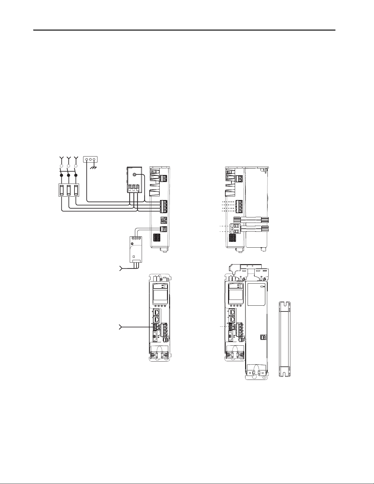
Single-phase or
Three- phase
Input Power
Line
Disconnect
Device
Input
Fusin g
2198-Hxxx-ERSx Drive
(front view)
2097-Rx
Shunt Resistor
(optional component)
2198-Hxxx-ERSx Drive
(top view)
AC Input Power
Bonded Cabinet
Ground Bus
Mains AC and 24V input
wired to standard input
connectors.
2198-DBRxx-F
AC Lin e Filter
(can be required
for CE)
Shared DC (DC common bus)
Shared 24V (control power input)
2198-Hxxx-ERSx Drive (top view)
with 2198-CAPMOD-1300
Capacitor Module
2198-H0x0-x-x shared-bus
connection system for bussharing configurations.
Mains AC input wired to
standard input connector.
Digital Inputs
to Sensors and Control String
1606-XLxxx
24V DC Control, Digital Inputs,
and Motor Brake Power
(customer-supplied)
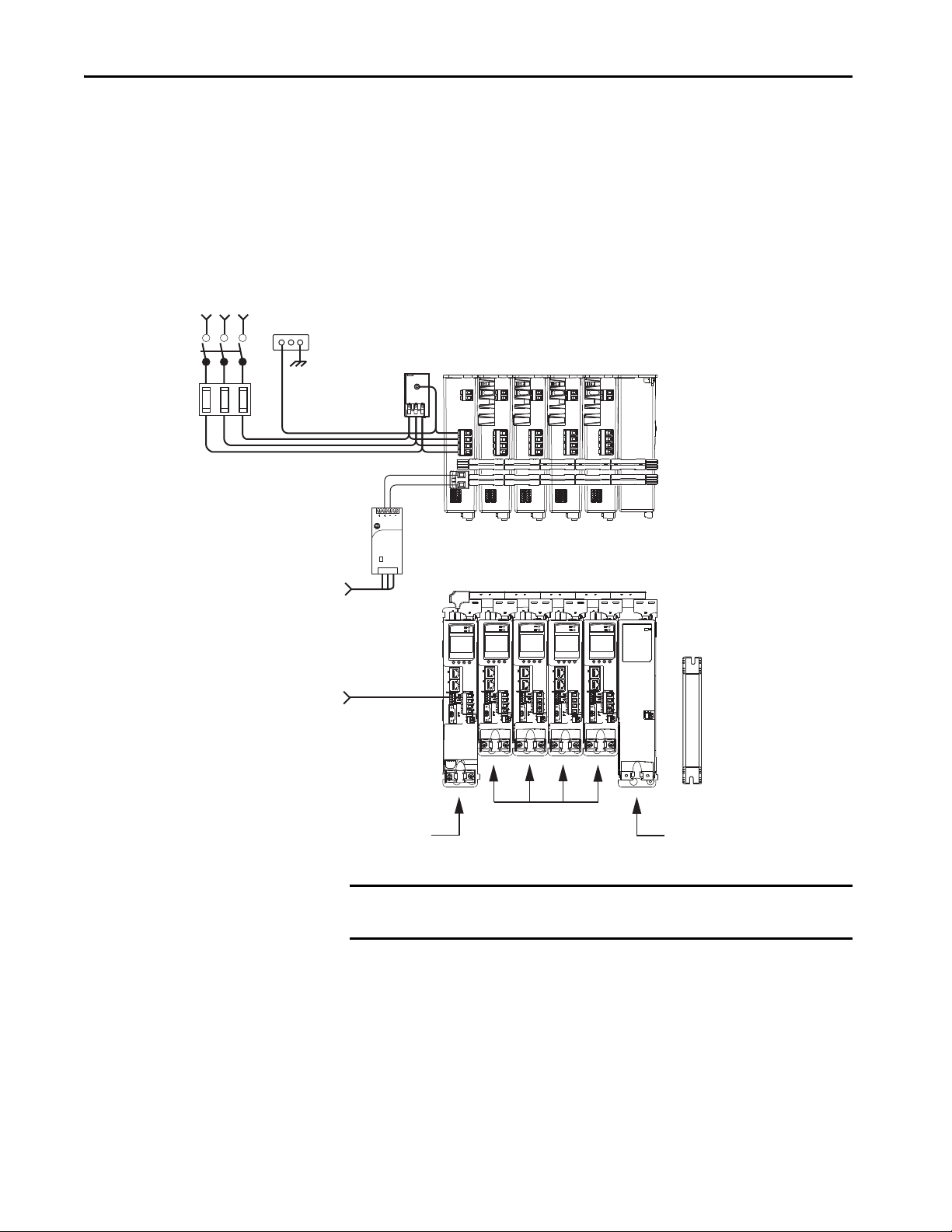
Drive Hardware and Input Power Configurations
Typical Kinetix 5500 systems include single-phase and three-phase standalone
configurations, three-phase shared AC, shared AC/DC, shared DC, and
shared AC/DC hybrid configurations.
Standalone Configurations
In these examples, a single standalone drive is shown with and without the
Bulletin 2198 capacitor module.
Figure 1 - Typical Kinetix 5500 Standalone Installation
Allen-Bradley
1606-XL
Power Supply
Input
Rockwell Automation Publication 2198-UM001I-EN-P - May 2019 17
Chapter 1 Start
1606-XL
Power Supply
Input
Allen-Bradley
Kinetix 5500 Servo Drives (top view)
(2198-H008-ERS drives shown)
2097-Rx
Shunt Resistor
(optional component)
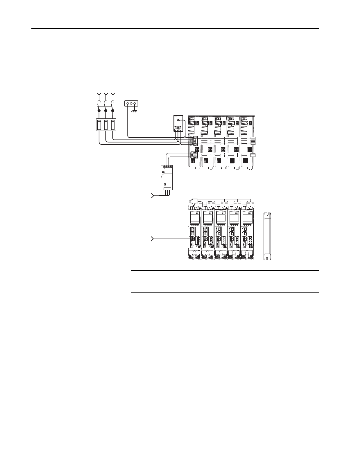
Line
Disconnect
Device
Input
Fusing
Three-phase
Input Power
AC Input Power
Bonded Cabinet
Ground Bus
Kinetix 5500 Servo Drives (front view)
(2198-H008-ERS drives shown)
2198-DBRxx-F
AC Line Filter
(can be required for CE)
Share d AC (mains AC input)
Shared 24V (control power input)
Shared-bus connection system
for bus-sharing configurations.
Digital Inputs
to Sensors and Control String
1606-XLxxx
24V DC Control, Digital Inputs,
and Motor Brake Power
(customer-supplied)
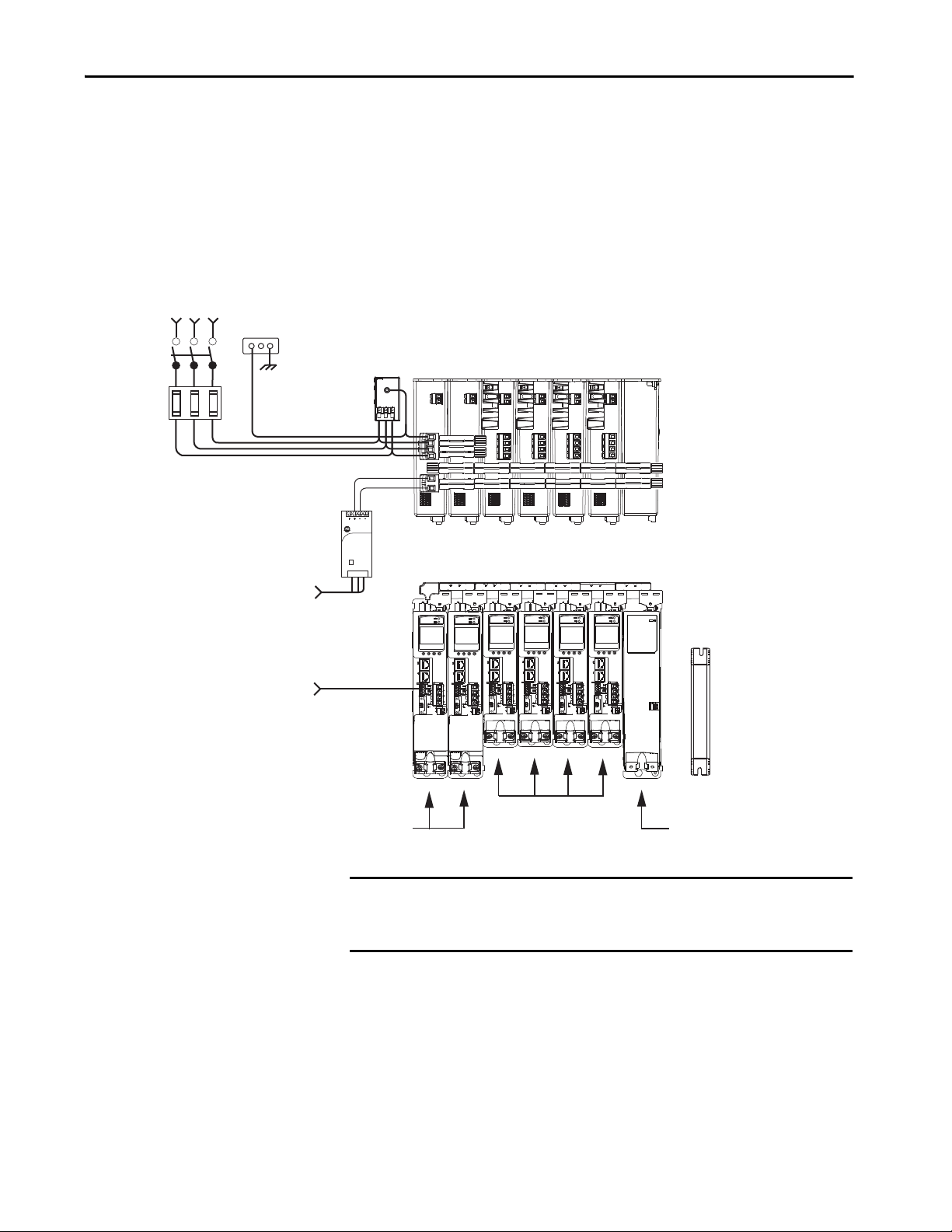
In this example, three-phase AC power and 24V control power is shared in a
multi-axis configuration. All drives must have the same power rating (catalog
number).
Figure 2 - Typical Shared AC Installations
IMPORTANT In shared AC configurations, all drives must have the same power rating.
Shared AC configurations do not support Bulletin 2198 capacitor modules.
18 Rockwell Automation Publication 2198-UM001I-EN-P - May 2019
Start Chapter 1
1606-XL
Power Supply
Input
Allen-Bradley
2097-Rx
Shunt Resistor
(optional component)
Line
Disconnect
Device
Input
Fusing
Three-phase
Input Power
AC Input Power
Bonded Cabinet
Ground Bus
2198-DBRxx-F
AC Line Filter
(can be required for CE)
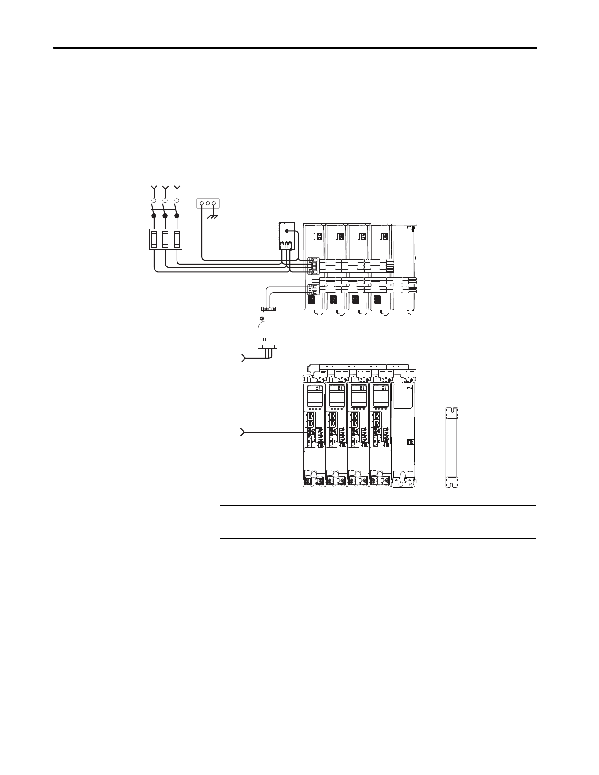
Kinetix 5500 Servo Drives (top view)
(2198-H015-ERS drives shown)
Kinetix 5500 Servo Drives (front view)
(2198-H015-ERS drives shown)
Share d AC (mains AC input)
Shared DC (DC common bus)
Shared 24V (control power input)
2198-CAPMOD-1300 Capacitor Module
(optional component)
Shared-bus connection system for
bus-sharing configurations.
Digital Inputs
to Sensors and Control String
1606-XLxxx
24V DC Control, Digital Inputs,
and Motor Brake Power
(customer-supplied)
Shared AC/DC Configurations
In this example, three-phase AC input power, 24V control power, and DC-bus
power are shared in a multi-axis configuration. All drives must be the same
power rating (catalog number).
Figure 3 - Typical Shared AC/DC Installations
Rockwell Automation Publication 2198-UM001I-EN-P - May 2019 19
IMPORTANT In shared AC/DC configurations, all drives must have the same power rating
(catalog number).
Chapter 1 Start
Kinetix 5500 Servo Drive System (top view)
2097-Rx
Shunt Resistor
(optional component)
Line
Disconnect
Device
Input
Fusing
Three-phase
Input Power
2198-H040-ERS
Common-bus Leader Drive
AC Inp ut Power
Bonded Cabinet
Ground Bus
Kinetix 5500 Servo Drive System (front view)
2198-H008-ERS
Common-bus
Follower Drives
2198-DBRxx-F
AC Line Filt er
(can be required for CE)
Shared DC (DC common bus)
Shared 24V (control power input)
2198-CAPMOD-1300 Capacitor Module
(optional component)
Shared-bus connection system
for bus-sharing configurations.
Digital Inputs
to Sensors and Control String
1606-XLxxx
24V DC Control, Digital Inputs,
and Motor Brake Power
(customer-supplied)
Shared DC Common-bus Configurations
In this multi-axis example, the common-bus leader (sourcing) drive receives
three-phase AC input power and supplies DC power to common-bus follower
(sinking) drives. The common-bus leader-drive power rating is greater than or
equal to the power rating of each follower drive.
Figure 4 - Typical Shared DC Common-bus Installations
Allen-Bradley
1606-XL
Power Supply
Input
(
IMPORTANT In shared DC common-bus configurations, the leader drive power rating
must be greater than or equal to the power rating of the follower drives.
20 Rockwell Automation Publication 2198-UM001I-EN-P - May 2019
Start Chapter 1
1606-XL
Power Supply
Input
Allen-Bradley
Kinetix 5500 Servo Drive System (top view)
2097-Rx
Shunt Resistor
(optional component)
Line
Disconnect
Device
Input
Fusing
Three-phase
Input Power
Digital Inputs
to Sensors and Control String
2198-H040-ERS
Common-bus (converter)
Leader Drives
1606-XLxxx
24V DC Control, Digital Inputs,
and Motor Brake Power
(customer-supplied)
AC Input Po wer
Bonded Cabinet
Ground Bus
Kinetix 5500 Servo Drive System (front view)
2198-H008-ERS
Common-bus (inverter)
Follower Drives
2198-DBRxx-F
AC Line Filter
(can be required for CE)
Share d AC (mains AC input)
Shared DC (DC common bus)
Shared 24V (control power input)
Shared-bus connection system for
bus-sharing configurations.
2198-CAPMOD-1300 Capacitor Module
(optional component)
Shared AC/DC Hybrid Configuration
In this multi-axis example, three-phase AC input power is supplied to two
converter drives. The converter drive ratings must be the same, and greater
than or equal to the power ratings of the inverter drives. This parallel converter
configuration increases the DC-bus power supplied to the inverter drives.
Figure 5 - Typical Shared AC/DC Bus Hybrid Installations
IMPORTANT In shared AC/DC hybrid configuration, the converter drives must have the
same power rating and must be greater than or equal to the power ratings
of the inverter drives.
Rockwell Automation Publication 2198-UM001I-EN-P - May 2019 21
Chapter 1 Start
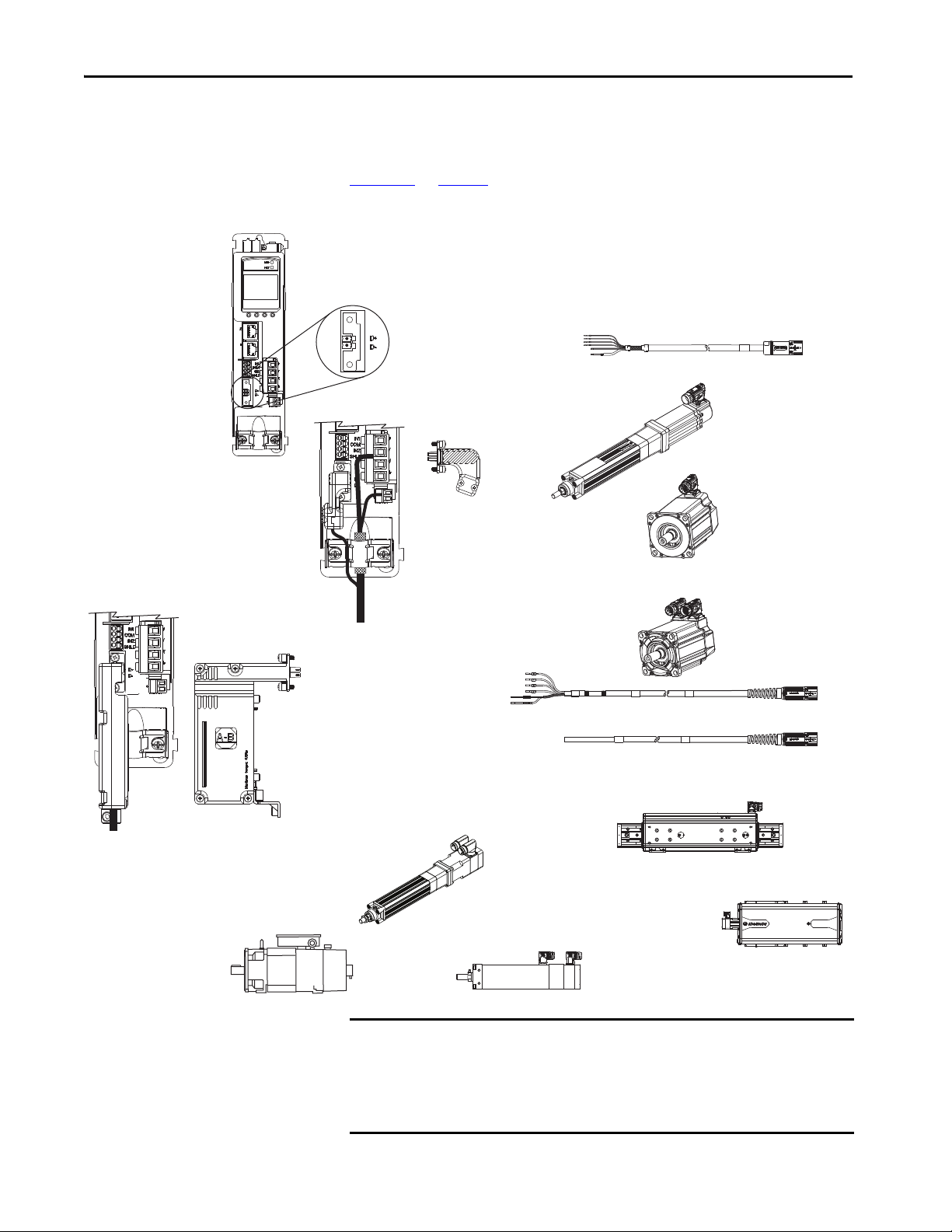
2090-CSBM1DF or 2090-CSBM1DG
Single Motor Cables
2198-KITCON-DSL Connector Kit
• Accepts DSL motor feedback from Kinetix VP
(Bulletin VPL, VPF, VPH, VPS) rotary motors
and Kinetix VP electric cylinders.
• Feedback-only (DSL)
Bulletin 2090 Motor Power and Feedback Cables
MP-Series Linear Actuators
(MPAR-B3xxxx electric cylinder is shown)
MP-Series Rotary Motors
(MPL-Bxxxx motor is shown)
LDAT-Sxxxxxx-xDx
Linear Thrusters
2198-H2DCK Converter Kit
Converts 15-pin Hiperface feedback into 2-pin DSL feedback for:
• MP-Series rotary motors and linear actuators
• LDAT-Series linear thrusters
• Feedback-only (absolute single-turn/multi-turn Hiperface)
2-pin Motor Feedback
(MF) Connector
2198-Hxxx-ERSx Drive
(front view)
MP-Series Linear Actuators
(MPAS-B9xxx ballscrew linear stage is shown)
Kinetix VP Rotary Motors
(VPL-Bxxxx motor is shown)
MP-Series Linear Actuators
(MPAI-B3xxxx heavy-duty electric c ylinder is shown)
Induction Rotary Motors
(no feedback, V/Hz)
Kinetix VP Electric Cylinders
(Bulletin VPAR)
Motor Feedback and Feedback-only Configurations
Feedback connections are made at the 2-pin motor feedback (MF) connector.
These examples illustrate how you can use the Bulletin 2198 connector kits for
making these connections. To see motor power and brake connections, refer to
Chapter 5
Figure 6 - Feedback Configuration Examples
on page 73.
IMPORTANT In 2198-H2DCK converter kit applications, you can replace the 2090-
CPxM7DF power/brake cable with a 2090-CSBM1DF single motor cable, and
reuse the 2090-CFBM7DF feedback cable. This increases the maximum cable
length for 18 and 14 AWG single cables to 50 m (164 ft). 2090-CSxM1DF-
10Axxx (10 AWG) cables do not support this 50 m (164 ft) option.
22 Rockwell Automation Publication 2198-UM001I-EN-P - May 2019

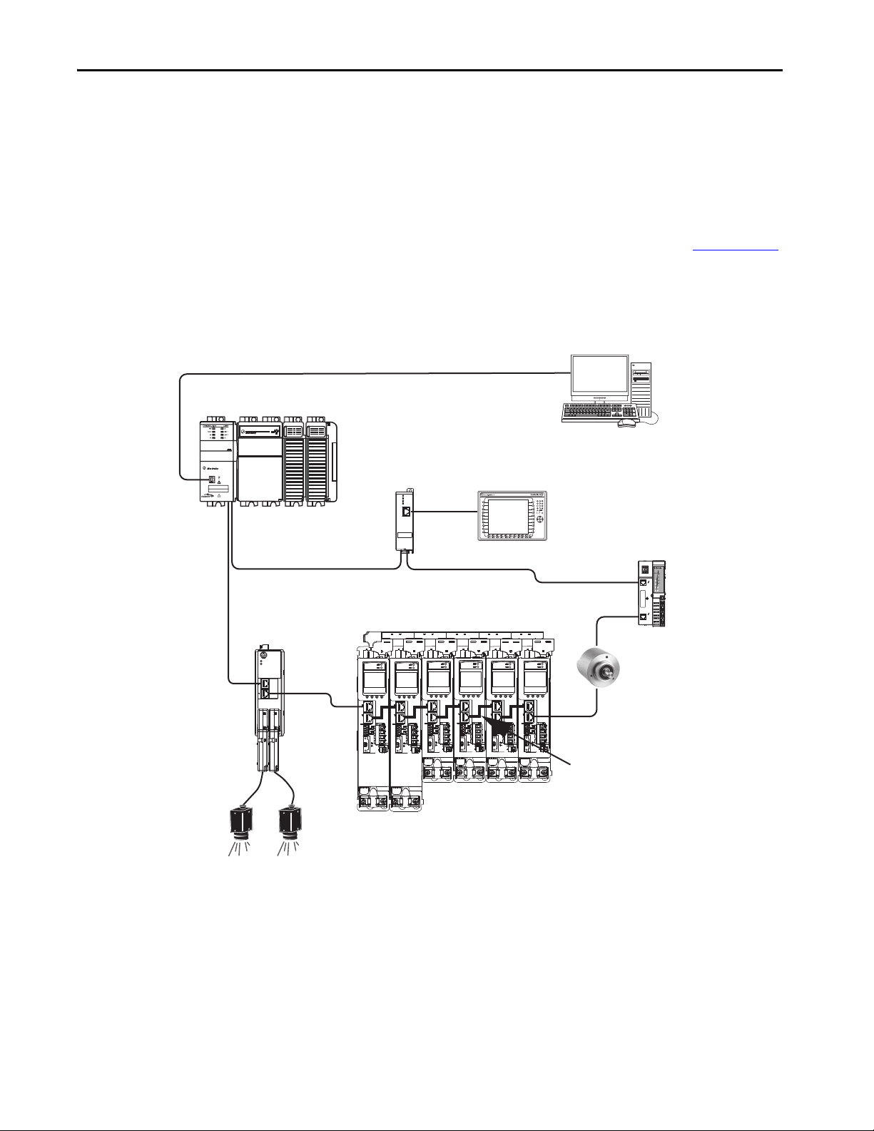
Start Chapter 1
2198-ABQE
Encoder Output Module
Compac tLogix 5370 Controller
Studio 5000 Logix Designer
Application
1585J-M8CBJM-x
Ethernet (shielded) Cable
1734-AENTR POINT I/O™
EtherNet/IP Adapter
CompactLogix Controller Programming Network
PanelView™ Plus
Display Terminal
1585J-M8CBJM-OM15
0.15 m (6 in.) Ethernet cable
for drive-to-drive connections.
Kinetix 5500 Servo Drive System
842E-CM Integrated
Motion Encoder
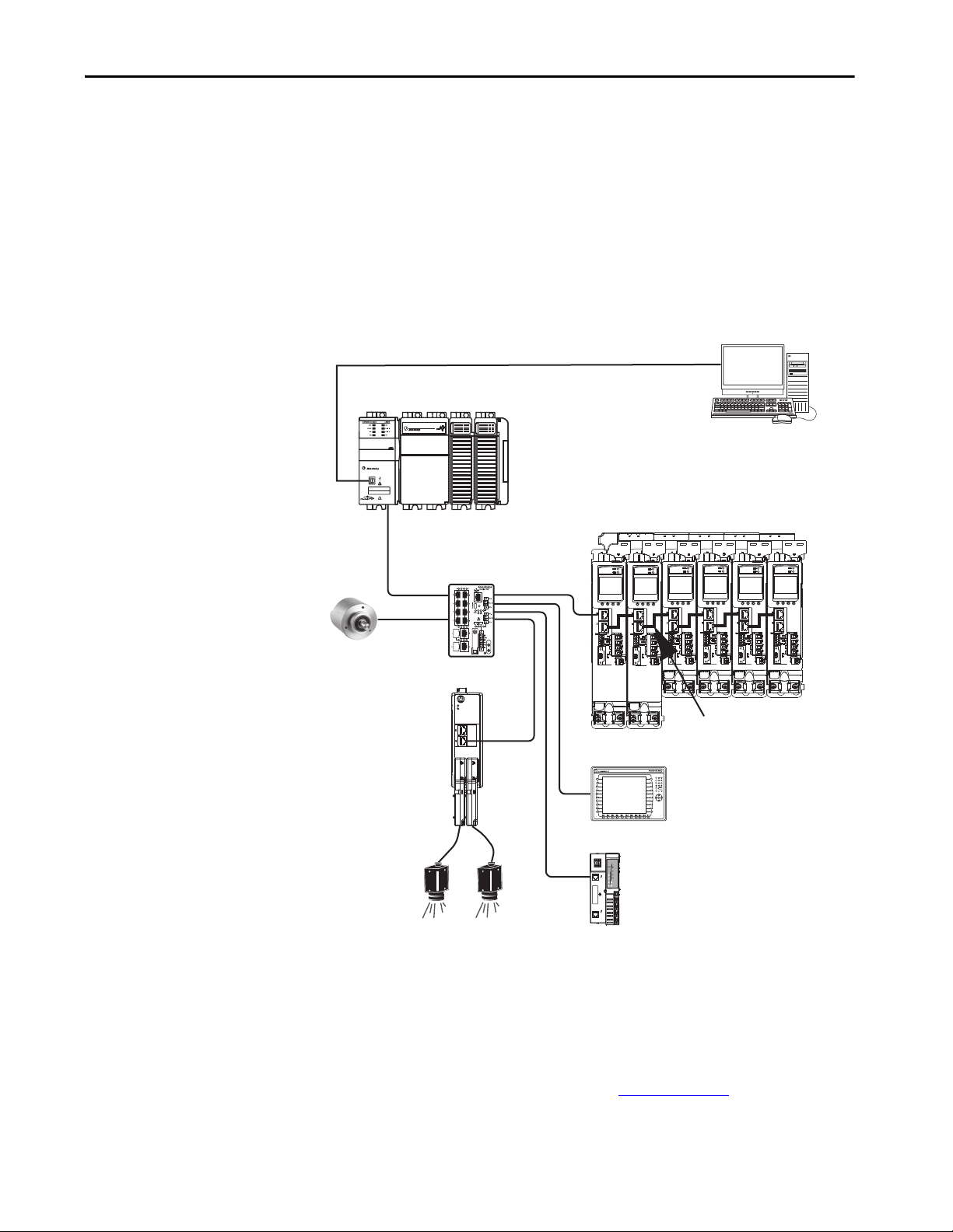
Typical Communication Configurations
The Kinetix 5500 drives support any Ethernet topology including linear, ring,
and star by using ControlLogix, GuardLogix, or CompactLogix controllers.
These examples feature the CompactLogix 5370 programmable automation
controllers (Bulletin 1769) with support for Integrated Motion over the
EtherNet/IP network.
Refer to CompactLogix Controllers Specifications Technical Data, publication
1769-TD005
, for more information on CompactLogix 5370 L1, L2, and L3
controllers.
Linear Topology
In this example, all devices are connected in linear topology. The Kinetix 5500
drives include dual-port connectivity, however, if any device becomes
disconnected, all devices downstream of that device lose communication.
Devices without dual ports must include the 1783-ETAP module or be
connected at the end of the line.
Figure 7 - Kinetix 5500 Linear Communication Installation
00:00:BC:2E:69:F6
1 (Front)
2 (Rear)
MOD
NET
OUTPUT-A OUTPUT-B
1734-AENTR
02
0
POINT I O
Module
Status
Network
Activity
Network
Status
Point Bus
Status
Link 1
Activity/
System
Status
Power
Field
Power
Link 2
Activity/
Status
Rockwell Automation Publication 2198-UM001I-EN-P - May 2019 23
Chapter 1 Start
1 (Front)
2 (Rear)
00:00:BC:2E:69:F6
02
0
1734-AENTR
Module
Status
Network
Activity
Network
Status
Point Bus
Status
System
Power
Field
Power
POINT I O
Link 1
Activity/
Status
Link 2
Activity/
Status
MOD
NET
OUTPUT-A OUTPUT-B
2198-ABQE
Encoder Output Module
1734-AENTR POINT I/O
EtherNet/IP Adapter
CompactLogix Controller Programming Network
1783-ETAP
Module
1585J-M8CBJM-OM15
0.15 m (6 in.) Ethernet cable
for drive-to-drive connections.
Panel View Plus
Display Terminal
Kinetix 5500 Servo Drive System
Compac tLogix 5370 Controller
Studio 5000 Logix Designer
Application
1585J-M8CBJM-x Ethernet
(shielded) Cable
842E-CM Integrated
Motion Encoder
Ring Topology
In this example, the devices are connected by using ring topology. If only one
device in the ring is disconnected, the rest of the devices continue to
communicate. For ring topology to work correctly, a device level ring (DLR)
supervisor is required (for example, the Bulletin 1783 ETAP device). DLR is
an ODVA standard. For more information, refer to the EtherNet/IP
Embedded Switch Technology Application Guide, publication ENET-AP005
Devices without dual ports, for example the display terminal, require a
1783-ETAP module to complete the network ring.
Figure 8 - Kinetix 5500 Ring Communication Installation
.
24 Rockwell Automation Publication 2198-UM001I-EN-P - May 2019
Start Chapter 1
2198-ABQE
Encoder Output Module
1585J-M8CBJM-x
Ethernet (shielded) Cable
1734-AENTR POINT I/O
EtherNet/IP Adap ter
CompactLogix Controller Programming Network
PanelView Plus
Display Terminal
1783-BMS
Stratix® 5700
Switch
1585J-M8CBJM-OM15
0.15 m (6 in.) Ethernet cable
for drive-to-drive connections.
Kinetix 5500 Servo Drive System
CompactLogix 53 70 Controller
Studio 5000 Logix Designer
Application
842E-CM Integrated
Motion Encoder
Star Topology
In this example, the devices are connected by using star topology. Each device is
connected directly to the switch.
Kinetix 5500 drives have dual ports, so linear topology is maintained from
drive-to-drive, but Kinetix 5500 drives and other devices operate
independently. The loss of one device does not impact the operation of other
devices.
Figure 9 - Kinetix 5500 Star Communication Installation
00:00:BC:2E:69:F6
1 (Front)
2 (Rear)
MOD
NET
OUTPUT-A OUTPUT-B
You can use the 842E-CM integrated motion encoder for applications
requiring an external encoder for gearing or camming to the Kineitx 5700
drive. By providing auxiliary feedback directly through the EtherNet/IP
network, the 842E-CM encoder helps eliminate the need for point-to-point
wiring while letting customers use the encoder in a variety of network
topologies. For more information, see the 842E-CM Integrated Motion on
EtherNet/IP Product Profile, publication 842ECM-PP001
.
Rockwell Automation Publication 2198-UM001I-EN-P - May 2019 25
Chapter 1 Start
1 (Front)
2 (Rear)
00:00:BC:2E:69:F6
1606-XL
Power Supply
Input
Allen-Bradley
OKFORCESDRUN
Logix5585
LINK
NET
TM
SAFETY ON
0000
DC INPUT
AC OUTPUT
DC INPUT
1585J-M8CBJM-x
Ethernet (shielded) Cable
Studio 5000 Logix Designer
Application
(version 21.0 or later)
AC Inp ut Power
Safety
Device
2198-Hxxx-ERS Servo Drives
(front view)
Digital Inputs to Sensors and Control String
1606-XLxxx
24V DC Control, Digital Inputs,
and Motor Brake Power
(customer-supplied)
Kinetix VP
Servo Motors
Module Definition
Configured with
Motion-only
Connection
Safe Torque-off
(STO) Connectors
Any Logix 5000 Controller
(CompactLogix 5370 controller is shown)
2198-Hxxx-ERS Servo Drives
(top view)
ControlLogix 5570 Controllers or
GuardLogix 5570 Safety Controllers
ControlLogix 5580 Controllers or
GuardLogix 5580 Safety Controllers
CompactLogix 53 70 Controllers or
Compact GuardLogix 5370 Safety Controllers
CompactLogix 5380 or 5480 Controllers or
Compact GuardLogix 5380 Safety Controllers
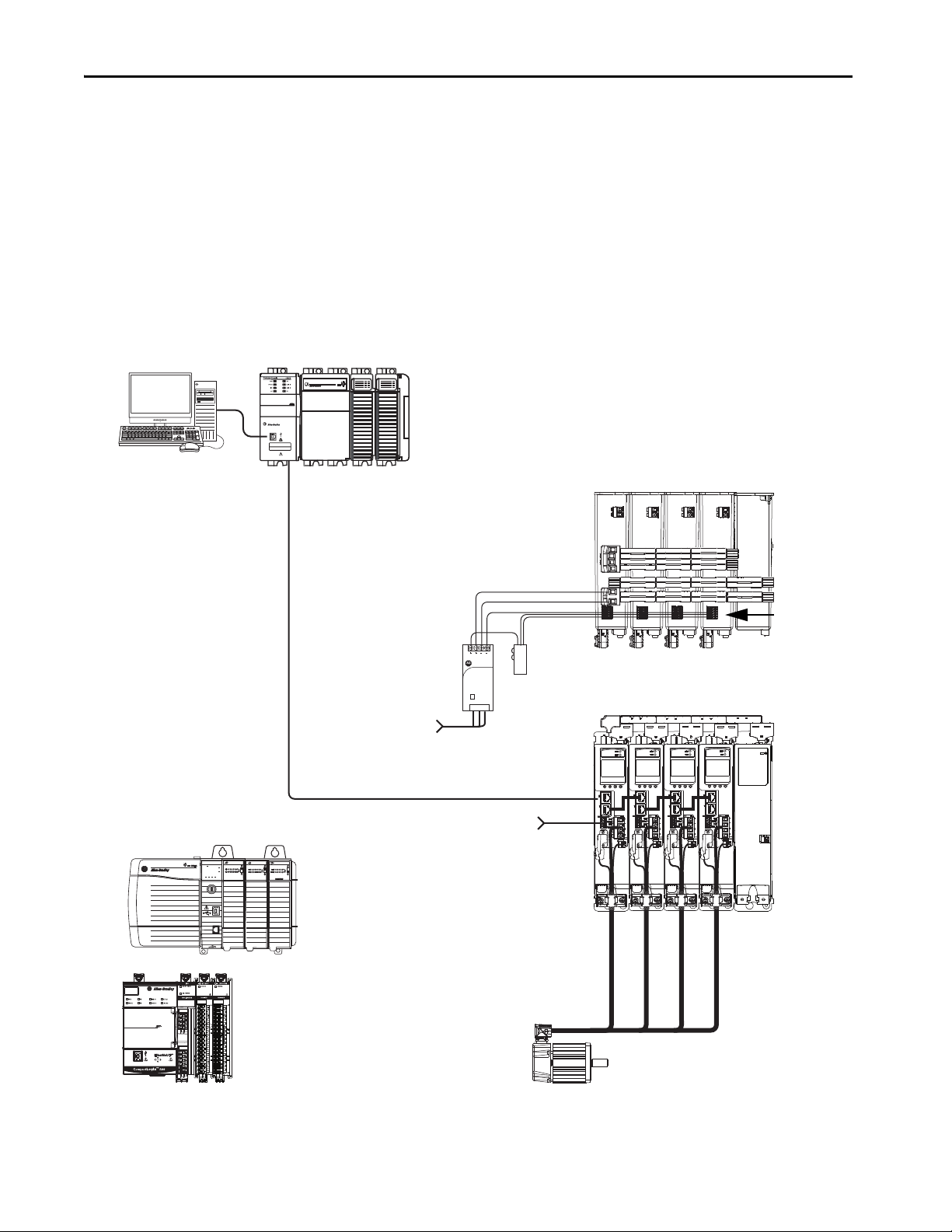
Safe Torque-off Configurations
Kinetix 5500 servo drives are available with safe torque-off via hardwired
connections or integrated over the EtherNet/IP network. These examples
illustrate the safe torque-off configuration options.
Hardwired Safety Configuration
The 2198-Hxxx-ERS drives use the safe torque-off (STO) connector for
wiring external safety devices and cascading hardwired safety connections from
one drive to another.
Figure 10 - Safe Torque-off (hardwired) Configuration
26 Rockwell Automation Publication 2198-UM001I-EN-P - May 2019
Start Chapter 1
1606-XL
Power Supply
Input
Allen-Bradley
LNK1LNK2NET OK
EtherNet/IP
1
2
1585J-M8CBJM-x
Ethernet (shielded) Cable
Studio 5000 Logix Designer
Application
(version 24.0 or later)
AC Input Po wer
2198-Hxxx-ERS2 Servo Drives
(top view)
2198-Hxxx-ERS2 Servo Drives
(front view)
Digital Inputs to Sensors and Control String
1606-XLxxx
24V DC Control, Digital Inputs,
and Motor Brake Power
(customer-supplied)
Kinetix VP
Servo Motors
1783-BMS
Stratix 5700
Switch
Module Definition
Configured with
Motion and Safety
Connections
1734-AENTR
POINT Guard I/O™
EtherNet/IP Adapter
Safety
Device
Motion and Safety Connections to the Drive
Compact GuardLogix 5370 Controller,
Compact GuardLogix 5380 Safety Controller or
GuardLogix 5570 Controller,
GuardLogix 5580 Safety Controller
(GuardLogix 5570 Safety Controller is shown)
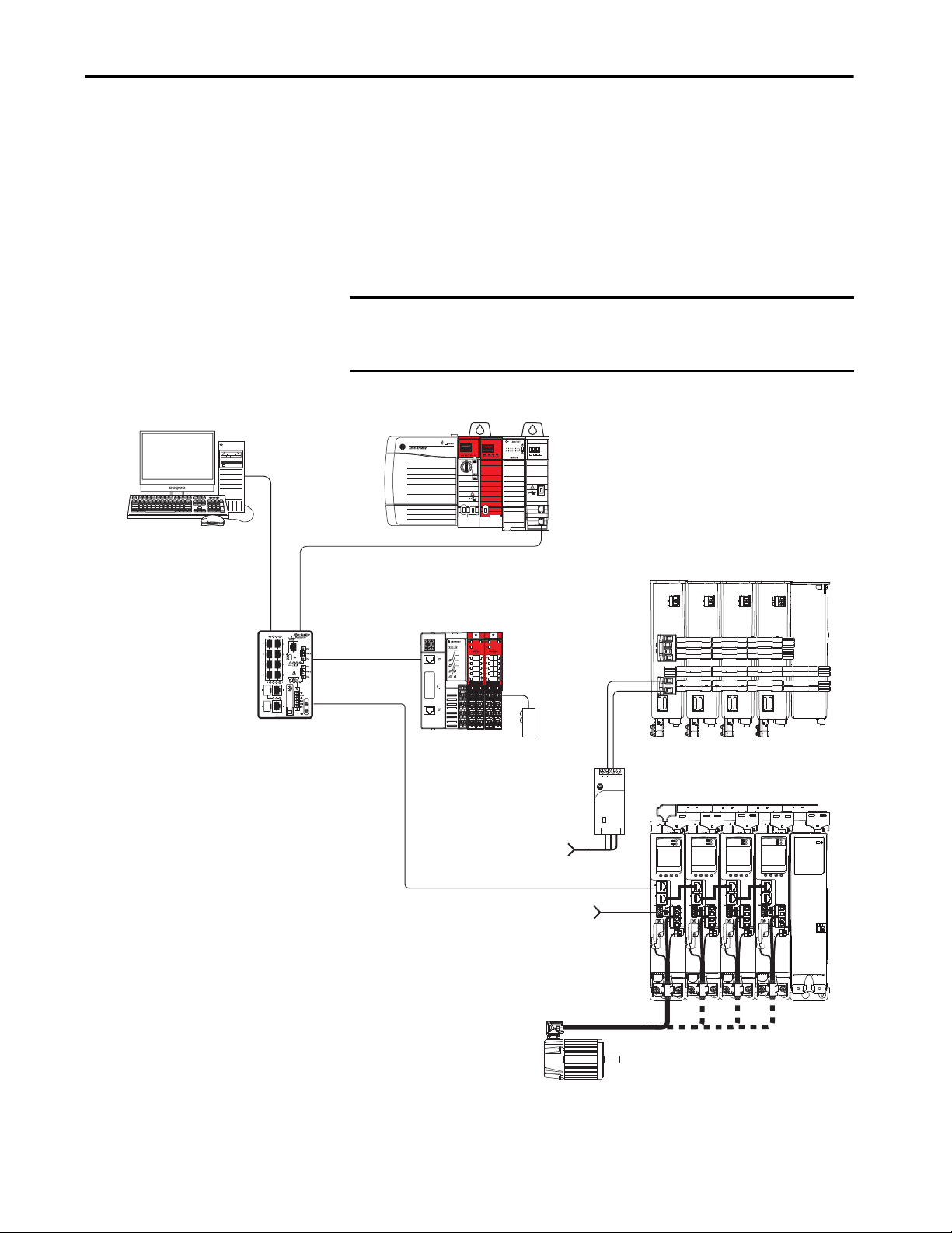
Integrated Safety Configurations
The GuardLogix 5570 or Compact GuardLogix 5370 safety controller issues
the safe torque-off (STO) command over the EtherNet/IP network and the
2198-Hxxx-ERS2 integrated safety drive executes the command.
In this example, a single GuardLogix safety controller makes a Motion and
Safety connection with the 2198-Hxxx-ERS2 integrated safety drives.
IMPORTANT If only one controller is used in an application with Motion and Safety
connections, the controller must be a GuardLogix 5570 or Compact
GuardLogix 5370 safety controller.
Figure 11 - Motion and Safety Configuration (single controller)
Rockwell Automation Publication 2198-UM001I-EN-P - May 2019 27
Chapter 1 Start
1585J-M8CBJM-x
Ethernet (shielded) Cable
Studio 5000 Logix Designer
Application
(version 24.0 or later)
AC Input Po wer
2198-Hxxx-ERS2 Servo Drives
(top view)
2198-Hxxx-ERS2 Servo Drives
(front view)
Digital Inputs to Sensors and Control String
1606-XLxxx
24V DC Control, Digital Inputs,
and Motor Brake Power
(customer-supplied)
Kinetix VP
Servo Motors
1734-AENTR
POINT Guard I/O
EtherNet/IP Adapter
1783-BMS
Stratix 5700
Switch
Motion Program
Module Definition
Configured with
Motion only
Connection
Safety Program
Module Definition
Config ured with S afety
only Connection
Safety
Device
Motion and Safety Connections to the Drive
Any Logix 5000 Controller
(ControlLogix 5570 controller is shown)
Compact GuardLogix 5370 Controller,
Compact GuardLogix 5380 Safety Controller or
GuardLogix 5570 Controller,
GuardLogix 5580 Safety Controller
(GuardLogix 5570 Safety Controller is shown)
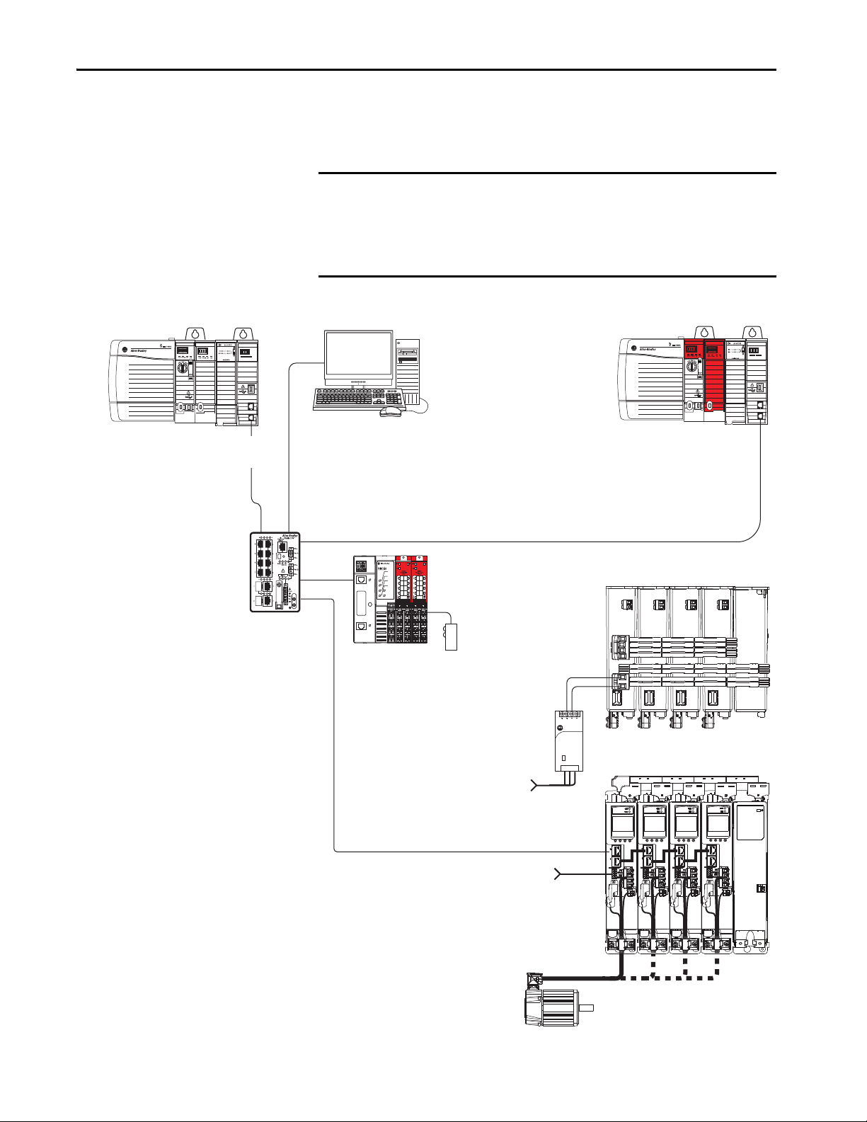
In this example, a non-safety controller makes the Motion-only connection
and a separate GuardLogix safety controller makes the Safety-only connection
with 2198-Hxxx-ERS2 integrated safety drives.
IMPORTANT If two controllers are used in an application with Motion-only and
Safety-only connections, the Safety-only connection must be a
GuardLogix 5570 or Compact GuardLogix 5370 safety controller and the
Motion-only connection must be a ControlLogix 5570 or
CompactLogix 5370 controller.
Figure 12 - Motion and Safety Configuration (multi-controller)
EtherNet/IP
LNK1LNK2NET OK
2
1
Allen-Bradley
1606-XL
Power Supply
Input
LNK1LNK2NET OK
EtherNet/IP
2
1
28 Rockwell Automation Publication 2198-UM001I-EN-P - May 2019

Start Chapter 1
Catalog Number Explanation
Drive Cat. No.
(hardwired STO)
2198-H003-ERS 2198-H003-ERS2
2198-H008-ERS 2198-H008-ERS2
2198-H015-ERS 2198-H015-ERS2
2198-H025-ERS 2198-H025-ERS2
2198-H040-ERS 2198-H040-ERS2
2198-H070-ERS 2198-H070-ERS2 3
Capacitor Module
Cat. No.
2198-CAPMOD-1300 2 650V DC, nom 1360 μF, min
Kinetix 5500 drive catalog numbers and performance descriptions.
Table 3 - Kinetix 5500 Servo Drive Catalog Numbers
Drive Cat. No.
(integrated STO)
Frame Size Input Voltage
1
2
195…264V rms, single-phase
195…264V rms, three-phase
324…528V rms, three-phase
195…264V rms, three-phase
324…528V rms, three-phase
Table 4 - Capacitor Module Catalog Number
Frame Size Rated Voltage Capacitance
Continuous Output
Power
kW
0.2 kW
0.3 kW
0.6 kW
0.5 kW
0.8 kW
1.6 kW
1.0 kW
1.5 KW
3.2 kW
2.4 kW
5.1 kW
4.0 kW
8.3 kW
7.0 kW
14.6 kW
Continuous Output
Current
A 0-pk
1.4
3.5
7.1
11.3
18.4
32.5
Table 5 - Shared-bus Connector Kit Catalog Numbers
Kit Cat. No. Frame Size Application Description
2198-H040-ADP-IN Frame 1 or 2 First drive
2198-H040-A-T
2198-H040-D-T DC sharing only DC bus T-connector
2198-H040-P-T Control power sharing only Control power T-connector
2198-H040-AD-T AC and DC-bus sharing AC and DC bus T-connectors
2198-H040-AP-T AC and control power sharing AC and control power T-connectors
2198-H040-DP-T DC and control power sharing DC and control power T-connectors
2198-H040-ADP-T AC, DC, and control power sharing AC, DC, and control power T-connectors
2198-H070-ADP-IN
2198-H070-A-T
2198-H070-D-T DC sharing only DC bus T-connector
2198-H070-P-T Control power sharing only Control power T-connector
2198-H070-AD-T AC and DC-bus sharing AC and DC bus T-connectors
2198-H070-AP-T AC and control power sharing AC and control power T-connectors
2198-H070-DP-T DC and control power sharing DC and control power T-connectors
2198-H070-ADP-T AC, DC, and control power sharing AC, DC, and control power T-connectors
Next drive is…
Frame 1 drives:
2198-H003-ERSx
2198-H008-ERSx
Frame 2 drives:
2198-H015-ERSx
2198-H025-ERSx
2198-H040-ERSx
Frame 3 drive:
2198-H070-ERSx
Next drive is…
Frame 3 drives:
2198-H070-ERSx
AC sharing only AC bus T-connector
First drive
AC sharing only AC bus T-connector
• Mains AC input wiring connector
• 24V DC input wiring connector
•DC bus T-connector
• Mains AC input wiring connector
• 24V DC input wiring connector
•DC bus T-connector
Rockwell Automation Publication 2198-UM001I-EN-P - May 2019 29
Chapter 1 Start
Agency Compliance
If this product is installed within the European Union and has the CE mark,
the following regulations apply.
ATT EN TI ON : Meeting CE requires a grounded system, and the method of
grounding the AC line filter and drive must match. Failure to do this renders
the filter ineffective and can cause damage to the filter. For grounding
examples, refer to Grounded Power Configurations
on page 75.
For more information on electrical noise reduction, refer to the System Design
for Control of Electrical Noise Reference Manual, publication GMC-RM001
To meet CE requirements, these requirements apply:
• Install an AC line filter (catalog number 2198-DBRxx-F) for input
power as close to the Kinetix 5500 drive as possible.
• Bond drive, capacitor module, and line filter grounding screws by using a
braided ground strap as shown in Figure 43 on page 80
.
• Use Bulletin 2090 single motor cables with Kinetix VP servo motors
and actuators. Use Bulletin 2090 motor power/brake and feedback
cables for other compatible Allen-Bradley motors and actuators.
• Combined motor cable length for all axes on the same DC bus must not
exceed 250 m (820 ft). Drive-to-motor cables must not exceed 50 m
(164 ft); however, use of continuous-flex cable and 2198-H2DCK
converter kit limits the maximum length.
.
Table 6 - Drive-to-Motor Maximum Cable Length
Kinetix VP Servo Motors Other Compatible Rotary Motors/Linear Actuators
Kinetix 5500 Servo Drive
Cat. No.
2198-H003-ERSx
2198-H008-ERSx
2198-H015-ERSx
2198-H025-ERSx
2198-H040-ERSx
2198-H070-ERSx 50 (164)
(1) When using 2090-CSBM1E1 cable in your continuous-flex application, the maximum cable length including the standard (non-flex) cable back to the drive, is 30 m (98.4 ft)
(2) Requires use of the 2198-H2DCK Hiperface-to-DSL (series B or later) feedback converter kit.
(3) The 20 m (65.6 ft) limitation is attributed to the 2090-CPxM7DF power/brake cable. In 2198-H2DCK converter kit applications, you can replace the 2090-CPxM7DF power/brake cable with a
2090-CSBM1DF or 2090-CSBM1DG single motor cable (and reuse the 2090-CFBM7DF feedback cable) to increase the maximum cable length t o 50 m (164 f t). This app lies to only 1 8 and 14 AWG sing le
cables. 2090-CSxM1Dx-10Axxx (10 AWG/M40 connector) single cables are not compatible with 2090-CPBM7DF-10Axxx (10 AWG/M40 connector) power/brake cables.
Standard (non-flex) Cables
Cat. No. 2090-CSxM1DF/DG-xxAAxx
m (ft)
50 (164) 30 (98.4)
50 (164)
Continuous-flex Cables
Cat. No. 2090-CSBM1DF/DG-xxAFxx
Cat. No. 2090-CSBM1E1-xxAFxx
m (ft)
(1)
Bulletin 2090 Motor/Actuator Cables
Cat. No. 2090-CxxM7DF
m (ft)
20 (65.6)
(3)
• Install the Kinetix 5500 system inside an approved enclosure. Run input
power wiring in conduit (grounded to the enclosure) outside of the
enclosure. Separate signal and power cables.
• Segregate input power wiring from control wiring and motor cables.
(2)
Refer to Appendix A on page 193
for input power wiring and drive/motor
interconnect diagrams.
30 Rockwell Automation Publication 2198-UM001I-EN-P - May 2019
 Loading...