

Allen-Bradley 2198-H040-ERS, 2198-H003-ERS, 2198-H025-ERS, 2198-H003-ERS2, 2198-H070-ERS User Manual
...Page 1

User Manual
Original Instructions
Kinetix 5500 Servo Drives
Catalog Numbers 2198-H003-ERS, 2198-H008-ERS, 2198-H015-ERS, 2198-H025-ERS, 2198-H040-ERS, 2198-H070-ERS
2198-H003-ERS2, 2198-H008-ERS2, 2198-H015-ERS2, 2198-H025-ERS2, 2198-H040-ERS2, 2198-H070-ERS2,
2198-CAPMOD-1300
Page 2
Important User Information
Read this document and the documents listed in the additional resources section about installation, configuration, and
operation of this equipment before you install, configure, operate, or maintain this product. Users are required to
familiarize themselves with installation and wiring instructions in addition to requirements of all applicable codes, laws,
and standards.
Activities including installation, adjustments, putting into service, use, assembly, disassembly, and maintenance are
required to be carried out by suitably trained personnel in accordance with applicable code of practice.
If this equipment is used in a manner not specified by the manufacturer, the protection provided by the equipment may
be impaired.
In no event will Rockwell Automation, Inc. be responsible or liable for indirect or consequential damages resulting from
the use or application of this equipment.
The examples and diagrams in this manual are included solely for illustrative purposes. Because of the many variables and
requirements associated with any particular installation, Rockwell Automation, Inc. cannot assume responsibility or
liability for actual use based on the examples and diagrams.
No patent liability is assumed by Rockwell Automation, Inc. with respect to use of information, circuits, equipment, or
software described in this manual.
Reproduction of the contents of this manual, in whole or in part, without written permission of Rockwell Automation,
Inc., is prohibited.
Throughout this manual, when necessary, we use notes to make you aware of safety considerations.
WARNING: Identifies information about practices or circumstances that can cause an explosion in a hazardous
environment, which may lead to personal injury or death, property damage, or economic loss.
ATTENTION: Identifies information about practices or circumstances that can lead to personal injury or death, property
damage, or economic loss. Attentions help you identify a hazard, avoid a hazard, and recognize the consequence.
IMPORTANT Identifies information that is critical for successful application and understanding of the product.
Labels may also be on or inside the equipment to provide specific precautions.
SHOCK HAZARD: Labels may be on or inside the equipment, for example, a drive or motor, to alert people that dangerous
voltage may be present.
BURN HAZARD: Labels may be on or inside the equipment, for example, a drive or motor, to alert people that surfaces may
reach dangerous temperatures.
ARC FLASH HAZARD: Labels may be on or inside the equipment, for example, a motor control center, to alert people to
potential Arc Flash. Arc Flash will cause severe injury or death. Wear proper Personal Protective Equipment (PPE). Follow ALL
Regulatory requirements for safe work practices and for Personal Protective Equipment (PPE).
Page 3

Table of Contents
Preface
Summary of Changes . . . . . . . . . . . . . . . . . . . . . . . . . . . . . . . . . . . . . . . . . . 11
Conventions Used in This Manual . . . . . . . . . . . . . . . . . . . . . . . . . . . . . 12
Access the Attachments. . . . . . . . . . . . . . . . . . . . . . . . . . . . . . . . . . . . . . . . 12
Additional Resources . . . . . . . . . . . . . . . . . . . . . . . . . . . . . . . . . . . . . . . . . . 12
Chapter 1
Start About the Kinetix 5500 Servo Drive System . . . . . . . . . . . . . . . . . . . . . 15
Drive Hardware and Input Power Configurations . . . . . . . . . . . . . . . 17
Standalone Configurations . . . . . . . . . . . . . . . . . . . . . . . . . . . . . . . . . 17
Shared AC/DC Configurations . . . . . . . . . . . . . . . . . . . . . . . . . . . . 19
Shared DC Common-bus Configurations . . . . . . . . . . . . . . . . . . . 20
Shared AC/DC Hybrid Configuration. . . . . . . . . . . . . . . . . . . . . . 21
Motor Feedback and Feedback-only Configurations . . . . . . . . . . . . . 22
Typical Communication Configurations . . . . . . . . . . . . . . . . . . . . . . . . 23
Linear Topology. . . . . . . . . . . . . . . . . . . . . . . . . . . . . . . . . . . . . . . . . . . 23
Ring Topology . . . . . . . . . . . . . . . . . . . . . . . . . . . . . . . . . . . . . . . . . . . . 24
Star Topology . . . . . . . . . . . . . . . . . . . . . . . . . . . . . . . . . . . . . . . . . . . . . 25
Safe Torque-off Configurations . . . . . . . . . . . . . . . . . . . . . . . . . . . . . . . . 26
Hardwired Safety Configuration. . . . . . . . . . . . . . . . . . . . . . . . . . . . 26
Integrated Safety Configurations. . . . . . . . . . . . . . . . . . . . . . . . . . . . 27
Catalog Number Explanation . . . . . . . . . . . . . . . . . . . . . . . . . . . . . . . . . . 29
Agency Compliance . . . . . . . . . . . . . . . . . . . . . . . . . . . . . . . . . . . . . . . . . . . 30
Plan the Kinetix 5500 Drive
System Installation
Chapter 2
System Design Guidelines. . . . . . . . . . . . . . . . . . . . . . . . . . . . . . . . . . . . . . 32
AC Line Filter Selection . . . . . . . . . . . . . . . . . . . . . . . . . . . . . . . . . . . 33
Transformer Selection . . . . . . . . . . . . . . . . . . . . . . . . . . . . . . . . . . . . . 34
Circuit Breaker/Fuse Selection . . . . . . . . . . . . . . . . . . . . . . . . . . . . . 34
24V Control Power Evaluation . . . . . . . . . . . . . . . . . . . . . . . . . . . . . 37
Contactor Selection . . . . . . . . . . . . . . . . . . . . . . . . . . . . . . . . . . . . . . . 37
Passive Shunt Considerations. . . . . . . . . . . . . . . . . . . . . . . . . . . . . . . 38
Enclosure Selection . . . . . . . . . . . . . . . . . . . . . . . . . . . . . . . . . . . . . . . . 39
Minimum Clearance Requirements . . . . . . . . . . . . . . . . . . . . . . . . . 40
Electrical Noise Reduction . . . . . . . . . . . . . . . . . . . . . . . . . . . . . . . . . . . . . 41
Bonding Modules. . . . . . . . . . . . . . . . . . . . . . . . . . . . . . . . . . . . . . . . . . 41
Bonding Multiple Subpanels. . . . . . . . . . . . . . . . . . . . . . . . . . . . . . . . 43
Establishing Noise Zones. . . . . . . . . . . . . . . . . . . . . . . . . . . . . . . . . . . 44
Cable Categories for Kinetix 5500 Systems . . . . . . . . . . . . . . . . . . 45
Noise Reduction Guidelines for Drive Accessories. . . . . . . . . . . . 46
Rockwell Automation Publication 2198-UM001I-EN-P - May 2019 3
Page 4

Table of Contents
Chapter 3
Mount the Kinetix 5500 Drive
System
Connector Data and Feature
Descriptions
Determine Mounting Order . . . . . . . . . . . . . . . . . . . . . . . . . . . . . . . . . . . 50
Zero-stack Tab and Cutout. . . . . . . . . . . . . . . . . . . . . . . . . . . . . . . . . 50
Shared-bus Connection System . . . . . . . . . . . . . . . . . . . . . . . . . . . . . 51
Single-axis Configurations. . . . . . . . . . . . . . . . . . . . . . . . . . . . . . . . . . 52
Multi-axis Configurations . . . . . . . . . . . . . . . . . . . . . . . . . . . . . . . . . . 52
Drill-hole Patterns . . . . . . . . . . . . . . . . . . . . . . . . . . . . . . . . . . . . . . . . . . . . 53
Mount Your Kinetix 5500 Drive . . . . . . . . . . . . . . . . . . . . . . . . . . . . . . . 60
Chapter 4
Kinetix 5500 Connector Data. . . . . . . . . . . . . . . . . . . . . . . . . . . . . . . . . . 62
Module Status Connector Pinout . . . . . . . . . . . . . . . . . . . . . . . . . . . 63
Safe Torque-off Connector Pinout. . . . . . . . . . . . . . . . . . . . . . . . . . 63
Input Power Connector Pinouts . . . . . . . . . . . . . . . . . . . . . . . . . . . . 64
DC Bus and Shunt Resistor Connector Pinouts . . . . . . . . . . . . . . 64
Digital Inputs Connector Pinouts. . . . . . . . . . . . . . . . . . . . . . . . . . . 65
Ethernet Communication Connector Pinout . . . . . . . . . . . . . . . . 65
Motor Power, Brake, and Feedback Connector Pinouts. . . . . . . 66
Motor Feedback Connector Pinout . . . . . . . . . . . . . . . . . . . . . . . . . 66
Understand Control Signal Specifications . . . . . . . . . . . . . . . . . . . . . . . 67
Digital Inputs . . . . . . . . . . . . . . . . . . . . . . . . . . . . . . . . . . . . . . . . . . . . . 67
Ethernet Communication Specifications . . . . . . . . . . . . . . . . . . . . 68
Motor Brake Circuit. . . . . . . . . . . . . . . . . . . . . . . . . . . . . . . . . . . . . . . 68
Control Power . . . . . . . . . . . . . . . . . . . . . . . . . . . . . . . . . . . . . . . . . . . . 70
Feedback Specifications. . . . . . . . . . . . . . . . . . . . . . . . . . . . . . . . . . . . . . . . 70
Absolute Position Feature . . . . . . . . . . . . . . . . . . . . . . . . . . . . . . . . . . 71
Safe Torque-off Safety Features. . . . . . . . . . . . . . . . . . . . . . . . . . . . . . . . . 72
Servo Drives with Hardwired Safety. . . . . . . . . . . . . . . . . . . . . . . . . 72
Servo Drives with Integrated Safety . . . . . . . . . . . . . . . . . . . . . . . . . 72
Chapter 5
Connect the Kinetix 5500 Drive
System
4 Rockwell Automation Publication 2198-UM001I-EN-P - May 2019
Basic Wiring Requirements . . . . . . . . . . . . . . . . . . . . . . . . . . . . . . . . . . . . 74
Routing the Power and Signal Cables. . . . . . . . . . . . . . . . . . . . . . . . 74
Determine the Input Power Configuration . . . . . . . . . . . . . . . . . . . . . . 75
Grounded Power Configurations . . . . . . . . . . . . . . . . . . . . . . . . . . . 75
Ungrounded Power Configurations. . . . . . . . . . . . . . . . . . . . . . . . . 77
Ground Screw Settings . . . . . . . . . . . . . . . . . . . . . . . . . . . . . . . . . . . . . . . . 78
Remove the Ground Screws in Select Power Configurations . . . . . . 79
Ground the Drive System . . . . . . . . . . . . . . . . . . . . . . . . . . . . . . . . . . . . . . 80
Ground the System Subpanel . . . . . . . . . . . . . . . . . . . . . . . . . . . . . . . 80
Ground Multiple Subpanels . . . . . . . . . . . . . . . . . . . . . . . . . . . . . . . . 81
Wiring Requirements. . . . . . . . . . . . . . . . . . . . . . . . . . . . . . . . . . . . . . . . . . 82
Wiring Guidelines. . . . . . . . . . . . . . . . . . . . . . . . . . . . . . . . . . . . . . . . . . . . . 83
Wire the Power Connectors. . . . . . . . . . . . . . . . . . . . . . . . . . . . . . . . . . . . 84
Wire the 24V Control Power Input Connector . . . . . . . . . . . . . . 84
Wire the Input Power Connector. . . . . . . . . . . . . . . . . . . . . . . . . . . 85
Page 5

Table of Contents
Wire the Digital Input Connectors . . . . . . . . . . . . . . . . . . . . . . . . . . . . . 86
Wire the Safe Torque-off Connector. . . . . . . . . . . . . . . . . . . . . . . . 86
Wire the Digital Inputs Connector . . . . . . . . . . . . . . . . . . . . . . . . . 87
Wire Kinetix VP Motors and Actuators . . . . . . . . . . . . . . . . . . . . . . . . . 87
Maximum Cable Lengths . . . . . . . . . . . . . . . . . . . . . . . . . . . . . . . . . . 88
Motor Power Connections . . . . . . . . . . . . . . . . . . . . . . . . . . . . . . . . . 88
Motor Brake Connections. . . . . . . . . . . . . . . . . . . . . . . . . . . . . . . . . . 89
Motor Feedback Connections . . . . . . . . . . . . . . . . . . . . . . . . . . . . . . 90
Apply the Single Motor-cable Shield Clamp . . . . . . . . . . . . . . . . . 91
Wire Other Allen-Bradley Motors and Actuators . . . . . . . . . . . . . . . . 92
Install the Kinetix 5500 Add-On Profile. . . . . . . . . . . . . . . . . . . . . 93
Motor Power and Brake Connections . . . . . . . . . . . . . . . . . . . . . . . 94
Motor Power/Brake Cable Series Change. . . . . . . . . . . . . . . . . . . . 95
Maximum Cable Lengths . . . . . . . . . . . . . . . . . . . . . . . . . . . . . . . . . . 96
Motor Power/Brake Cable Preparation. . . . . . . . . . . . . . . . . . . . . . 96
Apply the Motor Power/brake Shield Clamp . . . . . . . . . . . . . . . . 98
Motor Feedback Connections . . . . . . . . . . . . . . . . . . . . . . . . . . . . . 100
Motor Feedback Cable Preparation . . . . . . . . . . . . . . . . . . . . . . . . 101
Capacitor Module Connections . . . . . . . . . . . . . . . . . . . . . . . . . . . . . . . 104
External Passive-shunt Resistor Connections . . . . . . . . . . . . . . . . . . . 105
Ethernet Cable Connections . . . . . . . . . . . . . . . . . . . . . . . . . . . . . . . . . . 106
Configure and Start the
Kinetix 5500 Drive System
Chapter 6
Understand the Kinetix 5500 Display. . . . . . . . . . . . . . . . . . . . . . . . . . 108
Menu Screens . . . . . . . . . . . . . . . . . . . . . . . . . . . . . . . . . . . . . . . . . . . . 109
Setup Screens . . . . . . . . . . . . . . . . . . . . . . . . . . . . . . . . . . . . . . . . . . . . 110
Startup Sequence . . . . . . . . . . . . . . . . . . . . . . . . . . . . . . . . . . . . . . . . . 112
Configure the Drive . . . . . . . . . . . . . . . . . . . . . . . . . . . . . . . . . . . . . . . . . . 113
Set the Network Parameters . . . . . . . . . . . . . . . . . . . . . . . . . . . . . . . 113
Studio 5000 Logix Designer . . . . . . . . . . . . . . . . . . . . . . . . . . . . . . . . . . . 113
Version History . . . . . . . . . . . . . . . . . . . . . . . . . . . . . . . . . . . . . . . . . . 113
Install the Kinetix 5500 Add-On Profile. . . . . . . . . . . . . . . . . . . . 114
Configure the Logix 5000 Controller . . . . . . . . . . . . . . . . . . . . . . . . . . 115
Configure the Kinetix 5500 Drive . . . . . . . . . . . . . . . . . . . . . . . . . 118
Configure the Motion Group. . . . . . . . . . . . . . . . . . . . . . . . . . . . . . 128
Configure Feedback-only Axis Properties . . . . . . . . . . . . . . . . . . . . . . 129
Configure Induction-motor Frequency-control Axis Properties . . 130
General and Motor Categories. . . . . . . . . . . . . . . . . . . . . . . . . . . . . 130
Basic Volts/Hertz Method . . . . . . . . . . . . . . . . . . . . . . . . . . . . . . . . 132
Sensorless Vector Method . . . . . . . . . . . . . . . . . . . . . . . . . . . . . . . . . 134
Fan/Pump Volts/Hertz Method. . . . . . . . . . . . . . . . . . . . . . . . . . . 136
Configure SPM Motor Closed-loop Control Axis Properties. . . . . 138
Download the Program . . . . . . . . . . . . . . . . . . . . . . . . . . . . . . . . . . . . . . . 142
Apply Power to the Kinetix 5500 Drive . . . . . . . . . . . . . . . . . . . . . . . . 143
Applying Power after Changing Input Voltage Range. . . . . . . . 143
Understand Bus-sharing Group Configuration . . . . . . . . . . . . . . . . . 144
Bus-sharing Group Example . . . . . . . . . . . . . . . . . . . . . . . . . . . . . . . 145
Rockwell Automation Publication 2198-UM001I-EN-P - May 2019 5
Page 6

Table of Contents
Configure Bus-sharing Groups. . . . . . . . . . . . . . . . . . . . . . . . . . . . . 146
Test and Tune the Axes. . . . . . . . . . . . . . . . . . . . . . . . . . . . . . . . . . . . . . . 148
Test the Axes. . . . . . . . . . . . . . . . . . . . . . . . . . . . . . . . . . . . . . . . . . . . . 148
Tune the Axes. . . . . . . . . . . . . . . . . . . . . . . . . . . . . . . . . . . . . . . . . . . . 150
Chapter 7
Troubleshoot the Kinetix 5500
Drive System
Safety Precautions . . . . . . . . . . . . . . . . . . . . . . . . . . . . . . . . . . . . . . . . . . . . 155
Interpret Status Indicators . . . . . . . . . . . . . . . . . . . . . . . . . . . . . . . . . . . . 156
Display Interface . . . . . . . . . . . . . . . . . . . . . . . . . . . . . . . . . . . . . . . . . 156
Fault Code Overview . . . . . . . . . . . . . . . . . . . . . . . . . . . . . . . . . . . . . 156
Fault Codes . . . . . . . . . . . . . . . . . . . . . . . . . . . . . . . . . . . . . . . . . . . . . . 157
Kinetix 5500 Drive Status Indicators. . . . . . . . . . . . . . . . . . . . . . . 158
Kinetix 5500 Capacitor Module Status Indicators . . . . . . . . . . . 159
General Troubleshooting . . . . . . . . . . . . . . . . . . . . . . . . . . . . . . . . . . . . . 159
Logix 5000 Controller and Drive Behavior . . . . . . . . . . . . . . . . . . . . . 161
Chapter 8
Remove and Replace Servo Drives Before You Begin. . . . . . . . . . . . . . . . . . . . . . . . . . . . . . . . . . . . . . . . . . . . . 165
Remove and Replace Kinetix 5500 Servo Drives . . . . . . . . . . . . . . . . 166
Remove Power and All Connections . . . . . . . . . . . . . . . . . . . . . . . 166
Remove the Servo Drive. . . . . . . . . . . . . . . . . . . . . . . . . . . . . . . . . . . 167
Replace the Servo Drive . . . . . . . . . . . . . . . . . . . . . . . . . . . . . . . . . . . 167
Start and Configure the Drive . . . . . . . . . . . . . . . . . . . . . . . . . . . . . . . . . 168
Kinetix 5500 Safe Torque-off Hardwired Safety
Kinetix 5500 Safe Torque-off Integrated Safety
Chapter 9
Certification . . . . . . . . . . . . . . . . . . . . . . . . . . . . . . . . . . . . . . . . . . . . . . . . . 169
Important Safety Considerations . . . . . . . . . . . . . . . . . . . . . . . . . . 170
Category 3 Requirements According to ISO 13849-1. . . . . . . . 170
Stop Category Definition . . . . . . . . . . . . . . . . . . . . . . . . . . . . . . . . . 170
Performance Level (PL) and Safety Integrity Level (SIL) . . . . . 170
Description of Operation . . . . . . . . . . . . . . . . . . . . . . . . . . . . . . . . . . . . . 171
Fault Codes . . . . . . . . . . . . . . . . . . . . . . . . . . . . . . . . . . . . . . . . . . . . . . 172
Probability of Dangerous Failure Per Hour . . . . . . . . . . . . . . . . . . . . . 173
Safe Torque-off Connector Data . . . . . . . . . . . . . . . . . . . . . . . . . . . . . . 173
Wire the Safe Torque-off Circuit . . . . . . . . . . . . . . . . . . . . . . . . . . . . . . 174
Safe Torque-off Wiring Requirements. . . . . . . . . . . . . . . . . . . . . . 174
Safe Torque-off Feature. . . . . . . . . . . . . . . . . . . . . . . . . . . . . . . . . . . . . . . 175
Safe Torque-off Feature Bypass . . . . . . . . . . . . . . . . . . . . . . . . . . . . 175
Cascade the Safe Torque-off Signal. . . . . . . . . . . . . . . . . . . . . . . . . 176
Safe Torque-off Specifications. . . . . . . . . . . . . . . . . . . . . . . . . . . . . . . . . 176
Chapter 10
Certification . . . . . . . . . . . . . . . . . . . . . . . . . . . . . . . . . . . . . . . . . . . . . . . . . 177
Important Safety Considerations . . . . . . . . . . . . . . . . . . . . . . . . . . 178
Safety Application Requirements . . . . . . . . . . . . . . . . . . . . . . . . . . 178
6 Rockwell Automation Publication 2198-UM001I-EN-P - May 2019
Page 7

Table of Contents
Category 3 Requirements According to ISO 13849. . . . . . . . . . 178
Stop Category Definition . . . . . . . . . . . . . . . . . . . . . . . . . . . . . . . . . 179
Performance Level (PL) and Safety Integrity Level (SIL) . . . . . 179
Description of Operation . . . . . . . . . . . . . . . . . . . . . . . . . . . . . . . . . . . . . 179
STO State Reset. . . . . . . . . . . . . . . . . . . . . . . . . . . . . . . . . . . . . . . . . . 179
Fault Codes . . . . . . . . . . . . . . . . . . . . . . . . . . . . . . . . . . . . . . . . . . . . . . 180
Probability of Dangerous Failure Per Hour . . . . . . . . . . . . . . . . . . . . . 181
Safe Torque-off Feature. . . . . . . . . . . . . . . . . . . . . . . . . . . . . . . . . . . . . . . 181
Out-of-Box State . . . . . . . . . . . . . . . . . . . . . . . . . . . . . . . . . . . . . . . . . . . . . 182
Out-of-Box State Support . . . . . . . . . . . . . . . . . . . . . . . . . . . . . . . . . 182
Understand Integrated Safety Drive Replacement. . . . . . . . . . . . . . . 183
Replace an Integrated Safety Drive in a GuardLogix System . . . . . . 184
Configure Only When No Safety Signature Exists. . . . . . . . . . . 185
Configure Always . . . . . . . . . . . . . . . . . . . . . . . . . . . . . . . . . . . . . . . . 185
Motion Direct Commands in Motion Control Systems . . . . . . . . . 186
Understand STO Bypass When Using
Motion Direct Commands . . . . . . . . . . . . . . . . . . . . . . . . . . . . . . . . 186
Logix Designer Application Warning Messages . . . . . . . . . . . . . 187
Torque Permitted in a Multi-workstation Environment . . . . . 189
Warning Icon and Text in Axis Properties . . . . . . . . . . . . . . . . . . 189
Functional Safety Considerations . . . . . . . . . . . . . . . . . . . . . . . . . . 191
Safe Torque-off Specifications. . . . . . . . . . . . . . . . . . . . . . . . . . . . . . . . . 192
Appendix A
Interconnect Diagrams Interconnect Diagram Notes . . . . . . . . . . . . . . . . . . . . . . . . . . . . . . . . . . 193
Power Wiring Examples . . . . . . . . . . . . . . . . . . . . . . . . . . . . . . . . . . . . . . 194
Single-axis Drive Wiring Examples . . . . . . . . . . . . . . . . . . . . . . . . . 194
Bus-sharing Wiring Examples. . . . . . . . . . . . . . . . . . . . . . . . . . . . . . 196
Shunt Resistor Wiring Example . . . . . . . . . . . . . . . . . . . . . . . . . . . . . . . 198
Kinetix 5500 Servo Drive and Rotary Motor Wiring Examples. . . 199
Kinetix 5500 Drive and Linear Actuator Wiring Examples. . . . . . . 201
System Block Diagrams . . . . . . . . . . . . . . . . . . . . . . . . . . . . . . . . . . . . . . . 205
Appendix B
Upgrade the Drive Firmware Before You Begin. . . . . . . . . . . . . . . . . . . . . . . . . . . . . . . . . . . . . . . . . . . . . 208
Configure Logix 5000 Controller Communication. . . . . . . . . . 209
Inhibit Feedback Only Axis . . . . . . . . . . . . . . . . . . . . . . . . . . . . . . . 210
Upgrade Firmware . . . . . . . . . . . . . . . . . . . . . . . . . . . . . . . . . . . . . . . . . . . 211
Verify the Firmware Upgrade . . . . . . . . . . . . . . . . . . . . . . . . . . . . . . . . . 215
Appendix C
Size Multi-axis Shared-bus
Configurations
Shared-bus Configurations. . . . . . . . . . . . . . . . . . . . . . . . . . . . . . . . . . . . 217
Shared AC Configurations . . . . . . . . . . . . . . . . . . . . . . . . . . . . . . . . 218
Shared DC Configurations . . . . . . . . . . . . . . . . . . . . . . . . . . . . . . . . 218
Shared AC/DC Configurations . . . . . . . . . . . . . . . . . . . . . . . . . . . 220
Shared AC/DC Hybrid Configurations . . . . . . . . . . . . . . . . . . . . 221
Rockwell Automation Publication 2198-UM001I-EN-P - May 2019 7
Page 8

Table of Contents
Power-sharing Sizing Examples . . . . . . . . . . . . . . . . . . . . . . . . . . . . . . . . 222
Shared DC Example . . . . . . . . . . . . . . . . . . . . . . . . . . . . . . . . . . . . . . 222
Shared AC/DC Hybrid Example . . . . . . . . . . . . . . . . . . . . . . . . . . 223
Shared AC/DC Example. . . . . . . . . . . . . . . . . . . . . . . . . . . . . . . . . . 224
Control Power Current Calculations . . . . . . . . . . . . . . . . . . . . . . . . . . 224
Kinetix 5500 System Current Demand Example . . . . . . . . . . . . 225
Energy Calculations . . . . . . . . . . . . . . . . . . . . . . . . . . . . . . . . . . . . . . . . . . 226
Appendix D
Motor Control Feature Support Frequency Control Methods . . . . . . . . . . . . . . . . . . . . . . . . . . . . . . . . . . 228
Basic Volts/Hertz . . . . . . . . . . . . . . . . . . . . . . . . . . . . . . . . . . . . . . . . 229
Basic Volts/Hertz for Fan/Pump Applications . . . . . . . . . . . . . . 230
Sensorless Vector . . . . . . . . . . . . . . . . . . . . . . . . . . . . . . . . . . . . . . . . . 231
Current Limiting for Frequency Control. . . . . . . . . . . . . . . . . . . . . . . 232
The Effects of Current Limiting . . . . . . . . . . . . . . . . . . . . . . . . . . . 232
Enable the Current Limiting Feature. . . . . . . . . . . . . . . . . . . . . . . 234
Set the CurrentVectorLimit Attribute Value. . . . . . . . . . . . . . . . 234
Stability Control for Frequency Control . . . . . . . . . . . . . . . . . . . . . . . 235
Enable the Stability Control Feature . . . . . . . . . . . . . . . . . . . . . . . 236
Skip Speeds . . . . . . . . . . . . . . . . . . . . . . . . . . . . . . . . . . . . . . . . . . . . . . . . . . 237
Multiple Skip Speeds. . . . . . . . . . . . . . . . . . . . . . . . . . . . . . . . . . . . . . 238
Flux Up . . . . . . . . . . . . . . . . . . . . . . . . . . . . . . . . . . . . . . . . . . . . . . . . . . . . . 239
Flux Up Attributes . . . . . . . . . . . . . . . . . . . . . . . . . . . . . . . . . . . . . . . 240
Configure the Flux Up Attributes. . . . . . . . . . . . . . . . . . . . . . . . . . 241
Current Regulator Loop Settings . . . . . . . . . . . . . . . . . . . . . . . . . . . . . . 242
Motor Category. . . . . . . . . . . . . . . . . . . . . . . . . . . . . . . . . . . . . . . . . . . . . . 242
Motor Tests and Autotune Procedure . . . . . . . . . . . . . . . . . . . . . . 244
Motor Analyzer Category Troubleshooting. . . . . . . . . . . . . . . . . 245
Selection of Motor Thermal Models . . . . . . . . . . . . . . . . . . . . . . . . . . . 248
Generic Motors . . . . . . . . . . . . . . . . . . . . . . . . . . . . . . . . . . . . . . . . . . 248
Thermally Characterized Motors . . . . . . . . . . . . . . . . . . . . . . . . . . 249
Speed Limited Adjustable Torque (SLAT) . . . . . . . . . . . . . . . . . . . . . 250
Motion Polarity Setting . . . . . . . . . . . . . . . . . . . . . . . . . . . . . . . . . . . 250
SLAT Min Speed/Torque. . . . . . . . . . . . . . . . . . . . . . . . . . . . . . . . . 251
SLAT Max Speed/Torque. . . . . . . . . . . . . . . . . . . . . . . . . . . . . . . . . 252
SLAT Attributes . . . . . . . . . . . . . . . . . . . . . . . . . . . . . . . . . . . . . . . . . 252
Configure the Axis for SLAT . . . . . . . . . . . . . . . . . . . . . . . . . . . . . . 253
Motor Overload Retention. . . . . . . . . . . . . . . . . . . . . . . . . . . . . . . . . . . . 256
Phase Loss Detection . . . . . . . . . . . . . . . . . . . . . . . . . . . . . . . . . . . . . . . . . 257
Phase-loss Detection Attributes. . . . . . . . . . . . . . . . . . . . . . . . . . . . 257
Phase-loss Detection Configuration. . . . . . . . . . . . . . . . . . . . . . . . 258
Phase Loss Detection Current Example . . . . . . . . . . . . . . . . . . . . 259
Velocity Droop . . . . . . . . . . . . . . . . . . . . . . . . . . . . . . . . . . . . . . . . . . . . . . 260
Closed Loop Control . . . . . . . . . . . . . . . . . . . . . . . . . . . . . . . . . . . . . 260
Frequency Control . . . . . . . . . . . . . . . . . . . . . . . . . . . . . . . . . . . . . . . 260
Velocity Droop Attribute . . . . . . . . . . . . . . . . . . . . . . . . . . . . . . . . . 260
Velocity Droop Configuration. . . . . . . . . . . . . . . . . . . . . . . . . . . . . 261
8 Rockwell Automation Publication 2198-UM001I-EN-P - May 2019
Page 9

Table of Contents
Commutation Test. . . . . . . . . . . . . . . . . . . . . . . . . . . . . . . . . . . . . . . . . . . 262
Adaptive Tuning . . . . . . . . . . . . . . . . . . . . . . . . . . . . . . . . . . . . . . . . . . . . . 262
Index
. . . . . . . . . . . . . . . . . . . . . . . . . . . . . . . . . . . . . . . . . . . . . . . . . . . . . . . . 263
Rockwell Automation Publication 2198-UM001I-EN-P - May 2019 9
Page 10

Table of Contents
Notes:
10 Rockwell Automation Publication 2198-UM001I-EN-P - May 2019
Page 11

Preface
This manual provides detailed installation instructions for mounting, wiring,
and troubleshooting the Kinetix® 5500 servo drives, and system integration for
your drive and motor/actuator combination with a Logix 5000™ controller.
This manual is intended for engineers or technicians directly involved in the
installation and wiring of the Kinetix 5500 drives, and programmers directly
involved in the operation, field maintenance, and integration of these drives
with the EtherNet/IP™ communication module or controller.
If you do not have a basic understanding of Kinetix 5500 servo drives, contact
your local Rockwell Automation sales representative for information on
available training courses.
Summary of Changes
This manual contains new and updated information as indicated in the
following table.
Top ic Page
Added Access the Attachments that explains how the fault code tables (FLT Sxx, FLT Mxx, and INIT FLT for example), previously in Troubleshoot the Kinetix 5500
Drive System (chapter 7), moved to the attached spreadsheet.
Added Kinetix VP (Bulletin VPH) hygienic stainless-steel servo motors as another rotary motor compatible with Kinetix 5500 servo drives.
Added Kinetix VP (Bulletin VPAR) electric cylinders as another linear actuator compatible with Kinetix 5500 servo drives.
Added 2198-DBRxx-F AC line filters.
Added 24V Control Power Evaluation with information to help evaluate 24V control power current requirements. 37
Added Contactor Selection with information to help evaluate AC input power system requirements. 37
Added Passive Shunt Considerations with information to help evaluate when an external shunt resistor is required. 38
Added the 2198-CAPMOD-1300 capacitor module power dissipation specifications to the table. 40
Added Capacitor Module Features and Indicators (previously in Chapter 5) and Module Status Connector Pinout. 63
Added new information regarding the use of 2198-DBRxx-F AC line filters and servo drive ground screw settings. 75…79
Updated the maximum input current rating (40 A) for the 24V input power shared-bus connection system. 84
Updated Install the Kinetix 5500 Add-On Profile with instructions for accessing downloads on the Product Compatibility Download Center (PCDC). 114
Added step 5
Updated Motor Analyzer Category Troubleshooting with rated slip-speed information. 245
The Certifications appendix was removed with links to the Product Certifications website added to Chapter 9 and Chapter 10. 169 and 177
to the Tune the Axes procedure. 152
12
16 and
throughout
16 and
throughout
Rockwell Automation Publication 2198-UM001I-EN-P - May 2019 11
Page 12
Preface
Conventions Used in This Manual
Access the Attachments
These conventions are used throughout this manual:
• Bulleted lists such as this one provide information, not procedural steps.
• Numbered lists provide sequential steps or hierarchical information.
• Catalog number string 2198-Hxxx-ERSx is used when there’s no need
to distinguish between -ERS or -ERS2 servo drives.
Kinetix 5500 Drive Cat. No. Description
2198-Hxxx-ERS Kinetix 5500 drive with hardwired safe torque-off functionality
2198-Hxxx-ERS2 Kinetix 5500 drive with integrated safe torque-off functionality
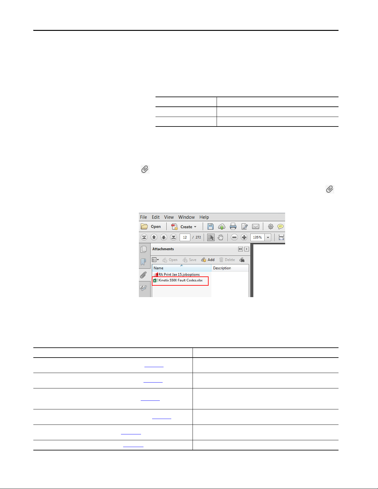
The Microsoft Excel spreadsheet that is attached to this publication contains
fault code descriptions. To use the spreadsheet file, click the Attachments link
, right-click the spreadsheet file, and save the file to your computer.
If the PDF file opens in a browser and you don't see the Attachments link ,
download the PDF file and reopen the file with the Adobe Acrobat Reader
application.
Additional Resources
These documents contain additional information concerning related products
from Rockwell Automation.
Table 1 - Additional Resources
Resource Description
Kinetix Rotary Motion Specifications Technical Data, publication KNX-TD001
Kinetix Linear Motion Specifications Technical Data, publication KNX-TD002
Kinetix Servo Drives Specifications Technical Data, publication KNX-TD003
Kinetix Motion Accessories Specifications Technical Data, publication KNX-TD004
AC Line Filter Installation Instructions, publication 2198-IN003
Shunt Resistor Installation Instructions, publication 2097-IN002 Provides information on how to install and wire Bulletin 2097 shunt resistors.
12 Rockwell Automation Publication 2198-UM001I-EN-P - May 2019
Product specifications for Kinetix VP (Bulletin VPL, VPF, VPH, and VPS), MP-Series™
(Bulletin MPL, MPM, MPF, and MPS), TL-Series™, and HPK-Series™ rotary motors.
Product specifications for MP-Series (Bulletin MPAS ballscrew, MPAR, and MPAI)
and LDAT-Series linear actuators.
Product specifications for Kinetix Integrated Motion over the EtherNet/IP network,
Integrated Motion over sercos interface, EtherNet/IP networking, and component
servo drive families.
Product specifications for Bulletin 2090 motor and interface cables, low-profile
connector kits, drive power components, and other servo drive accessory items.
Provides information on how to install AC line filters designed for Kinetix 5500 and
Kinetix 5700 servo drive systems.
Page 13
Table 1 - Additional Resources (continued)
Resource Description
System Design for Control of Electrical Noise Reference Manual,
publication GMC-RM001
Kinetix Motion Control Selection Guide, publication KNX-SG001
Kinetix 5500 Drive Systems Design Guide, publication KNX-RM009
Rockwell Automation Product Selection
website http://www.rockwellautomation.com/global/support/selection.page
Motion Analyzer System Sizing and Selection Tool
website https://motionanalyzer.rockwellautomation.com/
Product Certifications website, rok.auto/certifications
Motor Nameplate Datasheet Entry for Custom Motor Applications Application Technique,
publication 2198-AT002
Vertical Load and Holding Brake Management Application Technique,
publication MOTION-AT003
Integrated Motion on the EtherNet/IP Network Reference Manual,
publication MOTION-RM003
Integrated Motion on the EtherNet/IP Network Configuration and Startup User Manual,
publication MOTION-UM003
GuardLogix 5570 Controllers User Manual, publication 1756-UM022
GuardLogix 5580 Controllers User Manual, publication 1756-UM543
Compact GuardLogix 5370 Controllers User Manual, publication 1769-UM022
Compact GuardLogix 5380 Controllers User Manual, publication 5069-UM001
GuardLogix 5570 and Compact GuardLogix 5370 Controller Systems Safety Reference
Manual, publication 1756-RM099
GuardLogix 5580 and Compact GuardLogix 5380 Controller Systems Safety Reference
Manual, publication 1756-RM012
ControlFLASH Firmware Upgrade Kit User Manual, publication 1756-UM105
Rockwell Automatio n Industrial Automation Glossary, publication AG-7 .1
Industrial Automation Wiring and Grounding Guidelines, publication 1770-4.1
Information, examples, and techniques designed to minimize system failures
caused by electrical noise.
Overview of Kinetix servo drives, motors, actuators, and motion accessories
designed to help make initial decisions for the motion control products best suited
for your system requirements.
System design guide to select the required (drive specific) drive module, power
accessory, feedback connector kit, and motor cable catalog numbers for your
Kinetix 5500 drive and Kinetix VP motor motion control system.
Online product selection and system configuration tools, including AutoCAD (DXF)
drawings.
Comprehensive motion application sizing tool used for analysis, optimization,
selection, and validation of your Kinetix Motion Control system.
Provides declarations of conformity, certificates, and other certification details.
Provides information on the use of nameplate data entry for custom induction
motors and permanent-magnet motors that are used in applications with
Kinetix 5700 servo drives.
Provides information on vertical loads and how the servo motor holding-brake
option can be used to help keep a load from falling.
Information on the AXIS_CIP_DRIVE attributes and the configuration software
control modes and methods.
Information on how to configure and troubleshoot your ControlLogix® and
CompactLogix™ EtherNet/IP network modules.
Provides information on how to install, configure, program, and use ControlLogix
controllers and GuardLogix® controllers in Studio 5000 Logix Designer® projects.
Provides information on how to install, configure, program, and use CompactLogix
and Compact GuardLogix controllers.
Provides information on how to achieve and maintain Safety Integrity Level (SIL)
and Performance Level (PL) safety application requirements for GuardLogix and
Compact GuardLogix controllers.
Provides information on how to upgrade your drive firmware by using
ControlFLASH ™ software.
A glossary of industrial automation terms and abbreviations.
Provides general guidelines for installing a Rockwell Automation industrial system.
Preface
You can view or download publications at
http://www.rockwellautomation.com/global/literature-library/overview.page
Rockwell Automation Publication 2198-UM001I-EN-P - May 2019 13
.
Page 14

Preface
Notes:
14 Rockwell Automation Publication 2198-UM001I-EN-P - May 2019
Page 15

Chapter 1
Start
Use this chapter to become familiar with the Kinetix® 5500 drive system and
obtain an overview of the installation configurations.
Top ic Pa ge
About the Kinetix 5500 Servo Drive System 15
Drive Hardware and Input Power Configurations 17
Motor Feedback and Feedback-only Configurations 22
Typical Communication Configurations 23
Safe Torque-off Configurations 26
Catalog Number Explanation 29
Agenc y Compliance 30
About the Kinetix 5500 Servo Drive System
Table 2 - Kinetix 5500 Drive System Overview
Drive System
Component
Kinetix 5500
Servo Drives
Kinetix 5500
Capacitor Module
Shared-bus
Connector Kits
Feedba ck
Connector Kit
Hiperface to DSL
Converter Kit
I/O Connector Kits
Connector Sets
Cat. No. Description
2198-Hxxx-ERS
2198-Hxxx-ERS2
2198-CAPMOD-1300
2198-H040-x-x Input wiring connectors and DC bus T-connector for frame 1 and 2 servo drives.
2198-H070-x-x Input wiring connectors and DC bus T-connector for frame 3 servo drives.
2198-KITCON-DSL Replacement feedback connector kit with 2-pin connector plug and grounding plate inside the connector housing.
2198-H2DCK
(series B or later)
2198-KITCON-IOSP Replacement I/O connector kit (spring clamp) for I/O (IOD) connector.
2198-KITCON-IOSC Replacement I/O connector kit (screw terminal) for I/O (IOD) connector.
2198-KITCON-PWR40 Replacement connector set, 40 A, for frame 1 and frame 2 drives.
2198-KITCON-PWR70 Replacement connector set, 70 A, for frame 3 drives.
2198-KITCON-CAP1300 Replacement connector set, 40 A, for capacitor module.
200V-class (single-phase or three-phase) and 400V-class (three-phase) drives operate in standalone and multi-axis shared AC,
shared DC, shared AC/DC, and shared AC/DC hybrid configurations. Modules are zero-stacked from drive-to-drive and use the
shared-bus connection system to extend power in multi-axis configuration s. Safe torque-off via hardwired (STO) connector.
Same power structures as 2198-Hxxx-ERS servo drives with standalone and multi-axis bus-sharing capability. Safe torque-off via
the EtherNet/IP™ network.
Use for energy storage and/or to improve performance in applications producing regenerative energy and requiring shorter duty
cycles (1360 μf). Modules are zero-stacked side-by-side with servo drives and use the shared-bus connection system to extend
power.
Use the 2198-H2DCK Hiperface-to-DSL feedback converter kit with MP-Series™ (Bulletin MPL, MPM, MPF, and MPS) rotary
motors, MP-Series (Bulletin MPAS ballscrew, MPAR, MPAI) linear actuators, and LDAT-Series linear thrusters.
The Kinetix 5500 servo drives are designed to provide a Kinetix Integrated
Motion solution for your drive and motor/actuator application.
Rockwell Automation Publication 2198-UM001I-EN-P - May 2019 15
Page 16

Chapter 1 Start
Table 2 - Kinetix 5500 Drive System Overview (continued)
Drive System
Component
Encoder Output
Module
Logix 5000™
Controller Platform
Studio 5000®
Environment
Rotary Servo
Motors
Linear Actuators
Induction Motors N/A Induction motors with open loop frequency control are also supported.
Cables
AC Line Filters
24V DC Power
Supply
External Shunt
Resistors
Cat. No. Description
2198-ABQE
Bulletin 1769
Bulletin 5069
1756-EN2T module
1756-EN2TR module
1756-EN3TR module
N/A
VPL-Axxxx, VPL-Bxxxx
VPF-Axxxx, VPF-Bxxxx
VPH-Axxxx, VPH-Bxxxx
VPS-Bxxxx
MP-Series
Kinetix VP
MP-Series
LDAT-Series
2090-CSxM1DF-xxAxxx
2090-CSxM1DG-xxAxxx
2090-CFBM7DF-CEAxxx Bulletin 2090 motor feedback cables for MP-Series motors and actuators.
2090-CPxM7DF-xxAxxx Bulletin 2090 motor power/brake cables for MP-Series motors and actuators.
1585J-M8CBJM-x Ethernet cables are available in standard lengths. Shielded cable is recommended.
2198-DB08-F
2198-DB20-F
2198-DB42-F
2198-DBR20-F
2198-DBR40-F
2198-DBR90-F
1606-XLxxx Bulletin 1606 24V DC power supply for control circuitry, digital inputs, safety, and motor brake.
2097-R6 and 2097-R7 Bulletin 2097 external passive shunt resistors for when the internal shunt capability of the drive is exceeded.
The Allen-Bradley® encoder output module is a DIN-rail mounted EtherNet/IP network-based standalone module capable of
outputting encoder pulses to a customer-supplied peripheral device (cameras, for example, used in line-scan vision systems).
Integrated Motion on the EtherNet/IP network in CompactLogix™ 5370, CompactLogix 5380, and CompactLogix 5480 controllers
and Integrated Safety in Compact GuardLogix® 5370 controllers. Linear, device-level ring (DLR), and star topology is supported.
EtherNet/IP network communication modules for use with ControlLogix® 5570, ControlLogix 5580, and GuardLogix 5570
controllers. Linear, device-level ring (DLR), and star topology is supported.
Studio 5000 Logix Designer® application, version 21.00 or later, provides support for programming, commissioning, and
maintaining the CompactLogix and ControlLogix controller families. Version 24.00 or later is required for 2198-Hxxx-ERS2 servo
drives.
Compatible rotary motors include 200V and 400V-class Kinetix VP (Bulletin VPL, VPF, VPH, and VPS).
Compatible rotary motors include 200V and 400V-class MP-Series (Bulletin MPL, MPM, MPF, and MPS) when used with the
Hiperface-to-DSL feedback converter kit.
Compatible linear actuators include 200V and 400V-class Kinetix VP (Bulletin VPAR), MP-Series (Bulletin MPAS ballscrew, MPAR,
and MPAI) and LDAT-Series when used with the Hiperface-to-DSL feedback converter kit.
Bulletin 2090 flying-lead single-cable for motor power, feedback, and 24V DC brake power with Kinetix VP motors. Designed
specifically for Kinetix 5500 servo drives.
Bulletin 2090 flying-lead single cable for motor power, feedback, and 24V DC brake power with Kinetix VP motors and actuators.
Designed with longer leads than 2090-CSxM1DF cables to accommodate Kinetix 5500 or Kinetix 5700 drive families.
Bulletin 2198 three-phase AC line filters are required to meet CE and available for use in all Kinetix 5500 drive systems. Use
2198-DBxx-F filters as field replacements in existing installations. Select 2198-DBRxx-F filters for all new systems and do not
remove the servo drive ground screws.
Bulletin 2198 three-phase AC line filters are required to meet CE and available for use with all Kinetix 5500 drive systems. Select
2198-DBRxx-F filters for all new systems and do not remove the servo drive ground screws.
16 Rockwell Automation Publication 2198-UM001I-EN-P - May 2019
Page 17
Start Chapter 1
Single-phase or
Three- phase
Input Power
Line
Disconnect
Device
Input
Fusin g
2198-Hxxx-ERSx Drive
(front view)
2097-Rx
Shunt Resistor
(optional component)
2198-Hxxx-ERSx Drive
(top view)
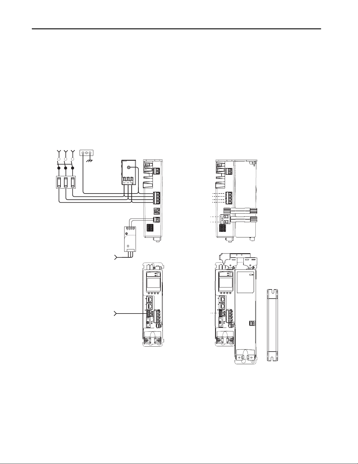
AC Input Power
Bonded Cabinet
Ground Bus
Mains AC and 24V input
wired to standard input
connectors.
2198-DBRxx-F
AC Lin e Filter
(can be required
for CE)
Shared DC (DC common bus)
Shared 24V (control power input)
2198-Hxxx-ERSx Drive (top view)
with 2198-CAPMOD-1300
Capacitor Module
2198-H0x0-x-x shared-bus
connection system for bussharing configurations.
Mains AC input wired to
standard input connector.
Digital Inputs
to Sensors and Control String
1606-XLxxx
24V DC Control, Digital Inputs,
and Motor Brake Power
(customer-supplied)
Drive Hardware and Input Power Configurations
Typical Kinetix 5500 systems include single-phase and three-phase standalone
configurations, three-phase shared AC, shared AC/DC, shared DC, and
shared AC/DC hybrid configurations.
Standalone Configurations
In these examples, a single standalone drive is shown with and without the
Bulletin 2198 capacitor module.
Figure 1 - Typical Kinetix 5500 Standalone Installation
Allen-Bradley
1606-XL
Power Supply
Input
Rockwell Automation Publication 2198-UM001I-EN-P - May 2019 17
Page 18
Chapter 1 Start
1606-XL
Power Supply
Input
Allen-Bradley
Kinetix 5500 Servo Drives (top view)
(2198-H008-ERS drives shown)
2097-Rx
Shunt Resistor
(optional component)
Line
Disconnect
Device
Input
Fusing
Three-phase
Input Power
AC Input Power
Bonded Cabinet
Ground Bus
Kinetix 5500 Servo Drives (front view)
(2198-H008-ERS drives shown)
2198-DBRxx-F
AC Line Filter
(can be required for CE)
Share d AC (mains AC input)
Shared 24V (control power input)
Shared-bus connection system
for bus-sharing configurations.
Digital Inputs
to Sensors and Control String
1606-XLxxx
24V DC Control, Digital Inputs,
and Motor Brake Power
(customer-supplied)
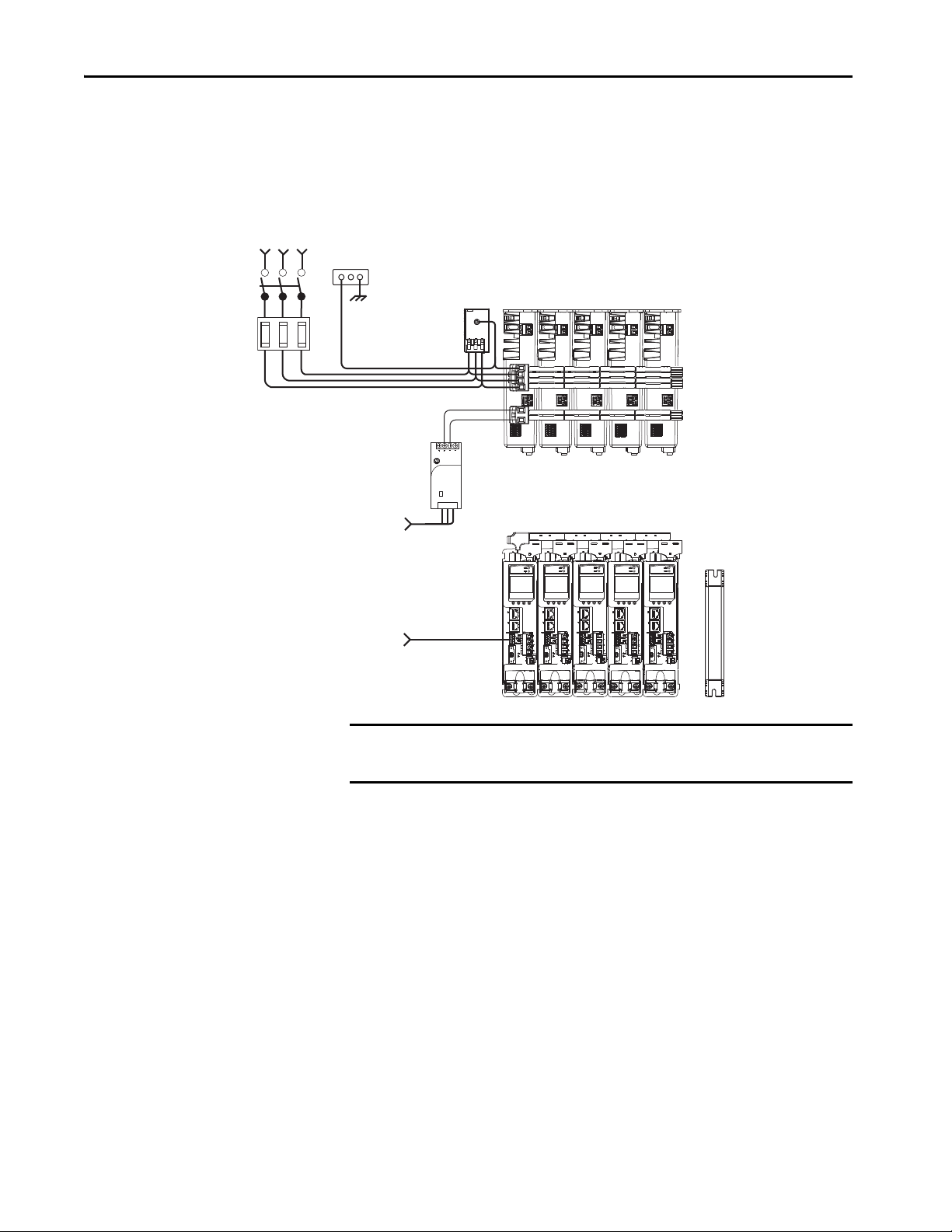
In this example, three-phase AC power and 24V control power is shared in a
multi-axis configuration. All drives must have the same power rating (catalog
number).
Figure 2 - Typical Shared AC Installations
IMPORTANT In shared AC configurations, all drives must have the same power rating.
Shared AC configurations do not support Bulletin 2198 capacitor modules.
18 Rockwell Automation Publication 2198-UM001I-EN-P - May 2019
Page 19
Start Chapter 1
1606-XL
Power Supply
Input
Allen-Bradley
2097-Rx
Shunt Resistor
(optional component)
Line
Disconnect
Device
Input
Fusing
Three-phase
Input Power
AC Input Power
Bonded Cabinet
Ground Bus
2198-DBRxx-F
AC Line Filter
(can be required for CE)
Kinetix 5500 Servo Drives (top view)
(2198-H015-ERS drives shown)
Kinetix 5500 Servo Drives (front view)
(2198-H015-ERS drives shown)
Share d AC (mains AC input)
Shared DC (DC common bus)
Shared 24V (control power input)
2198-CAPMOD-1300 Capacitor Module
(optional component)
Shared-bus connection system for
bus-sharing configurations.
Digital Inputs
to Sensors and Control String
1606-XLxxx
24V DC Control, Digital Inputs,
and Motor Brake Power
(customer-supplied)
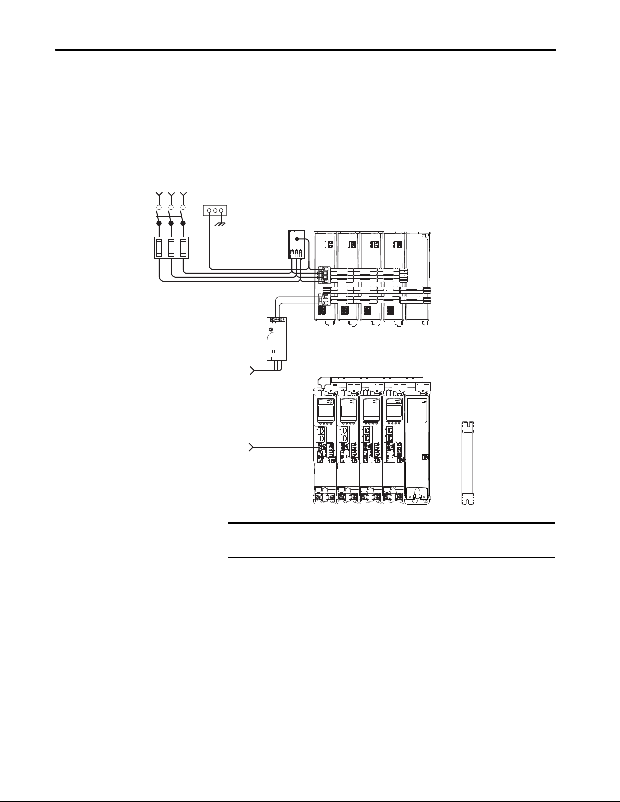
Shared AC/DC Configurations
In this example, three-phase AC input power, 24V control power, and DC-bus
power are shared in a multi-axis configuration. All drives must be the same
power rating (catalog number).
Figure 3 - Typical Shared AC/DC Installations
Rockwell Automation Publication 2198-UM001I-EN-P - May 2019 19
IMPORTANT In shared AC/DC configurations, all drives must have the same power rating
(catalog number).
Page 20
Chapter 1 Start
Kinetix 5500 Servo Drive System (top view)
2097-Rx
Shunt Resistor
(optional component)
Line
Disconnect
Device
Input
Fusing
Three-phase
Input Power
2198-H040-ERS
Common-bus Leader Drive
AC Inp ut Power
Bonded Cabinet
Ground Bus
Kinetix 5500 Servo Drive System (front view)
2198-H008-ERS
Common-bus
Follower Drives
2198-DBRxx-F
AC Line Filt er
(can be required for CE)
Shared DC (DC common bus)
Shared 24V (control power input)
2198-CAPMOD-1300 Capacitor Module
(optional component)
Shared-bus connection system
for bus-sharing configurations.
Digital Inputs
to Sensors and Control String
1606-XLxxx
24V DC Control, Digital Inputs,
and Motor Brake Power
(customer-supplied)
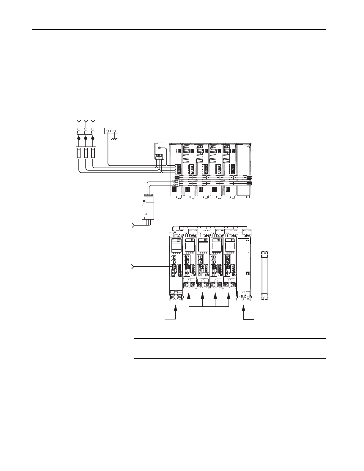
Shared DC Common-bus Configurations
In this multi-axis example, the common-bus leader (sourcing) drive receives
three-phase AC input power and supplies DC power to common-bus follower
(sinking) drives. The common-bus leader-drive power rating is greater than or
equal to the power rating of each follower drive.
Figure 4 - Typical Shared DC Common-bus Installations
Allen-Bradley
1606-XL
Power Supply
Input
(
IMPORTANT In shared DC common-bus configurations, the leader drive power rating
must be greater than or equal to the power rating of the follower drives.
20 Rockwell Automation Publication 2198-UM001I-EN-P - May 2019
Page 21
Start Chapter 1
1606-XL
Power Supply
Input
Allen-Bradley
Kinetix 5500 Servo Drive System (top view)
2097-Rx
Shunt Resistor
(optional component)
Line
Disconnect
Device
Input
Fusing
Three-phase
Input Power
Digital Inputs
to Sensors and Control String
2198-H040-ERS
Common-bus (converter)
Leader Drives
1606-XLxxx
24V DC Control, Digital Inputs,
and Motor Brake Power
(customer-supplied)
AC Input Po wer
Bonded Cabinet
Ground Bus
Kinetix 5500 Servo Drive System (front view)
2198-H008-ERS
Common-bus (inverter)
Follower Drives
2198-DBRxx-F
AC Line Filter
(can be required for CE)
Share d AC (mains AC input)
Shared DC (DC common bus)
Shared 24V (control power input)
Shared-bus connection system for
bus-sharing configurations.
2198-CAPMOD-1300 Capacitor Module
(optional component)
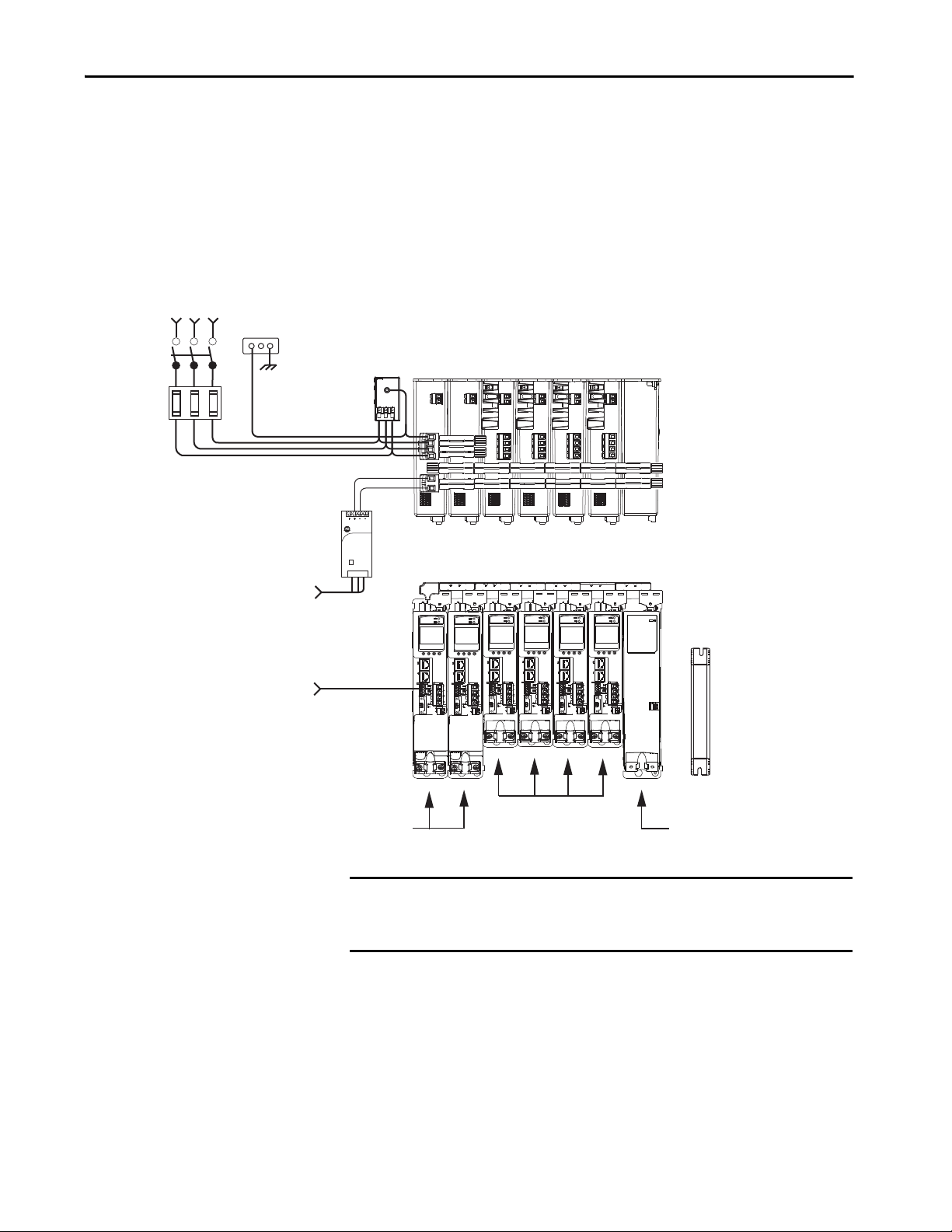
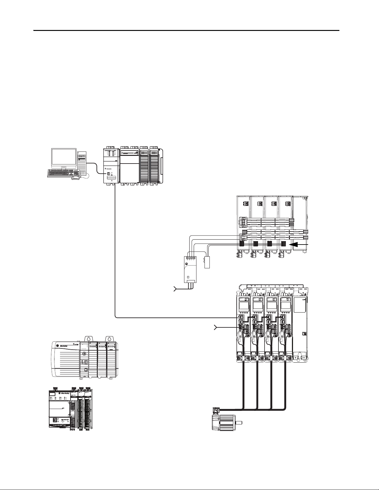
Shared AC/DC Hybrid Configuration
In this multi-axis example, three-phase AC input power is supplied to two
converter drives. The converter drive ratings must be the same, and greater
than or equal to the power ratings of the inverter drives. This parallel converter
configuration increases the DC-bus power supplied to the inverter drives.
Figure 5 - Typical Shared AC/DC Bus Hybrid Installations
IMPORTANT In shared AC/DC hybrid configuration, the converter drives must have the
same power rating and must be greater than or equal to the power ratings
of the inverter drives.
Rockwell Automation Publication 2198-UM001I-EN-P - May 2019 21
Page 22
Chapter 1 Start
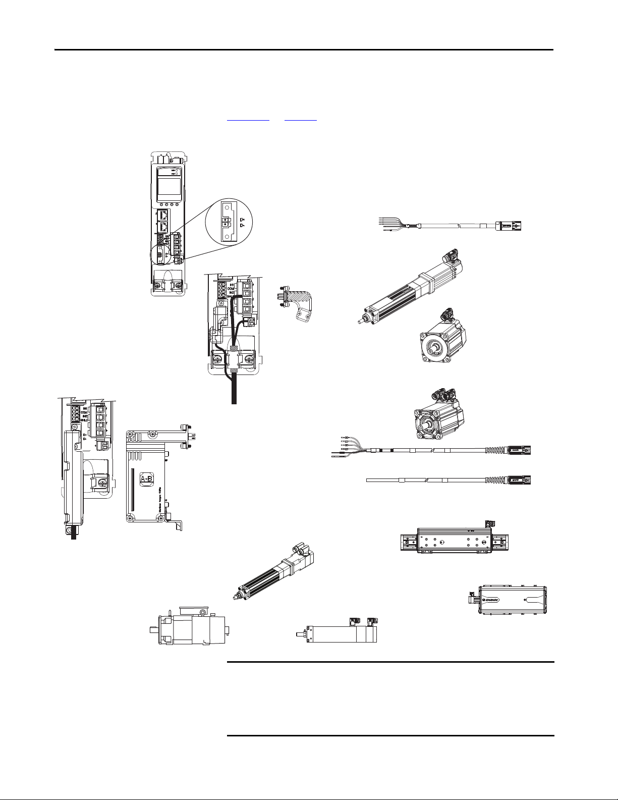
2090-CSBM1DF or 2090-CSBM1DG
Single Motor Cables
2198-KITCON-DSL Connector Kit
• Accepts DSL motor feedback from Kinetix VP
(Bulletin VPL, VPF, VPH, VPS) rotary motors
and Kinetix VP electric cylinders.
• Feedback-only (DSL)
Bulletin 2090 Motor Power and Feedback Cables
MP-Series Linear Actuators
(MPAR-B3xxxx electric cylinder is shown)
MP-Series Rotary Motors
(MPL-Bxxxx motor is shown)
LDAT-Sxxxxxx-xDx
Linear Thrusters
2198-H2DCK Converter Kit
Converts 15-pin Hiperface feedback into 2-pin DSL feedback for:
• MP-Series rotary motors and linear actuators
• LDAT-Series linear thrusters
• Feedback-only (absolute single-turn/multi-turn Hiperface)
2-pin Motor Feedback
(MF) Connector
2198-Hxxx-ERSx Drive
(front view)
MP-Series Linear Actuators
(MPAS-B9xxx ballscrew linear stage is shown)
Kinetix VP Rotary Motors
(VPL-Bxxxx motor is shown)
MP-Series Linear Actuators
(MPAI-B3xxxx heavy-duty electric c ylinder is shown)
Induction Rotary Motors
(no feedback, V/Hz)
Kinetix VP Electric Cylinders
(Bulletin VPAR)
Motor Feedback and Feedback-only Configurations
Feedback connections are made at the 2-pin motor feedback (MF) connector.
These examples illustrate how you can use the Bulletin 2198 connector kits for
making these connections. To see motor power and brake connections, refer to
Chapter 5
Figure 6 - Feedback Configuration Examples
on page 73.
IMPORTANT In 2198-H2DCK converter kit applications, you can replace the 2090-
CPxM7DF power/brake cable with a 2090-CSBM1DF single motor cable, and
reuse the 2090-CFBM7DF feedback cable. This increases the maximum cable
length for 18 and 14 AWG single cables to 50 m (164 ft). 2090-CSxM1DF-
10Axxx (10 AWG) cables do not support this 50 m (164 ft) option.
22 Rockwell Automation Publication 2198-UM001I-EN-P - May 2019
Page 23

Start Chapter 1
2198-ABQE
Encoder Output Module
Compac tLogix 5370 Controller
Studio 5000 Logix Designer
Application
1585J-M8CBJM-x
Ethernet (shielded) Cable
1734-AENTR POINT I/O™
EtherNet/IP Adapter
CompactLogix Controller Programming Network
PanelView™ Plus
Display Terminal
1585J-M8CBJM-OM15
0.15 m (6 in.) Ethernet cable
for drive-to-drive connections.
Kinetix 5500 Servo Drive System
842E-CM Integrated
Motion Encoder
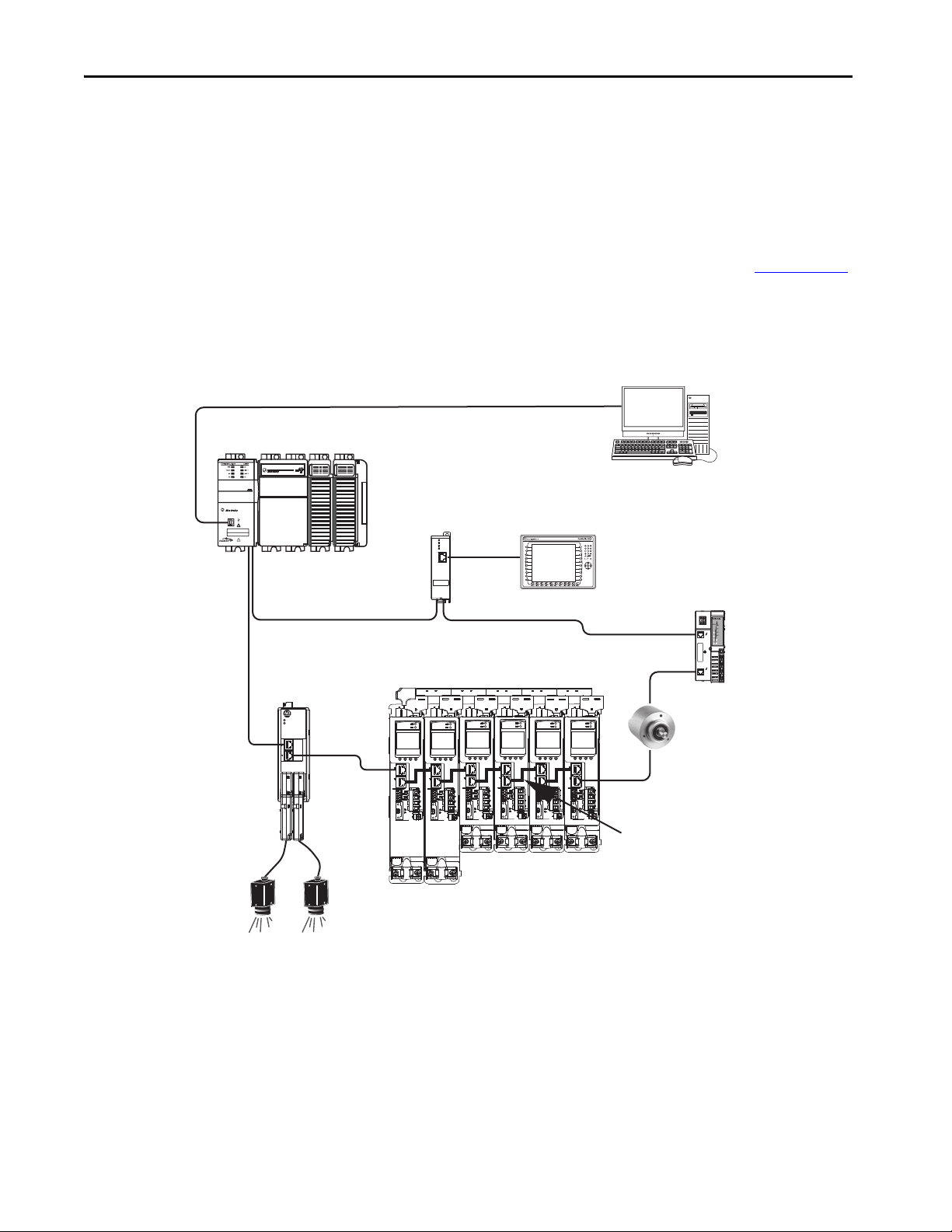
Typical Communication Configurations
The Kinetix 5500 drives support any Ethernet topology including linear, ring,
and star by using ControlLogix, GuardLogix, or CompactLogix controllers.
These examples feature the CompactLogix 5370 programmable automation
controllers (Bulletin 1769) with support for Integrated Motion over the
EtherNet/IP network.
Refer to CompactLogix Controllers Specifications Technical Data, publication
1769-TD005
, for more information on CompactLogix 5370 L1, L2, and L3
controllers.
Linear Topology
In this example, all devices are connected in linear topology. The Kinetix 5500
drives include dual-port connectivity, however, if any device becomes
disconnected, all devices downstream of that device lose communication.
Devices without dual ports must include the 1783-ETAP module or be
connected at the end of the line.
Figure 7 - Kinetix 5500 Linear Communication Installation
00:00:BC:2E:69:F6
1 (Front)
2 (Rear)
MOD
NET
OUTPUT-A OUTPUT-B
1734-AENTR
02
0
POINT I O
Module
Status
Network
Activity
Network
Status
Point Bus
Status
Link 1
Activity/
System
Status
Power
Field
Power
Link 2
Activity/
Status
Rockwell Automation Publication 2198-UM001I-EN-P - May 2019 23
Page 24
Chapter 1 Start
1 (Front)
2 (Rear)
00:00:BC:2E:69:F6
02
0
1734-AENTR
Module
Status
Network
Activity
Network
Status
Point Bus
Status
System
Power
Field
Power
POINT I O
Link 1
Activity/
Status
Link 2
Activity/
Status
MOD
NET
OUTPUT-A OUTPUT-B
2198-ABQE
Encoder Output Module
1734-AENTR POINT I/O
EtherNet/IP Adapter
CompactLogix Controller Programming Network
1783-ETAP
Module
1585J-M8CBJM-OM15
0.15 m (6 in.) Ethernet cable
for drive-to-drive connections.
Panel View Plus
Display Terminal
Kinetix 5500 Servo Drive System
Compac tLogix 5370 Controller
Studio 5000 Logix Designer
Application
1585J-M8CBJM-x Ethernet
(shielded) Cable
842E-CM Integrated
Motion Encoder
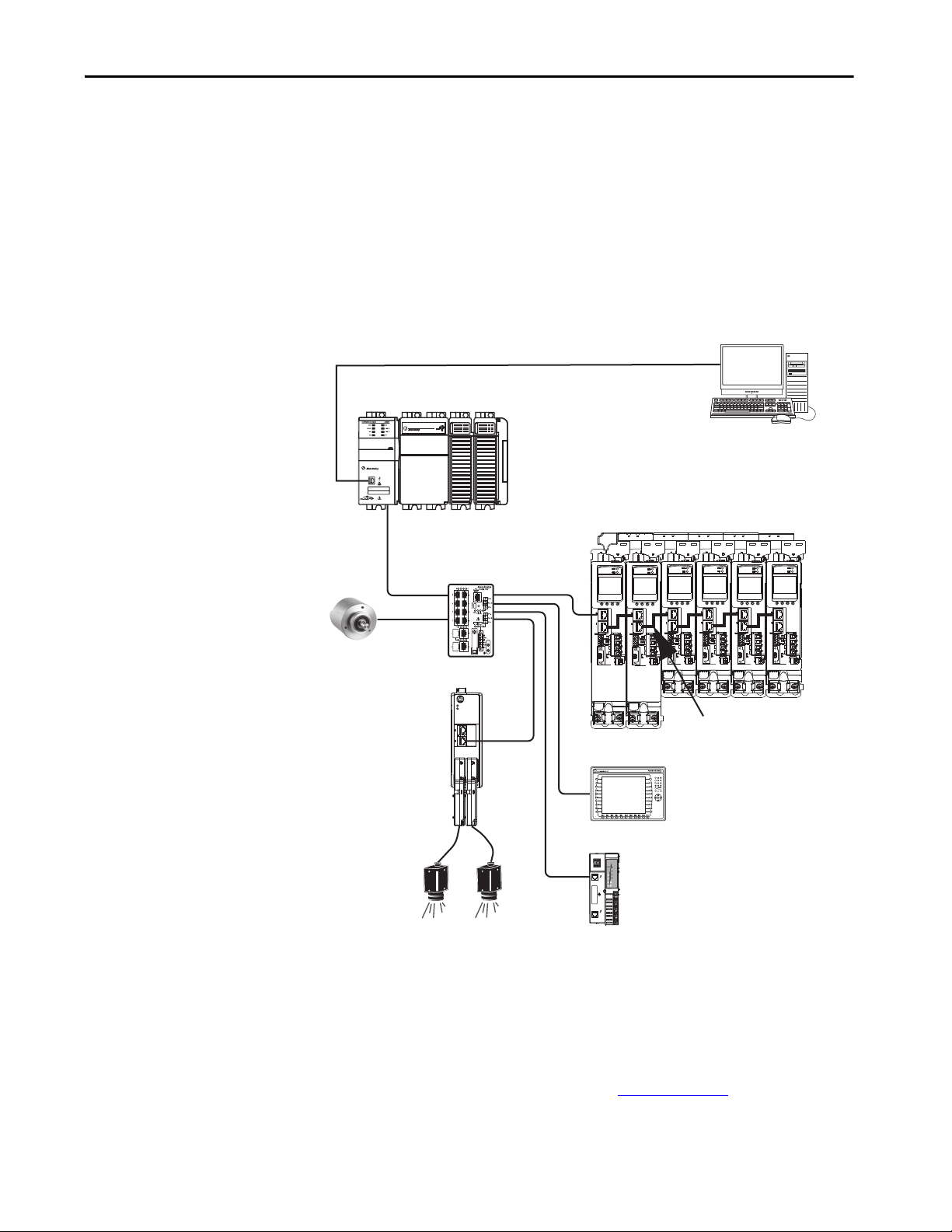
Ring Topology
In this example, the devices are connected by using ring topology. If only one
device in the ring is disconnected, the rest of the devices continue to
communicate. For ring topology to work correctly, a device level ring (DLR)
supervisor is required (for example, the Bulletin 1783 ETAP device). DLR is
an ODVA standard. For more information, refer to the EtherNet/IP
Embedded Switch Technology Application Guide, publication ENET-AP005
Devices without dual ports, for example the display terminal, require a
1783-ETAP module to complete the network ring.
Figure 8 - Kinetix 5500 Ring Communication Installation
.
24 Rockwell Automation Publication 2198-UM001I-EN-P - May 2019
Page 25
Start Chapter 1
2198-ABQE
Encoder Output Module
1585J-M8CBJM-x
Ethernet (shielded) Cable
1734-AENTR POINT I/O
EtherNet/IP Adap ter
CompactLogix Controller Programming Network
PanelView Plus
Display Terminal
1783-BMS
Stratix® 5700
Switch
1585J-M8CBJM-OM15
0.15 m (6 in.) Ethernet cable
for drive-to-drive connections.
Kinetix 5500 Servo Drive System
CompactLogix 53 70 Controller
Studio 5000 Logix Designer
Application
842E-CM Integrated
Motion Encoder
Star Topology
In this example, the devices are connected by using star topology. Each device is
connected directly to the switch.
Kinetix 5500 drives have dual ports, so linear topology is maintained from
drive-to-drive, but Kinetix 5500 drives and other devices operate
independently. The loss of one device does not impact the operation of other
devices.
Figure 9 - Kinetix 5500 Star Communication Installation
00:00:BC:2E:69:F6
1 (Front)
2 (Rear)
MOD
NET
OUTPUT-A OUTPUT-B
You can use the 842E-CM integrated motion encoder for applications
requiring an external encoder for gearing or camming to the Kineitx 5700
drive. By providing auxiliary feedback directly through the EtherNet/IP
network, the 842E-CM encoder helps eliminate the need for point-to-point
wiring while letting customers use the encoder in a variety of network
topologies. For more information, see the 842E-CM Integrated Motion on
EtherNet/IP Product Profile, publication 842ECM-PP001
.
Rockwell Automation Publication 2198-UM001I-EN-P - May 2019 25
Page 26
Chapter 1 Start
1 (Front)
2 (Rear)
00:00:BC:2E:69:F6
1606-XL
Power Supply
Input
Allen-Bradley
OKFORCESDRUN
Logix5585
LINK
NET
TM
SAFETY ON
0000
DC INPUT
AC OUTPUT
DC INPUT
1585J-M8CBJM-x
Ethernet (shielded) Cable
Studio 5000 Logix Designer
Application
(version 21.0 or later)
AC Inp ut Power
Safety
Device
2198-Hxxx-ERS Servo Drives
(front view)
Digital Inputs to Sensors and Control String
1606-XLxxx
24V DC Control, Digital Inputs,
and Motor Brake Power
(customer-supplied)
Kinetix VP
Servo Motors
Module Definition
Configured with
Motion-only
Connection
Safe Torque-off
(STO) Connectors
Any Logix 5000 Controller
(CompactLogix 5370 controller is shown)
2198-Hxxx-ERS Servo Drives
(top view)
ControlLogix 5570 Controllers or
GuardLogix 5570 Safety Controllers
ControlLogix 5580 Controllers or
GuardLogix 5580 Safety Controllers
CompactLogix 53 70 Controllers or
Compact GuardLogix 5370 Safety Controllers
CompactLogix 5380 or 5480 Controllers or
Compact GuardLogix 5380 Safety Controllers
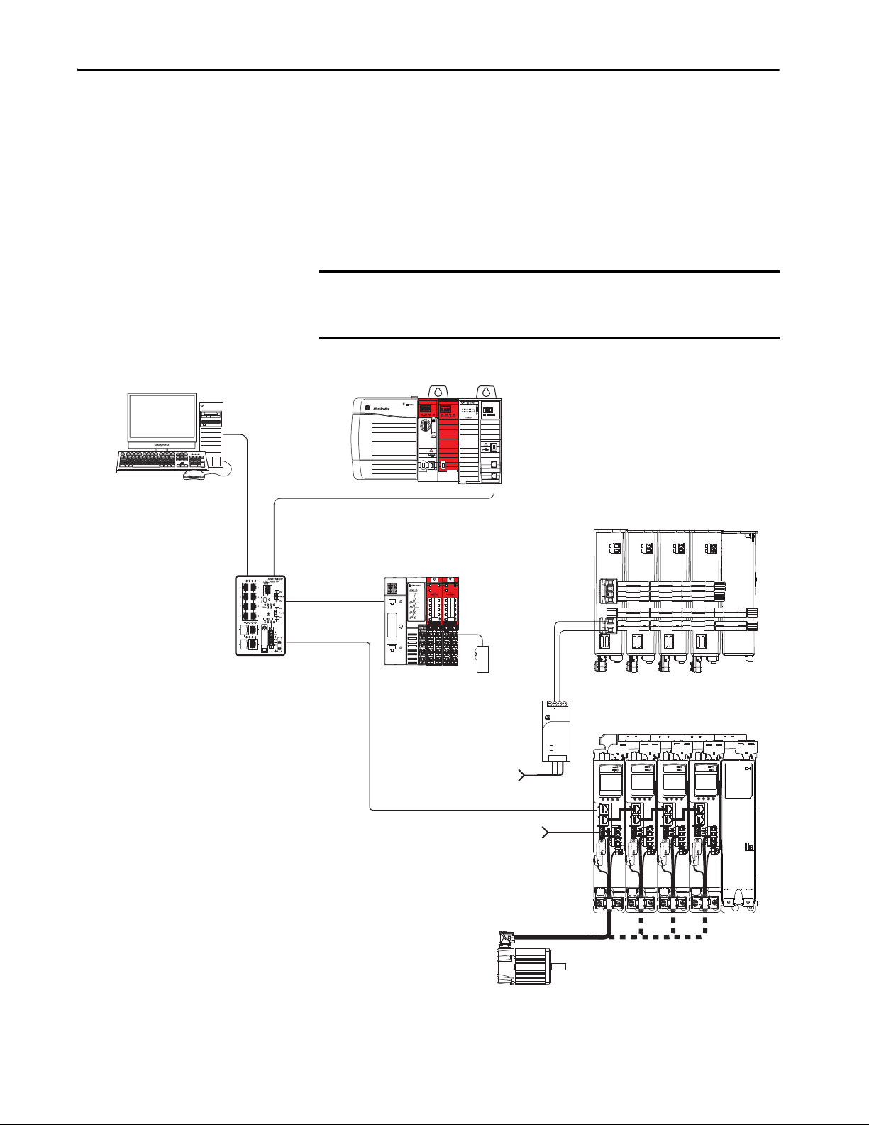
Safe Torque-off Configurations
Kinetix 5500 servo drives are available with safe torque-off via hardwired
connections or integrated over the EtherNet/IP network. These examples
illustrate the safe torque-off configuration options.
Hardwired Safety Configuration
The 2198-Hxxx-ERS drives use the safe torque-off (STO) connector for
wiring external safety devices and cascading hardwired safety connections from
one drive to another.
Figure 10 - Safe Torque-off (hardwired) Configuration
26 Rockwell Automation Publication 2198-UM001I-EN-P - May 2019
Page 27
Start Chapter 1
1606-XL
Power Supply
Input
Allen-Bradley
LNK1LNK2NET OK
EtherNet/IP
1
2
1585J-M8CBJM-x
Ethernet (shielded) Cable
Studio 5000 Logix Designer
Application
(version 24.0 or later)
AC Input Po wer
2198-Hxxx-ERS2 Servo Drives
(top view)
2198-Hxxx-ERS2 Servo Drives
(front view)
Digital Inputs to Sensors and Control String
1606-XLxxx
24V DC Control, Digital Inputs,
and Motor Brake Power
(customer-supplied)
Kinetix VP
Servo Motors
1783-BMS
Stratix 5700
Switch
Module Definition
Configured with
Motion and Safety
Connections
1734-AENTR
POINT Guard I/O™
EtherNet/IP Adapter
Safety
Device
Motion and Safety Connections to the Drive
Compact GuardLogix 5370 Controller,
Compact GuardLogix 5380 Safety Controller or
GuardLogix 5570 Controller,
GuardLogix 5580 Safety Controller
(GuardLogix 5570 Safety Controller is shown)
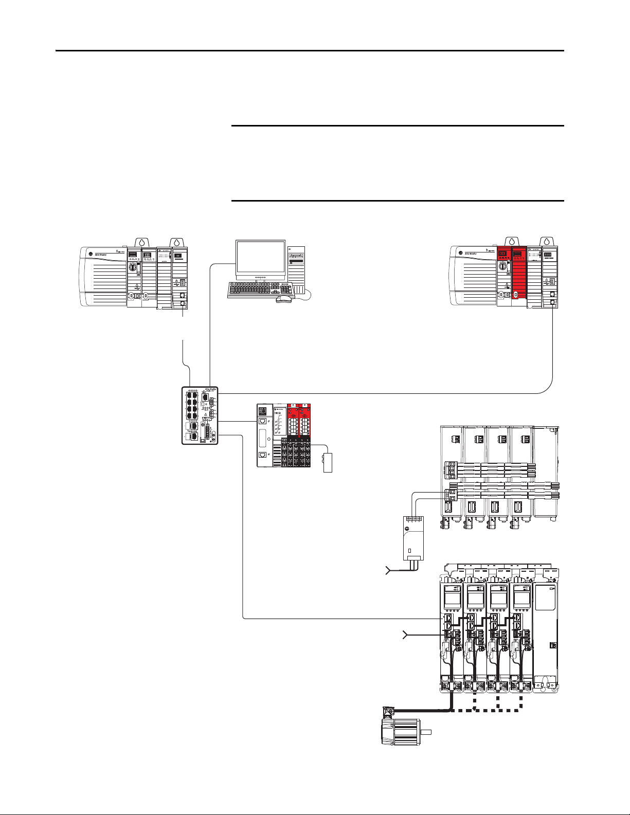
Integrated Safety Configurations
The GuardLogix 5570 or Compact GuardLogix 5370 safety controller issues
the safe torque-off (STO) command over the EtherNet/IP network and the
2198-Hxxx-ERS2 integrated safety drive executes the command.
In this example, a single GuardLogix safety controller makes a Motion and
Safety connection with the 2198-Hxxx-ERS2 integrated safety drives.
IMPORTANT If only one controller is used in an application with Motion and Safety
connections, the controller must be a GuardLogix 5570 or Compact
GuardLogix 5370 safety controller.
Figure 11 - Motion and Safety Configuration (single controller)
Rockwell Automation Publication 2198-UM001I-EN-P - May 2019 27
Page 28
Chapter 1 Start
1585J-M8CBJM-x
Ethernet (shielded) Cable
Studio 5000 Logix Designer
Application
(version 24.0 or later)
AC Input Po wer
2198-Hxxx-ERS2 Servo Drives
(top view)
2198-Hxxx-ERS2 Servo Drives
(front view)
Digital Inputs to Sensors and Control String
1606-XLxxx
24V DC Control, Digital Inputs,
and Motor Brake Power
(customer-supplied)
Kinetix VP
Servo Motors
1734-AENTR
POINT Guard I/O
EtherNet/IP Adapter
1783-BMS
Stratix 5700
Switch
Motion Program
Module Definition
Configured with
Motion only
Connection
Safety Program
Module Definition
Config ured with S afety
only Connection
Safety
Device
Motion and Safety Connections to the Drive
Any Logix 5000 Controller
(ControlLogix 5570 controller is shown)
Compact GuardLogix 5370 Controller,
Compact GuardLogix 5380 Safety Controller or
GuardLogix 5570 Controller,
GuardLogix 5580 Safety Controller
(GuardLogix 5570 Safety Controller is shown)
In this example, a non-safety controller makes the Motion-only connection
and a separate GuardLogix safety controller makes the Safety-only connection
with 2198-Hxxx-ERS2 integrated safety drives.
IMPORTANT If two controllers are used in an application with Motion-only and
Safety-only connections, the Safety-only connection must be a
GuardLogix 5570 or Compact GuardLogix 5370 safety controller and the
Motion-only connection must be a ControlLogix 5570 or
CompactLogix 5370 controller.
Figure 12 - Motion and Safety Configuration (multi-controller)
EtherNet/IP
LNK1LNK2NET OK
2
1
Allen-Bradley
1606-XL
Power Supply
Input
LNK1LNK2NET OK
EtherNet/IP
2
1
28 Rockwell Automation Publication 2198-UM001I-EN-P - May 2019
Page 29

Start Chapter 1
Catalog Number Explanation
Drive Cat. No.
(hardwired STO)
2198-H003-ERS 2198-H003-ERS2
2198-H008-ERS 2198-H008-ERS2
2198-H015-ERS 2198-H015-ERS2
2198-H025-ERS 2198-H025-ERS2
2198-H040-ERS 2198-H040-ERS2
2198-H070-ERS 2198-H070-ERS2 3
Capacitor Module
Cat. No.
2198-CAPMOD-1300 2 650V DC, nom 1360 μF, min
Kinetix 5500 drive catalog numbers and performance descriptions.
Table 3 - Kinetix 5500 Servo Drive Catalog Numbers
Drive Cat. No.
(integrated STO)
Frame Size Input Voltage
1
2
195…264V rms, single-phase
195…264V rms, three-phase
324…528V rms, three-phase
195…264V rms, three-phase
324…528V rms, three-phase
Table 4 - Capacitor Module Catalog Number
Frame Size Rated Voltage Capacitance
Continuous Output
Power
kW
0.2 kW
0.3 kW
0.6 kW
0.5 kW
0.8 kW
1.6 kW
1.0 kW
1.5 KW
3.2 kW
2.4 kW
5.1 kW
4.0 kW
8.3 kW
7.0 kW
14.6 kW
Continuous Output
Current
A 0-pk
1.4
3.5
7.1
11.3
18.4
32.5
Table 5 - Shared-bus Connector Kit Catalog Numbers
Kit Cat. No. Frame Size Application Description
2198-H040-ADP-IN Frame 1 or 2 First drive
2198-H040-A-T
2198-H040-D-T DC sharing only DC bus T-connector
2198-H040-P-T Control power sharing only Control power T-connector
2198-H040-AD-T AC and DC-bus sharing AC and DC bus T-connectors
2198-H040-AP-T AC and control power sharing AC and control power T-connectors
2198-H040-DP-T DC and control power sharing DC and control power T-connectors
2198-H040-ADP-T AC, DC, and control power sharing AC, DC, and control power T-connectors
2198-H070-ADP-IN
2198-H070-A-T
2198-H070-D-T DC sharing only DC bus T-connector
2198-H070-P-T Control power sharing only Control power T-connector
2198-H070-AD-T AC and DC-bus sharing AC and DC bus T-connectors
2198-H070-AP-T AC and control power sharing AC and control power T-connectors
2198-H070-DP-T DC and control power sharing DC and control power T-connectors
2198-H070-ADP-T AC, DC, and control power sharing AC, DC, and control power T-connectors
Next drive is…
Frame 1 drives:
2198-H003-ERSx
2198-H008-ERSx
Frame 2 drives:
2198-H015-ERSx
2198-H025-ERSx
2198-H040-ERSx
Frame 3 drive:
2198-H070-ERSx
Next drive is…
Frame 3 drives:
2198-H070-ERSx
AC sharing only AC bus T-connector
First drive
AC sharing only AC bus T-connector
• Mains AC input wiring connector
• 24V DC input wiring connector
•DC bus T-connector
• Mains AC input wiring connector
• 24V DC input wiring connector
•DC bus T-connector
Rockwell Automation Publication 2198-UM001I-EN-P - May 2019 29
Page 30
Chapter 1 Start
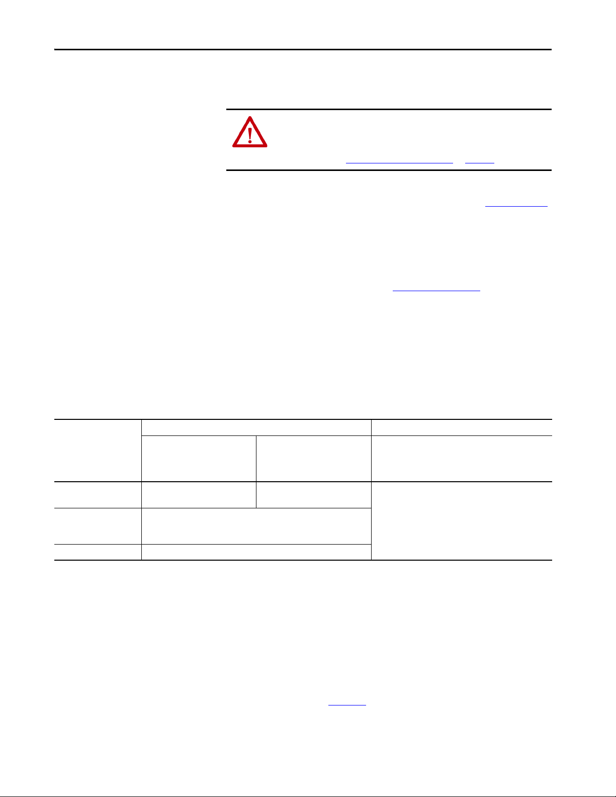
Agency Compliance
If this product is installed within the European Union and has the CE mark,
the following regulations apply.
ATT EN TI ON : Meeting CE requires a grounded system, and the method of
grounding the AC line filter and drive must match. Failure to do this renders
the filter ineffective and can cause damage to the filter. For grounding
examples, refer to Grounded Power Configurations
on page 75.
For more information on electrical noise reduction, refer to the System Design
for Control of Electrical Noise Reference Manual, publication GMC-RM001
To meet CE requirements, these requirements apply:
• Install an AC line filter (catalog number 2198-DBRxx-F) for input
power as close to the Kinetix 5500 drive as possible.
• Bond drive, capacitor module, and line filter grounding screws by using a
braided ground strap as shown in Figure 43 on page 80
.
• Use Bulletin 2090 single motor cables with Kinetix VP servo motors
and actuators. Use Bulletin 2090 motor power/brake and feedback
cables for other compatible Allen-Bradley motors and actuators.
• Combined motor cable length for all axes on the same DC bus must not
exceed 250 m (820 ft). Drive-to-motor cables must not exceed 50 m
(164 ft); however, use of continuous-flex cable and 2198-H2DCK
converter kit limits the maximum length.
.
Table 6 - Drive-to-Motor Maximum Cable Length
Kinetix VP Servo Motors Other Compatible Rotary Motors/Linear Actuators
Kinetix 5500 Servo Drive
Cat. No.
2198-H003-ERSx
2198-H008-ERSx
2198-H015-ERSx
2198-H025-ERSx
2198-H040-ERSx
2198-H070-ERSx 50 (164)
(1) When using 2090-CSBM1E1 cable in your continuous-flex application, the maximum cable length including the standard (non-flex) cable back to the drive, is 30 m (98.4 ft)
(2) Requires use of the 2198-H2DCK Hiperface-to-DSL (series B or later) feedback converter kit.
(3) The 20 m (65.6 ft) limitation is attributed to the 2090-CPxM7DF power/brake cable. In 2198-H2DCK converter kit applications, you can replace the 2090-CPxM7DF power/brake cable with a
2090-CSBM1DF or 2090-CSBM1DG single motor cable (and reuse the 2090-CFBM7DF feedback cable) to increase the maximum cable length t o 50 m (164 f t). This app lies to only 1 8 and 14 AWG sing le
cables. 2090-CSxM1Dx-10Axxx (10 AWG/M40 connector) single cables are not compatible with 2090-CPBM7DF-10Axxx (10 AWG/M40 connector) power/brake cables.
Standard (non-flex) Cables
Cat. No. 2090-CSxM1DF/DG-xxAAxx
m (ft)
50 (164) 30 (98.4)
50 (164)
Continuous-flex Cables
Cat. No. 2090-CSBM1DF/DG-xxAFxx
Cat. No. 2090-CSBM1E1-xxAFxx
m (ft)
(1)
Bulletin 2090 Motor/Actuator Cables
Cat. No. 2090-CxxM7DF
m (ft)
20 (65.6)
(3)
• Install the Kinetix 5500 system inside an approved enclosure. Run input
power wiring in conduit (grounded to the enclosure) outside of the
enclosure. Separate signal and power cables.
• Segregate input power wiring from control wiring and motor cables.
(2)
Refer to Appendix A on page 193
for input power wiring and drive/motor
interconnect diagrams.
30 Rockwell Automation Publication 2198-UM001I-EN-P - May 2019
Page 31
Chapter 2
Plan the Kinetix 5500 Drive System Installation
This chapter describes system installation guidelines used in preparation for
mounting your Kinetix® 5500 drive components.
Top ic Pa ge
System Design Guidelines 32
Electrical Noise Reduction 41
ATT EN TI ON : Plan the installation of your system so that you can perform all
cutting, drilling, tapping, and welding with the system removed from the
enclosure. Because the system is of the open type construction, be careful to
keep metal debris from falling into it. Metal debris or other foreign matter
can become lodged in the circuitry and result in damage to the components.
Rockwell Automation Publication 2198-UM001I-EN-P - May 2019 31
Page 32

Chapter 2 Plan the Kinetix 5500 Drive System Installation
System Design Guidelines
Use the information in this section when designing your enclosure and
planning to mount your system components on the panel.
For on-line product selection and system configuration tools, including
AutoCAD (DXF) drawings of the product, refer to
https://www.rockwellautomation.com/global/support/selection.page
System Mounting Requirements
• To comply with UL and CE requirements, the Kinetix 5500 drive
systems must be enclosed in a grounded conductive enclosure offering
protection as defined in standard IEC 60529 to IP20 such that they are
not accessible to an operator or unskilled person. A NEMA 4X
enclosure exceeds these requirements providing protection to IP66.
To maintain the functional safety rating of the Kinetix 5700 drive
system, this enclosure must be appropriate for the environmental
conditions of the industrial location and provide a protection class of
IP54 or higher.
• The panel that you install inside the enclosure for mounting your system
components must be on a flat, rigid, vertical surface that won’t be
subjected to shock, vibration, moisture, oil mist, dust, or corrosive
vapors in accordance with pollution degree 2 (IEC 61800-5-1) because
the product is rated to protection class IP20 (IEC 60529).
• Size the drive enclosure so as not to exceed the maximum ambient
temperature rating. Consider heat dissipation specifications for all drive
components.
• Combined motor power cable length for all axes on the same DC bus
must not exceed 250 m (820 ft). Drive-to-motor cables must not exceed
50 m (164 ft), however use of continuous-flex cable and 2198-H2DCK
converter kit limits the maximum length. Refer to Ta b l e 6
for specifications by frame size.
on page 30
.
IMPORTANT System performance was tested at these cable length
specifications. These limitations also apply when meeting CE
requirements.
• Use high-frequency (HF) bonding techniques to connect the modules,
enclosure, machine frame, and motor housing, and to provide a lowimpedance return path for high-frequency (HF) energy and reduce
electrical noise.
Bond drive, capacitor module, and line filter grounding screws by using a
braided ground strap as shown in Figure 43 on page 80
Refer to the System Design for Control of Electrical Noise Reference Manual,
publication GMC-RM001
reduction.
32 Rockwell Automation Publication 2198-UM001I-EN-P - May 2019
, to better understand the concept of electrical noise
.
Page 33

Plan the Kinetix 5500 Drive System Installation Chapter 2
AC Line Filter Selection
An AC line filter is required to meet CE requirements. Install an AC line filter
for input power as close to the 2198-Hxxx-ERSx drive as possible.
IMPORTANT AC line filters are only recommended with grounded WYE power
configurations. For facility power configuration examples, see Determine the
Input Power Configuration on page 75.
Table 7 - AC Line Filter Selection
Kinetix Drive Module
Cat. No.
2198-H003-ERSx
2198-H008-ERSx
2198-H015-ERSx
2198-H025-ERSx
2198-H040-ERSx
2198-H070-ERSx
AC Line Filter
Cat. No.
2198-DB08-F
• 2198-DBR20-F or
• 2198-DB20-F
• 2198-DBR40-F or
• 2198-DB42-F
IMPORTANT Use 2198-DBxx-F line filters only as field replacements in existing
installations. Select 2198-DBRxx-F line filters for all new systems or to
replace existing 2198-DBxx-F line filters. This does not apply to
2198-DB08-F line filters.
Table 8 - AC Line Filter Selection for Shared AC and Shared AC/DC and Hybrid Multi-axis Systems
Kinetix 5500 Drives
Cat. No.
2198-H003-ERSx 240/480V 2198-DBR20-F
2198-H008-ERSx 240/480V 2198-DBR20-F
2198-H015-ERSx 240/480V 2198-DBR20-F –
2198-H025-ERSx 240/480V 2198-DBR40-F –
2198-H040-ERSx 240/480V 2198-DBR40-F 2198-DBR90-F –
2198-H070-ERSx 240/480V 2198-DBR90-F –
Drive Voltage,
(three-phase)
nom
2
Axes
AC Line Filter Cat. No.
3
Axes4 Axes5 Axes6 Axes7 Axes8 Axes
Rockwell Automation Publication 2198-UM001I-EN-P - May 2019 33
Page 34

Chapter 2 Plan the Kinetix 5500 Drive System Installation
Transformer Selection
The servo drive does not require an isolation transformer for three-phase input
power. However, a transformer can be required to match the voltage
requirements of the drive to the available service.
To size a transformer for the main AC power inputs, refer to the Kinetix 5500
power specifications in the Kinetix Servo Drives Technical Data, publication
KNX-TD003
IMPORTANT When using an autotransformer, make sure that the phase to neutral/
IMPORTANT Use a form factor of 1.5 for three-phase power (where form factor is used to
IMPORTANT A line reactor must be used if the source transformer is greater than
.
ground voltage does not exceed the input voltage ratings of the drive.
compensate for transformer, drive module, and motor losses, and to account
for utilization in the intermittent operating area of the torque speed curve).
150 KVA, max and 3% impedance, min.
EXAMPLE Sizing a transformer to the voltage requirements of this drive:
2198-H040-ERSx = 8.4 kW = 12.6 KVA transformer.
Circuit Breaker/Fuse Selection
The Kinetix 5500 drives use internal solid-state motor short-circuit protection
and, when protected by suitable branch circuit protection, are rated for use on
a circuit capable of delivering up to 200,000 A (fuses) and 65,000 A (circuit
breakers).
Refer to Power Wiring Examples
ATT EN TI ON : Do not use circuit protection devices on the output of an AC
drive as an isolating disconnect switch or motor overload device. These
devices are designed to operate on sine wave voltage and the drive’s PWM
waveform does not allow it to operate properly. As a result, damage to the
device occurs.
, on page 194, for the wiring diagram.
34 Rockwell Automation Publication 2198-UM001I-EN-P - May 2019
Page 35

Plan the Kinetix 5500 Drive System Installation Chapter 2
Standalone Drive Systems
Kinetix 5500 Drives UL Applications IEC (non-UL) Applications
Drive Cat. No. Drive Voltage, nom Phase
2198-H003-ERSx
2198-H008-ERSx
2198-H015-ERSx
2198-H025-ERSx 240/480V Three-phase KTK-R-20 140U-D6D3-C20 20 140U-D6D3-C20
2198-H040-ERSx 240/480V Three-phase KTK-R-25 140U-D6D3-C25 25 140U-D6D3-C25
2198-H070-ERSx 240/480V Three-phase LPJ-35SP 140G-G6C3-C40 35 140G-G6C3-C40
240V Single-phase KTK-R-2 140U-D6D2-B10 2 140U-D6D2-B10
240/480V Three-phase KTK-R-3 140U-D6D3-B20 4 140U-D6D3-B20
240V Single-phase KTK-R-5 140U-D6D2-B20 6 140U-D6D2-B20
240/480V Three-phase KTK-R-7 140U-D6D3-B60 6 140U-D6D3-B60
240V Single-phase KTK-R-10 140U-D6D2-B80 10 140U-D6D2-B80
240/480V Three-phase KTK-R-15 140U-D6D3-C12 16 140U-D6D3-C12
Bussmann Fuses
Cat. No.
Molded Case CB
Cat. No.
DIN gG Fuses
Amps (max)
Molded Case CB
Cat. No.
Shared DC (common-bus) Drive Systems
Kinetix 5500 Drives
Cat. No.
2198-H003-ERSx 240/480V KTK-R-10 140U-D6D3-C15 10 140U-D6D3-C15
2198-H008-ERSx 240/480V KTK-R-10 140U-D6D3-C15 10 140U-D6D3-C15
2198-H015-ERSx 240/480V KTK-R-15 140U-D6D3-C15 16 140U-D6D3-C15
2198-H025-ERSx 240/480V KTK-R-20 140U-D6D3-C20 20 140U-D6D3-C20
2198-H040-ERSx 240/480V KTK-R-25 140U-D6D3-C25 25 140U-D6D3-C25
2198-H070-ERSx 240/480V LPJ-35SP 140G-G6C3-C40 35 140G-G6C3-C40
Drive Voltage,
(three-phase)
nom
Bussmann Fuses
Cat. No.
UL Applications IEC (non-UL) Applications
Molded Case CB
Cat. No.
DIN gG Fuses
Amps (max)
Molded Case CB
Cat. No.
Shared AC Drive Systems
Table 9 - Input Power UL Circuit-protection Specifications
Kinetix 5500 Drives
Cat. No.
2198-H003-ERSx 240/480V KTK-R-15 140U-D6D3-C15
2198-H008-ERSx 240/480V KTK-R-15 140U-D6D3-C15
2198-H015-ERSx 240/480V KTK-R-20 KTK-R-25 – 140U-D6D3-C15 140U-D6D3-C20 –
2198-H025-ERSx 240/480V KTK-R-30 – 140U-D6D3-C25 140U-D6D3-C30 –
2198-H040-ERSx 240/480V LPJ-35SP LPJ-45SP – 140G-G6C3-C40 140G-G6C3-C50 –
2198-H070-ERSx 240/480V LPJ-60SP – 140G-G6C3-C60 –
Drive Voltage,
(three-phase)
nom
2 Axes 3 Axes 4 Axes 5 Axes 2 Axes 3 Axes 4 Axes 5 Axes
Bussmann Fuses
Cat. No.
Molded Case CB
Cat. No.
Rockwell Automation Publication 2198-UM001I-EN-P - May 2019 35
Page 36

Chapter 2 Plan the Kinetix 5500 Drive System Installation
Table 10 - Input Power IEC (non-UL) Circuit-protection Specifications
Kinetix 5500 Drives
Cat. No.
Drive Voltage,
(three-phase)
nom
DIN gG Fuses
Amps (max)
2 Axes 3 Axes 4 Axes 5 Axes 2 Axes 3 Axes 4 Axes 5 Axes
Molded Case CB
Cat. No.
2198-H003-ERSx 240/480V 16 140U-D6D3-C15
2198-H008-ERSx 240/480V 16 140U-D6D3-C15
2198-H015-ERSx 240/480V 20 25 – 140U-D6D3-C15 140U-D6D3-C20 –
2198-H025-ERSx 240/480V 32 – 140U-D6D3-C25 140U-D6D3-C30 –
2198-H040-ERSx 240/480V 35 50 140G-G6C3-C40 140G-G6C3-C50 –
2198-H070-ERSx 240/480V 63 – 140G-G6C3-C60 –
Shared AC/DC and Hybrid Systems
Table 11 - Input Power UL Circuit-protection Specifications
Kinetix 5500
Drives Cat. No.
2198-H003-ERSx 240/480V KTK-R-10 KTK-R-15 1 40U-D6D3-C15
2198-H008-ERSx 240/480V KTK-R-15 KTK-R-20 140U-D6D3-C15
2198-H015-ERSx 240/480V KTK-R-20 – 140U-D6D3-C15 140U-D6D3-C20 –
2198-H025-ERSx 240/480V KTK-R-30 – 140U-D6D3-C20 140U-D6D3-C30 –
2198-H040-ERSx 240/480V KTK-R-30 L PJ-45SP LPJ-50SP – 140U-D6D3-C30 140G-G6C3-C50 –
2198-H070-ERSx 240/480V LPJ-50SP – 140G-G6C3-C50 –
Drive Voltage,
(three-phase)
nom
2 Axes 3 Axes 4 Axes 5 Axes 6 Axes 7 Axes 8 Axes 2 Axes 3 Axes 4 Axes 5 Axes 6 Axes 7 Axes 8 Axes
Bussmann Fuse
Cat. No.
Molded Case CB
Cat. No.
140U-D6D3-C20
Table 12 - Input Power IEC (non-UL) Circuit-protection Specifications
Kinetix 5500
Drives Cat. No.
2198-H003-ERSx 240/480V 10 16 140U-D6D3-C15
2198-H008-ERSx 240/480V 16 20 140U-D6D3-C15 140U-D6D3-C20
2198-H015-ERSx 240/480V 20 – 140U-D6D3-C15 140U-D6D3-C20 –
2198-H025-ERSx 240/480V 32 – 140U-D6D3-C20 140U-D6D3-C30 –
2198-H040-ERSx 240/480V 32 50 – 140U-D6D3-C30 140G-G6C3-C50 –
2198-H070-ERSx 240/480V 50 – 140G-G6C3- C50 –
Drive Voltage,
(three-phase)
nom
2 Axes 3 Axes 4 Axes 5 Axes 6 Axes 7 Axes 8 Axes 2 Axes 3 Axes 4 Axes 5 Axes 6 Axes 7 Axes 8 Axes
DIN gG Fuses
Amps (max)
Molded Case CB
Cat. No.
36 Rockwell Automation Publication 2198-UM001I-EN-P - May 2019
Page 37

Plan the Kinetix 5500 Drive System Installation Chapter 2
24V Control Power Evaluation
The Kinetix 5500 drive system requires 24V DC input for its control circuitry.
Due to the 24V shared-bus connection system and the 24V current
requirements of the Kinetix 5500 drives, a thorough evaluation of control
power is required prior to implementation. Consider the following when sizing
such a system:
• Verify that the 24V DC power supply is capable of supplying the 24V
current requirements of your Kinetix 5500 drive system. See Control
Power Current Calculations on page 224 to determine the 24V current
requirements.
For systems with a high 24V current demand, consider installing a
separate 24V power supply for each bus group or change the bus group
configuration to more evenly divide the 24V current demand.
• Verify that the wiring being used is capable of supplying the
Kinetix 5500 drive system with a voltage within the 24V input-voltage
range; 24V ±10% (21.6…26.4V DC). Consider the following:
– Mount the 24V power supply as close to the Kinetix 5500 drive
system as possible to minimize input voltage drop.
– Install larger gauge wire, up to 2.5 mm
power when using the CP connectors included with the module; or
use the 24V shared-bus connection system to lower the DC wire
resistance with up to 10 mm
2
(6 AWG) and result in a lower voltage
drop.
2
(14 AWG) for 24V control
IMPORTANT The 24V current demand, wire gauge, and wire length all impact the voltage
drop across the wiring being used.
Contactor Selection
You can use an AC three-phase contactor to supply AC input power to the
Kinetix 5500 drive. Follow these guidelines when selecting a contactor for your
drive system.
• Make sure the contactor is capable of supporting a higher amp rating
than the input fuse/circuit breaker you selected from the tables in
Circuit Breaker/Fuse Selection
• Select a contactor with a voltage rating and SCCR rating appropriate for
your drive installation
• Do not cycle power to the contactor more than once per minute to help
prevent damage to the Kinetix 5500 drive
on page 34
Rockwell Automation Publication 2198-UM001I-EN-P - May 2019 37
Page 38

Chapter 2 Plan the Kinetix 5500 Drive System Installation
2097-R6 and 2097-R7
Shunt Resistors
Passive Shunt Considerations
The Kinetix 5500 drives all include an internal shunt that is wired to the shunt
resistor (RC) connector at the factory. Bulletin 2097-Rx external passive
shunts are available to provide additional shunt capacity for applications where
the internal shunt capacity is exceeded.
IMPORTANT Keep the internal shunt wires connected unless you have an external passive
shunt to connect.
Table 13 - Bulletin 2097 Passive Shunt Options
Kinetix 5500 Drives
Cat. No.
2198-H003-ERSx
2198-H008-ERSx X–
2198-H015-ERSx
2198-H025-ERSx X–
2198-H040-ERSx –X
2198-H070-ERSx 40 75 – X
(1) Shunt resistor selection is based on the needs of your actual hardware configuration.
Internal Shunt Specifications
ΩW2097-R7 2097-R6
100 30
60 50
External Shunt Resistor
Compatibility
Cat. No.
X–
X–
(1)
Catalog numbers 2097-R6 and 2097-R7 are shunt resistors without an
enclosure.
Figure 13 - External Passive Shunts
External Shunt Module Specifications
Shunt Module
Cat. No.
2097-R6 75 150 0.3 (0.7)
2097-R7 150 80 0.2 (0.4)
Resistance
Ω
Continuous Power
W
Weight, a pprox
kg (lb)
How the Bulletin 2097-Rx shunts connect to Kinetix 5500 drives is explained
in External Passive-shunt Resistor Connections
with interconnect diagrams in Shunt Resistor Wiring Example
on page 105 and illustrated
on page 198.
38 Rockwell Automation Publication 2198-UM001I-EN-P - May 2019
Page 39

Plan the Kinetix 5500 Drive System Installation Chapter 2
A =
0.38Q
1.8T - 1.1
A =
0.38 (416)
1.8 (30) - 1.1
= 2.99 m
2
Enclosure Selection
This example is provided to assist you in sizing an enclosure for your
Kinetix 5500 drive system. You need heat dissipation data from all components
planned for your enclosure to calculate the enclosure size (refer to Ta b l e 1 4
With no active method of heat dissipation (such as fans or air conditioning)
either of the following approximate equations can be used.
Metric Standard English
4.08Q
A =
T - 1.1
Where T is temperature difference between inside air
and outside ambient (°C), Q is heat generated in
enclosure (Watts), and A is enclosure surface area (m
The exterior surface of all six sides of an enclosure is
calculated as
A = 2dw + 2dh + 2wh A = (2dw + 2dh + 2wh) /144
Where d (depth), w (width), and h (height) are in meters.
Where T is temperature difference between inside air
and outside ambient (°F), Q is heat generated in
2
).
enclosure (Watts), and A is enclosure surface area (ft2).
The exterior surface of all six sides of an enclosure is
calculated as
).
If the maximum ambient rating of the Kinetix 5500 drive system is 50 °C
(122 °F) and if the maximum environmental temperature is 20 °C (68 °F), then
T=30. In this example, the total heat dissipation is 416 W (sum of all
components in enclosure). So, in the equation below, T=30 and Q=416.
In this example, the enclosure must have an exterior surface of at least 2.99 m
2
If any portion of the enclosure is not able to transfer heat, do not include that
value in the calculation.
Because the minimum cabinet depth to house the Kinetix 5500 system
(selected for this example) is 300 mm (11.8 in.), the cabinet needs to be
approximately 1500 x 700 x 300 mm (59.0 x 27.6 x 11.8 in.) HxWxD.
1.5 x (0.300 x 0.70) + 1.5 x (0.300 x 2.0) + 1.5 x (0.70 x 2.0) = 3.31 m
2
Because this cabinet size is considerably larger than what is necessary to house
the system components, it can be more efficient to provide a means of cooling
in a smaller cabinet. Contact your cabinet manufacturer for options available to
cool your cabinet.
.
Rockwell Automation Publication 2198-UM001I-EN-P - May 2019 39
Page 40

Chapter 2 Plan the Kinetix 5500 Drive System Installation
Clearance right of the
drive is not required.
Clearance left of the
drive is not required.
Kinetix 5500
Servo Drive
40 mm (1.57 in.) clearance below
drive for airflow and installation.
40 mm (1.57 in.) clearance above
drive for airflow and installation.
Refer to the Kinetix Servo Drives
Technical Data, publication KNX-TD003
,
for Kinetix 5500 drive dimensions.
Table 14 - Power Dissipation Specifications
Kinetix 5500 Drive
Cat. No.
2198-H003-ERSx
2198-H008-ERSx
2198-H015-ERSx
2198-H040-ERSx
2198-H070-ERSx 3 64 128 192 256 320
Frame
Size
20% 40% 60% 80% 100%
11225375062
240801201602002198-H025-ERSx
Usage as % of Rated Power Output
(watts)
Minimum Clearance Requirements
This section provides information to assist you in sizing your cabinet and
positioning your Kinetix 5500 drive:
• Additional clearance is required for cables and wires or the shared-bus
connection system connected to the top of the drive.
• Additional clearance is required if other devices are installed above and/
or below the drive and have clearance requirements of their own.
• Additional clearance left and right of the drive is required when
mounted adjacent to noise sensitive equipment or clean wire ways.
• The recommended minimum cabinet depth is 300 mm (11.81 in.).
Figure 14 - Minimum Clearance Requirements
IMPORTANT
Mount the drive in an upright position as shown. Do not mount the drive on its side.
40 Rockwell Automation Publication 2198-UM001I-EN-P - May 2019
Page 41

Plan the Kinetix 5500 Drive System Installation Chapter 2
Zero-stack Tab and
Cutout Aligned
Shared-bus connection system for
bus-sharing configurations is not
shown for clarity.
In multi-axis shared-bus configurations, drives must be spaced by
aligning the zero-stack tab and cutout.
Figure 15 - Multi-axis Shared-bus Clearance Requirements
Electrical Noise Reduction
This section outlines best practices that minimize the possibility of noiserelated failures as they apply specifically to Kinetix 5500 system installations.
For more information on the concept of high-frequency (HF) bonding, the
ground plane principle, and electrical noise reduction, refer to the System
Design for Control of Electrical Noise Reference Manual, publication
GMC-RM001
.
Bonding Modules
Bonding is the practice of connecting metal chassis, assemblies, frames, shields,
and enclosures to reduce the effects of electromagnetic interference (EMI).
Unless specified, most paints are not conductive and act as insulators. To
achieve a good bond between power rail and the subpanel, surfaces need to be
paint-free or plated. Bonding metal surfaces creates a low-impedance return
path for high-frequency energy.
IMPORTANT To improve the bond between the power rail and subpanel, construct your
subpanel out of zinc plated (paint-free) steel.
Improper bonding of metal surfaces blocks the direct return path and allows
high-frequency energy to travel elsewhere in the cabinet. Excessive highfrequency energy can effect the operation of other microprocessor controlled
equipment.
Rockwell Automation Publication 2198-UM001I-EN-P - May 2019 41
Page 42
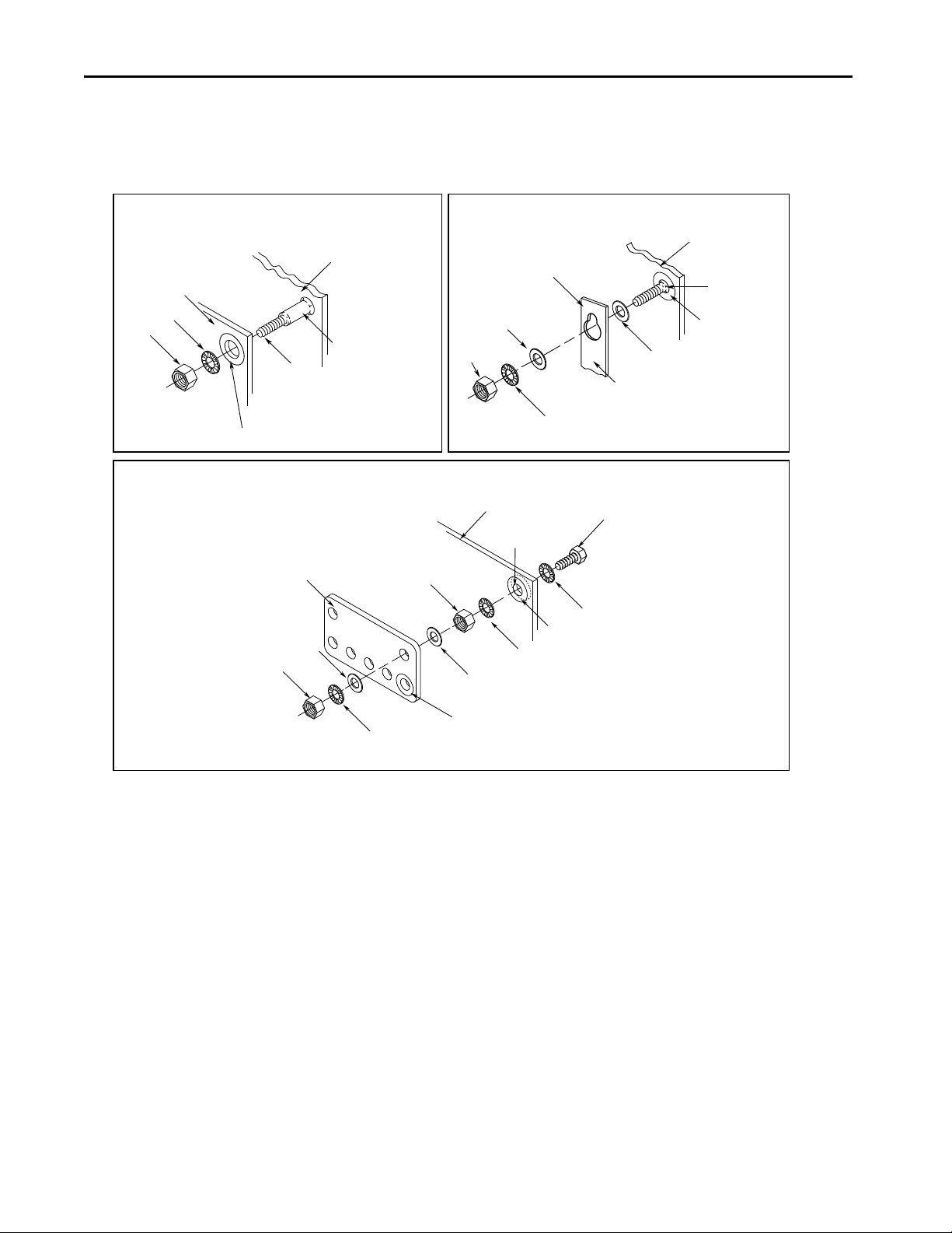
Chapter 2 Plan the Kinetix 5500 Drive System Installation
Stud-mounting the Subpanel
to the Enclosure Back Wall
Stud-mounting a Ground Bus
or Chassis to the Subpanel
Subpanel Weld ed St ud
Scrape Paint
Flat Washer
If the mounting bracket is coated with
a non-conductive material (anodized
or painted), scrape the materia l around
the mounting hole.
Star Washer
Nut
Nut
Flat Washer
Mounting Bracket or
Ground Bus
Use a wire brush to rem ove paint from
threads to maximize ground connection.
Back Wall of
Enclosure
Welded Stud
Subpanel
Star Washer
Use plated panels or scrape paint on
front of panel.
Subpanel
Nut
Nut
Star Washer
Flat Washer
Star Washer
Star Washer
Scrape paint on both sides of
panel and use star washers.
Tapped Hole
Bolt
Flat Washer
Ground Bus or
Mounting Bracket
If the mounting bracket is coated with
a non-conductive material (anodized
or painted), scrape the material around
the mounting hole.
Bolt-mounting a Ground Bus or Chassis to the Back-panel
These illustrations show details of recommended bonding practices for painted
panels, enclosures, and mounting brackets.
Figure 16 - Recommended Bonding Practices for Painted Panels
42 Rockwell Automation Publication 2198-UM001I-EN-P - May 2019
Page 43
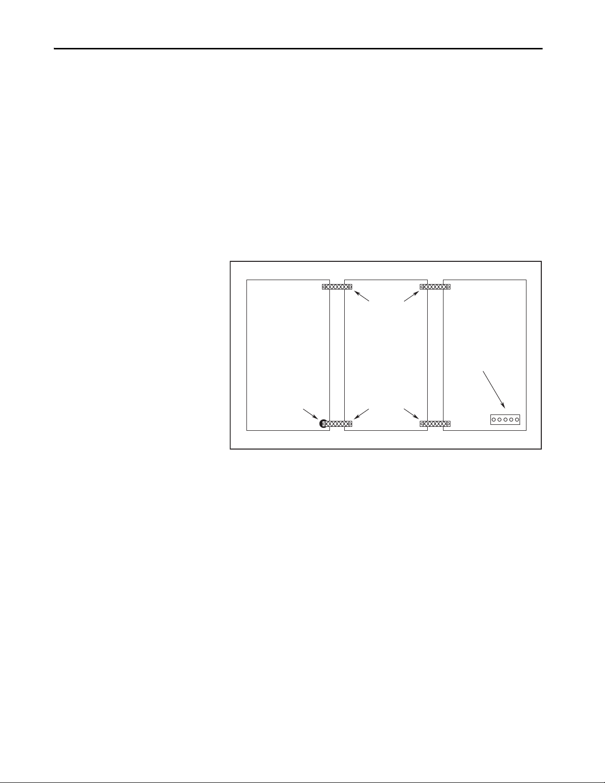
Plan the Kinetix 5500 Drive System Installation Chapter 2
Wire B raid
25.4 mm (1.0 in.) by
6.35 mm (0.25 in.)
Paint removed
from cabinet.
Cabinet ground bus
bonded to the subpanel.
Wire B raid
25.4 mm (1.0 in.) by
6.35 mm (0.25 in.)
Bonding Multiple Subpanels
Bonding multiple subpanels creates a common low impedance exit path for the
high frequency energy inside the cabinet. Subpanels that are not bonded
together do not necessarily share a common low impedance path. This
difference in impedance can affect networks and other devices that span
multiple panels:
• Bond the top and bottom of each subpanel to the cabinet by using
25.4 mm (1.0 in.) by 6.35 mm (0.25 in.) wire braid. As a rule, the wider
and shorter the braid is, the better the bond.
• Scrape the paint from around each fastener to maximize metal-to-metal
contact.
Figure 17 - Multiple Subpanels and Cabinet Recommendations
Rockwell Automation Publication 2198-UM001I-EN-P - May 2019 43
Page 44

Chapter 2 Plan the Kinetix 5500 Drive System Installation
(1)
C
D
D
VD
D
D
C
Dirty Wireway
Clean Wireway
Single Motor Cables
(2)
Circuit
Breakers
24V DC
Power Supply
AC Lin e Filter
(can be required for CE)
Kinetix 5500 Servo Drive System
(1)
(1)
Very Dirty Filter/AC Input Connections
Segregated (not in wireway)
Route single motor cables
in shielded cable.
Route registration and communication
signals in shielded cables.
Safety Cable
(2198-Hxxx-ERS drives only)
Module Status
24V Input
Establishing Noise Zones
Observe these guidelines when routing cables used in the Kinetix 5500 system:
• The clean zone (C) is right of the drive system and includes the digital
inputs wiring and Ethernet cable (gray wireway).
• The dirty zone (D) is above and below the drive system (black wireways)
and includes the circuit breakers, 24V DC power supply, safety, and
motor cables.
• The very dirty zone (VD) is limited to where the AC line (EMC) filter
VAC output jumpers over to the drive (or first drive in multi-axis
systems). Shielded cable is required only if the very dirty cables enter a
wireway.
Figure 18 - Noise Zones
(1) When space to the right of the drive does not permit 150 mm (6.0 in.) segregation, use a grounded steel shield instead. For
examples, refer to the System Design for Control of Electrical Noise Reference Manual, publication GMC-RM001
(2) When 2198-H2DCK converter kit is used, feedback cable routes in the clean wireway.
.
44 Rockwell Automation Publication 2198-UM001I-EN-P - May 2019
Page 45

Plan the Kinetix 5500 Drive System Installation Chapter 2
Cable Categories for Kinetix 5500 Systems
These tables indicate the zoning requirements of cables connecting to the
Kinetix 5500 drive components.
Table 15 - Kinetix 5500 Drive
Zone Method
Wire/Cable Connector
L1, L2, L3 (shielded cable)
L1, L2, L3 (unshielded cable) X – – – –
DC-/DC+ (DC bus) DC Bus-bar only, no wiring connector.
DC+/SH (shunt) RC – X – – –
U, V, W (motor power)
Motor feedback MF X X
Motor brake BC X X
U, V, W (motor power)
Motor feedback
Motor brake BC X – X
24V DC CP – X – – –
Safety enable for safe torque-off (hardwired)
Registration input
Dedicated digital inputs (other than registration inputs) – X – – –
Ethernet
(1) When the 2198-H2DCK converter kit is used, the feedback cable routes in the clean wireway.
(2) STO connector applies to only 2198-Hxxx-ERS (hardwired) servo drives.
(1)
(2)
Kinetix VP
motors/
actuators
MP-Series™
motors/
actuators
IPD
MP
MP
MF – X X
STO – X – – –
IOD
PORT1
PORT2
Very
Dirty
–X–– X
–
–
––X– X
––X– X
Dirty Clean
X
––
X–
Ferrite
Sleeve
–
Shielded
Cable
X
X
Table 16 - Capacitor Module
Zone Method
Wire/Cable Connector
DC-/DC+ (DC bus) DC Bus-bar only, no wiring connector.
24V DC CP – X – – –
Module status MS – X – – –
Rockwell Automation Publication 2198-UM001I-EN-P - May 2019 45
Very
Dirty
Dirty Clean
Ferrite
Sleeve
Shielded
Cable
Page 46

Chapter 2 Plan the Kinetix 5500 Drive System Installation
Noise Reduction Guidelines for Drive Accessories
Refer to this section when mounting an AC (EMC) line filter or external
passive-shunt resistor for guidelines designed to reduce system failures caused
by excessive electrical noise.
AC Line Filters
Observe these guidelines when mounting your AC (EMC) line filter (refer to
the figure on page 44
• Mount the AC line filter on the same panel as the Kinetix 5500 drive
and as close to the drive as possible.
• Good HF bonding to the panel is critical. For painted panels, refer to
the examples on page 42
• Segregate input and output wiring as far as possible.
IMPORTANT CE test certification applies to only the AC line filter used with a single drive
for an example):
.
or the line filter used in multi-axis drive configurations. Sharing a line filter
with more than one multi-axis drive configuration can perform
satisfactorily, but the customer takes legal responsibility.
46 Rockwell Automation Publication 2198-UM001I-EN-P - May 2019
Page 47
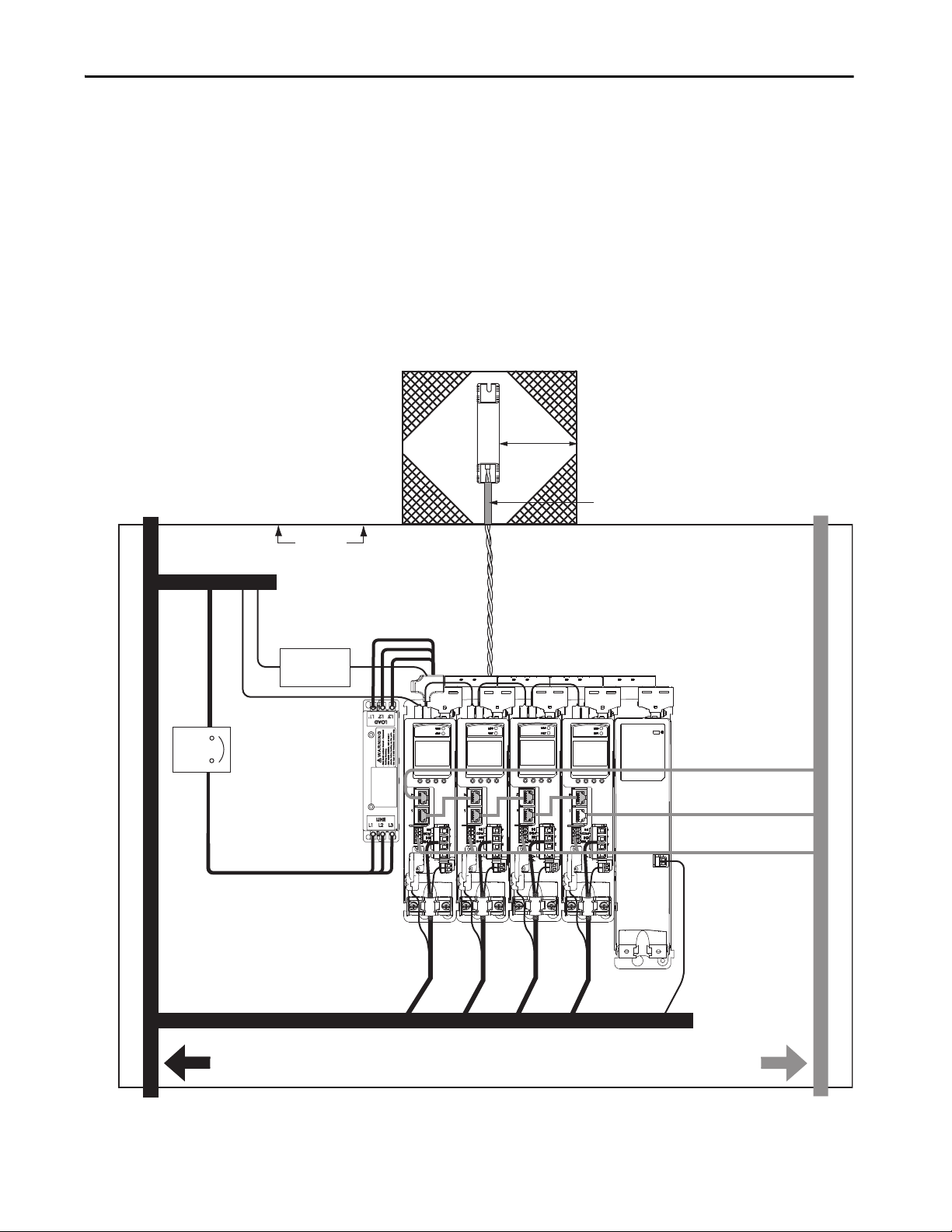
Plan the Kinetix 5500 Drive System Installation Chapter 2
C
D
D
VD
D
D
C
VD
Dirty Wireway
Clean Wireway
Single Motor Cable
Very Dirty Connections Segregated
(not in wireway)
Custom er-sup plied
Metal Enclosure
150 mm (6.0 in.)
clearance (min) on all four
sides of the shunt resistor.
Enclosure
Metal Conduit (where
required by local code)
No sensitive
equipment within
150 mm (6.0 in.).
Shunt Power Wiring Methods:
Twisted pair in conduit (1st choice).
Twisted pair, two twists per foot (min) (2nd choice).
Circuit
Breaker
Route single motor cables
in shielded cable.
Route registration and communication
signals in shielded cables.
Kinetix 5500 Servo Drive System
24V DC
Power Su pply
AC Line Filter
(can be required for CE)
Module Status
Safety Cable
(2198-Hxxx-ERS drives only)
Ethernet and I/O Cables
External Passive Shunt Resistor
Observe these guidelines when mounting your Bulletin 2097 external
passive-shunt resistor outside of the enclosure:
• Mount shunt resistor and wiring in the very dirty zone or in an external
shielded enclosure.
• Mount resistors in a shielded and ventilated enclosure outside of the
cabinet.
• Keep unshielded wiring as short as possible. Keep shunt wiring as flat to
the cabinet as possible.
Figure 19 - External Shunt Resistor Outside the Enclosure
Rockwell Automation Publication 2198-UM001I-EN-P - May 2019 47
Page 48

Chapter 2 Plan the Kinetix 5500 Drive System Installation
C
D
D
VD
D
D
C
VD
Dirty Wireway
Clean Wireway
Single Motor Cable
Very Dirty Connections Segregated
(not in wireway)
Enclosure
No sensitive
equipment within
150 mm (6.0 in.).
Shunt Power Wiring Methods:
Twisted pair in conduit (1st choice).
Twisted pair, two twists per foot (min) (2nd choice).
Circuit
Breaker
Route single motor cables
in shielded cable.
Route registration and communication
signals in shielded cables.
Kinetix 5500 Servo Drive System
24V DC
Power Su pply
AC Line Filter
(can be required for CE)
Module Status
150 mm (6.0 in.)
clearance (min) on all four
sides of the shunt resistor.
Safety Cable
(2198-Hxxx-ERS drives only)
Ethernet and I/O Cables
When mounting your Bulletin 2097 passive-shunt resistor inside the enclosure,
follow these additional guidelines:
• Mount metal-clad modules anywhere in the dirty zone, but as close to
the Kinetix 5500 drive as possible.
• Route shunt power wires with other very dirty wires.
• Keep unshielded wiring as short as possible. Keep shunt wiring as flat to
the cabinet as possible.
• Separate shunt power cables from other sensitive, low voltage signal
cables.
Figure 20 - External Shunt Resistor Inside the Enclosure
48 Rockwell Automation Publication 2198-UM001I-EN-P - May 2019
Page 49

Chapter 3
Mount the Kinetix 5500 Drive System
This chapter provides the system installation procedures for mounting your
Kinetix® 5500 drives to the system panel.
Top ic Pa ge
Determine Mounting Order 50
Drill-hole Patterns 53
Mount Your Kinetix 5500 Drive 60
This procedure assumes you have prepared your panel and understand how to
bond your system. For installation instructions regarding equipment and
accessories not included here, refer to the instructions that came with those
products.
SHOCK HAZARD: To avoid hazard of electrical shock, perform all mounting
and wiring of the Kinetix 5500 drives prior to applying power. Once power is
applied, connector terminals can have voltage present even when not in use.
ATT EN TI ON : Plan the installation of your system so that you can perform all
cutting, drilling, tapping, and welding with the system removed from the
enclosure. Because the system is of the open type construction, be careful to
keep metal debris from falling into it. Metal debris or other foreign matter
can become lodged in the circuitry and result in damage to the components.
Rockwell Automation Publication 2198-UM001I-EN-P - May 2019 49
Page 50

Chapter 3 Mount the Kinetix 5500 Drive System
2198-Hxxx-ERSx Drives
(front view)
Zero-stack Tab and Cutout Engaged
2198-Hxxx-ERSx Drive System
(front view)
Frame 3
Drive
Frame 2
Drives
Frame 1
Drives
2198-CAPMOD-1300 Capacitor Module
(optional component)
Shared-bus Connection System
(required in shared-bus configurations)
Determine Mounting Order
Mount drives in order (left to right) according to power rating (highest to
lowest) starting with the highest power rating. If power rating is unknown,
position drives (highest to lowest) from left to right based on amp rating.
Zero-stack Tab and Cutout
Engaging the zero-stack tab and cutout from drive-to-drive makes efficient use
of panel space for installations with multiple drives.
IMPORTANT Engaging the zero-stack tab and cutout from drive-to-drive is required for
shared-bus multi-axis drive systems. This is done to make sure the drive
connectors are spaced properly to accept the shared-bus connection
system.
Figure 21 - Zero-stack Tab and Cutout Example
For the zero-stack feature to engage properly (when more than one frame size
exists in the drive system) frame 3 drives must mount left of frame 1 or 2 drives,
and frame 2 drives must mount left of frame 1 drives.
Capacitor modules can mount to the right of any frame size, but are always
rightmost in any drive configuration.
IMPORTANT Mount drives in descending order, left to right, according to frame size
with capacitor modules always mounted on the far right.
Figure 22 - Shared-bus Connection System Example
50 Rockwell Automation Publication 2198-UM001I-EN-P - May 2019
Page 51

Mount the Kinetix 5500 Drive System Chapter 3
Input Wiring Connector
(1)
(mains AC input shown)
AC T-connec tors
Bus-bar Connectors
(2)
(AC bus-bars shown)
Input Wiring
(AC input wiring is shown)
Zero-stack Tab
and Cutout Engaged
2198-Hxxx-ERSx Drive System (top view)
Frame 2 drives are shown.
Drive with largest amp rating must be
leftmost drive.
DC Bus Connector Latch
DC Bus T-connector
(3)
Shared-bus Connection System
The shared-bus connection system is used to extend the mains AC input, 24V
control input, and the DC bus power from drive-to-drive in shared-bus multiaxis configurations.
IMPORTANT When the shared-bus connection system is used, the zero-stack tab and
cutout must be engaged between adjacent drives.
The connection system is comprised of three components:
• Input wiring connectors that plug into the leftmost drive and receive
input wiring for mains AC and 24V DC.
• AC bus, DC bus, and 24V DC T-connectors that plug into the drives
downstream from the first where AC, DC, and/or 24V control power is
shared. DC bus T-connectors also plug into the first drive where DC
bus power is shared.
• Bus bars that connect between drives to extend the mains AC bus, DC
bus, and 24V DC control power from drive-to-drive.
Figure 23 - Connection System Example
(1) Due to the higher amp rating of frame 3 drives, input wiring connectors for frame 3 drives (catalog number 2198-H070-ADP-IN)
are slightly larger than connectors for frame 1 and 2 drives (catalog number 2198-H040-ADP-IN).
(2) Due to the extra width of frame 3 drives, bus-bar connectors between frame 3 drives are slightly longer (85 mm) than
connectors between frame 3, frame 2, and frame 1 drives (55 mm).
(3) DC bus T-connectors latch on both sides when inserted into the drive. To remove the DC bus T-connector, at least one latch must
be pried away with a non-conductive probe.
The three components assemble from left to right across the drive system.
1. Attach wiring to input wiring connectors.
2. Insert input wiring connectors and T-connectors into the appropriate
drive connectors.
3. Insert bus-bars to connect between wiring connectors and T-connectors.
Rockwell Automation Publication 2198-UM001I-EN-P - May 2019 51
Page 52

Chapter 3 Mount the Kinetix 5500 Drive System
Single-axis Configurations
The following restrictions exist for standalone (single-axis) configurations:
• Standalone (single-axis) drives can be mounted to the panel individually
or by using the zero-stack tab and cutout (refer to Figure 23 on page 51
• The shared-bus connection system does not apply and must not be used
For a single-axis example configuration, refer to Typical Kinetix 5500
Standalone Installation on page 17.
Multi-axis Configurations
Each multi-axis configuration has restrictions that apply:
• The shared-bus connection system must be used. Do not attach discrete
wires from drive-to-drive.
• The maximum number of drives in Shared AC bus power-sharing
groups cannot exceed 5.
• The maximum number of drives in any other bus power-sharing group
cannot exceed 8.
)
For a multi-axis example configuration, refer to Typical Shared AC/DC Bus
Hybrid Installations on page 21.
52 Rockwell Automation Publication 2198-UM001I-EN-P - May 2019
Page 53
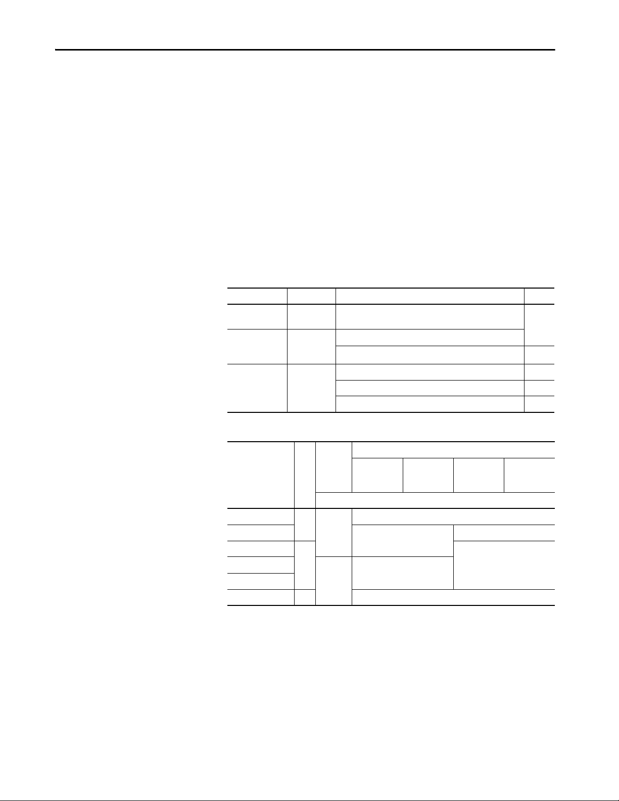
Mount the Kinetix 5500 Drive System Chapter 3
Drill-hole Patterns
Hole patterns for drives mounted in zero-stack or shared-bus configuration are
provided for mounting your drives to the panel. Drives with the highest power
rating are always mounted to the left of any drive with a lower power rating in
shared-bus configurations:
• Frame 1 drives can be followed by only another frame 1 drive.
• Frame 2 drives can be followed by frame 1 drives or another frame 2
drive.
• Frame 3 drives can be followed by frame 1, frame 2, or another frame 3
drive.
• Mount Bulletin 2198 capacitor modules in the rightmost position.
– Capacitor modules have the same hole pattern as frame 2 drives.
– Only Shared DC, Shared AC/DC, and Shared AC/DC, hybrid
configurations are compatible with Bulletin 2198 capacitor modules.
Table 17 - Hole Pattern Overview
Drive Cat. No. Frame Size Frame Size Patterns Page
2198-H003-ERSx
2198-H008-ERSx
2198-H015-ERSx
2198-H025-ERSx
2198-H040-ERSx
2198-H070-ERSx Frame 3
Frame 1 As many as eight frame 1 drives
Frame 2
As many as 8 frame 2 drives
One frame 2 drive followed by as many as seven frame 1 drives 56
As many as 8 frame 3 drives 57
One frame 3 drive followed by as many as seven frame 1 drives 58
One frame 3 drive followed by as many as seven frame 2 drives 59
55
Table 18 - Capacitor Module Support
Three-phase Operation
Drive Cat. No.
Frame Size
2198-H003-ERSx
2198-H008-ERSx
2198-H015-ERSx
2198-H040-ERSx
2198-H070-ERSx 34
(1) Catalog number 2198-H003-ERS and any drive in standalone single-phase operation is not compatible with the Kinetix 5500
capacitor module.
(1)
1
(1)
(1)
0
242198-H025-ERSx
N/A
Standalone Shared DC Shared AC/DC
Standalone
Single Phase
Operation
Number of capacitor modules connected, max
0
1
3
2
Shared AC/DC
Hybrid
Rockwell Automation Publication 2198-UM001I-EN-P - May 2019 53
Page 54

Chapter 3 Mount the Kinetix 5500 Drive System
0
0
243.84
5.00
193.68
0
0
4.51
273.70
0
52.50
0
34.00
8x
ØM4 (#8-32)
Frame 3
Standalone Drive
Frame 1
Standalone Drive
Frame 2
Standalone Drive
Hole spacing is measured in millimeters and not
converted to inches to avoid errors due to rounding.
These hole patterns apply to standalone drives.
Figure 24 - Frame 1, Frame 2, and Frame 3 Standalone Hole Patterns
54 Rockwell Automation Publication 2198-UM001I-EN-P - May 2019
Page 55

Mount the Kinetix 5500 Drive System Chapter 3
Frame Size Dimension Axis 1 Axis 2 Axis 3 Axis 4 Axis 5 Axis 6 Axis 7 Axis 8
1
A 4.51 54.51 104.51 154.51 204.51 254.51 304.51 354.51
B 0 50.0 100.0 150.0 200.0 250.0 300.0 350.02A 5.00 60.0 115.0 170.0 225.0 280.0 335.0 390.0
B 0 55.0 110.0 165.0 220.0 275.0 330.0 385.0
Hole spacing is measured in millimeters and not
converted to i nches to avoid errors due to rounding.
These hole patterns apply when all drives in the system are frame 1 or frame 2.
There is 50 mm (2.0 in.) between mounting holes (A-to-A and B-to-B).
Figure 25 - Frame 1 and Frame 2 Hole Patterns
Axis 8
Axis 7
Axis 6
Axis 5
Axis 4
A
A
A
A
A
B
B
B
B
B
Axis 3
Axis 2
Axis 1
Frame 1
A
A
A
193.68
243.84
Frame 2
50.0
16x
ØM4 (#8-32)
50.0
B
B
B
0
0
Rockwell Automation Publication 2198-UM001I-EN-P - May 2019 55
Page 56

Chapter 3 Mount the Kinetix 5500 Drive System
Hole spacing is measured in millimeters
and not converted to inches to avoid
errors due to rounding.
This hole pattern applies when transitioning from frame 2 drives to frame 1
drives. To mount additional frame 1 drives to the right of Axis 2 in this figure,
refer to the frame 1 hole pattern in Figure 25
Figure 26 - Frame 2 to Frame 1 Hole Pattern
Axis 1
(frame 2)
Axis 2
(frame 1)
.
4x
ØM4 (#8-32)
243.84
243.83
5.00
50.15
0
57.00
0
56 Rockwell Automation Publication 2198-UM001I-EN-P - May 2019
52.50
Page 57

Mount the Kinetix 5500 Drive System Chapter 3
Hole spacing is measured in millimeters and not
converted to inches to avoid errors due to rounding.
This hole pattern applies when all drives in the system are frame 3 drives. There
is 85.20 mm (3.4 in.) between mounting holes, as shown.
Figure 27 - Frame 3 Hole Pattern
648.90
630.40
596.40
563.70
545.20
511.20
478.50
460.0
426.0
Axis 5 Axis 6 Axis 7 Axis 8
Axis 1 Axis 2 Axis 3 Axis 4
374.80
289.60
204.40
119.20
34.00
85.20
85.20
85.20
32x
ØM4 (#8-32)
393.30
340.80
308.10
255.60
222.90
170.40
137.70
85.20
52.50
0
0
273.70
Rockwell Automation Publication 2198-UM001I-EN-P - May 2019 57
Page 58
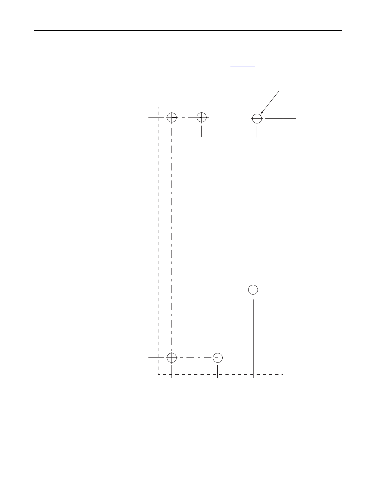
Chapter 3 Mount the Kinetix 5500 Drive System
273.70
0
52.50
0
6x
ØM4 (#8-32)
Axis 1
(frame 3)
Axis 2
(frame 1)
272.23
78.55
92.70
97.20
34.00
Hole spacing is measured in millimeters
and not converted to inches to avoid
errors due to ro unding.
This hole pattern applies when transitioning from frame 3 drives to frame 1
drives. To mount additional frame 1 drives to the right of Axis 2 in this figure,
refer to the frame 1 hole pattern in Figure 25
Figure 28 - Frame 3 to Frame 1 Hole Pattern
.
58 Rockwell Automation Publication 2198-UM001I-EN-P - May 2019
Page 59
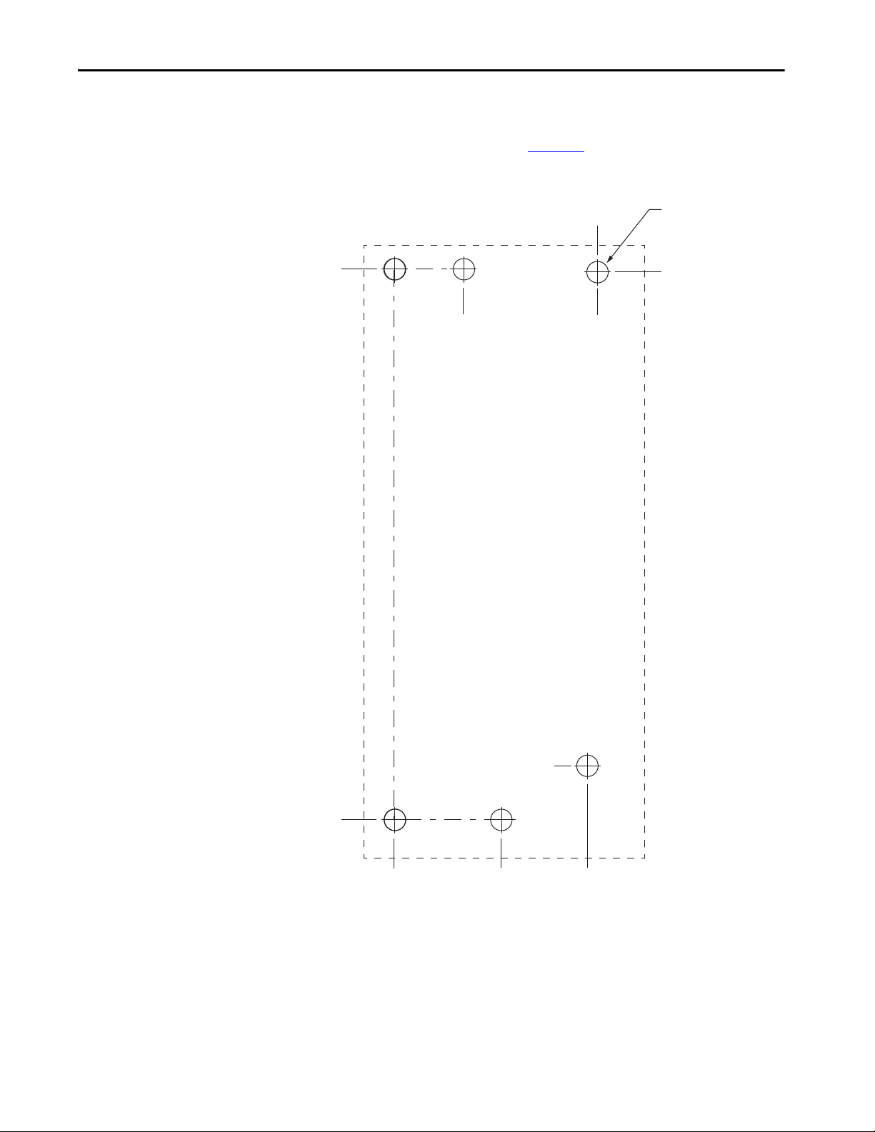
Mount the Kinetix 5500 Drive System Chapter 3
Hole spacing is measured in millimeters
and not conver ted to inches to avoid
errors due to ro unding.
This hole pattern applies when transitioning from frame 3 drives to frame 2
drives. To mount additional frame 2 drives to the right of Axis 2 in this figure,
refer to the frame 2 hole pattern in Figure 25
Figure 29 - Frame 3 to Frame 2 Hole Pattern
Axis 1
(frame 3)
.
Axis 2
(frame 2)
6x
ØM4 (#8-32)
273.70
34.00
272.24
100.00
28.40
0
0
Rockwell Automation Publication 2198-UM001I-EN-P - May 2019 59
52.50
95.00
Page 60
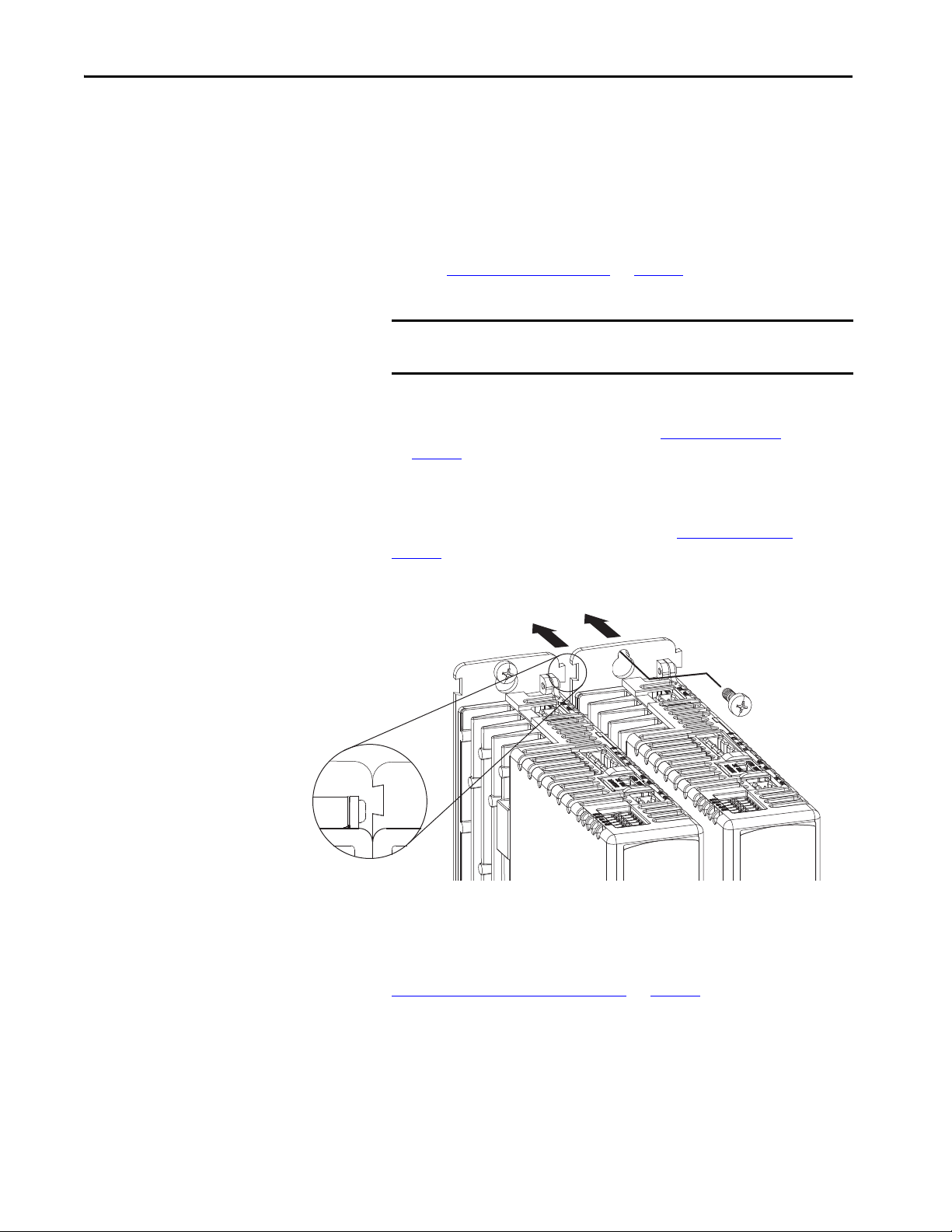
Chapter 3 Mount the Kinetix 5500 Drive System
2
1
Kinetix 5500 Servo Drives
(frame 1 drives shown)
Top Scre ws
(bottom screws not shown)
Zero-s tack Tab
and Cutout Engaged
Mount Your Kinetix 5500 Drive
This procedure assumes you have prepared your panel and understand how to
bond your system. For installation instructions regarding other equipment and
accessories, refer to the instructions that came with those products.
Follow these steps to mount your Kinetix 5500 drives to the panel.
1. Lay out the hole pattern for each Kinetix 5500 drive in the enclosure.
Refer to Establishing Noise Zones
on page 44 for panel layout
recommendations.
IMPORTANT To improve the bond between the Kinetix 5500 drive and subpanel,
construct your subpanel out of zinc plated (paint-free) steel.
2. Drill holes in the panel for mounting your drive system.
Hole patterns, by frame size, are shown in Drill-hole Patterns
on page 53
.
beginning
3. Loosely attach the mounting hardware to the panel.
The recommended mounting hardware is M4 (#8-32) steel bolts.
Observe bonding techniques as described in Bonding Modules
page 41
.
on
4. Attach the leftmost drive to the cabinet panel.
5. Attach additional drives (if any) just to the right of the previous drive by
using the same method, but also making sure the zero-stack tabs and
cutouts are engaged.
Zero-stack mounting is required based on configuration, refer to the
Zero-stack Tab and Cutout Example
on page 50.
6. Tighten all mounting fasteners.
Apply 2.0 N•m (17.7 lb•in) maximum torque to each fastener.
60 Rockwell Automation Publication 2198-UM001I-EN-P - May 2019
Page 61

Chapter 4
Connector Data and Feature Descriptions
This chapter illustrates drive connectors and indicators, including connector
pinouts, and provides descriptions for Kinetix® 5500 drive features.
Top ic Pa ge
Kinetix 5500 Connector Data 62
Understand Control Signal Specifications 67
Feedback Specifications 70
Safe Torque-off Safety Features 72
Rockwell Automation Publication 2198-UM001I-EN-P - May 2019 61
Page 62
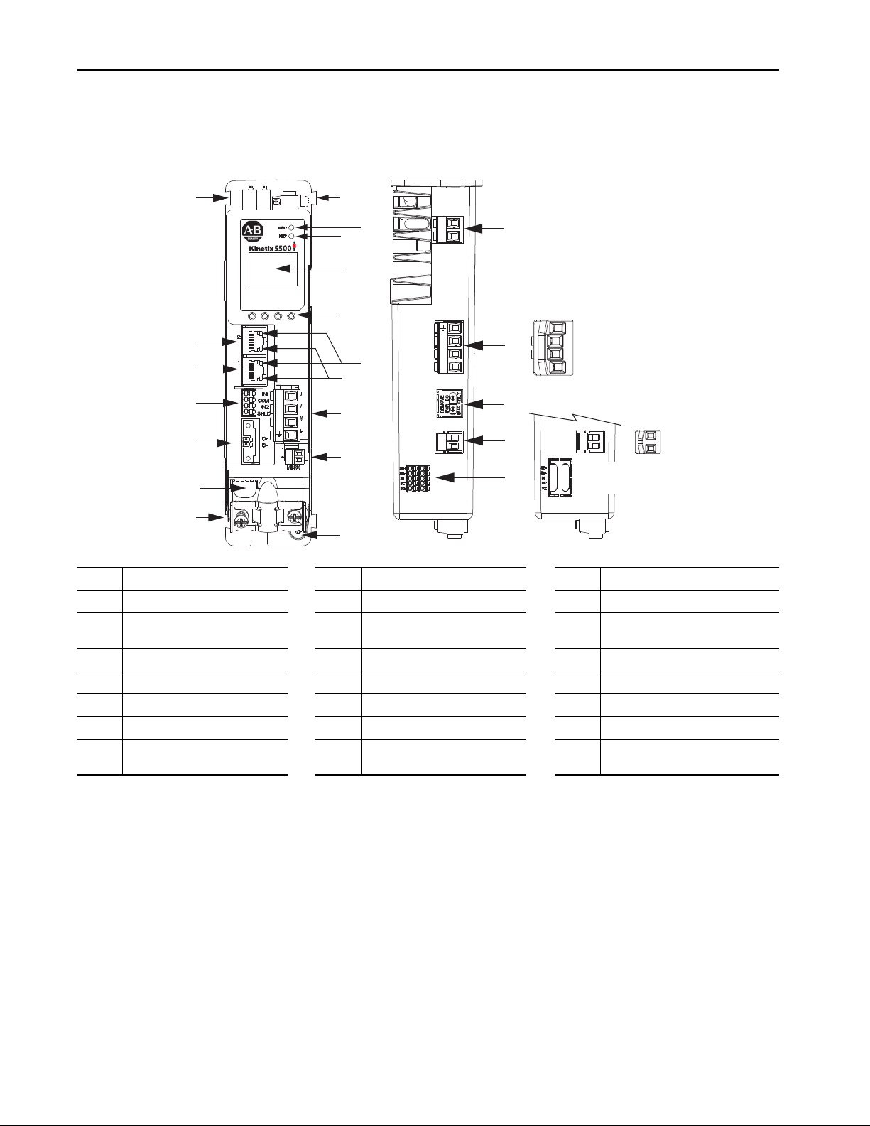
Chapter 4 Connector Data and Feature Descriptions
21
20
19
18
17
1
2
L3
L2
L1
1
2
+
–
1
8
3
4
13
5
6
11
10
9
12
16
7
7
U
V
W
2
1
15
14
2
1
2
Kinetix 5500 Drive, Front View
(2198-H003-ERSx drive is shown)
Kinetix 5500, Top View
(2198-H003-ERS drive is shown)
Kinetix 5500, Top View
(2198-Hxxx-ERS2 drives)
Protect ive
Knock-out
Shared-bus AC Input
Wiring Co nnect or
Shared-bus 24V Input
Wiring Co nnect or
Kinetix 5500 Connector Data
Use these illustrations to identify the connectors and indicators for the
Kinetix 5500 drive modules.
Figure 30 - Kinetix 5500 Drive Features and Indicators
Item Description Item Description Item Description
1 Motor cable shield clamp 8 Module status indicator 15 Motor brake (BC) connector
2
3 Motor feedback (MF) connector 10 LCD display 17 Shunt resistor (RC) connector
4 Digital inputs (IOD) connector 11 Navigation pushbuttons 18 AC mains input power (IPD) connector
5 Ethernet (PORT1) RJ45 connector 12 Link speed status indicators 19 DC bus (DC) connector (under cover)
6 Ethernet (PORT2) RJ45 connector 13 Link/Activity status indicators 20 24V control input power (CP) connector
7 Zero-stack mounting tab/cutout 14 Motor power (MP) connector 21
(1) Protective knock-out covers the 2198-H2DCK Hiperface-to-DSL feedback converter kit mounting hole. Remove knock-out for use with the converter kit.
(2) DC bus connector ships with protective knock-out cover that can be removed for use in shared-bus configurations.
(3) Protective knock-out cover is removed on 2198-Hxxx-ERS (hardwired STO) drives.
62 Rockwell Automation Publication 2198-UM001I-EN-P - May 2019
Converter kit mounting hole
(under cover)
(1)
9 Network status indicator 16 Ground terminal
(2)
Safe torque-off (STO) connector
(3)
(does not apply to 2198-Hxxx-ERS2 drives)
Page 63
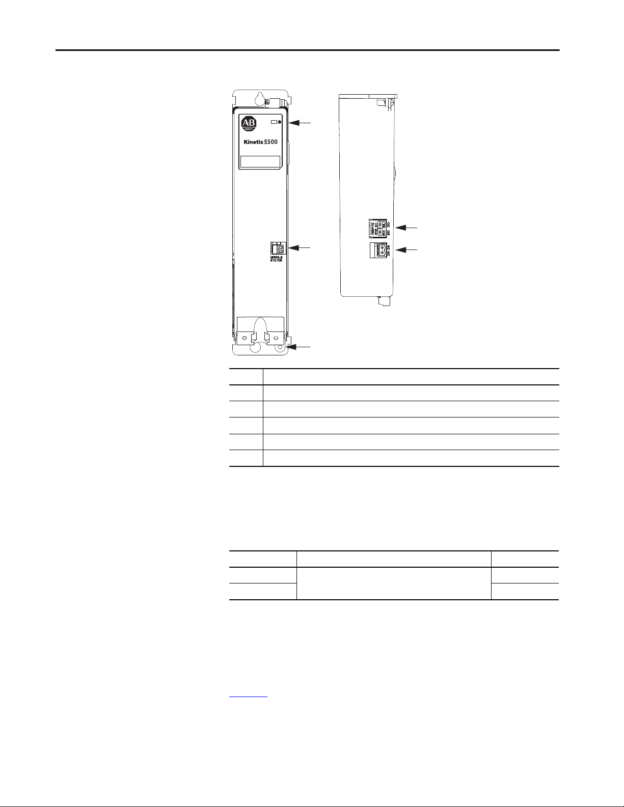
Connector Data and Feature Descriptions Chapter 4
2
1
4
5
2
3
1
Kinetix 5500 Capacitor Module
Top Vie w
Kinetix 5500 Capacitor Module
Front View
Figure 31 - Capacitor Module Features and Indicators
Item Description
1 G round screw (g reen)
2 Module status (MS) connector (relay output)
3 Module status indicator
4 DC bus (DC) connector (under cover)
5 24V control input power (CP) connector
(1) The DC-bus connector ships with a protective knock-out cover that can be removed for use in shared-bus configurations.
(2) The shared-bus connector set for the capacitor module, catalog number 2198-KITCON-CAP1300, is included for connection to
the upstream drive. Replacement kits are also available.
(1) (2)
(2)
Module Status Connector Pinout
MS Pin Description Signal
1
2MS
Module status output
MS
Safe Torque-off Connector Pinout
For the hardwired safe torque-off (STO) connector pinouts, feature
descriptions, and wiring information, refer to Chapter 9 beginning on
page 169
.
Rockwell Automation Publication 2198-UM001I-EN-P - May 2019 63
Page 64

Chapter 4 Connector Data and Feature Descriptions
Input Power Connector Pinouts
Table 19 - Mains Input Power Connector
IPD Pin Description S ignal
Chassis ground
L3
L2 L2
L1 L1
Three-phase input power
L3
Table 20 - 24V Input Power Connector
CP Pin Description Signal
1 24V power supply, customer supplied 24V+
2 24V common 24V-
DC Bus and Shunt Resistor Connector Pinouts
Table 21 - DC Bus Power Connector
DC Pin Description Signal
1
2DC+
DC bus connections
Table 22 - Shunt Resistor Connector
RC Pin Description Signal
1
2SH
1
2DC+
Shunt connections (frames 2 and 3)
Shunt connections (frame 1)
DC-
DC+
SH
64 Rockwell Automation Publication 2198-UM001I-EN-P - May 2019
Page 65

Connector Data and Feature Descriptions Chapter 4
Digital Inputs Connector Pinouts
The Kinetix 5500 drive has two configurable digital inputs and 5 configurable
functions to choose from in the Logix Designer application. Digital input 1
can be configured as a dual-function (home/registration) input.
Table 23 - Digital Inputs Connector
IOD Pin Description Signal
1 24V current-sinking fast input #1. This is a dual-function input. IN1
2 I/O common for customer-supplied 24V supply. COM
3 24V current-sinking fast input #2. IN2
4 I/O cable shield termination point. SHLD
(1) This signal has dual-functionality. You can use IN1 (IOD-1) as Registration 1 or Home input when Home/Registration 1 is
configured.
Table 24 - Configurable Functions
Default Configuration
Digital input1= Home/Registration 1
Digital input2 = Registration 2
(1) Studio 5000 Logix Designer,® version 27 or later, is required to change from the default configuration.
(1)
Description
Unassigned
Home
Registration 1
Registration 2
Positive overtravel
Negative overtravel
Home/Registration 1
(1)
Figure 32 - Pin Orientation for Digital Inputs (IOD) Connector
Pin 1 IN1
COM
IN2
SHLD
Ethernet Communication Connector Pinout
Pin Description Signal
1 Transmit+ TD+
2 Transmit- TD-
3 Receive+ RD+
4 Reserved –
5 Reserved –
6 Receive- RD-
7 Reserved –
8 Reserved –
8
1
Rockwell Automation Publication 2198-UM001I-EN-P - May 2019 65
Page 66

Chapter 4 Connector Data and Feature Descriptions
Pin 1
Pin 2
Motor Power, Brake, and Feedback Connector Pinouts
Table 25 - Motor Power Connector
MP Pin Description Signal Color
U
VVBlack
WWBlue
Three-phase motor power
Chassis ground Green
ATT EN TI ON : To avoid damage to the Kinetix 5500 DC-bus power supply and
inverter, make sure the motor power signals are wired correctly. Refer to MP
Connector Wiring on page 88 for motor power connector wiring examples.
IMPORTANT Drive-to-motor power cables must not exceed 50 m (164 ft), depending on
overall system design.
System performance was tested at this cable length. These limitations also
apply when meeting CE requirements.
UBrown
Table 26 - Motor Brake Connector
BC Pin Description Signal
1
2MBRK-
Motor brake connections
MBRK+
Motor Feedback Connector Pinout
MF Pin Description Signal
1
2D-
SHIELD
Bidirectional data and power for digital encoder interface
Cable shield and grounding plate (internal to 2198-KITCON-DSL connector
kit) termination point
Cable shield and shield clamp (internal to 2198-H2DCK converter kit)
termination point
Figure 33 - Pin Orientation for Motor Feedback (MF) Connector
D+
SHIELD
66 Rockwell Automation Publication 2198-UM001I-EN-P - May 2019
Page 67

Connector Data and Feature Descriptions Chapter 4
Understand Control Signal Specifications
Function Description Default Behavior
Home/Reg1
Registration 1 An inactive-to-active transition (also known as a positive transition) or
Registration 2
Positive overtravel
Negative overtravel
An active state indicates to a homing sequence that the referencing
sensor has been seen. Typically, a transition of this signal is used to
establish a reference position for the machine axis.
active-to-inactive transition (also known as a negative transition) is
used to latch position values for use in registration moves.
The positive/negative limit switch (normally closed contact) inputs for
each axis require 24V DC (nominal).
This section provides a description of the Kinetix 5500 digital inputs, Ethernet
communication, power and relay specifications, encoder feedback
specifications, and safe torque-off features.
Digital Inputs
Two digital inputs are available for the machine interface on the IOD
connector. Digital inputs require a 24V DC @ 15 mA supply. These are
sinking inputs that require a sourcing device. A common and cable shield
connection is provided on the IOD connector for digital inputs.
The Registration 1 input is capable of dual functionality. You can also use this
as the Home input. Configuration for dual functionality is not needed.
IMPORTANT To improve registration input EMC performance, refer to the System Design
for Control of Electrical Noise Reference Manual, publication GMC-RM001
Table 27 - Understand Digital Input Functions
The function is always inactive. You can enable in the Logix
Designer application.
.
Table 28 - Digital Input Specifications
Attribute Value
Type Active high, single-ended, current sinking (EN 61131-2 Type 1)
Dedicated functions Registration 1, Home, Registration 2, Positive overtravel, Negative overtravel
Input current (with 24V applied) 12 mA, typical
On-state input voltage 15…30V @ 15 mA, max
Off-state input voltage -1.0…5.0V
Pulse reject filtering (registration functions) 12.0 μs
Pulse reject filtering (home input function) debounce filter 20 ms, nom
Propagation delay (registration functions) 0 (delay compensated)
Registration accuracy ±3 μs
Registration repeatability 700 ns
Windowed registration invalid-to-valid event delay 125 μs, min
Rockwell Automation Publication 2198-UM001I-EN-P - May 2019 67
Page 68

Chapter 4 Connector Data and Feature Descriptions
Kinetix 5500 Drive
24V DC
Figure 34 - Digital Input Circuitry
INx
COM
IOD-1 or IOD-3
IOD-2
Ethernet Communication Specifications
The PORT1 and PORT2 (RJ45) Ethernet connectors are provided for
communication with the Logix 5000™ controller.
Attribute Value
Communication
Cyclic update period 1.0 ms, min
Embedded switch features
Auto MDI/MDIX crossover detection/
correction
Port-to-port time synchronization
variation
Cabling CAT5e shielded, 100 m (328 ft) max
The drive auto-negotiates speed and duplex modes. These modes can
be forced through the Logix Designer application. 100BASE-TX, full
duplex is recommended for maximum performance.
Three-port, cut-through, time correction on IEEE-1588 packets, limited
filtering, quality of service with four priority levels
Yes
100 ns, max
INPUT
Motor Brake Circuit
The brake option is a spring-set holding brake that releases when voltage is
applied to the brake coil in the motor. The customer-supplied 24V power
supply drives the brake output through a solid-state relay. The solid-state brake
driver circuit provides the following:
• Brake current-overload protection
• Brake over-voltage protection
Two connections (BC-1 and BC-2) are required for the motor brake output.
Connections are rated for 2.0 A @ +24V (refer to Figure 35
68 Rockwell Automation Publication 2198-UM001I-EN-P - May 2019
).
Page 69

Figure 35 - Motor Brake Circuit
Kinetix 5500
Servo Drive
Control
Board
Inductive
Energy
Clamp
Connector Data and Feature Descriptions Chapter 4
ISP772
24V COM
24V PWR
MBRK+ (BC-1)
MBRK– (BC-2)
INT PWR
IMPORTANT Motor parking-brake switching frequency must not exceed
10 cycles/min.
Control of the solid-state relay to release the motor brake is configurable in the
Logix Designer application (refer to Configure SPM Motor Closed-loop
Control Axis Properties beginning on page 138). An active signal releases the
motor brake. Turn-on and turn-off delays are specified by the
MechanicalBrakeEngageDelay and MechanicalBrakeReleaseDelay settings.
IMPORTANT Holding brakes that are available on Allen-Bradley® rotary motors are
designed to hold a motor shaft at 0 rpm for up to the rated brakeholding torque, not to stop the rotation of the motor shaft, or be used as
a safety device.
You must command the servo drive to 0 rpm and engage the brake only
after verifying that the motor shaft is at 0 rpm.
These steps provide one method you can use to control a brake.
1. Wire the mechanical brake according to the appropriate interconnect
diagram in Appendix A beginning on page 193
.
2. Enter the MechanicalBrakeEngageDelay and Mechanical
BrakeReleaseDelay times in the Logix Designer application.
Refer to Axis Properties>Parameter List. The delay times must be from
the appropriate motor family brake specifications table in the Kinetix
Rotary Motion Specifications Technical Data, publication
KNX-TD001
.
3. Use the drive stop-action default setting (Current Decel & Disable).
Refer to Axis Properties>Actions>Stop Action in the Logix Designer
application.
4. Use the motion instruction Motion Axis Stop (MAS) to decelerate the
servo motor to 0 rpm.
5. Use the motion instruction Motion Servo Off (MSF) to engage the
brake and disable drive.
Rockwell Automation Publication 2198-UM001I-EN-P - May 2019 69
Page 70

Chapter 4 Connector Data and Feature Descriptions
Control Power
The Kinetix 5500 drive requires 24V DC input power for control circuitry.
IMPORTANT SELV and PELV rated power supplies must be used to energize external
safety devices connected to the Kinetix 5500 safety inputs.
The National Electrical Code and local electrical codes take precedence over
the values and methods provided. Implementation of these codes is the
responsibility of the machine builder.
Table 29 - Control Power Input Power Specifications
Attribute Frame 1 Frame 2 Frame 3
Input voltage 21.6…26.4V DC
Control power AC input current
Nom @ 24V DC
Inrush, max
(1) Plus BC connector (MBRK+) current.
(1)
400 mA
2.0 A
800 mA
3.0 A
1.3 A
3.0 A
Feedback Specifications
The Kinetix 5500 drive accepts motor feedback signals from Stegmann
Hiperface digital-servo-link (DSL) encoders on the motor feedback (MF)
connector.
TIP Auto-configuration in the Logix Designer application of intelligent absolute,
high-resolution encoders is possible with only Allen-Bradley motors.
The Kinetix 5500 drives support Kinetix VP motors with Stegmann Hiperface
digital-servo-link (DSL) encoders by using the 2-pin (MF) feedback
connector. You can also use the MF connector for feedback-only applications.
Other Allen-Bradley motors and actuators with Stegmann Hiperface singleturn or multi-turn high-resolution absolute encoders are also accepted, but
only when using drive firmware revision 2.002 or later, and the 2198-H2DCK
Hiperface-to-DSL (series B or later) feedback converter kit.
Table 30 - Stegmann Hiperface DSL Specifications
Attribute Value
Protocol Hiper face DSL
Memory support Programmed with Allen-Bradley motor data
Hiperface data communication 9.375 Mbits/s
70 Rockwell Automation Publication 2198-UM001I-EN-P - May 2019
Page 71

Connector Data and Feature Descriptions Chapter 4
+2048-2048 +1024-1024
+64
-64
+256-256
+512
-512
0
-128
+128
Position at Power D own
4096 Turns
2048 Turns
512 Turns
Absolute Position Feature
The absolute position feature of the drive tracks the position of the motor,
within the multi-turn retention limits, while the drive is powered off. The
absolute position feature is available with only multi-turn encoders.
Table 31 - Absolute Position Retention Limits
Encoder Type
Stegmann Hiperface (DSL)
Stegmann Hiperface
Stegmann Hiperface (magnetic scale) -xDx –LDAT-Sxxxxxx-xDx – 960 (37.8)
Cat. No.
Designator
-P
-W
-Q
-M
-V MPL-A/Bxxxxx-V
Motor Cat. No. Actuator Cat. No.
VPL-A/Bxxxxx-P
VPF-A/Bxxxxx-P
VPS-Bxxxxx-P
VPL-A/Bxxxxx-W,
VPF-A/Bxxxxx-W
VPH-A/Bxxxxx-W
VPL-A/Bxxxxx-Q
VPF-A/Bxxxxx-Q
VPH-A/Bxxxxx-Q
MPL-A/Bxxxxx-M
MPM-A/Bxxxxx-M
MPF-A/Bxxxxx-M
MPS-A/Bxxxxx-M
Turns (rotary) mm (linear)
VPAR-A/Bxxxxx-P 4096 (±2048) –
VPAR-Bxxxxx-W 4096 (±2048) –
VPAR-Bxxxxx-Q 512 (±256) –
MPAR-A/B3xxxx-M
MPAI-A/BxxxxxM
MPAS-A/Bxxxx1-V05, MPAS-A/Bxxxx2-V20
MPAR-A/B1xxxx-V, MPAR-A/B2xxxx-V
MPAI-A/BxxxxxV
2048 (±1024) –
4096 (±2048) –
Retention Limits
Figure 36 - Absolute Position Limits (measured in turns)
Rockwell Automation Publication 2198-UM001I-EN-P - May 2019 71
Page 72

Chapter 4 Connector Data and Feature Descriptions
Safe Torque-off Safety Features
Kinetix 5500 servo drives have safe torque-off (STO) capability and can safely
turn off the inverter power transistors in response to a monitored digital input,
according to Category 0 Stop behavior.
Servo Drives with Hardwired Safety
2198-Hxxx-ERS (hardwired) servo drives support parallel input terminals for
cascading to adjacent drives over duplex wiring. For applications that do not
require the STO safety function you must install jumper wires to bypass the
safe torque-off feature.
Refer to Chapter 9 on page 169
and wiring information.
for the STO connector pinout, installation,
Servo Drives with Integrated Safety
For 2198-Hxxx-ERS2 (integrated safety) servo drives, the GuardLogix® 5570
or Compact GuardLogix 5570 safety controller issues the STO command via
the EtherNet/IP™ network and the 2198-Hxxx-ERS2 servo drives execute the
command.
Refer to Chapter 10 on page 177
configuring motion and safety connections, motion direct commands, and the
STO bypass feature.
for integrated safety drive specifications,
72 Rockwell Automation Publication 2198-UM001I-EN-P - May 2019
Page 73

Chapter 5
Connect the Kinetix 5500 Drive System
This chapter provides procedures for wiring your Kinetix® 5500 system
components and making cable connections.
Top ic Pa ge
Basic Wiring Requirements 74
Determine the Input Power Configuration 75
Ground Screw Settings 78
Remove the Ground Screws in Select Power Configurations 79
Ground the Drive System 80
Wiring Requirements 82
Wiring Guidelines 83
Wire the Power Connectors 84
Wire the Digital Input Connectors 86
Wire Kinetix VP Motors and Actuators 87
Wire Other Allen-Bradley Motors and Actuators 92
Capacitor Module Connections 104
External Passive-shunt Resistor Connections 105
Ethernet Cable Connections 106
Rockwell Automation Publication 2198-UM001I-EN-P - May 2019 73
Page 74
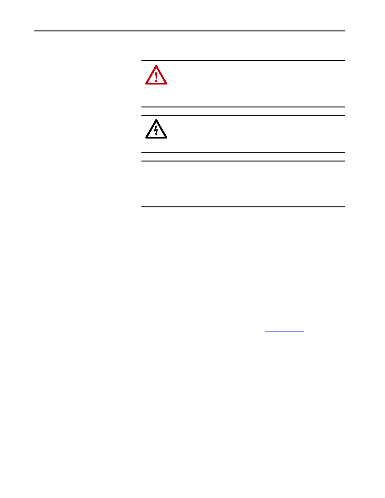
Chapter 5 Connect the Kinetix 5500 Drive System
Basic Wiring Requirements
This section contains basic wiring information for the Kinetix 5500 drives.
ATT EN TI ON : Plan the installation of your system so that you can perform all
cutting, drilling, tapping, and welding with the system removed from the
enclosure. Because the system is of the open type construction, be careful to
keep metal debris from falling into it. Metal debris or other foreign matter
can become lodged in the circuitry and result in damage to components.
SHOCK HAZARD: To avoid hazard of electrical shock, perform all mounting
and wiring of the Bulletin 2198 drive modules prior to applying power. Once
power is applied, connector terminals can have voltage present even when
not in use.
IMPORTANT This section contains common PWM servo system wiring configurations,
size, and practices that can be used in a majority of applications. National
Electrical Code, local electrical codes, special operating temperatures, duty
cycles, or system configurations take precedence over the values and
methods provided.
Routing the Power and Signal Cables
Be aware that when you route power and signal wiring on a machine or system,
radiated noise from nearby relays, transformers, and other electronic devices
can be induced into I/O communication, or other sensitive low voltage signals.
This can cause system faults and communication anomalies.
The Bulletin 2090 single motor cable contains the power, brake, and feedback
wires, but is properly shielded to protect the noise-sensitive feedback signals.
Refer to Electrical Noise Reduction
and low voltage cables in wireways. Refer to the System Design for Control of
Electrical Noise Reference Manual, publication GMC-RM001
information.
on page 41 for examples of routing high
, for more
74 Rockwell Automation Publication 2198-UM001I-EN-P - May 2019
Page 75
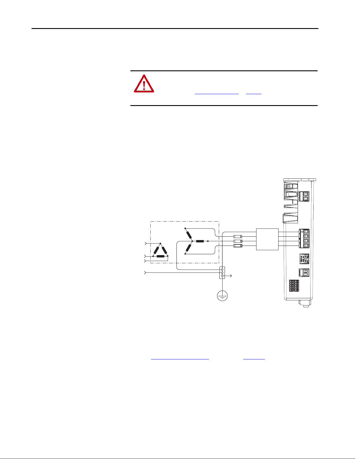
Connect the Kinetix 5500 Drive System Chapter 5
Transformer
Three- phase
Input VAC
Phase Ground
Transformer (WYE) Secondary
Bonded Cabinet Ground
Ground Grid or
Power Distribution Ground
Three-phas e
(1)
AC Line Fi lter
(can be req uired
for CE)
Kinetix 5500 Servo Drive
(top view)
Circuit
Protection
Connect to
Ground Stud
Determine the Input Power Configuration
Before wiring input power to your Kinetix 5500 system, you must determine
the type of input power within your facility. The drive is designed to operate in
both grounded and ungrounded environments.
ATT EN TI ON : Ungrounded, corner-grounded, and impedance-grounded
input power configurations are permitted, but you must remove the ground
screws. Refer to Ground Screw Settings
on page 78 for a ground screw
summary.
Grounded Power Configurations
The grounded (WYE) power configuration lets you ground your three-phase
power at a neutral point. This type of grounded power configuration is
preferred.
Figure 37 - Grounded Power Configuration (WYE Secondary)
2
1
(1) When using 2198-DBxx-F line filter, the AC ground jumper is installed and the DC ground jumper is installed. When using
2198-DBRxx-F line filter, the AC ground jumper is installed and the DC ground jumper is installed.
The Kinetix 5500 drive has factory-installed ground screws for grounded (wye)
power distribution.
Refer to Power Wiring Examples
interconnect diagrams.
L3
L2
L1
beginning on page 194 for input power
L3
L2
L1
2
1
Rockwell Automation Publication 2198-UM001I-EN-P - May 2019 75
Page 76

Chapter 5 Connect the Kinetix 5500 Drive System
Transformer
Three-phase
Input VAC
Phase Ground
Transformer (WYE) Secondary
Bonded Cabinet Ground
Ground Grid or
Power Distribution Ground
Kinetix 5500 Servo Drive
(top view)
Circuit
Protection
Connect to
Ground Stud
AC Screw
(1)
DC Screw
Transformer (Delta) Secondary
Bonded Cabinet Ground
Transformer
Ground Grid or
Power Distribution Ground
Kinetix 5500 Servo Drive
(top view)
Circuit
Protection
Connect to
Ground Stud
AC Screw
(1)
DC Screw
Figure 38 - Impedance-grounded Power Configuration (WYE Secondary)
2
1
L3
L2
L3
L2
L1
L1
2
1
(1) The AC ground jumper is removed and the DC ground jumper is removed. See Figure 42 on page 79 for access to ground screws.
Figure 39 - Corner-grounded Power Configuration (Delta Secondary)
2
1
L3
L3
L2
L1
L2
L1
76 Rockwell Automation Publication 2198-UM001I-EN-P - May 2019
(1) The AC ground jumper is removed and the DC ground jumper is removed. See Figure 42 on page 79 for access to ground screws.
Refer to Power Wiring Examples beginning on page 194 for input power
interconnect diagrams.
2
1
Page 77
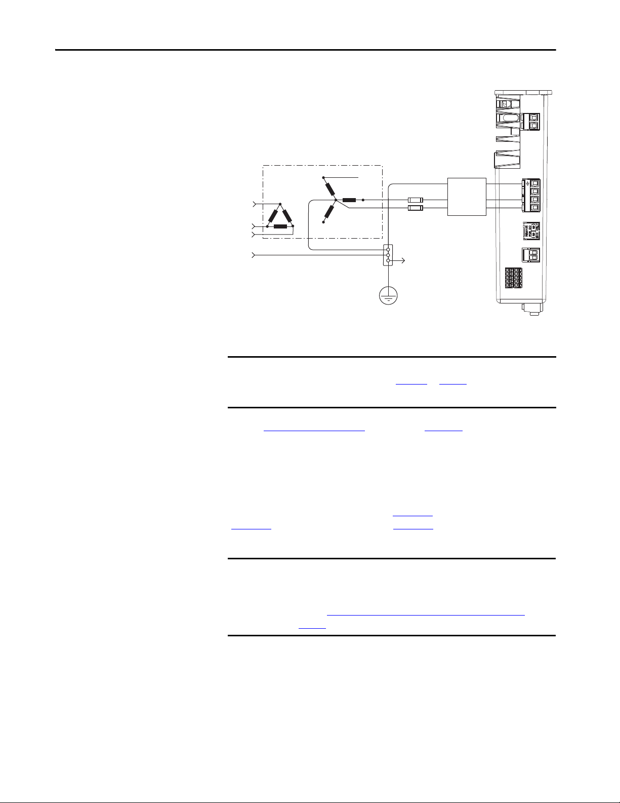
Connect the Kinetix 5500 Drive System Chapter 5
Transformer
Three-phase
Input VAC
Phase Ground
Transformer (WYE) Secondary
Bonded Cabinet Ground
Ground Grid or
Power Distribution Ground
Kinetix 5500 Servo Drive
(top view)
Circuit
Protection
Connect to
Ground Stud
Three- phase
(1)
AC Lin e Filter
(can be require d
for CE)
Figure 40 - Grounded Power Configuration (single-phase input)
2
1
L3
L2
L1
(1) When using 2198-DBxx-F line filter, the AC ground jumper is installed and the DC ground jumper is installed. When using
2198-DBRxx-F line filter, the AC ground jumper is installed and the DC ground jumper is installed.
L3
L2
L1
2
1
IMPORTANT To reduce leakage current in single-phase AC input operation, remove the
Refer to Power Wiring Examples beginning on page 194 for input power
interconnect diagrams.
Ungrounded Power Configurations
The ungrounded power configuration (Figure 41), corner-grounded
(Figure 39
not provide a neutral ground point.
IMPORTANT If you determine that you have ungrounded, corner-grounded, or
AC ground screw (refer to Figure 42
on page 79).
Install the AC ground screw only if higher EMC performance is required.
), and impedance-grounded (Figure 38) power configurations do
impedance-grounded power distribution in your facility, you must remove
the ground screws in each of your drives that receive input power.
Refer to Remove the Ground Screws in Select Power Configurations
page 79
for more information.
on
Rockwell Automation Publication 2198-UM001I-EN-P - May 2019 77
Page 78
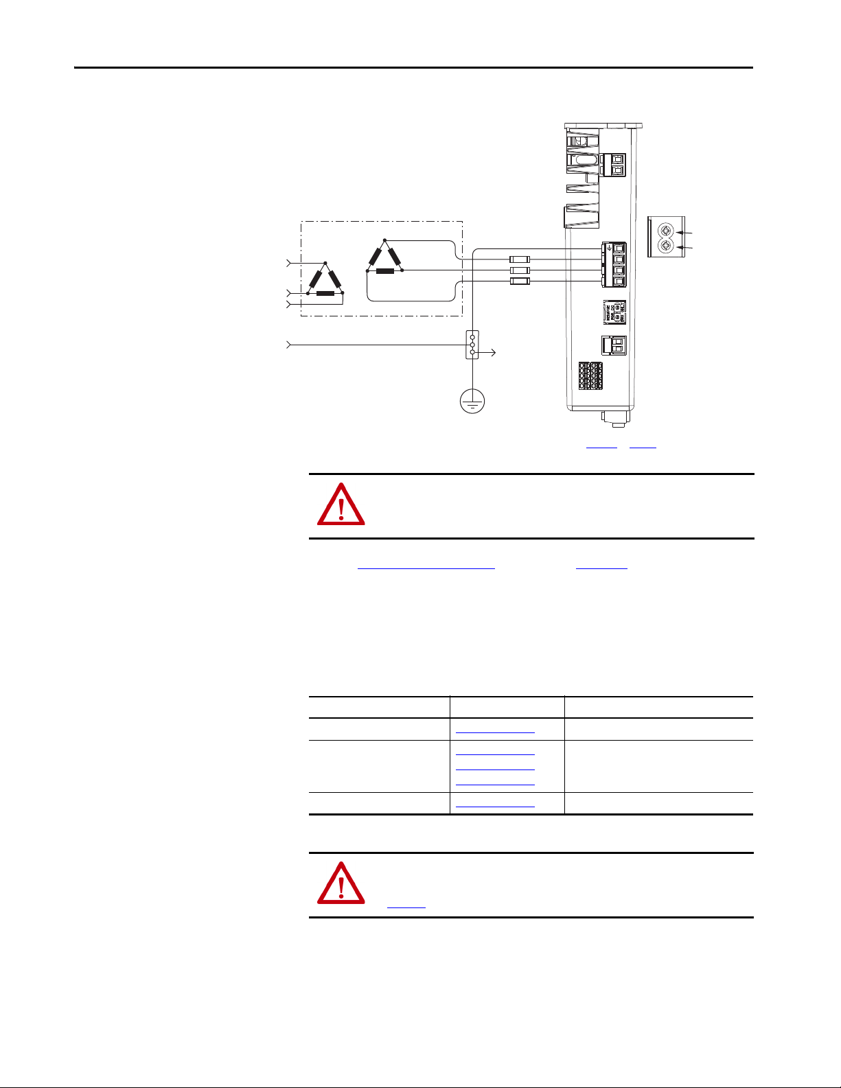
Chapter 5 Connect the Kinetix 5500 Drive System
L3
L2
L1
1
2
L3
L2
L1
1
2
Transformer
Three- phase
Input VAC
Chassis Ground
Bonded Cabinet Ground
Ground Grid or
Power Distribution Ground
Connect to
Ground Stud
Kinetix 5500 Servo Drive
(top view)
Circuit
Protection
Transformer (Delta) Secondary
AC Screw
(1)
DC Screw
Figure 41 - Ungrounded Power Configuration
(1) The AC ground jumper is removed and the DC ground jumper is removed. See Figure 42 on page 79 for access to ground screws.
Ground Screw Settings
ATT EN TI ON : Ungrounded systems do not reference each phase potential to
a power distribution ground. This can result in an unknown potential to earth
ground.
Refer to Power Wiring Examples beginning on page 194 for input power
interconnect diagrams.
Determine the ground screw setting for your Kinetix 5500 servo drives.
Table 32 - Ground Screw Settings
Ground Configuration Example Diagram Ground Screw Setting
Grounded (wye) Figure 37 on page 75
• AC fed ungrounded
• Corner grounded
• Impedance grounded
Single-phase input power Figure 40 on page 77 AC screw removed
(1) Removing the AC ground screw to minimize leakage current in single-phase operation can affect EMC performance.
Figure 41 on page 78
Figure 39 on page 76
Figure 38 on page 76
Both screws installed (default setting)
Both screws removed
(1)
ATT EN TI ON : To help prevent damage to the servo drive, you must set the
ground screws according to the example diagrams that are summarized in
Tab le 3 2
.
78 Rockwell Automation Publication 2198-UM001I-EN-P - May 2019
Page 79
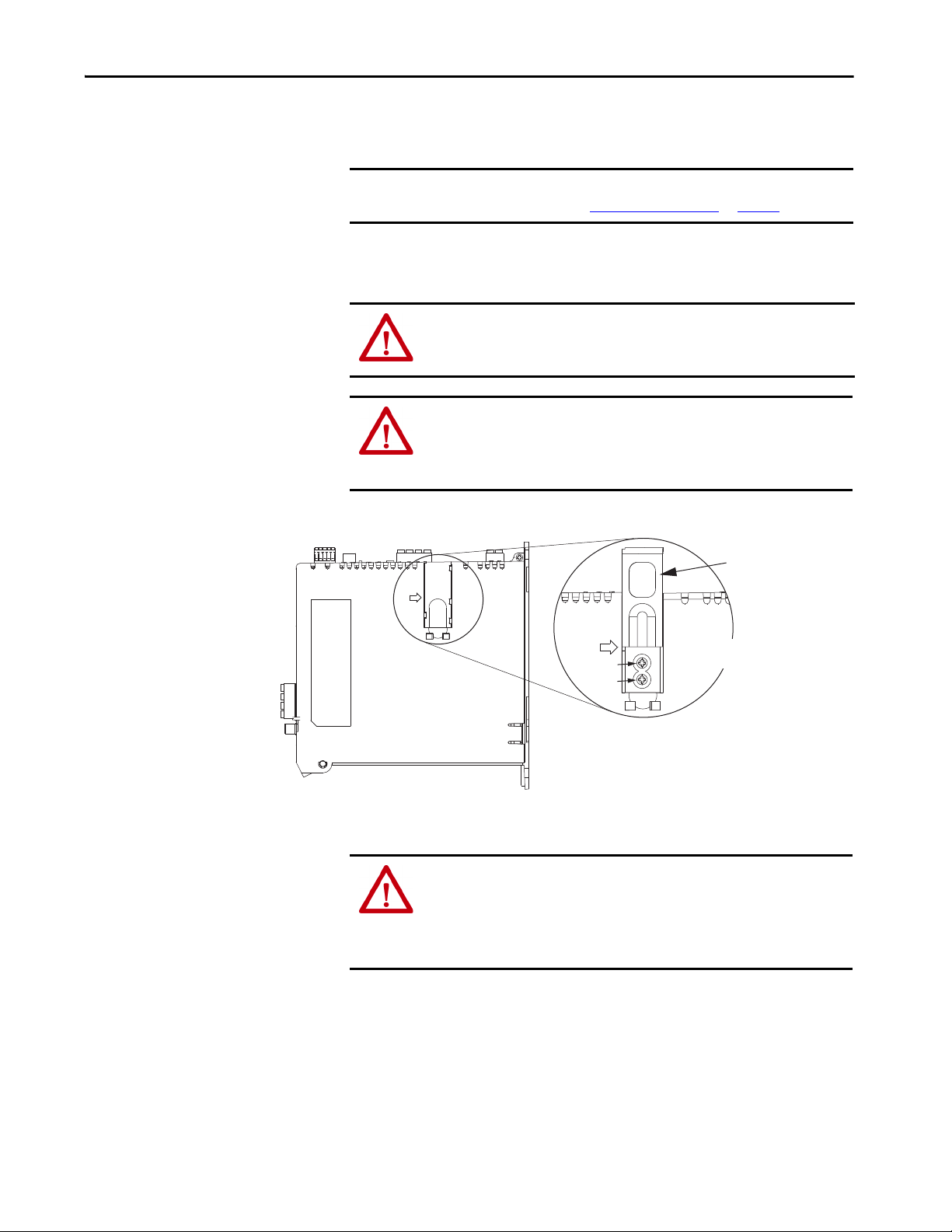
Connect the Kinetix 5500 Drive System Chapter 5
Ground screws installed for grounded power configuration
(screws installed is default setting).
• Remove both screws for ungrounded, corner-grounded, and
impedance-grounded power for three-phase operation
• Remove only the AC screw for single-phase operation
Ground Screws
Access Door
Kinetix 5500 Drive
(side view)
Lift door to meet
arrow at left.
AC Screw
DC Screw
Remove the Ground Screws in Select Power Configurations
Removing the ground screws involves gaining access, opening the sliding door,
and removing the screws.
IMPORTANT If you have grounded-wye power distribution, you do not need to remove
the ground screws. Go to Ground the Drive System
on page 80.
Removing the ground screws in multi-axis configurations is best done when
each drive is removed from the panel and placed on its side on a solid surface.
ATT EN TI ON : Because the unit no longer maintains line-to-neutral voltage
protection, the risk of equipment damage exists when you remove the
ground screws.
ATT EN TI ON : To avoid personal injury, the ground screws access door must
be kept closed when power is applied. If power was present and then
removed, wait at least 5 minutes for the DC-bus voltage to dissipate and
verify that no DC-bus voltage exists before accessing the ground screws.
Figure 42 - Remove the Ground Screws
ATT EN TI ON : Risk of equipment damage exists. The drive ground
configuration must be accurately determined. Leave the ground screws
installed for grounded power configurations (default). Remove the screws
for ungrounded, corner-grounded, and impedance-grounded power
configurations.
Rockwell Automation Publication 2198-UM001I-EN-P - May 2019 79
Page 80

Chapter 5 Connect the Kinetix 5500 Drive System
Braided Ground Straps
12 mm (0.5 in.) by 0.8 mm (0.03 in.)
Keep straps as short as possible.
4
3
2
1
Kinetix 5500
Servo Drive
(standalone)
Kinetix 5500
Servo Drives
(shared-bus)
Ground the Drive System
All equipment and components of a machine or process system must have a
common earth ground point connected to chassis. A grounded system provides
a ground path for protection against electrical shock. Grounding your drives
and panels minimize the shock hazard to personnel and damage to equipment
caused by short circuits, transient overvoltages, and accidental connection of
energized conductors to the equipment chassis.
ATT EN TI ON : The National Electrical Code contains grounding requirements,
conventions, and definitions. Follow all applicable local codes and
regulations to safely ground your system.
For CE grounding requirements, refer to Agency Compliance
on page 30.
Ground the System Subpanel
Ground Kinetix 5500 drives and 2198-CAPMOD-1300 capacitor modules to
a bonded cabinet ground bus with a braided ground strap. Keep the braided
ground strap as short as possible for optimum bonding.
Figure 43 - Connecting the Ground Terminal
Item Description
1 Ground screw (green) 2.0 N• m (17.7 lb•in), max
2 Braided ground strap (customer supplied)
3 Ground grid or power distribution ground
4 Bonded cabinet ground bus (customer supplied)
Refer to the System Design for Control of Electrical Noise Reference Manual,
publication GMC-RM001
80 Rockwell Automation Publication 2198-UM001I-EN-P - May 2019
, for more information.
Page 81

Connect the Kinetix 5500 Drive System Chapter 5
Follow NEC and applicable
local codes.
Bonded Ground Bus
Ground Grid or Power
Distribution Ground
Ground Multiple Subpanels
In this figure, the chassis ground is extended to multiple subpanels.
Figure 44 - Subpanels Connected to a Single Ground Point
High-frequency (HF) bonding is not illustrated. For HF bonding information,
refer to Bonding Multiple Subpanels
on page 43.
Rockwell Automation Publication 2198-UM001I-EN-P - May 2019 81
Page 82

Chapter 5 Connect the Kinetix 5500 Drive System
L3
L2
L1
L3
L2
L1
U
V
W
U
V
W
Wiring Requirements
Kinetix 5500 Drive
Cat. No.
2198-H003-ERSx
2198-H008-ERSx
2198-H015-ERSx
2198-H025-ERSx
2198-H040-ERSx
2198-H070-ERSx
2198-H003-ERSx
2198-H008-ERSx
2198-H015-ERSx
2198-H025-ERSx
2198-H040-ERSx
2198-H070-ERSx
2198-xxxx-ERSx
(1) The wire size, strip length, and torque specifications shown here apply to the single-axis connector that ships with the drive. For the shared-bus connector specifications, refer to
Tab le 3 5
(2) These signals and the safe torque-off (STO) connector apply to only the 2198-Hxxx-ERS drives.
(3) This signal has dual-functionality. You can use IN1 (IOD-1) as registration or Home input.
(4) Building your own cables or using third-party cables is not an option. Use single motor cable catalog number 2090-CSxM1DF-xxAAxx. Refer to the Kinetix Motion Accessories
(5) Motor brake wires are part of the 2090-CSBM1DF/DG-xxAAxx motor cable.
(6) DC bus connections are always made from drive-to-drive over the bus-bar connection system. These terminals do not receive discrete wires.
(7) This connector uses spring tension to hold wires in place.
on page 84 (CP connector) and Tab le 3 7 on page 86 (IPD connector).
Specifications Technical Data, publication KNX-TD004
Wires must be copper with 75 °C (167 °F) minimum rating. Phasing of main
AC power is arbitrary and earth ground connection is required for safe and
proper operation.
Refer to Power Wiring Examples
IMPORTANT The National Electrical Code and local electrical codes take precedence
Table 33 - Power and I/O Wiring Requirements
Description
Mains input power
(single-axis IPD connector)
Motor power
PELV/SELV 24V power
(single-axis CP connector)
Brake power
DC Bus power
Shunt resistor
(frame 2 and 3)
Shunt resistor
(frame 1)
(2)
Safety
Digital inputs
(1)
(1)
, for cable specifications.
over the values and methods provided.
Connects to Terminals
Pin Signal
CP-1
CP-2
BC-1
BC-2
DC-1
DC-2
RC-1
RC-2
RC-1
RC-2
ST0-1
ST0-2
ST0-3
ST0-4
ST0-5
IOD-1
IOD-2
IOD-3
IOD-4
24V+
24V-
MBRK+
MBRK-
DCDC+
DC+
SH
SH
DC+
SB+
SBS1
SC
S2
(3)
IN1
COM
IN2
SHLD
on page 194 for interconnect diagrams.
Wire Size
2
mm
(AWG)
1.5…4
(16…12)
1.5…6
(16…10)
Motor power cable
depends on motor/
drive combination.
0.75…2.5
(4)
(18…14)
(4)
2.5…6
(14…10)
0.5…2.5
(20…14)
(5)
N/A
(6)
N/A
0.5…4.0
(20…12)
0.2…1.5
(24…16)
0.2…1.5
(24…16)
Strip Length
mm (in.)
8.0 (0.31)
Tor que V alue
N•m (lb•in)
0.5…0.6
(4.4…5.3)
10.0 (0.39)
7.0 (0.28)
10.0 (0.39)
7.0 (0.28)
(6)
N/A
8.0 (0.31)
0.5…0.6
(4.4…5.3)
0.5…0.8
(4.4…7.1)
0.22…0.25
(1.9…2.2)
N/A
0.5…0.6
(4.4…5.3)
10.0 (0.39) N/A
10.0 (0.39) N/A
(6)
(7)
(7)
82 Rockwell Automation Publication 2198-UM001I-EN-P - May 2019
Page 83

Connect the Kinetix 5500 Drive System Chapter 5
ATT EN TI ON : To avoid personal injury and/or equipment damage, observe
the following:
• Make sure installation complies with specifications regarding wire types,
conductor sizes, branch circuit protection, and disconnect devices. The
National Electrical Code (NEC) and local codes outline provisions for safely
installing electrical equipment.
• Use motor power connectors for connection purposes only. Do not use them
to turn the unit on and off.
• Ground shielded power cables to prevent potentially high voltages on the
shield.
Wiring Guidelines
Use these guidelines as a reference when wiring the power connectors on your
Kinetix 5500 drive.
IMPORTANT For connector locations of the Kinetix 5500 drives, refer to Kinetix 5500
Connector Data on page 62.
When removing insulation from wires and tightening screws to secure the
wires, refer to the table on page 82
IMPORTANT To improve system performance, run wires and cables in the wireways as
established in Establishing Noise Zones
Follow these steps when wiring the connectors for your Kinetix 5500 drive.
1. Prepare the wires for attachment to each connector plug by removing
insulation equal to the recommended strip length.
IMPORTANT Use caution not to nick, cut, or otherwise damage strands as you
remove the insulation.
2. Route the cable/wires to your Kinetix 5500 drive.
for strip lengths and torque values.
on page 44.
3. Insert wires into connector plugs.
Refer to connector pinout tables in Chapter 4 or the interconnect
diagrams in Appendix A
4. Tighten the connector screws.
5. Gently pull on each wire to make sure it does not come out of its
terminal; reinsert and tighten any loose wires.
6. Insert the connector plug into the drive connector.
Rockwell Automation Publication 2198-UM001I-EN-P - May 2019 83
.
Page 84

Chapter 5 Connect the Kinetix 5500 Drive System
24V-
24V+
1
2
Remove
For DC
Bus Only
Kinetix 5500 Drive
Top Vie w
24V (CP) Connecto r Plug
24V-
24V+
Kinetix 5500 Drives
Top Vie w
24V DC Input
Wiri ng Conne ctor
Wire the Power Connectors
This section provides examples and guidelines to assist you in making
connections to the input power connectors.
Refer to Power Wiring Examples
on page 194 for an interconnect diagram.
Wire the 24V Control Power Input Connector
The 24V power (CP) connector requires 24V DC input for the control
circuitry. The single-axis connector plug is included with the drive, shared-bus
connector kits are purchased separately.
Figure 45 - CP Connector Wiring - Single Axis
Table 34 - Single-axis CP Connector Wiring Specifications
Drive Module
Cat. No.
2198-Hxxx-ERSx
2198-CAPMOD-1300
Figure 46 - CP Connector Wiring - Shared Bus
Table 35 - Shared-bus CP Connector Wiring Specifications
Drive Cat. No. CP Pin Signal
2198-Hxxx-ERSx
2198-CAPMOD-1300
CP-1 24V+
CP-2 24V-
Recommended
CP Pin Signal
CP-1 24V+
CP-2 24V-
Input Current, max
A rms
40 10 (6) 11.0 (0.43)
Wire Size
2
(AWG)
mm
0.5…2.5
(20…14)
Recommended
Wire Size
2
(AWG)
mm
Strip Length
mm (in.)
7.0 (0.28)
Strip Length
mm (in.)
Tor que V alue
N•m (lb•in)
0.22…0.25
(1.9…2.2)
Tor que V alue
N•m (lb•in)
1.7…1.8
(15.0…15.9)
84 Rockwell Automation Publication 2198-UM001I-EN-P - May 2019
Page 85

Connect the Kinetix 5500 Drive System Chapter 5
L3
L2
L1
Remove
For DC
Bus Only
Kinetix 5500 Drive
Top Vie w
Input Power (IPD)
Connector Plug
L3
L2
L1
L3
L2
L1
Wire the Input Power Connector
The input power (IPD) connector requires 195…528V AC (single-phase or
three-phase) for mains input power. The single-axis connector plug is included
with the drive, shared-bus connector kits are purchased separately.
ATT EN TI ON : Make sure the input power connections are correct when
wiring the IPD connector plug or input wiring connector and that the plug/
connector is fully engaged in the drive connector. Incorrect wiring/polarity or
loose wiring can cause explosion or damage to equipment.
Figure 47 - IPD Connector Wiring - Single Axis
Kinetix 5500 Drive
Cat. No.
2198-H003-ERSx
2198-H008-ERSx
2198-H015-ERSx
2198-H025-ERSx
2198-H040-ERSx
2198-H070-ERSx
Table 36 - Single-axis IPD Connector Wiring Specifications
Recommended
Pin Signal
Wire Size
2
mm
(AWG)
1.5…4
(16…12)
1.5…6
(16…10)
Strip Length
mm (in.)
8.0 (0.31)
10.0 (0.39)
Tor que V alue
N•m (lb•in)
0.5…0.6
(4.4…5.3)
Rockwell Automation Publication 2198-UM001I-EN-P - May 2019 85
Page 86

Chapter 5 Connect the Kinetix 5500 Drive System
L3
L2
L1
Kinetix 5500 Drives
Top Vie w
Mains AC Input
Wiring Connector
L3
L2
L1
L3
L2
L1
Figure 48 - IPD Connector Wiring - Shared Bus
Table 37 - Shared Bus IPD Connector Wiring Specifications
Kinetix 5500 Drive
Cat. No.
2198-H003-ERSx
2198-H008-ERSx
2198-H015-ERSx
2198-H025-ERSx
2198-H040-ERSx
2198-H070-ERSx 13.3 (6)
Wire the Digital Input Connectors
Pin Signal
Input Current, max
A rms
52
Recommended
Wire Size
2
(AWG)
mm
13.3…3.3
(6…12)
Strip Length
mm (in.)
11.0 (0.43)
Tor que V alue
N•m (lb•in)
1.7…1.8
(15.0…15.9)
This section provides guidelines to assist you in making digital input
connections.
Wire the Safe Torque-off Connector
For the hardwired safe torque-off (STO) connector pinouts, feature
descriptions, and wiring information, refer to Chapter 9 beginning on
page 169
.
86 Rockwell Automation Publication 2198-UM001I-EN-P - May 2019
Page 87

Connect the Kinetix 5500 Drive System Chapter 5
1
IN1
COM
IN2
SHLD
Digital Inputs (IOD) Connector Plug
Kinetix 5500 Servo Drive
(front view)
Wire the Digital Inputs Connector
The digital inputs (IOD) connector uses spring tension to hold wires in place.
Figure 49 - IOD Connector Wiring
Wire Kinetix VP Motors and Actuators
Table 38 - Digital Inputs (IOD) Connector Specifications
Recommended
Drive Cat. No. DC Pin Signal
IOD-1
2198-Hxxx-ERSx
(1) This signal has dual-functionality. You can use IN1 (IOD-1) as registration or Home input.
(2) This connector uses spring tension to hold wires in place.
IOD-2
IOD-3
IOD-4
IN1
COM
IN2
SHLD
(1)
Wire Size
2
(AWG)
mm
0.2…1.5
(24…16)
Strip Length
mm (in.)
10.0 (0.39) N/A
Tor que V alue
N•m (lb•in)
(2)
Kinetix 5500 drives and Kinetix VP motor/actuator combinations use single
motor-cable technology with motor power, feedback, and brake wires (when
specified) housed in a single cable. Feedback wires are shielded separately and
provide a shield braid for grounding in the connector kit.
IMPORTANT Due to the unique characteristics of single cable technology, designed for
and tested with Kinetix 5500 drives and Kinetix VP motors, you cannot
build your own cables or use third-party cables.
Refer to the Kinetix Motion Accessories Specifications Technical Data,
publication KNX-TD004
, for cable specifications.
Rockwell Automation Publication 2198-UM001I-EN-P - May 2019 87
Page 88

Chapter 5 Connect the Kinetix 5500 Drive System
Motor Cable
Shield Clamp
Motor Power (MP) Connector Plug
Kinetix 5500 Servo Drive
(front view)
Table 39 - Single Cable Catalog Numbers
Motor
Cat. No.
VPL-A/Bxxxx
VPF-A/Bxxxx
VPH-A/Bxxxx
VPS-Bxxxxx
VPAR-A/Bxxxx
Feedback Kit
Cat. No.
2198-KITCON-DSL
(included with
each servo drive)
Motor Cable Cat. No.
(with brake wires)
2090-CSBM1DF-xxAAxx (standard) cables
2090-CSBM1DF-xxAFxx (continuous-flex) cables
2090-CSBM1DG-xxAAxx (standard) cables
2090-CSBM1DG-xxAFxx (continuous-flex) cables
Maximum Cable Lengths
Combined motor cable length for all axes on the same DC bus must not
exceed 250 m (820 ft). The maximum drive-to-motor cable length for
Kinetix 5500 drives and motor/actuator combinations with 2090-CSxM1Dx
cables is 50 m (164 ft) for most drives with standard (non-flex) cables. See
Agency Compliance
Motor Power Connections
Refer to Kinetix 5500 Servo Drive and Rotary Motor Wiring Examples on
page 199
Figure 50 - MP Connector Wiring
for an interconnect diagram.
Motor Cable Cat. No.
(without brake wires)
2090-CSWM1DF-xxAAxx (standard) cables
2090-CSWM1DG-xxAAxx (standard) cables
Feedback Connections
Flying-lead feedback conductors. Cables
are designed specifically for Kinetix 5500
drives.
Flying-lead feedback conductors. Leads
are longer to accommodate Kinetix 5500
or Kinetix 5700 drives. Extra service loops
are required with Kinetix 5500 drives.
on page 30 for additional cable length details.
U
V
W
WARNING: Make sure the motor power connections are correct when wiring
the MP connector plug and that the plug is fully engaged in the module
connector. Incorrect wiring/polarity or loose wiring can cause an explosion or
damage to equipment.
88 Rockwell Automation Publication 2198-UM001I-EN-P - May 2019
Page 89

Connect the Kinetix 5500 Drive System Chapter 5
U
V
W
Brown
Black
Blue
Green/Yellow
U
V
W
Motor Cable
Shield Clamp
Motor Brake (BC) Connector Plug
Kinetix 5500 Servo Drive
(front view)
Table 40 - Motor Power (MP) Connector Specifications
(1)
Drive Cat. No. Pin Signal/Wire Color
2198-H003-ERSx
2198-H008-ERSx
2198-H015-ERSx
2198-H025-ERSx
2198-H040-ERSx
2198-H070-ERSx
(1) Building your own cables or using third-party cables is not an option. Use 2090-CSxM1DF/DG single motor cables. Refer to the Kinetix Motion Accessories
Specifications Technical Data, publication KNX-TD004
, for cable specifications.
Recommended Wire Size
mm2 (AWG)
Motor power cable depends on
motor/drive combination.
0.75…2.5
(18…14) max
2.5…6
(14…10) max
Strip Length
mm (in.)
8.0 (0.31)
10.0 (0.39)
Tor que V alue
N•m (lb•in)
0.5…0.6
(4.4…5.3)
0.5…0.8
(4.4…7.1)
Motor Brake Connections
Figure 51 - BC Connector Wiring
2
1
MBRKMBRK+
Table 41 - Motor Brake (BC) Connector Specifications
Drive Cat. No. Pin
2198-Hxxx-ERSx
(1) Motor brake wires are part of the 2090-CSBM1DF/DG motor cable.
BC-1 MBRK+/Black
BC-2 MBRK-/White
Signal/
Wire Color
Recommended
Wire Size
(AWG)
N/A 7.0 (0.28)
(1)
Strip Length
mm (in.)
Tor que V alue
N•m (lb•in)
0.22…0.25
(1.9…2.2)
Rockwell Automation Publication 2198-UM001I-EN-P - May 2019 89
Page 90
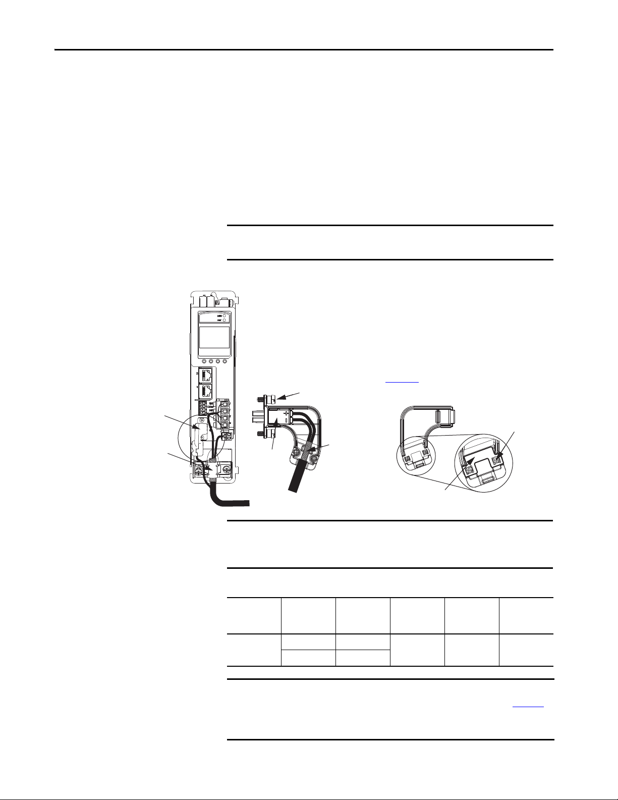
Chapter 5 Connect the Kinetix 5500 Drive System
Motor Cable
Shield Clamp
Motor Feedback
Connector Kit
2198-KITCON-DSL
Feedback Connector Kit
Conne ctor
Housing
Refer to Kinetix 5500 Feedback Connector
Kit Installation Instructions, publication
2198-IN002
, for connector kit specifications.
Internal
Grounding Plate
Cover Sc rews (2)
Mounting Screws (2)
Exposed Shield
Feedback Cable
(EPWR+, EPWR-)
Cover
Kinetix 5500 Servo Drive
(front view)
2090-CSBM1DF-18AAxx
Motor Cable
Motor Feedback Connections
Single motor-cable feedback connections are made by using the 2198KITCON-DSL feedback connector kit (included with each servo drive).
• 2090-CSxM1DF cables have flying-lead conductors designed
specifically for Kinetix 5500 servo drives.
• 2090-CSxM1DG cables also have flying-lead feedback conductors.
Leads are longer than 2090-CSxM1DF cables to accommodate
Kinetix 5500 or Kinetix 5700 servo drives. However, because the leads
are longer, extra service loops are required with Kinetix 5500 drives.
IMPORTANT When using the 2198-KITCON-DSL feedback connector kit, the ambient
temperature for the Kinetix 5500 drive enclosure is 0…50 °C (32…122 °F).
Figure 52 - MF Connector Wiring
IMPORTANT Cable preparation and positioning that provides a high-frequency bond
between the shield braid and grounding plate is required to optimize system
performance.
Table 42 - Motor Feedback (MF) Connector Specifications
90 Rockwell Automation Publication 2198-UM001I-EN-P - May 2019
Drive Cat. No. Pin
2198-Hxxx-ERSx
IMPORTANT The feedback bundle in 2090-CSxM1DF-18AAxx motor cables (typically used
MF-1 D+/Blue
MF-2 D-/White/Blue
with frame 1 drives) route around the shield clamp (as shown in Figure 52
The feedback bundle in 14 and 10 AWG cables (typically used with frame 2
and 3 drives) route with the power and brake wires inside the cable shield.
Signal/
Wire Color
Wire Size
AWG
22 10.0 (0.39) 0.4 (3.5)
Strip Length
mm (in.)
Cover Screw
Tor que V alue
N•m (lb•in)
).
Page 91

Connect the Kinetix 5500 Drive System Chapter 5
Motor Cable
Shield Clamp
2198-KITCON-DSL
Motor Feedback
Connector Kit
Motor Power
(MP) Connector
Motor Brake
(BC) Connector
Exposed shield braid
under clamp.
Shield Clamp Screws (2)
2.0 N•m (17.7 lb•in), max
Kinetix 5500 Servo Drives,
Frame 1 or 2, Front View
(frame 1 is shown)
Feedback cable routed
around the shield clamp.
2090-CSBM1DF-18AAxx
Single Motor Cable
Retention Screw
(loosen, do not remove)
18 AWG Cable Installation
Apply the Single Motor-cable Shield Clamp
Factory-supplied 2090-Series single motor cables are shielded, and the braided
cable shield must terminate at the drive during installation. A small portion of
the cable jacket has been removed to expose the shield braid. The exposed area
must be clamped (with the clamp provided) at the bottom front of the drive.
SHOCK HAZARD: To avoid hazard of electrical shock, make sure shielded
power cables are grounded according to recommendations.
TIP Cables for Kinetix VP motors (catalog numbers 2090-CBxM1DF-18AAxx) do not
route the feedback bundle under the shield clamp. The same cables with 14 or
10 AWG conductors have the feedback bundle within the cable shield braid.
This procedure assumes you have completed wiring your motor power, brake,
and feedback connectors and are ready to apply the cable shield clamp.
Follow these steps to apply the motor cable shield clamp.
1. Loosen the left-side (retention) clamp screw and remove the right-side
screw.
When the drive/motor combination calls for 18 AWG cable, the
feedback cable routes around the motor cable shield clamp.
Rockwell Automation Publication 2198-UM001I-EN-P - May 2019 91
Page 92
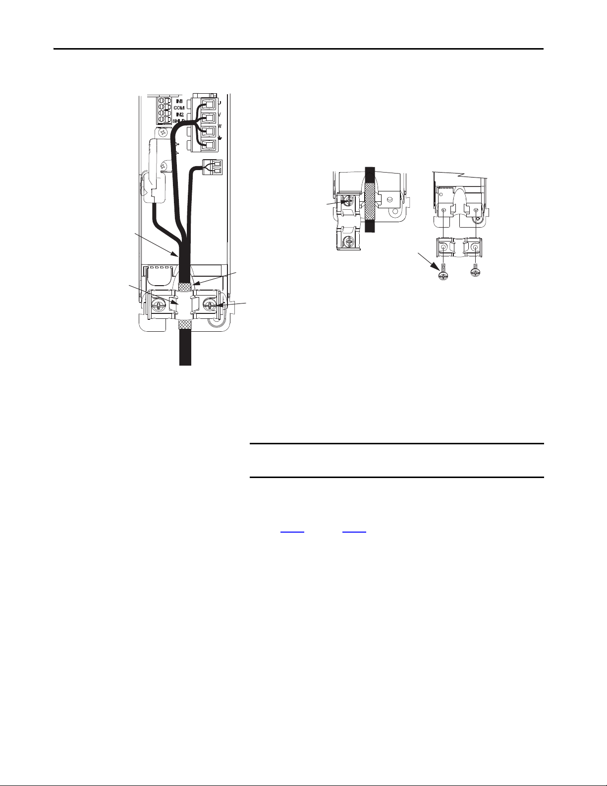
Chapter 5 Connect the Kinetix 5500 Drive System
Motor Cable
Shield Clamp
Motor Power
(MP) Connector
Motor Brake
(BC) Connector
Exposed shield braid
under clamp.
Shield Clamp Screws (2)
Feedback cable routed
within the shield braid.
Kinetix 5500 Servo Drives,
Frame 2 or 3, Front View
(frame 2 is shown)
2198-KITCON-DSL
Motor Feedback
Connector Kit
Retention Screw
(loosen, do not remove)
Clamp features apply to all
frame sizes.
Torque clamp screws to
2.0 N•m (17.7 lb•in), max
2090-CSBM1DF-14AAxx
Single Motor Cable
Servo Drive
Shield Clamp
Clamp Screws
2.0 N•m (17.7 lb•in)
Retention
Screw
14 and 10 AWG Cable Installation
Wire Other Allen-Bradley Motors and Actuators
When the drive/motor combination calls for 14 or 10 AWG cable, the
feedback cable routes along with the power and brake wiring.
2. Position the exposed portion of the cable shield directly in line with the
clamp.
IMPORTANT Loosen the retention screw, if needed, until you can start threading
3. Tighten each screw a few turns at a time until the maximum torque
value of 2.0 N•m (17.7 lb•in) is achieved.
4. Repeat step 1
Kinetix 5500 drives are also compatible with many other Allen-Bradley®
motors and actuators, however the 2198-H2DCK Hiperface-to-DSL feedback
converter kit is required for converting the 15-pin Hiperface feedback signals
to 2-pin DSL feedback signals.
Follow these guidelines when 2090-CPxM7DF (power/brake) cables and
2090-CFBM7DF (feedback) cables are used in a new installation or reused in
an existing installation with Kinetix 5500 servo drives. MP-Series™ servo
motors and actuators have separate connectors for 2090-CPxM7DF power/
brake cables and 2090-CFBM7DF feedback cables.
both clamp screws with the cable shield under the clamp.
through step 3 for each drive in multi-axis configurations.
92 Rockwell Automation Publication 2198-UM001I-EN-P - May 2019
Page 93
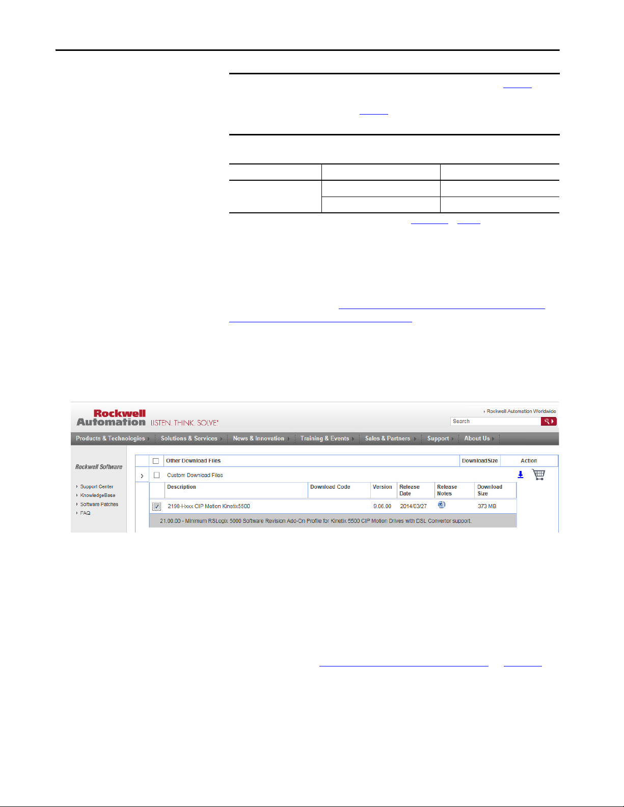
Connect the Kinetix 5500 Drive System Chapter 5
IMPORTANT To configure these additional motors and actuators (see Tab le 4 4
) with
your Kinetix 5500 servo drive, you must have drive firmware 2.002 or
later. Refer to Tab le 4 3
to determine if you need to install the
Kinetix 5500 Add-on Profile.
Table 43 - AOP Installation Requirement
Drive Firmware Revision Logix Designer Application Version Kinetix 5500 AOP Needed?
2.002 or later
(1) If you are planning to use drive firmware revision 4.001 or later, see Versi on Hi stor y on page 113.
21.00 Yes
21.03 or later
(1)
No
Install the Kinetix 5500 Add-On Profile
Add-On profiles (AOP) are available for download at the Custom Downloads
Add-On Profiles website: https://download.rockwellautomation.com/esd/
download.aspx?downloadid=addonprofiles
Follow these steps to download the Kinetix 5500 Add-On profile.
1. Login to the Custom Download Add-On Profiles website.
The Custom Download Files dialog box opens.
2. Check AOP for 2198-Hxxx CIP Motion Kinetix5500.
3. Click Download Now and accept the user license agreement.
If prompted to install the Download Manager, allow the installation.
4. Click the Add-On Profile icon and follow the download instructions.
5. Extract the AOP zip file and run Setup.
To access AOP downloads by using the Product Compatibility Download
Center (PCDC), see Install the Kinetix 5500 Add-On Profile
on page 114.
Rockwell Automation Publication 2198-UM001I-EN-P - May 2019 93
Page 94
Chapter 5 Connect the Kinetix 5500 Drive System
Motor Power and Brake Connections
The motors and actuators in Ta b l e 4 4 have separate power/brake and feedback
cables. The motor power/brake cable attaches to the cable clamp on the drive
and the power/brake conductors attach to the MP and BC connectors,
respectively.
Table 44 - Current Motor Power Cable Compatibility
Motor/Actuator Cat. No.
MPL-A/B15xxx-xx7xAA, MPL-A/B2xxx-xx7xAA,
MPL-A/B3xxx-xx7xAA, MPL-A/B4xxx-xx7xAA,
MPL-A/B45xxx-xx7xAA, MPL-A/B5xxx-xx7xAA,
MPL-B6xxx-xx7xAA
MPM-A/Bxxxx, MPF-A/Bxxxx, MPS-A/Bxxxx
MPAS-A/Bxxxx1-V05SxA, MPAS-A/Bxxxx2-V20SxA
MPAI-A/Bxxxx, MPAR-A/B3xxx,
MPAR-A/B1xxx and MPAR-A/B2xxx (series B)
LDAT-Sxxxxxx-xDx N/A
(1) The 2198-H2DCK (series B or later) feedback converter kit is required.
(2) Refer to the Kinetix Motion Accessories Specifications Technical Data, publication KNX-TD004, for cable specifications.
(1)
Motor Power Cat. No.
(with brake wires)
2090-CPBM7DF-xxAAxx
(standard) or
2090-CPBM7DF-xxAFxx
(continuous-flex)
(2)
Motor Power Cat. No.
(without brake wires)
2090-CPWM7DF-xxAAxx
(standard) or
2090-CPWM7DF-xxAFxx
(continuous-flex)
(2)
Refer to Motor Power Connections on page 88 and Motor Brake Connections
on page 89
Table 45 - Legacy Motor Power Cables
Motor Cable Description Motor Power Cat. No.
Standard
Continuous-flex
Table 46 - Induction Motor Power Cable Specifications
Cable Manufacturer Cable Series Voltage Rating Temperature Rating
Belden 29500-29507
SAB VFD XLPE TR
for the MP and BC connector specifications.
Power/brake, threaded 2090-XXNPMF-xxSxx
Power-only, bayonet 2090-XXNPMP-xxSxx
Power/brake, threaded 2090-CPBM4DF-xxAFxx
Power-only, threaded 2090-CPWM4DF-xxAFxx
Power-only, bayonet 2090-XXTPMP-xxSxx
600V 90 °C (194 °F)Lapp Group ÖLFEX VFD XL
94 Rockwell Automation Publication 2198-UM001I-EN-P - May 2019
Page 95
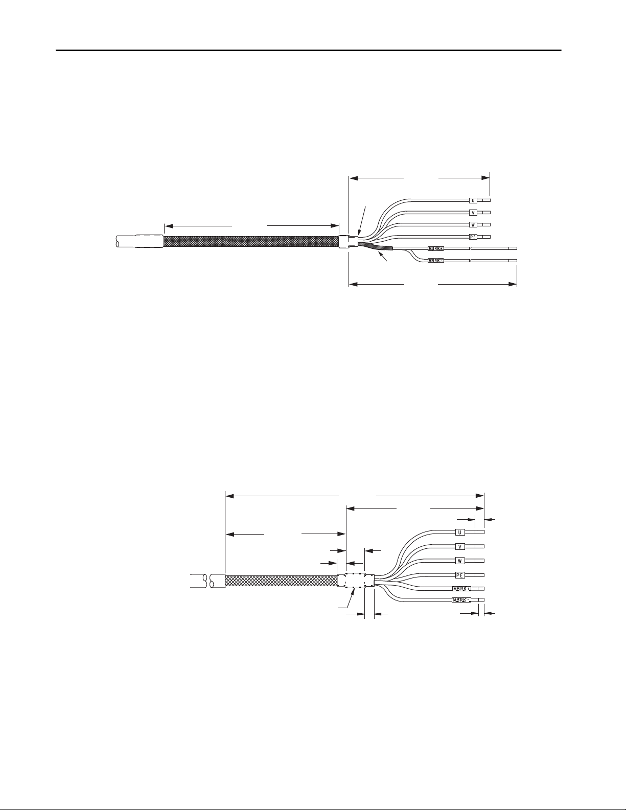
Connect the Kinetix 5500 Drive System Chapter 5
635 (25)
102 (4.0)
150 (5.9)
Dimensions are in mm (in.)
Power Conductors
Brake
Condu ctors
MP-Series Motors
and Actuators
Brake Shield (remove)
Edge of
Heat Shrink
Overall Cable Shield
305 (12.0)
71 (2.80)
12.7 (0.50)
5.0 (0.20)
5.0 (0.20)
234 (9.20)
15.0 (0.59)
8.0 (0.31)
Dimensions are in mm (in.)
Power Conductors
Brake
Conduc tors
MP-Series Motors
and Actuators
Heat Shrink
Overall Cable Shield
Motor Power/Brake Cable Series Change
Motor power and brake conductors on 2090-CPBM7DF (series A) cables have
the following dimensions from the factory. If your cable is reused from an
existing application, the actual conductor lengths could be slightly different.
Figure 53 - 2090-CPBM7DF (series A) Power/brake Cable Dimensions
To reuse your existing (series A) Bulletin 2090 cables with Kinetix 5500 drives,
some preparation is necessary so that the cable shield, conductor, and strip
lengths are correct. Follow these cable preparation guidelines:
• Trim the shield flush so that no strands can short to adjacent terminals.
• Measure the conductor lengths and include a service loop.
• Remove just enough insulation to provide the proper strip length.
Motor power and brake conductors on 2090-CPBM7DF (series B) 12 and 10
AWG standard (non-flex) cables provide drive-end shield braid and conductor
preparation modified for compatibility with multiple Kinetix servo drive
families, including Kinetix 5500 drives.
Figure 54 - 2090-CPBM7DF (series B, 10 or 12 AWG) Power/brake Cable Dimensions
Rockwell Automation Publication 2198-UM001I-EN-P - May 2019 95
Page 96

Chapter 5 Connect the Kinetix 5500 Drive System
Maximum Cable Lengths
Combined motor cable length for all axes on the same DC bus must not
exceed 250 m (820 ft). The maximum drive-to-motor cable length for
Kinetix 5500 drives and motor/actuator combinations with 2090-CxxM7DF
cables is 20 m (65.6 ft); however, you can replace the existing motor power/
brake cable with a 2090-CSBM1DF or 2090-CSBM1DG single motor cable
to extend the length up to 50 m (164 ft).
IMPORTANT The option to replace 2090-CPBM7DF power/brake cables with
2090-CSBM1DF/DG single cables applies to only 18 and 14 AWG single
cables. 2090-CSxM1Dx-10Axxx (10 AWG/M40 connector) single cables are
not compatible with 2090-CPBM7DF-10Axxx (10 AWG/M40 connector)
power/brake cables.
When replacing your existing motor power/brake cable with a
2090-CSBM1DF/DG single motor cable, only the motor power and brake
conductors are used. Cut off the feedback conductors in the single motor
cable and reuse the existing 2090-Series feedback cable.
Motor Power/Brake Cable Preparation
2090-CPBM7DF (series B) cables are available with 12 and 10 AWG motorpower conductor sizes. So, 14 AWG cables used on frame 3 drives, which are
physically taller, require preparation.
Cable Preparation for Frame 1 and Frame 2 Drives
For frame 1 and frame 2 drives, the 2090-CPBM7DF (16 and 14 AWG) power
conductor length, 102 mm (4.0 in.), is sufficiently long to reach the MP
connector plug and provide adequate stress relief.
The brake conductor length, 635 mm (25 in.), is much longer than necessary.
We recommend that you measure 163 mm (6.4 in.) from the edge of the cable
jacket (that is covered by heat shrink) and trim off the rest.
Refer to Figure 56
lengths and torque values, refer to Ta b l e 4 0
Cable Preparation for Frame 3 Drives
2090-CPBM7DF (series B) 12 and 10 AWG cables are designed for use with
Kinetix 5500 drives and do not require any modifications.
and on page 99 for a typical installation example. For strip
on page 89.
For frame 3 drives, 2090-CPBM7DF (14 AWG) cables, and 12 and 10 AWG
(series A) cables, the overall length of the cable preparation area needs to be
increased for the motor power conductors to reach the MP connector and also
provide a proper service loop.
96 Rockwell Automation Publication 2198-UM001I-EN-P - May 2019
Page 97

Connect the Kinetix 5500 Drive System Chapter 5
Dimensions are in mm (in.)
Motor Conductors
Brake
Condu ctors
(1)
Electrical Tape
or Heat Shrink
8.0 (0.31) Frame 1 and 2 drives
10.0 (0.39) Frame 3 drives
Follow these steps to prepare your existing 14 AWG cables, and 12 and
10 AWG (series A) cables.
1. Remove a total of 325 mm (12.8 in.) of cable jacket from your existing
cable.
This exposes additional cable shield.
2. Remove all but 63.5 mm (2.5 in.) of the shield.
3. Cover 12.5 mm (0.5 in.) of the shield ends and an equal length of the
conductors with 25 mm (1.0 in.) of electrical tape or heat shrink.
Do the same on the other side of the cable shield. This keeps the shield
ends from fraying and holds the conductors together.
4. Cut the brake conductors back to 163 mm (6.4 in.) and trim the shield
braid at the base of the jacket.
The shield braid covering the brake conductors is not needed.
5. Remove the specified length of insulation from the end of each wire.
This example applies to existing 2090-CPBM7DF (14 AWG) cables, and 12
and 10 AWG (series A) cables. If you are using a 2090-CSBM1DF/DG single
motor cable, you can remove the shield braid covering the brake conductors.
Figure 55 - Power/brake Cable (14, 12, and 10 AWG)
325 (12.8)
262 (10.3)
25.0 (1.0)
284 (11.2)
155 (6.1)
221 (8.7)
7.0 (0.28)
51.0 (2.0)
(1) The overall shield braid covering the brake conductors can be removed.
Refer to Figure 56 and on page 99 for a typical installation example. For strip
lengths and torque values, refer to Ta b l e 4 0
on page 89.
Rockwell Automation Publication 2198-UM001I-EN-P - May 2019 97
Page 98

Chapter 5 Connect the Kinetix 5500 Drive System
Apply the Motor Power/brake Shield Clamp
The power/brake cable shield attaches to the drive cable clamp. A clamp spacer
is included with the 2198-H2DCK feedback converter kit for cable diameters
that are too small for a tight fit within the drive clamp alone.
SHOCK HAZARD: To avoid hazard of electrical shock, make sure shielded
power cables are grounded according to recommendations.
Follow these steps to apply the motor power/brake shield clamp.
1. Route the conductors with service loops to provide stress relief to the
motor power and brake conductors.
2. Make sure the cable clamp tightens around the cable shield and provides
a good bond between the cable shield and the drive chassis.
IMPORTANT Loosen the retention screw, if needed, until you can start threading
both clamp screws with the cable shield under the clamp.
3. Tighten each screw, a few turns at a time, until the maximum torque
value of 2.0 N•m (17.7 lb•in) is achieved.
IMPORTANT If the power/brake cable shield has a loose fit inside the shield clamp,
insert the clamp spacer between the shield clamp and the drive to
reduce the clamp diameter. When the clamp screws are tight, 2.0 N•m
(17.7 lb•in), the result must be a high-frequency bond between the
cable shield and the drive chassis.
Refer to Figure 56
on page 99 for a cable-clamp attachment illustration.
98 Rockwell Automation Publication 2198-UM001I-EN-P - May 2019
Page 99

Figure 56 - Cable Clamp Attachment
Clamp Compressed
Around Shield
(no spacer required)
Insert the clamp spacer when
the cable diameter is smaller
than the drive clamp alone.
Servo Drive
Clamp Spacer (if needed)
(1)
Shield Clamp
Clamp Screws
2.0 N•m (17.7 lb•in)
Service Loops
Frame 1
Servo Drive
Frame 2
Servo Drive
Frame 3
Servo Drive
Clamp Spacer Added
(small diameter cable)
Retention
Screw
Retention Screw
(loosen, do not remove)
Clamp features apply to all
frame sizes.
Connect the Kinetix 5500 Drive System Chapter 5
Rockwell Automation Publication 2198-UM001I-EN-P - May 2019 99
(1) The clamp spacer is included with the Hiperface-to-DSL feedback converter kit, catalog number 2198-H2DCK.
Page 100

Chapter 5 Connect the Kinetix 5500 Drive System
Motor Feedback Connections
The feedback cable attaches to the 2198-H2DCK converter kit and is wired to
the 10-pin connector. Bulletin 2090 feedback cables require preparation to
make sure the shield clamp attaches properly and conductors route smoothly to
the 10-pin connector terminals.
IMPORTANT When using the 2198-H2DCK feedback connector kit and Bulletin 2090
feedback cables listed in Tab le 4 7
for the Kinetix 5500 drive enclosure is derated to 0…40 °C (32…104 °F).
All of the current and legacy feedback cables listed below are compatible with
the 2198-H2DCK (series B or later) converter kit.
IMPORTANT Only Allen-Bradley motors and actuators with single-turn or multi-turn
high-resolution absolute encoders are compatible.
Table 47 - Motor Feedback Cable Compatibility
Motor/Actuator Family
MP-Series low-inertia motors
MP-Series medium-inertia motors MPM-A/Bxxxx-S/M
MP-Series food-grade motors MPF-A/Bxxxx-S/M
MP-Series stainless-steel motors MPS-A/Bxxxxx-S/M
MP-Series integrated linear stages
MP-Series electric cylinders
MP-Series heavy-duty electric
cylinders
LDAT-Series linear thrusters LDAT-Sxxxxxx-xDx
(1) The 2198-H2DCK (series B or later) feedback converter kit is required.
Motor/Actuator
Cat. No.
MPL-A/B15xxx-V/Ex7xAA
MPL-A/B2xxx-V/Ex7xAA
MPL-A/B3xxx-S/Mx7xAA
MPL-A/B4xxx-S/Mx7xAA
MPL-A/B45xxx-S/Mx7xAA
MPL-A/B5xxx-S/Mx7xAA
MPL-B6xxx-S/Mx7xAA
MPAS-A/Bxxxx1-V05SxA
MPAS-A/Bxxxx2-V20SxA
MPAR-A/B1xxxx-V and MPAR-A/B2xxxx-V
(series B)
MPAR-A/B3xxxx-M
xxxxxM3
MPAI-A/B
or Tab le 4 8, the ambient temperature
(1)
Feedback Cable
Cat. No.
2090-CFBM7DF-CEAAxx
2090-CFBM7DD-CEAAxx
2090-CFBM7DF-CERAxx
(standard) or
2090-CFBM7DF-CEAFxx
2090-CFBM7DD-CEAFxx
2090-CFBM7DF-CDAFxx
(continuous-flex)
Table 48 - Legacy Motor Feedback Cables
Motor Cable Description Feedback Cable Cat. No.
Encoder feedback, threaded
Standard
Encoder feedback, bayonet
Continuous-flex
100 Rockwell Automation Publication 2198-UM001I-EN-P - May 2019
Encoder feedback, bayonet 2090-XXTFMP-Sxx
Encoder feedback, threaded 2090-CFBM4DF-CDAFxx
2090-XXNFMF-Sxx
2090-UXNFBMF-Sxx
2090-UXNFBMP-Sxx
2090-XXNFMP-Sxx
 Loading...