

Allen-Bradley 2198-DB127-F, 2198-DB111-F, 2198-DB335-F, 2198-DB310-F, 2198-DB324-F Installation Instructions Manual
...Page 1
Installation Instructions
Original Instructions
Kinetix 5100 AC Line Filter
Catalog Numbers 2198-DB111-F, 2198-DB127-F, 2198-DB310-F, 2198-DB324-F,
2198-DB335-F, 2198-DB356-F
Topic Page
Before You Begin 1
Install the AC Line Filter 2
Wire the AC Line Filter 2
AC Line Filter Dimensions 4
Additional Resources 7
This publication provides installation instructions for the AC line filters used with Kinetix® 5100
servo drives. Use these instructions for installing and wiring your AC line filter. For more
information on installing and wiring your AC line filter, see Kinetix 5100 Single-axis
EtherNet/IP™ Servo Drives Users Manual, publication 2198-UM004
.
Before You Begin
For general guidelines when laying out your panel and mounting your AC line filter, refer to the
System Design for Control of Electrical Noise Reference Manual, publication GMC-RM001.
For guidelines specific to your application, refer to the Kinetix 5100 Single-axis EtherNet/IP
Servo Drives Users Manual, publication 2198-UM004
ATT EN TI ON : To avoid personal injury or damage to equipment due to hazardous voltages, follow
these guidelines when installing your AC line filter. NEC and local regulations always take
precedence.
• Disconnect mains power before installation.
• Verify that the rated voltage is compatible with the local supply voltage.
• Connect the earth ground connection first when you make connections.
.
Page 2

Kinetix 5100 AC Line Filter
Install the AC Line Filter
Mount the line filter to the cabinet panel with hardware as specified in this table.
Cat. No. Mounting Bolts
2198-DB111-F
2198-DB127-F
2198-DB310-F
2198-DB324-F
2198-DB335-F
2198-DB356-F
M5 (#10-24) 1.6…2.0 (13.9…17.70)
Tor que Valu e
N•m (lb•in)
See the System Design for Control of Electrical Noise Reference Manual, publication
GMC-RM001,
for techniques on how to make proper high-frequency (HF) bonds to improve
overall system performance.
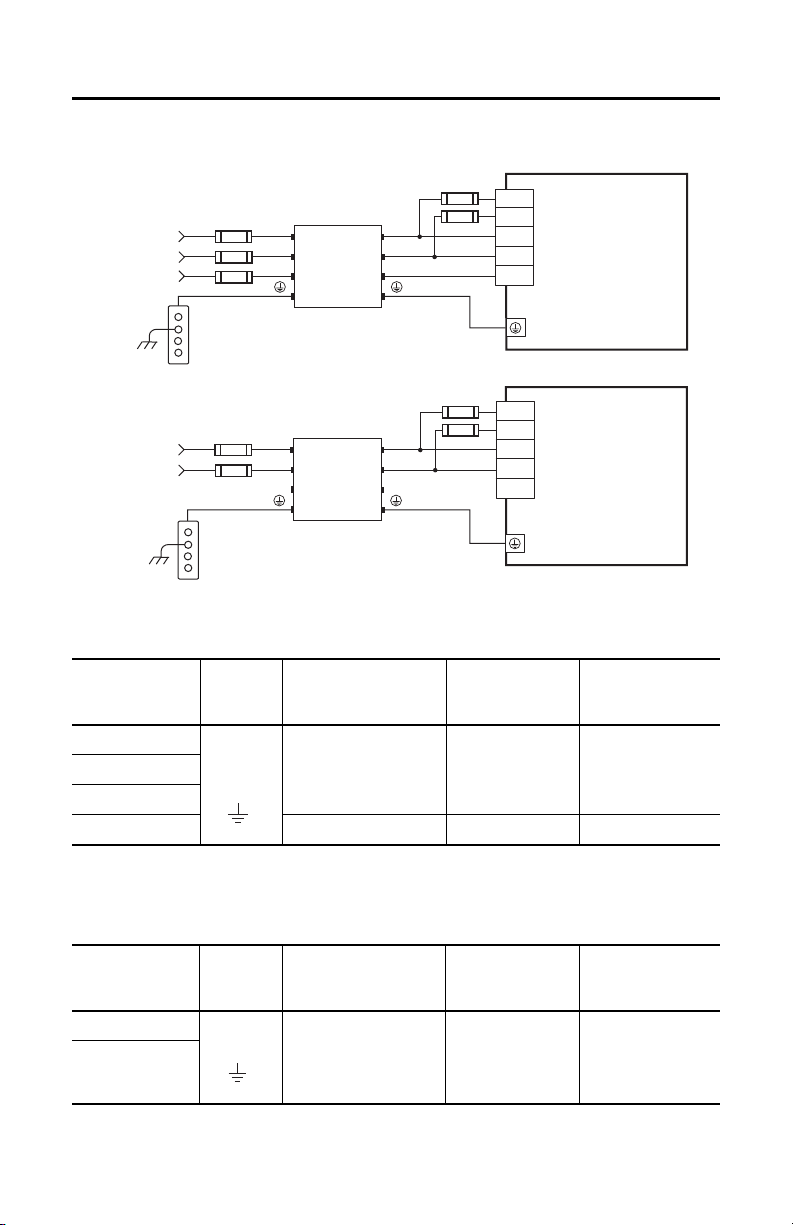
Wire the AC Line Filter
Wire by using copper with 75 °C (167 °F) minimum rating. The phase of main AC power is
arbitrary and earth ground connection is required for safe and proper operation.
IMPORTANT The National Electrical Code and local electrical codes take precedence over the values and
methods provided.
2 Rockwell Automation Publication 2198-IN017A-EN-P - July 2019
Page 3
Kinetix 5100 AC Line Filter
L1C
L2C
L1
L2
L3
L1
L2
L3
L1’
L2’
L3’
230V
L1
L2
120/230V
L1C
L2C
L1
L2
L3
Bonded Cabinet
Ground Bar
2198-DB1xxF
AC Lin e Filter
Mains AC Input
Line
Load
Bonded Cabinet
Ground Bar
2198-DBxxx-F
AC Line Filter
Mains AC Input
Kinetix 5100 drive input
power connections for
three-phase operation.
Line
Load
Kinetix 5100 drive input
power connections for
single-phase operation.
Circuit
Protection
Circuit
Protection
Circuit
Protection
Circuit
Protection
L1
L2
L3
L1
L2
Wiring Examples for the AC Line Filter
Three-Phase Wiring Specifications
(AWG)
(1)
(1)
AC Line Filter
Strip Length
mm (in.)
AC Line Filter
Strip Length
mm (in.)
Line Filter
Cat. No.
Connects to
Ter mi nal s
Recommended
Wire Size
2
mm
2198-DB310-F
0.8…8.4 (18…8) 11.0 (0.43) 1.8 (15.58)2198-DB324-F
2198-DB335-F
2198-DB356-F 2.5…33.6 (14…3) 15.0 (0.59) 3.4 (30.1)
(1) The actual gauge of the input p ower wiring depends on the system configuration. Consult your machine builder, the NEC, and applicable local
Single-Phase Wiring Specifications
Line Filter
Cat. No.
codes.
Connects to
Ter min al s
Recommended
Wire Size
2
mm
(AWG)
2198-DB111-F
2198-DB127-F
(1) The actual gauge of the input p ower wiring depends on the system configuration. Consult your machine builder, the NEC, and applicable local
codes.
Rockwell Automation Publication 2198-IN017A-EN-P - July 2019 3
0.8…8.4 (18…8) 11.0 (0.43) 1.8 (15.58)
Ter mi nal
Tor que Valu es
N•m (lb•in)
Ter min al
Tor que Valu es
N•m (lb•in)
Page 4

Kinetix 5100 AC Line Filter
54.0
(2.13)
6.5
(0.26)
223.0
(8.78)
234.0
(9.21)
72.0
(2.83)
54.0
(2.13)
5.5
(0.22)
270
(10.63)
(Minimum)
30.0
(1.18)
5.5
(0.22)
55.0
(2.17)
223.0
(8.78)
23.0
(0.91)
20.0
(0.79)
5.5
(0.22)
5.5
(0.22)
Dimensions are in mm (in.).
AC Line Filter Dimensions
AC Line Filter Dimensions (Catalog numbers 2198-DB111-F and 2198-DB310-F)
4 Rockwell Automation Publication 2198-IN017A-EN-P - July 2019
Page 5

Kinetix 5100 AC Line Filter
275.0
(10.82)
263.0
(10.35)
5.5
(0.22)
76.0
(2.99)
109.0
(4.29)
76.0
(2.99)
270
(10.6)
5.5
(0.22)
5.5
(0.22)
29.1
(1.15)
28.0
(1.15)
86.0
(3.39)
263.0
(10.35)
Dimensions are in mm (in.).
130.0
(5.12)
90.0
(3.54)
80.0
(3.15)
5.5
(0.22)
116.0
(4.57)
310.0
(12.20)
298.0
(11.73)
247.0
(9.72)
340
(13.4)
5.5
(0.22)
90.0
(3.54)
33.0
(1.30)
28.0
(1.10)
5.5
(0.22)
298.0
(11.73)
(Minimum)
Dimensions are in mm (in.).
AC Line Filter Dimensions (Catalog numbers 2198-DB127-F and 2198-DB324-F)
AC Line Filter Dimensions (Catalog number 2198-DB335-F)
Rockwell Automation Publication 2198-IN017A-EN-P - July 2019 5
Page 6

Kinetix 5100 AC Line Filter
5.5
(0.22)
5.5
(0.22)
5.5
(0.22)
155.0
(6.10)
110.0
(4.33)
390.0
(15.35)
375.0
(14.76)
28.0
(1.10)
33.0
(1.30)
33.0
(1.30)
28.0
(1.10)
80.0
(1.97)
375.0
(14.76)
Dimensions are in mm (in.).
AC Line Filter Dimensions (Catalog number 2198-DB356-F)
AC Line Filter Specifications
Cat. No.
2198-DB111-F 95…132V AC or
2198-DB127-F 27 15.5 24.0 1.80 (3.968)
2198-DB310-F
2198-DB324-F 24 29.0 1.0 1.95 (3.968)
2198-DB335-F 35 30.0 0.5 2.90 (6.393)
2198-DB356-F 56 57.0 0.5 4.00 (8.818)
6 Rockwell Automation Publication 2198-IN017A-EN-P - July 2019
Volta ge
Rating
170…253V AC
single-phase
170…253V AC
three-phase
Current Rating
A @ 50 °C (122 °F)
Power Loss
W
Leakage
Current
mA
11 4.9 26.0 1.05 (2.314)
Weigh t, approx
kg (lb)
10 14.0 1.0 1.10 (2.425)
Operating
Temp era tur e
-20…+50 °C
(-4…+122 °F)
Page 7

Kinetix 5100 AC Line Filter
Additional Resources
These documents contain additional information concerning related products from Rockwell
Automation.
Resource Description
Provides product specifications for the Kinetix Integrated
Kinetix Servo Drives Specifications Technical Data,
publication KNX-TD003
Kinetix Motion Accessories Specifications Technical Data,
publication KNX-TD004
Kinetix 5100 Single-axis EtherNet/IP Servo Drives Users
Manual, publication 2198-UM004
Industrial Automation Wiring and Grounding Guidelines,
publication 1770-4.1
Product Certifications website: rok.auto/certifications
You can view or download publications at http://www.rockwellautomation.com/global/
literature-library/overview.page.
Motion over EtherNet/IP network, Integrated Motion over
Sercos interface, EtherNet/IP networking, and component
servo drive families.
Provides product specifications for Bulletin 2090 motor and
interface cables, low-profile connector kits, drive power
components, and other servo drive accessory items.
Information on how to install, configure, start, and
troubleshoot your Kinetix 5100 servo drive system.
Provides general guidelines for installing a Rockwell
Automation industrial system.
Provides declarations of conformity, certificates, and other
certification details.
Rockwell Automation Publication 2198-IN017A-EN-P - July 2019 7
Page 8

Rockwell Otomasyon Ticaret A.Ş., Kar Plaza İş Merkezi E Blok Kat:6 34752 İçerenköy, İstanbul, Tel: +90 (216) 5698400
Rockwell Automation Support
Use the following resources to access support information.
Documentation Feedback
Your comments will help us serve your documentation needs better. If you have any suggestions
on how to improve this document, complete the How Are We Doing? form at http://
literature.rockwellautomation.com/idc/groups/literature/documents/du/ra-du002_-en-e.pdf.
Technical Support
Center
Knowledgebase Articles,
How-to Videos, FAQs, Chat,
User Forums, and Product
Notification Updates.
https://rockwellautomation.custhelp.com/
Local Technical
Support Phone
Numbers
Locate the phone number
for your country.
http://www.rockwellautomation.com/global/support/get-supportnow.page
Direct Dial Codes
Find the Direct Dial Code
for your product. Use the
code to route your call
directly to a techn ical
support engineer.
http://www.rockwellautomation.com/global/support/direct-dial.page
Literature Library
Installation Instructions,
Manuals, Brochures, and
Technical Data.
http://www.rockwellautomation.com/global/literature-library/
overview.page
Product
Compatibility and
Download Center
(PCDC)
Get help determining how
products interact, check
features and capabilities,
and find associated
firmware.
http://www.rockwellautomation.com/global/support/pcdc.page
Rockwell Automation maintains current product environmental information on its webs ite at
http://www.rockwellautomation.com/rockwellautomation/abou t-us/sustainability-ethics/product- environmental-compliance.page
Allen-Bradley, Kinetix, Rockwell Automation, and Rockwell Soft ware are trademarks of Rockwell Automation, Inc.
EtherNet/IP is a trademark of ODVA, Inc.
Trademarks not belonging to Rockwell Automation are property of their respective companies.
Publication 2198-IN017A-EN-P - July 2019
Copyright © 2019 Rockwell Automation, Inc. All rights reserved. Printed in the U.S.A.
.
 Loading...