

Allen-Bradley 2097-V31PR2, 2097-V32PR2, 2097-V32PR0, 2097-V33PR1, 2097-V33PR3 Installation Instructions Manual
...Page 1

Installation Instructions
Kinetix 300 EtherNet/IP Indexing
Servo Drives
Catalog Numbers 2097-V31PR0, 2097-V31PR2, 2097-V32PR0, 2097-V32PR2,
2097-V32PR4, 2097-V33PR1, 2097-V33PR3, 2097-V33PR5, 2097-V33PR6, 2097-V34PR3,
2097-V34PR5, 2097-V34PR6
Top ic Pa ge
About the Kinetix 300 Drives 1
Important User Information 2
Catalog Number Explanation 3
Before You Begin 4
Install the Kinetix 300 Drive 5
Connector Data 7
Power Wiring Requirements 12
Motor Overload Protection 15
Additional Resources 16
About the Kinetix 300 Drives
Kinetix® 300 EtherNet/IP indexing servo drives provide an Ethernet-enabled solution for
applications with output power requirements in the range of 0.4…3.0 kW (2…12 A rms).
Refer to the Kinetix 300 EtherNet/IP Indexing Servo Drives User Manual, publication
2097-UM001
integration with ControlLogix®, CompactLogix™, or MicroLogix™ controller platforms.
, for detailed information on wiring, applying power, troubleshooting, and
Page 2
2 Kinetix 300 EtherNet/IP Indexing Servo Drive
IMPORTANT
Important User Information
Read this document and the documents listed in the additional resources section about installation, configuration, and operation of
this equipment before you install, configure, operate, or maintain this product. Users are required to familiarize themselves with
installation and wiring instructions in addition to requirements of all applicable codes, laws, and standards.
Activities including installation, adjustments, putting into service, use, assembly, disassembly, and maintenance are required to be
carried out by suitably trained personnel in accordance with applicable code of practice.
If this equipment is used in a manner not specified by the manufacturer, the protection provided by the equipment may be impaired.
In no event will Rockwell Automation, Inc. be responsible or liable for indirect or consequential damages resulting from the use or
application of this equipment.
The examples and diagrams in this manual are included solely for illustrative purposes. Because of the many variables and
requ irement s assoc iated wi th any par ticula r insta llation , Rockwell Auto mation, Inc . canno t assum e respon sibility or l iabili ty for actual
use based on the examples and diagrams.
No patent liability is assumed by Rockwell Automation, Inc. with respect to use of information, circuits, equipment, or software
described in this manual.
Reproduction of the contents of this manual, in whole or in part, without written permission of Rockwell Automation, Inc., is
prohibited.
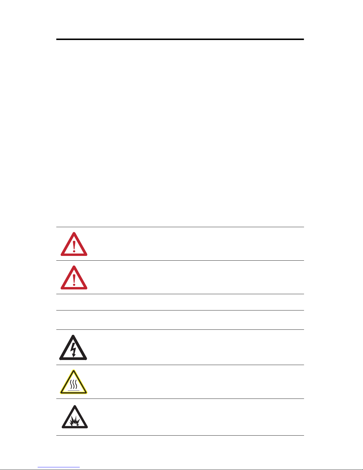
Throughout this manual, when necessary, we use notes to make you aware of safety considerations.
WARNING: Identifies information about practices or circumstances that can cause an explosion in a hazardous
environment, which may lead to personal injury or death, property damage, or economic loss.
ATTENTION: Identifies information about practices or circumstances that can lead to personal injury or death,
property damage, or economic loss. Attentions help you identify a hazard, avoid a hazard, and recognize the
consequence.
Identifies information that is critical for successful application and understanding of the product.
Labels may also be on or inside the equipment to provide specific precautions.
SHOCK HAZARD: Labels may be on or inside the equipment, for example, a drive or motor, to alert people that
dangerous voltage may be present.
BURN HAZARD: Labels may be on or inside the equipment, for example, a drive or motor, to alert people that
surfaces may reach dangerous temperatures.
ARC FLASH HAZARD: Labels may be on or inside the equipment, for example, a motor control center, to alert
people to potential Arc Flash. Arc Flash will cause severe injury or death. Wear proper Personal Protective
Equipment (PPE). Follow ALL Regulatory requirements for safe work practices and for Personal Protective
Equipment (PPE).
Rockwell Automation Publication 2097-IN001I-EN-P - July 2013
Page 3
Kinetix 300 EtherNet/IP Indexing Servo Drive 3
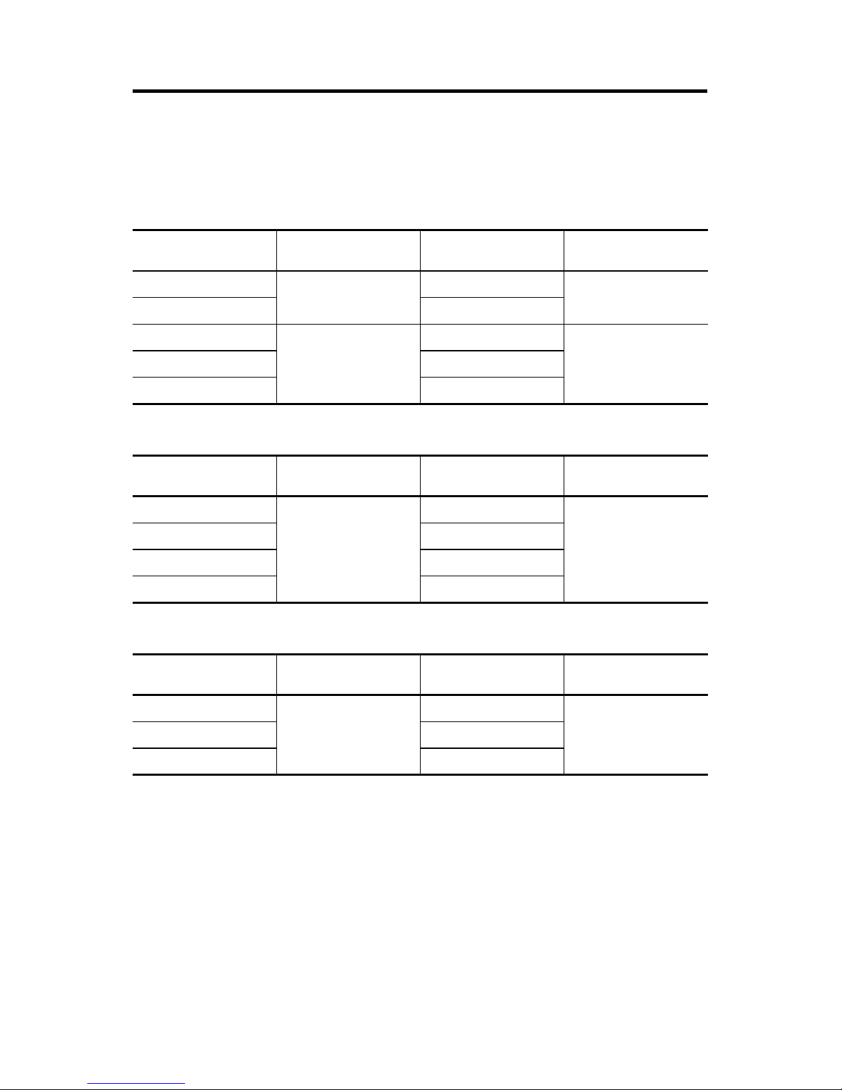
Catalog Number Explanation
This publication applies to the following Kinetix 300 drives.
Kinetix 300 Drives (single-phase)
Cat. No. Input Voltage
2097-V31PR0
2097-V31PR2 5.7
2097-V32PR0
2097-V32PR2 5.7
2097-V32PR4 11.3
120/240V, 1 Ø
240V, 1 Ø
Kinetix 300 Drives (single or three-phase)
Cat. No. Input Voltage
2097-V33PR1
2097-V33PR3 5.7
2097-V33PR5 11.3
2097-V33PR6 17.0
120V, 1 Ø
240V, 1 Ø
240V, 3 Ø
Kinetix 300 Drives (three-phase)
Continuous Output
Current A (0-pk)
2.8
2.8
Continuous Output
Current A (0-pk)
2.8
Featu res
• 120V Doubler mode
• Safe Torque-off
• Integrated AC line filter
• Safe Torque-off
Featu res
Safe Torque-off
Cat. No. Input Voltage
2097-V34PR3
480V, 3 Ø
2097-V34PR6 8.5
Continuous Output
Current A (0-pk)
2.8
Rockwell Automation Publication 2097-IN001I-EN-P - July 2013
Featu res
Safe Torque-off2097-V34PR5 5.7
Page 4

4 Kinetix 300 EtherNet/IP Indexing Servo Drive
TIP
Before You Begin
Remove all packing material, wedges, and braces from within and around the components. After
unpacking, check the item nameplate catalog number against the purchase order.
Parts List
The Kinetix 300 drive ships with the following:
• General-purpose power input (IPD) header, back-up power (BP) header, shunt resistor
and DC bus (BC) header, motor power (MP) header, and safe torque off (STO) header
• A ground clamp that also provides strain relief for motor power cable
• These installation instructions, publication 2097-IN001
The connector kit for motor feedback (catalog number 2090-K2CK-D15M) is not provided.
Replacement connector sets (catalog number 2097-CONN1) are also available.
Refer to the Kinetix Motion Accessories Specifications Technical Data, publication GMC-TD004
for more information.
,
Rockwell Automation Publication 2097-IN001I-EN-P - July 2013
Page 5
Kinetix 300 EtherNet/IP Indexing Servo Drive 5
IMPORTANT
• Additional clearance and different hole patterns are required for side mount
and rear mount AC line filters. See the table and step 2
for more details.
• Additional clearance is required depending on the other accessories installed.
• Additional clearance is required for the cable and wires connected to the top,
front, and bottom of the drive.
• An additional 150 mm (6.0 in.) clearance is required when the drive is
mounted adjacent to noise sensitive equipment or clean wire ways.
Refer to page 6
for Kinetix 300 drive dimensions.
25 mm (1.0 in.) Clearance
for Airflow and Installation
25 mm (1.0 in.) Clearance
for Airflow and Installation
3 mm (0.12 in.)
Side Clearance
3 mm (0.12 in.)
Side Clearance
Install the Kinetix 300 Drive
These procedures assume you have prepared your panel, and understand how to bond your
system. For installation instructions regarding equipment and accessories not included here, refer
to the instructions that came with those products
SHOCK HAZARD: To avoid hazard of electrical shock, perform all mounting and wiring of the
Kinetix 300 drive prior to applying power. Once power is applied, connector terminals can have
voltage present even when not in use.
ATTENTION: Plan the installation of your system so that you can perform all cutting, drilling,
tapping, and welding with the system removed from the enclosure. Because the system is
open-type construction, be careful to keep any metal debris from falling into it. Metal debris or
other foreign matter can become lodged in the circuitry and result in damage to components.
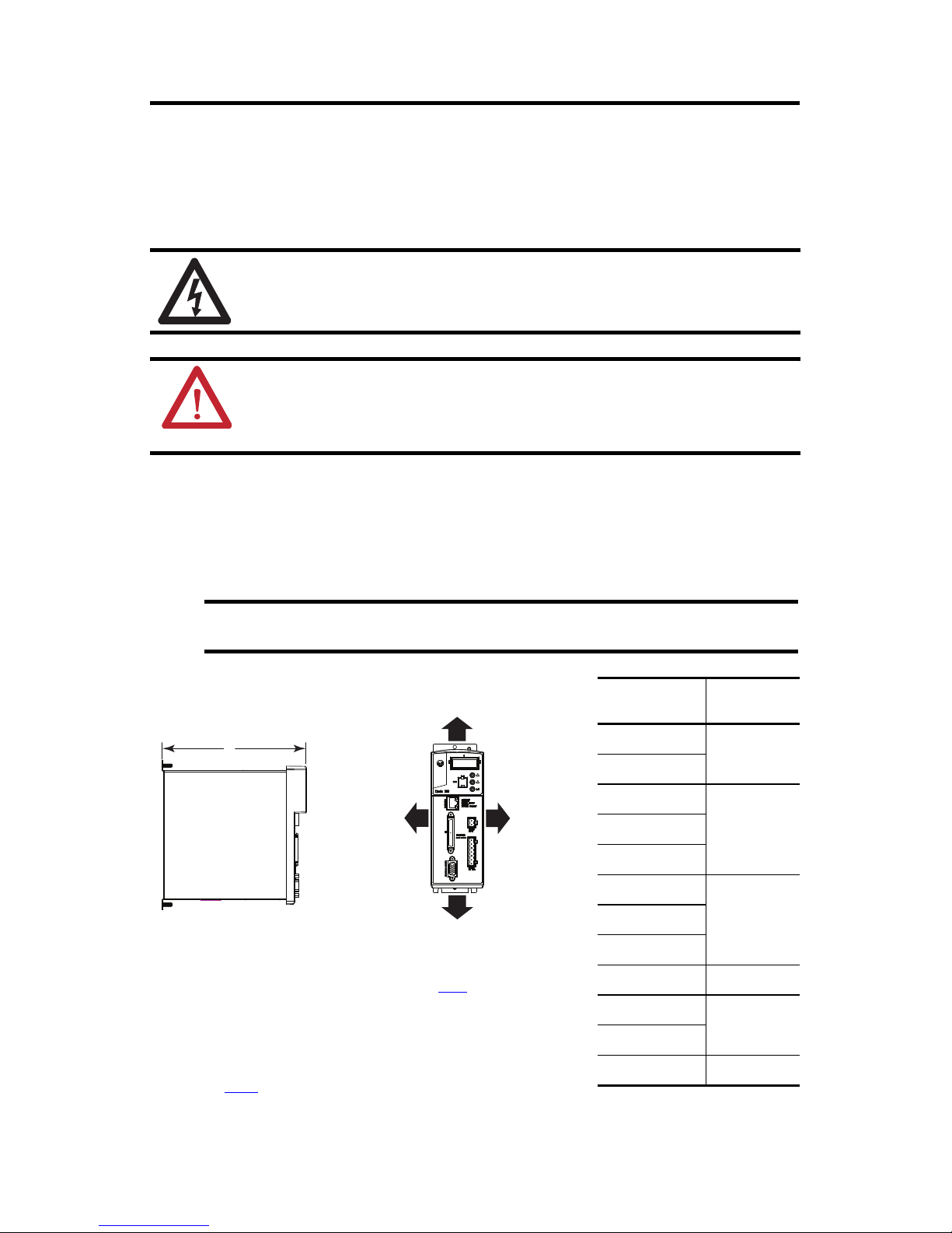
Mount the Kinetix 300 Drive
Follow these steps to mount the drive.
1. Observe these clearance requirements when mounting the drive to the panel.
Mount the module in an upright position as shown. Do not mount the module on
its side.
A
Drive
Cat. No.
2097-V31PR0
2097-V31PR2
2097-V32PR0
2097-V32PR4
2097-V33PR1
2097-V33PR3
2097-V33PR5
2097-V33PR6 230 (9.04)
2097-V34PR3
2097-V34PR5
2097-V34PR6 230 (9.04)
(1) If you are using an AC line filter, add 50
mm (2 in.).
A
mm (in.)
185 (7.29)
230 (9.04)2097-V32PR2
185 (7.29)
185 (7.29)
(1)
(1)
Rockwell Automation Publication 2097-IN001I-EN-P - July 2013
Page 6

6 Kinetix 300 EtherNet/IP Indexing Servo Drive
Dimensions are in mm (in.).
Additional clearance below the connector kit is necessary
to provide the recommended cable-bend radius.
2090-K2CK-D15M
Low-profile Connector Kit for Bulletin
2090 (flying-lead) Feedback Cable
2097-TB1
I/O Terminal
Expansion Block
2. Mount the Kinetix 300 drive to the cabinet sub-panel with an M4 (#6-32) steel machine
screw torqued to 1.1 N•m (9.8 lb•in).
For catalog numbers 2097-V33PR1, 2097-V33PR3, 2097-V33PR5, 2097-V34PR3, and
2097-V34PR5 that use an AC line filter, refer to the AC Line Filter Installation
Instructions, publication 2097-IN003, for the sub-panel mounting hole pattern.
Kinetix 300 Drive Mounting Dimensions
A
5.0
(0.19)
7.1
(0.28)
30.8
(1.21)
9.7
(0.38)
300
182
(7.18)
238
(9.37)
190
(7.50)
6.6
(0.26)
61.0
(2.40)
11.8
(0.46)
38.1
(1.5)
Ø 4.57
(0.18) 3x
B
Cat. No.
Dimensions mm (in.)
AB AB
2097-V31PR0 185.1 (7.29) 68.0 (2.68) 2097-V33PR3 185.1 (7.29) 68.5 (2.70)
2097-V31PR2 185.1 (7.29) 68.5 (2.70) 2097-V33PR5 185.1 (7.29) 94.4 (3.72)
2097-V32PR0 229.6 (9.04) 68.0 (2.68) 2097-V33PR6 229.6 (9.04) 68.0 (2.68)
2097-V32PR2 229.6 (9.04) 68.5 (2.70) 2097-V34PR3 185.1 (7.29) 68.5 (2.70)
2097-V32PR4 229.6 (9.04) 86.8 (3.42) 2097-V34PR5 185.1 (7.29) 94.4 (3.72)
2097-V33PR1 185.1 (7.29) 68.0 (2.68) 2097-V34PR6 229.6 (9.04) 68.0 (2.68)
Rockwell Automation Publication 2097-IN001I-EN-P - July 2013
Cat. No.
Dimensions mm (in.)
Page 7

Kinetix 300 EtherNet/IP Indexing Servo Drive 7
12
3
4
5
8
9
10
11
2
7
6
1
13
15
Top View
(2097-V33PR5
Kinetix 300 drive is shown)
Bottom View
(2097-V33PR5
Kinetix 300 drive is shown)
14
16
Connector Data
Use this illustration to identify the Kinetix 300 drive features and indicators.
Kinetix 300 Drive Features and Indicators
Item Description
1 Ground lug
2 Status and diagnostic display
3 Display-control push buttons (3)
4Back-up power (BP) connector
5 Shunt resistor and DC bus (BC) connector
6 Ground lug
7 Bottom mounting flange
8 Motor feedback (MF) connector
9 I/O (IOD) connector
10 Ethernet communication port (Port 1)
11 Memory module
12 Top mounting flange
13 Mains (IPD) connector
14 Motor power (MP) connector
15 Safe torque off (STO) connector
16 Heat sink (on some models)
Rockwell Automation Publication 2097-IN001I-EN-P - July 2013
Page 8

8 Kinetix 300 EtherNet/IP Indexing Servo Drive
Kinetix 300 Drive Connectors
Designator Description Connector
IPD AC mains input power 4-position plug/header
PORT1 Ethernet communication port RJ45 Ethernet
IOD I/O SCSI 50-pin high-density connector
MF Motor feedback 15-pin high-density D-shell (male)
BP Back-up power 2-pin quick-connect terminal block
BC Shunt resistor and DC bus 5-pin quick-connect terminal block
MP Motor power 6-pin quick-connect terminal block
STO Safe torque off (STO) terminal 6-pin quick-connect terminal block
Mains (IPD) Connector Pinout
IPD Designator Description Signal
L3 AC power in (3-phase models) L3
L2 AC power in L2
L1 AC power in L1
PE Protective earth (ground) PE
Pin Orientation for 8-pin Ethernet Communication Port (port 1)
Port 1 Pin Description Signal
1 Transmit port (+) data terminal + TX
2 Transmit port (-) data terminal - TX
3 Receive port (+) data terminal + RX
4– –
5– –
6 Receive port (-) data terminal - RX
7– –
8– –
1
8
Rockwell Automation Publication 2097-IN001I-EN-P - July 2013
Page 9

Kinetix 300 EtherNet/IP Indexing Servo Drive 9
I/O (IOD) Connector Pinout
IOD Pin Description Signal
1 Master encoder A+/Step+ input MA+
2 Master encoder A-/Step- input MA-
3 Master encoder B+/Direction+ input MB+
4 Master encoder B-/Direction- input MB-
5 Drive logic common GND
6 Reserved –
7 Buffered encoder output: channel A+ BA+
8 Buffered encoder output: channel A- BA-
1
26
9 Buffered encoder output: channel B+ BB+
10 Buffered encoder output: channel B- BB-
11 Buffered encoder output: channel Z+ BZ+
12 Buffered encoder output: channel Z- BZ-
13…21 Reserved –
22 Analog common ACOM
23 Analog output (max 10 mA) AO
24 Positive (+) of analog signal input AIN1+
25 Negative (-) of analog signal input AIN1-
26 Digital input group ACOM terminal IN_A_COM
27 Digital input A1 IN_A1
28 Digital input A2 IN_A2
29 Digital input A3 IN_A3
30 Digital input A4 IN_A4
31 Digital input group BCOM terminal IN_B_COM
25
50
32 Digital input B1 IN_B1
33 Digital input B2 IN_B2
34 Digital input B3 IN_B3
35 Digital input B4 IN_B4
36 Digital input Group CCOM Terminal IN_C_COM
37 Digital input C1 IN_C1
38 Digital input C2 IN_C2
39 Digital input C3 IN_C3
40 Digital input C4 IN_C4
Rockwell Automation Publication 2097-IN001I-EN-P - July 2013
Page 10

10 Kinetix 300 EtherNet/IP Indexing Servo Drive
1
25
50
26
I/O (IOD) Connector Pinout (continued)
IOD Pin Description Signal
41 Ready output collector RDY+
42 Ready output emitter RDY-
43 Programmable output #1 collector OUT1-C
44 Programmable output #1 emitter OUT1-E
45 Programmable output #2 collector OUT2-C
46 Programmable output #2 emitter OUT2-E
47 Programmable output #3 collector OUT3-C
48 Programmable output #3 emitter OUT3-E
49 Programmable output #4 collector OUT4-C
50 Programmable output #4 emitter OUT4-E
Rockwell Automation Publication 2097-IN001I-EN-P - July 2013
Page 11

Kinetix 300 EtherNet/IP Indexing Servo Drive 11
Pin 11
Pin 6
Pin 15
Pin 1
Pin 10
Pin 5
Motor Feedback (MF) Connector Pinout
MF Pin Description Signal
1
2
3
4
5
Sine differential input+
AM+ differential input+
Sine differential inputAM- differential input-
Cosine differential input+
BM+ differential input+
Cosine differential inputBM- differential input-
Data differential input +
Index pulse+
SIN+
AM+
SINAM-
COS+
BM+
COSBM-
DATA+
IM+
6Common ECOM
7 Encoder power (+9V) EPWR_9V
(2)
8 Single-ended 5V Hall effect commutation S3
9 Reserved –
10
Data differential input Index pulse-
11 Motor thermal switch (normally closed)
(1)
DATAIM-
TS
12 Single-ended 5V Hall effect commutation S1
13 Single-ended 5V Hall effect commutation S2
14 Encoder power (+5V) EPWR_5V
15 Reserved –
(1) Not applicable unless motor has integrated thermal protection.
(2) Encoder power supply uses either 5V or 9V DC based on encoder and motor used.
Control Power Back-up (BP) Connector Pinout
BP Designator Description Signal
+24V Positive 24V DC +24V DC
-24V 24V DC power supply return Return
(2)
Rockwell Automation Publication 2097-IN001I-EN-P - July 2013
Page 12

12 Kinetix 300 EtherNet/IP Indexing Servo Drive
IMPORTANT
Shunt Resistor and DC Bus (BC) Pinout
BC Designator Description Signal
+
Positive DC bus and shunt resistor
++
SH Shunt resistor SH
–
Negative DC bus
––
+
–
Motor Power (MP) Pinout
MP Designator Description Signal
PE Protective earth (ground) PE
W Motor power out W
V Motor power out V
U Motor power out U
Safe Torque Off (STO) Pinout
STO Pin Description Signal
1 +24V DC output from the drive +24V DC Control
2 +24V DC output common Control COM
3 Safety status Safety Status
4 Safety input 1 (+24V DC to enable) Safety Input 1
5Safety common Safety COM
6 Safety input 2 (+24V DC to enable) Safety Input 2
The Kinetix 300 drives ship with the safe torque-off circuitry enabled. Connect the safe
torque-off inputs to a safety circuit or install motion-allowed jumpers to obtain motion. Refer to
the Kinetix 300 EtherNet/IP Indexing Servo Drives User Manual, publication 2097-UM001
, for
details.
Power Wiring Requirements
Wire must be copper with 75 °C (167 °F) minimum rating. Phasing of main AC power is
arbitrary and earth-ground connection is required for safe and proper operation.
The National Electrical Code and local electrical codes take precedence over the values and
methods provided.
Rockwell Automation Publication 2097-IN001I-EN-P - July 2013
Page 13

Kinetix 300 Drive Power-Wiring Requirements
Kinetix 300 EtherNet/IP Indexing Servo Drive 13
Cat. No. Description
2097-V31PR0
2097-V32PR0
2097-V32PR2
2097-V33PR1
2097-V33PR3
2097-V34PR3
2097-V34PR5
2097-V34PR6
Mains input power
2097-V32PR4
2097-V33PR5
2097-V31PR2
2097-V33PR6
2097-V31PR0
2097-V32PR0
2097-V32PR2
2097-V32PR4
2097-V33PR1
2097-V33PR3
2097-V33PR5
Motor power
2097-V34PR3
2097-V34PR5
2097-V34PR6
2097-V31PR2
Terminals Recommended
Pin Signal
L3
L2
L1
PE
PE
W
V
U
Wire Size
2
(AWG)
mm
Strip
Length
mm (in.)
Tor qu e
Valu e
N•m (lb•in)
2.5 (14)
0.5 (4.5)
7 (0.28)
4.0 (12)
6.0 (10)
0.56…0.79
(5.0…7.0)
2.5 (14) 7 (0.28) 0.5 (4.5)
2097-V33PR6 4.0 (12) 7 (0.28) 0.5 (4.5)
2097-V31PR0
2097-V32PR0
2097-V32PR2
2097-V32PR4
2097-V33PR1
2097-V33PR3
2097-V33PR5
2097-V34PR3
2097-V34PR5
Shunt resistor and DC bus
+
+
(1)
SH
2.5 (14) 7 (0.28) 0.5 (4.5)
–
–
2097-V34PR6
2097-V31PR2
2097-V33PR6 4.0 (12) 7 (0.28) 0.5 (4.5)
2097-V3xPRx
Control back-up power
2097-V3xPRx
Safe torque-off
(1) Use only for shunt on.
(2) Use only for bypassing the STO circuit.
STO-1
STO-2
STO-3
STO-4
STO-5
STO-6
(2)
(2)
+24V DC
Return
+24V DC Control
Control COM
Safety Status
Safety Input 1
Safety COM
Safety Input 2
1.5 (16) 6 (0.25) 0.5 (4.5)
Rockwell Automation Publication 2097-IN001I-EN-P - July 2013
Page 14

14 Kinetix 300 EtherNet/IP Indexing Servo Drive
Bonded Cabinet
Ground Bus
Ground Grid or Power
Distribution Ground
Braided
Ground Strap
Ground Stud
ATTENTION: To avoid personal injury and equipment damage, make sure
• Installation complies with specifications regarding wire types, conductor sizes, branch circuit
protection, and disconnect devices. The National Electrical Code (NEC) and local codes outline
provisions for safely installing electrical equipment.
• Motor power connectors are used only for connection purposes. Do not use motor power
connectors to turn the unit on and off.
• Shielded power cables are grounded to prevent potentially high voltages on the shield.
Ground Your Kinetix 300 Drive to the Subpanel
If the Kinetix 300 drive is mounted on a painted subpanel, ground to a bonded cabinet-ground
bus with a braided ground strap or 4.0 mm
2
(12 AWG) solid-copper wire, 100 mm (3.9 in.) long.
Connecting the Braided Ground Strap
For dimensions, see Kinetix 300 Drive Mounting Dimensions on page 6.
Rockwell Automation Publication 2097-IN001I-EN-P - July 2013
Page 15

Kinetix 300 EtherNet/IP Indexing Servo Drive 15
50…75
(2…3)
50…75
(2…3)
34.0
(1.34)
25
(1.0)
12.7
(0.50)
If the panel is painted, remove paint to
provide metal-to-metal contact.
Motor-power Ground Clamp
Dimensions are in mm (in.).
Kinetix 300 Drive Motor-power Wire Shielding
A motor-power ground clamp and two #6-32 x 1 screws are supplied with the Kinetix 300 drive.
Install the supplied motor-power ground clamp within 50…75 mm (2…3 in.) of the drive by
using the two #6-32 x 1 screws.
Motor-power Ground Clamp Installation
Motor Overload Protection
This servo drive uses solid-state motor overload protection that operates in accordance with
UL 508C. Motor overload protection is provided by algorithms (thermal memory) that predict
actual motor temperature based on operating conditions as long as control power is continuously
applied. However, when control power is removed, thermal memory is not retained.
In addition to thermal memory protection, this drive provides an input for an external
temperature sensor/thermistor device, embedded in the motor, to support the UL requirement
for motor overload protection.
Some motors supported by this drive do not contain temperature sensors/thermistors; therefore,
motor overload protection against excessive consecutive motor overloads with power cycling is
not supported.
Rockwell Automation Publication 2097-IN001I-EN-P - July 2013
Page 16

Rockwell Otomasyon Ticaret A.Ş., Kar Plaza İş Merkezi E Blok Kat:6 34752 İçerenköy, İstanbul, Tel: +90 (216) 5698400
This servo drive meets the following UL 508C requirements for solid-state overload protection.
Motor Overload Protection Trip Point Value
Ultimately 100% overload
Within 8 minutes 200% overload
Within 20 seconds 600% overload
ATTENTION: To avoid damage to your motor due to overheating caused by excessive,
successive motor overload trips, follow the wiring diagram provided in the user manual for
your motor and drive combination.
Refer to your servo drive user manual for the interconnect diagram that illustrates the wiring
between your motor and drive.
Additional Resources
These documents contain additional information concerning related products from
Rockwell Automation.
Resource Description
Kinetix 300 EtherNet/IP Indexing Servo Drives User Manual,
publication 2097-UM001
Kinetix Servo Drives Specifications Technical Data,
publication GMC-TD003
Kinetix Motion Accessories Specifications Technical Data,
publication GMC-TD004
You can view or download publications at http://www.rockwellautomation.com/literature
Provides information on how to install, configure, startup, and
troubleshoot your Kinetix 300 servo drive system.
Provides product specifications for Kinetix Integrated Motion
over EtherNet/IP, Integrated Motion over sercos interface,
EtherNet/IP networking, and component servo drive families.
Provides product specifications for Bulletin 2090 motor and
interface cables, low-profile connector kits, drive power
components, and other servo drive accessory items.
. To
order paper copies of technical documentation, contact your local Allen-Bradley distributor or
Rockwell Automation sales representative.
Allen-Bradley, CompactLogix, Kinetix, MicroLogix, Rockwell Software, and Rockwell Automation are trademarks of Rockwell
Automation, Inc.
Trademarks not belonging to Rockwell Automation are property of their respective companies.
Publication 2097-IN001I-EN-P - July 2013
Supersedes Publication 2097-IN001H-EN-P - February 2013 Copyright © 2013 Rockwell Automation, Inc. All rights reserved. Printed in the U.S.A.
 Loading...