

Allen-Bradley 2094-AC09-M02-S, 2094-AC05-MP5-S, 2094-AC05-M01-S, 2094-AC16-M03, 2094-AC16-M03-S User Manual
...Page 1

User Manual
Original Instructions
Kinetix 6000 Multi-axis Servo Drives
Catalog Numbers
2094-ACxx-Mxx-S, 2094-BCxx-Mxx-S, 2094-AMxx-S, 2094-BMxx-S
2094-ACxx-Mxx, 2094-BCxx-Mxx, 2094-AMxx, 2094-BMxx,
2094-BSP2, 2094-PRF, 2094-SEPM-B24-S
Page 2
Important User Information
Read this document and the documents listed in the additional resources section about installation, configuration, and
operation of this equipment before you install, configure, operate, or maintain this product. Users are required to
familiarize themselves with installation and wiring instructions in addition to requirements of all applicable codes, laws,
and standards.
Activities including installation, adjustments, putting into service, use, assembly, disassembly, and maintenance are
required to be carried out by suitably trained personnel in accordance with applicable code of practice.
If this equipment is used in a manner not specified by the manufacturer, the protection provided by the equipment may
be impaired.
In no event will Rockwell Automation, Inc. be responsible or liable for indirect or consequential damages resulting from
the use or application of this equipment.
The examples and diagrams in this manual are included solely for illustrative purposes. Because of the many variables and
requirements associated with any particular installation, Rockwell Automation, Inc. cannot assume responsibility or
liability for actual use based on the examples and diagrams.
No patent liability is assumed by Rockwell Automation, Inc. with respect to use of information, circuits, equipment, or
software described in this manual.
Reproduction of the contents of this manual, in whole or in part, without written permission of Rockwell Automation,
Inc., is prohibited.
Throughout this manual, when necessary, we use notes to make you aware of safety considerations.
WARNING: Identifies information about practices or circumstances that can cause an explosion in a hazardous
environment, which may lead to personal injury or death, property damage, or economic loss.
ATTENTION: Identifies information about practices or circumstances that can lead to personal injury or death, property
damage, or economic loss. Attentions help you identify a hazard, avoid a hazard, and recognize the consequence.
IMPORTANT Identifies information that is critical for successful application and understanding of the product.
Labels may also be on or inside the equipment to provide specific precautions.
SHOCK HAZARD: Labels may be on or inside the equipment, for example, a drive or motor, to alert people that dangerous
voltage may be present.
BURN HAZARD: Labels may be on or inside the equipment, for example, a drive or motor, to alert people that surfaces may
reach dangerous temperatures.
ARC FLASH HAZARD: Labels may be on or inside the equipment, for example, a motor control center, to alert people to
potential Arc Flash. Arc Flash will cause severe injury or death. Wear proper Personal Protective Equipment (PPE). Follow ALL
Regulatory requirements for safe work practices and for Personal Protective Equipment (PPE).
Page 3

Table of Contents
Summary of Changes
. . . . . . . . . . . . . . . . . . . . . . . . . . . . . . . . . . . . . . . . . . . . .9
Preface
Conventions Used in This Manual . . . . . . . . . . . . . . . . . . . . . . . . . . . . . 11
Additional Resources . . . . . . . . . . . . . . . . . . . . . . . . . . . . . . . . . . . . . . . . . . 12
Chapter 1
Start IAM/AM Module Series Changes . . . . . . . . . . . . . . . . . . . . . . . . . . . . . . 13
About the Kinetix 6000 Drive Systems. . . . . . . . . . . . . . . . . . . . . . . . . . 14
Typical Hardware Configurations . . . . . . . . . . . . . . . . . . . . . . . . . . . . . . 15
Typical Communication Configurations . . . . . . . . . . . . . . . . . . . . . . . . 19
Catalog Number Explanation . . . . . . . . . . . . . . . . . . . . . . . . . . . . . . . . . . 20
Kinetix Drive Component Compatibility . . . . . . . . . . . . . . . . . . . . . . . 21
Kinetix 6000M Integrated Drive-Motor System Compatibility . . . 21
Agency Compliance . . . . . . . . . . . . . . . . . . . . . . . . . . . . . . . . . . . . . . . . . . . 22
CE Requirements (system without LIM module). . . . . . . . . . . . . 22
CE Requirements (system with LIM module). . . . . . . . . . . . . . . . 23
Chapter 2
Plan the Kinetix 6000 Drive
System Installation
System Design Guidelines. . . . . . . . . . . . . . . . . . . . . . . . . . . . . . . . . . . . . . 26
System Mounting Requirements . . . . . . . . . . . . . . . . . . . . . . . . . . . . 26
Transformer Selection . . . . . . . . . . . . . . . . . . . . . . . . . . . . . . . . . . . . . 27
AC Line Filter Selection . . . . . . . . . . . . . . . . . . . . . . . . . . . . . . . . . . . 27
Circuit Breaker/Fuse Options . . . . . . . . . . . . . . . . . . . . . . . . . . . . . . 28
Enclosure Selection . . . . . . . . . . . . . . . . . . . . . . . . . . . . . . . . . . . . . . . . 30
Minimum Clearance Requirements . . . . . . . . . . . . . . . . . . . . . . . . . 33
Electrical Noise Reduction . . . . . . . . . . . . . . . . . . . . . . . . . . . . . . . . . . . . . 34
Bonding Modules. . . . . . . . . . . . . . . . . . . . . . . . . . . . . . . . . . . . . . . . . . 34
Bonding Multiple Subpanels. . . . . . . . . . . . . . . . . . . . . . . . . . . . . . . . 36
Establishing Noise Zones. . . . . . . . . . . . . . . . . . . . . . . . . . . . . . . . . . . 37
Cable Categories for Kinetix 6000 Systems . . . . . . . . . . . . . . . . . . 45
Noise Reduction Guidelines for Drive Accessories. . . . . . . . . . . . 47
Mount the Kinetix 6000 Drive
System
Chapter 3
Before You Begin. . . . . . . . . . . . . . . . . . . . . . . . . . . . . . . . . . . . . . . . . . . . . . 51
Using the 2094 Mounting Brackets . . . . . . . . . . . . . . . . . . . . . . . . . 51
Installing the 2094 Power Rail . . . . . . . . . . . . . . . . . . . . . . . . . . . . . . 52
Determine Mounting Order . . . . . . . . . . . . . . . . . . . . . . . . . . . . . . . . . . . 52
Mount Modules on the Power Rail . . . . . . . . . . . . . . . . . . . . . . . . . . . . . 54
Rockwell Automation Publication 2094-UM001J-EN-P - March 2017 3
Page 4

Table of Contents
Chapter 4
Connector Data and Feature
Descriptions
2094 IAM/AM Module Connector Data . . . . . . . . . . . . . . . . . . . . . . . 58
Safe Torque-off Connector Pinout. . . . . . . . . . . . . . . . . . . . . . . . . . 60
I/O Connector Pinout. . . . . . . . . . . . . . . . . . . . . . . . . . . . . . . . . . . . . 61
Motor Feedback Connector Pinout . . . . . . . . . . . . . . . . . . . . . . . . . 62
Auxiliary Feedback Connector Pinout. . . . . . . . . . . . . . . . . . . . . . . 64
IAM Input Connector Pinout . . . . . . . . . . . . . . . . . . . . . . . . . . . . . . 65
IAM and AM Motor Power and Brake Connector Pinout . . . . 66
Control Signal Specifications. . . . . . . . . . . . . . . . . . . . . . . . . . . . . . . . . . . 67
Digital Inputs . . . . . . . . . . . . . . . . . . . . . . . . . . . . . . . . . . . . . . . . . . . . . 67
Sercos Communication Specifications. . . . . . . . . . . . . . . . . . . . . . . 68
Analog Outputs . . . . . . . . . . . . . . . . . . . . . . . . . . . . . . . . . . . . . . . . . . . 69
Contactor Enable Relay . . . . . . . . . . . . . . . . . . . . . . . . . . . . . . . . . . . . 70
Power and Relay Specifications . . . . . . . . . . . . . . . . . . . . . . . . . . . . . . . . . 71
Motor/Resistive Brake Relay . . . . . . . . . . . . . . . . . . . . . . . . . . . . . . . 71
Input Power Cycle Capability . . . . . . . . . . . . . . . . . . . . . . . . . . . . . . 73
Peak Enhancement Specifications. . . . . . . . . . . . . . . . . . . . . . . . . . . 74
Control Power . . . . . . . . . . . . . . . . . . . . . . . . . . . . . . . . . . . . . . . . . . . . 77
Feedback Specifications. . . . . . . . . . . . . . . . . . . . . . . . . . . . . . . . . . . . . . . . 78
Absolute Position Feature . . . . . . . . . . . . . . . . . . . . . . . . . . . . . . . . . . 78
Motor Feedback Specifications . . . . . . . . . . . . . . . . . . . . . . . . . . . . . 79
Feedback Power Supply Specifications. . . . . . . . . . . . . . . . . . . . . . . 80
Auxiliary Position Feedback Encoders. . . . . . . . . . . . . . . . . . . . . . . 81
Connect the Kinetix 6000 Drive
System
Chapter 5
Basic Wiring Requirements . . . . . . . . . . . . . . . . . . . . . . . . . . . . . . . . . . . . 83
Building Your Own Cables. . . . . . . . . . . . . . . . . . . . . . . . . . . . . . . . . 84
Routing the Power and Signal Cables. . . . . . . . . . . . . . . . . . . . . . . . 84
Determine the Input Power Configuration . . . . . . . . . . . . . . . . . . . . . . 85
Grounded Power Configurations . . . . . . . . . . . . . . . . . . . . . . . . . . . 85
Ungrounded Power Configurations. . . . . . . . . . . . . . . . . . . . . . . . . 87
DC Common Bus Configurations . . . . . . . . . . . . . . . . . . . . . . . . . . . . . . 88
Common Bus Fusing Requirements. . . . . . . . . . . . . . . . . . . . . . . . . 89
Set the Ground Jumper in Select Power Configurations . . . . . . . . . . 89
Set the Ground Jumper . . . . . . . . . . . . . . . . . . . . . . . . . . . . . . . . . . . . 90
Grounding the Kinetix 6000 Drive System . . . . . . . . . . . . . . . . . . . . . . 95
Ground the Power Rail to the System Subpanel . . . . . . . . . . . . . . 95
Ground Multiple Subpanels . . . . . . . . . . . . . . . . . . . . . . . . . . . . . . . . 96
Power Wiring Requirements . . . . . . . . . . . . . . . . . . . . . . . . . . . . . . . . . . . 97
Power Wiring Guidelines . . . . . . . . . . . . . . . . . . . . . . . . . . . . . . . . . . . . . . 99
Wiring the IAM/AM Module Connectors . . . . . . . . . . . . . . . . . . . . . 100
Wire the Control Power (CPD) Connector . . . . . . . . . . . . . . . . 100
Wire the Input Power (IPD) Connector. . . . . . . . . . . . . . . . . . . . 101
Wire the Contactor Enable (CED) Connector. . . . . . . . . . . . . . 103
Wiring the Safe Torque-off (STO) Connector . . . . . . . . . . . . . . 104
Wire the Motor Power (MP) Connector . . . . . . . . . . . . . . . . . . . 105
4 Rockwell Automation Publication 2094-UM001J-EN-P - March 2017
Page 5

Table of Contents
Wire the Motor/Resistive Brake (BC) Connector . . . . . . . . . . . 113
Apply the Motor Cable Shield Clamp. . . . . . . . . . . . . . . . . . . . . . . . . . 116
Feedback and I/O Cable Connections . . . . . . . . . . . . . . . . . . . . . . . . . 117
Flying-lead Feedback Cable Pinouts . . . . . . . . . . . . . . . . . . . . . . . . 119
Wiring the Feedback and I/O Connectors . . . . . . . . . . . . . . . . . . . . . 122
Connect Premolded Motor Feedback Cables . . . . . . . . . . . . . . . 122
Connect Panel-mounted Breakout Board Kits . . . . . . . . . . . . . . 123
Wire Low-profile Connector Kits. . . . . . . . . . . . . . . . . . . . . . . . . . 124
External Shunt Module Connections . . . . . . . . . . . . . . . . . . . . . . . . . . 127
IPIM Module Connections . . . . . . . . . . . . . . . . . . . . . . . . . . . . . . . . . . . 128
RBM Module Connections . . . . . . . . . . . . . . . . . . . . . . . . . . . . . . . . . . . 129
Sercos Fiber-optic Cable Connections . . . . . . . . . . . . . . . . . . . . . . . . . 130
Kinetix 6000M Integrated Drive-Motor Sercos Connections . . . . 133
Ethernet Cable Connections . . . . . . . . . . . . . . . . . . . . . . . . . . . . . . . . . . 134
Chapter 6
Configure and Start the
Kinetix 6000 Drive System
Troubleshooting the Kinetix 6000
Drive System
Configure the Kinetix 6000M Integrated Drive-Motor System. . . 135
Configure the Drive Modules . . . . . . . . . . . . . . . . . . . . . . . . . . . . . . . . . 136
Configure the Logix5000 Sercos interface Module . . . . . . . . . . . . . . 142
Configure the Logix5000 Controller . . . . . . . . . . . . . . . . . . . . . . . 142
Configure the Logix5000 Module. . . . . . . . . . . . . . . . . . . . . . . . . . 144
Configure the Kinetix 6000 Drive Modules. . . . . . . . . . . . . . . . . 146
Configure the Motion Group. . . . . . . . . . . . . . . . . . . . . . . . . . . . . . 150
Configure Axis Properties . . . . . . . . . . . . . . . . . . . . . . . . . . . . . . . . . 151
Download the Program . . . . . . . . . . . . . . . . . . . . . . . . . . . . . . . . . . . 154
Apply Power to the Kinetix 6000 Drive . . . . . . . . . . . . . . . . . . . . . . . . 155
Test and Tune the Axes. . . . . . . . . . . . . . . . . . . . . . . . . . . . . . . . . . . . . . . 157
Test the Axes. . . . . . . . . . . . . . . . . . . . . . . . . . . . . . . . . . . . . . . . . . . . . 157
Tune the Axes. . . . . . . . . . . . . . . . . . . . . . . . . . . . . . . . . . . . . . . . . . . . 159
Configure Drive Parameters and System Variables . . . . . . . . . . . . . . 162
Tools for Changing Parameters . . . . . . . . . . . . . . . . . . . . . . . . . . . . 162
Monitor System Variables with Analog Test Points. . . . . . . . . . 163
Chapter 7
Safety Precautions . . . . . . . . . . . . . . . . . . . . . . . . . . . . . . . . . . . . . . . . . . . . 165
Interpret Status Indicators . . . . . . . . . . . . . . . . . . . . . . . . . . . . . . . . . . . . 166
Kinetix 6000M IDM System Error Codes . . . . . . . . . . . . . . . . . . 166
Kinetix 6000 Drive System Error Codes . . . . . . . . . . . . . . . . . . . . 167
IAM/AM Module Status Indicators. . . . . . . . . . . . . . . . . . . . . . . . 172
Shunt Module Status Indicators . . . . . . . . . . . . . . . . . . . . . . . . . . . 173
General System Anomalies . . . . . . . . . . . . . . . . . . . . . . . . . . . . . . . . . . . . 175
Logix5000/Drive Fault Behavior . . . . . . . . . . . . . . . . . . . . . . . . . . . . . . 177
Rockwell Automation Publication 2094-UM001J-EN-P - March 2017 5
Page 6

Table of Contents
Chapter 8
Remove and Replace the
Kinetix 6000 Drive Modules
Before You Begin. . . . . . . . . . . . . . . . . . . . . . . . . . . . . . . . . . . . . . . . . . . . . 181
Remove Kinetix 6000 Drive Modules . . . . . . . . . . . . . . . . . . . . . . . . . . 182
Replace Kinetix 6000 Drive Modules . . . . . . . . . . . . . . . . . . . . . . . . . . 183
Remove the Power Rail . . . . . . . . . . . . . . . . . . . . . . . . . . . . . . . . . . . . . . . 184
Replace the Power Rail. . . . . . . . . . . . . . . . . . . . . . . . . . . . . . . . . . . . . . . . 185
Appendix A
Interconnect Diagrams Interconnect Diagram Notes . . . . . . . . . . . . . . . . . . . . . . . . . . . . . . . . . . 188
Power Wiring Examples . . . . . . . . . . . . . . . . . . . . . . . . . . . . . . . . . . . . . . 189
DC Common Bus Wiring Examples . . . . . . . . . . . . . . . . . . . . . . . 193
Shunt Module Wiring Examples . . . . . . . . . . . . . . . . . . . . . . . . . . . 197
Axis Module/Rotary Motor Wiring Examples . . . . . . . . . . . . . . . . . . 198
Axis Module/Linear Motor/Actuator Wiring Examples . . . . . . . . . 207
Kinetix 6000M Integrated Drive-Motor Wiring Example. . . . . . . . 212
Controlling a Brake Example. . . . . . . . . . . . . . . . . . . . . . . . . . . . . . . . . . 213
System Block Diagrams . . . . . . . . . . . . . . . . . . . . . . . . . . . . . . . . . . . . . . . 214
Appendix B
Upgrade the Drive Firmware Upgrade Kinetix 6000M System Firmware . . . . . . . . . . . . . . . . . . . . . 217
Upgrade Drive Firmware with ControlFLASH Software . . . . . . . . 218
Before You Begin . . . . . . . . . . . . . . . . . . . . . . . . . . . . . . . . . . . . . . . . . 218
Configure Logix5000 Communication. . . . . . . . . . . . . . . . . . . . . 219
Upgrade Firmware. . . . . . . . . . . . . . . . . . . . . . . . . . . . . . . . . . . . . . . . 221
Verify the Firmware Upgrade. . . . . . . . . . . . . . . . . . . . . . . . . . . . . . 225
Appendix C
DC Common Bus Applications Before You Begin. . . . . . . . . . . . . . . . . . . . . . . . . . . . . . . . . . . . . . . . . . . . . 227
Calculate Total Bus Capacitance . . . . . . . . . . . . . . . . . . . . . . . . . . . . . . 228
Calculate Additional Bus Capacitance . . . . . . . . . . . . . . . . . . . . . . . . . 229
Bulletin 2094 Drive Capacitance Values. . . . . . . . . . . . . . . . . . . . . . . . 229
Common Bus Capacitance Example . . . . . . . . . . . . . . . . . . . . . . . . . . . 230
Set the Additional Bus Capacitance Parameter. . . . . . . . . . . . . . . . . . 231
Remove Sercos Communication . . . . . . . . . . . . . . . . . . . . . . . . . . . 231
Set the Additional Bus Capacitance Parameter . . . . . . . . . . . . . . 232
Save the Add Bus Cap Parameter to Nonvolatile Memory. . . . 233
Verify the Parameter Changes . . . . . . . . . . . . . . . . . . . . . . . . . . . . . 234
Reconnect Sercos Communication. . . . . . . . . . . . . . . . . . . . . . . . . 235
Appendix D
Configure the Load Observer
Feature
Benefits . . . . . . . . . . . . . . . . . . . . . . . . . . . . . . . . . . . . . . . . . . . . . . . . . . . . . 237
How it Works . . . . . . . . . . . . . . . . . . . . . . . . . . . . . . . . . . . . . . . . . . . . . . . 237
Configuration . . . . . . . . . . . . . . . . . . . . . . . . . . . . . . . . . . . . . . . . . . . . . . . 238
Remaining IDN Parameter Descriptions . . . . . . . . . . . . . . . . . . . 240
Out-of-Box Gain Settings . . . . . . . . . . . . . . . . . . . . . . . . . . . . . . . . . 242
6 Rockwell Automation Publication 2094-UM001J-EN-P - March 2017
Page 7

Table of Contents
Auto-tune Gain Settings . . . . . . . . . . . . . . . . . . . . . . . . . . . . . . . . . . 244
Tuning Mode Summary. . . . . . . . . . . . . . . . . . . . . . . . . . . . . . . . . . . 248
Manual Tuning for Further Optimization . . . . . . . . . . . . . . . . . . 248
Setting Gains with Sercos IDN Write Messages . . . . . . . . . . . . . . . . . 250
Compensate for High Frequency Resonances . . . . . . . . . . . . . . . . . . . 251
Appendix E
Changing the Default IDN
Parameter Values
Before You Begin. . . . . . . . . . . . . . . . . . . . . . . . . . . . . . . . . . . . . . . . . . . . . 253
Change IDN Parameter Values. . . . . . . . . . . . . . . . . . . . . . . . . . . . . . . . 254
Read the Present IDN Parameter Value . . . . . . . . . . . . . . . . . . . . 254
Calculate the New IDN Value . . . . . . . . . . . . . . . . . . . . . . . . . . . . . 256
Write the New IDN Parameter Value . . . . . . . . . . . . . . . . . . . . . . 257
Appendix F
Enhanced Peak Performance Before You Begin. . . . . . . . . . . . . . . . . . . . . . . . . . . . . . . . . . . . . . . . . . . . . 259
Enhanced Peak Example . . . . . . . . . . . . . . . . . . . . . . . . . . . . . . . . . . . . . . 261
Enhanced Peak Example Calculation. . . . . . . . . . . . . . . . . . . . . . . 264
Change the Drive Parameter . . . . . . . . . . . . . . . . . . . . . . . . . . . . . . . . . . 266
Sercos IDN Write Instruction . . . . . . . . . . . . . . . . . . . . . . . . . . . . . 266
DriveExplorer Software . . . . . . . . . . . . . . . . . . . . . . . . . . . . . . . . . . . 267
Appendix G
RBM Module Interconnect
Diagrams
Before You Begin. . . . . . . . . . . . . . . . . . . . . . . . . . . . . . . . . . . . . . . . . . . . . 269
RBM Module Wiring Examples . . . . . . . . . . . . . . . . . . . . . . . . . . . . . . . 270
Index
. . . . . . . . . . . . . . . . . . . . . . . . . . . . . . . . . . . . . . . . . . . . . . . . . . . . . . . . 281
Rockwell Automation Publication 2094-UM001J-EN-P - March 2017 7
Page 8

Table of Contents
Notes:
8 Rockwell Automation Publication 2094-UM001J-EN-P - March 2017
Page 9

Summary of Changes
This manual contains new and updated information as indicated in the
following table.
Top ic Pag e
Updated the internal solid-state motor short-circuit protection rating to include 200,000 A (fuses)
and 65,000 A (circuit breakers).
Added Mersen HSJ fuses for 2094-BCxx-Mxx-S integrated axis module DC-bus power.
Updated absolute position examples table. 78
Updated auxiliary feedback encoders table with Bulletin 847H and 847T catalog numbers. 81
Added IMPORTANT information for calculating the control power current load. 100
Added error code E31. 168
Added error code E55. 169
Added error code E31 fault behavior. 178
Added error code E55 fault behavior. 179
Updated notes 19 and 20 with new compatibility for Bulletin MPAS linear actuators. 188
Added IMPORTANT information regarding message instruction. 241
28
Rockwell Automation Publication 2094-UM001J-EN-P - March 2017 9
Page 10

Summary of Changes
Notes:
10 Rockwell Automation Publication 2094-UM001J-EN-P - March 2017
Page 11

Preface
This manual provides detailed installation instructions for mounting, wiring,
and troubleshooting Kinetix® 6000 drives; and system integration for your
drive and motor/actuator combination with a Logix5000™ controller.
For information on wiring and troubleshooting your Kinetix 6000 servo drive
with the safe torque-off feature, refer to the Kinetix Safe Torque-off Feature
Safety Reference Manual, publication GMC-RM002
This manual is intended for engineers or technicians directly involved in the
installation and wiring of the Kinetix 6000 drives; and programmers directly
involved in the operation, field maintenance, and integration of these drives
with a Sercos interface module.
If you do not have a basic understanding of the Kinetix 6000 drives, contact
your local Rockwell Automation sales representative for information on
available training courses.
.
Conventions Used in This
Manual
The conventions starting below are used throughout this manual.
• Bulleted lists such as this one provide information, not procedural steps.
• Numbered lists provide sequential steps or hierarchical information.
• Acronyms for the Kinetix 6000 drive modules are shown in these tables
and are used throughout this manual.
Acronym Kinetix 6000 Drive Modules Cat. No.
IAM Integrated Axis Module 2094-xCxx-Mxx-x
AM Axis Module 2094-xMxx-x
LIM Line Interface Module 2094-xLxx and 2094-xLxxS-xx
RBM Resistive Brake Module 2090-XBxx-xx
Acronym Kinetix 6000M Drive Modules Cat. No.
IDM Integrated Drive-Motor MDF-SBxxxxx
IPIM IDM Power Interface Module 2094-SEPM-B24-S
IMPORTANT Throughout this publication, when the IAM or AM module catalog
number is followed by -x, for example 2094-BMP5-x, the variable
(x) indicates that the drive module may or may not include the safe
torque-off feature.
Rockwell Automation Publication 2094-UM001J-EN-P - March 2017 11
Page 12
Preface
Additional Resources
These documents contain additional information concerning related products
from Rockwell Automation.
Resource Description
Kinetix Rotary Motion Specifications Technical Data, publication KNX-TD001
Kinetix Linear Motion Specifications Technical Data, publication KNX-TD002
Kinetix Servo Drives Specifications Technical Data, publication KNX-TD003
Kinetix Motion Accessories Specifications Technical Data, publication KNX-TD004
Line Interface Module Installation Instructions, publication 2094-IN005
Fiber-optic Cable Installation and Handling Instructions, publication 2090-IN010
System Design for Control of Electrical Noise Reference Manual, publication GMC-RM001
Kinetix 6000M Integrated Drive-Motor User Manual, publication 2094-UM003
Kinetix Safe Torque-off Feature Safety Reference Manual, publication GMC-RM002
Kinetix Motion Control Selection Guide, publication KNX-SG001
Kinetix 6000 and Kinetix 6200/6500 Drive Systems Design Guide,
publication KNX-RM003
Motion Analyzer System Sizing and Selection Tool
website https://motionanalyzer.rockwellautomation.com/
Rockwell Automation® Configuration and Selection Tools,
website http://ab.rockwellautomation.com
Rockwell Automation Product Certification,
website http://www.rockwellautomation.com/global/certification/overview.page
Sercos and Analog Motion Configuration User Manual, publication MOTION-UM001
Motion Coordinate System User Manual, publication MOTION-UM002
SoftLogix Motion Card Setup and Configuration Manual, publication 1784-UM003
ControlFLASH Firmware Upgrade Kit User Manual, publication 1756-QS105
Rockwell Automatio n Industrial Automation Glossary, publication AG-7 .1
Provides product specifications for MP-Series™ (Bulletin MPL, MPM, MPF, MPS),
Kinetix 6000M (Bulletin MDF), TL-Series™, RDD-Series™, and HPK-Series™ rotary
motors.
Provides product specifications for Bulletin MPAS and MPMA linear stages, Bulletin
MPAR, MPAI, and TLAR electric cylinders, and LDC-Series™ and LDL-Series™ linear
motors.
Provides product specifications for Kinetix Integrated Motion over the EtherNet/IP
network, Integrated Motion over Sercos interface, EtherNet/IP networking, and
component servo drive families.
Provides product specifications for Bulletin 2090 motor and interface cables, low-profile
connector kits, drive power components, and other servo drive accessory items.
Provides information on the installation and troubleshooting of Bulletin 2094 line
interface modules (LIM).
Provides information on proper handling, installing, testing, and troubleshooting fiberoptic cables.
Provides information, examples, and techniques designed to minimize system failures
caused by electrical noise.
Provides information on installing, configuring, startup, troubleshooting, and
applications for your Kinetix 6000M integrated drive-motor (IDM) system.
Provides information on wiring and troubleshooting your Kinetix 6000 servo drives with
the safe torque-off feature.
Provides overview of Kinetix servo drives, motors, actuators, and motion accessories
designed to help make initial decisions for the motion control products best suited for
your system requirements.
Provides information to determine and select the required (drive specific) drive module,
power accessor y, connector kit, motor cable, and interface cable catalog numbers for
your drive and motor/actuator motion control system. Includes system performance
specifications and torque/speed curves (rotary mot ion) and force/velocity curves (linear
motion) for your motion application.
Comprehensive motion application sizing tool used for analysis, optimization,
selection, and validation of your Kinetix Motion Control system.
Provides online product selection and system configuration tools, including AutoCad
(DXF) drawings.
For product certifications and declarations of conformity (DoC) currently available from
Rockwell Autom ation.
Provides information on configuring and troubleshooting your ControlLogix®,
CompactLogix™, and SoftLogix™ Sercos interface modules.
Provides information to create a motion coordinate system with Sercos or analog
motion modules.
Provides information on configuring and troubleshooting SoftLogix PCI cards.
For ControlFLASH™ information not specific to any drive family.
A glossary of industrial automation terms and abbreviations.
You can view or download publications at
http://www.rockwellautomation.com/literature
technical documentation, contact your local Allen-Bradley distributor or
Rockwell Automation sales representative.
12 Rockwell Automation Publication 2094-UM001J-EN-P - March 2017
. To order paper copies of
Page 13
Chapter 1
Start
Use this chapter to become familiar with the design and installation
requirements for Kinetix® 6000 drive systems.
Top ic Pa ge
IAM/AM Module Series Changes 13
About the Kinetix 6000 Drive Systems 14
Typical Hardware Configur ations 15
Typical Communication Configurations 19
Catalog Number Explanation 20
Kinetix Drive Component Compatibility 21
Kinetix 6000M Integrated Drive-Motor System Compatibility 21
Agenc y Compliance 22
IAM/AM Module Series
Changes
Series B drives included the peak current enhancement and applied to only the
460V (series A) IAM and AM modules. The peak current ratings of the
Kinetix 6000 (460V) drives are configured at the factory as 150% of
continuous current. However, you can program 460V AM modules and the
equivalent IAM (inverter) modules, for up to 250% of continuous inverter
current.
Table 1 - Kinetix 6000 Enhanced Peak Performance Series Change
IAM Module
Cat. No.
2094-BC01-MP5-S 2094-BMP5-S 150% 250%
2094-BC01-M01-S 2094-BM01-S 150% 250%
2094-BC02-M02-S 2094-BM02-S 150% 250%
2094-BC04-M03-S 2094-BM03-S 150% 250%
2094-BC07-M05-S 2094-BM05-S 150% 200%
AM Module
Cat. No.
Series A (inverter) Series B and C (inverter)
Peak Current Rating
IMPORTANT Before your drive can deliver enhanced peak performance, you must enable the peak enhancement feature by configuring
your drive with DriveExplorer™ software or the Logix Designer application.
Refer to Appendix F on page 259
to recalculate torque and acceleration or deceleration limit values, and paste them into the
appropriate Axis Properties dialog box in the Logix Designer application.
For more information on setting axis properties, refer to Configure Axis Properties on page 151
.
In series C drives, a mechanical relay for the brake circuit and another for the
safe torque-off inputs are replaced by solid-state relays and apply to the 230V
(series A) and 460V (series B) IAM and AM modules. All wiring is consistent
with previous series releases.
Rockwell Automation Publication 2094-UM001J-EN-P - March 2017 13
Page 14

Chapter 1 Start
About the Kinetix 6000 Drive
Systems
The Kinetix 6000 multi-axis servo drives are designed to provide a Kinetix
Integrated Motion solution for your drive/motor/actuator applications.
Table 2 - Kinetix 6000 Drive System Overview
System
Component
Integrated Axis
Module
Axis Module
Shunt Module 2094-BSP2 The Bulletin 2094 shunt module mounts to the power rail and provides additional shunting in regenerative applications.
Kinetix 6000M
IDM System
Power Rail
Slot-filler
Module
Logix5000™
Controllers
Studio 5000®
Environment
Rotary Servo
Motors
Linear Motors LDC-Series™, LDL-Series™ Compatible motors include LDC-Series iron core (200V and 400V-class) and LDL-Series ironless (200V-class) linear motors.
Linear
Actuators
Cables
AC Line Filters 2090-XXLF-xxxx Bulletin 2090-XXLF-xxxx three-phase AC line filters are required to meet CE in all 200V and 400V-class drive systems.
Line Interface
Modules
External Shunt
Modules
Resistive Brake
Module
Cat. No. Description
2094-xCxx-Mxx-S
2094-xCxx-Mxx
2094-xMxx-S
2094-xMxx
2094-SEPM-B24-S
Bulletin MDF
2094-PRSx
2094-PRx
2094-PRF
1756-MxxSE modules
1768-M04SE module
1784-PM16SE PCI card
1756-ENxTx modules The Kinetix 6000M IPIM module connects to the EtherNet/IP network for monitoring, diagnostics, and firmware upgrades.
9324-RLD300xxE
MP-Series™, TL-Series™,
RDD-Series™, 1326AB,
es
F-Seri
MP-Series
LDAT-Series LDAT-Series integrated linear actuators are compatible with 200V and 400V-class drive systems.
2090-Series power and
feedback cables
Kinetix 6000M integrated
drive-motor cables
Communication
2094-xLxx
2094-xLxxS
2094-XL75S-Cx
1394-SRxxxx
2090-XBxx-xx
Integrated Axis Modules (IAM) with the safe torque-off feature with 200V or 400V-class AC input power. Contains an inverter and
converter section. The peak enhancement feature is available on 400V-class (series B and C) IAM modules.
Integrated Axis Modules (IAM), with 200V or 400V-class AC input power (does not include the safe torque-off or peak-enhanced
feature). Contains an inverter and converter section.
Axis Modules (AM) with safe torque-off are shared DC-bus inverters and rated for 200 or 400V-class operation. The AM module
must be used with an IAM module. The peak enhancement feature is available on 400V-class (series B and C) AM modules.
Axis Modules (AM) are shared DC-bus inverters rated for 200V or 400V-class input power (does not include the safe torque-off or
peak-enhanced feature). The AM module must be used with an IAM module.
The Kinetix 6000M integrated drive-motor (IDM) system consists of the IDM power interface module (IPIM) and up to 16
(Bulletin MDF) IDM units. The IPIM module mounts on the Bulletin 2094 power rail and provides power and communication to
the IDM units. The IPIM module also monitors power output and provides overload protection.
The Bulletin 2094 power rail consists of copper bus bars and a circuit board with connectors for each module. The power rail
provides power and control signals from the converter section to adjacent inverters. The IAM and AM power modules, shunt
module, slot-filler modules mount to the power rail.
The Bulletin 2094 slot-filler module is used when one or more slots on the power rail are empty after all the other power rail
modules are installed. One slot-filler module is required for each empty slot.
The Sercos interface module/PCI card serves as a link between the ControlLogix®/CompactLogix™/SoftLogix™ controllers and the
Kinetix 6000 drive system. The communication link uses the IEC 61491 SErial Real-time COmmunication System (Sercos) protocol
over a fiber-optic cable.
The Studio 5000 Logix Designer® application provides support for programming, commissioning, and maintaining the Logix5000
family of controllers.
C
ompatible rotary motors include the MP-Series (Bulletin MPL, MPM, MPF, and MPS) 200V and 400V-class motors; RDD-Series;
TL-Series; 1326AB (M2L/S2L) and 1326AB (resolver); and F-Series motors.
Compatible actuators include MP-Series (200V and 400V-class) Bulletin MPAS single-axis and Bulletin MPMA multi-axis
integrated linear stages, and MP-Series (200V and 400V-class) Bulletin MPAR and MPAI electric cylinders.
Bulletin 2090 power and feedback cables are available with bayonet, threaded, and SpeedTec connectors. Power/brake cables
have flying leads on the drive end and straight connectors that connect to servo motors. Feedback cables have flying leads that
wire to low-profile connector kits on the drive end and straight connectors on the motor end.
Bulletin 2090 integrated drive-motor (IDM) hybrid and network cables connect between the 2094 IPIM module and the
Kinetix 6000M IDM units. Bulletin 889D and 879D cables connect between digital input connectors and sensors.
Bulletin 2090 Sercos fiber-optic cables are available as enclosure only, PVC, nylon, and glass with connectors at both ends.
Ethernet cables are available in standard lengths for Kinetix 6000M IPIM modules. Shielded cable is recommended.
Line interface modules (LIM) include the circuit breakers, AC line filter (catalog numbers 2094-AL09 and 2094-BL02 only), power
supplies, and safety contactor required for Kinetix 6000 operation. The LIM module does not mount to the power rail. You can
purchase individual components separately in place of the LIM module.
You can use Bulletin 1394 external passive shunt modules when the IAM/AM module internal shunt and power rail mounted
2094-BSP2 shunt module capability is exceeded.
Resistive Brake Modules (RBM) include a safety contactor for use in a con trol circuit. Contactors and resisto rs reside in this module
such that the motor leads can be disconnected from the drive with the permanent magnet motor brought to an immediate stop.
This module does not mount to the power rail.
14 Rockwell Automation Publication 2094-UM001J-EN-P - March 2017
Page 15
Start Chapter 1
CAT. NO. LDC-M075500
SERIAL NO. XXXX X XXXX
SERIES A
www.ab.com
MADE IN USA
Kinetix 6000 Multi-axis Servo Drive System
2094-xLxxS
Line Interface Module
(optional component)
2094-xMxx-S
Axis Modules (5)
Three-Phase
Input Power
2094-xCxx-Mxx-S
IAM Module
2094-BSP2
Shunt Module
(optional component)
2090-XXLF-xxxx
AC Lin e Filter
(required for CE)
2094-PRSx
Power Rail
2094-PRF
Slot-filler Module
(required to fill any
unused slots)
I/O Connections
To I np ut S en sor s
and Control String
115/230V
Control Power
2090-K6CK-Dxxx
Low Profile Connector Kits for
I/O, Motor Feedback, and Aux Feedback
Bulletin 2090
Motor Feedback Cables
Bulletin 2090
Motor Power Cables
MP-Series Integrated Linear Stages
(MPAS-B9xxx ballscrew shown)
MP-Series and TL-Series Rotary Motors
(MPL-Bxxxx motors shown)
MP-Series Electric Cylinders
(MPAR-Bxxxx electric cylinder shown)
LDC-Series Linear Motors
(LDC-Cxxxxxxx linear motor shown)
RDD-Series Direct Drive Motors
(1)
(RDB-Bxxxx motor shown)
MP-Series Heavy Duty Electric Cylinders
(MPAI-Bxxxx electric cylinders shown)
LDL-Series Linear Motors
(LDL-xxxxxxxx linear motor shown)
LDAT-Series Linear Thrusters
(LDL-Sxxxxxx-xBx linear thrusters only)
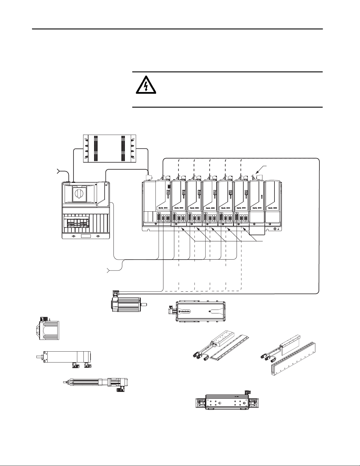
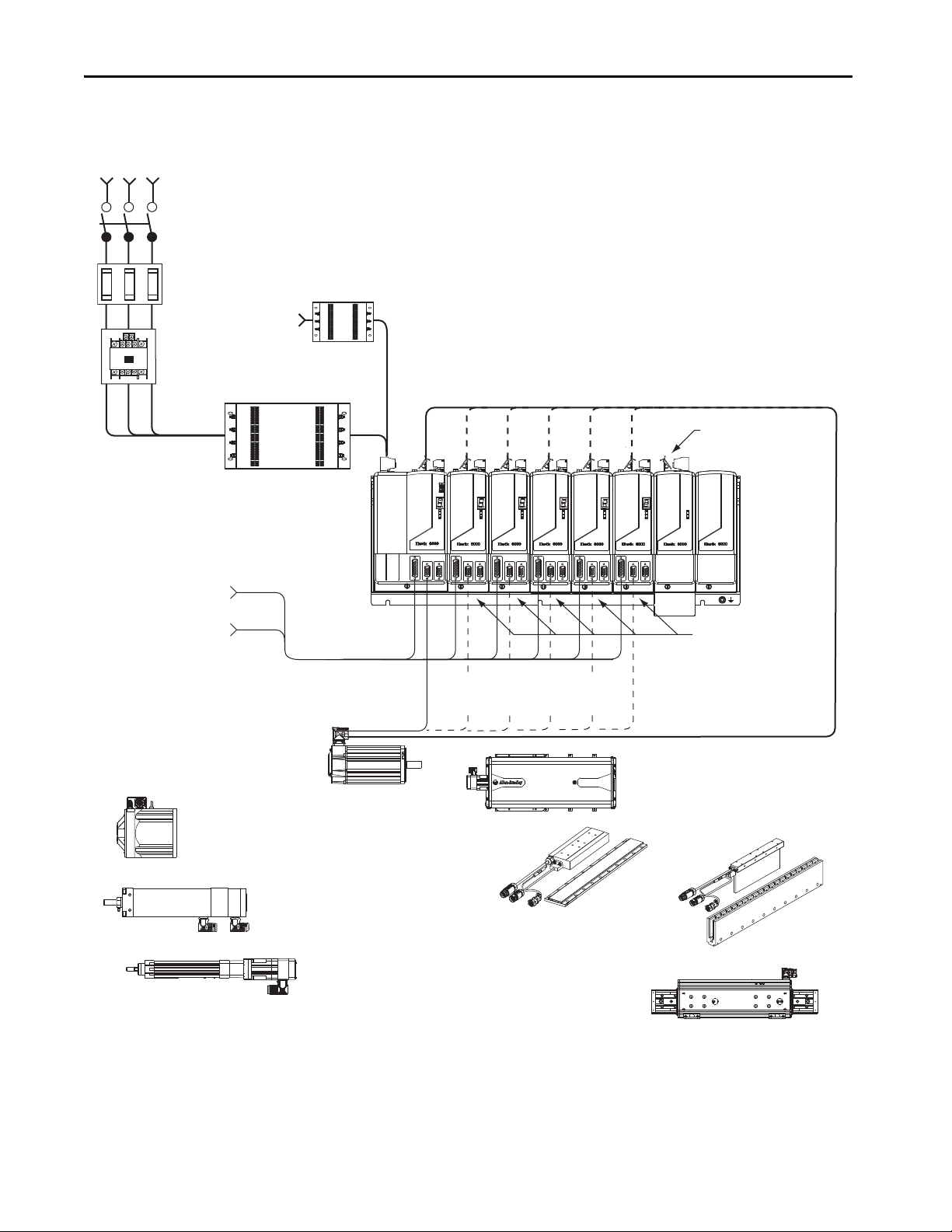
Typical Hardware
Configurations
Typical Kinetix 6000 system installations include three-phase AC
configurations, with and without the line interface module (LIM), and DC
common-bus configurations.
SHOCK HAZARD: To avoid personal injury due to electrical shock, place a
2094-PRF slot-filler module in all empty slots on the power rail. Any power
rail connector without a module installed disables the Bulletin 2094 system;
however, control power is still present.
Figure 1 - Typical Kinetix 6000 System Installation (with LIM)
(1) RDD-Series direct-drive motors require the 2090-K6CK-KENDAT low-profile feedback module.
Rockwell Automation Publication 2094-UM001J-EN-P - March 2017 15
Page 16
Kinetix 6000 Multi-axis Servo Drive System
Line
Disconnect
Device
Magnetic
Contac tor
Input
Fusing
Three-phase
Input Power
Single-phase
Control Power
2094-xCxx-Mxx-S
IAM Module
2094-PRSx
Power Rail
I/O Connections
To I np ut S en sor s
and Control String
2094-xMxx-S
Axis Modules (5)
2094-BSP2
Shunt Module
(optional component)
2094-PRF
Slot-filler Module
(required to fill
any unused slots)
2090-K6CK-Dxxx
Low Profile Connector Kits for
I/O, Motor Feedback, and Aux Feedback
2090-XXLF-xxxx
AC Lin e Filter
(required for CE)
MP-Series and TL-Series Rotary Motors
(MPL-xxxx motors shown)
MP-Series Integrated Linear Stages
(MPAS-B9xxx ballscrew shown)
Bulletin 2090
Motor Feedback Cables
Bulletin 2090
Motor Power Cables
MP-Series Electric Cylinders
(MPAR-Bxxxx electric cylinder shown)
MP-Series Heavy Duty Electric Cylinders
(MPAI-Bxxxx electric cylinders shown)
RDD-Series Direct Drive Motors
(1)
(RDB-Bxxxx motor shown)
LDC-Series Linear Motors
(LDC-Cxxxxxxx linear motor shown)
LDL-Series Linear Motors
(LDL-xxxxxxxx linear motor shown)
2090-XXLF-xxxx
AC Lin e Filter
(required for CE)
LDAT-Series Linear Thrusters
(LDL-Sxxxxxx-xBx linear thrusters only)
Chapter 1 Start
Figure 2 - Typical Kinetix 6000 System Installation (without LIM)
www.ab.com
MADE IN USA
CAT. NO. LDC-M075500
SERIAL NO. XXXX X XXXX
SERIES A
(1) RDD-Series direct-drive motors require the 2090-K6CK-KENDAT low-profile feedback module.
16 Rockwell Automation Publication 2094-UM001J-EN-P - March 2017
Page 17
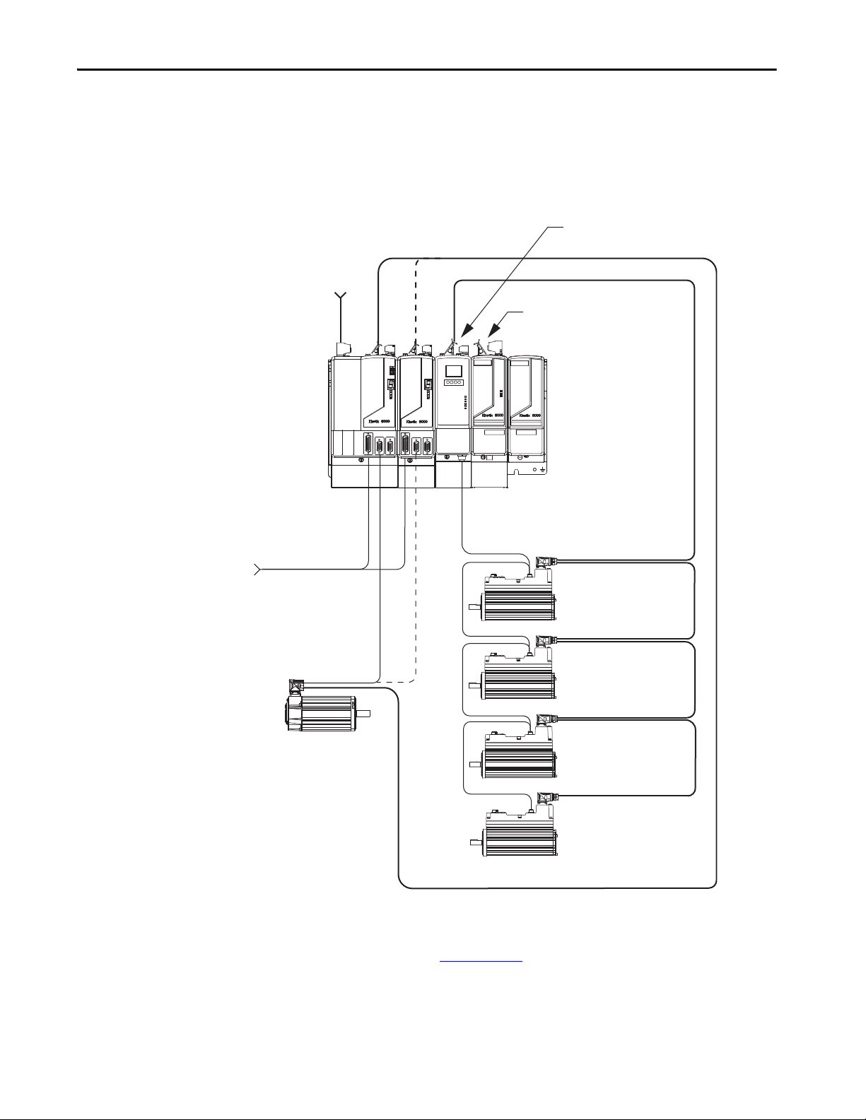
Start Chapter 1
Three-phase
Input Power
Kinetix 6000 Multi-axis
Servo Drive System
2094-BSP2
Shunt Module
(optional component)
2094-SEPM-B24-S
IPIM Module
2094-PRSx
Power Rail
2094-PRF
Slot Filler Module
(required to fill any
unused slots)
To Input Sensors
and Control String
2090-K6CK-Dxxxx
Low Profile Connector Kits for I/O,
Motor Feedback, and Aux Feedback
Compatible Rotary Motors,
Linear Motors, and Linear Actuators
(MPL-Bxxxx motor shown)
Bulletin 2090
Motor Feedback Cables
Bulletin 2090
Motor Power Cables
Bulletin 2090 Hybrid Cables
Bulletin 2090
Network Cables
MDF-SBxxxxx-Qx8xB-S
Drive-Motor Unit
MDF-SBxxxxx-Qx8xB-S
Drive-Motor Unit
MDF-SBxxxxx-Qx8xB-S
Drive-Motor Unit
MDF-SBxxxxx-Qx8xB-S
Drive-Motor Unit
This configuration illustrates the Kinetix 6000M integrated drive-motor
(IDM) system with IDM power interface module (IPIM) installed on the
Bulletin 2094 power rail. The IPIM module is included in the drive-to-drive
fiber-optic cable installation along with the axis modules.
Figure 3 - Typical Kinetix 6000M Integrated Drive-Motor System Installation
For more information on Kinetix 6000M integrated drive-motor system
installation, refer to the Kinetix 6000M Integrated Drive-Motor System User
Manual, publication 2094-UM003
.
Rockwell Automation Publication 2094-UM001J-EN-P - March 2017 17
Page 18
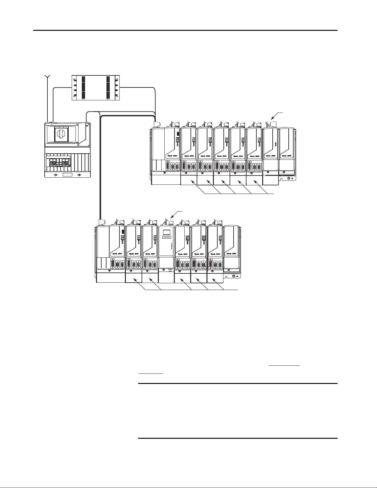
Chapter 1 Start
Kinetix 6000 Multi-axis Servo Drive System
Three- phase
Input Power
115/230V Control Power
2094-BCxx-Mxx-S
IAM Module
Common Bus Leader
2094-PRSx
Power Rail
2094-BMxx-S
Axis Modules (5)
2094-BSP2
Shunt Module
(optional component)
2094-PRF
Slot-filler Module
(required to fill
any unused slots)
2094-BCxx-Mxx-S
IAM Module
Common Bus Follower
2094-PRSx
Power Rail
2094-BMxx-S
Axis Modules (5)
2094-PRF
Slot-filler Module
(required to fill
any unused slots)
2094-BLxxS
Line Interface Module
(optional component)
DC Common Bus
2090-XXLF-xxxx
AC Lin e Filter
(required for CE)
2094-SEPM-B24-S
IPIM Module
Figure 4 - Typical (400V-class) DC Common Bus System Installation
In the example above, the leader IAM module is connected to the follower
IAM module via the DC common-bus. The follower system also includes the
Kinetix 6000M integrated drive-motor (IDM) power interface module
(IPIM) that supports up to 16 IDM units.
When planning your panel layout, you must calculate the total bus capacitance
of your DC common-bus system to be sure that the leader IAM module is sized
sufficiently to precharge the entire system. Refer to Appendix
page 227,
for more information.
IMPORTANT If total bus capacitance of your system exceeds the leader IAM module
precharge rating and input power is applied, the IAM module sevensegment status indicator displays error code E90 (precharge timeout fault).
C, beginning on
To correct this condition, you must replace the leader IAM module with a
larger module or decrease the total bus capacitance by removing the IPIM
module or AM modules.
18 Rockwell Automation Publication 2094-UM001J-EN-P - March 2017
Page 19
Start Chapter 1
SERCOS interface
Tx (rear)
Rx (front)
OK
CP
0.2 m
(7.1 in.)
0.1 m
(5.1 in.)
0.1 m
(5.1 in.)
62006200
SAFE SPEED
62006200
SAFE SPEED
0.1 m
(5.1 in.)
0.2 m
(7.1 in.)
TX
RX
TX
RX
Logix5000 Sercos interface Module
Logix5000 Controller
(ControlLogix controller is shown)
The Logix Designer
Application
2090-SCxxx-x
Sercos Fiber-optic Cable
Logix5000 Controller Programming Network
2094-xMxx-S
Axis Modules (5)
2094-xCxx-Mxx-S
IAM Module
0.1 m (5.1 in.)
Kinetix 6000 Drive-to-Drive Sercos Cables
Kinetix 6000 Single-wide
2094-BCxx-Mxx-S
IAM Module
Kinetix 6000 Double-wide
2094-BCxx-Mxx-S
IAM Module
2094-BMxx-S Single-wide AM Module
2094-BMxx-S Double-wide AM Module
2094-BMxx-M Single-wide AM Power Modules
with 2094-SE02F-M00-Sx Control Modules
2094-SEPM-B24-S IPIM Module
2094-BMxx-S Single-wide AM Module
Kinetix 6200 (top view)
Sercos Connectors
Kinetix 6000 and
Kinetix 6000M (top view)
Sercos Connectors
2094-PRSx
Power Rail
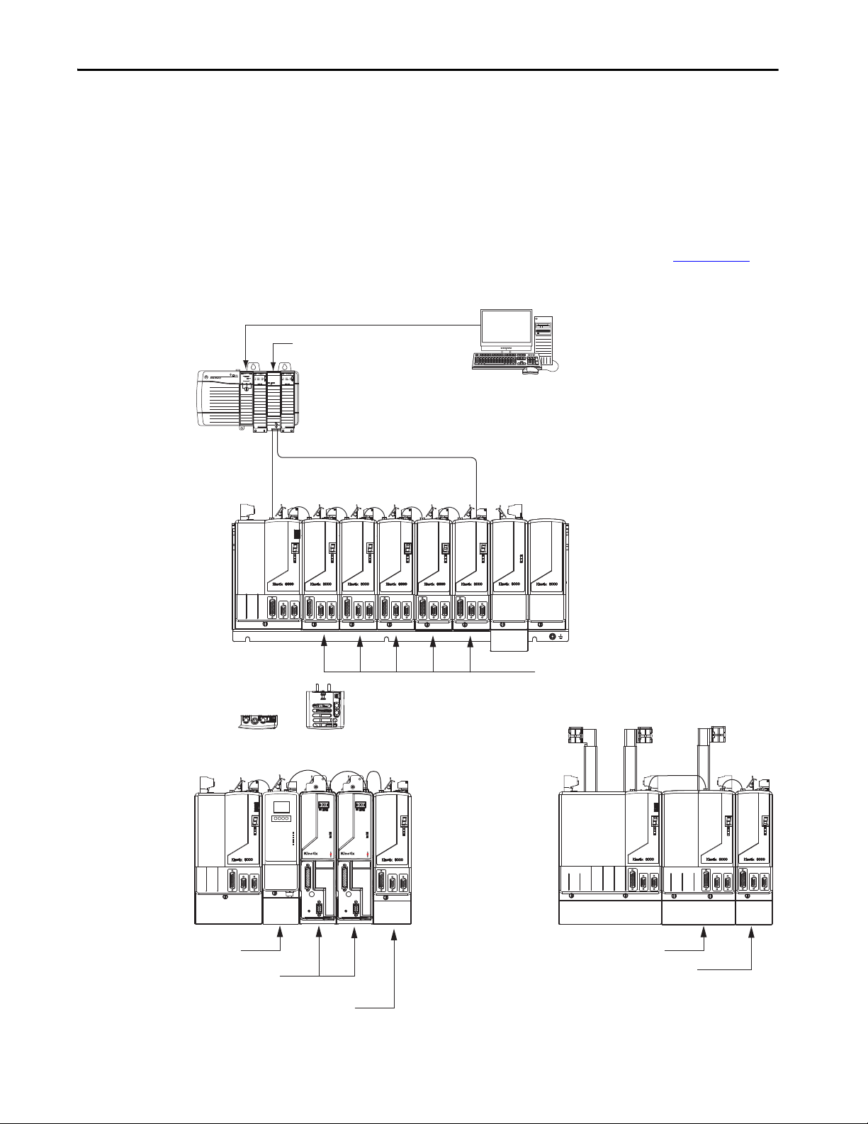
Typical Communication
Configurations
In this example, drive-to-drive Sercos cables and catalog numbers are shown
when Kinetix 6000, Kinetix 6000M, and Kinetix 6200 drive modules exist on
the same power rail.
The Kinetix 6200 control modules use Sercos interface for configuring the
Logix5000 module and the EtherNet/IP network for diagnostics and
configuring safety functions. An Ethernet cable is connected to each control
module during safety configuration. For more information on Ethernet cables,
refer to the Industrial Ethernet Media Brochure, publication 1585-BR001
Figure 5 - Typical Kinetix 6000 and Kinetix 6200 Communication (Sercos)
.
Rockwell Automation Publication 2094-UM001J-EN-P - March 2017 19
Page 20

Chapter 1 Start
Catalog Number Explanation
Integrated Axis Modules (230V)
Kinetix 6000, IAM, 200V-class, 3 kW converter, 5 A inverter 2094-AC05-MP5-S 2094-AC05-MP5
Kinetix 6000, IAM, 200V-class, 3 kW converter, 9 A inverter 2094-AC05-M01-S 2094-AC05-M01
Kinetix 6000, IAM, 200V-class, 6 kW converter, 15 A inverter 2094-AC09-M02-S 2094-AC09-M02
Kinetix 6000, IAM, 200V-class, 11 kW converter, 24 A inverter 2094-AC16-M03-S 2094-AC16-M03
Kinetix 6000, IAM, 200V-class, 23 kW converter, 49 A inverter 2094-AC32-M05-S 2094-AC32-M05
Integrated Axis Modules (460V)
Kinetix 6000, IAM, 400V-class, 6 kW converter, 4 A inverter 2094-BC01-MP5-S
Kinetix 6000, IAM, 400V-class, 6 kW converter, 9 A inverter 2094-BC01-M01-S
Kinetix 6000, IAM, 400V-class, 15 kW converter, 15 A inverter 2094-BC02-M02-S
Kinetix 6000, IAM, 400V-class, 28 kW converter, 30 A inverter 2094-BC04-M03-S
Kinetix 6000, IAM, 400V-class, 45 kW converter, 49 A inverter 2094-BC07-M05-S
Axis Modules (230V)
Kinetix 6000, AM, 200V-class, 5 A 2094-AMP5-S 2094-AMP5
Kinetix 6000, AM, 200V-class, 9 A 2094-AM01-S 2094-AM01
Kinetix 6000, AM, 200V-class, 15 A 2094-AM02-S 2094-AM02
Kinetix 6000, AM, 200V-class, 24 A 2094-AM03-S 2094-AM03
Kinetix 6000, AM, 200V-class, 49 A 2094-AM05-S 2094-AM05
Axis Modules (460V)
Kinetix 6000, AM, 400V-class, 4 A 2094-BMP5-S
Kinetix 6000, AM, 400V-class, 9 A 2094-BM01-S
Kinetix 6000, AM, 400V-class, 15 A 2094-BM02-S
Kinetix 6000, AM, 400V-class, 30 A 2094-BM03-S
Kinetix 6000, AM, 400V-class, 49 A 2094-BM05-S
(1) You can configure the peak inverter current rating of this 460V (series B and C) IAM or AM module for 250% of continuous inverter current.
(2) You can configure the peak inverter current rating of this 460V (series B and C) IAM or AM module for 200% of continuous inverter current. Refer to Peak Enhancement
Specifications on page 74, for more information on drive performance in the peak-enhanced mode.
Kinetix 6000 (Bulletin 2094) drive catalog numbers and descriptions are listed
in the tables below.
IMPORTANT Throughout this publication, when the IAM or AM module catalog number
is followed by -x, for example 2094-BMP5-x, the variable (x) indicates that
the drive module may or may not include the safe torque-off feature.
Table 3 - Kinetix 6000 Drive Catalog Numbers
Cat. No.
(with safe torque-off feature)
(1)
(1)
(1)
(1)
(2)
(1)
(1)
(1)
(1)
(2)
Cat. No.
(without safe torque- off feature)
2094-BC01-MP5
2094-BC01-M01
2094-BC02-M02
2094-BC04-M03
2094-BC07-M05
2094-BMP5
2094-BM01
2094-BM02
2094-BM03
2094-BM05
Table 4 - Kinetix 6000 Drive Component Catalog Numbers
Drive Components Cat. No.
Integrated power interface (IPIM) module, 400V-class, 15 kW, 24 A (rms) 2094-SEPM-B24-S
Kinetix 6000 shunt module, 200/400V-class, 200 W 2094-BSP2
Kinetix 6000 slot-filler module, 200/400V-class 2094-PRF
20 Rockwell Automation Publication 2094-UM001J-EN-P - March 2017
Page 21

Start Chapter 1
Kinetix Drive Component
Compatibility
IAM Module Control Module
2094-BCxx-Mxx-S
(series B and C)
2094-BCxx-Mxx-M
(IAM power module)
N/A
2094-SE02F-M00-Sx
Sercos interface
2094-EN02D-M01-Sx
EtherNet/IP network
The 2094-BCxx-Mxx-M and 2094-BMxx-M power modules contain the same
power structure as the 2094-BCxx-Mxx-S and 2094-BMxx-S drive modules.
Because of this, the 2094-BSP2 shunt module, 2094-PRF slot-filler module,
and 2094-PRSx power rails are supported by both drive families.
In addition, 2094-BMxx-M AM power modules with Sercos interface are
supported on power rails with a 2094-BCxx-Mxx-S IAM drive module.
Conversely, 2094-BMxx-S AM drive modules are supported on power rails
with a 2094-BCxx-Mxx-M IAM power module with Sercos interface.
IMPORTANT Kinetix 6500 EtherNet/IP control modules (catalog numbers
2094-EN02D-M01-Sx) are not compatible with IAM/AM modules on the
same Bulletin 2094 power rail with Kinetix 6000 or Kinetix 6200 Sercos
drives.
Table 5 - IAM and AM Module/Network Compatibility
2094-BMxx-M
2094-BMxx-S
Kinetix 6000 AM Module
Fully compatible Fully compatible Not compatible
Not compatible Not compatible Fully compatible
2094-SE02F-M00-Sx
Kinetix 6200 Control Module
AM Power Modules
2094-EN02D-M01-Sx
Kinetix 6500 Control Module
Kinetix 6000M Integrated
Drive-Motor System
Compatibility
For additional information on the 2094-BCxx-Mxx-M (IAM) and
2094-BMxx-M (AM) modules, refer to the Kinetix 6200 and Kinetix 6500
Multi-axis Servo Drives User Manual, publication 2094-UM002
.
Bulletin 2094 power rails with Kinetix 6000 (series B and C) or Kinetix 6200
drives are compatible with Kinetix 6000M integrated drive-motor (IDM)
systems. The IDM power interface module (IPIM) mounts to the power rail
and connects to as many as 16 IDM units.
Table 6 - IPIM Module Compatibility
IAM Module Control Module
2094-BCxx-Mxx-S
(series B and C)
2094-BCxx-Mxx-M
(IAM power module)
N/A
2094-SE02F-M00-Sx Sercos interface
2094-EN02D-M01-Sx EtherNet/IP network Not compatible
2094-SEPM-B24-S
IDM Power Interface Module (IPIM)
Fully compatible
For more information on Kinetix 6000M integrated drive-motor system
installation, refer to the Kinetix 6000M Integrated Drive-Motor System User
Manual, publication 2094-UM003
.
Rockwell Automation Publication 2094-UM001J-EN-P - March 2017 21
Page 22

Chapter 1 Start
Agency Compliance
If this product is installed within the European Union and has the CE mark,
the following regulations apply.
ATT EN TI ON : Meeting CE requires a grounded system, and the method of
grounding the AC line filter and drive must match. Failure to do this renders
the filter ineffective and can cause damage to the filter. For grounding
examples, refer to Grounded Power Configurations on page 85
For more information on electrical noise reduction, refer to the System Design
for Control of Electrical Noise Reference Manual, publication GMC-RM001
.
CE Requirements (system without LIM module)
To meet CE requirements when your Kinetix 6000 system does not include the
LIM module, these requirements apply.
• Install 2090-XXLF-xxxx AC line filters for three-phase input power and
single-phase control power (for example, Schaffner P/N FN 355-10-05
or Roxburgh P/N RES5F08) as close to the IAM module as possible.
• Use 2090 series motor power cables or use connector kits and terminate
the cable shields to the chassis clamp provided.
• Combined motor power cable lengths for all Kinetix 6000 axes and
hybrid cable lengths for all IDM units on the same DC bus must not
exceed 240 m (787 ft) with 400V-class systems or 160 m (525 ft) with
200V-class systems. Drive-to-motor power cables must not exceed 90 m
(295.5 ft).
• Use 2090 series motor feedback cables or use connector kits and
properly terminate the feedback cable shield. Drive-to-motor feedback
cables must not exceed 90 m (295.5 ft).
• Install the Kinetix 6000 system inside an enclosure. Run input power
wiring in conduit (grounded to the enclosure) outside of the enclosure.
Separate signal and power cables.
.
Refer to Appendix A on page 187
power wiring and drive/motor interconnect diagrams.
22 Rockwell Automation Publication 2094-UM001J-EN-P - March 2017
for interconnect diagrams, including input
Page 23

Start Chapter 1
CE Requirements (system with LIM module)
To meet CE requirements when your Kinetix 6000 system includes the LIM
module, follow all the requirements as stated in CE Requirements (system
without LIM module) and these additional requirements as they apply to the
AC line filter.
• Install the LIM module (catalog numbers 2094-AL09 or 2094-BL02) as
close to the IAM module as possible.
• Install the LIM module (catalog numbers 2094-ALxxS, 2094-BLxxS, or
2094-XL75S-Cx) with line filter (catalog number 2090-XXLF-xxxx) as
close to the IAM module as possible.
When the LIM module (catalog numbers 2094-ALxxS, 2094-BLxxS, or
2094-XL75S-Cx) supports two IAM modules, each IAM module
requires an AC line filter installed as close to the IAM module as
possible.
Rockwell Automation Publication 2094-UM001J-EN-P - March 2017 23
Page 24

Chapter 1 Start
Notes:
24 Rockwell Automation Publication 2094-UM001J-EN-P - March 2017
Page 25
Chapter 2
Plan the Kinetix 6000 Drive System Installation
This chapter describes system installation guidelines used in preparation for
mounting your Kinetix® 6000 drive components.
Top ic Pa ge
System Design Guidelines 26
Electrical Noise Reduction 34
ATT EN TI ON : Plan the installation of your system so that you can perform all
cutting, drilling, tapping, and welding with the system removed from the
enclosure. Because the system is of the open type construction, be careful to
keep any metal debris from falling into it. Metal debris or other foreign
matter can become lodged in the circuitry, which can result in damage to
components.
Rockwell Automation Publication 2094-UM001J-EN-P - March 2017 25
Page 26

Chapter 2 Plan the Kinetix 6000 Drive System Installation
System Design Guidelines
Use the information in this section when designing your enclosure and
planning to mount your system components on the panel.
For on-line product selection and system configuration tools, including
AutoCAD (DXF) drawings of the product, refer to
http://www.rockwellautomation.com/en/e-tools
.
System Mounting Requirements
• To comply with UL and CE requirements, the Kinetix 6000 drive
system must be enclosed in a grounded conductive enclosure offering
protection as defined in standard EN 60529 (IEC 529) to IP54 such
that they are not accessible to an operator or unskilled person. A NEMA
4X enclosure exceeds these requirements providing protection to IP66.
• The panel you install inside the enclosure for mounting your system
components must be on a flat, rigid, vertical surface that won’t be
subjected to shock, vibration, moisture, oil mist, dust, or corrosive
vapors.
• Size the drive enclosure so as not to exceed the maximum ambient
temperature rating. Consider heat dissipation specifications for all drive
components.
• Combined motor power cable lengths for all axes and hybrid cable
lengths for all IDM units on the same DC bus must not exceed 240 m
(787 ft) with 400V-class systems or 160 m (525 ft) with 200V-class
systems. Drive-to-motor power cables must not exceed 90 m (295.5 ft).
IMPORTANT System performance was tested at these cable length specifications.
These limitations also apply when meeting CE requirements.
• Segregate input power wiring and motor power cables from control
wiring and motor feedback cables. Use shielded cable for power wiring
and provide a grounded 360° clamp termination.
• Use high-frequency (HF) bonding techniques to connect the modules,
enclosure, machine frame, and motor housing, and to provide a lowimpedance return path for high-frequency (HF) energy and reduce
electrical noise.
Refer to the System Design for Control of Electrical Noise Reference Manual,
publication GMC-RM001
reduction.
, to better understand the concept of electrical noise
26 Rockwell Automation Publication 2094-UM001J-EN-P - March 2017
Page 27

Plan the Kinetix 6000 Drive System Installation Chapter 2
Transformer Selection
The IAM module does not require an isolation transformer for three-phase
input power. However, a transformer can be required to match the voltage
requirements of the controller to the available service.
To size a transformer for the main AC power inputs, refer to the
Kinetix 6000 power specifications in the Kinetix Servo Drives Technical Data,
publication KNX-TD003
IMPORTANT If using an autotransformer, make sure that the phase to neutral/ground
voltages do not exceed the input voltage ratings of the drive.
IMPORTANT Use a form factor of 1.5 for three-phase power (where form factor is used to
compensate for transformer, drive module, and motor losses, and to account
for utilization in the intermittent operating area of the torque speed curve).
For example, to size a transformer to the voltage requirements of a
2094-BC01-M01-S integrated axis module:
2094-BC01-M01-S = 6 kW continuous x 1.5 = 9.0 KVA transformer
.
AC Line Filter Selection
These AC line filters are available for your servo drive input power.
Table 7 - Kinetix 6000 (three-phase) AC Line Filter Selection
Drive
Cat. No.
2094-AC05-MP5-S
2094-AC09-M02-S
2094-AC16-M03-S 75 5.2 (11.4) 2090-XXLF-375
2094-AC32-M05-S 100 9.5 (20.9) 2090-XXLF-3100
2094-BC01-MP5-S
2094-BC02-M02-S
2094-BC04-M03-S 75 5.2 (11.4) 2090-XXLF-375B
2094-BC07-M05-S 100 9.5 (20.9) 2090-XXLF-3100
Volt age
500V AC
50/60 Hz
500V AC
50/60 Hz
Current
A @ 50 °C (122 °F)
30 2.7 (5.9) 2090-XXLF-X330B2094-AC05-M01-S
30 2.7 (5.9) 2090-XXLF-X330B2094-BC01-M01-S
Refer to the Kinetix Motion Accessories Specifications Technical Data,
publication KNX-TD004
, for additional AC line filter specifications.
Weight, a pprox
kg (lb)
AC Line Filter
Cat. No.
Rockwell Automation Publication 2094-UM001J-EN-P - March 2017 27
Page 28

Chapter 2 Plan the Kinetix 6000 Drive System Installation
Circuit Breaker/Fuse Options
The 2094-xCxx-Mxx-S and 2094-xMxx-S drive modules, and the
Kinetix 6000M integrated drive-motor system (2094-SEPM-B24-S IPIM
module and MDF-SBxxxxx IDM units) use internal solid-state motor shortcircuit protection and, when protected by suitable branch circuit protection,
are rated for use on a circuit capable of delivering up to 200,000 A (fuses) and
65,000 A (circuit breakers).
Table 8 - Control and DC-bus Circuit Protection Specifications
IAM Module
Cat. No.
2094-AC05-MP5-S
2094-AC05-M01-S
2094-AC09-M02-S FWH-35B A50P35-4
2094-AC16-M03-S
2094-AC32-M05-S FWH-125B A50P125-4
2094-BC01-MP5-S
2094-BC01-M01-S
2094-BC02-M02-S FWJ-40A A70QS40-4 HSJ40
2094-BC04-M03-S FWJ-70A A70QS70-4 HSJ70
2094-BC07-M05-S FWJ-125A A70QS125-4 HSJ125
(1) Use FNQ-R-7.5 circuit breaker for higher single -cycle inrush current capability. This is recommended when the continuous control-power current exceeds 3.0 A.
(2) Use 1492-SPM1D150 circuit breaker for higher single -cycle inrush current capability. This is recommended when the continuous control-power current exceeds 3.0 A.
(3) Mersen fuses were formerly known as Ferraz Shawmut.
Bussmann Fuse
FNQ-R-10 (10 A)
FNQ-R-10 (10 A) or
FNQ-R-7.5 (7.5 A)
Control Input Power DC-bus Power
Allen-Bradley® Circuit Breaker
(1)
(non-UL)
1492-SPM2D060
1492-SPM2D200
1492-SPM2D060 or
1492-SPM1D150
(2)
Bussmann Fuse Mersen Fuse
N/A A50P20-1
FWH-60B A50P60-4
FWJ-20A14F DCT20-2 HSJ20
Input Power Circuit Protection (LIM)
The 2094-AL09 and 2094-BL02 line interface modules (LIM) contain
supplementary protection devices and, when protected by suitable branch
circuit protection, are rated for use on a circuit capable of delivering up to 5000
A. When these modules are used, protection on the line side of the LIM
module is required. Fuses must be class J or CC only.
(3)
The 2094-ALxxS, 2094-BLxxS, and 2094-XL75S-Cx LIM modules contain
branch circuit rated devices suitable for use on a circuit capable of delivering up
to 65,000 A (400V-class) or 100,000 A (200V-class).
Refer to the Line Interface Module Installation Instructions, publication
2094-IN005
, for power specifications and more information on using the LIM
module.
Refer to Input Power Circuit Protection (without LIM) on page 29
drive system does not include the LIM module.
28 Rockwell Automation Publication 2094-UM001J-EN-P - March 2017
when your
Page 29

Plan the Kinetix 6000 Drive System Installation Chapter 2
Molded Case CB
Cat. No.
Motor Protection CB
Cat. No.
Miniature CB
Cat. No.
Molded Case CB
Cat. No.
140M-F8E-C16
1492-SPM3D300 1489-M3D300
NA2094-AC05-M01-S 230V
140G-G6C3-C50
NA2094-BC01-M01-S 360…480V
140G-G6C3-C50
140M-F8E-C32
N/A N/A NA
NA
140G-G6C3-C50
140G-G6C3-C90 140G-G6C3-C90
1492-SPM3D300 1489-M3D300
NA
140G-G6C3-C50
N/A N/A NA
140G-G6C3-C90 140G-G6C3-C90
Input Power Circuit Protection (without LIM)
The fuses and Allen-Bradley circuit breakers shown in Ta b l e 9 are recommended for use with 2094-xCxx-Mxx-S IAM
modules when the line interface module (LIM) is not used.
140M-F8E-C16
Motor Protection CB,
Self-protected CMC
Miniature CB
Cat. No.
Cat. No.
module. Follow all applicable NEC and local codes.
IMPORTANT LIM Modules (catalog numbers 2094-ALxxS, 2094-BLxxS, and 2094-XL75S-Cx) provide branch circuit protection to the IAM
140M-F8E-C16 140M-F8E-C16
1489-M3D300
1489-M3D400 140M-F8E-C20 1492-SPM3D400 1489-M3D400 140M- F8E-C20
N/A NA
Table 9 - Input Power Circuit Protection Specifications
KTK-R-20 (20 A)
Class CC
KTK-R-30 (30 A)
Class CC
LPJ-45SP (45 A)
Fuses (Bussmann)
Cat. No.
KTK-R-20 (20 A)
Class CC
Drive Voltage
(three-phase)
nom
Class J
LPJ-80SP (80 A)
Class J
140M-F8E-C32
KTK-R-20 (20 A)
Class CC
1489-M3D300
KTK-R-20 (20 A)
140M-F8E-C32 140M-F8E-C32
Class CC
1489-M3D400 140M-F8E-C45 1492-SPM3D400 1489-M3D400 140M-F8E-C45
KTK-R-30 (30 A)
Class CC
N/A NA
IAM module.
Refer to the Kinetix Servo Drives Technical Data, publication KNX-TD003, for additional power specifications for your
LPJ-45SP (45 A)
Class J
LPJ-80SP (80 A)
Class J
Kinetix 6000 Drives UL Applications IEC (non-UL) Applications
IAM Module
2094-AC09-M02-S 230V
Cat. No.
2094-AC05-MP5-S 230V
2094-AC16-M03-S 230V
2094-AC32-M05-S 230V
2094-BC01-MP5-S 360…480V
2094-BC02-M02-S 360…480V
2094-BC04-M03-S 360…480V
2094-BC07-M05-S 360…480V
Rockwell Automation Publication 2094-UM001J-EN-P - March 2017 29
Page 30

Chapter 2 Plan the Kinetix 6000 Drive System Installation
Enclosure Selection
This example is provided to assist you in sizing an enclosure for your Bulletin
2094 drive system. The example system consists of these components:
• 6-axis Bulletin 2094 servo drive system
• Line Interface Module (LIM)
• ControlLogix® chassis and modules (controller)
Size the Bulletin 2094 servo drive and LIM module and use the results to
predict the amount of heat dissipated into the enclosure. You also need heat
dissipation data from other equipment inside the enclosure (such as the
ControlLogix controller). Once the total amount of heat dissipation (in watts)
is known, you can calculate the minimum enclosure size.
Table 10 - Bulletin 2094 System Heat Dissipation Example
Enclosure Component Description Loading
2094-BC02-M02-x
2094-BM02-x Axis module (AM), 400/460V, 15 A 60% 93
2094-BM02-x Axis module (AM), 400/460V, 15 A 60% 93
2094-BM01-x Axis module (AM), 400/460V, 9 A 40% 73
2094-BM01-x Axis module (AM), 400/460V, 9 A 40% 73
2094-BM01-x Axis module (AM), 400/460V, 9 A 20% 57
2094-BL25S Line interface module (LIM), 400/460V, 25 A; 24V DC 20 A 100% 43
2094-PRS6 Power rail, 460V, 6 axis N/A 0
2090-XB33-32 Resistive brake module (RBM), 33 A, 32 Ω N/A 30
Total Kinetix 6000 system wattage 578
(1) To determine heat dissipation specifications for your drive system components, refer to Tabl e 12 on page 32.
Integrated axis module (IAM),
400/460V
15 kW (converter section) 20% 44
15 A (inverter sect ion) 40% 72
(1)
Heat Dissipation
watts
(1)
30 Rockwell Automation Publication 2094-UM001J-EN-P - March 2017
Page 31

Plan the Kinetix 6000 Drive System Installation Chapter 2
75
60
45
30
15
0
0 20 40 6 0 8 0 100
Backplane
Power Load
(watts)
Real Power (watts)
1756-P B72
1756-P B75
DC
A =
4.08Q
T - 1.1
A =
0.38 (612)
1.8 (20) - 1.1
= 6.66 m
2
Table 11 - ControlLogix System Heat Dissipation Example
Enclosure
Component
Description
Backplane Power Load
watts
1756-M08SE 8-axis Sercos interface module 3.2 0
1756-L5563 L63 ControlLogix processor 4.5 0
1756-IB16D 16 -point input module 0.84 5.8
1756-OB16D 16 -point output module 4.64 3.3
1756-ENxTx EtherNet/IP communication module 4.0 0
Backplane total 17.18
(2)
1756-PB72 24V DC ControlLogix power supply N/A 25
1756-A7 7-slot mounting chassis N/A N/A
Total ControlLogix system wattage 34.1
(1) For ControlLogix module specifications, refer to the ControlLogix Selection Guide, publication 1756-SG001.
(2) Real power heat dissipation is determined by applying the backplane power load (17.18W) to the graph below.
(1)
Figure 6 - ControlLogix Real Power
Heat Dissipation
watts
N/A
(2)
(1)
For backplane power loading requirements of other ControlLogix power
supplies, refer to the ControlLogix Selection Guide, publication 1756-SG001
In this example, the amount of power dissipated inside the cabinet is the sum of
the Bulletin 2094 system value (578 W) and the ControlLogix system value
(34 W) for a total of 612 W.
With no active method of heat dissipation (such as fans or air conditioning)
either of these approximate equations can be used.
Metric Standard English
0.38Q
A =
1.8T - 1.1
Where T is temperature difference between inside air and
outside ambient (°C), Q is heat generated in enclosure
(Watts), and A is enclosure surface area (m2). The exterior
surface of all six sides of an enclosure is calculated as:
Where T is temperature difference between inside air and
outside ambient (°F), Q is heat generated in enclosure
(Watts), and A is enclosure surface area (ft²). The exterior
surface of all six sides of an enclosure is calculated as:
A = 2dw + 2dh + 2wh A = (2dw + 2dh + 2wh) / 144
Where d (depth), w (width), and h (height) are in meters. Where d (depth), w (width), and h (height) are in inches.
Total system watts dissipated (Q) was calculated at 612 W. The maximum
ambient rating of the Bulletin 2094 system is 50 °C (122 °F) and if the
maximum environmental temperature is 30 °C (86 °F), then T=20 in the
equation below.
.
Rockwell Automation Publication 2094-UM001J-EN-P - March 2017 31
Page 32

Chapter 2 Plan the Kinetix 6000 Drive System Installation
In this example, the enclosure must have an exterior surface of 6.66 m2. If any
portion of the enclosure is not able to transfer heat, do not include that portion
in the calculation.
Because the minimum cabinet depth to house the 460V drive (selected for this
example) is 302 mm (11.9 in.), then the cabinet needs to be approximately
2500 mm (high) x 950 mm (wide) x 302 mm (deep).
2 x (0.3 x 0.95) + 2 x (0.3 x 2.5) + 2 x (0.95 x 2.5) = 6.82 m
2
Because this cabinet size is considerably larger than what is necessary to house
the system components, consider some means of cooling in a smaller cabinet to
be more efficient. Contact your cabinet manufacturer for options available to
cool your cabinet.
Table 12 - Power Dissipation Specifications
Usage as % of Rated Power Output
Bulletin 2094 Drive Modules
IAM (converter) module
2094-AC05-MP5-S 8 11 15 19 24
2094-AC05-M01-S 9 12 16 20 25
2094-AC09-M02-S 1420283646
2094-AC16-M03-S 1930435874
2094-AC32-M05-S 41 68 100 136 176
2094-BC01-MP5-S
2094-BC01-M01-S 33
2094-BC02-M02-S 3644546475
2094-BC04-M03-S 50 67 87 110 135
2094-BC07-M05-SS 71 101 137 179 226
IAM (inverter) module or AM module
2094-AC05-MP5-S or 2094-AMP5-S 28 32 37 41 46
2094-AC05-M01-S or 2094-AM01-S 31 38 46 54 62
2094-AC09-M02-S or 2094-AM02-S 34 45 57 70 84
2094-AC16-M03-S or 2094-AM03-S 48 68 91 116 144
2094-AC32-M05-S or 2094-AM05-S 104 156 212 274 342
2094-BC01-MP5-S or 2094-BMP5-S 46 54 61 69 77
2094-BC01-M01-S or 2094-BM01-S 57 73 90 108 126
2094-BC02-M02-S or 2094-BM02-S 53 72 93 116 142
2094-BC04-M03-S or 2094-BM03-S 94 130 169 211 255
2094-BC07-M05-S or 2094-BM05-S 121 183 252 326 407
Shunt module - 2094-BSP2 68 121 174 227 280
IPIM module - 2094-SEPM-B24-S
(1) Power dissipation for the Bulletin 2094 control modules, catalog numbers 2094-SE02F-M00-Sx and 2094-EN02D-M01-Sx, is included in the IAM and AM power module specific ations.
(2) Internal shunt power is not included in the calculations and must be added based on utilization.
(1)
20% 40% 60% 80% 100%
(2)
18 21 25 29
(2)
To calculate power dissipation for IPIM modules on your 2094 power rail, refer to the Kinetix 6000M Integrated Drive-Motor
User Manual, publication 2094-UM003
.
(watts)
34
32 Rockwell Automation Publication 2094-UM001J-EN-P - March 2017
Page 33
Plan the Kinetix 6000 Drive System Installation Chapter 2
F
Clearance right of the
module is not required.
(1)
Clearance above
for airflow and installation.
Clearance left of the
module is not required.
(1)
Kinetix 6000 Drive System
Mounted on 2094 Power Rail
Power Rail
(2094-PRSx is shown)
50.8 (2.0 in.) clearance below
drive for airflow and installation.
Drive Cat. No. Series F
2094-AC05-Mxx-x
2094-AC09-M02-x
A and C
237 mm
(9.3) in.
2094-AMP5-x,
2094-AM01-x,
2094-AM02-x
2094-AC16-M03-x
2094-AC32-M05-x
A and C
420 mm
(16.5) in.
2094-AM03-x,
2094-AM05-x
2094-BC01-Mxx-x
2094-BC02-M02-x
A, B, and C
287 mm
(11.3) in.
2094-BMP5-x,
2094-BM01-x,
2094-BM02-x
2094-SEPM-B24-S
2094-BSP2
A
2094-BC04-M03-x
2094-BM03-x
A, B, and C
374 mm
(14.7) in.
2094-BC07-M05-x
2094-BM05-x
B and C
2094-BC07-M05-x
2094-BM05-x
A and C
436 mm
(17.2) in.
Refer to Power Dissipation Specifications on page 32, and
Kinetix Servo Drives Technical Data, publication KNX-TD003
,
for Kinetix 6000 drive dimensions.
(1) The power rail (slim), catalog number 2094-PRSx, extends left and right of the first and last module 5.0 mm (0.20 in.). The Bulletin
2094-PRx power rail extends approximately 25.4 mm (1.0 in.) left of the IAM module and right of the last module mounted on the rail.
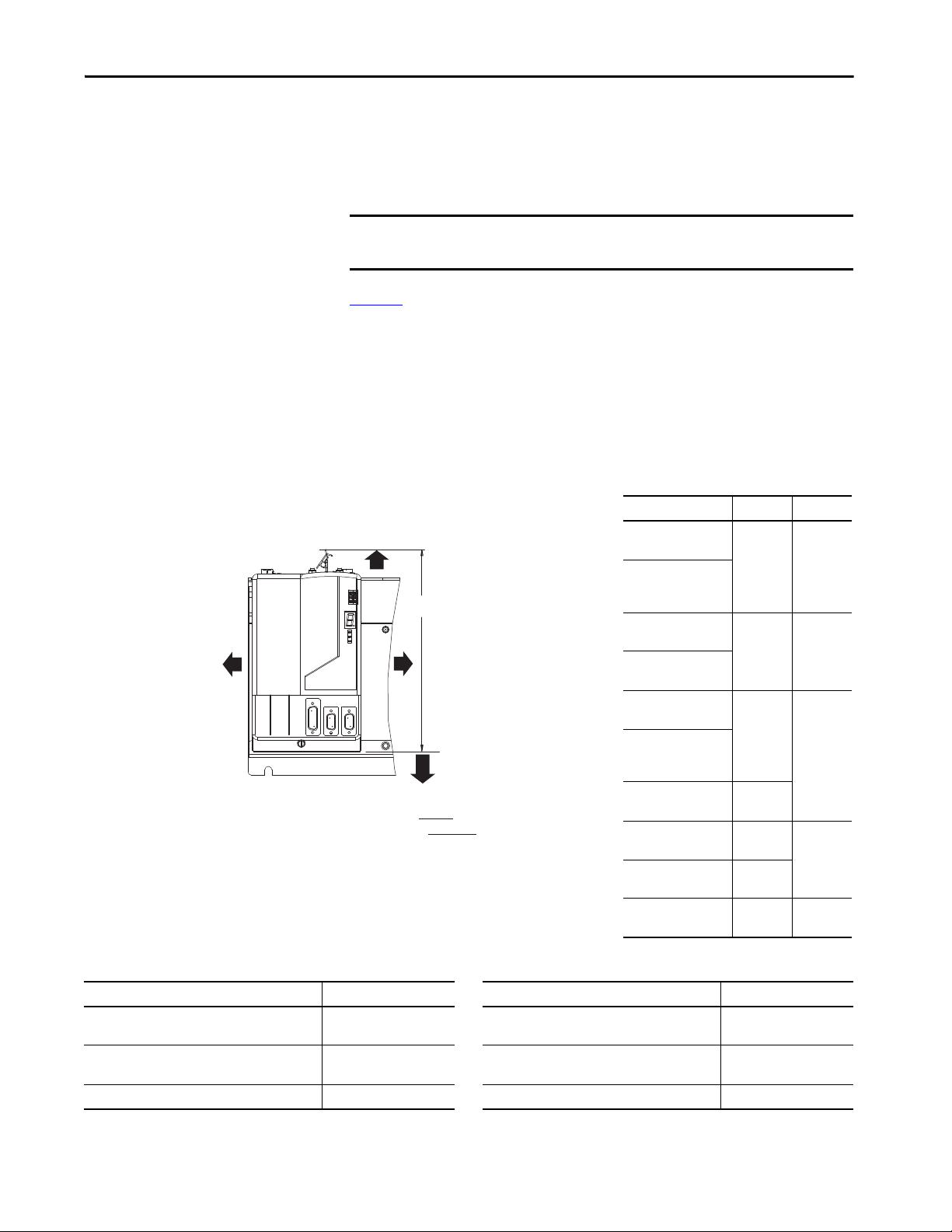
Minimum Clearance Requirements
This section provides information to assist you in sizing your cabinet and
positioning your Bulletin 2094 system components.
IMPORTANT Mount the module in an upright position. Do not mount the module on its
side.
Figure 7
illustrates minimum clearance requirements for proper airflow and
installation:
• Additional clearance is required for the cables and wires connected to
the top and front of the drive.
• Additional clearance left and right of the power rail is required when the
drive is mounted adjacent to noise sensitive equipment or clean
wireways.
Figure 7 - Minimum Clearance Requirements
Drive Cat. No. Cabinet Depth, min
2094-AC05-Mxx-x, 2094-AC09-M02-x, 2094-AMP5-
x, 2094-AM01-x, 2094-AM02-x
2094-BC01-Mxx-x, 2094-BC02-M02-x,
2094-BMP5-x, 2094-BM01-x, 2094-BM02-x
2094-BSP2 272 mm (10.7 in.) 2094-SEPM-B24-S 263 mm (10.3 in.)
(1) Minimum cabinet depth is based on the use of 2090-K6CK-xxxx low-profile connector kits. Other means of making feedback connections can require additional clearance.
Table 13 - Minimum Cabinet Depth
198 mm (7.8 in.)
272 mm (10.7 in.)
Rockwell Automation Publication 2094-UM001J-EN-P - March 2017 33
(1)
Drive Cat. No. Cabinet Depth, min
2094-AC16-M03-x, 2094-AC32-M05-x, 2094-AM03-
x, 2094-AM05-x
2094-BC04-M03-x, 2094-BC07-M05-x,
2094-BM03-x, 2094-BM05-x
198 mm (7.8 in.)
272 mm (10.7 in.)
(1)
Page 34

Chapter 2 Plan the Kinetix 6000 Drive System Installation
Electrical Noise Reduction
This section outlines best practices that minimize the possibility of noiserelated failures as they apply specifically to Kinetix 6000 system installations.
For more information on the concept of high-frequency (HF) bonding, the
ground plane principle, and electrical noise reduction, refer to the System
Design for Control of Electrical Noise Reference Manual, publication
GMC-RM001
.
Bonding Modules
Bonding is the practice of connecting metal chassis, assemblies, frames, shields,
and enclosures to reduce the effects of electromagnetic interference (EMI).
Unless specified, most paints are not conductive and act as insulators. To
achieve a good bond between power rail and the subpanel, surfaces need to be
paint-free or plated. Bonding metal surfaces creates a low-impedance return
path for high-frequency energy.
IMPORTANT To improve the bond between the power rail and subpanel, construct your
subpanel out of zinc plated (paint-free) steel.
Improper bonding of metal surfaces blocks the direct return path and allows
high-frequency energy to travel elsewhere in the cabinet. Excessive highfrequency energy can effect the operation of other microprocessor controlled
equipment.
34 Rockwell Automation Publication 2094-UM001J-EN-P - March 2017
Page 35

Plan the Kinetix 6000 Drive System Installation Chapter 2
Stud-mounting the Subpanel
to the Enclosure Back Wall
Stud-mounting a Ground Bus
or Chassis to the Subpanel
Subpanel Wel ded S tud
Scrape Paint
Flat Washer
If the mounting bracket is coated with
a non-conductive material (anodized
or painted), scrape the material around
the mounting hole.
Star Washer
Nut
Nut
Flat Washer
Mounting Bracket or
Ground Bus
Use a wire brush to remove paint from
threads to maximize ground connection.
Back Wall of
Enclosure
Weld ed St ud
Subpanel
Star Washer
Use plated panels or scrape paint on
front of panel.
Subpanel
Nut
Nut
Star Washer
Flat Washer
Star Washer
Star Washer
Scrape paint on both sides of
panel and use star washers.
Tapped Hole
Bolt
Flat Washer
Ground Bus or
Mounting Bracket
If the mounting bracket is coated with
a non-conductive material (anodized
or painted), scrape the material around
the mounting hole.
Bolt-mounting a Ground Bus or Chassis to the Back-panel
These illustrations show details of recommended bonding practices for painted
panels, enclosures, and mounting brackets.
Figure 8 - Recommended Bonding Practices for Painted Panels
Rockwell Automation Publication 2094-UM001J-EN-P - March 2017 35
Page 36

Chapter 2 Plan the Kinetix 6000 Drive System Installation
Wire B raid
25.4 mm (1.0 in.) by
6.35 mm (0.25 in.)
Paint removed
from cabinet.
Cabinet ground bus
bonded to the subpanel.
Wire B raid
25.4 mm (1.0 in.) by
6.35 mm (0.25 in.)
Bonding Multiple Subpanels
Bonding multiple subpanels creates a common low impedance exit path for the
high frequency energy inside the cabinet. If subpanels are not bonded together,
and do not share a common low impedance path, the difference in impedance
can affect networks and other devices that span multiple panels:
• Bond the top and bottom of each subpanel to the cabinet by using
25.4 mm (1.0 in.) by 6.35 mm (0.25 in.) wire braid. As a rule, the wider
and shorter the braid is, the better the bond.
• Scrape the paint from around each fastener to maximize metal-to-metal
contact.
Figure 9 - Multiple Subpanels and Cabinet Recommendations
36 Rockwell Automation Publication 2094-UM001J-EN-P - March 2017
Page 37

Plan the Kinetix 6000 Drive System Installation Chapter 2
Line Interface Module
Kinetix 6000 System
Dirty Wireway
Clean Wireway
I/O
(1)
and Feedback Cables
Motor Power Cables
Very Dirty Filter/IAM Connections
Segregated (not in wireway)
Route 24V DC I/O
shielded cable.
Route encoder/analog/registration
shielded cables.
Fiber-optic Cable
VAC L oad
VAC L ine
AC Lin e Filter
(required for CE)
No sensitive
(2)
equipment within
150 mm (6.0 in.).
Establishing Noise Zones
Observe these guidelines when the 2094-ALxxS, 2094-BLxxS, or
2094-XL75S-Cx LIM module is used in the Bulletin 2094 system and
mounted left of the IAM module with the AC (EMC) line filter mounted
above the LIM module:
• The clean zone (C) is to the right and beneath the Bulletin 2094 system
(gray wireway).
• The dirty zone (D) is to the left and above the Bulletin 2094 system, and
above and below the LIM module (black wireway).
• The very dirty zone (VD) is from the filter output to IAM module.
Shielded cable is required on the EMC filter (load side) and the braided
shield attached to the clamp provided.
• The Sercos fiber-optic cables are immune to electrical noise, but due to
their delicate nature, route them in the clean zone.
Figure 10 - Noise Zones (LIM mounted left of IAM module)
D
D
D
(1) If drive system I/O cable contains (dirty) relay wires, route cable with LIM module I/O cabl e in dirty wireway.
(2) When space does not permit the 150 mm (6.0 in.) segregation, use a grounded steel shield instead. For examples, refer to the
System Design for Control of Electrical Noise Reference Manual, publication GMC-RM001
VD
VD
D
C
D
D
D
D
C
.
Rockwell Automation Publication 2094-UM001J-EN-P - March 2017 37
Page 38
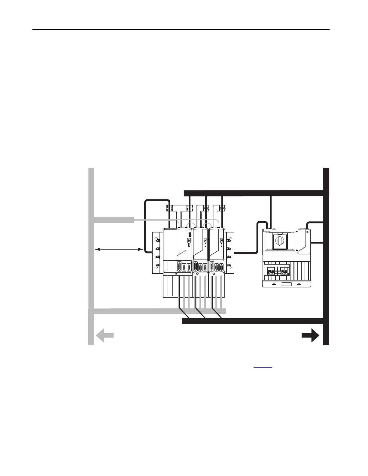
Chapter 2 Plan the Kinetix 6000 Drive System Installation
C
VD
D
D
D
D
VD
D
C
C
D
D
D
I/O
(1)
and Feedback Cables
Line Interface Module
Kinetix 6000
System
Clean Wireway
Dirty Wireway
Motor Power Cables
VAC L oad
VAC L ine
AC (EM C)
Line Filter
Control VAC,
AUX VAC O utput,
and 24V DC Brake
I/O
Very Dirty Filter/IAM Connections
Segregated (not in wireway)
Route 24V DC I/O
shielded cable.
Route encoder/analog/registration
shielded cables.
Fiber-optic Cable
No sensitive
(2)
equipment within
150 mm (6.0 in.).
Observe these guidelines when the 2094-ALxxS, 2094-BLxxS, or
2094-XL75S-Cx LIM module is used in the Bulletin 2094 system and
mounted right of the IAM module with the AC (EMC) line filter mounted
behind the IAM module:
• The clean zone (C) is to the left and beneath the Bulletin 2094 system
(gray wireway).
• The dirty zone (D) is to the right and above the Bulletin 2094 system,
and above and below the LIM module (black wireway).
• The very dirty zone (VD) is from the filter output to IAM module.
Shielded cable is required on the EMC filter (load side) and the braided
shield attached to the clamp provided.
• The Sercos fiber-optic cables are immune to electrical noise, but due to
their delicate nature, route them in the clean zone.
Figure 11 - Noise Zones (LIM with EMC filter behind IAM module)
38 Rockwell Automation Publication 2094-UM001J-EN-P - March 2017
(1) If drive system I/O cable contains (dirty) relay wires, route cable with LIM module I/O cabl e in dirty wireway.
(2) When space does not permit the 150 mm (6.0 in.) segregation, use a grounded steel shield instead. For examples, refer to the
System Design for Control of Electrical Noise Reference Manual, publication GMC-RM001
.
Page 39

Plan the Kinetix 6000 Drive System Installation Chapter 2
C
D
D
D
VD
C
VD
D
D
D
LIM
PRS
PR
I/O
(1)
and Feedback Cables
Line Interface Module
(2094-ALxxS shown)
Kinetix 6000
System
Clean Wireway
Dirty Wireway
Motor Power Cables
VAC L oad
VAC L ine
AC (EMC)
Line Filter
Control VAC,
Auxiliary VAC,
and 24V DC Brake
LIM
I/O
Very Dirty Filter/IAM Connections
Segregated (not in wireway)
Route 24V DC I/O
shielded cable.
Route encoder/analog/registration
shielded cables.
Fiber-optic Cable
2094 Mounting
(3)
Brackets x2
No sensitive
(2)
equipment within
150 mm (6.0 in.).
Observe these guidelines when the 2094-ALxxS, 2094-BLxxS, or
2094-XL75S-Cx LIM module is used in the Bulletin 2094 system and
mounted right of the drive with the AC (EMC) line filter mounted behind the
LIM module:
• The clean zone (C) is to the left and beneath the Bulletin 2094 system
(gray wireway).
• The dirty zone (D) is to the right and above the Bulletin 2094 system,
and above and below the LIM module (black wireway).
• The very dirty zone (VD) is from the filter output to drive. Shielded
cable is required on the EMC filter (load side) and the braided shield
attached to the clamp (when provided).
• The Sercos fiber-optic cables are immune to electrical noise, but due to
their delicate nature, route them in the clean zone.
Figure 12 - Noise Zones (EMC filter behind LIM module)
(1) If drive system I/O cable contains (dirty) relay wires, route cable with LIM module I/O cabl e in dirty wireway.
(2) When space does not permit the 150 mm (6.0 in.) segregation, use a grounded steel shield instead. For examples, refer to the
System Design for Control of Electrical Noise Reference Manual, publication GMC-RM001
(3) Only the 2094-ALxxS and 2094-XL75S-Cx LIM mo dules are compatible with the 2094 mounting brackets. The 2094-BLxxS, 2094-
AL09, and 2094-BL02 LIM modules are not compatible.
Rockwell Automation Publication 2094-UM001J-EN-P - March 2017 39
.
Page 40

Chapter 2 Plan the Kinetix 6000 Drive System Installation
Line Interface Module
Kinetix 6000 System
(leader IAM)
Dirty Wireway
Clean Wireway
I/O
(1)
and Feedback Cables
Motor Power Cables
VAC Line, AUX VAC Output, 24V
VAC L ine
AC Line Filt er
(required for CE)
VAC Loa d
I/O
(1)
and Feedback Cables
Kinetix 6000 System
(follower IAM)
Very Dirty Filter/IAM Connections
Segregated (not in wireway)
Very Dirty DC Bus Connections
Segregated (not in wireway)
Route 24V DC I/O
shielded cable.
Route encoder/analog/registration
shielded cables.
Fiber-optic Cable
Fiber-optic Cable
No sensitive
(2)
equipment within
150 mm (6.0 in.).
No sensitive
(2)
equipment within
150 mm (6.0 in.).
Keep the DC common-bus cable (very dirty) segregated from all other cables
(not in a wireway) when the 2094-ALxxS, 2094-BLxxS, or 2094-XL75S-Cx
LIM module is used in a DC common-bus configuration and the follower
IAM module is mounted below the leader IAM module.
Figure 13 - Noise Zones (DC common bus)
D
D
VD
D
D
D
VD
C
D
C
D
D
D
D
VD
D
C
C
(1) If drive system I/O cable contains (dirty) relay wires, route cable with LIM module I/O cabl e in dirty wireway.
(2) When space does not permit the 150 mm (6.0 in.) segregation, use a grounded steel shield instead. For examples, refer to the
System Design for Control of Electrical Noise Reference Manual, publication GMC-RM001
40 Rockwell Automation Publication 2094-UM001J-EN-P - March 2017
.
Page 41

Plan the Kinetix 6000 Drive System Installation Chapter 2
(1)
Line Interface Module
Kinetix 6000
System
Dirty Wireway
Clean Wireway
I/O
(1)
and Feedback Cables
Motor Power Cables
Very Dirty Filter/IAM Connections
Segregated (not in wireway)
Route 24V DC I/O
shielded cable.
Route encoder/analog/registration
shielded cables.
Fiber-optic Cable
No sensitive
(2)
equipment within
150 mm (6.0 in.).
Observe these guidelines when the 2094-AL09 or 2094-BL02 LIM module is
used in the Bulletin 2094 system and mounted left of the IAM module:
• The clean zone (C) is to the right and beneath the Bulletin 2094 system
(gray wireway).
• The dirty zone (D) is to the left and above the Bulletin 2094 system, and
above and below the LIM module (black wireway).
• The very dirty zone (VD) is limited to where the LIM module VAC
output jumpers over to the IAM module. Shielded cable is required only
if the very dirty cables enter a wireway.
• The Sercos fiber-optic cables are immune to electrical noise, but due to
their delicate nature, route them in the clean zone.
This layout is preferred due to the reduced size of the very dirty zone.
Figure 14 - Noise Zones (LIM mounted left of IAM module)
D
D
D
(1) If drive system I/O cable contains (dirty) relay wires, route cable with LIM module I/O cabl e in dirty wireway.
(2) When space does not permit the 150 mm (6.0 in.) segregation, use a grounded steel shield instead. For examples, refer to the
System Design for Control of Electrical Noise Reference Manual, publication GMC-RM001
VD
C
D
D
C
.
C
Rockwell Automation Publication 2094-UM001J-EN-P - March 2017 41
Page 42
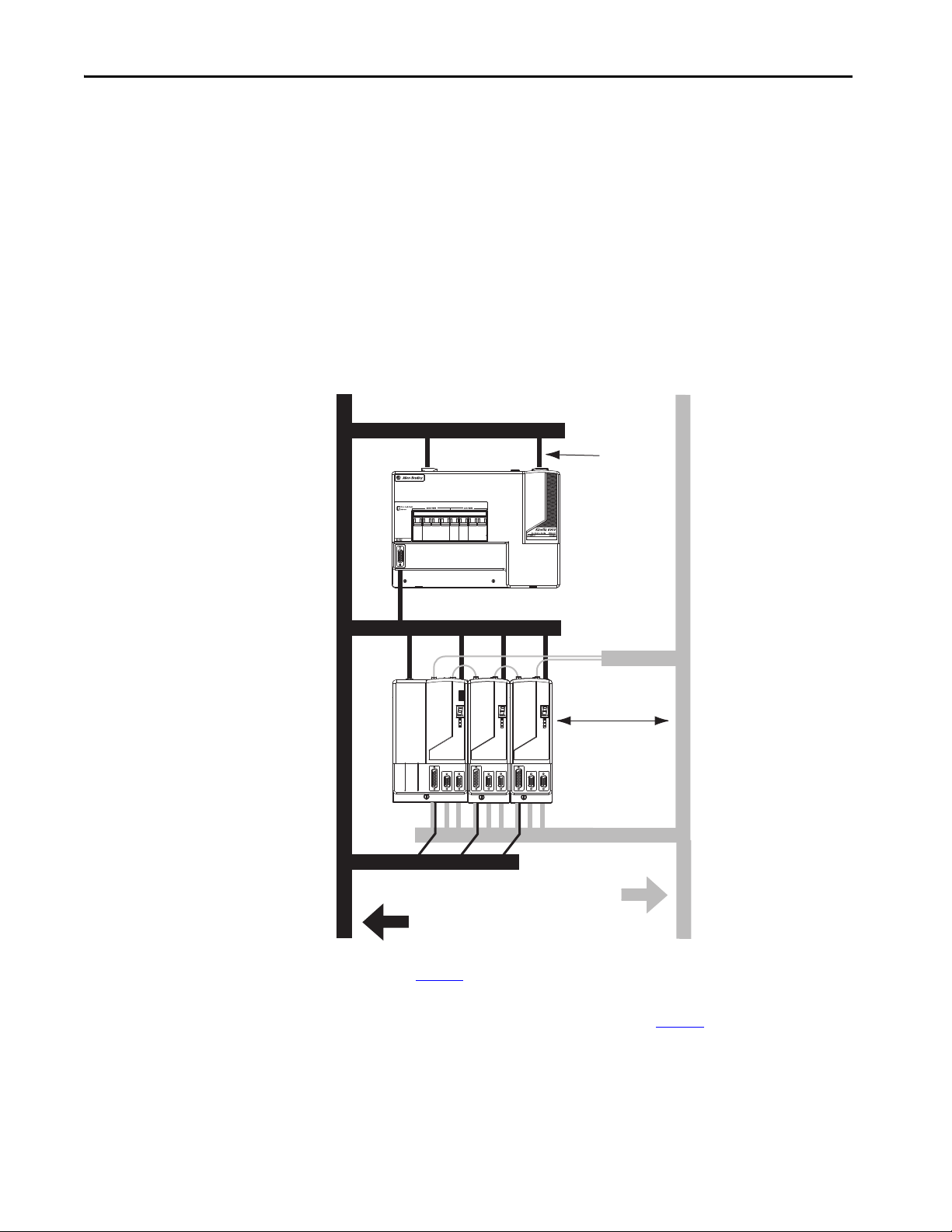
Chapter 2 Plan the Kinetix 6000 Drive System Installation
Line Interface Module
Kinetix 6000
System
Dir ty Wireway Clean Wireway
Motor Power Cables
Very dirty LIM/IAM
(1)
connections must be
shielded with braid
clamp at both ends.
I/O
(2)
and Feedback Cables
No sensitive
(3)
equipment within
150 mm (6.0 in.).
Route 24V DC I/O
shielded cable.
Route encoder/analog/registration
shielded cables.
Fiber-optic Cab le
Observe these guidelines when the 2094-AL09 or 2094-BL02 LIM module is
used in the Bulletin 2094 system and mounted above the IAM module:
• The clean zone (C) is to the right and beneath the Bulletin 2094 system
(gray wireway).
• The dirty zone (D) is to the left and above the Bulletin 2094 system, and
above and below the LIM module (black wireway).
• The LIM VAC output is very dirty (VD). Use shielded cable with a
braid clamp attached at both ends of the cable to reduce the rating to
dirty (D).
• The Sercos fiber-optic cables are immune to electrical noise, but due to
their delicate nature, route them in the clean zone.
Figure 15 - Noise Zones (LIM mounted above IAM module)
D
D
C
D
VD
D
C
C
42 Rockwell Automation Publication 2094-UM001J-EN-P - March 2017
(1) For examples of shield clamp attachment, refer to the System Design for Control of Electrical Noise Reference Manual,
publication GMC-RM001
(2) If drive system I/O cable contains (dirty) relay wires, route cable in dir ty wireway.
(3) When space does not permit the 150 mm (6.0 in.) segregation, use a grounded steel shield instead. For examples, refer to the
System Design for Control of Electrical Noise Reference Manual, publication GMC-RM001
.
.
Page 43

Plan the Kinetix 6000 Drive System Installation Chapter 2
(1)
2094-BL02 or 2094-BLxxS
Line Interface Module
Kinetix 6000
System
Dirty Wireway
Clean Wireway
I/O
(1)
, Feedback, and
Network Cables
Motor and Hybrid Cables
Very Dirty Filter/IAM Connections
Segregated (not in wireway)
Route 24V DC I/O
shielded cable.
Route encoder/analog/registration
shielded cables.
Fiber-optic Cables and
IPIM Digital Input Wires
No sensitive
(2)
equipment within
150 mm (6.0 in.).
Observe these guidelines when your system includes the 2094-SEPM-B24-S
IPIM module. In this example, a 2094-BL02 LIM module is used in the
Bulletin 2094 system and mounted left of the IAM module:
• Establish clean (C) and dirty zones (D) similar to other Bulletin 2094
drive systems.
• The Sercos fiber-optic cables are immune to electrical noise, but due to
their delicate nature, route them in the clean zone.
• IPIM digital input wires are noise sensitive and belong with the fiberoptic cables in the clean zone.
• Ethernet cables are noise sensitive and belong in the clean zone, however,
they are connected only when programming the IPIM module.
• IDM network cables, although noise sensitive by nature, are shielded
and can be routed with the hybrid cables outside of the enclosure.
• The Bulletin 2090 hybrid cable is dirty and belongs in the dirty zone.
This layout is preferred due to the reduced size of the very dirty zone.
Figure 16 - Noise Zones (Bulletin 2094 power rail with IPIM module)
D
D
D
(1) If drive system I/O cable contains (dirty) relay wires, route cable with LIM module I/O cabl e in dirty wireway.
(2) When space does not permit the 150 mm (6.0 in.) segregation, use a grounded steel shield instead. For examples, refer to the
System Design for Control of Electrical Noise Reference Manual, publication GMC-RM001
VD
D
D
CC
.
C
Rockwell Automation Publication 2094-UM001J-EN-P - March 2017 43
Page 44

Chapter 2 Plan the Kinetix 6000 Drive System Installation
(1)
C
C
D
D
VD
(4)
(3)
D
D
C
Dir ty Wireway Clean Wireway
Motor Power Cables
24V Motor
Brake PS
Circuit
Breaker
XFMR
AC
Line Filter
(required
for CE)
DC
Filter
Contac tors
Kinetix 6000 System
(2)
(2)
I/O
(1)
and Feedback Cables
Very Dirty Filter/IAM Connections
Segregated (not in wireway)
Route 24V DC I/O
shielded cable.
Route encoder/analog/registration
shielded cables.
Fiber-optic Cable
Observe these guidelines when individual input power components are used in
the Bulletin 2094 system and the Bulletin 2094 LIM module is not used:
• The clean zone (C) is beneath the Bulletin 2094 system and includes the
I/O wiring, feedback cable, and DC filter (gray wireway).
• The dirty zone (D) is above the Bulletin 2094 system (black wireway)
and includes the circuit breakers, transformer, 24V DC power supply,
contactors, AC line filter, and motor power cables.
• The very dirty zone (VD) is limited to where the AC line (EMC) filter
VAC output jumpers over to the IAM module. Shielded cable is
required only if the very dirty cables enter a wireway.
• The Sercos fiber-optic cables are immune to electrical noise, but due to
their delicate nature, route them in the clean zone.
Figure 17 - Noise Zones (without LIM module)
(1) If drive system I/O cable contains (dirty) relay wires, route cable in dir ty wireway.
(2) When space to the right of the IAM does not permit 150 mm (6.0 in.) segregation, use a grounded steel shield instead. For
examples, refer to the System Design for Control of Electrical Noise Reference Manual, publication GMC-RM001
(3) This is a clean 24V DC available for any device that requires it. The 24V enters the clean wireway and exits to the right.
(4) This is a dirty 24V DC available for motor brakes and contactors. The 24V enters the dirty wireway and exits to the left.
.
44 Rockwell Automation Publication 2094-UM001J-EN-P - March 2017
Page 45

Plan the Kinetix 6000 Drive System Installation Chapter 2
(1)
AC Lin e
Filter
Spare Slots
Dirty Wireway
Clean Wireway
Route dirty wireways directly above the ControlLogix controller chassis
(shielded by the chassis).
Line Filter/Power Supply
Connections Segregated
(not in wireway)
Dirty I/O
(24V DC I/O, AC I/O)
Clean I/O
(Analo g, Encoder
Registration)
Observe these guidelines when installing your Logix5000™ Sercos interface
module:
• The clean zone (C) is beneath the less noisy modules (I/O, analog,
encoder, registration, an so forth (gray wireway).
• The dirty zone (D) is above and below the power supply and noisy
modules (black wireway).
• The Sercos fiber-optic cables are immune to electrical noise, but due to
their delicate nature, route them in the clean zone.
Figure 18 - Noise Zones (ControlLogix chassis)
D
D
C
Cable Categories for Kinetix 6000 Systems
These tables indicate the zoning requirements of cables connecting to the
Kinetix 6000 drive components.
Table 14 - IAM Module (converter side)
Zone Method
Wire/Cable Connector
CTRL 1 and 2 CPD X
DC-/DC+ (unshielded cable)
L1, L2, L3 (shielded cable) X X
L1, L2, L3 (unshielded cable) X
CONT EN- and CONT EN+ (M1 contactor) CED X
DPI DPI X X
IPD
Very
Dirty
X
Dirty Clean
Ferrite
Sleeve
Shielded
Cable
Rockwell Automation Publication 2094-UM001J-EN-P - March 2017 45
Page 46

Chapter 2 Plan the Kinetix 6000 Drive System Installation
Wire/Cable Connector
U, V, W ( motor power) M P X X
COM, PWR (24V DC), filtered
COM, PWR (24V DC), unfiltered
DBRK-, DBRK+ (resistive brake) X
MBRK-, MBRK+ (motor brake) X
MBRK-, MBRK+ (motor brake)
1326AB motors with resolver feedback
COM, PWR (24V DC), safety enable, and
feedback signals for safe torque-off feature
Motor feedback MF X X
Auxiliary feedback AF X X
Registration and analog outputs
Others X
Fiber-optic Rx and Tx No restrictions
(1) This is a clean 24V DC available for any device that requires it.
(2) This is a dirty 24V DC available for motor brakes and contactors.
Table 15 - AM Module or Axis Module (inverter side)
Very
Dirty
(1)
(2)
BC
BC X X
STO X
IOD
Zone Method
Dirty Clean
Ferrite
Sleeve
X
X
XX
Shielded
Cable
Table 16 - Line Interface Module (LIM)
Zone Method
Wire/Cable Connector
Very
Dirty
Dirty Clean
Ferrite
Sleeve
VAC line (main input) IPL X
Aux power input APL X
VAC load (shielded option)
VAC load (unshielded option) X
OPL
XX
Control power outpu t CP L X
MBRK PWR, MBRK COM P1L/PSL X
Status I/O IOL X
Aux power output P2L X
Table 17 - Shunt Module
Zone Method
Wire/Cable Connector
COL, DC+ (shielded option)
RC
COL, DC+ (unshielded option) X
Thermal switch TS X X
Fan (if present) N/A X
Very
Dirty
Dirty Clean
Ferrite
Sleeve
XX
Shielded
Cable
Shielded
Cable
46 Rockwell Automation Publication 2094-UM001J-EN-P - March 2017
Page 47

Table 18 - IDM Power Interface Module (IPIM)
Plan the Kinetix 6000 Drive System Installation Chapter 2
Wire/Cable
Hybrid DC bus power, control power,
inter-module communication, and Safe Torque Off
Enable input X X
Fiber-optic No restrictions
Ethernet network X X
IDM network
(1) There is no option for making your own hybrid power or IDM network cables.
(1)
(1)
Very Dirty Dirty Clean Ferrite Sleeve Shielded Cable
Zone Method
XX
XX
Table 19 - Resistive Brake Module (RBM)
Wire/Cable Connections
Resistive brake module coil power TB3-6 and TB3-7 X
Resistive brake module I/O
Resistive brake module drive and motor power TB1 and TB2 X X
230V power TB4 X
TB1-1…TB1-5
and TB3-8
Very Dirty Dirty Clean Ferrite Sleeve Shielded Cable
Zone Method
X
Noise Reduction Guidelines for Drive Accessories
Refer to this section when mounting an AC (EMC) line filter or external shunt
module for guidelines designed to reduce system failures caused by excessive
electrical noise.
AC Line Filters
Observe these guidelines when mounting your AC (EMC) line filter (refer to
the figure on page 44
• Mount the AC line filter on the same panel as the Kinetix 6000 drive
and as close to the power rail as possible.
• Good HF bonding to the panel is critical. For painted panels, refer to
the examples on page 35
• Segregate input and output wiring as far as possible.
IMPORTANT CE test certification applies only to AC line filter and single power rail.
for an example):
.
Sharing a line filter with multiple power rails can perform satisfactorily, but
the user takes legal responsibility.
Rockwell Automation Publication 2094-UM001J-EN-P - March 2017 47
Page 48

Chapter 2 Plan the Kinetix 6000 Drive System Installation
C
D
D
D
D
D
VD
C
VD
D
1394 Digital Servo Controller
300W Shunt Module
BULLETIN 1394 300W SHUNT MODULE
ALLEN-BRADLEY
FOR USE WITH 1394-SJT22-X SYSTEM MODULE
CAT. PART SER.
INPUT DC INPUT AC
FOR FUSE REPLACEMENT USE:
BUSSMAN CAT. NO.
R
(1)
Line Interface Module
Kinetix 6000
System
Dirty Wireway
Clean Wireway
Motor Power Cables
Very Dirty Connections Segregated
(not in wireway)
Customer-supplied
Metal Enclosure
150 mm (6.0 in.)
clearance (min) on all four
sides of the shunt module.
Enclosure
2094-BSP2
Shunt Module
Shunt Power Wiring Methods:
Twisted pair in conduit (1st choice).
Shielded twisted pair (2nd choice).
Twisted pair, two twists per foot (min) (3rd choice).
Metal Conduit
(where re quired
by local code)
I/O and Feedback Cables
Shunt thermal Switch and Fan Wires (when present)
No sensitive
equipment within
150 mm (6.0 in.).
Route 24V DC I/O
shielded cable.
Route encoder/analog/registration
shielded cables.
External Shunt Modules
Observe these guidelines when mounting your external shunt module outside
the enclosure:
• Mount circuit components and wiring in the very dirty zone or in an
external shielded enclosure. Run shunt power and fan wiring inside
metal conduit to minimize the effects of EMI and RFI.
• Mount resistors (other than metal-clad) in a shielded and ventilated
enclosure outside the cabinet.
• Keep unshielded wiring as short as possible. Keep shunt wiring as flat to
the cabinet as possible.
• Route thermal switch and fan wires separate from shunt power.
Figure 19 - External Shunt Module Outside the Enclosure
48 Rockwell Automation Publication 2094-UM001J-EN-P - March 2017
Page 49

Plan the Kinetix 6000 Drive System Installation Chapter 2
C
D
D
D
D
D
VD
C
VD
1394 Digital Servo Controller
300W Shunt Module
BULLETIN 1394 300W SHUNT MODULE
ALLEN-BRADLEY
FOR USE WITH 1394-SJT22-X SYSTEM MODULE
CAT. PART SER.
INPUT DC INPUT AC
FOR FUSE REPLACEMENT USE:
BUSSMAN CAT. NO.
R
D
Line Interface Module
Kinetix 6000
System
Dirty Wireway
Clean Wireway
Motor Power Cables
Enclosure
2094-BSP2
Shunt Module
I/O and Feedback Cables
150 mm (6.0 in.)
clearance (min) on all four
sides of the shunt module.
Shunt thermal Switch and Fan Wires (when present)
Very Dirty Connections Segregated
(not in wireway)
Shunt Power Wiring Methods:
Twisted pair in conduit (1st choice).
Shielded twisted pair (2nd choice).
Twisted pair, two twists per foot (min) (3rd choice).
No sensitive
equipment within
150 mm (6.0 in.).
Route 24V DC I/O
shielded cable.
Route encoder/analog/registration
shielded cables.
When mounting your shunt module inside the enclosure, follow these
additional guidelines:
• Mount metal-clad modules anywhere in the dirty zone, but as close to
the Bulletin 2094 drive system as possible.
• Route shunt power wires with motor power cables.
• Keep unshielded wiring as short as possible. Keep shunt wiring as flat to
the cabinet as possible.
• Separate shunt power cables from other sensitive, low voltage signal
cables.
Figure 20 - External Shunt Module Inside the Enclosure
Rockwell Automation Publication 2094-UM001J-EN-P - March 2017 49
Page 50

Chapter 2 Plan the Kinetix 6000 Drive System Installation
C
D
D
D
VD
D
D
D
C
Line Interface Module
Kinetix 6000
System
Dirty Wireway
Clean Wireway
Motor Power Cables
Very Dirty LIM/IAM Connections
Segregated (not in wireway)
RBM I/O
LIM VAC Input Power
IAM/AM Feedback and
(clean) I/O
LIM and IAM/AM (dirty) I/O
No sensitive
equipment within
150 mm (6.0 in.).
Fiber-optic Cable
Resistive Brake Modules
Observe these guidelines when mounting your RBM module:
• Mount circuit components and wiring in the dirty zone or in an external
shielded enclosure. If mounting the RBM module in a separate
ventilated shielded enclosure, run wiring inside metal conduit to
minimize the effects of EMI and RFI.
•Keep unshielded wiring as short as possible. Keep wiring as flat to the
cabinet as possible.
• Route RBM module power and I/O cables separate from other sensitive
low voltage signal cables.
Figure 21 - Noise Zones (RBM mounted above AM module)
Motor Brake and Thermal Switch
The thermal switch and brake are mounted inside the motor, but how you
connect to the axis module depends on the motor series.
Refer to Wire the Motor/Resistive Brake (BC) Connector on page 113
wiring guidelines. Refer to Axis Module/Rotary Motor Wiring Examples
beginning on page 198
combination.
50 Rockwell Automation Publication 2094-UM001J-EN-P - March 2017
for the interconnect diagram of your drive/motor
for
Page 51

Chapter 3
Mount the Kinetix 6000 Drive System
This chapter provides the system installation procedures for mounting your
Kinetix® 6000 drive components on the Bulletin 2094 power rail.
Top ic Pa ge
Before You Begin 51
Determine Mounting Order 52
Mount Modules on the Power Rail 54
This procedure assumes you have prepared your panel, mounted your Bulletin
2094 power rail, and understand how to bond your system. For installation
instructions regarding equipment and accessories not included here, refer to
the instructions that came with those products.
Before You Begin
SHOCK HAZARD: To avoid hazard of electrical shock, perform all mounting
and wiring of the Bulletin 2094 power rail and drive modules prior to
applying power. Once power is applied, connector terminals can have
voltage present even when not in use.
ATT EN TI ON : Plan the installation of your system so that you can perform all
cutting, drilling, tapping, and welding with the system removed from the
enclosure. Because the system is of the open type construction, be careful to
keep any metal debris from falling into it. Metal debris or other foreign
matter can become lodged in the circuitry, which can result in damage to
components.
Before you begin, consider your Bulletin 2094 power rail installation and using
2094 mounting brackets.
Using the 2094 Mounting Brackets
You can use Bulletin 2094 mounting brackets to mount the power rail or LIM
module over the AC line filter. Refer to the 2094 Mounting Brackets
Installation Instructions, publication 2094-IN008
brackets with your Kinetix 6000 drive system.
, when using mounting
Rockwell Automation Publication 2094-UM001J-EN-P - March 2017 51
Page 52

Chapter 3 Mount the Kinetix 6000 Drive System
Installing the 2094 Power Rail
The Bulletin 2094 power rail comes in lengths to support one IAM module
and up to seven additional AM/IPIM modules, or up to six additional AM/
IPIM modules and one shunt module. The connector pins for each slot are
covered by a protective cover. The cover is designed to protect the pins from
damage and make sure that no foreign objects lodge between the pins during
installation. Refer to the Kinetix 6000 Power Rail Installation Instructions,
publication 2094-IN003
ATT EN TI ON : To avoid damage to the power rail during installation, do not
remove the protective covers until the module for each slot is ready for
mounting.
The Kinetix 6000M integrated drive-motor (IDM) system is supported by
Bulletin 2094 (400V-class) power rail configurations. You can mount up to
four IDM power interface (IPIM) modules on the Bulletin 2094 power rail.
Refer to the Kinetix 6000M Integrated Drive-Motor System User Manual,
publication 2094-UM003
, when installing your power rail.
, for more information.
Determine Mounting Order
Mount IAM, AM/IPIM, shunt, and slot-filler modules in the order (left to
right) as shown in Figure 22
. Mount axis modules and the IPIM module
according to power utilization (highest to lowest) from left to right starting
with the highest power utilization.
Power utilization is the average power (kW) consumed by a servo axis. If
Motion Analyzer software was used to size the axis, the calculated axis power
required can be used for the power utilization value. If Motion Analyzer
software was not used, you can use the continuous power value (kW) for each
module to determine mounting order.
Table 20 - Kinetix 6000 (200V-class) Axis Modules
Attribute 2094-AMP5-S 2094-AM01-S 2094-AM02-S 2094-AM03-S 2094-AM05-S
Continuous Power
Output, nom
Table 21 - Kinetix 6000 (400V-class) Axis Modules
Attribute 2094-BMP5-S 2094-BM01-S 2094-BM02-S 2094-BM03-S 2094-BM05-S
Continuous Power
Output, nom
Table 22 - Kinetix 6000M (400V-class) IPIM Module
1.2 kW 1.9 kW 3.4 kW 5.5 kW 11.0 kW
1.8 kW 3.9 kW 6.6 kW 13.5 kW 22.0 kW
Attribute 2094-SEPM-B24-S
Continuous Power Output, nom 15.0 kW
52 Rockwell Automation Publication 2094-UM001J-EN-P - March 2017
Page 53

Figure 22 - Module Mounting Order Example
Highest Power Utilization
Lowest Power Utilization
Integrated Axis Module
2094-BC02-M02-x
IPIM Module
2094-SEPM-B24-S
Axis Module
2094-BM02-x
Axis Module
2094-BM02-x
Axis Module
2094-BM01-x
Axis Module
2094-BM01-x
Shunt Module
2094-BSP2
Slot-filler Module
2094-PRF
Mount the Kinetix 6000 Drive System Chapter 3
IMPORTANT The IAM module must be positioned in the leftmost slot of the power rail. Position your
AM/IPIM modules, shunt module, and slot-filler modules to the right of the IAM module.
The shunt module must be installed to the right of the last AM/IPIM module. Only slot-
filler modules can be installed to the right of the shunt module.
Do not mount the shunt module on power rails with a follower IAM module. Common-bus
follower IAM modules disable the internal, rail mounted, and external shunt modules.
SHOCK HAZARD: To avoid personal injury due to electrical shock, place a
2094-PRF slot-filler module in all empty slots on the power rail. Any power
rail connector without a module installed disables the Bulletin 2094 system;
however, control power is still present.
Rockwell Automation Publication 2094-UM001J-EN-P - March 2017 53
Page 54

Chapter 3 Mount the Kinetix 6000 Drive System
Slots for additional axis modules,
shunt module, or slot-filler modules.
Power Rail Sl ot
Mounting Bracket
Power Rail
Kinetix 6000 IAM, AM, IPIM,
Shunt, or Slot-filler Module
(IAM module is shown)
Mount Modules on the
Power Rail
Follow these steps to mount the IAM, AM, IPIM, shunt, and slot-filler
modules.
TIP All modules mount to the power rail by using the same technique; however,
only the IAM module is used in the examples.
1. Remove the protective covers from the power rail connectors.
IMPORTANT The IAM module must be positioned in the leftmost slot of the
power rail. Position your axis modules, shunt module, and slot-filler
modules to the right of the IAM module.
2. Determine the next available slot and module for mounting.
ATT EN TI ON : To avoid damage to the pins on the back of each IAM,
AM, IPIM, shunt, and slot-filler module and to make sure that
module pins mate properly with the power rail, hang modules as
shown in step 3
through step 6.
The power rail must be mounted vertically on the panel before
hanging modules on the power rail. Do not mount modules if the
power rail is horizontal.
3. Hang the mounting bracket from the slot on the power rail.
54 Rockwell Automation Publication 2094-UM001J-EN-P - March 2017
Page 55

Mount the Kinetix 6000 Drive System Chapter 3
Guide Pin
Holes
Power rail (side view)
in upright vertical position.
Guide Pins
Pivot module downward
and align with guide pins.
Kinetix 6000 IAM, AM, IPIM, Shunt,
or Slot-filler Module, Side View
(IAM module is shown)
Kinetix 6000 IAM, AM, IPIM, Shunt,
or Slot-filler Module, Rear View
(IAM module is shown)
Power Rail
Bracket secured in slot.
Kinetix 6000 IAM, AM, IPIM,
Shunt, or Slot-filler Module
(IAM module is shown)
4. Pivot module downward and align the guide pins on the power rail with
the guide pin holes in the back of the module.
TIP The IAM module can have two or three power rail connectors and guide
pins, the AM module can have one or two, all other modules have one.
5. Gently push the module against the power rail connectors and into the
final mounting position.
Rockwell Automation Publication 2094-UM001J-EN-P - March 2017 55
Page 56
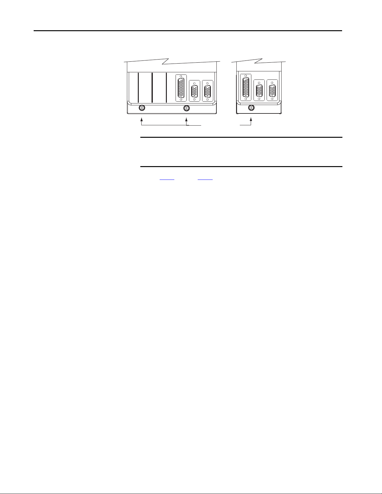
Chapter 3 Mount the Kinetix 6000 Drive System
Bottom front view of
single-wide AM, IPIM, shunt,
or slot-filler module
(AM module is shown).
Bottom front view of
double-wide IAM or AM module
(AM module is shown).
Mounting Screws
6. Use 2.26 N•m (20 lb•in) torque to tighten the mounting screws.
IMPORTANT There are two mounting screws when mounting 2094-AC32-M05-x,
2094-BC04-M03-x, and 2094-BC07-M05-x (double-wide) IAM modules,
and 2094-BM03-x and 2094-BM05-x (double-wide) AM modules.
Repeat step 1
through step 6 for each AM, IPIM, shunt, or slot-filler module in
your Bulletin 2094 drive system
56 Rockwell Automation Publication 2094-UM001J-EN-P - March 2017
Page 57

Chapter 4
Connector Data and Feature Descriptions
This chapter illustrates drive connectors and indicators, including connector
pinouts, and provides descriptions for Kinetix® 6000 drive features.
Top ic Pa ge
2094 IAM/AM Module Connector Data 58
Control Signal Specifications 67
Power and Relay Specifications 71
Feedback Specifications 78
For the Kinetix 6000M integrated drive-motor (IDM) unit and IDM power
interface module (IPIM) connector locations and signal descriptions, refer to
the Kinetix 6000M Integrated Drive-Motor System User Manual, publication
2094-UM003
.
Rockwell Automation Publication 2094-UM001J-EN-P - March 2017 57
Page 58

Chapter 4 Connector Data and Feature Descriptions
Kinetix 6000 IAM Module, Top View
(2094-AC05-M01-S module is shown)
Kinetix 6000 IAM Module, Front View
(2094-AC05-M01-S module is shown)
2094 IAM/AM Module
Connector Data
1 2
4
3
2
1
CTRL 2
CTRL 1
1 2 3 4 5 6
DC-
DC+
L3
L2
L1
1 2
CONT EN-
CONT EN+
1 2 3 4 5 6 7 8 9
RX
DPI
MBRK +
MBRK -
DBRK -
DBRK +
COM
PWR
W
V
U
1 2 3 4
1 2 3 4 5 6
TX
Use these illustrations to identify the connectors and indicators for the
IAM/AM modules. Sercos interface and Ethernet network connectors for the
Kinetix 6000M IPIM module are also shown. For the remainder of the IPIM
module features and indicators, refer to the Kinetix 6000M Integrated DriveMotor System User Manual, publication 2094-UM003
.
Although the physical size of the 400V-class module is larger than the
200V-class module, the location of the features and indicators is identical.
Figure 23 - Integrated Axis Module Features and Indicators
14
5
6
7
BAUD
RATE
8
13
15
16
17
18
19
20
9
10
12
11
Item Description Item Description
1 Safe torque- off (STO) connec tor 11 Sercos receive (Rx) connec tor
2 Contactor enable (CED) connector 12 Mounting screw
3 DC bus/AC input power (IPD) connector 13 I/O (IOD) connector
4 Control power (CPD) connector 14 Sercos node address switch
5 Motor cable shield clamp 15 Seven-segment fault status indicator
6 Motor power (MP) connector 16 Drive status indicator
7 Motor/resistive brake (BC) connector 17 COMM status indicator
Sercos communication rate and
8
optical power switches
18 Bus status indicator
9 Sercos transmit (Tx) connector 19 Motor feedback (MF) connector
10 DPI connector 20 Auxiliary feedback (AF) connector
58 Rockwell Automation Publication 2094-UM001J-EN-P - March 2017
Page 59

Figure 24 - Axis Module Features and Indicators
BAUD
RATE
TX
RX
W
V
U
MBRK -
MBRK +
COM
PWR
DBRK -
DBRK +
1 2 3 4
1 2 3 4 5 6
1 2 3 4 5 6 7 8 9
1
2
3
4
5
6
7
15
11
12
13
14
16
9
10
8
Kinetix 6000 AM Module, Top View
(2094-AM01-S module is shown)
Kinetix 6000 AM Module, Front View
(2094-AM01-S module is shown)
2094-SEPM-B24-S
IPIM Module, Top View
2094-SEPM-B24-S
IPIM Module, Bottom View
Connector Data and Feature Descriptions Chapter 4
Item Description Item Description
1 Safe torque-off (STO) connector 9 Mounting screw
2 Motor cable shield clamp 10 I/O (IOD) connector
3 Motor power (MP) connector 11 Seven-segment fault status indicator
4 Motor/resistive brake (BC) connector 12 Drive status indicator
5 Sercos communication rate and optical power switches 13 COMM status indicator
6 Sercos transmit ( Tx) connector
7 Sercos receive (Rx) connector
8 Ethernet (PORT1 and PORT 2) connectors
(1) The Rx and Tx Sercos connectors on the Kinetix 6000M IPIM module are in the same position as on the Kinetix 6000 AM modules. For the remainder of the IPIM module
features and indicators, refer to the Kinetix 6000M Integrated Drive-Motor System User Manual, publication 2094-UM003
(2) The Kinetix 6000M IPIM module has two Ethernet ports. These ports are used only for connecti ng to the EtherNet/IP network for Logix5000™ programming.
(1)
(1)
(2)
14 Bus status indicator
15 Motor feedback (MF) connector
16 Auxiliar y feedback (AF) connector
.
Table 23 - Kinetix 6000 IAM/AM Module Connectors
Designator Description Connector Module
IOD User I/O (drive) 26-pin high-density D-shell (female) IAM/AM
MF Motor feedback 15-pin high-density D-shell (female) IAM/AM
AF Auxiliary feedback 15-pin high-density D-shell (male) IAM/AM
CPD Control input power (drive) 2-position plug/header IAM
IPD VAC input power (drive) and DC bus 6-position plug/header IAM
CED Contactor enable 2-position plug/header IAM
MP Motor power 4-position plug/header IAM/AM
BC Motor/Resistive brake 6-position plug/header IAM/AM
STO Safe torque-off 9-position plug/header IAM/AM
Tx and Rx Sercos transmit and receive Sercos fiber-optic (2) IAM/AM
DPI DPI DPI IAM
Rockwell Automation Publication 2094-UM001J-EN-P - March 2017 59
Page 60

Chapter 4 Connector Data and Feature Descriptions
1
2
3
4
5
67
8
9
1
Motion-allowed Jumper
Wiri ng Plug Header
Kinetix 6000 IAM/AM Module
(AM module is shown)
Safe Torque-off
(STO) Connector
Safe Torque-off Connector Pinout
Each 2094-xCxx-Mxx-S IAM module and 2094-xMxx-S AM module ships
with the (9-pin) wiring-plug header and motion-allowed jumper installed in
the safe torque-off (STO) connector. With the motion-allowed jumper
installed, the safe torque-off feature is not used.
Figure 25 - Motion-allowed Jumper
Headers in this table extend the safe torque-off (STO) connector signals for
use in wiring single and multiple safe torque-off drive configurations, or to
defeat (not use) the safe torque-off feature.
Table 24 - IAM/AM Safe Torque-off 9-pin (STO) Connector
Safe Torque-off (STO)
Connector Pin
1
2 Other side of the normally-closed monitoring contact of relay 2 FDBK2-
3 One side of the normally-closed monitoring contact of relay 1 FDBK1+
4 Other side of the normally-closed monitoring contact of relay 1 FDBK1-
5 Safety enable 2 input SAFET Y ENABLE2+
6 Return for safety enable power (both inputs) SAFETY ENABLE-
7 Safety enable 1 input SAFET Y ENABLE1+
8
9 Power return used for continuous enable of safety function 24V_COM
Applies to These STO Connector Headers Description Signal
One side of the normally-closed monitoring contact of relay 2 FDBK2+
• Wiring plug header used in single-drive
applications
• First-drive wiring header
(catalog number 2090-XNSM-W)
used in multiple-drive applications
• Wiring plug header
• Motion-allowed jumper
Power for continuous enable of the safety function, 500 mA max 24V+
IMPORTANT Pins STO-8 and STO-9 (24V+) are used by only the motion-allowed jumper.
When wiring to the wiring-plug header, the 24V supply must come from an
external source.
Refer to the Kinetix Safe Torque-off Feature Safety Reference Manual,
60 Rockwell Automation Publication 2094-UM001J-EN-P - March 2017
publication GMC-RM002
headers.
, for more information on wiring safe torque-off
Page 61
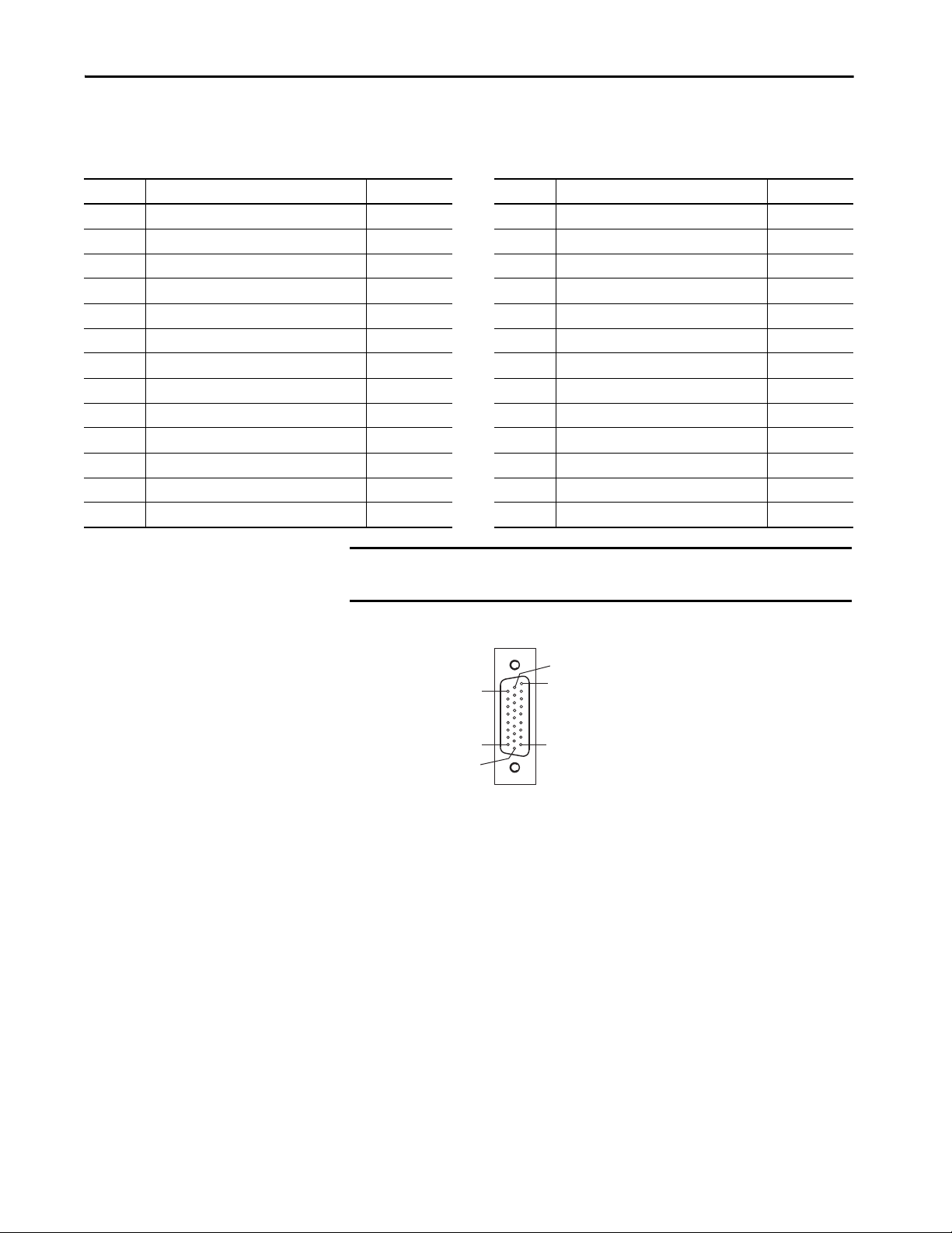
Connector Data and Feature Descriptions Chapter 4
Pin 18
Pin 26
Pin 1
Pin 9
Pin 10
Pin 19
I/O Connector Pinout
Table 25 - IAM/AM I/O 26-pin (IOD) Connector
IOD Pin Description Signal IOD Pin Description Signal
1 Hardware enable 24V DC power supply +24V_PWR 14 High speed registration 1 input REG1
2 Hardware enable input ENABLE 15 Common for registration REG_COM
3 Common +24V_COM 16 24V registration power REG_24V
4 Home switch 24V DC power supply +24V_PWR 17 High speed registration 2 input REG2
5 Home switch input HOME 18 Common for registration REG_COM
6 Common +24V_COM 19 Reserved –
7 Positive overtravel 24V DC power supply +24V_PWR 20 Reserved –
8 Positive overtravel limit switch input OT+ 21 Reserved –
9 Common +24V_COM 22 Reserved –
10 Negative overtravel 24V DC power supply +24V_PWR 23 Analog output 0 DAC0
11 Negative overtravel limit switch input OT- 24 Analog output common DAC_COM
12 Common +24V_COM 25 Analog output 1 DAC1
13 24V registration power REG_24V 26 Analog output common DAC_COM
IMPORTANT Signals +24V_PWR and +24V_COM are a 24V DC source you can use only
for the inputs listed above.
Figure 26 - Pin Orientation for 26-pin I/O (IOD) Connector
Rockwell Automation Publication 2094-UM001J-EN-P - March 2017 61
Page 62

Chapter 4 Connector Data and Feature Descriptions
Motor Feedback Connector Pinout
Table 26 - Stegmann Hiperface (SRS/SRM)
MF Pin Description Signal MF Pin Description Signal
1 Sine differential input+ SIN+ 9 Reserved –
2 Sine differential input- SIN- 10 Hiperface data channel DATA-
3 Cosine differential input+ COS+ 11 Motor thermal switch (normally closed)
4 Cosine differential input- COS- 12 Reserved –
5 Hiperface data channel DATA+ 13 Reserved –
6 Common ECOM 14 Encoder power (+5V) EPWR_5V
7 Encoder power (+9V) EPWR_9V
(1)
15 Reserved –
8Reserved –
(1) Determine which power supply your encoder requires and connect to only the specified supply. Do not make connections to both.
(2) Not applicable unless the motor has integrated thermal protection. Common (TS-) signal for thermal switch is tied to MF-6 (ECOM) in Bulletin 2090 cables.
Table 27 - TTL or Sine/Cosine with Index Pulse and Hall Commutation
MF Pin Description Signal MF Pin Description Signal
1 AM+ / Sine differential input+ AM+ / SIN+ 9 Reserved –
2 AM- / Sine differential input- AM- / SIN- 10 Index pulse- IM-
3 BM+ / Cosine differential input+ BM+ / COS+ 11 Motor thermal switch (normally closed)
4 BM- / Cosine differential input- BM- / COS- 12 Single-ended 5V hall effect commutation S1
5 Index pulse+ IM+ 13 Single-ended 5V hall effect commutation S2
6 Common ECOM 14 Encoder power (+5V) EPWR_5V
7 Encoder power (+9V) EPWR_9V
8 Single-ended 5V hall effect commutation S3
(1) Determine which power supply your encoder requires and connect to only the specified supply. Do not make connections to both.
(2) Not applicable unless the motor has integrated thermal protection. Common (TS-) signal for thermal switch is tied to MF-6 (ECOM) in Bulletin 2090 cables.
(1)
15 Reserved –
(2)
(2)
TS+
TS+
(1)
(1)
ATT EN TI ON : To avoid damage to components, determine which power supply
your encoder requires and connect to either the 5V or 9V supply, but not both.
Table 28 - Resolver Transmitter (transformation ratio = 0.25)
MF Pin Description Signal MF Pin Description Signal
1 Sine differential input+ S2 9 Reserved –
2 Sine differential input- S4 10 Resolver excitation R2
3 Cosine differential input+ S1 11 Motor thermal switch (normally closed)
4 Cosine differential input- S3 12 Reserved –
5 Resolver excitation R1 13 Reserved –
6 Common ECOM 14 Reserved –
7 Reserved – 15 Reserved –
8Reserved –
(1) Not applicable unless the motor has integrated thermal protection. Common (TS-) signal for thermal switch is tied to MF-6 (ECOM) in Bulletin 2090 cables.
(2) If using 1326AB (resolver-based) motors, use 2090-K6CK-D15MF Low-profile Connector Kits that connect the filtered thermal switch (pins 16 and 17) to MF-11 and MF-6.
62 Rockwell Automation Publication 2094-UM001J-EN-P - March 2017
(1) (2)
TS+
Page 63
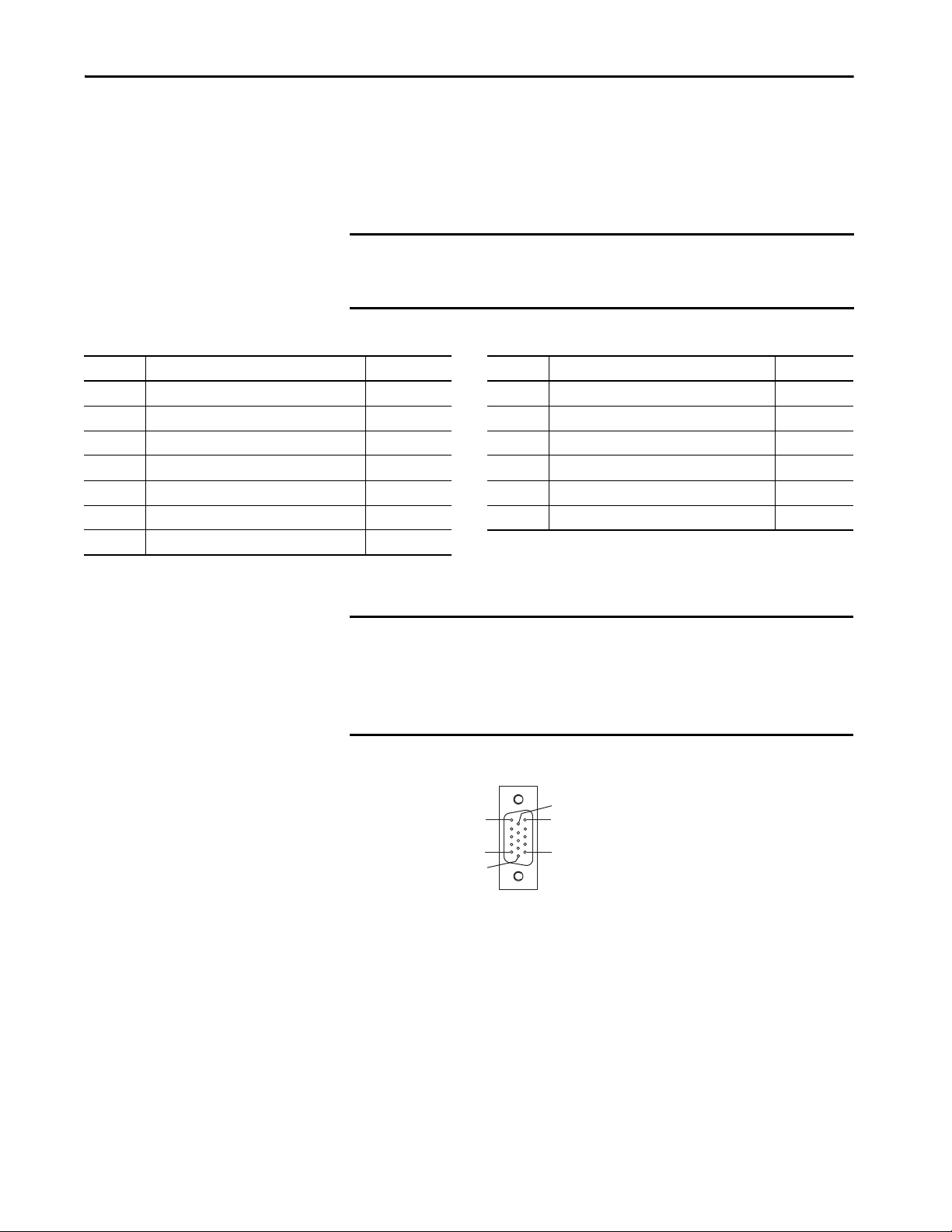
Connector Data and Feature Descriptions Chapter 4
Pin 11
Pin 6
Pin 15
Pin 1
Pin 10
Pin 5
Kinetix 6000 drives do not support Heidenhain EnDat high-resolution
feedback; however, you can use the 2090-K6CK-KENDAT feedback module
to convert Heidenhain EnDat high-resolution feedback to Stegmann
Hiperface. Pin numbers in the table below refer to pins in the feedback
module.
IMPORTANT Only 2094-xCxx-Mxx-S and 2094-xMxx-S drives with firmware revision 1.116
or later support the use of 2090-K6CK-KENDAT feedback modules for
Heidenhain EnDat feedback.
Table 29 - Heidenhain EnDat
Pin Description Signal Pin Description Signal
1 Sine differential input+ SIN+ 8 Serial data clock signal - CLK-
2 Sine differential input- SIN- 9 Serial data differential signal+ DATA+
3 Cosine differential input+ COS+ 10 Serial data differential signal - DATA-
4 Cosine differential input- COS- 11 Motor thermal switch+
5 Encoder power (+5V) EPWR_5V 12 Motor thermal switch-
6 Common ECOM 13 Reserved –
7 Serial data clock signal + CLK+
(1) Not applicable unless the motor has integrated thermal protection.
(2) When used with Allen-Bradley® motors and Bulletin 2090 cables, pin 12 is reserved.
(1)
(2)
TS+
TS-
IMPORTANT Combined motor-power cable length for all axes on the same DC bus must
not exceed 240 m (787 ft) with 460V systems or 160 m (525 ft) with 230V
systems. Drive-to-motor power cables must not exceed 90 m (295.5 ft).
System performance was tested at these cable length specifications. These
limitations also apply when meeting CE requirements.
Figure 27 - Pin Orientation for 15-pin Motor Feedback (MF) Connector
Rockwell Automation Publication 2094-UM001J-EN-P - March 2017 63
Page 64

Chapter 4 Connector Data and Feature Descriptions
Auxiliary Feedback Connector Pinout
For TTL devices, the position count increases when A leads B. For sinusoidal
devices, the position count increases when cosine leads sine.
Table 30 - Stegmann Hiperface (SRS and SRM only)
AF Pin Description Signal AF Pin Description Signal
1 Sine differential input+ SIN+ 9 Reserved –
2 Sine differential input- SIN- 10 Hiper face data channel DATA-
3 Cosine differential input+ COS+ 11 Reserved –
4 Cosine differential input- COS- 12 Reserved –
5 Hiperface data channel DATA+ 13 Reserved –
6 Common ECOM 14 Encoder power (+5V) EPWR_5V
7 Encoder power (+9V) EPWR_9V
8Reserved –
(1) Determine which power supply your encoder requires and connect to only the specified supply. Do not make connections to both.
(1)
15 Reserved –
(1)
Table 31 - TTL or Sine/Cosine with Index Pulse
AF Pin Description Signal AF Pin Description Signal
1 A+ / Sine differential input+ A+ / SIN+ 9 Reserved –
2 A- / Sine differential input- A- / SIN- 10 Index pulse- I-
3 B+ / Cosine differential input+ B+ / COS+ 11 Reser ved –
4 B- / Cosine differential input- B- / COS- 12 Reserved –
5 Index pulse+ I+ 13 Reser ved –
6 Common ECOM 14 Encoder power (+5V) EPWR_5V
7 Encoder power (+9V) EPWR_9V
8Reserved –
(1) Determine which power supply your encoder requires and connect to only the specified supply. Do not make connections to both.
(1)
15 Reserved –
ATT EN TI ON : To avoid damage to components, determine which power
supply your encoder requires and connect to either the 5V or 9V supply, but
not both.
Figure 28 - Pin Orientation for 15-pin Auxiliary Feedback (AF) Connector
Pin 6
Pin 11
Pin 1
(1)
Pin 15
64 Rockwell Automation Publication 2094-UM001J-EN-P - March 2017
Pin 5
Pin 10
Page 65

Connector Data and Feature Descriptions Chapter 4
IAM Input Connector Pinout
Table 32 - Control Power Connector
CPD Pin Description Signal
1
2CTRL 1
Control power VAC input
Table 33 - DC Bus and Input Power Connector
IPD Pin Description Signal
1
2DC+
3 Chassis ground.
An integral, unregulated power supply, consisting of AC line input,
three-phase bridge rectifier, and filter capacitors.
CTRL 2
DC-
4
5L2
6L1
Three-phase input power.
L3
Table 34 - Contactor Enable Connector
CED Pin Description Signal
1
2 CONT EN+
Relay-driven dry contact used in the control string for a threephase power contactor.
CONT E N-
Rockwell Automation Publication 2094-UM001J-EN-P - March 2017 65
Page 66

Chapter 4 Connector Data and Feature Descriptions
IAM and AM Motor Power and Brake Connector Pinout
Table 35 - Motor Power Connector
MP Pin Description Signal
4 Chassis ground
3
2V
1U
Three-phase motor power
W
IMPORTANT Combined motor-power cable length for all axes on the same DC bus must
not exceed 240 m (787 ft) with 460V systems or 160 m (525 ft) with 230V
systems. Drive-to-motor power cables must not exceed 90 m (295.5 ft).
System performance was tested at these cable length specifications. These
limitations also apply when meeting CE requirements.
Table 36 - Motor Brake/Resistive Brake Connector
BC Pin Description Signal
6
5MBRK+
4 Motor brake common COM
3
2
1DBRK+
Motor brake connections
+24V brake input power
(from LIM module or customer supplied)
RBM module connections
(from RBM module and safety string)
MBRK-
PWR
DBRK-
66 Rockwell Automation Publication 2094-UM001J-EN-P - March 2017
Page 67

Connector Data and Feature Descriptions Chapter 4
Control Signal Specifications
This section provides a description of the Kinetix 6000 drive
I/O (IOD), communication, contactor enable (CED), brake (BC), and
control power (CPD) connectors.
Digital Inputs
Two fast registration inputs and four other inputs are available for the machine
interface on the IAM module and AM module. Each IAM and AM module
supplies 24V DC @ 250 mA for the purpose of registration, home, enable,
over-travel positive, and over-travel negative inputs. These are sinking inputs
that require a sourcing device. A 24V DC power and common connection is
provided for each input.
IMPORTANT To improve registration input EMC performance, refer to the System Design
for Control of Electrical Noise Reference Manual, publication GMC-RM001
IMPORTANT Over-travel limit input devices must be normally closed.
Table 37 - Understanding Digital Inputs
IOD Pin Signal Description Capture Time
IOD-2 ENABLE
IOD-5 HOME
IOD-14
IOD-17
IOD-8
IOD-11
REG1
REG2
OT+
OT-
Optically isolated, single-ended active high signal. Current loading is nominally 10 mA. A 24V DC
input is applied to this terminal to enable each axis.
Optically isolated, single-ended active high signal. Current loading is nominally 10 mA. Home
switch (normally open contact) inputs for each axis require 24V DC (nominal).
Fast registration inputs are required to inform the motor interface to capture the positional
information with less than 3 µs uncertainty. Optically isolated, single-ended active high signal.
Current loading is nominally 10 mA. A 24 V DC input is applied to this terminal to enable each axi s.
Overtravel detection is available as an optically isolated, single-ended active high signal. Current
loading is nominally 10 mA per input. The pos/neg limit switch (normally closed contact) inputs
for each axis require 24V DC (nominal).
20 ms Level
20 ms Level
500 ns Edge
30 ms Level
.
Edge/Level
Sensitive
Table 38 - Digital Input Specifications
Parameter Description Min Max
On-state voltage
On-state current Current fl ow to guarantee an on-state. 3.0 mA 10.0 mA
Off-state voltage Voltage applied to the input, with respect to IOCOM, to guarantee an off-state. -1.0V 3.0V
Voltage applied to the input, with respect to IOCOM, to
guarantee an on-state.
Rockwell Automation Publication 2094-UM001J-EN-P - March 2017 67
ENABLE, HOME, and OT+/OT- 10.8V 26.4V
REG1 and REG2 21.6V 26.4V
Page 68
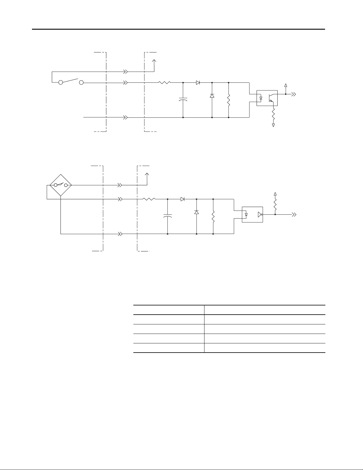
Chapter 4 Connector Data and Feature Descriptions
CTRL_INPUT
REG_INPUT
Figure 29 - Enable, Home, and Overtravel Digital Input Circuits
I/O SUPPLY
INPUT
IO_COM
Customer-supplied Input Device
I/O SUPPLY
INPUT
IO_COM
Customer-supplied Registration
Input Device
(1)
IOD-1, -4, -7, -10
(2)
IOD-2, -5, -8, -11
IOD-3, -6, -9, -12
IOD-13, -16
IOD-14, -17
IOD-15, -18
24V DC
3k Ω
μ
F
0.1
511 Ω
Kinetix 6000
IAM/AM Module
(1) 24V DC source (range) = 21.6V - 26.4V (supplied by drive, not to exceed 250 mA total).
(2) Maximum current input = 10 mA.
Figure 30 - Registration Digital Input Circuits
+24V DC
3k Ω
511 Ω
HCPL-0631
Kinetix 6000
IAM/AM Module
0.001
μ
F
VCC
1k Ω
VCC
1k Ω
Sercos Communication Specifications
The Rx and Tx Sercos connectors are provided on the Kinetix 6000 IAM and
AM module for communication with the Logix5000 controller.
Attribute Value
Data rates 4 and 8 Mbps, selectable via DIP switch
Light intensity Low power or high power, selectable via DIP switch
Cyclic update period 500 μs, min
Node addresses 01…99
(1) The Kinetix 6000M IDM system supports only 8 Mbps and is hardwired for this setting.
(2) Node address assignments begin with the IAM module. Node addresses for additional axes on the same power rail are assigned
by incrementing from left to right (starting with the IAM module address).
Each IDM unit has it’s own node address switches and can be set to any valid address. However, node addresses for the IAM and
AM modules on the power rail and for IDM units must be unique.
(2)
(1)
68 Rockwell Automation Publication 2094-UM001J-EN-P - March 2017
Page 69
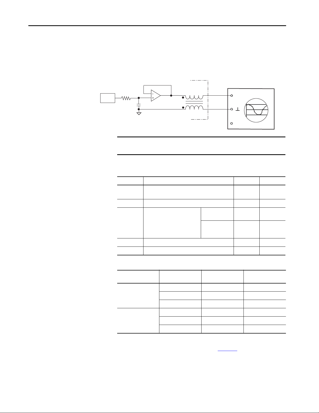
Connector Data and Feature Descriptions Chapter 4
CH1CH1
CH2CH2
DAC
OscilloscopeKinetix 6000 IAM/AM
Module
(second channel not shown)
Analog Outputs
The IAM and AM modules include two analog outputs (IOD-23 and
IOD-25) that you can configure through software to represent drive variables.
Figure 31 - Analog Output Circuit
IMPORTANT Output values can vary during powerup until the specified power supply
voltage is reached.
Table 39 - Analog Output Specifications
Parameter Description Min Max
Resolution
Output current Current capability of the output. 0 +2 mA
Output signal
range
Offset error Deviation when the output is expected to be at 0V. – 1 mV
Bandwidth Frequency response of the analog output DC 7.2k Hz (3 db)
Number of states that the output signal is divided into,
(to the number of bits)
which is 2
Range of the output voltage.
.
2094-xCxx-Mxx and
2094-xMxx drives
2094-xCxx-Mxx-S
and 2094-xMxx-S
drives
– ±11 bits
0+5V
0 +10V
Table 40 - Linear Scaling Specifications
Drive Cat. No.
2094-xCxx-Mxx
or 2094-xMxx
2094-xCxx-Mxx-S
or 2094-xMxx-S
Speed
rpm
10,000 5.0 1000
02.50
-10,000 0 -1000
10,000 10.0 1000
05.00
-10,000 0 -1000
Value
V DC
Tor que
%
For configuration/set up of the analog outputs, refer to Configure Drive
Parameters and System Variables beginning on page 162
Rockwell Automation Publication 2094-UM001J-EN-P - March 2017 69
.
Page 70

Chapter 4 Connector Data and Feature Descriptions
Normally
Open
Relay
Kinetix 6000
IAM Module
Contactor Enable Relay
Contactor enable is a relay-driven contact used in the three-phase powerenable control string to protect the drive electronics during certain fault
conditions. It is capable of handling 120V AC or 24V DC at 1 A or less.
Contactor enable is a function of the converter and is not available in the axis
modules. An active state indicates the drive is operational and does not have a
fault.
ATT EN TI ON : Wiring the contactor enable relay is required. To avoid personal
injury or damage to the drive, wire the contactor enable relay into your
three-phase power-enable control string so that:
• three-phase power is removed from the drive in the event of shutdown
fault conditions.
• drive operation is prevented when the power rail is not fully populated.
• control power is applied to the drive prior to three-phase power.
Refer to IAM Module (without LIM module) on page 192
example.
for a wiring
IMPORTANT All power rail slots must have a module installed or the contactor enable
relay does not close.
Figure 32 - Contactor Enable Relay Circuit
CONT EN+
CONT EN-
Table 41 - Contactor Enable Relay Output Specifications
Attribute Value Min Max
On-state
current
On-state
resistance
Off-state
voltage
Current flow when the relay is closed – 1 A
Contact resistance when the relay is closed – 1 Ω
Voltage across the contacts when the relay is open – 120V AC or 24V DC
70 Rockwell Automation Publication 2094-UM001J-EN-P - March 2017
Page 71
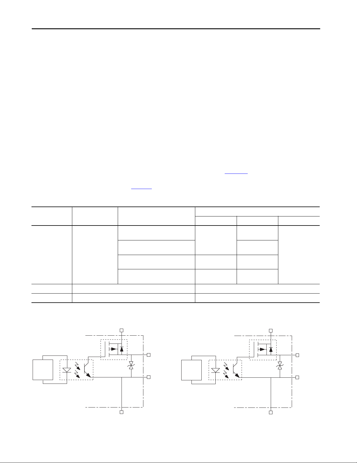
Connector Data and Feature Descriptions Chapter 4
24V PWR (BC-3)
FQB22P10
MBRK+ (BC-5)
MBRK– (BC-6)
(1)
DBRK+ (BC-1)
DBRK– (BC-2)
24V COM (BC-4)
24V PWR (BC-3)
FQB22P10
(1)
24V COM (BC-4)
Resistive Brake Module Circuitry
Kinetix 6000
IAM/AM Module
Motor Brake Circuitry
Kinetix 6000
IAM/AM Module
Control
Board
Control
Board
Power and Relay
Specifications
This section provides a description of the Kinetix 6000 brake relay (BC), input
power (IPD), motor power (MP), and control power (CPD) connectors.
Motor/Resistive Brake Relay
The brake option is a spring-set holding brake that releases when voltage is
applied to the brake coil in the motor. The customer-supplied 24V power
supply drives the brake output through a solid-state relay (series C) and
mechanical relays (series A and B). The solid-state brake driver circuit provides
the following:
• Brake current-overload protection
• Brake over-voltage protection
Two connections are required for the (customer-supplied) motor/resistive
brake input power (BC-3 and BC-4) and two connections each for the motor
and resistive brake output, as shown in Figure 33
series releases. Connections are rated for +24V and current as shown in
Ta b l e 4 2
Table 42 - Brake Relay Output Specifications
Attribute Description IAM/AM Module
2094-AC05-Mxx,-x 2094-AC09-M02-x,
2094-AMP5-x, 2094-AM01-x, 2094-AM02-x
2094-BC01-Mxx-x, 2094-BC02-M02-x,
Current flow when the
On-state current
On-state resistance Contact resistance when the relay is closed 1 Ω
Off-state voltage Voltage across the contac ts when the relay is open 30V
(1) For motors requiring more than the maximum current specified, a relay must be added.
(1)
relay is closed
2094-BMP5-x, 2094-BM01-x, 2094-BM02-x
2094-AC16-M03-x, 2094-AC32-M05-x,
2094-AM03-x, 2094-AM05-x
2094-BC04-M03-x, 2094-BC07-M05-x,
2094-BM03-x, 2094-BM05-x
.
. Wiring is consistent with all
Brake Current Value, max
Series A Series B Series C
N/A
1.0 A
3.0 A
3.0 A
1.3 A N/A
3.0 A 3.0 A
Figure 33 - Brake Relay Circuit (series C)
(1) Noise suppression device.
Rockwell Automation Publication 2094-UM001J-EN-P - March 2017 71
Page 72

Chapter 4 Connector Data and Feature Descriptions
IMPORTANT Motor parking-brake switching frequency must not exceed
10 cycles/min.
Control of the relay to release the motor brake (BC-5 and BC-6) is
configurable in the Logix Designer application (refer to Configure Axis
Properties on page 151
). An active signal releases the motor brake. Turn-on
and turn-off delays are specified by the BrakeEngageDelayTime and
BrakeReleaseDelayTime settings. Refer to Controlling a Brake Example on
page 213
for brake coil currents.
IMPORTANT Holding brakes that are available on Allen-Bradley rotary motors are
designed to hold a motor shaft at 0 rpm for up to the rated brakeholding torque, not to stop the rotation of the motor shaft, or be used as
a safety device.
You must command the servo drive to 0 rpm and engage the brake only
after verifying that the motor shaft is at 0 rpm.
The resistive brake relay (BC-1 and BC-2) controls the resistive brake module
(RBM) contactor. The RBM module is wired between the drive and motor by
using an internal contactor to switch the motor between the drive and a
resistive load. The RBM module contact delay is the time it takes to fully close
the contactor across the motor power input lines, and must be configured in
the software. Refer to RBM Module Interconnect Diagrams beginning on
page 269
for wiring examples.
These steps provide one method you can use to control a brake.
1. Wire the mechanical brake according to the appropriate interconnect
diagram in Appendix A beginning on page 187
.
2. Enter the BrakeEngageDelay and BrakeReleaseDelay times in the Logix
Designer application.
Refer to Axis Properties>Parameter List. The delay times must be from
the appropriate motor family brake specifications table in the Kinetix
Rotary Motion Specifications Technical Data, publication KNX-
TD001.
3. Use the motion instruction Motion Axis Stop (MAS) to decelerate the
servo motor to 0 rpm.
4. Use the motion instruction Motion Servo Off (MSF) to engage the
brake and disable drive.
72 Rockwell Automation Publication 2094-UM001J-EN-P - March 2017
Page 73

Connector Data and Feature Descriptions Chapter 4
Input Power Cycle Capability
The power cycle capability is inversely proportional to the system capacitance
(including DC bus follower), but cannot exceed 2 contactor cycles per minute
with up to 4 axes or 1 contactor cycle per minute with 5…8 axes.
The cycle capability also depends on the converter power rating and the total
system capacitance. Refer to Appendix C on page 227
capacitance.
Table 43 - Maximum Input Power Cycling Specifications (230V)
Attribute 2094-AC05-MP5-S 2094-AC05-M01-S 2094-AC09-M02-S 2094-AC16-M03-S 2094-AC32-M05-S
Main AC input power cycling
(cycles per minute for 10,000 μf) 0.69 4.30
Table 44 - Maximum Input Power Cycling Specifications (460V)
Attribute 2094-BC01-MP5-S 2094-BC01-M01-S 2094-BC02-M02-S 2094-BC04-M03-S 2094-BC07-M05-S
Main AC input power cycling
(cycles per minute for 10,000 μf) 0.12 0.52 2.15 4.30
to calculate total system
For example, in a 4 axis system with a 2094-BC02-M02-S IAM module and
2,000 µF total capacitance, the calculated capability is 0.52 x 10,000/2000 =
2.6 cycles per minute. However, this value is reduced to 2.0 by the 4 axes per
system limitation.
Rockwell Automation Publication 2094-UM001J-EN-P - March 2017 73
Page 74

Chapter 4 Connector Data and Feature Descriptions
Peak Enhancement Specifications
Drives that support the Peak-enhanced mode have the capability of increasing
the maximum inverter peak current to achieve greater overload performance.
IMPORTANT The peak enhancement feature requires the use of RSLogix 5000® software or
the Logix Designer application, and drive firmware as specified in Tab le 4 5
Table 45 - Peak Enhancement Software and Firmware Requirements
.
IAM Module
Cat. No.
2094-BC01-MP5-S 2094-BMP5-S 16 or later 1.111 or later
2094-BC01-M01-S 2094-BM01-S 16 or later 1.111 or later
2094-BC02-M02-S 2094-BM02-S 16 or later 1.111 or later
2094-BC04-M03-S 2094-BM03-S 17 or later 1.117 or later
2094-BC07-M05-S 2094-BM05-S 17 or later 1.117 or later
AM Module
Cat. No.
RSLogix 5000 Software
Versi on
Kinetix 6000 Drive
Firmware Revision
Table 46 - Kinetix 6000 Inverter Peak Overload Support
Kinetix 6000 Drives
Cat. No.
2094-BCxx-Mxx IAM
2094-BMxx AM
2094-BCxx-Mxx-S IAM
2094-BMxx-S AM
(1) Standard mode is enabled by default to preserve backward compatibility, but you can enable the Peak-enhanced mode to achieve
increased peak current performance.
Module
Safe Torqueoff Drive
Non Safe
Tor qu e - of f
Safe
Tor qu e - of f
Series A Series B and C
Standard N/A
Standard
Standard or
Peak Enhanced
(1)
Table 47 - Kinetix 6000 Peak Current Ratings
IAM/AM Module
Cat. No.
2094-BC01-MP5-S 150% 250% 200% 250%
2094-BC01-M01-S 150% 250% 200% 250%
2094-BC02-M02-S 150% 250% 200% 250%
2094-BC04-M03-S 150% 250% 200% 250%
2094-BC07-M05-S 150% 200% 200% 300%
2094-BMP5-S 150% 250% N/A N/A
2094-BM01-S 150% 250% N/A N/A
2094-BM02-S 150% 250% N/A N/A
2094-BM03-S 150% 250% N/A N/A
2094-BM05-S 150% 200% N/A N/A
Peak Inverter Current Rating Peak Converter Current Rating
Standard Peak Enhanced Series A Series B and C
74 Rockwell Automation Publication 2094-UM001J-EN-P - March 2017
Page 75

Figure 34 - Load Duty-cycle Profile Example
D =
T
T
PK
x 100%
I
Cont
I
Base
I
PK
T
PK
T
D =
T
T
PK
x 100%
Table 48 - Peak Duty Cycle Definition of Terms
Term Definition
Continuous Current Rating (I
Peak Curre nt Rati ng (I
) The maximum value of current that can be output continuously.
Cont
PKmax
)
The maximum value of peak current that the drive can output. This rating is
valid only for overload times less than T
The ratio of time at peak to the Application Period and is defined as:
Duty Cycle (D)
(1)
Connector Data and Feature Descriptions Chapter 4
.
PKmax
Time at Peak (T
Peak Curre nt (I
)
PK
)
PK
The time at peak current (IPK) for a given loading profile. Must be less than
or equal to T
The level of peak current for a given loading profile. I
equal to the Peak Current Rating (T
PKmax
.
must be less than or
PK
of the drive.
PKMAX)
The level of current between the pulses of peak current for a given loading
Base Current (I
Loading Profile
Base
)
profile. I
(I
The loading profile is comprised of I
completely specify the operation of the drive in an overload situation. These
must be less than or equal to the continuous current rating
Base
of the drive.
Cont)
, I
, TPK, and D (or T) values and
PK
Base
values are collectively defined as the Loading Profile of the drive.
Application Period (T) The sum of the times at I
(1) All current values are specified as RMS.
(TPK) and I
PK
Base
.
Rockwell Automation Publication 2094-UM001J-EN-P - March 2017 75
Page 76

Chapter 4 Connector Data and Feature Descriptions
Applies to these Kinetix 6000 drives:
2094-BC01-MP5-S, 2094-BMP5-S,
2094-BC01-M01-S, 2094-BM01-S,
2094-BC02-M02-S, 2094-BM02-S,
2094-BC04-M03-S, 2094-BM03-S
Applies to these Kinetix 6000 drives:
2094-BC07-M05-S, 2094-BM05-S
50%
45%
40%
Figure 35 - Peak Inverter Overload (TPK < 2.0 s)
35%
max
30%
25%
20%
15%
Maximum Duty Cycle (D )
10%
5%
0%
50%
45%
40%
0%
40%
% Base Current (I /I )
(1) Base current (I
60%
Cont
Base
) and peak current (IPK) are a percentage of the continuous drive current rating (I
Base
80%20%
Figure 36 - Peak Inverter Overload (TPK < 2.0 s)
100%
Legend
(1)
I = 150%
PK
I = 200%
PK
I = 250%
PK
).
Cont
35%
max
30%
25%
20%
15%
Maximum Duty Cycle (D )
10%
5%
0%
0%
40%
% Base Current (I /I )
(1) Base current (I
60%
Cont
Base
) and peak current (IPK) are a percentage of the continuous drive current rating (I
Base
80%20%
76 Rockwell Automation Publication 2094-UM001J-EN-P - March 2017
100%
Legend
(1)
I = 150%
PK
I = 200%
PK
).
Cont
Page 77
Connector Data and Feature Descriptions Chapter 4
Control Power
The IAM module requires AC input power for logic circuitry.
IMPORTANT The control power input requires an AC (EMC) line filter for CE certification.
For filter examples, refer to Agency Compliance on page 22
IMPORTANT 2094-BCxx-Mxx-x (460V) IAM modules require a step down transformer for
single-phase control power input. Source the 2094-ACxx-Mxx-x (230V) IAM
module control power from the three-phase input power (line-to-line) with
neither leg bonded to ground or neutral potential. The National Electrical
Code and local electrical codes take precedence over the values and
methods provided. Implementation of these codes is the responsibility of
the machine builder.
Table 49 - Control Power Input Power Specifications
Attribute Value
Input voltage 95…264V AC rms, single-phase
Input power frequency 47…63 Hz
Control power AC input current
Nom @ 220/230V AC rms
Nom @ 110/115V AC rms
Max inrush (0-pk)
(1) For eight axis systems with 230V AC control input voltage and 50 °C (122°F) ambient temperature the maximum inrush duration
is less than 1/2 line cycle. Use this equation to calculate maximum inrush current for systems with different axis count and
control input voltage.
= 0.043 x (VIN) + 6.72 x (# of axes) + 0.000333 x (V
I
PK
6 A
6 A
(1)
98 A
2
) - 0.816 x (# of axes)2 + 0.0358 x (# of axes x VIN)
IN
.
Table 50 - Control Power Current Requirements
110/115V AC Input 220/230V AC Input
Modules on Power Rail
IAM module only 0.56 67 0.36 85
IAM and 1 AM module 0.99 119 0.64 153
IAM and 2 AM module 1.43 172 0.92 220
IAM and 3 AM module 1.87 224 1.20 287
IAM and 4 AM module 2.31 277 1.48 354
IAM and 5 AM module 2.74 329 1.75 421
IAM and 6 AM module 3.18 382 2.03 488
IAM and 7 AM module 3.62 434 2.31 555
IDM power interface
module (IPIM)
Input CurrentAInput VA
VA
For specifications and an example for calculating the IPIM module current
requirements, refer to the Kinetix 6000M Integrated Drive-Motor User Manual,
publication 2094-UM003
.
Input CurrentAInput VA
VA
For Kinetix 6000M systems, calculate the sum of the control power current
requirements for each IPIM module on the power rail and add that value with
the appropriate value from Ta b l e 5 0
for the number of axes on the power rail.
Rockwell Automation Publication 2094-UM001J-EN-P - March 2017 77
Page 78
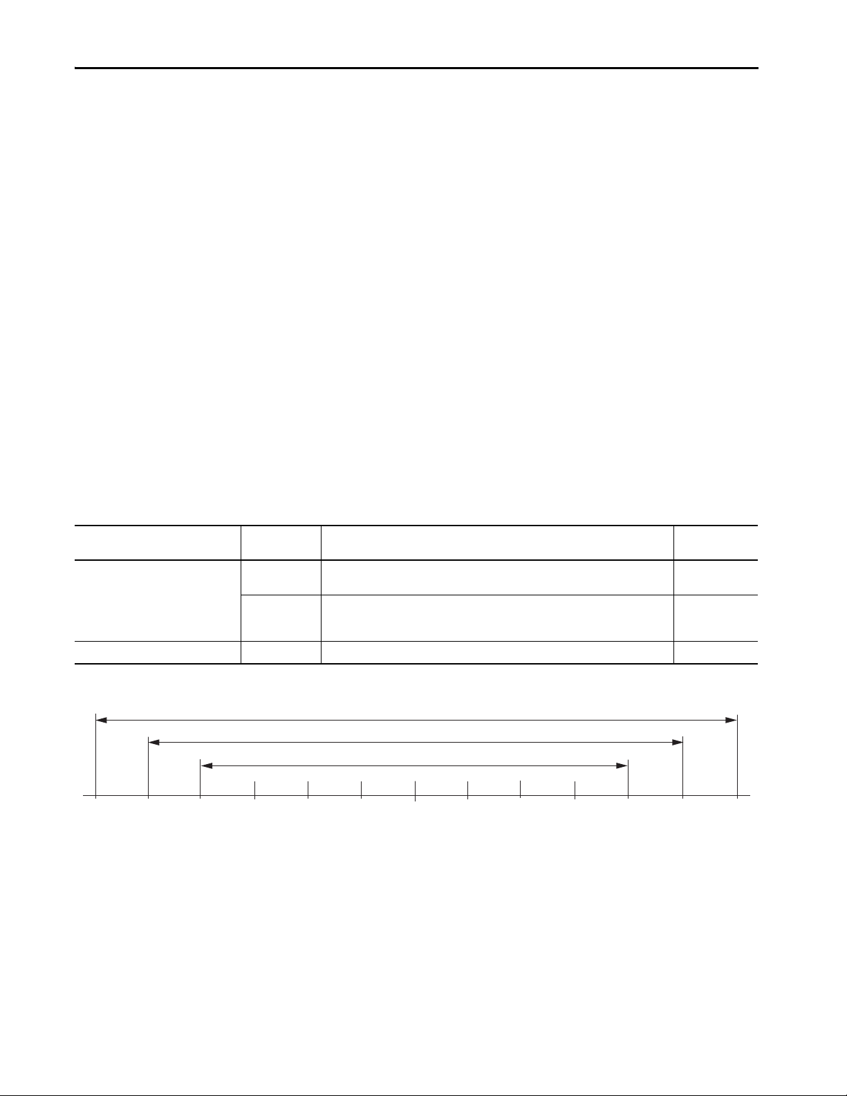
Chapter 4 Connector Data and Feature Descriptions
+2048-2048 +1024-1024
+64
-64
+256-256
+512
-512
0
-128
+128
Position at Power Down
4096 Turns
2048 Turns
1024 Turns
Feedback Specifications
The IAM and AM modules can accept motor and auxiliary feedback signals
from these types of encoders:
•Stegmann Hiperface
• TTL or Sine/Cosine with index pulse and Hall commutation
• Resolver Transmitter TR = 0.25 (motor feedback only)
Motor feedback from Heidenhain EnDat high-resolution encoders is also
accepted, but only when using drive firmware revision 1.116 or later and the
2090-K6CK-KENDAT low-profile feedback module for EnDat to Hiperface
conversion.
TIP Auto-configuration in the Logix Designer application of intelligent absolute, high-
resolution, incremental, and EnDat encoders is possible only with Allen-Bradley
motors.
Absolute Position Feature
The drive’s absolute position feature tracks the position of the motor, within
the multi-turn retention limits, while the drive is powered off. The absolute
position feature is available with only these multi-turn encoders.
Table 51 - Absolute Position Designator Examples
Encoder Type
Stegmann Hiperface
Heidenhain EnDat -7 RDB-Bxxxxxx-7 4096 (±2048)
Cat. No.
Designator
-M
-V
Motor/Actuator Cat. No.
MPL-A/Bxxxxx-M, MPM-A/Bxxxxx-M, MPF-A/Bxxxxx-M, MPS-A/Bxxxxx-M,
MPAR-A/B3xxxx-M, MPAI-A/BxxxxxM
MPL-A/Bxxxxx-V,
MPAS-A/Bxxxx1-V05, A/MPAS-Bxxxx2-V20,
MPAR-A/B1xxxx-V, MPAR-A/B2xxxx-V, MPAI-A/BxxxxxV
Retention Limits
(turns)
4096 (±2048)
4096 (±2048)
Figure 37 - Absolute Position Limits (measured in turns)
78 Rockwell Automation Publication 2094-UM001J-EN-P - March 2017
Page 79
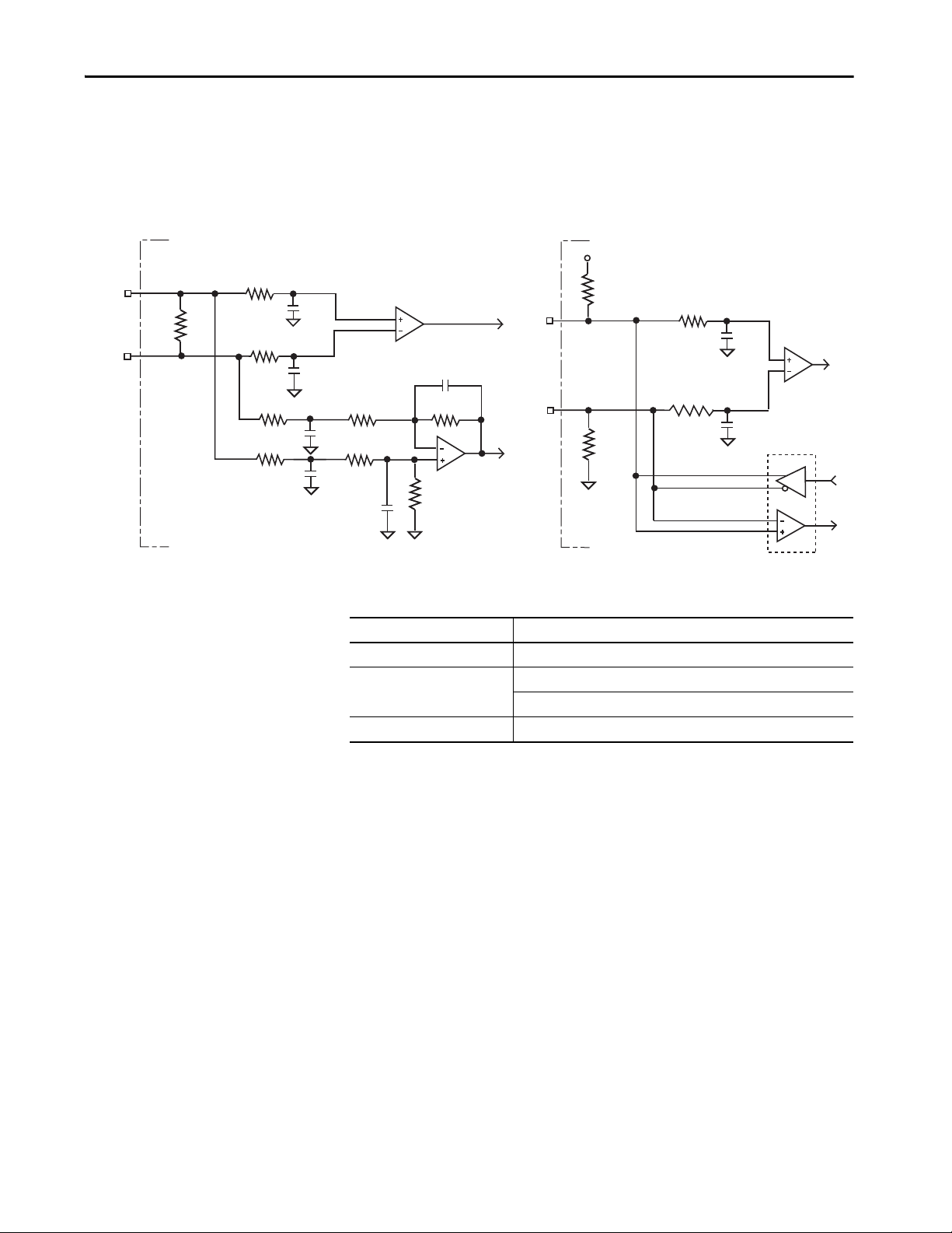
Connector Data and Feature Descriptions Chapter 4
10k Ω
10k Ω
+5 V
1k Ω
1k Ω
+
-
56 pF
56 pF
10k Ω
1k Ω
1k Ω
10k Ω
1k Ω
1k Ω
1k Ω
1k Ω
1k Ω
100 pF
+
-
100 pF
56 pF
56 pF
56 pF
56 pF
Drive
Drive
AM and BM Channel Inputs
IM Channel Input
Motor Feedback Specifications
AM, BM, and IM input encoder signals are filtered by using analog and digital
filtering. The inputs also include illegal state change detection.
Figure 38 - AM, BM, and IM Motor Encoder Input Circuits
Table 52 - Motor Encoder Feedback Specifications
Attribute Value
Encoder types Incremental, A quad B, sine/cosine, intelligent, resolver, and absolute
Maximum input frequency
Commutation feedback Hall sensor
500 kHz (TTL input) per channel
250 kHz (sine/cosine input)
Rockwell Automation Publication 2094-UM001J-EN-P - March 2017 79
Page 80

Chapter 4 Connector Data and Feature Descriptions
Parameter Description Min Max
AM, BM, and IM
On-state input voltage
AM, BM, and IM
Off-state input voltage
Common mode
input voltage
DC current draw Current draw into the + or - input. -30 mA 30 mA
AM, BM input
signal frequency
IM pulse width
AM, BM phase error
250 KHz line frequenc y
AM, BM phase error
100 KHz line frequenc y
Table 53 - AM, BM, and IM Input Specifications for TTL Encoders
Input voltage difference between the plus (+) input and the
minus (-) input that is detected as an on-state.
Input voltage difference between the plus (+) input and the
minus (-) input that is detected as an off-state.
Potential difference between any encoder signal and logic
ground.
Frequency of the AM or BM signal inputs. The count frequency is
4 times this frequency, because the circuitry counts all four
transitions.
Pulse width of the index input signal. Because the index is active
for a percentage of a revolution, the speed determines the pulse
width.
Amount that the phase relationship between the AM and BM
inputs can deviate from the nominal 90°.
Amount that the phase relationship between the AM and BM
inputs can deviate from the nominal 90°.
+1.0V +7.0V
-1.0V -7.0V
-7.0V +12.0V
–500 kHz
125 nS –
-22.5° +22.5°
-45° +45°
Table 54 - AM, BM, and IM Input Specifications for Sine/Cosine Encoders
Parameter Description Min Max
Sine/cosine
input signal
frequency
Sine/cosine
input voltage
Frequency of the Sine or Cosine s ignal inputs. – 250 kHz
Peak-to-peak input voltages of the Sine or Cosine inputs. 0.8V (p-p) 1.2V (p-p)
Table 55 - Specifications for Heidenhain EnDat Encoders
Command Set
EnDat 2.2 EnDat 01 1V p-p Sin/Cos, <2 MHz clock frequency
Order
Designation
Description
Feedback Power Supply Specifications
The IAM and AM power circuit board generates +5V and +9V DC for motor
and auxiliary feedback power. Short circuit protection and separate common
mode filtering for each channel is included.
Supply Reference
+5V DC EPWR_5V 4.9 5.25 5.4 0 400
+9V DC EPWR_9V 8.3 9.1 9.9 0 275
Voltage Current mA
Min Nominal Max Min Max
80 Rockwell Automation Publication 2094-UM001J-EN-P - March 2017
Page 81

Connector Data and Feature Descriptions Chapter 4
Auxiliary Position Feedback Encoders
Allen-Bradley Bulletin 842HR, 844D, 847H, and 847T encoders are the
preferred encoders for auxiliary feedback connections.
Table 56 - Allen-Bradley Auxiliary Feedback Encoders
Cat. No. Description
842HR-MJDZ115FWYD (multi-turn)
842HR-SJDZ115FWYD (single-turn)
844D-B5CC1FW
844D-B5CC1CS
844D-B5CC1DR
847H-DN1A-RH01024
847H-DN1A-RH02048
847H-DN1A-RH05000
847T-DN1A-RH01024 Size 20, incremental encoder, standard square flange , 3/8 inch
847T-DN1A-RH02048
Size 25, sine/cosine (serial), square flange, 3/8 in. solid shaft with
flat, 5…12V DC, digital RS-485 interface, M23, 17-pin connector
HS35, hollow-shaft incremental encoders, rear (through-shaft),
5/8 inch, tether, 3/8 in. bolt on a 2.5…4.0 in. diameter, 10-pin
connector, 5V DC in, 5V DC DLD out
Size 25, incremental encoder, standard square flange , 3/8 inch
diameter shaft with flat, 4.5…5.5V line driver, TTL (B-Leads-A,
CW, Z gated with BN), MS connector, 10-pin
diameter shaft with flat, 4.5…5.5V line driver, TTL (B-Leads-A,
CW, Z gated with BN), MS connector, 10-pin
Refer to the Kinetix Motion Accessories Technical Data, publication
KNX-TD004
, for more information on these Allen-Bradley encoders.
Rockwell Automation Publication 2094-UM001J-EN-P - March 2017 81
Page 82

Chapter 4 Connector Data and Feature Descriptions
Notes:
82 Rockwell Automation Publication 2094-UM001J-EN-P - March 2017
Page 83

Chapter 5
Connect the Kinetix 6000 Drive System
This chapter provides procedures for wiring your Kinetix® 6000 drive system
components and making cable connections.
Top ic Pa ge
Basic Wiring Requirements 83
Determine the Input Power Configuration 85
Set the Ground Jumper in Select Power Configurations 89
Grounding the Kinetix 6000 Drive System 95
Power Wiring Requirements 97
Power Wiring Guidelines 99
Wiring the IAM/AM Module Connectors 100
Apply the Motor Cable Shield Clamp 116
Feedback and I/O Cable Connections 117
Wiring the Feedback and I/O Connectors 122
External Shunt Module Connections 127
IPIM Module Connections 128
RBM Module Connections 129
Sercos Fiber-optic Cable Connections 130
Kinetix 6000M Integrated Drive-Motor Sercos Connections 133
Ethernet Cable Connections 134
Basic Wiring Requirements
This section contains basic wiring information for the Kinetix 6000 drive
modules.
ATT EN TI ON : Plan the installation of your system so that you can perform all
cutting, drilling, tapping, and welding with the system removed from the
enclosure. Because the system is of the open type construction, be careful to
keep any metal debris from falling into it. Metal debris or other foreign
matter can become lodged in the circuitry, which can result in damage to
components.
SHOCK HAZARD: To avoid hazard of electrical shock, perform all mounting
and wiring of the Bulletin 2094 power rail and drive modules prior to
applying power. Once power is applied, connector terminals can have
voltage present even when not in use.
Rockwell Automation Publication 2094-UM001J-EN-P - March 2017 83
Page 84

Chapter 5 Connect the Kinetix 6000 Drive System
IMPORTANT This section contains common PWM servo system wiring configurations,
size, and practices that can be used in a majority of applications. National
Electrical Code, local electrical codes, special operating temperatures, duty
cycles, or system configurations take precedence over the values and
methods provided.
Building Your Own Cables
IMPORTANT Factory-made cables are designed to minimize EMI and are recommended
over hand-built cables to optimize system performance.
Building your own cables is not an option for the hybrid and network cables
used in Kinetix 6000M integrated drive-motor systems.
Follow these guidelines when building cables for compatible motors and
actuators:
• Connect the cable shield to the connector shells on both ends of the
cable with a complete 360° connection.
• Use twisted pair cable whenever possible. Twist differential signals with
each other and twist single-ended signals with the appropriate ground
return.
Refer to the Kinetix Motion Accessories Technical Data, publication
KNX-TD004
and motor-end connector kit catalog numbers.
, for low-profile connector kit, drive-end (mating) connector kit,
Routing the Power and Signal Cables
Be aware that when you route power and signal wiring on a machine or system,
radiated noise from nearby relays, transformers, and other electronic drives can
be induced into motor or encoder feedback signals, input/output
communication, or other sensitive low voltage signals. This can cause system
faults and communication anomalies.
Refer to Electrical Noise Reduction on page 34
and low voltage cables in wireways. Refer to the System Design for Control of
Electrical Noise Reference Manual, publication GMC-RM001
information.
for examples of routing high
, for more
84 Rockwell Automation Publication 2094-UM001J-EN-P - March 2017
Page 85
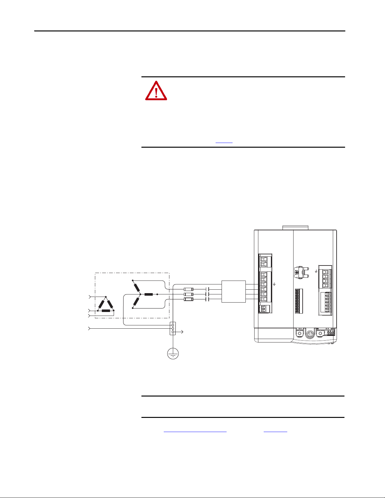
Connect the Kinetix 6000 Drive System Chapter 5
Transformer
Kinetix 6000 IAM Module,
Top Vie w
Three- phase
Input VAC
Phase Ground
Transformer (WYE) Secondary
Bonded Cabinet
Ground
Ground Grid or
Power Distribution Ground
Connect to power rail
ground stud.
Three-phas e
AC Lin e Filter
M1
Contac tor
Circuit
Protection
Determine the Input Power
Configuration
Before wiring input power to your Kinetix 6000 system, you must determine
the type of input power you are connecting to. The IAM module is designed to
operate in both grounded and ungrounded environments.
ATT EN TI ON : When you are using a LIM module for input power, the VAC
LINE input power must come from a grounded configuration. When you are
not using a LIM module for input power, ungrounded, corner-grounded, and
impedance-grounded power configurations are permitted, but you must set
the ground jumper to the ungrounded position for proper drive operation. In
addition, set the ground jumper when an active converter supplies the
DC-bus voltage. Refer to Set the Ground Jumper in Select Power
Configurations on page 89
for more information.
Grounded Power Configurations
The grounded (WYE) power configuration lets you ground your three-phase
power at a neutral point. This type of grounded power configuration is
preferred.
Figure 39 - Grounded Power Configuration (WYE Secondary)
1 2
CTRL 2
CTRL 1
1 2 3 4 5 6
L3
L2
L1
DC-
DC+
L3
L2
L1
1 2
CONT EN-
CONT EN+
1 2 3 4 5 6 7 8 9
MBRK -
MBRK +
COM
PWR
DBRK -
DBRK +
RX
DPI
W
V
U
1 2 3 4
1 2 3 4 5 6
TX
BAUD
RATE
The IAM module has a factory-installed ground jumper for grounded power
distribution.
IMPORTANT If you determine that you have grounded power distribution in your facility,
you do not need to move the ground jumper.
Refer to Power Wiring Examples
interconnect diagrams with and without the LIM module.
beginning on page 189 for input power
Rockwell Automation Publication 2094-UM001J-EN-P - March 2017 85
Page 86
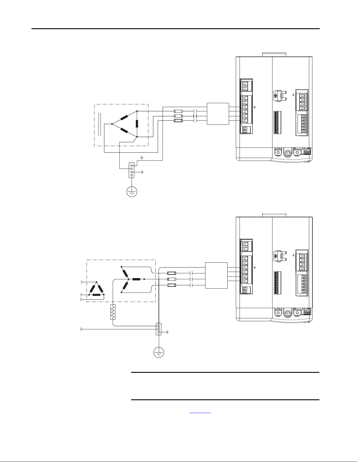
Chapter 5 Connect the Kinetix 6000 Drive System
L3
L1
L2
DC-
DC+
L3
L2
L1
CONT EN-
CONT EN+
W
V
U
MBRK -
MBRK +
COM
PWR
DBRK -
DBRK +
CTRL 2
CTRL 1
1 2 3 4
1 2 3 4 5 6
1 2
1 2 3 4 5 6
1 2
BAUD
RATE
TX
RX
DPI
1 2 3 4 5 6 7 8 9
Transformer (Delta) Secondary
Bonded Cabinet
Ground
Transformer
Ground Grid or
Power Distribution G round
Kinetix 6000 IAM Module,
Top Vie w
Connect to power rail ground stud.
Three-phas e
AC Lin e Filter
M1
Contac tor
Circuit
Protection
L3
L2
L1
DC-
DC+
L3
L2
L1
CONT EN-
CONT EN+
W
V
U
MBRK -
MBRK +
COM
PWR
DBRK -
DBRK +
CTRL 2
CTRL 1
1 2 3 4
1 2 3 4 5 6
1 2
1 2 3 4 5 6
1 2
BAUD
RATE
TX
RX
DPI
1 2 3 4 5 6 7 8 9
Transformer
Three-phase
Input VAC
Phase Ground
Transformer (WYE) Secondary
Ground Grid or
Power Distribution Ground
Three-phase
AC Line Fi lter
Circuit
Protection
M1
Contactor
Bonded Cabinet Ground
Kinetix 6000 IAM Module,
Top Vie w
Connect to power rail ground stud.
Figure 40 - Corner-grounded Power Configuration (Delta Secondary)
Figure 41 - Impedance-grounded Power Configuration (WYE Secondary)
IMPORTANT Even though impedance-grounded and corner-grounded power
configurations have a ground connection, treat them as ungrounded when
installing Kinetix 6000 drive systems.
Refer to Appendix A on page 187, for input-power interconnect diagrams with
and without the LIM module.
86 Rockwell Automation Publication 2094-UM001J-EN-P - March 2017
Page 87

Connect the Kinetix 6000 Drive System Chapter 5
Transformer
Kinetix 6000 IAM Module,
Top Vie w
Three-phase
Input VAC
Chassis Ground
Bonded Cabinet
Ground
Ground Grid or
Power Distribution Ground
Connect to power rail
ground stud.
Circuit
Protection
M1
Contac tor
Transformer (Delta) Secondary
Ungrounded Power Configurations
The ungrounded power configuration (Figure 42) does not provide a neutral
ground point. Ungrounded, impedance-grounded, and corner-grounded
power configurations are allowed, but you must move a jumper (internal to the
IAM module) across a 120 kΩ resistor. The IAM module ground jumper
(default configuration) is set for grounded power distribution.
IMPORTANT If you determine that you have ungrounded, impedance-grounded, or
corner-grounded power distribution in your facility, you must move the
ground jumper (configured for grounded power) to the ungrounded power
position inside the IAM module.
Refer to Set the Ground Jumper in Select Power Configurations on page 89
for more information.
Figure 42 - Ungrounded Power Configuration
Refer to Appendix A on page 187, for input-power interconnect diagrams with
and without the LIM module.
1 2
CTRL 2
CTRL 1
1 2 3 4 5 6
L3
L2
L1
DC-
DC+
L3
L2
L1
1 2
CONT EN-
CONT EN+
ATT EN TI ON : Ungrounded systems do not reference each phase potential to
a power distribution ground. This can result in an unknown potential to
earth ground.
1 2 3 4 5 6 7 8 9
MBRK -
MBRK +
PWR
DBRK -
DBRK +
RX
DPI
W
V
U
COM
1 2 3 4
1 2 3 4 5 6
TX
BAUD
RATE
Rockwell Automation Publication 2094-UM001J-EN-P - March 2017 87
Page 88

Chapter 5 Connect the Kinetix 6000 Drive System
N.C.
2094-xCxx-Mxx-x
2094-xCxx-Mxx-x
DC Common Bus
Configurations
When the IAM module is used in a DC common-bus configuration, the IAM
module is known as a leader IAM or follower IAM module. The IAM (noncommon bus) and leader IAM module have identical three-phase input power
connections. The leader IAM module is responsible for discharging the DC
bus, and for providing common-bus follower drives with DC bus precharge,
bus regulation, phase-loss detection, and ground fault detection. Follower
IAM modules do not have three-phase input power connections, but have DC
bus connections from a leader IAM module.
Table 57 - IAM Module Terminology and Use
This Module Is Wired And is
IAM With three-phase input power. Not wired in Common-bus mode.
Leader IAM
Follower IAM
With three-phase input power, but has DC common-bus
connections to a follower IAM module.
Without three-phase input power, but has DC common-bus
connections from a leader IAM module.
Wired in Common-bus mode.
Wired in Common-bus mode and configured by
using the Logix Designer application.
IMPORTANT Use Kinetix 6000 drive firmware revision 1.85 and the Logix Designer
Application or RSLogix 5000® software, version 15 or later, for common-bus
power configurations.
The Kinetix 6000 leader IAM module can operate with non-Kinetix 6000
follower drives, as can the Kinetix 6000 follower IAM module operate with
non-Kinetix 6000 common-bus leader drives. However, non-Kinetix 6000
leader and follower drives must meet the same functional requirements as the
Kinetix 6000 leader and follower IAM modules.
Bonded Cabinet
Ground
Three-p hase
Input Power
Kinetix 6000
DC Common Bus
Connections
Common-bus Leader
IAM Module
1 2
CTRL 2
CTRL 1
1 2 3 4 5 6
DC-
DC+
L3
L2
L1
1 2
CONT EN-
CONT EN+
1 2 3 4 5 6 7 8 9
RX
W
V
U
MBRK -
MBRK +
COM
PWR
DBRK -
DBRK +
DPI
IMPORTANT Any non-Kinetix 6000 common-bus leader IAM module that does not
provide precharge is required to add an additional external precharge circuit
before connecting to any Kinetix 6000 common-bus follower IAM module.
Figure 43 - Typical DC Common-bus Configuration
2094-xMxx-x AM Modules or
2094-SEPM-B24-S IPIM Modules
1 2 3 4
TX
1 2 3 4 5 6
BAUD
RATE
1 2 3 4 5 6 7 8 9
RX
W
V
1 2 3 4
U
MBRK -
MBRK +
COM
PWR
DBRK -
1 2 3 4 5 6
DBRK +
TX
BAUD
W
V
1 2 3 4
U
MBRK -
1 2 3 4 5 6 7 8 9
MBRK +
COM
PWR
DBRK -
1 2 3 4 5 6
DBRK +
RX
TX
RATE
BAUD
RATE
N.C.
N.C.
Common-bus Follower
IAM Module
1 2
CTRL 2
CTRL 1
1 2 3 4 5 6
DC-
DC+
L3
L2
L1
1 2
CONT EN-
CONT EN+
1 2 3 4 5 6 7 8 9
RX
DPI
W
V
U
MBRK -
MBRK +
COM
PWR
DBRK -
DBRK +
2094-xMxx-x AM Modules or
2094-SEPM-B24-S IPIM Modules
W
V
1 2 3 4
1 2 3 4
TX
1 2 3 4 5 6
BAUD
U
MBRK -
1 2 3 4 5 6 7 8 9
MBRK +
COM
PWR
DBRK -
1 2 3 4 5 6
DBRK +
RX
TX
BAUD
RATE
RATE
1 2 3 4 5 6 7 8 9
RX
W
V
1 2 3 4
U
MBRK -
MBRK +
COM
PWR
DBRK -
1 2 3 4 5 6
DBRK +
TX
BAUD
RATE
88 Rockwell Automation Publication 2094-UM001J-EN-P - March 2017
Page 89

Connect the Kinetix 6000 Drive System Chapter 5
Common Bus Fusing Requirements
When using a Kinetix 6000 leader IAM module, DC-bus fuses are required
only when wiring to more than one Kinetix 6000 follower IAM module.
When wiring multiple follower IAM modules, terminal blocks are required to
extend the DC common-bus power to additional drives. Install fuses in both
lines of the DC bus between the DC bus terminal block and each follower
IAM module. Base these fuse ratings on the DC input current of each follower
IAM module.
When using a non-Kinetix 6000 common-bus leader drive, DC bus fuses are
required in both lines of the DC bus, between the common-bus leader drive
and follower IAM module. Base these fuse ratings on the common-bus leader
drive DC output current. When using more than one follower IAM module,
install fuses in both lines of the DC bus between the non-Kinetix 6000
common-bus leader and the terminal block as well as between the DCbus
terminal block and each follower IAM module.
Set the Ground Jumper in
Select Power Configurations
Refer to Circuit Breaker/Fuse Options on page 28
breaker/fuse sizes. Refer to DC Common Bus Wiring Examples on page 193
for interconnect diagrams.
Setting the ground jumper is required when using an ungrounded, cornergrounded, and impedance-grounded power configurations. Setting the ground
jumper is also required when the Bulletin 8720MC regenerative power supply
or any active converter provides DC-bus power.
Setting the jumper involves removing the IAM module from the power rail,
opening the IAM module, and moving the jumper.
IMPORTANT If you have grounded power distribution, you do not need to set the ground
jumper. Go to Grounding the Kinetix 6000 Drive System on page 95
ATT EN TI ON : Because the unit no longer maintains line-to-neutral voltage
protection, risk of equipment damage exists when you move the ground
jumper.
Setting the ground jumper is best done when the IAM module is removed from
the power rail and placed face-up on a solid surface equipped as a grounded
static-safe workstation.
, for recommended circuit
.
ATT EN TI ON : This drive contains electrostatic discharge (ESD) sensitive parts
and assemblies. You are required to follow static-control precautions when
you install, test, service, or repair this assembly. If you do not follow ESD
control procedures, components can be damaged. If you are not familiar with
static control procedures, refer to Guarding Against Electrostatic Damage,
publication 8000-4.5.2
Rockwell Automation Publication 2094-UM001J-EN-P - March 2017 89
, or any other applicable ESD awareness handbook.
Page 90

Chapter 5 Connect the Kinetix 6000 Drive System
When using ungrounded input power in common-bus configurations, use this
table to determine where to set the ground jumper.
Table 58 - Ground Jumper to Set
Leader Drive Follower Drive Set the Jumper in This Drive
Kinetix 6000 IAM module Kinetix 6000 IAM module Leader drive
Kinetix 6000 IAM module Non-Kinetix 6000 drive Leader drive
Non-Kinetix 6000 drive Kinetix 6000 IAM module
Follower drive (if no setting exists
in the leader drive)
ATTENTION: Risk of equipment damage exists. The facility ground
configuration must be accurately determined. Do not move the ground
jumper for grounded power configurations (default). Move the ground
jumper for ungrounded, corner-grounded, and impedance-grounded power,
or when an active converter supplies the DC-bus voltage.
Table 59 - Ground Jumper Configurations
Ground Configuration Example Diagram Ground Jumper Configuration Benefits of Correct Configuration
• UL and EMC compliance
Grounded (wye) Figure 39 on page 85
• AC-fed ungrounded
• Corner grounded
• Impedance grounded
DC-bus from active converter Figure 92 on page 196
Figure 42 on page 87
Figure 40 on page 86
Figure 41 on page 86
Grounded power (default setting)
Set for ungrounded power
• Reduced electrical noise
• Most stable operation
• Reduced voltage stress on components and motor
bearings
• Helps avoid severe equipment damage when ground
faults occurs
• Reduced leakage current
Set the Ground Jumper
ATT EN TI ON : To avoid personal injury, the ground jumper access area must
be kept closed when power is applied. If power was present and then
removed, wait at least 5 minutes for the DC-bus voltage to dissipate and
verify that no DC-bus voltage exists before accessing the ground jumper.
Follow these steps to set the ground jumper for ungrounded power.
1. Remove the IAM module from the power rail.
For detailed instructions, refer to Remove Kinetix 6000 Drive Modules
on page 182
2. Remove the top and bottom front-panel screws.
Refer to the figures beginning on page 92
page 93
90 Rockwell Automation Publication 2094-UM001J-EN-P - March 2017
.
(460V IAM module) for an illustration of your actual hardware.
(230V IAM module) or
Page 91

Connect the Kinetix 6000 Drive System Chapter 5
3. Swing the front panel open to the right, as shown, and locate the ground
jumper.
IMPORTANT Do not attempt to remove the front panel from the IAM module. The
front panel status indicators and switches are also connected to the
IAM module with a ribbon cable. The ribbon cable acts like a hinge
and lets you swing the front panel open to access the ground
jumper.
4. Move the ground jumper.
IAM Module (series A)
2094-ACxx-Mxx-x (230V)
2094-BC01-MP5-x (460V)
2094-BC02-M02-x (460V)
2094-BC04-M03-x (460V)
2094-BC07-M05-x (460V)
(1) Applies to series A and C (230V) drives.
IAM Module (series B and C)
2094-BC01-MP5-S (460V)
2094-BC01-M01-S (460V)
2094-BC02-M02-S (460V)
2094-BC04-M03-S (460V)
2094-BC07-M05-S (460V)
(1)
Grounded (default) Ungrounded
P15 and P16 P15 and P17
P13 and P14 P13 and P122094-BC01-M01-x (460V)
P14 and P13 P14 and P12
Grounded (default) Ungrounded
P16 and P17 P18 and P19
Configuration
Configuratio n
5. Replace the IAM module front panel and two screws.
Apply 1.6 N•m (14 lb•in) torque.
6. Mount the IAM module back on the power rail.
For detailed instructions, refer to Replace Kinetix 6000 Drive Modules
on page 183
Rockwell Automation Publication 2094-UM001J-EN-P - March 2017 91
.
Page 92
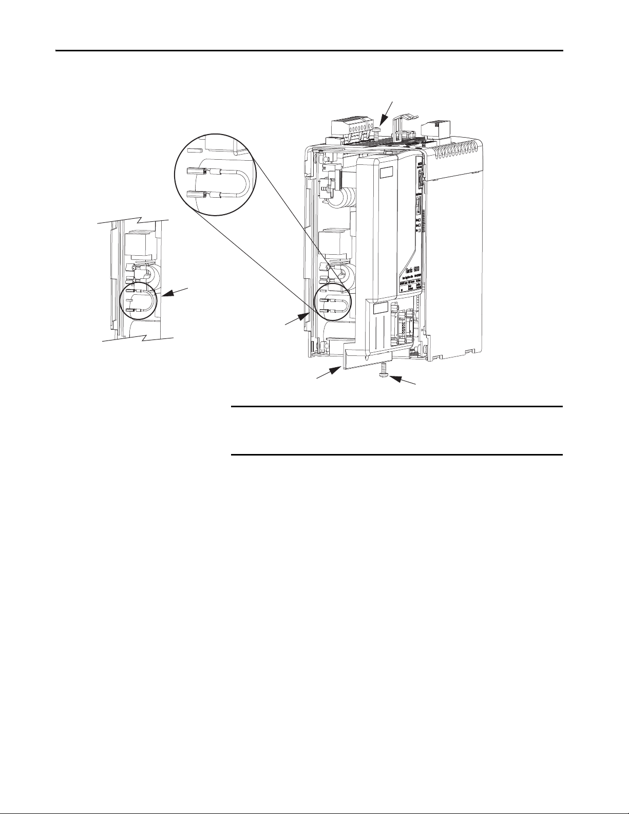
Chapter 5 Connect the Kinetix 6000 Drive System
P17
P16
P15
Top Scre w
2094-ACxx-Mxx-x
IAM Module (230V)
Bottom Screw
Front Panel (opened)
Ground jumper set
for grounded configuration
(default setting).
Ground jumper set
for ungrounded configuration.
Figure 44 - Setting the Ground Jumper (230V Series A and C IAM modules)
IMPORTANT Use the default jumper setting or remove the jumper entirely for grounded
power configurations. Move the jumper, as shown above, for ungrounded
power.
92 Rockwell Automation Publication 2094-UM001J-EN-P - March 2017
Page 93
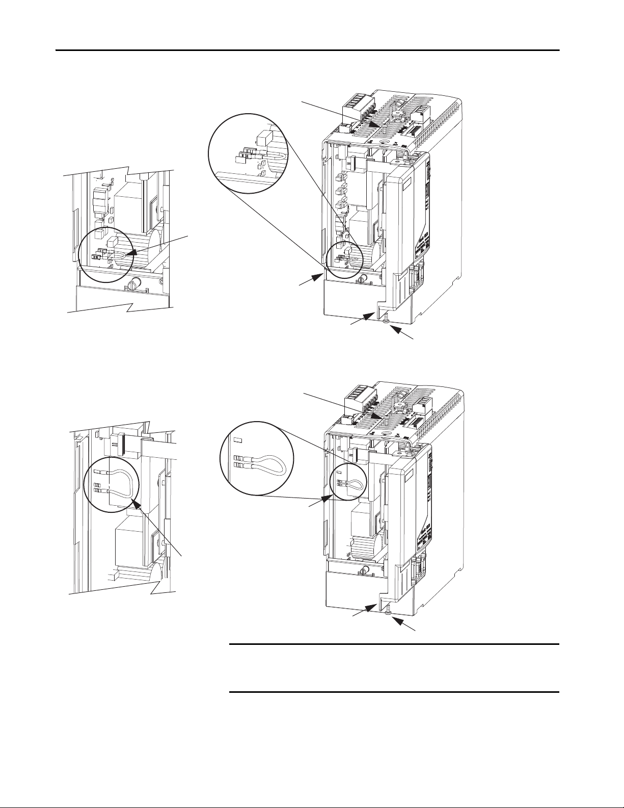
P13
P14
P12
P13
P14
P12
Bottom Screw
Front Panel (opened)
Ground jumper set
for grounded configuration
(default setting).
Ground jumper set
for ungrounded configuration.
Top Scre w
Bottom Screw
Front Panel (opened)
Ground jumper set
for grounded configuration
(default setting).
Ground jumper set
for ungrounded configuration.
Top Scre w
2094-BC04-M03-x or
2094-BC07-M05-x
IAM Module (460V)
2094-BC01-MP5-x,
2094-BC01-M01-x, or
2094-BC02-M02-x
IAM Module (460V)
Connect the Kinetix 6000 Drive System Chapter 5
Figure 45 - Setting the Ground Jumper (460V Series A IAM modules)
IMPORTANT Use the default jumper setting or remove the jumper entirely for grounded
power configurations. Move the jumper, as shown above, for ungrounded
power.
Rockwell Automation Publication 2094-UM001J-EN-P - March 2017 93
Page 94

Chapter 5 Connect the Kinetix 6000 Drive System
P16
P17
P18
P19
(behind P18)
P18
P19
Bottom Screw
Front Panel (opened)
Ground jumper set
for grounded configuration
(default setting).
Ground jumper set for
ungrounded configuration.
Top Sc rew
2094-BC01-MP5-S,
2094-BC01-M01-S,
2094-BC02-M02-S,
2094-BC04-M03-S, or
2094-BC07-M05-S
IAM Module (460V)
Figure 46 - Setting the Ground Jumper (460V Series B and C IAM modules)
94 Rockwell Automation Publication 2094-UM001J-EN-P - March 2017
Page 95

Connect the Kinetix 6000 Drive System Chapter 5
LIM
PRS
PR
LIM
PR/PRS
LIM
PRS
PR
LIM
PRS
PR
PR
PR
Ground Grid or Power
Distribution Ground
Bonded Cabinet
Ground Bus
Braided
Ground Strap
2094 Power Rail
(2094-PRSx shown)
Bonded Cabinet
Ground Bus
Bonded Cabinet
Ground Bus
2094 Power Rail
on 2094 Mounting Brackets
(2094-PRSx shown)
Line Interface Module
on 2094 Mounting Brackets
(2094-ALxxS shown)
Ground Grid or Power
Distribution Ground
Ground Grid or Power
Distribution Ground
Braided
Ground Strap
Braided
Ground Strap
Ground Stud
Ground Stud
Ground Stud
2094 Mounting Bracket
(2094-XNBRKT-1)
2094 Mounting Bracket
(2094-XNBRKT-1)
Grounding the Kinetix 6000
Drive System
All equipment and components of a machine or process system must have a
common earth ground point connected to chassis. A grounded system provides
a ground path for short circuit protection. Grounding your modules and
panels minimize shock hazard to personnel and damage to equipment caused
by short circuits, transient overvoltages, and accidental connection of
energized conductors to the equipment chassis.
ATT EN TI ON : The National Electrical Code contains grounding requirements,
conventions, and definitions. Follow all applicable local codes and
regulations to safely ground your system.
For CE grounding requirements, refer to Agency Compliance on page 22
.
Ground the Power Rail to the System Subpanel
The 2094-PRx and 2094-PRSx power rail ships with a braided ground strap,
100 mm (3.9 in.), that connects to the bonded cabinet ground bus. Connect
the other end to either the power rail ground stud or mounting bracket ground
stud, if mounting brackets are used.
Figure 47 - Connecting the Braided Ground Strap Examples
For power rail dimensions, refer to the Kinetix 6000 Power Rail Installation
Instructions, publication 2094-IN003
.
Rockwell Automation Publication 2094-UM001J-EN-P - March 2017 95
Page 96

Chapter 5 Connect the Kinetix 6000 Drive System
Follow NEC and
applicable local codes.
Bonded Ground Bus
Ground Grid or Power
Distribution Ground
For mounting bracket dimensions, refer to the 2094 Mounting Brackets
Installation Instructions, publication 2094-IN008
.
IMPORTANT When 2094 mounting brackets are used to mount the power rail or LIM
module over the AC line filter, the braided ground strap must be removed
from the power rail and attached to a mounting bracket ground stud.
Ground Multiple Subpanels
In this figure, the chassis ground is extended to multiple subpanels.
Figure 48 - Subpanels Connected to a Single Ground Point
High-frequency (HF) bonding is not illustrated. For HF bonding information,
refer to Bonding Multiple Subpanels on page 36
.
96 Rockwell Automation Publication 2094-UM001J-EN-P - March 2017
Page 97
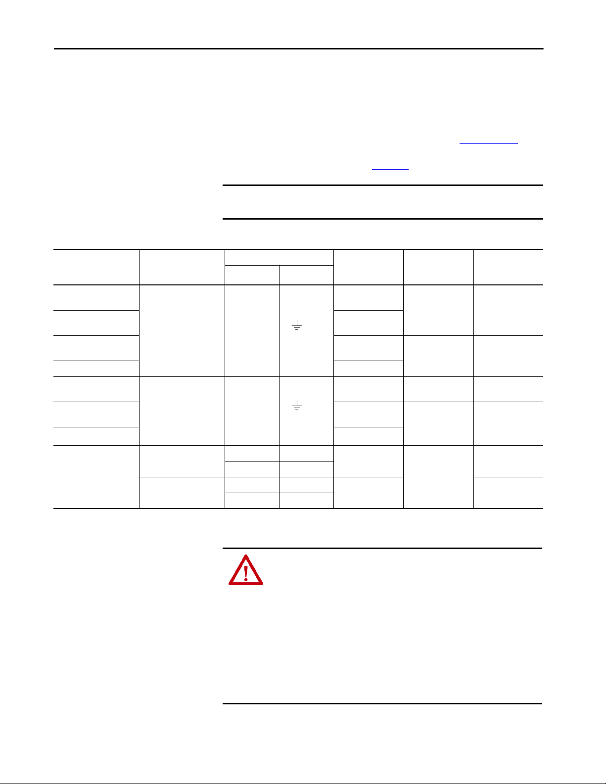
Connect the Kinetix 6000 Drive System Chapter 5
L3
L2
L1
DCDC+
L3
L2
L1
DCDC+
Power Wiring Requirements
Wire must be copper with 75 °C (167 °F) minimum rating. Phasing of main
AC power is arbitrary and earth ground connection is required for safe and
proper operation.
For IPIM module power wiring requirements, refer to the Kinetix 6000M
Integrated Drive-Motor System User Manual, publication 2094-UM003
Refer to Power Wiring Examples on page 189
IMPORTANT The National Electrical Code and local electrical codes take precedence
over the values and methods provided.
Table 60 - IAM Power Wiring Requirements
Kinetix 6000 Drive
Cat. No.
2094-AC05-Mxx-x
2094-AC09-M02-x
2094-AC16-M03-x
2094-AC32-M05-x 30 (3)
2094-BC01-Mxx-x
2094-BC02-M02-x
2094-BC04-M03-x
2094-BC07-M05-x 30 (3)
Description
(1)
DC bus
and
VAC input power
(1)
DC bus
and
VAC input power
Connects to Terminals Recommended Wire
Pin Signal
IPD-1
IPD-2
IPD-3
IPD-4
IPD-5
IPD-6
IPD-1
IPD-2
IPD-3
IPD-4
IPD-5
IPD-6
Size
mm
6…2.5
(10…14)
6…4
(10…12)
30…10
(3…8)
10…2.5
(8…14)
10…6
(8…10)
2
(AWG)
for interconnect diagrams.
Strip Length
mm (in.)
10
(0.38)
16
(0.63)
10
(0.38)
16
(0.63)
Tor que Val ue
N•m (lb•in)
0.5…0.6
(4.4…5.3)
2.4…3.0
(21.6…26.5)
1.2…1.5
(10.6…13.2)
2.4…3.0
(21.6…26.5)
.
Control input power
2094-xCxx-Mxx-x
Contactor Enable
(1) Keep DC common-bus connections (leader IAM to follower IAM module) as s hort as possible.
(2) The actual gauge of the contactor enable wiring depends on the system configuration. Consult your machine builder, the NEC, and applicable local codes.
CPD-1 CTRL 2
CPD-2 CTRL 1
CED-1 CONT EN-
CED-2 CONT EN+
4…2.5
(12…14)
4…2.5
(12…14)
10
(0.38)
(2)
ATT EN TI ON : To avoid personal injury and/or equipment damage, make sure
installation complies with specifications regarding wire types, conductor
sizes, branch circuit protection, and disconnect devices. The National
Electrical Code (NEC) and local codes outline provisions for safely installing
electrical equipment.
ATT EN TI ON : To avoid personal injury and/or equipment damage, make sure
motor power connectors are used for connection purposes only. Do not use
them to turn the unit on and off.
ATT EN TI ON : To avoid personal injury and/or equipment damage, make sure
shielded power cables are grounded to prevent potentially high voltages on
the shield.
Rockwell Automation Publication 2094-UM001J-EN-P - March 2017 97
0.5…0.6
(4.4…5.3)
0.5…0.6
(4.4…5.3)
Page 98

Chapter 5 Connect the Kinetix 6000 Drive System
W
V
U
Table 61 - IAM/AM Power Wiring Requirements
Kinetix 6000 Drive
Cat. No.
2094-AC05-Mxx-x,
2094-AC09-M02-x,
2094-BC01-Mxx-x,
2094-BC02-M02-x,
2094-AMP5-x, 2094-AM01-x,
2094-AM02-x, 2094-BMP5-x,
2094-BM01-x, 2094-BM02-x
2094-AC16-M03-x,
2094-AC32-M05-x,
2094-BC04-M03-x,
2094-AM03-x, 2094-AM05-x,
2094-BM03-x
2094-BC07-M05-x,
2094-BM05-x
IAM or AM
(230 or 460V)
2094-xCxx-Mxx-x and
2094-xMxx-x
IAM or AM
(230 or 460V)
209
4-x
Cxx-Mxx-S and
2094-xMxx-S
Description
Motor power
Brake power
Safe torque-off
Connects to Terminals Recommended
Pin Signal
MP-4
MP-3
MP-2
MP-1
BC-6
BC-5
BC-4
BC-3
BC-2
BC-1
STO-1
STO-2
STO-3
STO-4
STO-5
STO-6
STO-7
STO-8
STO-9
MBRKMBRK+
COM
PWR
DBRKDBRK+
FDBK2+
FDBK2FDBK1+
FDBK1SAFETY ENABLE2+
SAFETY ENABLESAFETY ENABLE1+
24V +
24V_COM
Wire Size
2
(AWG)
mm
Strip Length
mm (in.)
Motor power cable
depends on motor/
drive combination.
10 (0.38)
6…1.5
(10…16)
10…1.5
(8…16)
30…2.5
(3…14)
10 (0.38)
16 (0.63)
0.75 (18) 10 (0.38)
0.75 (18)
(stranded wire with
ferrule)
7.0 (0.275) 0.235 (2.0)
1.5 (16)
(solid wire)
Tor que V alue
N•m (lb•in)
0.5…0.6
(4.4…5.3)
1.2…1.5
(10.6…13.2)
2.4…3.0
(21.6…26.5)
0.22…0.25
(1.9…2.2)
Drive Module Cat. No. Description
1394-SRxxxx
2094-BSP2
External passive shunt module
Shunt module
(200/400V-class)
Thermal switch
(1) 105 °C (221 °F), 600V.
Table 62 - Shunt Module Power Wiring Requirements
Connects to Terminals Recommended Wire
Pin Signal
RC-1 DC+
RC-2 INT
RC-3 COL
TS-1 TS 1
TS-2 TS 2
Size
mm
10 (8)
0.75 (18)
2
(AWG)
(1)
Tor que V alue
N•m (lb•in)
1.2…1.5
(10.6…13.2)
0.22…0.25
(1.9…2.2)
98 Rockwell Automation Publication 2094-UM001J-EN-P - March 2017
Page 99

Connect the Kinetix 6000 Drive System Chapter 5
Power Wiring Guidelines
Use these guidelines as a reference when wiring the power connectors on your
IAM and AM drive modules.
For IPIM module power wiring guidelines, refer to the Kinetix 6000M
Integrated Drive-Motor System User Manual, publication 2094-UM003
IMPORTANT For connector locations of the Kinetix 6000 drive modules, refer to 2094
IAM/AM Module Connector Data on page 58
When tightening screws to secure the wires, refer to the tables beginning on
for torque values.
page 97
When removing insulation from wires, refer to the tables beginning on
for strip lengths.
page 97
IMPORTANT To improve system performance, run wires and cables in the wireways as
established in Establishing Noise Zones on page 37
Follow these steps when wiring the connectors on your IAM and AM drive
modules.
1. Prepare the wires for attachment to each connector plug by removing
insulation equal to the recommended strip length.
.
.
.
IMPORTANT Use caution not to nick, cut, or otherwise damage strands as you
remove the insulation.
2. Route the cable/wires to your IAM and AM drive modules.
3. Insert wires into connector plugs.
Refer to connector pinout tables in Chapter
diagrams in Appendix
4. Tighten the connector screws.
5. Gently pull on each wire to make sure it does not come out of its
terminal; reinsert and tighten any loose wires.
6. Insert the connector plug into the module connector.
A.
4 or the interconnect
Rockwell Automation Publication 2094-UM001J-EN-P - March 2017 99
Page 100

Chapter 5 Connect the Kinetix 6000 Drive System
CTRL 2
CTRL 1
1 2
Kinetix 6000
IAM Module, Top View
Wiring the IAM/AM Module
Connectors
This section provides examples and wiring tables to assist you in making
connections to the IAM and AM modules.
Wire the Control Power (CPD) Connector
This example applies to any IAM, leader IAM, or follower IAM module.
Figure 49 - IAM Module (CPD connector)
IMPORTANT The 2094-AL75S, 2094-BL75S, and 2094-XL75S-C2 LIM modules can supply
input power for up to eight axes. The 2094-XL75S-C1 LIM module can
supply up to sixteen axes.
The IPIM module control power load must be calculated for Kinetix 6000M
systems and the LIM module control power input must have a sufficient
current rating. If no LIM module can support the current requirement, then
discrete components must be used.
The National Electrical Code and local electrical codes take precedence over
the values and methods provided. Implementation of these codes is the
responsibility of the machine builder.
Refer to Control Power on page 77
(without LIM module) on page 192
Table 63 - Control Power (CPD) Connector
CPL Connector (LIM module) or Other Single-phase Input
2094-ALxxS, 2094-BLxxS, or
2094-XL75S-Cx LIM Module
CPL Pin Signal CPL Pin Signal CPD Pin Signal
1 CTRL 1 2 L1 1 CTRL 2
2 CTRL 2 1 L2/N 2 CTRL 1
2094-AL09 and 2094-BL02
LIM Module
CPD Connector
(IAM module)
for more information and IAM Module
for the interconnect drawing.
Recommended
Wire Size
2
(AWG)
mm
2.5 (14) 10 (0.38)
Strip Length
mm (in.)
Tor que V alue
N•m (lb•in)
0.5…0.6
(4.4…5.3)
100 Rockwell Automation Publication 2094-UM001J-EN-P - March 2017
 Loading...