

Page 1

User Manual
Micro800 Plug-in Modules
Catalog Numbers
IF4, 2080-OF2, 2080-TC2, 2080-RTD2, 2080-MEMBAK-RTC, 2080-TRIMPOT6, 2080-SERIALISOL, 2080-DNET20,
2080-MOT-HSC
2080-IQ4, 2080-IQ4OB4, 2080-IQ4OV4, 2080-OB4, 2080-OV4, 2080-OW4I, 2080-IF2, 2080-
Page 2
Important User Information
IMPORTANT
Solid-state equipment has operational characteristics differing from those of electromechanical equipment. Safety
Guidelines for the Application, Installation and Maintenance of Solid State Controls (publication SGI-1.1
your local Rockwell Automation sales office or online at http://www.rockwellautomation.com/literature/
important differences between solid-state equipment and hard-wired electromechanical devices. Because of this difference,
and also because of the wide variety of uses for solid-state equipment, all persons responsible for applying this equipment
must satisfy themselves that each intended application of this equipment is acceptable.
In no event will Rockwell Automation, Inc. be responsible or liable for indirect or consequential damages resulting from
the use or application of this equipment.
The examples and diagrams in this manual are included solely for illustrative purposes. Because of the many variables and
requirements associated with any particular installation, Rockwell Automation, Inc. cannot assume responsibility or
liability for actual use based on the examples and diagrams.
No patent liability is assumed by Rockwell Automation, Inc. with respect to use of information, circuits, equipment, or
software described in this manual.
Reproduction of the contents of this manual, in whole or in part, without written permission of Rockwell Automation,
Inc., is prohibited.
Throughout this manual, when necessary, we use notes to make you aware of safety considerations.
WARNING: Identifies information about practices or circumstances that can cause an explosion in a hazardous
environment, which may lead to personal injury or death, property damage, or economic loss.
available from
) describes some
ATTENTION: Identifies information about practices or circumstances that can lead to personal injury or death,
property damage, or economic loss. Attentions help you identify a hazard, avoid a hazard, and recognize the
consequence
SHOCK HAZARD: Labels may be on or inside the equipment, for example, a drive or motor, to alert people that
dangerous voltage may be present.
BURN HAZARD: Labels may be on or inside the equipment, for example, a drive or motor, to alert people that
surfaces may reach dangerous temperatures.
Identifies information that is critical for successful application and understanding of the product.
Allen-Bradley, Rockwell Software, Rockwell Automation, Micro800, Micro820, Micro830, Micro850, Kinetix, PowerFlex, CompactBlock, KwikLink, Connected Components Workbench, and TechConnect are trademarks
of Rockwell Automation, Inc.
Trademarks not belonging to Rockwell Automation are property of their respective companies.
Page 3

Preface
Read this preface to familiarize yourself with the rest of the manual. It provides
information concerning:
• who should use this manual
• the purpose of this manual
• related documentation
• supporting information for Micro800™ plug-in modules and accessories
Who Should Use this Manual
Use this manual if you are responsible for designing, installing, programming, or
troubleshooting control systems that use Micro800 controllers.
You should have a basic understanding of electrical circuitry and familiarity with
relay logic. If you do not, obtain the proper training before using this product.
Purpose of this Manual
This manual is a reference guide for Micro800 controllers, plug-in modules and
accessories. It describes the procedures you use to install, wire, and troubleshoot
your controller. This manual:
• explains how to install and wire your plug-ins
• gives you an overview of the Micro800 plug-in modules and accessories
Refer to the additional resources for more information on other element of the
Micro800 system.
Additional Resources
These documents contain additional information concerning related Rockwell
Automation products.
Resource Description
Micro800 Programmable Controller External AC Power Supply
Installation Instructions 2080-IN001
Micro830 Programmable Controllers Installation Instructions
2080-IN002
Micro830 Programmable Controllers Installation Instructions
2080-IN003
Micro830 Programmable Controllers Installation Instructions
2080-IN004
Micro830 Programmable Controllers Installation Instructions
2080-IN005
Micro850 Programmable Controllers Installation Instructions
2080-IN007
Micro850 Programmable Controllers Installation Instructions
2080-IN008
Micro820 Programmable Controllers Installation Instructions
2080-IN009
Micro800 Remote LCD Installation Instructions 2080-IN010
Information on mounting and wiring the Micro800 Remote LCD module.
Information on mounting and wiring the optional external power supply.
Information on mounting and wiring the Micro830 10-point controllers.
Information on mounting and wiring the Micro830 16-point controllers.
Information on mounting and wiring the Micro830 24-point controllers.
Information on mounting and wiring the Micro830 48-point controllers.
Information on mounting and wiring the Micro850 24-point controllers.
Information on mounting and wiring the Micro850 48-point controllers.
Information on mounting and wiring the Micro820 20-point controllers.
Rockwell Automation Publication 2080-UM004C-EN-E - March 2015 iii
Page 4

Preface
Resource Description
Micro800 RS232/485 Isolated Serial Port Plug-in Module Wiring
Diagrams 2080-WD002
Micro800 Non-isolated Unipolar Analog Input Plug-in Module Wiring
Diagrams 2080-WD003
Micro800 Non-isolated Unipolar Analog Output Plug-in Module Wiring
Diagrams 2080-WD004
Micro800 Non-isolated RTD Plug-in Module Wiring Diagrams
2080-WD005
Micro800 Non-isolated Thermocouple Plug-in Module Wiring Diagrams
2080-WD006
Micro800 Memory Backup and High Accuracy RTC Plug-In Module
Wiring Diagrams 2080-WD007
Micro800 6-Channel Trimpot Analog Input Plug-In Module Wiring
Diagrams 2080-WD008
Micro800 Digital Relay Output Plug-in Module Wiring Diagrams
2080-WD010
Micro800 Digital Input, Output, and Combination Plug-in Modules
Wiring Diagrams 2080-WD011
Micro800 High-speed Counter Plug-in Module 2080-WD012
Micro800 DeviceNet Plug-in Module 2080-WD013 Specifications and information on wiring the Micro800 DeviceNet plug-in
Micro820 Programmable Controller User Manual,
publication 2080-UM005
Micro830 and Micro850 Programmable Controller User Manual,
publication 2080-UM002
Industrial Automation Wiring and Grounding Guidelines, publication
1770-4.1
Product Certifications website, http://www.rockwellautomation.com/
products/certification/
Application Considerations for Solid-State Controls SGI-1.1
National Electrical Code - Published by the National Fire Protection
Association of Boston, MA.
Allen-Bradley Industrial Automation Glossary AG-7.1 A glossary of industrial automation terms and abbreviations.
Specifications and information on wiring the Micro800 high-speed counter
A description of important differences between solid-state programmable
Information on mounting and wiring the Micro800 RS232/485 isolated serial
port plug-in module.
Information on mounting and wiring the Micro800 non-isolated unipolar analog
input plug-in module.
Information on mounting and wiring the Micro800 non-isolated unipolar analog
output plug-in module.
Information on mounting and wiring the Micro800 non-isolated RTD plug-in
module.
Information on mounting and wiring the Micro800 non-isolated thermocouple
plug-in module.
Information on mounting and wiring the Micro800 memory backup and high
accuracy RTC plug-in module.
Information on mounting and wiring the Micro800 6-channel trimpot analog
input plug-in module.
Information on mounting and wiring the Micro800 digital relay output plug-in
module.
Information on mounting and wiring the Micro800 digital input, output, and
combination plug-in module.
plug-in module.
module.
Information on features, installation, wiring and usage of the Micro820
controllers.
Information on features, installation, wiring and usage of the Micro830 and
Micro850 controllers.
Provides general guidelines for installing a Rockwell Automation industrial
system.
Provides declarations of conformity, certificates, and other certification details.
controller products and hard-wired electromechanical devices.
An article on wire sizes and types for grounding electrical equipment.
You can view or download publications at http://www.rockwellautomation.com/
literature/. To order paper copies of technical documentation, contact your local
Rockwell Automation distributor or sales representative.
You can download the latest version of Connected Components Workbench for
your Micro800 at the URL below.
http://ab.rockwellautomation.com/Programmable-Controllers/ConnectedComponents-Workbench-Software.
iv Rockwell Automation Publication 2080-UM004C-EN-E - March 2015
Page 5

Table of Contents
Preface
Micro800 Plug-in Modules
Who Should Use this Manual . . . . . . . . . . . . . . . . . . . . . . . . . . . . . . . . . . . . . . iii
Purpose of this Manual . . . . . . . . . . . . . . . . . . . . . . . . . . . . . . . . . . . . . . . . . . . . iii
Additional Resources . . . . . . . . . . . . . . . . . . . . . . . . . . . . . . . . . . . . . . . . . . . . . . iii
Chapter 1
Digital Plug-ins . . . . . . . . . . . . . . . . . . . . . . . . . . . . . . . . . . . . . . . . . . . . . . . . . . . . 2
12/24V Digital Plug-ins — 2080-IQ4, 2080-IQ4OB4, 2080-
IQ4OV4, 2080-OB4, 2080-OV4 . . . . . . . . . . . . . . . . . . . . . . . . . . . . . . . . 2
AC/DC Relay Output Module — 2080-OW4I. . . . . . . . . . . . . . . . . . . 3
Analog Plug-ins . . . . . . . . . . . . . . . . . . . . . . . . . . . . . . . . . . . . . . . . . . . . . . . . . . . . 3
Non-isolated Unipolar Analog Input and Output — 2080-IF2,
2080-IF4, 2080-OF2 . . . . . . . . . . . . . . . . . . . . . . . . . . . . . . . . . . . . . . . . . . . 3
Specialty Plug-ins . . . . . . . . . . . . . . . . . . . . . . . . . . . . . . . . . . . . . . . . . . . . . . . . . . 3
Non-isolated Thermocouple and RTD — 2080-TC2 and 2080-
RTD2 . . . . . . . . . . . . . . . . . . . . . . . . . . . . . . . . . . . . . . . . . . . . . . . . . . . . . . . . . 3
Memory Backup and High Accuracy RTC — 2080-MEMBAK-RTC
3
Six-channel Trimpot — 2080-TRIMPOT6 . . . . . . . . . . . . . . . . . . . . . . 4
High Speed Counter — 2080-MOT-HSC . . . . . . . . . . . . . . . . . . . . . . . 4
Communication Plug-ins . . . . . . . . . . . . . . . . . . . . . . . . . . . . . . . . . . . . . . . . . . . 4
RS232/RS485 Isolated Serial Port — 2080-SERIALISOL . . . . . . . . . 4
DeviceNet Scanner — 2080-DNET20 . . . . . . . . . . . . . . . . . . . . . . . . . . . 5
Install and Wire Your Module
Non-isolated Thermocouple
and RTD
Plug-in Modules – 2080-TC2 and
2080-RTD2
Chapter 2
Hardware Features . . . . . . . . . . . . . . . . . . . . . . . . . . . . . . . . . . . . . . . . . . . . . . . . . 7
Insert Module into Controller. . . . . . . . . . . . . . . . . . . . . . . . . . . . . . . . . . . . . . . 7
Wiring . . . . . . . . . . . . . . . . . . . . . . . . . . . . . . . . . . . . . . . . . . . . . . . . . . . . . . . . . . . . 8
Wiring Considerations and Applications for 2080-TC2 . . . . . . . . . . . . . 12
Type of CJC Sensor . . . . . . . . . . . . . . . . . . . . . . . . . . . . . . . . . . . . . . . . . . 12
Wire the CJC Thermistor on the 2080-TC2 Module. . . . . . . . . . . . 12
Wiring Considerations and Applications for 2080-RTD2 . . . . . . . . . . . 13
Two-wire and Three-Wire Wiring . . . . . . . . . . . . . . . . . . . . . . . . . . . . 13
Wire the RTD Sensors. . . . . . . . . . . . . . . . . . . . . . . . . . . . . . . . . . . . . . . . 13
Wire the RTD Module and RTD Sensor in the Field . . . . . . . . . . . . 14
Wiring Applications for 2080-MOT-HSC . . . . . . . . . . . . . . . . . . . . . . . . . 16
Chapter 3
Thermocouple Module . . . . . . . . . . . . . . . . . . . . . . . . . . . . . . . . . . . . . . . . . . . 19
Thermocouple Sensor Types and Ranges . . . . . . . . . . . . . . . . . . . . . . . 19
RTD Module . . . . . . . . . . . . . . . . . . . . . . . . . . . . . . . . . . . . . . . . . . . . . . . . . . . . 20
RTD Sensor Types and Ranges . . . . . . . . . . . . . . . . . . . . . . . . . . . . . . . . 20
Connected Components Workbench Global Variables
Data Maps. . . . . . . . . . . . . . . . . . . . . . . . . . . . . . . . . . . . . . . . . . . . . . . . . . . . . . . 22
Temperature Conversion – Data to Degree Celsius (°C) . . . . . . . . . 23
Rockwell Automation Publication 2080-UM004C-EN-E - March 2015 v
Page 6

Table of Contents
Chapter 4
High Speed Counter – 2080MOT-HSC
DeviceNet Plug-in – 2080DNET20
Overview . . . . . . . . . . . . . . . . . . . . . . . . . . . . . . . . . . . . . . . . . . . . . . . . . . . . . . . . 25
Counter Specifications. . . . . . . . . . . . . . . . . . . . . . . . . . . . . . . . . . . . . . . . . . . . 25
Number of Counters: 1 to 2 . . . . . . . . . . . . . . . . . . . . . . . . . . . . . . . . . . . 26
Up Counter . . . . . . . . . . . . . . . . . . . . . . . . . . . . . . . . . . . . . . . . . . . . . . . . . . 27
Counter with External Direction. . . . . . . . . . . . . . . . . . . . . . . . . . . . . . . 28
Understanding Rates. . . . . . . . . . . . . . . . . . . . . . . . . . . . . . . . . . . . . . . . . . 33
User Defined Function Blocks. . . . . . . . . . . . . . . . . . . . . . . . . . . . . . . . . . . . . 35
RA_HSCPlugIn. . . . . . . . . . . . . . . . . . . . . . . . . . . . . . . . . . . . . . . . . . . . . . 35
Use the 2080-MOT-HSC Module . . . . . . . . . . . . . . . . . . . . . . . . . . . . . 38
Chapter 5
Overview . . . . . . . . . . . . . . . . . . . . . . . . . . . . . . . . . . . . . . . . . . . . . . . . . . . . . . . . 39
Status Indicators . . . . . . . . . . . . . . . . . . . . . . . . . . . . . . . . . . . . . . . . . . . . . . . . . 39
Network Configuration. . . . . . . . . . . . . . . . . . . . . . . . . . . . . . . . . . . . . . . . . . . 40
Network Wiring. . . . . . . . . . . . . . . . . . . . . . . . . . . . . . . . . . . . . . . . . . . . . . 40
DeviceNet Switches. . . . . . . . . . . . . . . . . . . . . . . . . . . . . . . . . . . . . . . . . . . 41
Power Supply. . . . . . . . . . . . . . . . . . . . . . . . . . . . . . . . . . . . . . . . . . . . . . . . . 42
User Defined Function Blocks. . . . . . . . . . . . . . . . . . . . . . . . . . . . . . . . . . . . . 45
RA_DNET_MASTER . . . . . . . . . . . . . . . . . . . . . . . . . . . . . . . . . . . . . . . 45
RA_DNET_NODE_STATUS. . . . . . . . . . . . . . . . . . . . . . . . . . . . . . . . 46
RA_DNET_LDX_DISCRETE . . . . . . . . . . . . . . . . . . . . . . . . . . . . . . . 47
RA_DNET_LDX_ANALOG . . . . . . . . . . . . . . . . . . . . . . . . . . . . . . . . 48
RA_DNET_LDX_TC_RTD . . . . . . . . . . . . . . . . . . . . . . . . . . . . . . . . . 49
RA_PF_DNET_STANDARD. . . . . . . . . . . . . . . . . . . . . . . . . . . . . . . . 50
RA_PF_DNET_MULTIDRIVE . . . . . . . . . . . . . . . . . . . . . . . . . . . . . . 51
RA_DNET_OVERLOAD. . . . . . . . . . . . . . . . . . . . . . . . . . . . . . . . . . . . 53
RA_DNET_GENERIC . . . . . . . . . . . . . . . . . . . . . . . . . . . . . . . . . . . . . . 53
Send Explicit Messages to 2080-DNET20 Plug-in Using Micro800 Pass
Through. . . . . . . . . . . . . . . . . . . . . . . . . . . . . . . . . . . . . . . . . . . . . . . . . . . . . . . . . 56
Error Codes. . . . . . . . . . . . . . . . . . . . . . . . . . . . . . . . . . . . . . . . . . . . . . . . . . . . . . 57
Use the 2080-DNET20 Plug-in. . . . . . . . . . . . . . . . . . . . . . . . . . . . . . . . 58
Appendix A
Specifications
Digital Plug-in Modules. . . . . . . . . . . . . . . . . . . . . . . . . . . . . . . . . . . . . . . . . . . 59
Analog Plug-in Modules . . . . . . . . . . . . . . . . . . . . . . . . . . . . . . . . . . . . . . . . . . 64
Specialty Plug-in Modules . . . . . . . . . . . . . . . . . . . . . . . . . . . . . . . . . . . . . . . . . 66
Communication Plug-in Modules . . . . . . . . . . . . . . . . . . . . . . . . . . . . . . . . . 73
Appendix B
Quickstart
vi Rockwell Automation Publication 2080-UM004C-EN-E - March 2015
Add and Configure Plug-ins in Connected Components Workbench. 79
Browse Your 2080-DNET20 Plug-in Using RSLinx. . . . . . . . . . . . . . . . . 81
Browse Using the DeviceNet Network . . . . . . . . . . . . . . . . . . . . . . . . . 82
Browse Using the Micro800 Pass Through . . . . . . . . . . . . . . . . . . . . . 83
Page 7

Chapter 1
Flash Upgrade Your
2080-DNET20 Plug-in Firmware . . . . . . . . . . . . . . . . . . . . . . . . . . . . . . . . . 84
Quickstart Project for
2080-DNET20 Plug-in . . . . . . . . . . . . . . . . . . . . . . . . . . . . . . . . . . . . . . . . . . . 88
Setup and Wiring. . . . . . . . . . . . . . . . . . . . . . . . . . . . . . . . . . . . . . . . . . . . . 89
Configuration. . . . . . . . . . . . . . . . . . . . . . . . . . . . . . . . . . . . . . . . . . . . . . . . 90
Build and Download. . . . . . . . . . . . . . . . . . . . . . . . . . . . . . . . . . . . . . . . . . 92
Execute Program . . . . . . . . . . . . . . . . . . . . . . . . . . . . . . . . . . . . . . . . . . . . . 93
Quickstart Projects for
2080-MOT-HSC Plug-in. . . . . . . . . . . . . . . . . . . . . . . . . . . . . . . . . . . . . . . . . 93
Setup and Wiring. . . . . . . . . . . . . . . . . . . . . . . . . . . . . . . . . . . . . . . . . . . . . 94
Configuration for UDFB 1: RA_HSCPlugIn . . . . . . . . . . . . . . . . . . 95
Build and Download. . . . . . . . . . . . . . . . . . . . . . . . . . . . . . . . . . . . . . . . . . 96
Execute the Function Block . . . . . . . . . . . . . . . . . . . . . . . . . . . . . . . . . . . 96
Configuration for UDFB 2: RA_EncoderFDBK . . . . . . . . . . . . . . . 97
Build and Download. . . . . . . . . . . . . . . . . . . . . . . . . . . . . . . . . . . . . . . . . . 98
Execute the Function Block . . . . . . . . . . . . . . . . . . . . . . . . . . . . . . . . . . . 99
Configuration for HSC UDFB 3: RA_ServoFDBK . . . . . . . . . . . . 100
Build and Download. . . . . . . . . . . . . . . . . . . . . . . . . . . . . . . . . . . . . . . . . 101
Execute the Function Block . . . . . . . . . . . . . . . . . . . . . . . . . . . . . . . . . . 102
Error Codes
Index
Appendix C
Troubleshooting . . . . . . . . . . . . . . . . . . . . . . . . . . . . . . . . . . . . . . . . . . . . . . . . 105
Error Codes for Micro800 Plug-ins . . . . . . . . . . . . . . . . . . . . . . . . . . . . . . . 105
Calling Rockwell Automation for Assistance . . . . . . . . . . . . . . . . . . . . . . 106
Rockwell Automation Publication 2080-UM004C-EN-E - March 2015 vii
Page 8

Table of Contents
Notes:
viii Rockwell Automation Publication 2080-UM004C-EN-E - March 2015
Page 9
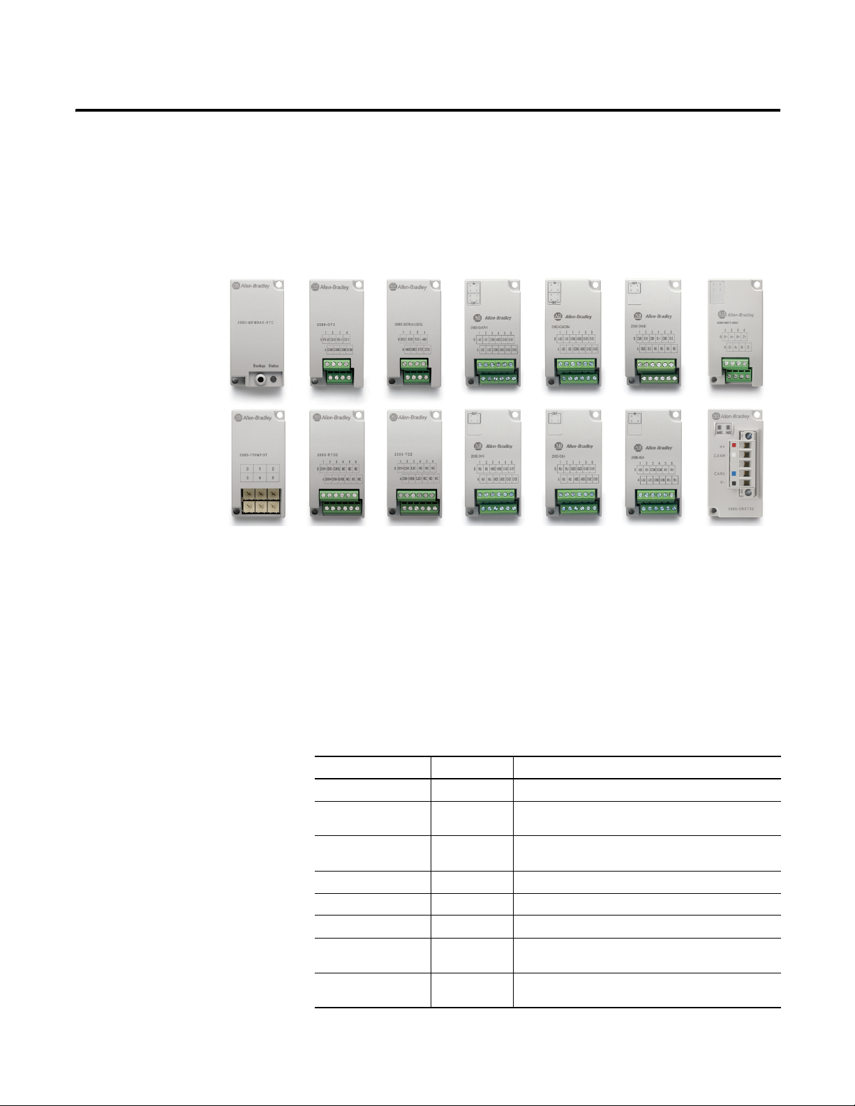
Micro800 Plug-in Modules
Chapter
1
Plug-in modules enhance the functionality of a base unit controller. With these
modules, you can:
• Extend the functionality of embedded I/O without increasing the
footprint of your controller.
• Improve performance by adding additional processing power or
capabilities.
• Add additional communication functionality.
Micro820, Micro830, and Micro850 support the following plug-in modules:
Micro800 Plug-in Modules
Module Type Description
2080-IQ4 Digital 4-point, 12/24V DC Sink/Source input
2080-IQ4OB4 Digital 8-point, Combo, 12/24V DC Sink/Source input
2080-IQ4OV4 Digital 8-point, Combo, 12/24V DC Sink/Source input
2080-OB4 Digital 4-point, 12/24V DC Source output
2080-OV4 Digital 4-point, 12/24V DC Sink output
2080-OW4I Digital 4-point, AC/DC Relay output
2080-IF2 Analog 2-channel, Non-isolated unipolar voltage/current
2080-IF4 Analog 4-channel, Non-isolated unipolar voltage/current
12/24V DC Source output
12/24V DC Sink output
analog input
analog input
Rockwell Automation Publication 2080-UM004C-EN-E - March 2015 1
Page 10
Chapter 1 Micro800 Plug-in Modules
Micro800 Plug-in Modules
Module Type Description
2080-OF2 Analog 2-channel, Non-isolated unipolar voltage/current
2080-TC2 Specialty 2-channel, non-isolated thermocouple module
2080-RTD2 Specialty 2-channel, non-isolated RTD module
2080-MEMBAK-RTC
2080-TRIMPOT6 Specialty 6-channel trimpot analog input
2080-MOT-HSC Specialty High speed counter
2080-DNET20 Communication 20-node DeviceNet scanner
2080-SERIALISOL Communication RS232/485 isolated serial port
(1) 2080-MEMBAK-RTC is not supported on Micro820 controllers.
(1)
Specialty Memory backup and high accuracy RTC
analog output
Number of support for Micro800 plug-ins on the controllers are summarized in
the following table.
Plug-in Slots on Micro800 Controllers
Digital Plug-ins
Controller Number of Plug-in Slots
Micro810 0
Micro820 2
Micro830 2 (10/16 points)
3 (24 points)
5 (48 points)
Micro850 3 (24 points)
5 (48 points)
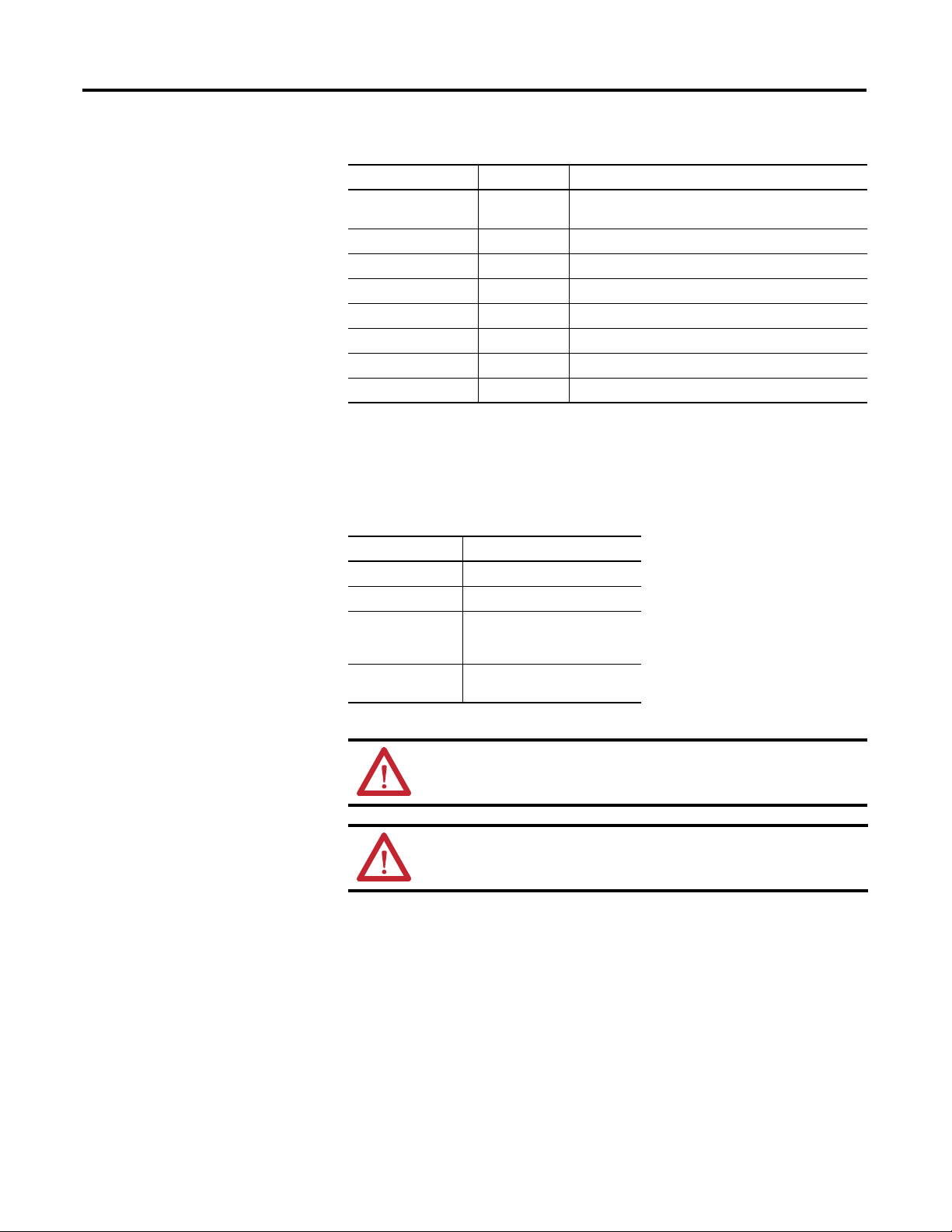
ATTENTION: Removal and Insertion Under Power (RIUP) is not supported
on all Micro800 plug-in modules, except on the 2080-MEMBAK-RTC
module.
ATTENTION: Micro800 plug-in modules can be installed on any plug-in
slot on the controller, except for the 2080-MEMBAK-RTC module which
can only be installed on the leftmost plug-in slot.
12/24V Digital Plug-ins — 2080-IQ4, 2080-IQ4OB4, 2080-IQ4OV4, 2080-OB4, 2080-OV4
These digital plug-in modules provide transistor outputs for switching a variety
of 12/24V DC voltages to field loads and for detecting 12/24V signals from field
devices.
2 Rockwell Automation Publication 2080-UM004C-EN-E - March 2015
Page 11

Micro800 Plug-in Modules Chapter 1
AC/DC Relay Output Module — 2080-OW4I
The 2080-OW4I is a 4-channel relay output and provides dry contact relay
closure outputs for switching a variety of AC and DC voltages to field loads.
Analog Plug-ins
Specialty Plug-ins
The following analog plug-ins are supported by most Micro800 controllers.
Non-isolated Unipolar Analog Input and Output — 2080-IF2, 2080-IF4, 2080-OF2
These plug-in modules add extra embedded non-isolated unipolar (0...10V,
0...20 mA) analog I/O and offer 12-bit resolution.
Non-isolated Thermocouple and RTD — 2080-TC2 and 2080-RTD2
These non-isolated plug-in modules help to make temperature control possible
when used with PID (Proportional Integral Derivative).
See Non-isolated Thermocouple and RTD Plug-in Modules – 2080-TC2 and
2080-RTD2 on page 19 for more information.
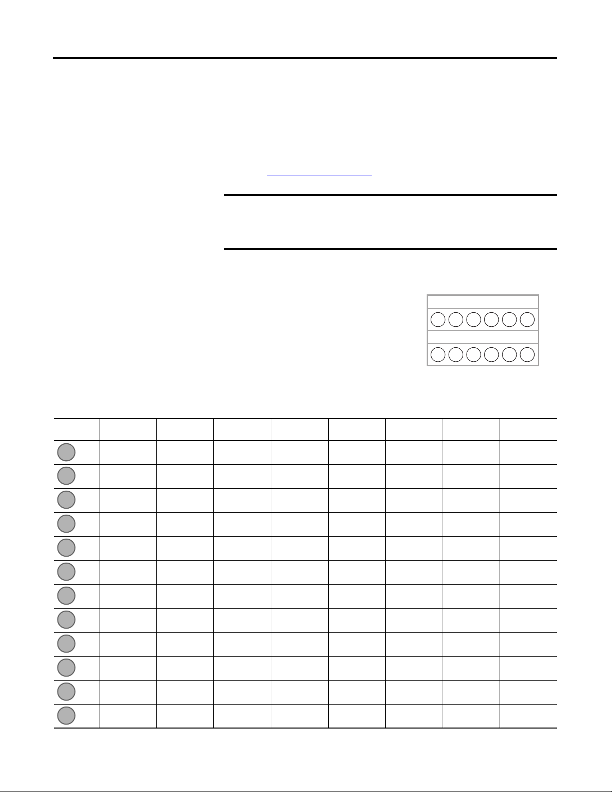
Memory Backup and High Accuracy RTC — 2080-MEMBAK-RTC
This plug-in allows you to make a backup copy of the project in your controller,
and adds precision real-time clock function without needing to calibrate or
update periodically.
It can also be used to clone/update Micro830 and Micro850 application code.
However, it cannot be used as additional Run-Time Program or Data Storage for
recipe and datalog.
Rockwell Automation Publication 2080-UM004C-EN-E - March 2015 3
Page 12

Chapter 1 Micro800 Plug-in Modules
45068
Channels
012
345
Status Indicators
State Description
Solid red (2 s) Startup cycle test in progress.
Flashing red Back up in progress.
Solid red (continuous) Battery low.
Project Backup and Restore
The project can be backed up and restored using Connected Components
Workbench software.
Six-channel Trimpot — 2080-TRIMPOT6
This trimpot plug-in offers an affordable method of adding six analog presets for
speed, position and temperature control.
High Speed Counter — 2080-MOT-HSC
This plug-in module provides enhanced high speed counter capabilities to the
Micro800 controller. It supports the same functionalities of an embedded HSC
on the Micro800 controllers but is enhanced to support up to 250 KHz 5V
differential line driver for improved noise immunity and provides additional
dedicated I/O.
For more information, see High Speed Counter – 2080-MOT-HSC
Communication Plug-ins
RS232/RS485 Isolated Serial Port — 2080-SERIALISOL
The 2080-SERIALISOL plug-in supports CIP Serial (RS-232 only), Modbus
RTU (RS232 and RS485), and ASCII (RS232 and RS485
(1)
the embedded Micro800 serial port, this port is electrically isolated, making it
ideal for connecting to noisy devices, such as variable frequency and servo drives,
(1) RS-485 support is only available from Connected Components Workbench revision 6.
4 Rockwell Automation Publication 2080-UM004C-EN-E - March 2015
on page 25.
) protocols. Unlike
Page 13

Micro800 Plug-in Modules Chapter 1
IMPORTANT
as well as for communications over long cable lengths. Depending on the
application and baud rate setting, you can extend this length.
2080-SERIALISOL is suitable for communication over longer cable length
of up to 1000 m using RS485, with up to 19200 bps baud rate.
The electrical characteristics of cable used and good wiring practices are
very critical in achieving reliable communication performance over longer
cable length. A shielded twisted pair RS485 22AWG cable (example:
3106A from Belden) is recommended. Terminate both ends of the cable
with 120 ohm resistance.
DeviceNet Scanner — 2080-DNET20
The Micro800 DeviceNet plug-in module serves as a scanner and client for
explicit messaging to remote devices including I/O and drives, using a proven and
well-accepted fieldbus/network. It also provides better performance than using
serial and Ethernet (EtherNet/IP Class 3) communications.
For more information, see the DeviceNet Plug-in – 2080-DNET20
on page 39.
Rockwell Automation Publication 2080-UM004C-EN-E - March 2015 5
Page 14

Chapter 1 Micro800 Plug-in Modules
Notes:
6 Rockwell Automation Publication 2080-UM004C-EN-E - March 2015
Page 15
Chapter
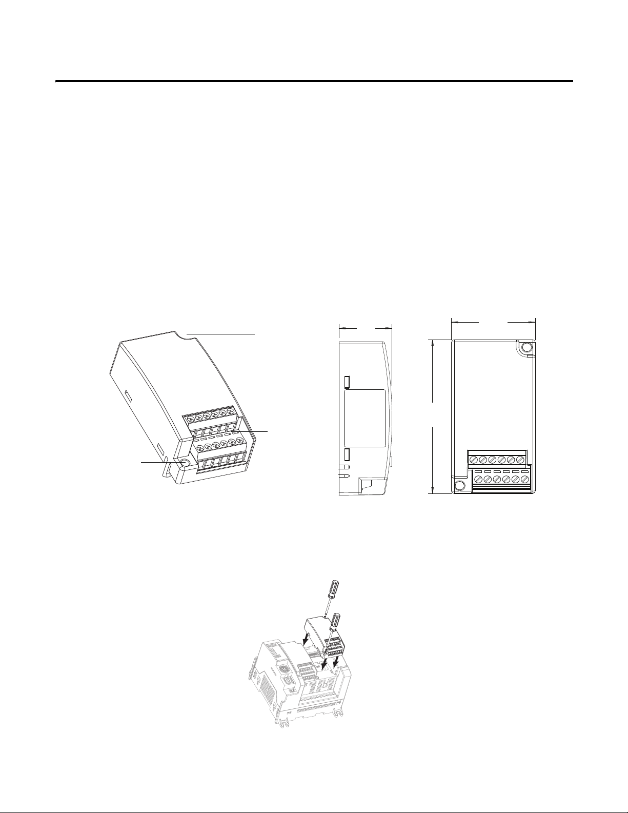
45010
terminal
block
mounting screw
hole
mounting
screw hole
20
(0.79)
31.5
(1.24)
62
(2.44)
Measurements in millimeters (inches)
45811
Side view Front view
2080-RTD2 shown
45012
Install and Wire Your Module
This chapter provides hardware features, installation, and wiring connection
diagrams for all the Micro800 plug-in modules.
2
Hardware Features
The plug-in modules, except for the 2080-MEMBAK-RTC, can be plugged into
any plug-in slots on the Micro800 controllers.
Insert Module into
Follow the instructions to insert and secure the plug-in module to the controller.
Controller
Rockwell Automation Publication 2080-UM004C-EN-E - March 2015 7
Page 16
Chapter 2 Install and Wire Your Module
IMPORTANT
Back
A
B
Front
Twelve-pin Female Terminal Block
A1
A2
A3
A4
A5A6B1B2B3B4B5
B6
1. Position the plug-in module with the terminal block facing the front of the controller as shown.
2. Snap the module into the module bay.
3. Using a screwdriver, tighten the 10…12 mm (0.39…0.47 in.) M3 self
tapping screw to torque specifications.
See Specifications
Analog I/O performance depends on the application. For better noise
immunity, cable length should ideally be less than 10 m because the
plug-ins are non-isolated. For longer cable length requirements, use the
2085 expansion I/O modules instead.
on page 59 for torque specifications.
Wiring
The following plug-in modules have 12-pin
female terminal blocks:
• 2080-IQ4,
• 2080-IQ4OB4, 2080-IQ4OV4
• 2080-OB4, 2080-OV4, 2080-OW4I
• 2080-IF2, 2080-IF4
• 2080-TC2, 2080-RTD2
Pin Designations for 12-Pin Female Terminal Block Modules
Pin 2080-IQ4 2080-IQ4OB4,
2080-IQ4OV4
I-02 I-02 Not used COM3 COM COM CH0+ CH0+
I-03 I-03 Not used O-3 Not used VI-2 CH0- CH0-
COM COM -24V DC Not used Not used CI-2 CJC+ CH0L (Sense)
COM -24V DC -24V DC Not used COM COM Not used Not used
Not used O-02 O-02 Not used Not used VI-3 Not used Not used
Not used O-03 O-03 Not used Not used CI-3 Not used Not used
2080-OB4,
2080-OV4
2080-OW4I 2080-IF2 2080-IF4 2080-TC2 2080-RTD2
1 2 3 4
1 2 3 4
5 6
5 6
8 Rockwell Automation Publication 2080-UM004C-EN-E - March 2015
I-00 I-00 Not used COM0 VI-0 VI-0 CH1+ CH1+
I-01 I-01 Not used O-0 CI-0 CI-0 CH1- CH1-
COM COM +24V DC COM1 COM COM CJC- CH1L (Sense)
COM +24V DC +24V DC O-1 VI-1 VI-1 Not used Not used
Not used O-00 O-00 COM2 CI-1 CI-1 Not used Not used
Not used O-01 O-01 O-2 COM COM Not used Not used
Page 17
1 2 3 4
Back
Front
B
A
Eight-pin female terminal block
0-
A-
B-
Z-
A+
B+
Z+
0+
DC(+)
DC(-)
CR
CR
0-
A-
B-
Z-
A+
B+
Z+
0+
DC(+)
DC(-)
Sinking Output Wiring
Sourcing Output Wiring
A1A2A3A4B1B2B3
B4
1 2 3 4
Install and Wire Your Module Chapter 2
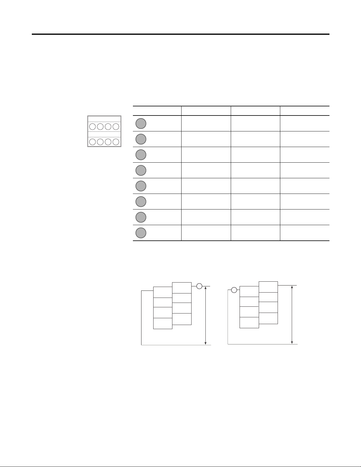
The following plug-in modules have eight-pin female terminal blocks:
• 2080-OF2
• 2080-SERIALISOL
• 2080-MOT-HSC
Pin Designations for 8-Pin Female Terminal Block Modules
Pin 2080-OF2 2080-SERIALISOL 2080-MOT-HSC
COM RS485 B+ O-
COM GND A-
COM RS232 RTS B-
COM RS232 CTS Z-
VO-0 RS232 DCD O+
CO-0 RS232 RXD A+
(1) (2)
VO-1 RS232 TXD B+
CO-1 RS485 A- Z+
(1) IMPORTANT: Individually shielded, twisted-pair cable (or the type recommended by the encoder or sensor
manufacturer) should be used for the 2080-MOT-HSC plug-in.
(2) Sinking Output/Sourcing Output wiring for the 2080-MOT-HSC plug-in is shown below.
Rockwell Automation Publication 2080-UM004C-EN-E - March 2015 9
Page 18
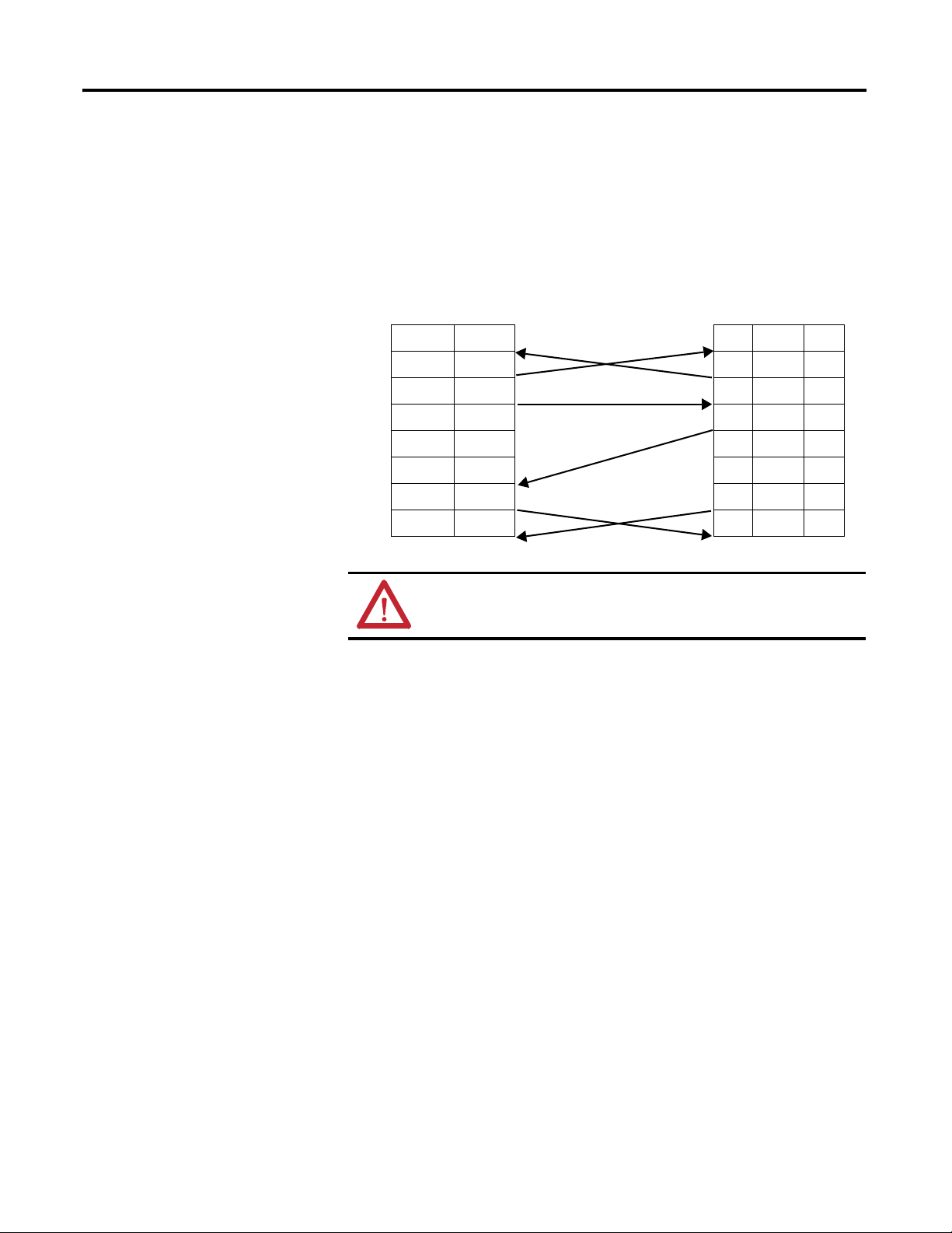
Chapter 2 Install and Wire Your Module
DTE Device
(Micro800 RS232
Isolated Serial Port
Plug-in Module)
DCE Device
(Modem, and
so on)
8-Pin 25-Pin 9-Pin
B3 TXD TXD 2 3
B2 RXD RXD 3 2
A2 GND GND 7 5
A1 B(+) DCD 8 1
B4 A(-) DTR 20 4
B1 DCD DSR 6 6
A4 CTS CTS 5 8
A3 RTS RTS 4 7
Serial Port to Modem Cable Pinout
When connecting Micro800 to a modem using an RS-232 cable, the maximum
that the cable length may be extended is 15.24 m (50 ft).
ATTENTION: Do not connect to pins A1 and B4 for RS-232
connections. This connection will cause damage to the RS-232/485
communication port.
10 Rockwell Automation Publication 2080-UM004C-EN-E - March 2015
Page 19
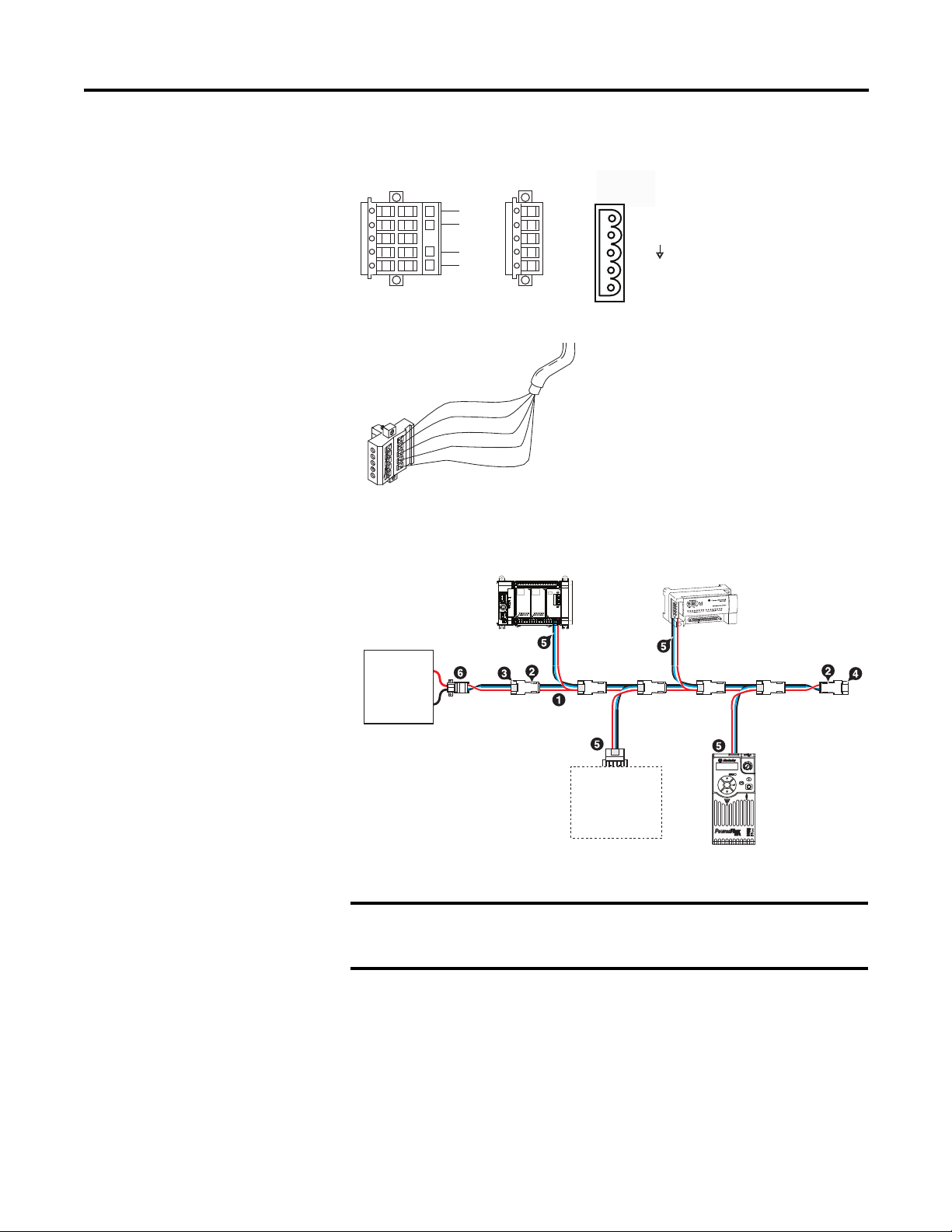
2080-DNET20 – 6-pin Female Terminal Block
IMPORTANT
Color Chips (dots)
Red Dot
Black Dot
Blue Dot
White Dot
10-position Plug
5-position Plug
D
D
D
D
D
Linear Plug
10-position
Drop Line or
DeviceNet
Trunk Cable
Red
White
Bare
Blue
Black
DeviceNet
Port Pinout
V+ (RED)
CANH (WHITE)
SHIELD
CANL (BLUE)
V- (BLACK)
20474
Esc
Sel
Micro800 controller
CompactBlock LDX
COMM
power
supply
Component on
DeviceNet
network
PowerFlex
Drive 523 via
25-COMM-D
COMM
power
supply
1 KwikLink Lite IP20 flat media
2 Trunk line connector
3 Drop line connector
4 Terminating resistor
5 5-pin open style connector
6 Power tap with terminating resistor
46220
Install and Wire Your Module Chapter 2
2080-DNET20: Sample network wiring using KwikLink™ Lite Flat media
Individually shielded, twisted-pair cable (or the type recommended by the
encoder or sensor manufacturer) should be used for the
2080-MOT-HSC plug-in.
Rockwell Automation Publication 2080-UM004C-EN-E - March 2015 11
Page 20
Chapter 2 Install and Wire Your Module
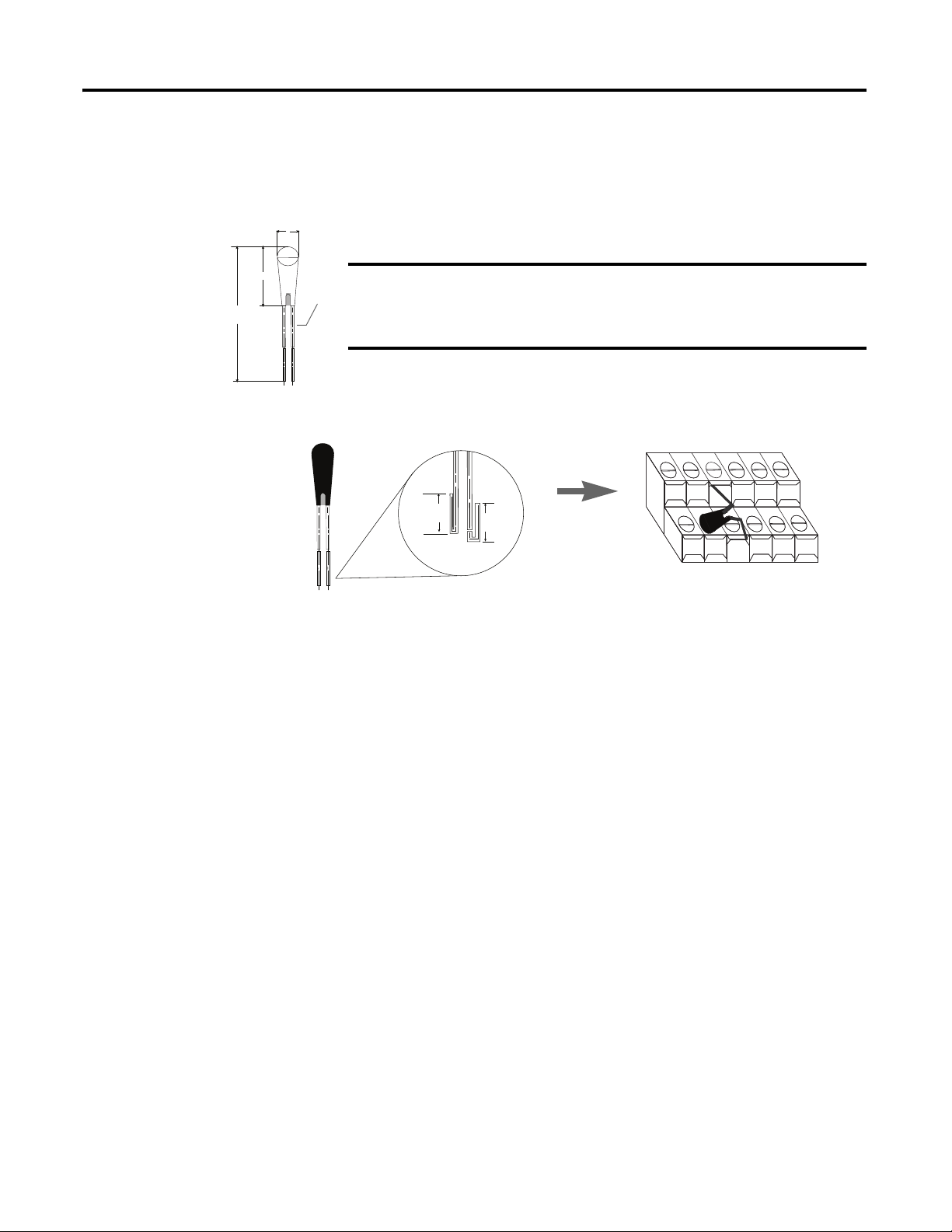
IMPORTANT
6.5 max
50 ± 2
0.25
2.41 max
1. Connect the thermocouples to
channel 0 and 1, respectively.
Then, connect and screw the
thermistor to terminals A3 and B3.
2. Once fitted, bend the black bead
of the thermistor such that it
makes contact with the A2 screw
securely.
A1 A2 A3 A4 A5 A6
B1 B2 B3 B4 B5 B6
Wiring Considerations and Applications for 2080-TC2
Type of CJC Sensor
The CJC sensor is a non-polarized, passive negative temperature co-efficient
thermistor (EPCOS B57869S0502F140). It is readily available in the market
with most third party suppliers/vendors.
CJC Channel Error
The CJC channel on 2080-TC2 has a worst-case error of ±1.2 °C @ 25 °C.
This error does not include the manufacturer-specified sensor error
±0.2 °C @ 25 °C.
Wire the CJC Thermistor on the 2080-TC2 Module
5m
B3
5m
A3
The position for the thermistor, as illustrated, helps to compensate for
thermoelectric voltages developed at screw junction equally for thermocouples
connected to channels 0 and 1. If the bead is not in proper contact with the screw,
there will be deviation in readings due to inadequate isothermal compensation.
Wire the Thermocouple Module and Thermocouple Sensor in the Field
Connect the thermocouple sensors directly to the module terminals.
12 Rockwell Automation Publication 2080-UM004C-EN-E - March 2015
Page 21
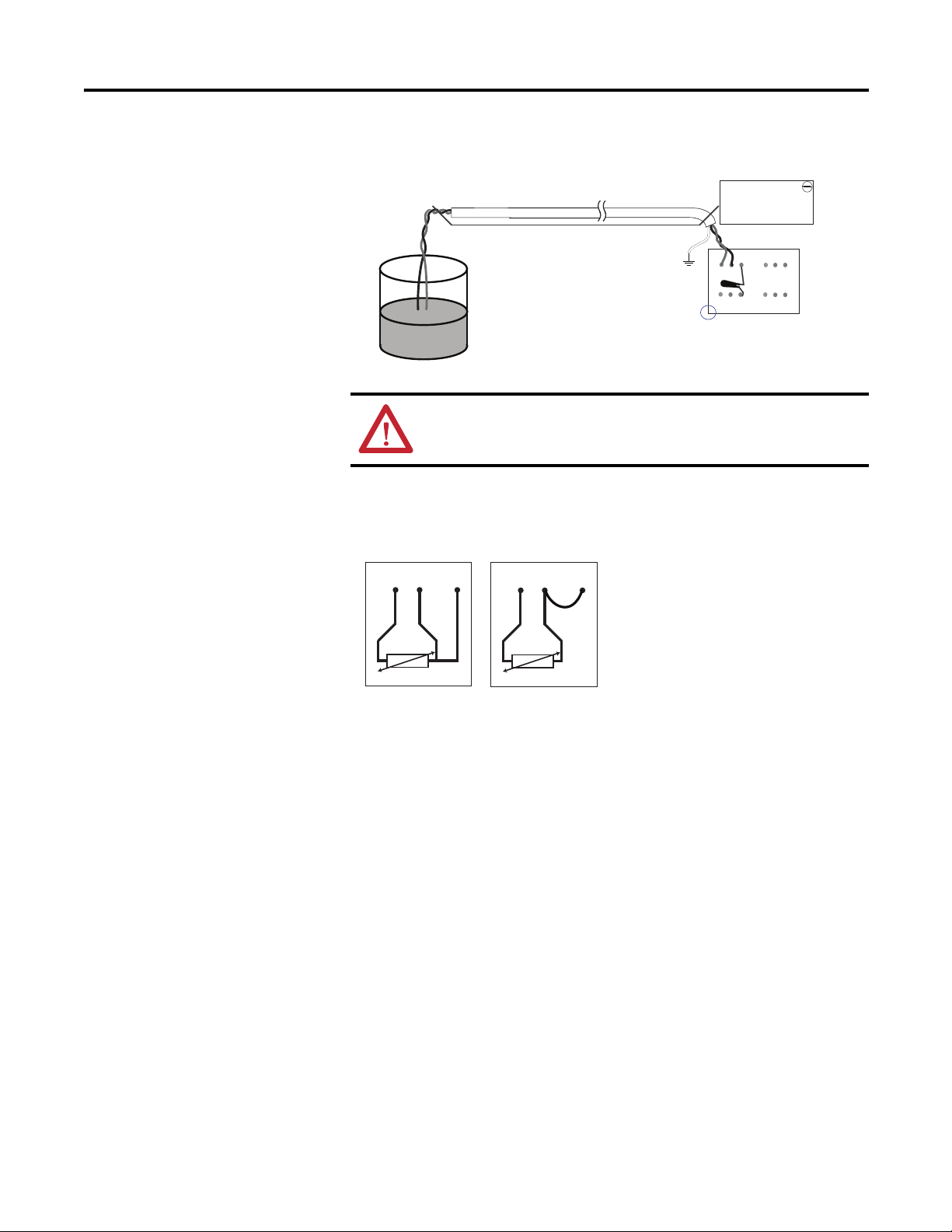
Direct sensor wiring
2080-TC2
1 2 3 4 5 6
1 2 3 4 5 6
Red
Blue
Green
Red
Blue
Process
temperature
measurement
Shielded/sheathed thermocouple sensor
45790
+
-
Cable tray/conduit
3 Wire
2 Wire
45772
ATTENTION: Direct wiring is the preferred method of wiring for
thermocouples.
Install and Wire Your Module Chapter 2
Wiring Considerations and Applications for 2080-RTD2
Two-wire and Three-Wire Wiring
1
23
1
23
Wire the RTD Sensors
In an RTD sensor, the sensing element is always connected between two wires of
different colors. Wires of the same color are shorted and form the compensation
leads. Measuring resistance between these wires confirms the position of sensing
element and compensation elements. Compensation elements will always show
0ohms.
Rockwell Automation Publication 2080-UM004C-EN-E - March 2015 13
Page 22
Chapter 2 Install and Wire Your Module
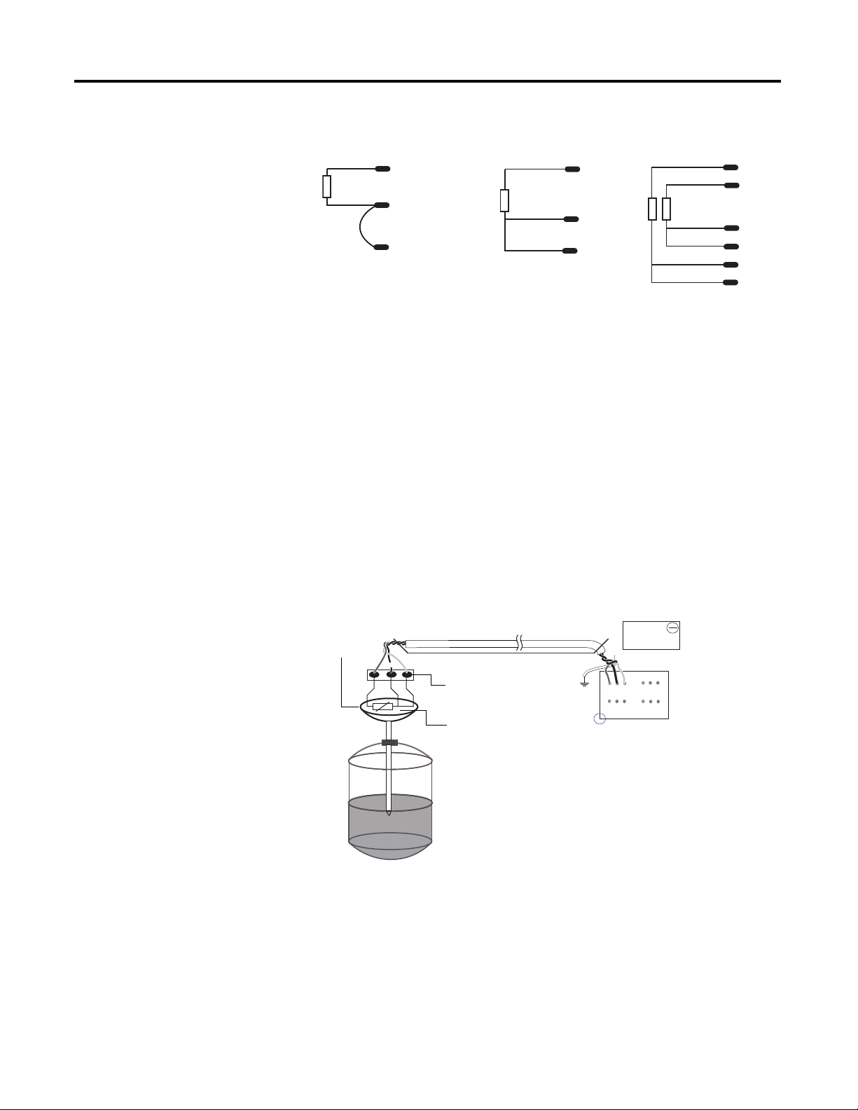
white
red
Ch0+
Ch0-
Ch0L
white
red
red
green
black
black
white
red
red
Ch1+
Ch1Ch1L
Ch0Ch0L
Ch0+
Ch0-
Ch0L
Ch0+
2-wire sensor
connection
3-wire single
sensor connection
3-wire dual
sensor connection
45778
NOTE: This illustration provides for channel 0 only for 2- and 3wire single sensor connections. The wire colors illustrate a
particular type of RTD sensor available in market.
Process
temperature
Measurement
Shielded twisted wire cable
Field screw
junction box
3-wire
RTD
Oil filled
thermowell
45779
3-wire RTD shown
Cable tray/conduit
Wire the Sensors
For better accuracy in noisy industrial environments, 3- or 4-wire RTD sensors
are mostly used. While using these sensors, the resistance added by lead lengths is
compensated by an additional third wire in case of 3-wire RTD and two
additional wires, in bridge configuration, in case of 4-wire RTD. For 2-wire RTD
sensor in this module, this lead compensation is provided by using an external
50 mm 22 AWG shorting wire between terminals A2, A3 and B2, B3 for channel
0 and 1, respectively. Shielded twisted pair cables are to be utilized for remote use
of these sensors with cable shield grounded at controller end.
Wire the RTD Module and RTD Sensor in the Field
2080-RTD2
Red
Black
Blue
2
1
3
The RTD sensing element should always be connected between terminals B1(+)
14 Rockwell Automation Publication 2080-UM004C-EN-E - March 2015
and B2(-) for channel 1, and A1(+) and A2(-) for channel 0 in the module.
Terminals B3 and A3 should always be shorted to B2 and A2, respectively, to
complete the constant current loop. Mismatch in wiring can cause erroneous,
over, or underrange readings.
Black
Blue
B
1 2 3 4 5 6
1 2 3 4 5 6
A
Red
Green
Page 23

Install and Wire Your Module Chapter 2
IMPORTANT
Cabling used with the 2080-TC2/RTD2 modules have to be shielded
twisted cores with the shield wire shorted to chassis ground at controller
end. It is advisable to use 22 AWG wires to connect the sensors to the
module. Use sensors dipped in oil-filled thermowells for stable and
uniform readings. Recommended cable type: Alpha wire P/N 5471C.
Performance is dependent on the application. For better noise immunity,
cable length should ideally be less than 10 m because the plug-ins are
non-isolated. For longer cable length requirements, use the 2085
expansion I/O modules instead.
Rockwell Automation Publication 2080-UM004C-EN-E - March 2015 15
Page 24
Chapter 2 Install and Wire Your Module
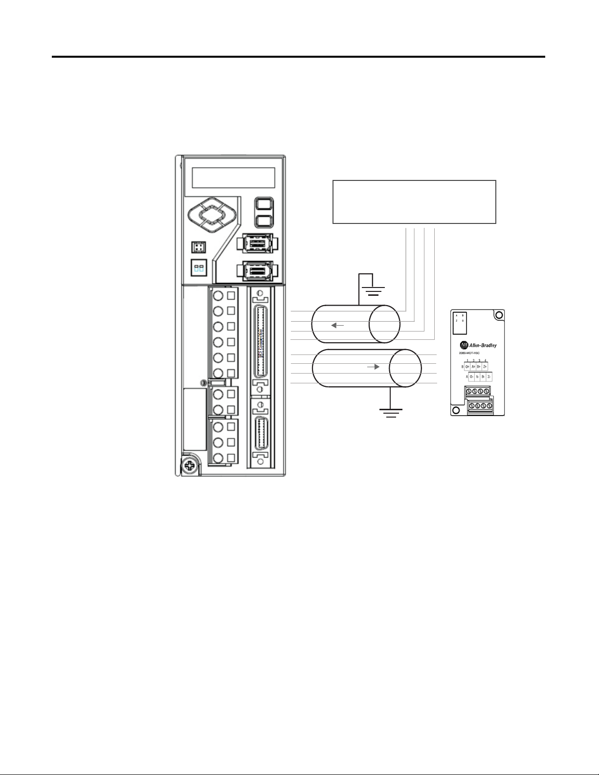
Micro830/Micro850 QBB (24 pts)
PTO
I/O Connector
49 = 24V_PULS+
12 = PLUS14 = SIGN25 = 24V_SIGN+
I/O Connector
29 = AM+
30 = AM31 = BM+
32 = BM-
49
12
14
25
FEEDBACK
A+
AB+
B-
O-00
-CM0
-CM1
O-03
29
30
31
32
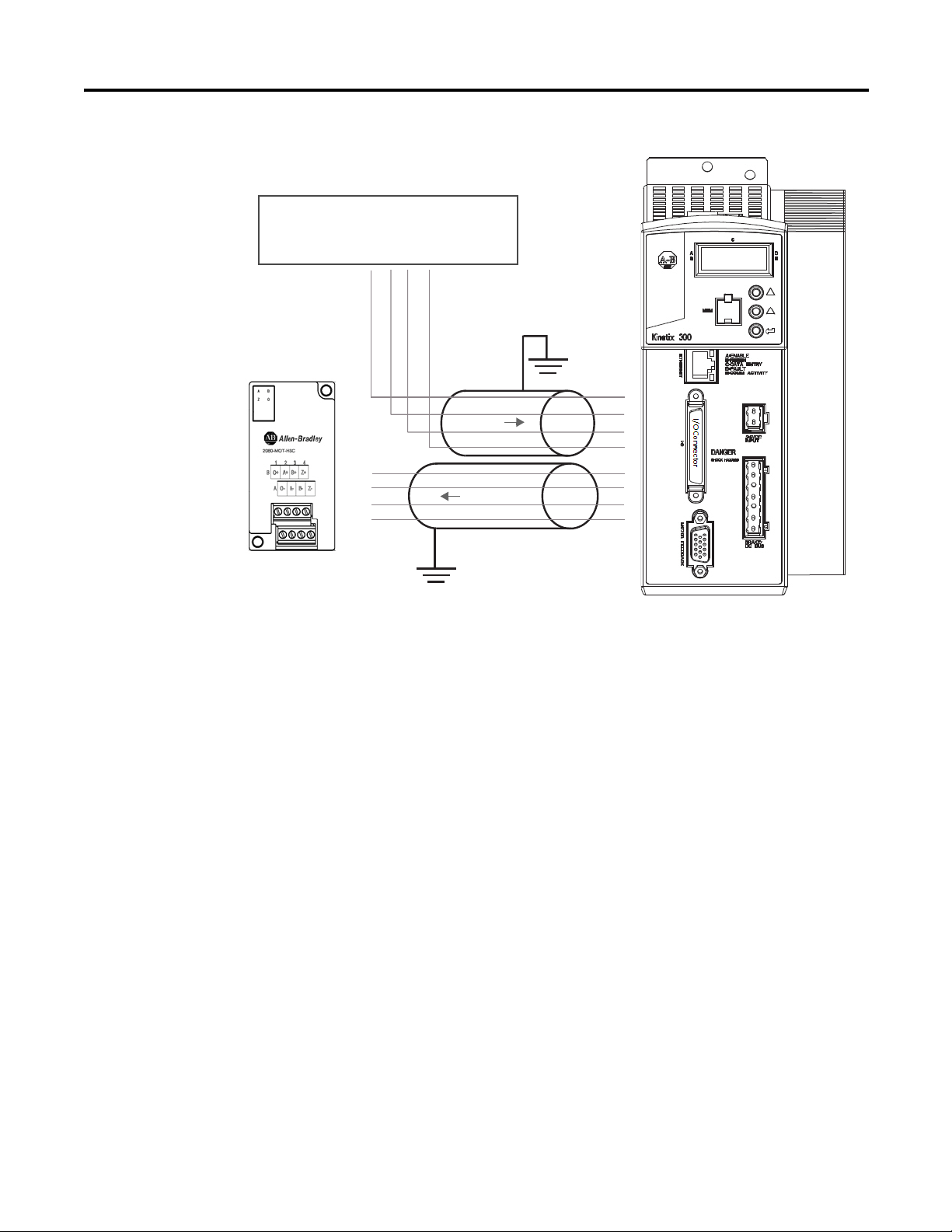
Wiring Applications for 2080-MOT-HSC
The following diagrams show wiring applications for the 2080-MOT-HSC
plug-in with Kinetix® Servo drives.
Kinetix 3 in feedback configuration to 2080-MOT-HSC
Kinetix 300 in feedback configuration to 2080-MOT-HSC
16 Rockwell Automation Publication 2080-UM004C-EN-E - March 2015
Page 25
Install and Wire Your Module Chapter 2
Micro830/Micro850 QBB (24 pts)
PTO
I/O Connector
49 = 24V_PULS+
12 = PLUS14 = SIGN-
25 = 24V_SIGN+
I/O Connector
29 = AM+
30 = AM31 = BM+
32 = BM-
1
2
3
4
FEEDBACK
A+
AB+
B-
O-00
-CM0
-CM1
O-03
7
8
9
10
Rockwell Automation Publication 2080-UM004C-EN-E - March 2015 17
Page 26

Chapter 2 Install and Wire Your Module
Notes:
18 Rockwell Automation Publication 2080-UM004C-EN-E - March 2015
Page 27

Chapter
3
Non-isolated Thermocouple and RTD
Plug-in Modules – 2080-TC2 and 2080-RTD2
The Thermocouple (2080-TC2) and RTD (2080-RTD2) plug-in modules allow
for temperature measure and control when used with PID.
This plug-in can be used in any slot of your Micro830/Micro850 controller.
Removal and Insertion Under Power (RIUP) is not supported.
Thermocouple Module
The 2080-TC2 two-channel plug-in module supports thermocouple measurement.
It digitally converts and transmits temperature data from any combination of up to
eight types of thermocouple sensors. Each input channel is individually configurable
through the Connected Components Workbench software for a specific sensor,
filter frequency.
Thermocouple Sensor Types and Ranges
The module supports B, E, J, K, N, R, S, T types of thermocouple sensors. The
module channels are referred to as Channel 0, Channel 1, and CJC, respectively.
The cold junction compensation is provided by an external NTC thermistor,
which comes with the module. The thermistor has to be fitted to the screw
terminals A3 and B3 of the module. This CJC is common to channel 0 and 1
thermocouple sensors and provides open-circuit, overrange and underrange
detection and indication.
Overrange and Underrange Conditions
If the channel temperature input is below the minimum value of its normal
temperature range for the represented sensor, the module reports an underrange
error through the Connected Components Workbench global variables. If the
channel reads above the maximum value of its normal temperature range for the
represented sensor, an over-range error is flagged.
The table below defines thermocouple types and their associated full-scale
temperature ranges.
Rockwell Automation Publication 2080-UM004C-EN-E - March 2015 19
Page 28

Appendix 3 Non-isolated Thermocouple and RTD Plug-in Modules – 2080-TC2 and 2080-RTD2
Thermocouple Sensor Types and Temperature Ranges
Thermocouple
Ty pe
B 40 (104) 1820
E -270 (-454) 1000
J -210 (-346) 1200
K -270 (-454) 1370
N -270 (-454) 1300
R -50 (-58) 1760
S -50 (-58) 1760
T -270 (-454) 400
Temperature Range
° C (°F)
Min Max ±1.0 °C ±3.0 °C
(3308)
(1832)
(2192)
(2498)
(2372)
(3200)
(3200)
(752)
90…1700
(194…3092)
-200…930
(-328…1706)
-130…1100
(-202…2012)
-200…1300
(-328…2372)
-200…1200
(-328…2192)
40…1640
(104…2984)
40…1640
(104…2984)
-220…340
(-364…644)
Accuracy
° C (°F)
< 90 (194)
> 1700 (3092)
< -200 (-328)
> 930 (1706)
< -130 (-202)
> 1100 (2012)
< -200 (-328)
> 1300 (2372)
< -200 (-328)
> 1200 (2192)
< 40 (104)
> 1640 (2984)
< 40 (104)
> 1640 (2984)
< -220 (-364)
> 340 (644)
ADC Update
Rate in Hz
(Accuracy °C)
4.17, 6.25, 10, 16.7
(±1.0)
19.6, 33, 50, 62,
123, 242, 470 (±3.0)
To configure Thermocouple type and update rate in Connected Components
Workbench software, refer to the section Quickstart
on page 79.
RTD Module
The 2080-RTD2 module supports RTD measurement applications that support
up to two channels. The module digitally converts analog data and transmits the
converted data in its image table.
The module supports connections from any combination of up to eleven types of
RTD sensors. Each channel is individually configurable through the Connected
Components Workbench software. When configured for RTD inputs, the module
can convert the RTD readings into temperature data. Refer to
Conversion – Data to Degree Celsius (°C) on page 23
, for converting temperature
Te m p e r a t u r e
data to actual temperature degree.
RTD Sensor Types and Ranges
Each channel provides open-circuit (all wires), short-circuit (excitation and
return wires only), and over- and under-range detection and indication. The
2080-RTD2 module supports 11 types of RTD sensors:
Pt100 385 PT1000 385 PT500 392 Ni120 672
PT200 385 PT100 392 PT1000 392 NiFe604 518
PT500 385 PT200 392 Cu10 427
20 Rockwell Automation Publication 2080-UM004C-EN-E - March 2015
Page 29

Non-isolated Thermocouple and RTD Plug-in Modules – 2080-TC2 and 2080-RTD2 Appendix 3
It supports two- and three-wire type of RTD sensor wiring.
RTD Compatibility
An RTD consists of a temperature-sensing element connected by two, three, or
four wires that provide resistance input to the module. The following table lists
the RTD types that you can use with the module, including their temperature
range, accuracy, and ADC update rate.
Overrange and Underrange Conditions
If the channel temperature input is below the minimum value of its normal
temperature range for the represented sensor, the module reports an underrange
error through the Connected Components Workbench global variables. If the
channel temperature input is above the maximum value of its normal temperature
range for the represented sensor, an over-range error is flagged.
RTD Sensor Types and Temperature Ranges
RTD Type Temperature
PT100 385 -200
PT200 385 -200
PT500 385 -200
PT1000 385 -200
PT100 392 -200
PT200 392 -200
PT500 392 -200
PT1000 392 -50
Cu10 427
Ni120 672 -80
NiFe604 518 -200
(1)
Range ° C (°F)
Min Max ±1.0 °C ±3.0 °C
(-328)
(-328)
(-328)
(-328)
(-328)
(-328)
(-328)
(-58)
-100
(-148)
(-112)
(-328)
660
(1220)
630
(1166)
630
(1166)
630
(1166)
660
(1220)
630
(1166)
630
(1166)
500
(932)
260
(500)
260
(500)
200
(392)
Accuracy ° C (°F) ADC Update
-150…590
(-238…1094)
-150…570
(-238…1058)
-150…580
(-238…1076)
-150…570
(-238…1058)
-150…590
(-238…1094)
-150…570
(-238…1058)
-150…580
(-238…1076)
-20…450
(-4…842)
-50…220
(-58…428)
-170…170
(-274…338)
< -150 (-238)
> 590 (1094)
< -150 (-238)
> 570 (1058)
< -150 (-238)
> 580 (1076)
< -150 (-238)
> 570 (1058)
< -150 (-238)
> 590 (1094)
< -150 (-238)
> 570 (1058)
< -150 (-238)
> 580 (1076)
< - 20 (-4)
> 450 (842)
< -70 (-94)
> 220 (428)
< -50 (-58)
> 220 (428)
< -170 (-274)
> 170 (338)
Rate in Hz
(Accuracy °C)
3-wire others
4.17, 6.25, 10, 16.7,19.6,
33, 50 (±1.0)
62, 123, 242, 470 (±3.0)
2- and 3-wire Cu10
4.17, 6.25, 10, 16.7
(>±1.0 < ±3.0)
19.6, 33, 50, 62, 123, 242,
470 (> ±3.0)
2-wire others
4.17, 6.25, 10, 16.7 (±1.0)
19.6, 33, 50, 62, 123, 242,
470 (±3.0)
(1)
(1) For Cu10 427, accuracy range is within >±1.0 < ±3.0 for -70…220 °C (-94…428 °F). Above this temperature
range, it is > ±3.0 °C as shown in the table.
Rockwell Automation Publication 2080-UM004C-EN-E - March 2015 21
Page 30

Appendix 3 Non-isolated Thermocouple and RTD Plug-in Modules – 2080-TC2 and 2080-RTD2
Connected Components
Workbench Global
The following bit/words describe the information read from the Thermocouple
and RTD plug-in modules in the Connected Components Workbench Global
Vari ab le s.
Variables
Data Maps
Mapping Table
Word Offset Bit
15 14 13 12 11 10 09 08 07 06 05 04 03 02 01 00
00 (example: _IO_P1_AI_00) Channel 0 Temperature Data 01 (example: _IO_P1_AI_01) Channel 1 Temperature Data 02 (example: _IO_P1_AI_02) Channel 0 Information
UKT UKR Reserved Reserved OR UR OC DI CC Reserved
03 (example: _IO_P1_AI_03) Channel 1 Information
UKT UKR Reserved Reserved OR UR OC DI CC Reserved
04 (example: _IO_P1_AI_04) System Information
Reserved SOR SUR COC CE Reserved
Bit Definitions
Bit Name Description
Channel Temperature Data The temperature count mapped from temperature Celsius degree
UKT (Unknown Type) Bit set to report an unknown sensor type error in configuration.
UKR (Unknown Rate) Bit set to report an unknown update rate error in configuration.
OR (Overrange) Bit set to indicate overrange on channel input. The Channel
UR (Underrange) Bit set to indicate the channel input underrange happens. The
OC (Open Circuit) Bit set to indicate open-circuit on the channel input sensor.
DI (Data Illegal) The data in the channel data field is illegal and cannot be used
CC (Code Calibrated) Bit set indicates temperature data is calibrated by the system
SOR (System Overrange) Bit set to indicate system overrange error with environment
SUR (System Underrange) Bit set to indicate system underrange error with environment
COC (CJC open-circuit) Bit set to indicate CJC sensor not connected for thermocouple
CE (Calibration Error) Bit set indicates that the module is not accurate. This bit is set to
with one decimal. Please check the section, Temperature
Conversion – Data to Degree Celsius (°C) on page 23, for the
mapping formula.
Temperature Data shows maximum temperature count for
individual type of sensor used and the value does not change
until overrange error is clear.
Channel Temperature Data will show minimum temperature
count for individual type of sensor used and the value does not
change until underrange error is clear.
by user. This bit is set when temperature data is not ready for
use.
calibration coefficient.
temperature over 70 °C.
temperature under -20 °C.
module, open circuit. This bit is for thermocouple module only.
0 by default and should remain as 0. Contact Technical Support
when the value is otherwise.
22 Rockwell Automation Publication 2080-UM004C-EN-E - March 2015
Page 31

Non-isolated Thermocouple and RTD Plug-in Modules – 2080-TC2 and 2080-RTD2 Appendix 3
IMPORTANT
IMPORTANT
Temperature Conversion – Data to Degree Celsius (°C)
To keep the precision of temperature value from the Thermocouple and RTD
plug-in modules, there is a general data mapping conversion in the firmware
before the actual temperature is sent to the Connected Components Workbench
software.
The following equation shows how the Connected Components Workbench
software data count is mapped from temperature Celsius degree by the firmware:
Connected Components Workbench software Data Count = (Temp (°C) +
270.0)*10;
This conversion formula applies to all types of Thermocouple and
RTD sensors.
This equation illustrates how the Connected Components Workbench data
count does not use full range of 0…65535 of data word.
Derive Actual Temperature °C From Connected Components Workbench Data Count:
The following formula shows how to derive temperature Celsius degree from
temperature data word in the Connected Components Workbench software:
Temp (°C) = (Data - 2700)/10;
Examples:
1234 → (1234 - 2700)/10 → -146.6 °C
8000 → (8000 - 2700)/10 → 530.0°C
Underrange, overrange error reporting checking is not based on
Connected Components Workbench temperature data count, but the
actual temperature (°C) or the voltage going into the plug-in
module.
Rockwell Automation Publication 2080-UM004C-EN-E - March 2015 23
Page 32

Appendix 3 Non-isolated Thermocouple and RTD Plug-in Modules – 2080-TC2 and 2080-RTD2
Notes:
24 Rockwell Automation Publication 2080-UM004C-EN-E - March 2015
Page 33

High Speed Counter – 2080-MOT-HSC
IMPORTANT
IMPORTANT
Chapter
4
Overview
The 2080-MOT-HSC plug-in module provides enhanced high speed counter
capabilities to the Micro800 controller. It supports the same functionalities of an
embedded high-speed counter on the Micro800 controllers but is enhanced to
support up to 250 KHz 5V differential line driver for improved noise immunity
and provides additional dedicated I/O.
The 2080-MOT-HSC module supports most commercial encoders (5V
differential or 24V single-ended).
To configure the plug-in module, you need to download and use the
HSC UDFBs from the Sample Code Library:
http://www.rockwellautomation.com/go/scmicro800
From Connected Components Workbench Release 7.0 onwards, the
sample code is included in the installation and is located in the folder:
\documents\public documents\ccw\samples\rockwell automation\udfb
See Quickstart Projects for 2080-MOT-HSC Plug-in
step-by-step instructions on how to use the plug-in with a sample
project.
From Connected Components Workbench Release 8.0 onwards,
support has been added for a HSC Feedback Axis which uses the
same instructions as the PTO Motion Axis. UDFBs are still supported
(you can use either one but you cannot select both for the same plugin).
on page 93 for
Counter Specifications
Filter and decode inputs: 3 input points A, B, Z
These input points may come from different types and configurations of sensors.
The user must configure the module to respond to the type of sensor connected
to the module as described below. This can be configured in the 2080-MOTHSC UDFB. From Connected Components Workbench Release 8.0 onwards, if
you have configured the plug-in for Feedback Axis, you can also edit the input
filter values in the plug-in configuration module properties.
Nominal Filter Settings Maximum Guaranteed
Block Pulse Width
No Filter – Default – –
250 kHz (DC 2 μs) 512 kHz (DC 0.95 μs) 265kHz (DC 1.9 μs)
200 kHz (DC 2.5 μs) 333 kHz (DC 1.5 μs) 201 kHz (DC 2.48 μs)
Rockwell Automation Publication 2080-UM004C-EN-E - March 2015 25
Minimum Guaranteed Pass
Pulse Width
Page 34

Appendix 4 High Speed Counter – 2080-MOT-HSC
IMPORTANT
IMPORTANT
A
B
Z
Counter
HSC_Mode = 2 to 11
A
Z
Counter
HSC_Mode = 0, 1, 12, and 13
Counter
B
Nominal Filter Settings Maximum Guaranteed
Block Pulse Width
80 kHz (DC 6.25 μs) 128 kHz (DC 3.9 μs) 86.7 kHz (DC 5.8 μs)
40 kHz (DC 12.5 μs) 62.8 kHz (DC 8.0 μs) 42.5 kHz (DC 11.6 μs)
13.3 kHz (DC 35 μs) 20.8 kHz (DC 24.1 μs) 14.1 kHz (DC 35.5 μs)
10 kHz (DC 50 μs) 15.7 kHz (DC 32.1 μs) 10.5 kHz (DC 47.2 μs)
4 kHz (DC 125 μs) 6.3 kHz (DC 80.3 μs) 4.2 kHz (DC 119 μs)
2 kHz (DC 250 μs) 3.2 kHz (DC 161 μs) 2.1 kHz (DC 237 μs)
1 kHz (DC 0.5 ms) 1.6 kHz (DC 0.33 ms) 1.0 kHz (DC 0.48 ms)
500 Hz (DC 1 ms) 778 Hz (DC 0.65 ms) 527 Hz (DC 0.95 ms)
250 Hz (DC 2 ms) 389 Hz (DC 1.3 ms) 263 Hz (DC 1.9 ms)
125 Hz (DC 4 ms) 195 Hz (DC 2.6 ms) 131 Hz (DC 3.79 ms)
62.5 Hz (DC 8 ms) 97.3 Hz (DC 5.2 ms) 65.9 Hz (DC 7.6 ms)
31.25 Hz (DC 16 ms) 38.8 Hz (DC 10.3 ms) 32.9 Hz (DC 15.2 ms)
Minimum Guaranteed Pass
Pulse Width
For low frequency pulses, filter times should be set appropriately to
avoid extra pulses from a noisy environment. For high frequency
pulses, shielded cable must always be used.
When the controller is power cycled, the value of the counters are
reset to zero.
The counters are not reset to zero for program download. For
example, if using the feedback axis, use the MC_ResetPosition
function block to reset the position to zero.
Number of Counters: 1 to 2
The module may be configured, using HSC_Mode, to use the inputs as 1 or 2
counters.
1 counter: A, B, Z = Counter 0
2 counters: A, Z = Counter0; B = Counter 1
Counter Pin Usage
26 Rockwell Automation Publication 2080-UM004C-EN-E - March 2015
Page 35

High Speed Counter – 2080-MOT-HSC Appendix 4
Input A
Input B
Input Z
Encoder or Sensor
Increment Pulse
(count up)
1
2
3
4
5
6
7
8
Counter 0
(Input A)
PresentCount 1
Encoder or Sensor
Increment Pulse
(count up)
Input Operational Modes
Mode Description
0 Up Counter – The accumulator is immediately cleared (0) when it reaches the high
1 Up Counter with external reset and hold – The accumulator is immediately cleared (0)
2 Counter with external direction.
3 Counter with external direction, reset, and hold.
4 Two input counter (up and down).
5 Two input counter (up and down) with external reset and hold.
6 Quadrature counter (phased inputs A and B).
7 Quadrature counter (phased inputs A and B) with external reset and hold.
8 Quadrature X4 counter (phased inputs A and B).
9 Quadrature X4 counter (phased inputs A and B) with external reset and hold.
10 Quadrature X2 counter (phased inputs A and B).
11 Quadrature X2 counter (phased inputs A and B) with external reset and hold.
12 Down Counter.
13 Down Counter with external reset and hold.
preset. A low preset cannot be defined in this mode.
when it reaches the high preset. A low preset cannot be defined in this mode.
Up Counter
Pulses on A will cause the up counter (Counter 0). Also Pulses on B will cause the
up counter (Counter 1).
Rockwell Automation Publication 2080-UM004C-EN-E - March 2015 27
Page 36

Appendix 4 High Speed Counter – 2080-MOT-HSC
INPUT A
INPUT B
INPUT Z
Direction control
Count pulse
Incrementing Encoder or Sensor
Sensor or Switch
Count Pulse
(Input A)
Direction Control
(Input B)
Present Count
1
2
3
2
1
0
1
2
Counter with External Direction
Pulses on A cause the counter to increment when B is low and decrement when B
is high. When B is open or undriven, the counter will increment. See Pulse
External Direction Counting on page 28.
Pulse External Direction Counting
A B Change in Count Value
1 X (don’t care) 0
0 X (don’t care) 0
Two input counter (Up/Down Pulses)
Pulses on A causes the counter to increment. Pulses on B causes the counter to
decrement. Pulses may occur at any time. Note that pulses can occur very closely
(that is, much faster than plug-in scan time) that the plug-in never notices the
change in count. In such cases, both counts may be ignored (the net change being
zero anyway). In no case shall a pulse be lost. See the following diagram.
0 (Open or No Connection) +1
1-1
28 Rockwell Automation Publication 2080-UM004C-EN-E - March 2015
Page 37

High Speed Counter – 2080-MOT-HSC Appendix 4
INPUT A
INPUT B
INPUT Z
Increment Pulse
(Input A)
Count Pulse
(Input A)
1
2
3
2
1
0 0
1
Increment Pulse
(count up)
Decrement Pulse
(count down)
Incrementing
Encoder or Sensor
Decrementing
Encoder or Sensor
Present Count
Up/Down Counting
A B Change in Count Value
0 or 1 +1
0 or 1 -1
0
00 0
Quadrature Counter (X1)
The module is compatible with 2 and 3 signal quadrature, or incremental
encoders. The A and B signals are offset by 90 degrees and encode the direction of
the rotation. The third signal, Z, occurs once per revolution and is often used as a
home reference. The module’s use of this signal is discussed below in the Z input
section.
Rockwell Automation Publication 2080-UM004C-EN-E - March 2015 29
Page 38

Appendix 4 High Speed Counter – 2080-MOT-HSC
INPUT A
INPUT B
INPUT Z
Quadrature
Encoder
A
B
X1
Count
X2
Count
1
2
3
4
5
6
7
8
9
10
11
12
11
10
9
8
7
6
5
4
3
2
1
0
Quadrature Counting
Quadrature X4 Counter
Counter shall increment or decrement on each edge of the A and B pulses when
the signal is in the positive or negative direction respectively. See previous
illustration.
Quadrature X2 Counter
The counter increments or decrements on each edge of the A pulse when the
signal is in the positive or negative direction respectively. See previous illustration.
Down Counter
Pulses on A will cause the down counter (Counter 0). Also pulses on B will cause
the down counter (Counter 1).
30 Rockwell Automation Publication 2080-UM004C-EN-E - March 2015
Page 39

Down Counting
INPUT A
INPUT B
INPUT Z
Decrement Pulse
(count down)
Decrement Pulse
(count down)
Encoder or Sensor
Encoder or Sensor
-1
-2
-3
-4
-5
-6 -7
-8
-1
-2
-3
-4
-5
-6
-7
-8
Counter 0
(Input A)
PresentCount 1
Counter 0
(Input B)
PresentCount 2
IMPORTANT
High Speed Counter – 2080-MOT-HSC Appendix 4
Z Input (Gate) Function/Touch Probe
This signal functionality supports:
• Tou ch Pr ob e the present count value on the rising edge of IntZ_n to the
HSC_Touch Probe term in the backplane input file.
• Hold the counter at its present count value while IntZ_n = 1,
• Reset the present count value on rising edge of IntZ_n.
If the module gets two or more Z pulses during a single plug-in scan the
HSC_TouchProbe will be overwritten with the last stored value. There
will be no indication that more than one store has occurred.
Ring or Linear Counter
The counter may be configured with the RingOrLinearCnt_n control bit to
rollover at its limits (ring counter) or to stop counting and set a flag (linear
counter).
0: ring counter. When the counter is a ring counter and the present count value
is equal to MaxCountValue_n, the next input count in the up direction will cause
the PresentCount_n to become the MinCountValue_n. This action is known as
rollover. And the CountOverflow_n flag will be set to indicate that a rollover has
happened. It is reset using the ResetCountOverflow bit.
Rockwell Automation Publication 2080-UM004C-EN-E - March 2015 31
Conversely, when the PresentCount_n is equal to MinCountValue_n the next
input count in the down direction will cause the PresentCount_n to become the
MaxCountValue_n. This action is known as rollunder. The CountUnderflow_n
Page 40

Appendix 4 High Speed Counter – 2080-MOT-HSC
IMPORTANT
Rollover
MinCountValue
MaxCountValue
Count Up
Count Down
flag will be set to indicate that a rollunder has occurred. It is reset using the
ResetCountUnderflow_n bit.
1: linear counter. When the counter is a linear counter and the present count
value is equal to MaxCountValue_n the next input count in the up direction will
activate the CountOverflow_n bit and also the PresentCount_n will remain at
the MaxCountValue_n. CountOverflow_n is reset using the
ResetCountOverflow_n bit.
Conversely, when the PresentCount_n is equal to MinCountValue_n the next
input count in the down direction will activate the CountUnderflow_n bit and
the PresentCount_n will remain at MinCountValue_n. CountUnderflow_n is
reset using the ResetCountUnderflow_n bit.
The counts in overflow and underflow will not be accumulated at all.
That is, even if 1000 pulses are applied while in overflow, the first pulse
with the opposite direction (down in this case) will cause the counter to
be decremented by 1. (The CountOverflow_n bit is only reset using the
ResetCountUnderflow_n bit.)
32 Rockwell Automation Publication 2080-UM004C-EN-E - March 2015
Page 41

High Speed Counter – 2080-MOT-HSC Appendix 4
MinCountValue
MaxCountValue
Underflow
Overflow
Count Down
Count Up
0
Enabling and Disabling a Counter using the HSC_EN bit
Disabling the counter does not inhibit any HSC_ACC_Bn loading functions
(preset or direct write) or any Z function.
The module continuously calculates rates for each of the counters regardless of
input operational mode.
Timer
For the first two counters, a timer is used to measure the time between two
successive pulses. This value is reported to the backplane as
HSC_PULSE_WIDTH_Bn.
Understanding Rates
There are different applications which require rate information but there is no
one perfect method for all. Generally, the user must weigh rate accuracy with the
need for new information quickly.
Broadly, there are two different ways to calculate rates and optimize accuracy and
speed of the rate of calculation:
• Per Pulse
1/HSC_PULSE_WIDTH_B (supported through 2080-MOT-HSC
plug-in)
HSC_PULSE_WIDTH_Bn is reported to the user in the input array
• Cyclic
Number of Pulses/User Defined Time Interval (supported through
Connected Components Workbench)
PresentRate_n is reported to the user in the input array.
Rockwell Automation Publication 2080-UM004C-EN-E - March 2015 33
Page 42

Appendix 4 High Speed Counter – 2080-MOT-HSC
1 ms
1 ms
1 ms
1
2
3
4
1
2
1000 Hz
2000 Hz
1
1000 Hz
PresentCount_n
⌂Count
PresentRate_n
0
Per Pulse
The Per Pulse rate method can be very accurate if the time between pulses is large
compared to the timer clock (1 μs for 2080-MOT-HSC). A timer is used to
measure the time between the two successive pulses. This value is reported to the
backplane as HSC_PULSE_WIDTH_Bn after each pulse. The user may invert
this value to derive a rate.
Per Pulse rate = 1 / HSC_PULSE_WIDTH_B
However, when the time between pulses shrinks, two factors can distort the Per
Pulse calculation of rate values:
• The time between pulses is closer to measuring the clock’s frequency,
making the granularity of the time increments have a greater effect on rate
inaccuracy.
• Also, the rate may be calculated many times over during the course of one
backplane scan time. This means that the rate data is obtained at a
backplane scan is only that of the very last pair of pulses and disregards the
other rate calculations that have happened during that interval. This is
especially problematic if the pulses during the update time are unevenly
spaced, the reported rate could be based entirely on two pulses which are
extremely close together (a very high rate) but a third pulse was separated
by a greater time (low rate).
You must understand these limitations when using HSC_PULSE_WIDTH_Bn
to derive a rate.
Per Pulse Errors
Real pulses
(note 1.9999 can
be rounded to 2)
2 1 500 kHz 1 MHz 100%
9 10 111 kHz 100 kHz 11.1%
101 100 9.901 kHz 10.000 kHz 1.00%
(1)
Pulses
reported by
module
Real
Frequency
Reported
Frequency
% Error
34 Rockwell Automation Publication 2080-UM004C-EN-E - March 2015
Page 43

High Speed Counter – 2080-MOT-HSC Appendix 4
IMPORTANT
RA_HSCPlugIn
FBEN
SlotID
NoiseFilter
Mode
FBENO
IDCheck
Start
Stop
Initialized
Accumulator
Rate
Per Pulse Errors
Real pulses
(note 1.9999 can
be rounded to 2)
(1)
Pulses
reported by
module
Real
Frequency
Reported
Frequency
% Error
1001 1000 999 Hz 1000 Hz 0.10%
9,999 10,000 100.01 Hz 100.00 Hz 0.010%
99,999 100,000 10.00010 Hz 10.00000 Hz 0.001%
(1) This table does not represent accuracy per pulse but repeatability. This repeatability can be applied in No
Filter setting.
Maximum Cyclic Rate Errors
Update Time
Value Scalar
1 NA NA 20.02% 20.02% 0.210%
10 NA 20.11% 2.020% 0.210% 0.030%
100 20.01% 2.110% 0.220% 0.031% 0.012%
1000 3.010% 0.310% 0.040% 0.013% 0.010%
10,000 1.210% 0.130% 0.022% 0.011% 0.010%
Frequency
100 Hz 1 kHz 10 kHz 100 kHz 1 MHz
For low frequency pulses, filter times should be set appropriately to
avoid extra pulses from a noisy environment. For high frequency pulses,
shielded cable must always be used.
User Defined Function
RA_HSCPlugIn
Blocks
The purpose of this UDFB is to get high speed counter accumulator value and
current pulse frequency.
Rockwell Automation Publication 2080-UM004C-EN-E - March 2015 35
Page 44

Appendix 4 High Speed Counter – 2080-MOT-HSC
RA_EncoderFDBK
FBEN
SlotID
HomePos
NoiseFilter
FBENO
IDCheck
EncMode
TrvPerRev
Initialized
CurrentPOS
CurrentSpd
Start
Stop
Accumulator
TpPosition
Direction
RA_HSCPlugIn: Input and Output Parameters
Parameter Type Data Type Description
FBEN INPUT BOOL Function block Enable input
SlotID INPUT UINT Plug-in slot number.
Slot ID = 1…5 (starting with the far left slot 1.)
NoiseFilter INPUT USINT 00: No filter
01: 250 kHz
02: 200 kHz
03: 80 kHz
04: 40 kHz
05: 13.3 kHz
06: 10 kHz
07: 4 kHz
08: 2 kHz
09: 1 kHz
10: 500 Hz
11: 250 Hz
12: 125 Hz
13: 63.5 Hz
14: 31.25 Hz
HSCMode INPUT USINT 0, 2 , 4, 6, 8, 10, 12
Start INPUT BOOL Start counter.
Stop INPUT BOOL Stop the counter and clear “MaxDPos” and
“MaxDSpd” value.
FBENO OUTPUT BOOL Function block Enable output.
IDCHeck OUTPUT BOOL TRUE: HSC plug-in is at selected slot.
FALSE: Wrong plug-in or no plug-in at selected slot.
Initialized OUTPUT BOOL TRUE: HSC plug-in initialization finished and ready
to execute.
FALSE: HSCplug-in initialization not yet finished.
Accumulator OUTPUT LINT Accumulator value.
Rate OUTPUT Real Current pulse rate. The rate calculation is based on
how many pulses have been counted every 10 ms.
RA_EncoderFDBK
RA_EncoderFDBK: Input and Output Parameters
Parameter Type Data
Ty pe
FBEN INPUT BOOL Function block Enable input
SlotID INPUT UINT Plug-in slot number.
HomePos INPUT REAL Home position.
36 Rockwell Automation Publication 2080-UM004C-EN-E - March 2015
Description
Slot ID = 1…5 (starting with the far left slot 1)
Same value indicated in MC_Home instruction.
Page 45

High Speed Counter – 2080-MOT-HSC Appendix 4
RA_ServoFDBK
FBEN
SlotID
HomePos
NoiseFilter
FBENO
IDCheck
EcntPerRev
TrvPerRev
Initialized
CurrentPOS
CurrentSpd
Start
Stop
Accumulator
TpPosition
Direction
RA_EncoderFDBK: Input and Output Parameters
Parameter Type Data
Description
Ty pe
NoiseFilter INPUT USINT 00 - No filter
01 - 250 kHz
02 - 200 kHz
03 - 80 kHz
04 - 40 kHz
05 - 13.3 kHz
06 - 10 kHz
07 - 4 kHz
08 - 2 kHz
09 - 1 kHz
10 - 500 Hz
11 - 250 Hz
12 - 125 Hz
13 - 62.5 Hz
14 - 31.25 Hz
EncMode INPUT USINT Encoder Mode. 1-X1, 2- X2, 4-X4.
ECntPerRev INPUT REAL User input to indicate how many X1 counts will be
generated when Encoder disk turns one revolution.
TrvPerRev INPUT REAL The actual distance travelled when motor turns one
revolution.
Start INPUT BOOL Start counter.
Stop INPUT BOOL Stop the counter and clear MaxDPos and MaxDSpd value
FBENO OUTPUT BOOL Function block enable output.
IDCheck OUTPUT BOOL TRUE: HSC plug-in is at selected slot.
FALSE: Wrong plug-in or no plug-in at selected slot.
Initialized OUTPUT BOOL TRUE: Indicates HSC initialization has finished.
FALSE: Indicates HSC initialization has not finished.
CurrentPos OUTPUT REAL Current position.
CurrentSpd OUTPUT REAL Current speed (Unit = user distance per second).
Accumulator OUTPUT LINT Accumulator value.
TpPosition OUTPUT REAL Position recorded when the latest touch probe is triggered.
Direction OUTPUT SINT 1 = Forward
-1 = Reverse
0 = Not moving
RA_ServoFDBK
RA_ServoFDBK: Input and Output Parameters
Parameter Type Data
Ty pe
FBEN INPUT BOOL Function block Enable input
SlotID INPUT UINT Plug-in slot number.
HomePos INPUT REAL Home position.
Rockwell Automation Publication 2080-UM004C-EN-E - March 2015 37
Description
Slot ID = 1…5 (starting with the far left slot 1)
Same value indicated in MC_Home instruction.
Page 46

Appendix 4 High Speed Counter – 2080-MOT-HSC
RA_ServoFDBK: Input and Output Parameters
Parameter Type Data
Ty pe
NoiseFilter INPUT USINT 00: No filter
EncMode INPUT USINT Encoder Mode. 1-X1, 2- X2, 4-X4.
ECntPerRev INPUT REAL User input to indicate how many X1 counts will be
TrvPerRev INPUT REAL The actual distance travelled when motor turns one
Start INPUT BOOL Start counter.
Stop INPUT BOOL Stop the counter and clear MaxDPos and MaxDSpd value.
FBENO OUTPUT BOOL Function block enable output.
IDCheck OUTPUT BOOL TRUE: HSC plug-in is at selected slot.
Initialized OUTPUT BOOL TRUE: Indicates HSC initialization has finished.
CurrentPos OUTPUT REAL Current position.
CurrentSpd OUTPUT REAL Current speed (Unit = user distance per second).
Accumulator OUTPUT LINT Accumulator value.
TpPosition OUTPUT REAL Position recorded when the latest touch probe is triggered.
Direction OUTPUT SINT 1 = Forward
Description
01: 250 kHz
02: 200 kHz
03: 80 kHz
04: 40 kHz
05: 13.3 kHz
06: 10 kHz
07: 4 kHz
08: 2 kHz
09: 1 kHz
10: 500 Hz
11: 250 Hz
12: 125 Hz
13: 62.5 Hz
14: 31.25 Hz
generated when Encoder disk turns one revolution.
revolution.
FALSE: Wrong plug-in or no plug-in at selected slot.
FALSE: Indicates HSC initialization has not finished.
-1 = Reverse
0 = Not moving
Use the 2080-MOT-HSC Module
For a step-by-step guide on how to use the Micro800 High Speed Counter plugin, see Quickstart Projects for 2080-MOT-HSC Plug-in
38 Rockwell Automation Publication 2080-UM004C-EN-E - March 2015
on page 93.
Page 47

DeviceNet Plug-in – 2080-DNET20
IMPORTANT
IMPORTANT
IMPORTANT
Chapter
5
Overview
The DeviceNet plug-in serves as scanner and client for explicit messaging to
remote devices. The module is designed to scan devices such as:
• CompactBlock™ LDX
• PowerFlex® drives
• E1Plus overloads
• stack lights
User-defined function blocks (UDFB) are required to enable interaction
between these devices.
The 2080-DNET20 DeviceNet scanner supports a maximum of 20 nodes. For
example, if the scanner ID is configured to zero, the scanner would scan from
1…20. It is supported on Micro800 controllers with available plug-in slots. Only
one 2080-DNET20 DeviceNet scanner is supported per controller.
Rockwell Automation recommends that only one 2080-DNET20
DeviceNet scanner be used for each network trunk-line.
If the 2080-DNET20 DeviceNet scanner is control flashed to a new
major firmware version (for example, from 1.xxx to 2.xxx or vice
versa), once the plug-in is successfully upgraded, power cycle the
controller.
If RSLinx browsing is enabled, the CIP client messages can get timed
out because the DeviceNet buffers are fully occupied by RSLinx
messages. It is recommended not to have RSLinx browsing to the
DeviceNet bridge if Client Messaging is required.
Status Indicators
Rockwell Automation Publication 2080-UM004C-EN-E - March 2015 39
The DeviceNet plug-in module supports two standard DeviceNet green and red
LED indicators:
• Module status
• Network status
Page 48

Appendix 5 DeviceNet Plug-in – 2080-DNET20
IMPORTANT
Module Status Indicator
LED state Module status Description
OFF No power There is no power present.
Flashing Green Operational Unit is starting up.
Green Unit operational Device is operating normally.
Flashing Red Minor fault. A recoverable fault is present or the module is
Red Unrecoverable fault. A non-recoverable fault is detected.
Network Status Indicator
LED state Module Status Description
OFF No power or offline There is no network power or device is not operating.
Flashing Green Idle No valid network connection has been made.
Green Online The plug-in module is operating normally and receiving
Flashing Red Connection time out One or more network connections has timed out.
Red Critical link failure The plug-in module has detected an error that makes it
undergoing firmware update.
messages.
incapable of communicating on the link (Bus Off or
duplicate MAC_ID).
Network Configuration
In order to configure the DeviceNet plug-in and scan the network, you need to
import user-defined function blocks (UDFBs) in your Micro800 project in
Connected Components Workbench. Autoscan is used to add nodes into the
scan list.
It is recommended that when Autoscan is running for the nodes in
range, or for the connection to be established, the nodes should be idle
without any pre-occupied connections requests.
Network Wiring
The DeviceNet specifications provide for maximum network distances for the
main trunk line and drop lines, depending upon the baud rate used on the
network.
Network Specifications
Baud Rate Trunk Line Length Drop Length
Maximum Distance Maximum Cumulative
Meters Feet Meters Feet Meters Feet
125k baud 420 1377 6 20 156 512
250k baud 200 656.17 6 20 78 256
500k baud 75 246 6 20 39 128
40 Rockwell Automation Publication 2080-UM004C-EN-E - March 2015
Page 49

IMPORTANT
TIP
ON
1
23
4
5
7
6
8
Dim A
Pos. 1 Designate
Pin #1 Location
1
35
7 9 11 13
15
246
8
10
12
14
16
CONTACT CONFIGURATION
(Pos. 1 denotes Pin # 1)
Maximum power supply drop cable length is 3 m.
Recommended Cable
Flat Cable (Kwiklink lite)
– Class 1 cable maximum allowable current 8A (NEC/CECode)
– Class 2 cable maximum allowable current 4A (NEC/CECode)
DeviceNet Switches
2080-DNET20 Assembly Diagram
DeviceNet Plug-in – 2080-DNET20 Appendix 5
DeviceNet Address (MAC_ID) Switch Definitions
Node Address SW1 Switch Positions
345678
Switch Position Values
32168421
0 (default) OFF OFF OFF OFF OFF OFF
1 OFF OFF OFF OFF OFF ON
2 OFF OFF OFF OFF ON OFF
3 OFF OFF OFF OFF ON ON
4 OFF OFF OFF ON OFF OFF
5 OFF OFF OFF ON OFF ON
…
62 ON ON ON ON ON OFF
63 ON ON ON ON ON ON
Rockwell Automation Publication 2080-UM004C-EN-E - March 2015 41
Page 50

Appendix 5 DeviceNet Plug-in – 2080-DNET20
IMPORTANT
DeviceNet Baud Rate Switch Definitions
Baud Rate DR (Data Rate) SW1 Switch Position
12
125k OFF OFF
250k OFF ON
500k (default) ON OFF
Autobaud ON ON
For most applications, Rockwell Automation recommends that you use
default node and baud rate settings. The DeviceNet scanner plug-in will
be at node 0 and the devices will be at nodes 1...20. The baud rate will
be at 500k baud and the maximum trunkline length will be 75 m
(KwikLink Lite).
Power Supply
The plug-in module gets its power from the Micro800 backplane. However, the
DeviceNet interface is isolated from the Micro800 system. Therefore, network
power to operate the DeviceNet transceiver on the plug-in module is supplied by
an external DeviceNet power supply.
If using a single power supply in the network, calculate the total current
requirement of all devices in the network and add +10% for current surge.
Recommended power supply is 1606-XLSDNET4.
Power Supply Cable Dropline Length
Dropline Length Allowable Current
1.5 m (5 ft) 3 A
2 m (6 ft) 2 A
3 m (10 ft) 1.5 A
4.5 m (15 ft) 1 A
6 m (20 ft) 0.75 A
42 Rockwell Automation Publication 2080-UM004C-EN-E - March 2015
Page 51

DeviceNet Plug-in – 2080-DNET20 Appendix 5
VPower Supply
V+
CAN_H
CAN_L
VV+
V+ broken between
power supplies
only one ground
VPower Supply
V+
Enclosure
TIP
Single Source Power Supply (End segment) Kwiklink Lite Cable
9.00
8.00
7.00
6.00
5.00
4.00
3.00
2.00
1.00
0.00
0 (0)
60
(197)
120
(394)
180
(591)
240
(787)
300
(984)
360
(1181)
420
(1378)
If two or more power supplies are connected to the Kwinklink lite media (trunk
cable) V+ should be broken between the two power supplies.
Grounding the network
If grounding at only one location, it is recommended that you ground at the
center of the network.
Rockwell Automation Publication 2080-UM004C-EN-E - March 2015 43
Single Source Power Supply – Trunkline Length and Maximum Current
Network Length
in meter (ft)
0 (0) 8.00
20 (66) 8.00
40 (131) 7.01
60 (197) 4.72
80 (262) 3.56 300 (984) 0.96
100 (238) 2.86 320 (1050) 0.90
Current, max Network Length
in meter (ft)
(1)
(1)
(1)
(1)
220(722) 1.31
240 (787) 1.20
260 (853) 1.11
280 (919) 1.03
Current, max
Page 52

Appendix 5 DeviceNet Plug-in – 2080-DNET20
Dual Source Power Supply (both ends – Kwiklink Lite Cable)
9.00
8.00
7.00
6.00
5.00
4.00
3.00
2.00
1.00
0.00
0 (0)
40
(131)
80
(262)
120
(394)
160
(525)
200
(656)
240
(787)
280
(919)
320
(1050)
360
(1181)
400
(1312)
Single Source Power Supply – Trunkline Length and Maximum Current
120 (394) 2.39 340 (1115) 0.85
140 (459) 2.05 360 (1181) 0.80
160 (525) 1.79 380 (1247) 0.76
180 (591) 1.60 400 (1312) 0.72
200 (656) 1.44 420 (1378) 0.69
(1) Exceeds NEC CL2/CECode 4A limit.
Dual source power supply (both ends – Kwiklink Lite Cable)
Network length
in meters (ft)
0 (0) 8.00
20 (66) 8.00 240 (787) 4.30
40 (131) 8.00 260 (853) 3.97
60 (197) 8.00 280 (919) 3.69
80 (262) 8.00 300 (984) 3.44
100 (328) 8.00 320 (1050) 3.23
120 (394) 8.00 340 (1115) 3.04
140 (459) 7.35 360 (1181) 2.87
160 (525) 6.43 380 (1247) 2.72
180 (591) 5.72 400 (1312) 2.59
200 (656) 5.16 420 (1378) 2.46
(1) Exceeds NEC CL2/CECode 4A limit.
Current, max Network length
in meters (ft)
(1)
220 (722) 4.69
Current, max
44 Rockwell Automation Publication 2080-UM004C-EN-E - March 2015
Page 53

DeviceNet Plug-in – 2080-DNET20 Appendix 5
IMPORTANT
Calculate Voltage Requirement
SUM {[(Ln * (Rc)) + (Nt * (0.005))] * In} < 4.65 V
Where:
Ln = Length in meter or feet
Rc = Resistance of the cable per meter or feet
(Kwiklink flat media = 0.019 ohms/meter or 0.0058/feet)
Nt = Number of the node starting from 1 close to power supply and increasing.
0.005 = Nominal contact resistance used for every connection to the trunkline
In = Current drawn from the cable system by the device.
To calculate for percentage of loading, divide the total voltage
calculated from the above formula by 4.65.
User Defined Function Blocks
RA_DNET_MASTER
FBEN
SlotID
Run
AutoScan
ClearFault
FBENO
NodeAddress
BaudRate
Status
Error
ActiveNodes
ScanList0_62
Download the following 2080-DNET20 user-defined function blocks from the
Sample Code Library:
http://www.rockwellautomation.com/go/scmicro800
RA_DNET_MASTER
This UDFB sets the 2080-DNET20 scanner to RUN mode.
RA_DNET_MASTER: Input and Output Parameters
Variable Name Type Data Type Description
FBEN INPUT BOOL TRUE: To continue reading and writing
SlotID INPUT UINT Plug-in slot number (1…5)
Run INPUT BOOL TRUE: Set the scanner to RUN mode.
AutoScan INPUT BOOL TRUE: AutoScan is enabled.
ClearFault INPUT BOOL TRUE: Clear scanner fault.
FBENO OUTPUT BOOL Function block enable output.
NodeAddress OUTPUT USINT Scanner node address. Default node
BaudRate OUTPUT USINT Network baud rate:
Status OUTPUT USINT Scanner fault status.
the scanner status. FBEN changed to
level Triggered.
FALSE: Scanner is in IDLE mode.
AutoScan is enabled.
FALSE: No action.
TRUE upon exit.
address is 0.
0: 125K
1: 250K
2: 500K
3: AutoBaud
Default baud rate is 500K.
0: No error.
Rockwell Automation Publication 2080-UM004C-EN-E - March 2015 45
Page 54

Appendix 5 DeviceNet Plug-in – 2080-DNET20
FBEN
SlotID
NodeID
FBENO
RA_DNET_NODE_STATUS
Status
Error
RA_DNET_MASTER: Input and Output Parameters
Variable Name Type Data Type Description
Error OUTPUT STRING Scanner error description.
ActiveNodes OUTPUT USINT Number of slave nodes in the network.
Scanlist0_62 OUTPUT LWORD Details on active node table, bit 0…62.
Bit 0: Represent Node 0.
Bit 62: Represent Node 62.
Sequence of Operation: RA_DNET_MASTER
Sequence Run Autoscan Description
1 False False Reinitializes scan list from the plug-in scanner if
FBEN = TRUE.
2 False True Triggers autoscan to scan the network after clearing
scan list.
3 False False Puts scanner to IDLE mode by disabling autoscan if
active node number = number of nodes in network.
4 True False Puts scanner to RUN mode.
Upon powerup, the scanner should be in IDLE Mode for the autoscan to start.
Wait until the autoscan process is complete before turning the scanner to RUN
Mode (that is, Run bit is TRUE).
Sample Code
RA_DNET_NODE_STATUS
This UDFB is used to read the node status of slave nodes in a DeviceNet network
where the 2080-DNET20 scanner is connected.
46 Rockwell Automation Publication 2080-UM004C-EN-E - March 2015
Page 55

DeviceNet Plug-in – 2080-DNET20 Appendix 5
FBEN
SlotID
NodeID
FBENO
RA_DNET_LDX_DISCRETE
DI_Module1
DI_Module2
Module1
Module2
Module3
DO_Module2
DO_Module3
Module4
DO_Module4
DO_Module1
DI_Module3
DI_Module4
RA_DNET_NODE_STATUS: Input and Output Parameters
Variable Name Type Data Type Description
FBEN INPUT BOOL Function block enable input.
TRUE to enable the function.
SlotID INPUT UINT Plug-in slot number (1…5)
NodeID INPUT USINT Slave node address.
FBENO OUTPUT BOOL Function block enable output.
TRUE upon exit.
Status OUTPUT USINT Scanner fault status.
0: No errors.
Error OUTPUT STRING Description of the node status error.
Sample Code: RA_DNET_NODE_STATUS
RA_DNET_LDX_DISCRETE
This UDFB is used for I/O data exchange with discrete CompactBlock I/O.
RA_DNET_LDX_DISCRETE: Input and Output Parameters
Variable Name Type Data Type Description
FBEN INPUT BOOL Function block enable input.
SlotID INPUT UINT Plug-in slot number (1…5)
NodeID INPUT USINT Node address of the digital Compact I/O slave node.
Module1 INPUT STRING Base module I/O configuration.
Module2 INPUT STRING Expansion module 1 I/O configuration.
Rockwell Automation Publication 2080-UM004C-EN-E - March 2015 47
TRUE to enable the function block.
INPUT X OUTPUT Channels
For example: 16X0 (16 input / 0 output is physically
present as base module)
Valid String: 32X0, 0X32, 16X0, 0X16, 16X16, 8X8,
8X0, 0X8, 0X6
NOTE: X should always be upper case.
INPUT X OUTPUT channels
For example: 16X0 (16 input / 0 output is physically
present as base module)
Valid String: 32X0, 0X32, 16X0, 0X16, 16X16, 8X8,
8X0, 0X8, 0X6
NOTE: X should always be upper case.
Page 56

Appendix 5 DeviceNet Plug-in – 2080-DNET20
FBEN
SlotID
NodeID
FBENO
RA_DNET_LDX_ANALOG
AI_CH0
AI_CH1
AI_CH2
AI_CH3
StatusCH0_3
DI_Module2
DI_Module3
Module1
Module2
Module3
AO_Ch0
AO_Ch1
DO_Module2
DO_Module3
RA_DNET_LDX_DISCRETE: Input and Output Parameters
Variable Name Type Data Type Description
Module3 INPUT STRING Expansion module 2 I/O configuration.
INPUT X OUTPUT Channels
For example: 16X0 (16 input / 0 Output is physically
present as base module)
Valid String: 32X0, 0X32, 16X0, 0X16, 16X16, 8X8,
8X0, 0X8, 0X6
NOTE: X should always be upper case.
Module4 INPUT STRING Expansion module 3I/O configuration.
INPUT X OUTPUT Channels
For example: 16X0 (16 input / 0 output is physically
present as base module)
Valid String: 32X0, 0X32, 16X0, 0X16, 16X16, 8X8,
8X0, 0X8, 0X6
NOTE: X should always be upper case.
DO_Module1 INPUT UDINT Output data for base module.
DO_Module2 INPUT UDINT Output data for expansion module 1.
DO_Module3 INPUT UDINT Output data for expansion module 2.
DO_Module4 INPUT UDINT Output data for expansion module 3.
FBENO OUTPUT BOOL Function block enable output.
TRUE upon exit.
DI_Module1 OUTPUT UDINT Input data from base module (Module 1).
DI_Module2 OUTPUT UDINT Input data from expansion module 1
(Module 2).
DI_Module3 OUTPUT UDINT Input data from expansion module 2
(Module 3).
DI_Module4 OUTPUT UDINT Input data from expansion module 3
(Module 4).
RA_DNET_LDX_ANALOG
This UDFB is used for data exchange with analog CompactBlock I/O.
RA_DNET_LDX_ANALOG: Input and Output Parameters
Variable Name Type Data Type Description
FBEN INPUT BOOL Function block enable input.
SlotID INPUT UINT Plug-in slot number (1…5)
NodeID INPUT USINT Slave node address.
(1)
Module1
Module2
(1)
INPUT STRING Analog base module I/O configuration.
INPUT STRING Digital expansion module 1 I/O configuration.
48 Rockwell Automation Publication 2080-UM004C-EN-E - March 2015
TRUE to enable the function.
INPUT X OUTPUT Channels
For example: 4X0 (4 input analog module is
physically present as base module)
Valid String: 0X2, 4X0
NOTE: X should always be upper case.
INPUT X OUTPUT Channels
For example: 16X16 (16 input / 16 output is
physically present as expansion module 1)
Valid String: 16X0, 0X16, 16X16, 8X8, 8X0, 0X8, 0X6
NOTE: X should always be upper case.
Page 57

DeviceNet Plug-in – 2080-DNET20 Appendix 5
FBEN
SlotID
NodeID
FBENO
CH0
CH1
CH2
CH3
StatusCH0_3
RA_DNET_LDX_TC_RTD
RA_DNET_LDX_ANALOG: Input and Output Parameters
Variable Name Type Data Type Description
(1)
Module3
AO_Ch0 INPUT WORD Analog Output Channel 0 value.
AO_Ch0 INPUT WORD Analog Output Channel 1 value.
DO_Module2 INPUT UINT Output data for Expansion Module 1.
DO_Module3 INPUT UINT Output Data for Expansion Module 2.
FBENO OUTPUT BOOL Function block enable output.
AI_CH0 OUTPUT WORD Analog Input Channel 0 value.
AI_CH1 OUTPUT WORD Analog Input Channel 1 value.
AI_CH2 OUTPUT WORD Analog Input Channel 2 value.
AI_CH3 OUTPUT WORD Analog Input Channel 3 Value.
StatusCH0_3 OUTPUT WORD Analog input channel 0…3 status
DI_Module2 OUTPUT UINT Digital Expansion Module 1 Input Data.
DI_Module3 OUTPUT UINT Digital Expansion Module 2 Input Data.
INPUT STRING Digital expansion module 2 I/O configuration.
INPUT X OUTPUT channels
For example: 16X16 (16 input / 16 output is
physically present as expansion module 2)
Valid String: 16X0, 0X16, 16X16, 8X8, 8X0, 0X8, 0X6
NOTE: X should always be upper case.
This value is valid only if Module1 = '0X2'
This value is valid only if Module1 = '0X2'
TRUE upon exit.
This value is valid only if Module1 = '4X0'
This value is valid only if Module1 = '4X0'
This value is valid only if Module1 = '4X0'
This value is valid only if Module1 = '4X0'
Applicable only if catalog is with digital inputs.
Applicable only if catalog is with digital inputs.
(1) Use only valid strings combinations as mentioned above. If Module1, Module2, Module3 physical I/O does not
match the physical I/O present in base and expansion, then incorrect sequence will be written.
RA_DNET_LDX_TC_RTD
This UDFB is used to read input data from the Thermocouple/RTD module.
RA_DNET_LDX_TC_RTD: Input and Output Parameters
Variable Name Type Data Type Description
FBEN INPUT BOOL Function block enable input.
SlotID INPUT UINT Plug-in slot number (1…5)
NodeID INPUT USINT Node address of the digital Compact I/O slave node.
FBENO OUTPUT BOOL Function block enable output.
CH0 OUTPUT WORD RTD/Thermocouple input channel 0 value.
CH1 OUTPUT WORD RTD/Thermocouple input channel 1 value.
Rockwell Automation Publication 2080-UM004C-EN-E - March 2015 49
TRUE to enable function.
Page 58

Appendix 5 DeviceNet Plug-in – 2080-DNET20
FBEN
PlcPortNum
Start
Stop
ReferenceSpeed
Jog
ClearFault
Fwd_Rev
FBENO
RA_PF_DNET_STANDARD
DriveNodeNum
Status
PF_Feedback
PF_ErrorCode
PF_Ready
PF_Active
PF_Alarm
PF_Fault
PF_AltReference
RA_DNET_LDX_TC_RTD: Input and Output Parameters
Variable Name Type Data Type Description
CH2 OUTPUT WORD RTD/Thermocouple input channel 2 value.
CH3 OUTPUT WORD RTD/Thermocouple input channel 3 value.
StatusCH0_3 OUTPUT WORD RTD/Thermocouple Input channel 0…3 status.
RA_DNET_TOWERLIGHT
FBEN
SlotID
NodeID
Light_0_4
FBENO
Status_0_4
RA_DNET_TOWERLIGHT
This UDFB is used for data exchange with a towerlight or stacklight.
RA_DNET_TOWERLIGHT: Input and Output Parameters
Variable Name Type Data Type Description
FBEN INPUT BOOL Function block enable input.
SlotID INPUT UINT Plug-in slot number (1…5)
NodeID INPUT USINT Towerlight node address.
Light_0_4 INPUT USINT Light 0…4, for example:
FBENO OUTPUT BOOL Function block enable output.
Status_0_4 OUTPUT USINT Light 0…4 status.
TRUE to enable the function.
Bit 0: Blue
Bit 1: Yellow
Bit 2: Red
TRUE upon exit.
RA_PF_DNET_STANDARD
This UDFB is used for I/O data exchange with standard PowerFlex drives
configured as single mode.
RA_PF_DNET_STANDARD: Input and Output Parameters
Variable Name Type Data Type Description
FBEN INPUT BOOL Function block enable input.
PlcPortNum INPUT UINT Plug-in slot number (1…5 for plug-in slots).
DriveNodeNum INPUT USINT Slave node address for PowerFlex drive.
Start INPUT BOOL TRUE to start PowerFlex drive.
Stop INPUT BOOL TRUE to stop PowerFlex drive.
ReferenceSpeed INPUT REAL Reference speed for the device.
Jog INPUT BOOL TRUE to enable jog in PowerFlex drive.
ClearFault INPUT BOOL TRUE to clear fault in PowerFlex drive.
Fwd_Rev INPUT BOOL TRUE to configure PowerFlex drive for forward motion.
50 Rockwell Automation Publication 2080-UM004C-EN-E - March 2015
FBENO OUTPUT BOOL Function block enable output.
TRUE to enable the function.
Configure PowerFlex drive speed.
FALSE to configure PowerFlex drive for reverse motion.
TRUE upon exit.
Page 59

DeviceNet Plug-in – 2080-DNET20 Appendix 5
IMPORTANT
RA_PFDNET_MULTIDRIVE
FBEN
PlcPortNum
NodeNum
Start
Stop
ReferenceSpeed
Jog
ClearFault
Fwd_Rev
FBENO
PF_Feedback
PF_Ready
PF_Active
PF_Alarm
PF_Fault
PF_AltReference
RA_PF_DNET_STANDARD: Input and Output Parameters
Variable Name Type Data Type Description
Status OUTPUT BOOL PowerFlex drive status.
PF_Feedback OUTPUT REAL Feedback from the PowerFlex drive.
PF_ErrorCode OUTPUT INT For future use.
PF_Ready OUTPUT BOOL Ready bit from PowerFlex drive.
PF_Active OUTPUT BOOL Active bit from PowerFlex drive.
PF_Alarm OUTPUT BOOL Alarm bit from PowerFlex drive.
PF_Fault OUTPUT BOOL Fault bit from PowerFlex drive.
PF_AltReference OUTPUT BOOL Alt Reference bit from PowerFlex drive.
Ensure that your PowerFlex drives settings are correct. For basic setup
configuration, see the PowerFlex drives user manuals in the
Rockwell Automation Literature Library
.
With PowerFlex 523, you need to multiply the speed reference and divide the
speed feedback by a factor of 10.0 in order to get the correct value. Note that the
PowerFlex 4 and PowerFlex 5 drives have a different multiplier.
Reference and Feedback for the Different PowerFlex Drives
Drive Type Number Reference Feedback
PowerFlex 4M 132 x10 x0.1
PowerFlex 4 39 x10 x0.1
PowerFlex 40 40 x100 x0.1
PowerFlex 40P 41 x100 x0.01
PowerFlex 400 129 x100 x0.01
PowerFlex 523 8 x100 x0.01
PowerFlex 525 9 x100 x0.01
For example, if you set reference speed at 50, command speed is 50 Hz for
PowerFlex 4M and only 5 Hz for PowerFlex 523 and PowerFlex 525.
RA_PF_DNET_MULTIDRIVE
This UDFB is used for I/O data exchange with standard PowerFlex drives,
configured as multi-drive.
Rockwell Automation Publication 2080-UM004C-EN-E - March 2015 51
Page 60

Appendix 5 DeviceNet Plug-in – 2080-DNET20
RA_PF_DNET_MULTIDRIVE: Input and Output Parameters
Variable Name Type Data Type Description
FBEN INPUT BOOL Function block enable input.
TRUE to enable the function.
PlcPortNum INPUT UINT Plug-in slot number (1…5 for plug-in slots).
NodeNum INPUT USINT DeviceNet node address for PowerFlex drive
(connected as master in multi-drive setup).
Start INPUT BOOL[1…5] TRUE to start each element of the array.
Corresponds to each drive.
For example: Start[1] for Drive 1 and Start[5] for
Drive5.
Stop INPUT BOOL[1…5] TRUE to stop each element of the array.
Corresponds to each drive, for example, Stop
[1] for Drive 1 and Stop [5] for Drive5.
ReferenceSpeed INPUT REA[1...5]L Reference speed to set the device speed.
Each element of the array corresponds to each
drive, for example, Reference Speed [1]
for Drive 1 and Reference Speed [5] for Drive5.
Jog INPUT BOOL[1...5] TRUE to enable jog in PowerFlex drive.
Each element of the array corresponds to each
drive, for example, Reference Jog [1] for Drive
1 and Jog [5] for Drive5.
ClearFault INPUT BOOL[1...5] TRUE to clear fault in PowerFlex drive.
Each element of the array corresponds to each
drive, for example, ClearFault [1] for Drive 1
and ClearFault [5] for Drive5.
Fwd_Rev INPUT BOOL[1...5] TRUE to configure PowerFlex drive for forward
motion.
FALSE to configure PowerFlex drive for Reverse
motion.
Each element of the array corresponds to each
drive, for example, Fwd_Rev [1] for Drive 1 and
Fwd_Rev [5] for Drive5.
FBENO OUTPUT BOOL Function block enable output.
TRUE upon exit.
PF_Feedback OUTPUT REAL[1...5] Speed reference from the PowerFlex drive.
Each element of the array corresponds to each
drive, for example, PF_Feedback[1] for Drive 1
and PF_Feedback[5] for Drive5.
PF_Ready OUTPUT BOOL[1...5] Ready bit from PowerFlex drive.
Each element of the array corresponds to each
drive, for example, PF_Ready[1] for Drive 1 and
PF_Ready[5] for Drive5.
PF_Active OUTPUT BOOL[1...5] Active bit from PowerFlex drive.
Each element of the array corresponds to each
drive, for example, PF_Active[1] for Drive 1 and
PF_Active[5] for Drive5.
52 Rockwell Automation Publication 2080-UM004C-EN-E - March 2015
Page 61

DeviceNet Plug-in – 2080-DNET20 Appendix 5
IMPORTANT
RA_DNET_OVERLOAD
FBEN
SlotID
NodeID
OutA
TripReset
FBENO
IN1
IN2
Warning
Tripped
AverageFLA
ThernUtilized
OutAStart
RA_DNET_GENERIC
FBEN
SlotID
NodeID
OutputData
FBENO
InputData
RA_PF_DNET_MULTIDRIVE: Input and Output Parameters
Variable Name Type Data Type Description
PF_Alarm OUTPUT BOOL[1...5] Alarm bit from PowerFlex drive.
Each element of the array corresponds to each
drive, for example, PF_Alarm[1] for Drive 1 and
PF_Alarm[5] for Drive5.
PF_Fault OUTPUT BOOL[1...5] Fault bit from PowerFlex drive.
Each element of the array corresponds to each
drive, for example, PF_Fault[1] for Drive 1 and
PF_Fault[5] for Drive5.
PF_AltReference OUTPUT BOOL[1...5] Alt Reference bit from PowerFlex drive.
Each element of the array corresponds to each
drive, for example, PF_AltReference[1] for
Drive 1 and PF_AltReference[5] for Drive5.
Ensure that your PowerFlex drives settings are correct. For basic setup
configuration, see the PowerFlex drives user manuals in the
Rockwell Automation Literature Library
.
RA_DNET_OVERLOAD
This UDFB is used for I/O data exchange with an overload relay.
RA_DNET_OVERLOAD: Input and Output Parameters
Variable Name Type Data Type Description
FBEN INPUT BOOL Function block enable input.
SlotID INPUT UINT Plug-in slot number (1…5 for plug-in slots).
NodeID INPUT USINT DeviceNet node address of the slave node.
OutA INPUT BOOL TRUE to turn on Output A.
TripReset INPUT BOOL TRUE to enable Trip Reset.
FBENO OUTPUT BOOL Function block enable output.
IN1 OUTPUT BOOL Input 1 from overload relay.
IN2 OUTPUT BOOL Input 2 from overload relay.
Warning OUTPUT BOOL TRUE if warning is enabled.
Tripped OUTPUT BOOL TRUE if tripped.
AverageFLA OUTPUT WORD Average FLA % value from overload relay.
ThermUtilized OUTPUT WORD Therm Utilized value from overload relay.
OutAStatus OUTPUT WORD Average FLA value from overload relay.
TRUE to enable the function.
TRUE upon exit.
RA_DNET_GENERIC
Rockwell Automation Publication 2080-UM004C-EN-E - March 2015 53
This UDFB is used for I/O data exchange with generic I/O devices.
Page 62

Appendix 5 DeviceNet Plug-in – 2080-DNET20
IMPORTANT
RA_DNET_EXPLICIT
FBEN
SlotID
NodeID
CnxnNumber
FBENO
InputData
MsgLength
CIPService
CIPClass
CIPInstance
CIPAttribute
Q
ResponseData
Status
RequestData
RA_DNET_GENERIC: Input and Output Parameters
Variable Name Type Data Type Description
FBEN INPUT BOOL Function block enable input.
TRUE to enable function.
SlotID INPUT UINT Plug-in slot number (1…5 for plug-in slots).
NodeID INPUT USINT Slave node address.
OutputData INPUT USINT[1…64] Slave output data.
FBENO OUTPUT BOOL Function block enable output.
TRUE to enable function.
InputData[1…64] OUTPUT USINT[1…64] Input data from slave.
RA_DNET_EXPLICIT
This UDFB is used for sending explicit message to slave node.
For DNET explicit message, the maximum payload supported is 256
bytes.
RA_DNET_EXPLICIT: Input and Output Parameters
Variable Name Type Data Type Description
FBEN INPUT BOOL Function block enable input.
SlotID INPUT UINT Plug-in slot number (1…5 for plug-in slots).
NodeID INPUT USINT Node address of slave node.
CnxnNumber INPUT USINT Connection number values 1, 2, 3, 4, 5.
MsgLength INPUT USINT Specifies the size of the CIP message in the
CIPService INPUT UINT CIP service code.
CIPClass INPUT UINT CIP Class code (valid values 0…65535).
CIPInstance INPUT UINT CIP instance (valid values 0…65535).
CIPAttribute INPUT UINT CIP attribute (valid values 0…65535).
RequestData INPUT USINT[1…54] Request data from slave.
FBENO OUTPUT BOOL Function block enable output.
Q OUTPUT BOOL TRUE when message is sent out successfully.
Error OUTPUT BOOL TRUE when message transmits error.
ResponseData OUTPUT USINT
[1...50]
TRUE to enable function.
transaction block.
CIP Response error
Response Data[1] : Extended Error ID
Response Data[2] : Error ID
See Explicit Message Request Format
on
page 55.
See Explicit Message Status Codes on page 55.
Status OUTPUT USINT See Explicit Message Status Codes on page 55.
54 Rockwell Automation Publication 2080-UM004C-EN-E - March 2015
Page 63

Transaction Block Format
Byte Offset Contents
0Status
1 Transaction ID
2Size
3 Reserved
4MAC ID
5 Service
6…115 Transaction Body (110 bytes)
Explicit Message Request Format
Byte Offset Contents
0 Status
1 Transaction ID
2Size
3 Reserved
4 MAC ID
5 Service
6…7 Class
8…9 Instance
10…115 Service Data (106 Bytes)
DeviceNet Plug-in – 2080-DNET20 Appendix 5
Explicit Message Response Format
Byte Offset Contents
0 Status
1 Transaction ID
2Size
3Reserved
4MAC ID
5Service
Byte Offset Contents Request Data
0 Status Can be read from UDFB status
6…115 ServiceData Can be read from UDFB response data.
Explicit Message Status Codes
Status Code Description
0 Ignore transaction block (block empty).
Rockwell Automation Publication 2080-UM004C-EN-E - March 2015 55
Response data shows CIP error Code.
Page 64

Appendix 5 DeviceNet Plug-in – 2080-DNET20
Explicit Message Status Codes
1 Transaction completed successfully.
2 Transaction in progress (not ready).
4 Error – node offline
5 Error – DeviceNet port disabled/offline
6 Error – Transaction TXID unknown
7 Error – Duplicate TXID
9 Error – Scanner out of buffers
12 Error – Response data too large for block
14 Error – Invalid size specified
15 Error – Device timed out
16 Block queued.
17 Block allocated
18 Connection in progress
3, 8, 10, 11, 13, 19...255 Reserved
Send Explicit Messages to 2080-DNET20 Plug-in Using Micro800 Pass Through
MSG_CIPGENERIC instruction can be used to send Explicit messages to the
2080-DNET20 plug-in and the Slave nodes on the DeviceNet network.
In MSG_CIPGENERIC, configure the target path as mentioned below:
• To access the plug-in, the format of the target path is “1, Slot number”.
• To access a Slave device through the plug-in, the format of the target path is
“1, Slot number, 2, DeviceNet node address”.
For example, if the 2080-DNET20 plug-in is connected at physical slot 3 and the
Slave device of address 40 is present in the DeviceNet network, then:
• Using MSG_CIPGENERIC to access the plug-in, the target path would
be “1, 3”.
• Using MSG_CIPGENERIC to access the Slave node through the plug-in,
the target path would be “1, 3, 2, 40”.
Note that the number “1” refers to the Virtual backplane port number and “2”
refers to the 2080-DNET20 plug-in's DeviceNet port number. These are fixed
values. The slot number starts from 1 up to the maximum number of slots
physically present in the controller.
When the controller pass through feature is used in the following example:
Micro850 –> Micro820 [192.168.1.100] –> 2080-DNET20 plug-in
[Slot 3] –> Slave device [Node 40]
• Using MSG_CIPGENERIC starting from Micro850 to access the plugin, the target path would be “4, 192.168.1.100, 1, 3”
56 Rockwell Automation Publication 2080-UM004C-EN-E - March 2015
Page 65

DeviceNet Plug-in – 2080-DNET20 Appendix 5
IMPORTANT
• Using MSG_CIPGENERIC starting from Micro850, the Slave device
cannot be accessed because the MSG_CIPGENERIC target path
configuration is limited to a single hop. This path will work if you use a
Logix controller/PC instead of Micro850.
Note that the number “4” refers to the EtherNet/IP port number (for Serial the
port number varies from 2...5. See the controller’s user manual for detailed
information).
To use the controller pass through feature, the following firmware
revisions are required:
• Micro820/Micro830/Micro850 controller firmware revision 8.011 or
higher.
• 2080-DNET20 plug-in firmware revision 2.011 or higher.
Error Codes
DeviceNet plug-in Error Codes and Descriptions
ErrorID Description
0 No errors.
1 Node number not in scanlist.
65 AutoScan active.
70 Scanner failed DUP MAC check.
71 Illegal value in scanlist.
72 Device stopped communicating.
73 Device does not match scanlist.
74 Scanner has detected data overrun.
75 No network traffic detected.
76 No network traffic detected for scanner.
77 Data size returned does not match scanlist.
78 Device on scanlist not active on subnet.
79 Scanner failed to transmit a message.
80 Scanner is in Idle mode operation.
81 Scanner is in fault mode operation.
82 I/O fragment out of sequence.
83 Device refused to be initialized.
84 Device not yet initialized.
85 Incorrect data size upon connection with device.
86 Device/Slave went into Idle.
87 Shared master has not allocated slave.
88 Shared master has not allocated required choices.
89 Keeper download failed.
Rockwell Automation Publication 2080-UM004C-EN-E - March 2015 57
Page 66

Appendix 5 DeviceNet Plug-in – 2080-DNET20
DeviceNet plug-in Error Codes and Descriptions
ErrorID Description
90 User has disabled scanner.
91 Bus Off detected on scanner.
92 No network power detected.
93 CRC failure detected on one or more
configuration blocks.
95 Scanner application program flash is being updated.
96 Port is in test mode.
97 Scanner is halted by user.
98 ESC, overflow, divide or other processor error.
99 Scanner watchdog has timed out.
Use the 2080-DNET20 Plug-in
For a step-by-step guide on how to use the DeviceNet plug-in, see Quickstart
Project for 2080-DNET20 Plug-in on page 88.
58 Rockwell Automation Publication 2080-UM004C-EN-E - March 2015
Page 67

Specifications
Appendix
A
Digital Plug-in Modules
General Specifications – 2080-OB4, 2080-OV4, 2080-IQ4OB4, 2080-IQ4OV4, 2080-IQ4
Attribute Value
Mounting torque 0.2 Nm (1.48 lb-in.)
Status indicators For input or output modules – 4 yellow
Terminal base screw torque 0.22…0.25 Nm (1.95…2.21 lb-in.)
Enclosure type rating None (open-style)
Isolation voltage For input modules
Wire size 1.3... 0.2 mm
Wire category 2 – on signal ports
North American temp code T4
For combination modules – 8 yellow
using a 2.5 mm (0.10 in.) flat-blade screwdriver
50V (continuous), Basic Insulation Type, Inputs to Backplane
Type tested for 60 s @ 720 V DC, Inputs to Backplane
For combination or output modules
50V (continuous), Basic Insulation Type, Inputs to Outputs, I/Os
to Backplane
Type tested for 60 s @ 720 V DC, I/Os to Backplane
2
rated @ 90 °C (194 °F), or greater, insulation max
2 – on power ports
(16...24 AWG) solid or stranded copper wire
Input Specifications – 2080-IQ4, 2080-IQ4OV4, 2080-IQ4OB4
Attribute Value
DC on-state voltage, min 9.0V DC
DC on-state voltage, max 30V DC
DC on-state current, min 2.0 mA @ 9V DC
DC on-state current, nom 3.0 mA @ 24V DC
DC on-state current, max 5.0 mA
DC off-state voltage, max 5V DC
DC off-state current, max 1.5 mA
IEC input compatibility Type 3
Input impedance 0…3V, >4 KΩ
Input filter time ON to OFF 8…10 ms AC/DC
AC on-state voltage, min 10.25V AC (rms)
AC on-state voltage, max 30V AC (rms)
Rockwell Automation Publication 2080-UM004C-EN-E - March 2015 59
3…12V, 3.5 KΩ min
12…30V, >4 KΩ <10 KΩ
Page 68

Appendix A Specifications
Input Specifications – 2080-IQ4, 2080-IQ4OV4, 2080-IQ4OB4
Attribute Value
AC on-state current, min 2.0 mA @ 9V AC (rms)
AC on-state current, max 5.0 mA
AC off-state voltage 3.5V AC (rms)
Output Specifications – 2080-OB4, 2080-OV4, 2080-IQ4OB4, 2080-IQ4OV4
Attribute Value
Power supply voltage 10.8V DC, min
30V DC, max
On-state voltage 10V DC, min
24V DC, nom
30V DC, max
On-state current 5.0 mA @ 10V DC, min
0.5 A max, steady state
2 A surge, 2 s min
Environmental Specifications – 2080-OB4, 2080-OV4, 2080-IQ4OB4,
2080-IQ4OV4, 2080-IQ4
Attribute Value
Temperature, operating IEC60068-2-1 (Test Ad, Operating Cold),
IEC60068-2-2, (Test Bd, Operating Dry Heat),
IEC 60068-2-14 (Test Nb, Operating Thermal Shock):
-20...65 °C (-4…149 °F)
Temperature, surrounding
65 °C (149 °F)
air, max.
Temperature, non-operating IEC60068-2-1 (Test Ad, Operating Cold),
IEC60068-2-2, (Test Bd, Operating Dry Heat),
IEC 60068-2-14 (Test Nb, Operating Thermal Shock):
-40...85 °C (-40…185 °F)
Relative humidity IEC 60068-2-30 (Test Db, Unpackaged Damp Heat):
5…95% noncondensing
Vibration IEC 60068-2-6 (Test Fc, Operating):
2 g @ 10…500 Hz
Shock, operating IEC 60068-2-27 (Test Ea, Unpackaged Shock):
DIN rail mounting: 25 g
Panel mounting: 35 g
Shock, non-operating IEC 60068-2-27 (Test Ea, Unpackaged Shock):
25 g
Emissions CISPR 11:
Group 1, Class A
ESD Immunity IEC 61000-4-2:
4 kV contact discharges
8 kV air discharges
Radiated RF immunity IEC 61000-4-3:
10 V/M with 1 kHz sine-wave 80%AM from 80…2000 MHz
10 V/M with 200 Hz 50% Pulse 100%AM @ 900 MHz
10 V/M with 200 Hz 50% Pulse 100%AM @1890 MHz
10 V/M with 1 kHz sine-wave 80%AM from 2000…2700 MHz
60 Rockwell Automation Publication 2080-UM004C-EN-E - March 2015
Page 69

Specifications Appendix A
Environmental Specifications – 2080-OB4, 2080-OV4, 2080-IQ4OB4,
2080-IQ4OV4, 2080-IQ4
Attribute Value
EFT/B immunity ±2 kV @ 5 kHz on signal ports
Surge transient immunity ±1 kV line-line(DM) and ±2 kV line-earth(CM) on signal ports
Conducted RF immunity 10V rms with 1 kHz sine-wave 80%AM from 150 kHz…80 MHz
Certifications – 2080-OB4, 2080-OV4, 2080-IQ4OB4, 2080-IQ4OV4, 2080-IQ4
Certification (when
product is marked)
(1)
Value
c-UL-us UL Listed Industrial Control Equipment, certified for US and Canada.
See UL File E322657.
UL Listed for Class I, Division 2 Group A,B,C,D Hazardous Locations,
certified for U.S. and Canada. See UL File E334470.
CE European Union 2004/108/EC EMC Directive, compliant with:
EN 61326-1; Meas./Control/Lab., Industrial Requirements
EN 61000-6-2; Industrial Immunity
EN 61000-6-4; Industrial Emissions
EN 61131-2; Programmable Controllers (Clause 8, Zone A & B)
C-Tick Australian Radiocommunications Act, compliant with:
AS/NZS CISPR 11; Industrial Emissions
KC Korean Registration of Broadcasting and Communications
Equipment, compliant with:
Article 58-2 of Radio Waves Act, Clause 3
(1) See the Product Certification link at http://www.rockwellautomation.com/products/certification/
for Declarations of Conformity, Certificates, and other certification details.
General Specifications – 2080-OW4I Digital Relay Output Plug-in Module
Attribute Value
Mounting torque 0.2 Nm (1.48 lb-in.)
Status indicators 4 yellow
Terminal base screw torque, max 0.19 Nm (1.7 lb-in.)
using a 2.5 mm [0.10 in.] flat-blade screwdriver
Wire size 0.05…1.31 mm2 (30…16 AWG) solid copper wire
rated @ 90 °C (194 °F ) insulation max
Enclosure type rating None (open-style)
Isolation voltage 240V (continuous), Reinforce Insulation Type, between
Output Channels and Output channels to Backplane
Type tested for 60 s @ 1480 V AC Outputs to Outputs,
Outputs to Backplane
Insulation stripping length 5 mm
Wiring category 2 – on signal ports
2 – on power ports
Wire type Copper
North American temp code T4
Inrush current <120 mA @ 3.3V
<120 mA @ 24V
Rockwell Automation Publication 2080-UM004C-EN-E - March 2015 61
Page 70

Appendix A Specifications
General Specifications – 2080-OW4I Digital Relay Output Plug-in Module
Attribute Value
Backplane power 3.3 VDC, 38 mA
Output current, resistive 2 A @ 5…30V DC
0.5 A @ 48V DC
0.22 A @ 125V DC
2 A @ 125V AC
2 A @ 240V AC
Output current, inductive 1.0 A steady state @ 5…28V DC
0.93 A steady state @ 30V DC
0.5 A steady state @ 48V DC
0.22 A steady state @ 125V DC
2.0 A steady state, 15 A make @ 125V AC, PF – cos θ = 0.4
2.0 A steady state, 7.5 A make @ 240V AC, PF – cos θ = 0.4
Output power, resistive, max 250 VA for 125V AC resistive loads
480 VA for 240V AC resistive loads
60 VA for 30V DC resistive loads
24 VA for 48V DC resistive loads
27.5 VA for 125V DC resistive loads
Pilot duty rating C300, R150
Minimum load, per point 10 mA
Initial contact resistance of relay, max 30 mΩ
Output delay time, max 10 ms ON or OFF
Relay Contact Ratings (0.35 power factor) – 2080-OW4I
Maximum Volts Amperes Amperes
Continuous
Make Break Make Break
120V AC 15 A 1.5 A 2.0 A 1800 VA 180 VA
240V AC 7.5 A 0.75 A
24V DC 1.0 A 28 VA
125V DC 0.22 A
Environmental Specifications – 2080-OW4I
Attribute Value
Temperature, operating IEC60068-2-1 (Test Ad, Operating Cold),
IEC60068-2-2, (Test Bd, Operating Dry Heat),
IEC 60068-2-14 (Test Nb, Operating Thermal Shock):
-20...65 °C (-4…149 °F)
Temperature, surrounding
65 °C (149 °F)
air, max.
Temperature, non-operating IEC60068-2-1 (Test Ad, Operating Cold),
IEC60068-2-2, (Test Bd, Operating Dry Heat),
IEC 60068-2-14 (Test Nb, Operating Thermal Shock):
-40...85 °C (-40…185 °F)
Relative humidity IEC 60068-2-30 (Test Db, Unpackaged Damp Heat):
5…95% noncondensing
Vibration IEC 60068-2-6 (Test Fc, Operating):
2 g @ 10…500 Hz
Shock, operating IEC 60068-2-27 (Test Ea, Unpackaged Shock):
10 g
Volt-Amperes
62 Rockwell Automation Publication 2080-UM004C-EN-E - March 2015
Page 71

Environmental Specifications – 2080-OW4I
Attribute Value
Shock, non-operating IEC 60068-2-27 (Test Ea, Unpackaged Shock):
ESD Immunity IEC 61000-4-2:
Radiated RF immunity IEC 61000-4-3
EFT/B immunity IEC 61000-4-4:
Surge transient immunity IEC 61000-4-5:
Conducted RF immunity IEC 61000-4-6:
Certifications – 2080-OW4I
DIN rail mounting: 25 g
Panel mounting: 35 g
6kV contact
8 kV air
10 V/M with 1 kHz sine-wave 80%AM from 80…2000 MHz
10 V/M with 200 Hz sine-wave 50% Pulse 100%AM @ 900 MHz
10 V/M with 200 Hz sine-wave 50% Pulse 100%AM @1890 MHz
10 V/M with 1 kHz sine-wave 80%AM from 2000…2700 MHz
±2 kV @ 5 kHz on signal ports
±1 kV line-line(DM) and ±2 kV line-earth(CM) on signal ports
10V rms with 1 kHz sine-wave 80%AM from 150 kHz…80 MHz
Specifications Appendix A
Certification (when
product is marked)
(1)
Value
c-UL-us UL Listed Industrial Control Equipment, certified for US and Canada.
See UL File E322657.
UL Listed for Class I, Division 2 Group A,B,C,D Hazardous Locations,
certified for U.S. and Canada. See UL File E334470.
CE European Union 2004/108/EC EMC Directive, compliant with:
EN 61326-1; Meas./Control/Lab., Industrial Requirements
EN 61000-6-2; Industrial Immunity
EN 61000-6-4; Industrial Emissions
EN 61131-2; Programmable Controllers (Clause 8, Zone A & B)
European Union 2006/95/EC LVD, compliant with:EN 61131-2;
Programmable Controllers (Clause 11)
C-Tick Australian Radiocommunications Act, compliant with:
AS/NZS CISPR 11; Industrial Emissions
KC Korean Registration of Broadcasting and Communications
Equipment, compliant with:
Article 58-2 of Radio Waves Act, Clause 3
(1) See the Product Certification link at http://www.rockwellautomation.com/products/certification/ for
Declarations of Conformity, Certificates, and other certification details.
Rockwell Automation Publication 2080-UM004C-EN-E - March 2015 63
Page 72

Appendix A Specifications
Analog Plug-in Modules
Input Specifications – 2080-IF2, 2080-IF4
Attribute 2080-IF2 2080-IF4
Number of inputs, single ended 2 4
Analog normal operating ranges Voltage: 0…10V DC
Resolution, max. 12 bits unipolar, with software selected option for 50 Hz,
Data range 0…65535
Input impedance Voltage Terminal: > 220K Ω, Current Terminal: 250 Ω
Overall accuracy
(1)
Non-linearity (in percent full scale) ± 0.1%
Repeatability
(2)
Module error over full temperature
range, -20…65°C (-4…149°F)
Input channel configuration Through configuration software or the user program
Field input calibration Not required
Update time 180 ms per enabled channel
Input group to bus isolation No isolation
Channel to channel isloation Non-isolation
Temperature, operating IEC 60068-2-1 (Test Ad, Operating Cold),
Temperature, non-operating IEC 60068-2-1 (Test Ab, Unpackaged Nonoperating Cold),
Relative humidity IEC 60068-2-30 (Test Db, Unpackaged Damp Heat):
Operating altitude 2000 m
Cable length, max. 10 m
Current: 0…20 mA
60 Hz,
250 Hz, 500 Hz
Voltage Terminal: ±1% full scale @ 25°C
Current Terminal: ±1% full scale @ 25°C
± 0.1%
Voltage: ± 1.5%
Current: ± 2.0%
IEC 60068-2-2 (Test Bd, Operating Dry Heat),
IEC 60068-2-14 (Test Nb, Operating Thermal Shock):
-20...65 °C (-4…149 °F)
IEC 60068-2-2 (Test Bb, Unpackaged Nonoperating Dry Heat),
IEC 60068-2-14 (Test Na, Unpackaged Nonoperating Thermal
Shock):
-40...85 °C (-40…185 °F)
5%...95% non-condensing
(1) Includes offset, gain, non-linearity and repeatability error terms.
(2) Repeatability is the ability of the input module to register the same reading in successive measurements for the
same input signal.
Output Specifications – 2080-OF2
Attribute 2080-OF2
Number of outputs, single ended 2
Analog normal operating ranges Voltage: 10V DC
Resolution, max. 12 bits unipolar
Output count range 0…65535
D/A Conversion Rate (all channels), max. 2.5 ms
64 Rockwell Automation Publication 2080-UM004C-EN-E - March 2015
Current: 0…20 mA
Page 73

Specifications Appendix A
Output Specifications – 2080-OF2
Attribute 2080-OF2
Step Response to 63%
(1)
Current Load ln voltage output, max 10 mA
Resistive load on current output 0…500 Ω (includes wire resistance)
Load range on voltage output > 1k Ω @ 10V DC
Max. inductive load
(current outputs)
Max. capacitive load
(voltage outputs)
Overall Accuracy
(2)
Non-linearity (in percent full scale) ± 0.1%
Repeatability
(3)
(in percent full scale) ± 0.1%
Output error over full temperature range,
-20…65°C (-4…149°F)
Open and short-circuit protection Yes
Output overvoltage protection Yes
Input group to bus isolation No isolation
Channel to channel isolation Non-isolation
Temperature, operating IEC 60068-2-1 (Test Ad, Operating Cold),
Temperature, non-operating IEC 60068-2-1 (Test Ab, Unpackaged Nonoperating
Relative humidity IEC 60068-2-30 (Test Db, Unpackaged Damp Heat):
Operating altitude 2000 m
Cable length, max. 10 m
5 ms
0.01 mH
0.1 µF
Voltage Terminal: ±1% full scale @ 25 °C
Current Terminal: ±1% full scale @ 25 °C
Voltage: ± 1.5%
Current: ± 2.0%
IEC 60068-2-2 (Test Bd, Operating Dry Heat),
IEC 60068-2-14 (Test Nb, Operating Thermal Shock):
-20...65 °C (-4…149 °F)
Cold),
IEC 60068-2-2 (Test Bb, Unpackaged Nonoperating Dry
Heat),
IEC 60068-2-14 (Test Na, Unpackaged Nonoperating
Thermal Shock):
-40...85 °C (-40…185 °F)
5…95% non-condensing
(1) Step response is the period of time between when the D/A converter was instructed to go from minimum to full
range until the device is at 63% of full range.
(2) Includes offset, gain, non-linearity and repeatability error terms.
(3) Repeatability is the ability of the output module to reproduce output readings when the same controller value is
applied to it consecutively, under the same conditions and in the same direction.
Rockwell Automation Publication 2080-UM004C-EN-E - March 2015 65
Page 74

Appendix A Specifications
IMPORTANT
Certifications – 2080-IF2, 2080-IF4, 2080-OF2
Specialty Plug-in Modules
Certification (when
product is marked)
(1)
Value
c-UL-us UL Listed Industrial Control Equipment, certified for US and Canada.
See UL File E322657.
UL Listed for Class I, Division 2 Group A,B,C,D Hazardous Locations,
certified for U.S. and Canada. See UL File E334470.
CE European Union 2004/108/EC EMC Directive, compliant with:
EN 61326-1; Meas./Control/Lab., Industrial Requirements
EN 61000-6-2; Industrial Immunity
EN 61000-6-4; Industrial Emissions
EN 61131-2; Programmable Controllers (Clause 8, Zone A & B)
European Union 2006/95/EC LVD, compliant with:
EN 61131-2; Programmable Controllers (Clause 11)
C-Tick Australian Radiocommunications Act, compliant with:
AS/NZS CISPR 11; Industrial Emissions
(1) See the Product Certification link at http://www.rockwellautomation.com/products/certification/ for
Declarations of Conformity, Certificates, and other certification details.
Specifications – 2080-MEMBAK-RTC
Attribute Value
Resolution READ_RTC() 1 s
Accuracy ± 5 sec/month @ 25 °C
± 9 sec/month@ -20…65 °C
Power off Battery — 3.5 years from date of manufacture @ 25…65 °C, 2.5
years from date of manufacture @ 0 °C
Temperature, operating IEC 60068-2-1 (Test Ab, Unpackaged Nonoperating Cold),
IEC 60068-2-2 (Test Bb, Unpackaged Nonoperating Dry Heat),
IEC 60068-2-14 (Test Na, Unpackaged Nonoperating Thermal Shock):
-20...65 °C (-4…149 °F)
Temperature, nonoperating IEC 60068-2-1 (Test Ab, Unpackaged Nonoperating Cold),
IEC 60068-2-2 (Test Bb, Unpackaged Nonoperating Dry Heat),
IEC 60068-2-14 (Test Na, Unpackaged Nonoperating Thermal Shock):
-40...85 °C (-40…185 °F)
Relative humidity IEC 60068-2-30 (Test Db, Unpackaged Damp Heat):
5…95% non-condensing
Altitude, operating 2000 m
Battery life does not include controller ON time. For example, if the
Controller is ON for 16 hours every day for 365 days, if the module starts
being used after 1 year of manufacturing, battery life is 8.5 years (1 year
initial time + 2.5 years of Off time out of 7.5 years).
66 Rockwell Automation Publication 2080-UM004C-EN-E - March 2015
Page 75

Specifications Appendix A
Specifications – 2080-TRIMPOT6
Attribute Value
Data range 0…255
Number of trimpot 6
Temperature, operating IEC 60068-2-1 (Test Ad, Operating Cold),
IEC 60068-2-2 (Test Bd, Operating Dry Heat),
IEC 60068-2-14 (Test Nb, Operating Thermal Shock):
-20...65 °C (-4…149 °F)
Temperature, nonoperating IEC 60068-2-1 (Test Ab, Unpackaged Nonoperating Cold),
IEC 60068-2-2 (Test Bb, Unpackaged Nonoperating Dry Heat),
IEC 60068-2-14 (Test Na, Unpackaged Nonoperating Thermal
Shock):
-40...85 °C (-40…185 °F)
Temperature, surrounding air, max 65 °C (149 °F)
Relative humidity IEC 60068-2-30 (Test Db, Unpackaged Damp Heat):
5%...95% non-condensing
Altitude, operating 2000 m
Certifications – 2080-TRIMPOT6
Certification (when
product is marked)
(1)
Value
c-UL-us UL Listed Industrial Control Equipment, certified for US and Canada.
See UL File E322657.
UL Listed for Class I, Division 2 Group A,B,C,D Hazardous Locations,
certified for U.S. and Canada. See UL File E334470.
CE European Union 2004/108/EC EMC Directive, compliant with:
EN 61326-1; Meas./Control/Lab., Industrial Requirements
EN 61000-6-2; Industrial Immunity
EN 61000-6-4; Industrial Emissions
EN 61131-2; Programmable Controllers (Clause 8, Zone A & B)
C-Tick Australian Radiocommunications Act, compliant with:
AS/NZS CISPR 11; Industrial Emissions
(1) See the Product Certification link at http://www.rockwellautomation.com/products/certification/ for
Declarations of Conformity, Certificates, and other certification details.
General and Environmental Specifications – 2080-TC2, 2080-RTD2
Attribute 2080-RTD2 2080-TC2
Mounting torque 0.2 Nm (1.48 lb-in.)
Terminal screw torque 0.22…0.25 Nm (1.95…2.21 lb-in.)
Wire size 0.14…1.5 mm
Input impedance > 5 MΩ > 300 KΩ
Common mode rejection ratio 100 dB 50/60Hz
Normal mode rejection ratio 70 dB @ 50/60 Hz
Resolution 14-bit
using a 2.5 mm (0.10 in.) flat-blade screwdriver
2
(26…16 AWG) solid copper wire or
2
0.14…1.0 mm
(26…17 AWG) stranded copper wire
rated @ 90 °C (194 °F ) insulation max
Rockwell Automation Publication 2080-UM004C-EN-E - March 2015 67
Page 76

Appendix A Specifications
General and Environmental Specifications – 2080-TC2, 2080-RTD2
Attribute 2080-RTD2 2080-TC2
CJC error — ±1.2 °C @ 25 °C (77 °F)
Accuracy ±1.0 °C for TC and RTD @ 25 °C (77 °F)
Channels 2, non-isolated
RTD types supported 100 Ω Platinum 385
200 Ω Platinum 385
500 Ω Platinum 385
1000 Platinum 385
100 Ω Platinum 392
200 Ω Platinum 392,
500 Ω Platinum 392
1000 Ω Platinum 392
10 Ω Copper 427
120 Ω Nickel 672
604 Ω Nickel-Iron 518
Thermocouple types supported — J, K, N, T, E, R, S, B
Open circuit detection time 8…1212 ms 8…1515 ms
Power consumption 3.3 V, 40 mA
Temperature, surrounding air, max. 65 °C (149 °F)
Temperature, operating IEC60068-2-1 (Test Ad, Operating Cold),
IEC60068-2-2, (Test Bd, Operating Dry Heat),
IEC 60068-2-14 (Test Nb, Operating Thermal Shock):
-20...65 °C (-4…149 °F)
Temperature, nonoperating IEC60068-2-1 (Test Ad, Operating Cold),
IEC60068-2-2, (Test Bd, Operating Dry Heat),
IEC 60068-2-14 (Test Nb, Operating Thermal Shock):
-40...85 °C (-40…185 °F)
North American temp code T4
—
Certifications – 2080-TC2, 2080-RTD2
Certification (when
product is marked)
(1)
c-UL-us UL Listed Industrial Control Equipment, certified for US and Canada.
CE European Union 2004/108/EC EMC Directive, compliant with:
C-Tick Australian Radiocommunications Act, compliant with:
(1) See the Product Certification link at http://www.rockwellautomation.com/products/certification/ for
Declarations of Conformity, Certificates, and other certification details.
Value
See UL File E322657.
UL Listed for Class I, Division 2 Group A,B,C,D Hazardous Locations,
certified for U.S. and Canada. See UL File E334470.
EN 61326-1; Meas./Control/Lab., Industrial Requirements
EN 61000-6-2; Industrial Immunity
EN 61000-6-4; Industrial Emissions
EN 61131-2; Programmable Controllers (Clause 8, Zone A & B)
AS/NZS CISPR 11; Industrial Emissions
68 Rockwell Automation Publication 2080-UM004C-EN-E - March 2015
Page 77

Specifications Appendix A
Min Max
Solid 0.14 mm2
(26 AWG)
1.5 mm2
(16 AWG)
rated @ 90 °C
(194 °F) insulation
max
Stranded 0.14 mm2
(26 AWG)
1.0 mm2
(18 AWG)
General Specifications – 2080-MOT-HSC
Attribute Value
Dimensions, HxWxD, approx. 62 x 31.5 x 20 mm (2.44 x 1.24 x 0.79 in.)
Terminal screw torque 0.22…0.25 Nm (1.95…2.21 lb-in.)
Bus current draw 60 mA @ 3.3V DC
Recommended cable Individually shielded, twisted-pair cable (or the type recommended
Wire size
Enclosure type rating Meets IP20
Isolation voltage Input module: 50V (continuous), Basic Insulation Type, Inputs/
Wiring Category
(1)
North American Temp Code T4
using a 2.5 mm (0.10 in.) flat-blade screwdriver
by the encoder or sensor manufacturer)
Outputs to Backplane
Type tested for 60s @ 720V DC, Inputs/Outputs to Backplane
2 – on signal ports
(1) Use this Conductor Category information for planning conductor routing. Refer to Industrial Automation Wiring
and Grounding Guidelines, publication 1770-4.1
.
Input Specifications – 2080-MOT-HSC
Attribute Value
Number of inputs 1 Quadrature (ABZ) differential input
Maximum count 48 bits
Input voltage range 0…30V DC
On state voltage range 2.6…30V DC
On-state current, min 2.0 mA
Off-state voltage, max 1.0V DC
Off-state leakage current, max 1.5 mA
Input current range 2.0…9.0 mA
Input impedance, nom 3580 Ω
Pulse width, min 2 μs
Phase separation, min 500 ns
Input frequency, max 250 kHz (50% duty)
(1)
Rockwell Automation Publication 2080-UM004C-EN-E - March 2015 69
Page 78

Appendix A Specifications
Input A
Input B
Phase separation
-20
-10 0
10
20
30 40 50 60
70
0
5
10
15
20
25
30
35
Volts (DC)
Ambient Temperature (°C)
Voltage Derating Based on Temperature
26.4V DC @ 65 °C
(1) Phase separation is the recognition of phase time of A input and B input.
Output Specifications – 2080-MOT-HSC
Attribute Value
Number of outputs 16 (1 physical output; 15 virtual)
Output voltage range 5…30V DC
Output on-state current, max 0.5 A
Output on-state current, min 1 mA
On-state voltage drop, max 0.5V DC
Off-state leakage current, max 0.5 mA
Turn ON time, max 2 ms
Turn OFF time, max 2 ms
Reverse polarity protection None
Temperature Derating
Maximum input voltage – 24V DC operation
70 Rockwell Automation Publication 2080-UM004C-EN-E - March 2015
Page 79

Maximum output voltage – 24V DC operation
Volts (DC)
Ambient Temperature (°C)
Voltage Derating Based on Temperature
26.4V DC @ 65 °C
Current per points (A)
Ambient Temperature (°C)
Current Derating Based on Temperature
Current per points (A)
Ambient temperature (°C)
Current derating based on temperature
35
30
25
20
15
10
5
0
-20
-10 0
10
30 40 50 60
20
Maximum output currrent per point – 5V DC operation
1.5
1
Specifications Appendix A
70
0.5
0
-20
-10 0
10
30 40 50 60
20
Maximum output current per point – 24V DC operation
1.5
1
0.5
0
-20
-10 0
10
30 40 50 60
20
70
70
Rockwell Automation Publication 2080-UM004C-EN-E - March 2015 71
Page 80

Appendix A Specifications
Environmental Specifications – 2080-MOT-HSC
Attribute Value
Temperature, operating IEC 60068-2-1 (Test Ad, Operating Cold),
IEC 60068-2-2 (Test Bd, Operating Dry Heat),
IEC 60068-2-14 (Test Nb, Operating Thermal Shock):
-20…65 °C (-4…149 °F)
Temperature, nonoperating IEC 60068-2-1 (Test Ab, Unpackaged Nonoperating Cold),
IEC 60068-2-2 (Test Bb, Unpackaged Nonoperating Dry Heat),
IEC 60068-2-14 (Test Na, Unpackaged Nonoperating Thermal
Shock):
-40…85 °C (-40…185 °F)
Temperature, surrounding air, max 65 °C (149 °F)
Relative humidity IEC 60068-2-30 (Test Db, Unpackaged Damp Heat):
5…95% noncondensing
Vibration IEC 60068-2-6 (Test Fc, Operating):
2 g @ 10…500 Hz
Shock, operating IEC 60068-2-27 (Test Ea, Unpackaged Shock):
25 g
Shock, nonoperating IEC 60068-2-27 (Test Ea, Unpackaged Shock):
25 g
35 g (PANEL mount)
Emissions CISPR 11 (IEC 61000-6-4):
Class A
ESD immunity IEC 61000-4-2:
6 kV contact discharges
8 kV air discharges
Radiated RF immunity IEC 61000-4-3:
10V/m with 1 kHz sine-wave 80% AM from 80…2000 MHz
10V/m with 200 Hz 50% Pulse 100% AM @ 900 MHz
10V/m with 200 Hz 50% Pulse 100% AM @ 1890 MHz
10V/m with 1 kHz sine-wave 80% AM from 2000…2700 MHz
EFT/B immunity IEC 61000-4-4:
±2 kV @ 5 kHz on signal ports
Surge transient immunity IEC 61000-4-5:
±2 kV line-earth(CM) on shielded ports
Conducted RF immunity IEC 61000-4-6:
10V rms with 1 kHz sine-wave 80% AM from 150 kHz…80
MHz
72 Rockwell Automation Publication 2080-UM004C-EN-E - March 2015
Page 81

Certifications – 2080-MOT-HSC
Specifications Appendix A
Communication Plug-in Modules
Certification (when
product is marked)
c-UL-us UL Listed Industrial Control Equipment, certified for US and Canada. See
CE EN 61326-1; Meas./Control/Lab., Industrial Requirements
RCM Australian Radiocommunications Act, compliant with:
KC Korean Registration of Broadcasting and Communications Equipment,
(1) See the Product Certification link at http://www.rockwellautomation.com/products/certification/ for
Declarations of Conformity, Certificates, and other certification details.
Value
(1)
UL File E322657.
UL Listed for Class I, Division 2 Group A,B,C,D Hazardous Locations,
certified for U.S. and Canada. See UL File E334470.
EN 61000-6-2; Industrial Immunity
EN 61000-6-4; Industrial Emissions
EN 61131-2; Programmable Controllers (Clause 8, Zone A & B)
AS/NZS CISPR 11; Industrial Emissions
compliant with:
Article 58-2 of Radio Waves Act, Clause 3
Specifications – 2080-DNET20
Attribute Value
Screw torque See Torque Specifications for the 2080-DNET20 Plug-in
Dimensions, HxWxD 62 x 31.5 x 20 mm (2.44 x 1.24 x 0.78 in.)
Weight 35 g
DeviceNet communication rate, max 125 Kbps – 420 m (1378 ft.)
Number of nodes, max 20 nodes for I/O operation
Network Protocol I/O Slave Messaging: Poll Command
DeviceNet Status indicators Module status – red/green
Enclosure type rating Meets IP20
Backplane power consumption 50 mA @ 24V DC
DeviceNet current 24V DC, 300 mA Class 2
Power dissipation, max 1.44 W
Isolation voltage 50V (continuous)
Wire size 0.25... 2.5 mm
Wire category 1 – on power ports
North American temp code T4
Preferred power supply 1606-XLSDNET4
Module on page 74.
250 Kbps – 200 m (656 ft.)
500 Kbps – 75 m (246 ft.)
Network status – red/green
Type tested for 60 s @ 500V AC
2
rated @ 75 °C (167 °F ), or greater, 1.2 mm (3/64 in.)
insulation max
(24...14 AWG) solid or stranded copper wire
Rockwell Automation Publication 2080-UM004C-EN-E - March 2015 73
Page 82

Appendix A Specifications
Mounting torque 0.2 Nm
Mounting torque 0.3 Nm
Mounting torque:
0.5…0.6 Nm
46209
Torque Specifications for the 2080-DNET20 Plug-in Module
ATTENTION: To comply with CE Low Voltage Directive (LVD), this
equipment and all connected I/O must be powered from a source
compliant with the following: Safety Extra Low Voltage (SELV) or
Protected Extra Low Voltage (PELV).
ATTENTION: To comply with UL restrictions, this equipment must be
powered from a source compliant with the following: Class 2 or Limited
Voltage/Current.
Environmental Specifications – 2080-DNET20
Attribute Value
Temperature, operating IEC 60068-2-1 (Test Ad, Operating Cold),
Temperature, surrounding air, max. 65 °C (149 °F)
Temperature, nonoperating IEC60068-2-1 (Test Ad, Operating Cold),
Relative humidity IEC 60068-2-30 (Test Db, Unpackaged Damp Heat):
Emissions CISPR 11 (IEC 61000-6-4):
ESD Immunity IEC 61000-4-2:
Radiated RF immunity IEC 61000-4-3:
IEC 60068-2-2 (Test Bd, Operating Dry Heat),
IEC 60068-2-14 (Test Nb, Operating Thermal Shock):
-20…65 °C (-4…149 °F)
IEC60068-2-2, (Test Bd, Operating Dry Heat),
IEC 60068-2-14 (Test Nb, Operating Thermal Shock):
-40...85 °C (-40…185 °F)
5…95% noncondensing
Class A
6 kV contact discharges
8 kV air discharges
10V/m with 1 kHz sine-wave 80% AM from 80…2000 MHz
10V/m with 200 Hz 50% Pulse 100% AM @ 900 MHz
10V/m with 200 Hz 50% Pulse 100% AM @ 1890 MHz
10V/m with 1 kHz sine-wave 80% AM from 2000…2700 MHz
74 Rockwell Automation Publication 2080-UM004C-EN-E - March 2015
Page 83

Environmental Specifications – 2080-DNET20
Attribute Value
EFT/B immunity IEC 61000-4-4:
±4 kV @ 5 kHz on power ports
±2 kV @ 5 kHz on communication ports
Surge transient immunity IEC 61000-4-5:
±1 kV line-line(DM) and ±2 kV line-earth(CM) on power ports
±2 kV line-earth(CM) on communication ports
Conducted RF immunity IEC 61000-4-6:
10V rms with 1 kHz sine-wave 80% AM from 150 kHz…80 MHz
Specifications Appendix A
Rockwell Automation Publication 2080-UM004C-EN-E - March 2015 75
Page 84

Appendix A Specifications
Min Max
Solid 0.14 mm
2
(26 AWG)
1.5 mm
2
(16 AWG)
rated @ 90 °C
(194 °F )
insulation max
Stranded 0.14 mm
2
(26 AWG)
1.0 mm
2
(18 AWG)
Certifications – 2080-DNET20
Certification (when product
is marked)
(1)
Valu e
c-UL-us UL Listed Industrial Control Equipment, certified for US and Canada.
See UL File E322657.
UL Listed for Class I, Division 2 Group A,B,C,D Hazardous Locations,
certified for U.S. and Canada. See UL File E334470.
CE EN 61326-1; Meas./Control/Lab., Industrial Requirements
EN 61000-6-2; Industrial Immunity
EN 61000-6-4; Industrial Emissions
EN 61131-2; Programmable Controllers (Clause 8, Zone A & B)
C-Tick Australian Radiocommunications Act, compliant with:
AS/NZS CISPR 11; Industrial Emissions
KC Korean Registration of Broadcasting and Communications Equipment,
compliant with:
Article 58-2 of Radio Waves Act, Clause 3
DeviceNet ODVA conformance tested to DeviceNet specifications.
(1) See the Product Certification link at http://www.rockwellautomation.com/products/certification/ for
Declarations of Conformity, Certificates, and other certification details.
General and Environmental Specifications – 2080-SERIALISOL
Attribute Value
Mounting torque 0.2 Nm (1.48 lb-in)
Terminal screw torque 0.22…0.25 Nm (1.95…2.21 lb-in)
Wire size
(using a 2.5 mm (0.10 in.) flat-blade screwdriver)
76 Rockwell Automation Publication 2080-UM004C-EN-E - March 2015
Isolated voltage 500V AC
Temperature, operating IEC60068-2-1 (Test Ad, Operating Cold),
IEC60068-2-2, (Test Bd, Operating Dry Heat),
IEC 60068-2-14 (Test Nb, Operating Thermal Shock):
-20...65 °C (-4…149 °F)
Temperature, surrounding
65 °C (149 °F)
air, max.
Temperature,
non-operating
IEC60068-2-1 (Test Ad, Operating Cold),
IEC60068-2-2, (Test Bd, Operating Dry Heat),
IEC 60068-2-14 (Test Nb, Operating Thermal Shock):
-40...85 °C (-40…185 °F)
North American temp code T4
Page 85

Certifications – 2080-SERIALISOL
Specifications Appendix A
Certification (when product
is marked)
(1)
Value
c-UL-us UL Listed Industrial Control Equipment, certified for US and
Canada.
See UL File E322657.
UL Listed for Class I, Division 2 Group A,B,C,D Hazardous
Locations,
certified for U.S. and Canada. See UL File E334470.
CE European Union 2004/108/EC EMC Directive, compliant with:
EN 61326-1; Meas./Control/Lab., Industrial Requirements
EN 61000-6-2; Industrial Immunity
EN 61000-6-4; Industrial Emissions
EN 61131-2; Programmable Controllers (Clause 8, Zone A & B)
European Union 2006/95/EC LVD, compliant with:
EN 61131-2; Programmable Controllers (Clause 11)
C-Tick Australian Radiocommunications Act, compliant with:
AS/NZS CISPR 11; Industrial Emissions
(1) See the Product Certification link at http://www.rockwellautomation.com/products/certification/ Declarations
of Conformity, Certificates, and other certification details.
Rockwell Automation Publication 2080-UM004C-EN-E - March 2015 77
Page 86

Appendix A Specifications
Notes:
78 Rockwell Automation Publication 2080-UM004C-EN-E - March 2015
Page 87

Quickstart
TIP
This chapter provides the following quickstarts.
Topic Page
Add and Configure Plug-ins in Connected Components Workbench 79 Browse Your 2080-DNET20 Plug-in Using RSLinx 81 Flash Upgrade Your 2080-DNET20 Plug-in Firmware 84 Quickstart Project for 2080-DNET20 Plug-in 88 Quickstart Projects for 2080-MOT-HSC Plug-in 93
Appendix
B
Add and Configure Plug-ins
in Connected Components
This section shows you an example of how to configure the plug-ins through the
Connected Components Workbench software.
Workbench
The following steps show a Micro820 controller.
For more information about using Connected Components Workbench,
you can check out the Connected Components Workbench Online Help (it
comes with the software).
1. Launch the Connected Components Workbench software and open your Micro800 project. On the Project Organizer pane, right-click the project name and select Open.
Rockwell Automation Publication 2080-UM004C-EN-E - March 2015 79
Page 88

Appendix B Quickstart
The Controller Properties page appears.
2. To add a Micro800 plug-in, you can do any of the following:
• Right-click the plug-in slot you would like to configure and choose the
plug-in, as shown below.
80 Rockwell Automation Publication 2080-UM004C-EN-E - March 2015
Page 89
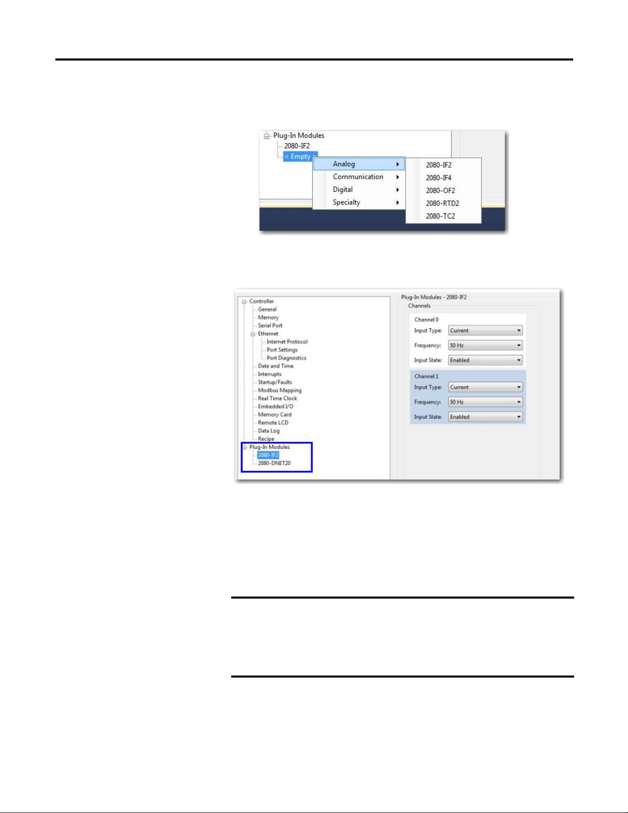
Quickstart Appendix B
IMPORTANT
• Right-click the plug-in slot in the Controller Properties tree and choose
the plug-in you would like to add.
.
The device configuration window should show the added plug-in
modules:
Browse Your 2080-DNET20 Plug-in Using RSLinx
There are two methods you can use to browse for your 2080-DNET20 plug-in
using RSLinx. The first method is browsing directly to the plug-in through the
DeviceNet network. The second method is browsing through a Micro820/
Micro830/Micro850 controller using the pass through feature. This allows you
to upgrade the firmware of the plug-in.
To use the controller pass through feature, the following firmware
revisions are required:
• Micro820/Micro830/Micro850 controller firmware revision 8.011 or
higher.
• 2080-DNET20 plug-in firmware revision 2.011 or higher.
Rockwell Automation Publication 2080-UM004C-EN-E - March 2015 81
Page 90

Appendix B Quickstart
Right-click on the plug-in and select Properties
to view the Device properties
Browse Using the DeviceNet Network
From the computer, the 2080-DNET20 plug-in can be browsed through the
DeviceNet network. This requires an additional device to connect the computer
to the DeviceNet network. For example, you can use the 1788-EN2DN or
1784-U2DN devices. For instructions on connecting the plug-in to the
DeviceNet network, see Setup and Wiring
Browsing the 2080-DNET20 plug-in through the DeviceNet network
on page89.
82 Rockwell Automation Publication 2080-UM004C-EN-E - March 2015
Page 91

Quickstart Appendix B
IMPORTANT
Browse Using the Micro800 Pass Through
To use the controller pass through feature, the following firmware
revisions are required:
• Micro820/Micro830/Micro850 controller firmware revision 8.011 or
higher.
• 2080-DNET20 plug-in firmware revision 2.011 or higher.
Browsing the 2080-DNET20 plug-in from the controller backplane through
EtherNet/IP.
Browsing the 2080-DNET20 plug-in from the controller backplane through USB.
Rockwell Automation Publication 2080-UM004C-EN-E - March 2015 83
Page 92

Appendix B Quickstart
Browsing the 2080-DNET20 plug-in from the controller backplane through Serial
DF1.
Flash Upgrade Your 2080-DNET20 Plug-in Firmware
This quick start will show you how to flash update the firmware in a
2080-DNET20 plug-in using ControlFLASH. ControlFLASH is installed or
updated when Connected Components Workbench software is installed on your
computer. It is recommended that the controller is in Program mode and the
plug-in is in Idle mode when performing the upgrade.
1. Check the firmware revision of the plug-in. To do this, check the Device Properties of the plug-in RSLinx.
84 Rockwell Automation Publication 2080-UM004C-EN-E - March 2015
Page 93

Quickstart Appendix B
2. Launch ControlFLASH and click Next.
3. In the Catalog Number dialog, select the 2080-DNET20 plug-in and click
Next.
Rockwell Automation Publication 2080-UM004C-EN-E - March 2015 85
Page 94

Appendix B Quickstart
IMPORTANT
4. The Connection Browser dialog appears, select the 2080-DNET20 plugin and click OK.
To upgrade from firmware revision 1.012 to 2.011, the DeviceNet
network should be used. From revision 2.011 onwards, you can upgrade
the firmware using the controller pass through feature.
5. Select the firmware revision to flash and click Next.
86 Rockwell Automation Publication 2080-UM004C-EN-E - March 2015
Page 95
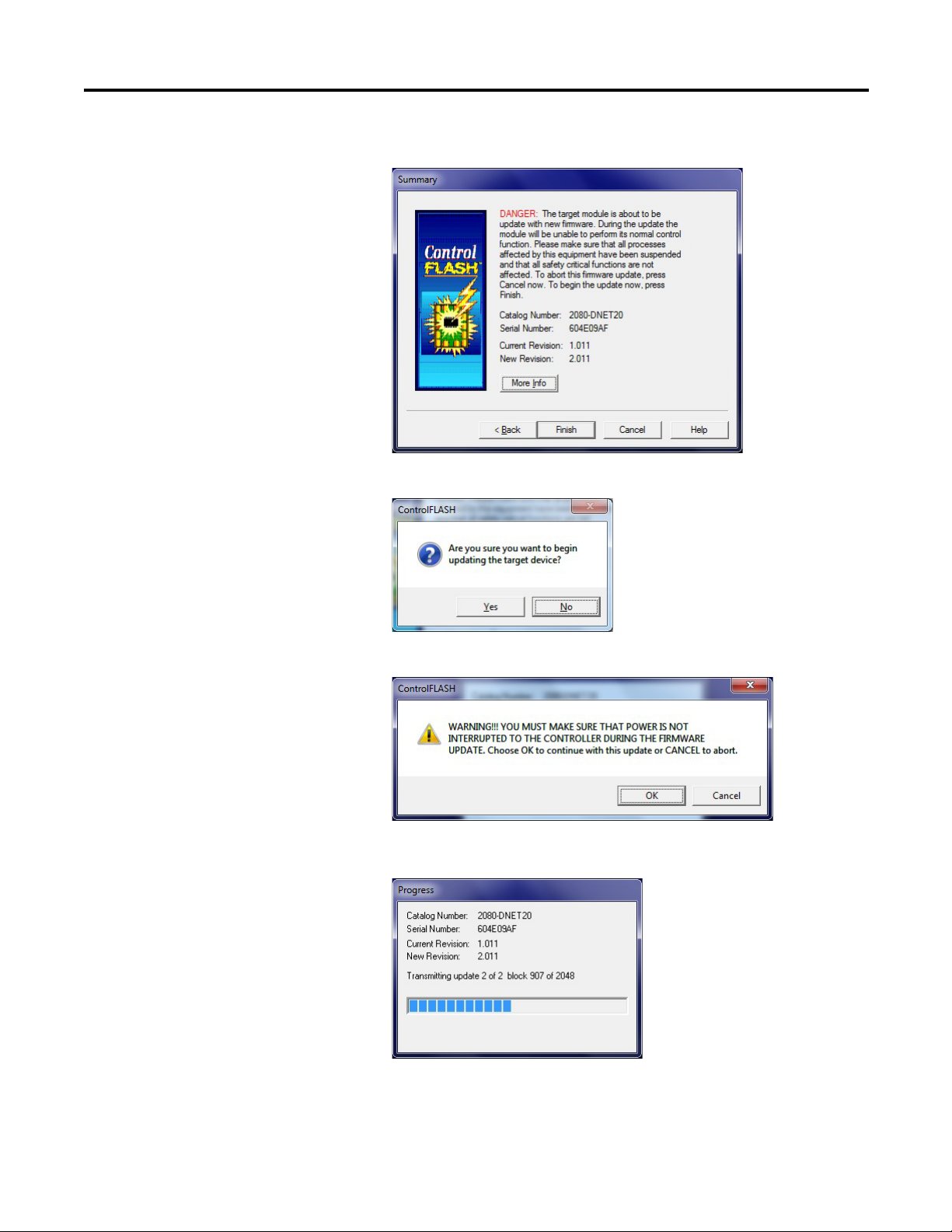
6. Verify your selection and click Finish.
7. Click Yes to continue.
Quickstart Appendix B
8. Click OK to begin the upgrade process.
A dialog showing the progress appears.
Rockwell Automation Publication 2080-UM004C-EN-E - March 2015 87
Page 96

Appendix B Quickstart
IMPORTANT
Micro800 Controller
with 2080-DNET20
Dropline
Dropline
Trunkline
Node 0
Node 1
CompactBlock LDX
Node 3
9. When the flash update is complete, the Update Status dialog appears. Check that the status is green and the update is complete. If the status is unsuccessful, power cycle the controller and restart the upgrade process.
10. After a successful firmware upgrade, power cycle the controller.
Quickstart Project for 2080-DNET20 Plug-in
Using your 2080-DNET20 plug-in module and user defined function blocks in
Connected Components Workbench, the following quickstart project shows you
how to turn on all the outputs of a CompactBlock LDX module connected in
Node 3.
Quickstart Prerequisite
For the following quickstart projects, you first need first need to
download the DNET UDFBs and sample project from the
Sample Code Library:
http://www.rockwellautomation.com/go/scmicro800
88 Rockwell Automation Publication 2080-UM004C-EN-E - March 2015
Page 97

Quickstart Appendix B
20474
Setup and Wiring
1. Insert your 2080-DNET20 module into the designated plug-in slot in your Micro800 controller.
2. Next, wire your 2080-DNET20 plug-in following the diagram shown below.
Color Chips (dots)
10-position Plug
Red Dot
White Dot
Blue Dot
Black Dot
5-position Plug
DeviceNet
Port Pinout
V+ (RED)
CANH (WHITE)
SHIELD
CANL (BLUE)
V- (BLACK)
10-position
Linear Plug
D
D
D
D
D
Red
White
Bare
Blue
Black
DeviceNet
Drop Line or
Trunk Cable
Rockwell Automation Publication 2080-UM004C-EN-E - March 2015 89
Page 98

Appendix B Quickstart
Esc
Sel
Micro800 controller
CompactBlock LDX
Component on
DeviceNet
Network
PowerFlex 523
with
25-COMM-D
COMM
power
supply
1 KwikLink Lite IP20 Flat Media
2 Trunk Line Connector
3 Drop Line Connector
4 Terminating Resistor
5 5-pin Open Style Connector
6 Power Tap with terminating resistor
46220
3. Configure the DeviceNet devices as shown below.
4. Set the node address for the CompactBlock LDX through the node
5. Set the node address for the PowerFlex drive through the 25-COMM-D to
Configuration
1. Launch Connected Components Workbench and open the sample project
2. Import the following DNET UDFBs into your project:
switches to node 1.
node 2. Set the baud rate to autobaud.
WARNING: Do not change the configuration when the Controller is in
RUN mode.
you have downloaded from the Sample Code Library.
• RA_DNET_MASTER
• RA_DNET_LDX_DISCRETE
• RA_PF_DNET_STANDARD
See User Defined Function Blocks
on page45 for information on input
and output parameters for these UDFBs.
90 Rockwell Automation Publication 2080-UM004C-EN-E - March 2015
Page 99

Quickstart Appendix B
3. Configure the RA_DNET_MASTER UDFB as shown.
4. Configure the PowerFlex UDFB as shown (that is, set the node address,
plug-in slot ID, and so on).
Rockwell Automation Publication 2080-UM004C-EN-E - March 2015 91
Page 100

Appendix B Quickstart
5. Configure the CompactBlock LDX UDFB as shown (that is, set the node address, plug-in slot ID, Module1…Module4).
Build and Download
Build and download the project into the controller.
92 Rockwell Automation Publication 2080-UM004C-EN-E - March 2015
 Loading...