

Allen-Bradley 20-750-APS, 20-750-ENETR, 20-750-DENC-1, 20-750-DNET, 20-750-PBUS Installation Instructions Manual
...Page 1

Installation Instructions
PowerFlex 750-Series AC Drives
Catalog Numbers 20F, 20G, 21G
Page 2
Important User Information
IMPORTANT
Read this document and the documents listed in the additional resources section about installation, configuration, and
operation of this equipment before you install, configure, operate, or maintain this product. Users are required to
familiarize themselves with installation and wiring instructions in addition to requirements of all applicable codes, laws,
and standards.
Activities including installation, adjustments, putting into service, use, assembly, disassembly, and maintenance are required
to be carried out by suitably trained personnel in accordance with applicable code of practice.
If this equipment is used in a manner not specified by the manufacturer, the protection provided by the equipment may be
impaired.
In no event will Rockwell Automation, Inc. be responsible or liable for indirect or consequential damages resulting from the
use or application of this equipment.
The examples and diagrams in this manual are included solely for illustrative purposes. Because of the many variables and
requirements associated with any particular installation, Rockwell Automation, Inc. cannot assume responsibility or
liability for actual use based on the examples and diagrams.
No patent liability is assumed by Rockwell Automation, Inc. with respect to use of information, circuits, equipment, or
software described in this manual.
Reproduction of the contents of this manual, in whole or in part, without written permission of Rockwell Automation,
Inc., is prohibited.
Throughout this manual, when necessary, we use notes to make you aware of safety considerations.
WARNING: Identifies information about practices or circumstances that can cause an explosion in a hazardous environment,
which may lead to personal injury or death, property damage, or economic loss.
ATTENTION: Identifies information about practices or circumstances that can lead to personal injury or death, property
damage, or economic loss. Attentions help you identify a hazard, avoid a hazard, and recognize the consequence.
Identifies information that is critical for successful application and understanding of the product.
Labels may also be on or inside the equipment to provide specific precautions.
SHOCK HAZARD: Labels may be on or inside the equipment, for example, a drive or motor, to alert people that dangerous
voltage may be present.
BURN HAZARD: Labels may be on or inside the equipment, for example, a drive or motor, to alert people that surfaces may
reach dangerous temperatures.
ARC FLASH HAZARD: Labels may be on or inside the equipment, for example, a motor control center, to alert people to
potential Arc Flash. Arc Flash will cause severe injury or death. Wear proper Personal Protective Equipment (PPE). Follow ALL
Regulatory requirements for safe work practices and for Personal Protective Equipment (PPE).
Allen-Bradley, Rockwell Software, and Rockwell Automation are trademarks of Rockwell Automation, Inc.
Trademarks not belonging to Rockwell Automation are property of their respective companies.
Page 3

Preface
Introduction
Read the General Precautions
Prepare for Installation
Lift and Mount the Drive
Instructions in Other Languages. . . . . . . . . . . . . . . . . . . . . . . . . . . . . . . . . . . . 7
Additional Resources . . . . . . . . . . . . . . . . . . . . . . . . . . . . . . . . . . . . . . . . . . . . . . 8
Commonly Used Tools . . . . . . . . . . . . . . . . . . . . . . . . . . . . . . . . . . . . . . . . . . . . 9
Chapter 1
Qualified Personnel . . . . . . . . . . . . . . . . . . . . . . . . . . . . . . . . . . . . . . . . . . . . . . 11
Personal Safety . . . . . . . . . . . . . . . . . . . . . . . . . . . . . . . . . . . . . . . . . . . . . . . . . . . 11
Product Safety . . . . . . . . . . . . . . . . . . . . . . . . . . . . . . . . . . . . . . . . . . . . . . . . . . . 12
Class 1 LED Product . . . . . . . . . . . . . . . . . . . . . . . . . . . . . . . . . . . . . . . . . . . . . 12
Chapter 2
Wall Mount Frames 1…7 Drive Rating Cross-References . . . . . . . . . . . . 15
Floor Mount Frames 8…10 Drive Rating Cross-References . . . . . . . . . . 17
CE Conformity . . . . . . . . . . . . . . . . . . . . . . . . . . . . . . . . . . . . . . . . . . . . . . . . . . 18
Access Panels, Covers, and Doors . . . . . . . . . . . . . . . . . . . . . . . . . . . . . . . . . . 24
Minimum Clearances. . . . . . . . . . . . . . . . . . . . . . . . . . . . . . . . . . . . . . . . . . . . . 32
Mounting Considerations. . . . . . . . . . . . . . . . . . . . . . . . . . . . . . . . . . . . . . . . . 33
Environmental Specifications . . . . . . . . . . . . . . . . . . . . . . . . . . . . . . . . . . . . . 33
Chapter 3
Drive Weights . . . . . . . . . . . . . . . . . . . . . . . . . . . . . . . . . . . . . . . . . . . . . . . . . . . 35
Recommended Mounting Hardware. . . . . . . . . . . . . . . . . . . . . . . . . . . . . . . 36
Attach Lifting Hardware. . . . . . . . . . . . . . . . . . . . . . . . . . . . . . . . . . . . . . . . . . 37
Release Floor Mount Drive Cabinet From Shipping Skid . . . . . . . . . . . . 41
Remove Drive Cabinet Lifting Angle . . . . . . . . . . . . . . . . . . . . . . . . . . . . . . 42
Install IP20, NEMA/UL Type 1 Debris Screen or
Optional Exhaust Hood . . . . . . . . . . . . . . . . . . . . . . . . . . . . . . . . . . . . . . . . . . 43
Install IP54, NEMA 12 Cabinet Blower Assembly and Exhaust Hood 43
Install Floor Mount Drive with Cabinet Options Bay and Wiring Bay 44
Approximate Dimensions - Wall Mount Frames 1…7 and
Floor Mount Frames 8…10. . . . . . . . . . . . . . . . . . . . . . . . . . . . . . . . . . . . . . . . 52
Approximate Dimensions - Floor Mount Drives
with Cabinet Options . . . . . . . . . . . . . . . . . . . . . . . . . . . . . . . . . . . . . . . . . . . . 82
Release Drive Assembly From Cabinet . . . . . . . . . . . . . . . . . . . . . . . . . . . . 118
Fiber-Optic Cables . . . . . . . . . . . . . . . . . . . . . . . . . . . . . . . . . . . . . . . . . . . . . . 121
Disconnect Drive Control Pod Wiring Connections . . . . . . . . . . . . . . . 121
Disconnect Wire Connections - No Drive Control Pod . . . . . . . . . . . . 123
Disconnect Control and Power Wire Harnesses . . . . . . . . . . . . . . . . . . . 125
Disconnect DC Bus Fuse Wire Harness . . . . . . . . . . . . . . . . . . . . . . . . . . . 125
Release Cabinet Options Assembly From Cabinet . . . . . . . . . . . . . . . . . 127
Prepare the Roll-Out Cart . . . . . . . . . . . . . . . . . . . . . . . . . . . . . . . . . . . . . . . 129
Remove Drive Assembly or Cabinet Options Assembly. . . . . . . . . . . . . 138
Remove DC Back Bus Guard - Common DC Input Drives . . . . . . . . . 143
Reinstall Drive Assembly or Cabinet Options Assembly . . . . . . . . . . . . 144
Rockwell Automation Publication 750-IN001O-EN-P - October 2014 3
Page 4

Chapter 4
Power Wiring
Grounding Requirements . . . . . . . . . . . . . . . . . . . . . . . . . . . . . . . . . . . . . . . . 145
Power Cable Types Acceptable for 200…600 Volt Installations. . . . . . 147
Motor Considerations . . . . . . . . . . . . . . . . . . . . . . . . . . . . . . . . . . . . . . . . . . . 147
Terminal Block Specifications . . . . . . . . . . . . . . . . . . . . . . . . . . . . . . . . . . . . 147
Three-Phase Terminal Locations . . . . . . . . . . . . . . . . . . . . . . . . . . . . . . . . . 149
Wall Mount Frames 1…7 AC Input Power Terminals . . . . . . . . . . . . . . 151
Wall Mount Frames 5…7 Common DC Input Terminal Locations. . 153
Wall Mount Frames 5…7 Common DC Input Power Terminals . . . . 155
Floor Mount Frames 8…10 Bus Bar Locations . . . . . . . . . . . . . . . . . . . . . 156
Floor Mount Cabinet Options Bay . . . . . . . . . . . . . . . . . . . . . . . . . . . . . . . 159
Floor Mount Frames 8…10 Power Wiring Options . . . . . . . . . . . . . . . . 161
Floor Mount Frames 8…10 Power Terminal L-Brackets . . . . . . . . . . . . 162
Recommended Motor Cable Spacing -
Floor Mount Frames 8 and Larger . . . . . . . . . . . . . . . . . . . . . . . . . . . . . . . . 164
Fuse and Circuit Breaker Ratings . . . . . . . . . . . . . . . . . . . . . . . . . . . . . . . . . 167
Motor Overload Protection . . . . . . . . . . . . . . . . . . . . . . . . . . . . . . . . . . . . . . 184
Short Circuit Current Rating . . . . . . . . . . . . . . . . . . . . . . . . . . . . . . . . . . . . 184
Short Circuit Current Ratings -
Floor Mount Drives with Cabinet Options. . . . . . . . . . . . . . . . . . . . . . . . 185
Input Contactor Precautions. . . . . . . . . . . . . . . . . . . . . . . . . . . . . . . . . . . . . 191
Output Contactor Precaution. . . . . . . . . . . . . . . . . . . . . . . . . . . . . . . . . . . . 191
Bypass Contactor Precaution. . . . . . . . . . . . . . . . . . . . . . . . . . . . . . . . . . . . . 191
Applying and Removing Power. . . . . . . . . . . . . . . . . . . . . . . . . . . . . . . . . . . 191
Drives with Cabinet Options. . . . . . . . . . . . . . . . . . . . . . . . . . . . . . . . . . . . . 192
Input Power Circuit Breakers and Disconnect Switches . . . . . . . . . . . . 194
Cabinet Options Bay Accessories . . . . . . . . . . . . . . . . . . . . . . . . . . . . . . . . . 198
Drive Power Jumper Configuration. . . . . . . . . . . . . . . . . . . . . . . . . . . . . . . 209
Chapter 5
I/O Wiring
4 Rockwell Automation Publication 750-IN001O-EN-P - October 2014
I/O Terminal Blocks . . . . . . . . . . . . . . . . . . . . . . . . . . . . . . . . . . . . . . . . . . . . 220
Access Drive Control Pod. . . . . . . . . . . . . . . . . . . . . . . . . . . . . . . . . . . . . . . . 222
PowerFlex 753 Main Control Board . . . . . . . . . . . . . . . . . . . . . . . . . . . . . . 226
PowerFlex 755 Main Control Board . . . . . . . . . . . . . . . . . . . . . . . . . . . . . . 228
Hardware Enable Circuitry . . . . . . . . . . . . . . . . . . . . . . . . . . . . . . . . . . . . . . 230
Safety Enable Circuitry . . . . . . . . . . . . . . . . . . . . . . . . . . . . . . . . . . . . . . . . . . 232
PowerFlex 755 Fiber Optic Interface Board . . . . . . . . . . . . . . . . . . . . . . . 233
AC Input Drive Control and Power Terminal Block . . . . . . . . . . . . . . . 234
Common DC Input Drive Control and Power Terminal Blocks . . . . 235
Control Transformer Connections - Common DC Input Drives. . . . 238
Uninterruptible Power Supply Connections -
Common DC Input Drives . . . . . . . . . . . . . . . . . . . . . . . . . . . . . . . . . . . . . . 239
120/240V AC Power Supply Connections -
Common DC Input Drives . . . . . . . . . . . . . . . . . . . . . . . . . . . . . . . . . . . . . . 240
753 Main Control Board I/O Wiring Examples . . . . . . . . . . . . . . . . . . . 241
Page 5

Drive Device Ports . . . . . . . . . . . . . . . . . . . . . . . . . . . . . . . . . . . . . . . . . . . . . . 244
Option Module Installation. . . . . . . . . . . . . . . . . . . . . . . . . . . . . . . . . . . . . . 245
11-Series I/O Module . . . . . . . . . . . . . . . . . . . . . . . . . . . . . . . . . . . . . . . . . . . 246
11-Series I/O Wiring Examples. . . . . . . . . . . . . . . . . . . . . . . . . . . . . . . . . . . 248
22-Series I/O Module . . . . . . . . . . . . . . . . . . . . . . . . . . . . . . . . . . . . . . . . . . . 255
22-Series I/O Wiring Examples. . . . . . . . . . . . . . . . . . . . . . . . . . . . . . . . . . . 257
Safe Torque Off Option Module . . . . . . . . . . . . . . . . . . . . . . . . . . . . . . . . . 262
Safe Speed Monitor Option Module . . . . . . . . . . . . . . . . . . . . . . . . . . . . . . 264
Auxiliary Power Supply Option Module . . . . . . . . . . . . . . . . . . . . . . . . . . 266
DeviceNet Option Module . . . . . . . . . . . . . . . . . . . . . . . . . . . . . . . . . . . . . . 267
ControlNet Option Module . . . . . . . . . . . . . . . . . . . . . . . . . . . . . . . . . . . . . 268
Dual-Port EtherNet/IP Option Module . . . . . . . . . . . . . . . . . . . . . . . . . . 269
Profibus Option Module. . . . . . . . . . . . . . . . . . . . . . . . . . . . . . . . . . . . . . . . . 270
BACnet/IP Option Module . . . . . . . . . . . . . . . . . . . . . . . . . . . . . . . . . . . . . 271
20-COMM Carrier . . . . . . . . . . . . . . . . . . . . . . . . . . . . . . . . . . . . . . . . . . . . . 272
Single Incremental Encoder Option Module. . . . . . . . . . . . . . . . . . . . . . . 273
Dual Incremental Encoder Option Module. . . . . . . . . . . . . . . . . . . . . . . . 275
Universal Feedback Option Module - 755 Drives Only . . . . . . . . . . . . . 279
Motor Power Cables. . . . . . . . . . . . . . . . . . . . . . . . . . . . . . . . . . . . . . . . . . . . . 282
Feedback Device Resolution. . . . . . . . . . . . . . . . . . . . . . . . . . . . . . . . . . . . . . 282
Motor Feedback Wiring Examples. . . . . . . . . . . . . . . . . . . . . . . . . . . . . . . . 282
Control Pod Cable Routing . . . . . . . . . . . . . . . . . . . . . . . . . . . . . . . . . . . . . . 292
Control Wiring - Early Frame 8 Drives with Cabinet Options . . . . . . 293
Control Wiring - Current Frame 8 Drives with Cabinet Options . . . 295
Control Wiring - Frame 9 and 10 Drives with Cabinet Options. . . . . 296
Enclosure Options - Floor Mount Frames 8…10 . . . . . . . . . . . . . . . . . . . 298
Integrated Motion Drives
Configuring Option Modules for Integrated Motion . . . . . . . . . . . . . . . 299
Rockwell Automation Publication 750-IN001O-EN-P - October 2014 5
Page 6

Notes:
6 Rockwell Automation Publication 750-IN001O-EN-P - October 2014
Page 7

Preface
Introduction
This document explains the BASIC STEPS for mechanical installation and for
connecting incoming power, the motor, and basic I/O to the PowerFlex 750Series Adjustable Frequency AC drive.
The information that is provided is intended for qualified installers only.
The Additional Resources section is a directory of Rockwell Automation
publications that provide detailed drive information from wiring and grounding
recommendations to troubleshooting and repair.
Instructions in Other Languages
English This instruction sheet is available in multiple languages at
German Diese Anleitung steht in mehreren Sprachen unter
French Ces instructions sont disponibles dans différentes langues à l’adresse suivante:
Italian La presente scheda d’istruzione è disponibile in varie lingue sul sito
Spanish Puede encontrar esta hoja de instrucciones en varios idiomas en
Portuguese Esta folha de instruções está disponível em várias línguas em
Chinese
(Simplified)
Japanese 本説明書シートの多言語版は Web サイト
Korean
Russian
Chinese
(Complex)
Czech Tato stránka s pokyny je k dispozici ve více jazykových verzích na adrese
http://rockwellautomation.com/literature. Select publication language and type “750-IN001“ in the
search field.
http://rockwellautomation.com/literature zur Verfügung. Wählen Sie Ihre Sprache aus, und geben Sie
„750-IN001“ in das Suchfeld ein.
http://rockwellautomation.com/literature
champ de recherche.
http://rockwellautomation.com/literature
nel campo di ricerca.
http://rockwellautomation.com/literature. Selecione el idioma de publicación y escriba “750-IN001“
en el campo de búsqueda.
http://rockwellautomation.com/literature
IN001“ no espaço de busca.
从以下网页可以获得本说明书的多种语言的版本 :
http://rockwellautomation.com/literature
请选择出版物的语言 , 并在搜索栏输入 “750-IN001” 印。
http://rockwellautomation.com/literature
にて入手できます。出版言語を選択し、検索フィールドに 「750-
IN001
」とタイプしてください。
㢨 ⮹⥭ ⺴ http://rockwellautomation.com/literature㜄㉐ 㜠⤠ 㛬㛨⦐ ㇠㟝䚔 ㍌㢼㏩⏼␘.
㻐䑄 㛬㛨㝴 㡔䝉㡸 ㉔䈑䚌㐡㐐㝘 "750 - IN001"ᶴㇽ 䙸☐㜄㢼␘.
. Sélectionner la langue puis taper « 750-IN001 » dans le
. Selezionare la lingua desiderata e digitare “750-IN001“
. Seleccione a língua de publicação e entre com “750-
。
Данное руководство на других языках можно найти по адресу
http://rockwellautomation.com/literature. Выберите язык и введите в окно поиска «750-IN001».
以下網頁提供本說明書的多國語言版本:
http://rockwellautomation.com/literature
“750-IN001” 即可。
http://rockwellautomation.com/literature. Zvolte jazyk publikace a do vstupního pole pro
. 請選擇出版語言,並於搜尋欄鍵入
vyhledávání zadejte „750-IN001“.
Polis h Niniejsza instrukcja dostępna jest w wielu językach na stronie
http://rockwellautomation.com/literature. Wybrać język publikacji, w polu wyszukiwania wpisać
“750-IN001”.
Rockwell Automation Publication 750-IN001O-EN-P - October 2014 7
Page 8
Preface
Additional Resources
The following table lists publications that provide general drive-related
information.
Resource Description
PowerFlex 750-Series AC Drives Programming Manual,
publication 750-PM001
PowerFlex 750-Series AC Drives Technical Data,
publication 750-TD001
PowerFlex 20-HIM-A6 / -C6S HIM (Human Interface
Module) User Manual, publication 20HIM-UM001
PowerFlex 750-Series AC Drives Hardware Service Manual
- Frame 8 and Larger, publication 750-TG001
PowerFlex 755 Drive Embedded EtherNet/IP Adapter User
Manual, publication 750COM-UM001
PowerFlex 750-Series Drive DeviceNet Option Module User
Manual, publication 750COM-UM002
PowerFlex 7-Class Network Communication Adapter User
Manuals, publications 750COM-UMxxx
PowerFlex 750-Series Safe Torque Off User Manual,
publication 750-UM002
Safe Speed Monitor Option Module for PowerFlex
750-Series AC Drives Safety Reference Manual, publication
750-RM001
Wiring and Grounding Guidelines for Pulse Width
Modulated (PWM) AC Drives, publication DRIVES-IN001
PowerFlex AC Drives in Common Bus Configurations,
publication DRIVES-AT002
Safety Guidelines for the Application, Installation, and
Maintenance of Solid-State Control, publication SGI-1.1
Guarding Against Electrostatic Damage, publication 8000-
4.5.2
Product Certifications website, http://ab.com
Provides detailed information on:
• I/O, control, and feedback options
• Parameters and programming
• Faults, alarms, and troubleshooting
Provides detailed information on:
• Drive specifications
• Option specifications
• Fuse and circuit breaker ratings
Provides detailed information on HIM components,
operation, features.
Provides detailed information on:
• Preventive maintenance
• Component testing
• Hardware replacement procedures
These publications provide detailed information on to
configure, use, and troubleshoot PowerFlex 750-Series
communication option modules and adapters.
These publications provide detailed information on to
install, configure, and operate the 750-Series safety
option modules.
Provides basic information to properly wire and ground
PWM AC drives.
Provides basic information to properly wire and ground
PWM AC drives with a common bus.
Provides general guidelines for the application,
installation, and maintenance of solid-state control.
Provides practices for guarding against Electrostatic
damage (ESD)
Provides declarations of conformity, certific ates, and other
certification details.
8 Rockwell Automation Publication 750-IN001O-EN-P - October 2014
Page 9

Preface
IMPORTANT
Commonly Used Tools
Installation and Service Tools
Care must be taken to be sure that tools and/or hardware components do not
fall into open drive assemblies. Do not energize the drive unless all loose tools
and/or hardware components have been removed from the drive assemblies
and enclosure.
This list covers the tools that are needed for drive installation.
Tool Description Details
ESD-protected place of work Work surface, Floor cover, seat, and ground connections
ESD-protective clothing Wrist wrap, shoes, overall clothing (coat)
Multimeter Digital multimeter, capable of AC and DC voltage, continuity, resistance,
Allen socket wrench 4 mm, 5 mm
Allen-socket wrench extension 254 mm (10 in.)
Flat-nose screw driver 5 mm (0.19 in.), 6.4 mm (0.25 in.), 9.5 mm (0.375 in.), #1, #2
Hexalobular screw driver/bit #15, #20, #25, #40, #45
Hexagonal socket wrench 7 mm, 8 mm, 10 mm, 12 mm, 13 mm, 17 mm, 18 mm
Combination wrench 10 mm, 17 mm
Phillips® screw driver/bit
(1)
Pozid riv®
Torque wrench 1...12 N•m (8.8…106 lb•in)
Torque wrench 6...50 N•m (53…443 lb•in)
Roll-out cart 20-750-CART1-F8
(1)
capacitance measurements, and fo rward diode bias tests. Fluke model 87 III or
equivalent.
#2, 492-C
#2, M3 x 7
Note: The roll-out car t is required to remove the Frame 8 and larger drive
assembly from the enclosure.
(1) Phillips and Pozidriv are registered trademarks of the Phillips Screw Company.
Rockwell Automation Publication 750-IN001O-EN-P - October 2014 9
Page 10

Preface
Notes:
10 Rockwell Automation Publication 750-IN001O-EN-P - October 2014
Page 11
Qualified Personnel
Personal Safety
Read the General Precautions
ATTENTION: Only qualified personnel familiar with adjustable frequency AC
drives and associated machinery should plan or implement the installation,
start-up and subsequent maintenance of the system. Failure to comply may
result in personal injury and/or equipment damage.
ATTENTION: To avoid an electric shock hazard, verify that the voltage on the
bus capacitors has discharged completely before servicing.
Frames 1…7: Measure the DC bus voltage at the power terminal block by
measuring between the +DC and -DC terminals (see Figure 88
location) or between the +DC and -DC test point sockets if equipped. Also measure
between the +DC terminal or test point and the chassis, and between the -DC
terminal or testpoint and the chassis. The voltage must be zero for all three
measurements.
Frames 8…10: Measure the DC bus voltage at the DC+ and DC- TESTPOINT
sockets on the front of the power module (see Figure 92
Chapter 1
and Figure 89 for
for location).
ATTENTION: Hazard of personal injury or equipment damage exists when using
bipolar input sources. Noise and drift in sensitive input circuits can cause
unpredictable changes in motor speed and direction. Use speed command
parameters to help reduce input source sensitivity.
ATTENTION: Risk of injury or equipment damage exists. DPI or SCANport host
products must not be directly connected together via 1202 cables.
Unpredictable behavior can result if two or more devices are connected in this
manner.
ATTENTION: The drive start/stop/enable control circuitry includes solid state
components. If hazards due to accidental contact with moving machinery or
unintentional flow of liquid, gas or solids exists, an additional hardwired stop
circuit may be required to remove the AC line to the drive. An auxiliary braking
method may be required.
ATTENTION: Hazard of personal injury or equipment damage due to
unexpected machine operation exists if the drive is configured to automatically
issue a Start or Run command. Do not use these functions without considering
applicable local, national and international codes, standards, regulations or
industry guidelines.
Rockwell Automation Publication 750-IN001O-EN-P - October 2014 11
Page 12
Chapter 1 Read the General Precautions
Product Safety
ATTENTION: An incorrectly applied or installed drive can result in component
damage or a reduction in product life. Wiring or application errors such as under
sizing the motor, incorrect or inadequate AC supply, a corrosive environment, or
excessive surrounding air temperatures may result in malfunction of the
system.
ATTENTION: This drive contains ESD (Electrostatic Discharge) sensitive parts
and assemblies. Static control precautions are required when installing, testing,
servicing or repairing this assembly. Component damage may result if ESD
control procedures are not followed. If you are not familiar with static control
procedures, reference Guarding Against Electrostatic Damage, publication
8000-4.5.2 or any other applicable ESD protection handbook.
ATTENTION: Configuring an analog input for 0…20 mA operation and driving
it from a voltage source could cause component damage. Verify proper
configuration prior to applying input signals.
Class 1 LED Product
ATTENTION: Hazard of permanent eye damage exists when using optical
transmission equipment. This product emits intense light and invisible
radiation. Do not look into module ports or fiber optic cable connectors.
12 Rockwell Automation Publication 750-IN001O-EN-P - October 2014
Page 13
Chapter 2
a
b
c
d
e
f1
f2
Drive
Code Type Frames
20F PowerFlex 753 1…7
20G PowerFlex 755 1…10
21G PowerFlex 755 Drive with Options 8…10
Future Use
Input
Ty p e
Code Descrip tion Frames
1
AC Input with Precharge,
includes DC Terminals
1…5
8…10
4 DC Input with
Precharge
5…10
A AC Input with Precharge, no DC
Ter mi na l s
6…8
(1)
(1) The DC Bus B ar kit
(20-750-DCBB1-Fx)
is available for Frames
6…7
AC input drives th at require DC bus
terminals.
Enclosure
Code Description Frames
R IP20, NEMA/UL Type Open, Frame 1 1
F
(1)
(1) For Frames 6…7 a user installed Flange kit (20-750-FLNG4-Fx) is
available to convert a Code N drive that provides a NEMA/UL Type
4X/12 back.
Flange (NEMA/UL Type 4X/12 back) 2…5
G IP54, NEMA/UL Type 12 2…7
N
(2)
(2) Frames 2…5 are IP20, Frames 6…7 are IP00.
IP20/IP00, NEMA/UL Type Open 2…7
B
(3)
(3) Available as a drive with options (21G).
IP20, NEMA/UL Type 1,
600 mm (23.6 in.) Deep,
Standard Cabinet Color (RAL 7032)
8…10
J
(3)
IP54, UL Type 12,
800 mm (31.5 in.) Deep,
Standard Cabinet Color (RAL 7032)
8…10
K
(3)
IP54, NEMA 12,
2500 MCC Style Cabinet and Options w/MCC
Power Bus, 800 mm (31.5 in.) Deep,
Standard Cabinet Color (RAL 7032)
8…10
L
(3)
IP20, NEMA/UL Type 1,
800 mm (31.5 in.) Deep,
Standard Cabinet Color (RAL 7032)
8…10
P
(3)
IP20, NEMA/UL Type 1,
2500 MCC Style Cabinet and Options w/MCC
Power Bus, 800 mm (31.5 in.) Deep,
Standard Cabinet Color (RAL 7032)
8…10
W
(3)
IP20, NEMA/UL Type 1,
2500 MCC Style Cabinet and Options w/MCC
Power Bus, 800 mm (31.5 in.) Deep,
CenterLine 2100 Gray (ASA49)
8…10
Y
(3)
IP54, NEMA 12,
2500 MCC Style Cabinet and Options w/MCC
Power Bus, 800 mm (31.5 in.) Deep,
CenterLine 2100 Gray (ASA49)
8…10
T IP00, UL Open Type without Control POD 8…10
Voltage Rating
Code Voltage
C 400V AC/540V
DC
D 480V AC/650V
DC
E 600V AC/810V
DC
F 690V AC/932V DC (not UL
listed)
ND Rating
400V, 50 Hz Input
Code Amps kW
Frame
Enclosure Code
B, J,
L, T
FGN
K, P,
W, Y
R
2P1 2.1 0.75
–
222
–
1
3P5 3.5 1.5
5P0 5.0 2.2
8P7 8.7 4
011 11.5 5.5
015 15.4 7.5
022 22 11
–
030 30 15
333037 37 18.5
043 43 22
060 60 30
4
4
4
072 72 37
5
085 85 45
55
104 104 55
6
140 140 75
(1)
(1) For Frames 6…7 a user installed Flange kit (20-750-FLNG4-Fx) is
available to convert a Code N drive that provides a NEMA/UL Type
4X/12 back.
6
170 170 90
205 205 110
260 260 132
7
302 302 160
7367 367 200
456 456 250
460 460 250
8
–––
8
(2)
(2) Available as a drive with options (21G ).
540 540 315
567 567 315
650 650 355
750 750 400
770 770 400
910 910 500
99
(2)
1K0 1040 560
1K1 1090 630
1K2 1175 710
1K4 1465 800
1K5 1480 850
1K6 1590 900
10 10
(2)
2K1 2150 1250
ND Rating
480V, 60 Hz Input
Code Amps Hp
Frame
Enclosure Code
B, J,
L, T
FGN
K, P,
W, Y
R
2P1 2.1 1
–
222
–
1
3P4 3.4 2
5P0 5.0 3
8P0 8.0 5
011 11 7.5
014 14 10
022 22 15
–
027 27 20
333034 34 25
040 40 30
052 52 40
4
4
4
065 65 50
5
077 77 60
55
096 96 75
6
125 125 100
(1)
(1) For Frames 6…7 a user installed Flange kit (20-750-FLNG4-Fx) is
available to convert a Code N drive that provides a NEMA/UL Type
4X/12 back.
6
156 156 125
186 186 150
248 248 200
7
302 302 250
7361 361 300
415 415 350
430 430 350
8
–––
8
(2)
(2) Available as a drive with options (21G).
485 485 400
545 545 450
617 617 500
710 710 600
740 740 650
800 800 700
99
(2)
960 960 800
1K0 1045 900
1K2 1135 1000
1K3 1365 1100
1K4 1420 1250
1K5 1525 1350
10 10
(2)
2K0 2070 1750
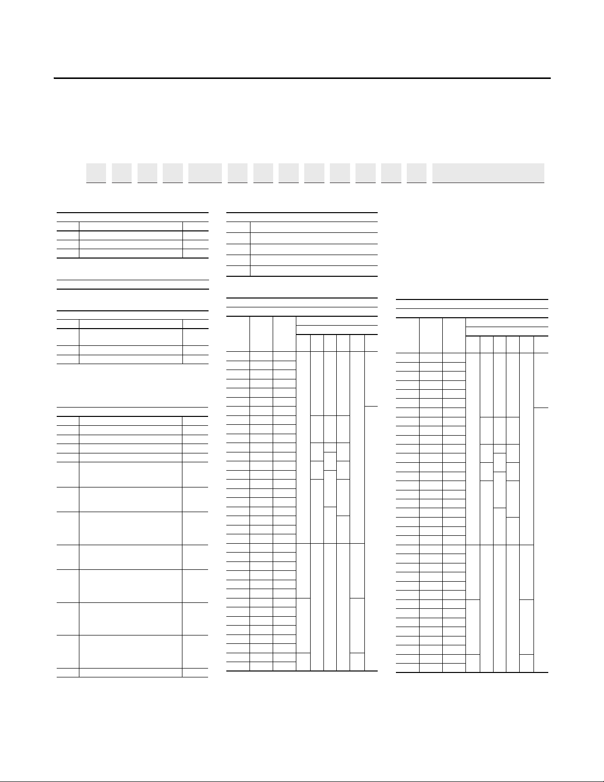
Prepare for Installation
Catalog Number Explanation
1…3 4 5 6 7 8…10 11 12 13 14 15 16 17 18
20G 1 A N D 248 A A 0 N N N N N -LD-P3-P11…
abcde ghif1…f4 Cabinet Options (21G)
Rockwell Automation Publication 750-IN001O-EN-P - October 2014 13
Page 14
Chapter 2 Prepare for Installation
f3 f4
g
h
i
PowerFlex 755 w/Options (21G)
Required Selections
PowerFlex 755 w/Options (21G)
Additional Selections
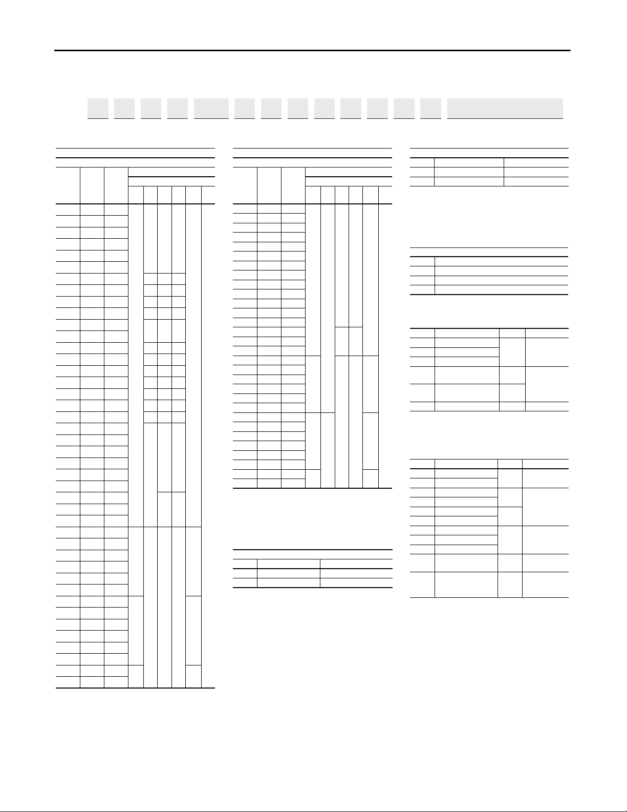
ND Rating
600V, 60 Hz Input
Code Amps Hp
Frame
Enclosure Code
B, J,
L, T
FGN
K, P,
W, Y
R
1P7 1.7 1
–
333
–
–
2P7 2.7 2
3P9 3.9 3
6P1 6.1 5
9P0 9 7.5
011 11 1 0
012
(1)
(1) Required for uncontrolled common DC bus appl ications. Optional
for all AC applications.
12 10
–66
017 17 1 5
333
018
(1)
18 15
–66
022 22 2 0
333
023
(1)
23 20
–66
024
(1)
24 20
027 27 2 5
444
028
(1)
28 25
–66
032 32 3 0
444
033
(1)
33 30
–66
041 41 4 0
555
042
(1)
42 40
–66
052 52 5 0
5–5
053
(1)
53 50
(2)
(2) For Frames 6…7 a user installed Flange kit (20-750-FLNG4-Fx) is
available to convert a Code N drive that provides a NEMA/UL Type
4X/12 back.
66
063 63 6 0
077 77 7 5
09999100
125 125 125
144 144 150
192 192 200
77
242 242 250
289 289 300
295 295 300
8
–––
8
(3)
(3) Available as a drive with options (21G).
355 355 350
395 395 400
435 435 450
460 460 500
510 510 500
595 595 600
99
(3)
630 630 700
760 760 800
825 825 900
900 900 950
980 980 1000
1K1 1110 1100
10 10
(3)
1K4 1430 1400
ND Rating
690V, 50 Hz Input (not UL listed)
Code Amps kW
Frame
Enclosure Code
B, J,
L, T
FGN
K, P,
W, Y
R
012 12 7.5
–
(1)
(1) For Frames 6…7 a user installed Flange kit (20-750-FLNG4-Fx) is
available to convert a Code N drive that provides a NEMA/UL Type
4X/12 back.
66
–
–
015 15 11
020 20 15
023 23 18.5
030 30 22
034 34 30
046 46 37
050 50 45
061 61 55
082 82 75
098 98 90
119 119 110
142 142 132
171 171 160
77212 212 200
263 263 250
265 265 250
8
––
8
(2)
(2) Available as a drive with options (21G ).
330 330 315
370 370 355
415 415 400
460 460 450
500 500 500
590 590 560
9
–
9
(2)
650 650 630
710 710 710
765 765 750
795 795 800
960 960 900
1K0 1040 1000
10 10
(2)
1K4 1400 1400
Filtering and CM Cap Configuration
(1)
(1) 480V drives must select code “A.” Jumpers are included for field
reconfiguration as desired.
Code Filtering Default CM Cap
Conne cti on
AYes Jumper
Removed
J Yes Jumper
Installed
Dynamic Braking
(1)
(1) Not available on Frames 8…10, specify Code “N.”
Code Internal Resistor
(2)
(2) Frames 1…2 only. Internal Resistor kits (20-750-DB1-Dx) sold
separately.
Internal Transistor
(3)
(3) Standard on Frames 1…5, optional on 6…7.
ANo Yes
NNo No
Door Mounted HIM (Frames
8…10)
Code Opera tor
Interface
0 No Door Mounted
HIM
2 Enhanced LCD, Full Nume ric,
IP20
4 Enhanced LCD, Full Numeric, IP66 NEMA Type
4X/12
Code Option Frames Type
LD Light
Duty
8…10
System Overload
Duty Cycle
(1)
(1) Only one option of this type ma y be selected.
ND Normal
Duty
HD Heavy
Duty
P3
Input Thermal
Magnetic
Circuit
Breaker
8…10
Power
Disconnect
(1)
P5
Input Non-Fused
Molded
Case Disconnect
Switch
8 Only
P14 Wiring Only
Bay
8…10 Wiring Only Bay
Code Option Frames Type
P11 Input
Contactor
8 Only Contactors
(1)(2)
(1) Only one option of this type ma y be selected.
(2) Contactor options are not available for systems with MCC power
bus.
P12 Output
Contacto r
L1 3% Input
Reactor
8…9
Reactors
(1)
L2 3% Output
Reactor
L3 5% Input
Reactor
8 Only
L4 5% Output
Reactor
P20 1200 Amp
Bus
8…10
MCC Power
Bus
Capacity
(1)
P22 2000 Amp
Bus
P24 3000 Amp
Bus
P30
UPS Control Bus, DC Input
w/Precharge only
8…10 UPS Control
Bus
X1
Auxiliary
Tra nsf o rme r
(500VA available),
IP20
Cabinet
Only
8 Only
(3)
(3) Standard on all other cabinet configurations.
Auxiliary
Power
Catalog Number Explanation (continued)
1…3 4 5 6 7 8…10 11 12 13 14 15 16 17 18
20G 1 A N D 248 A A 0 N N N N N -LD-P3-P11…
abcde ghif1…f4 Cabinet Options (21G)
14 Rockwell Automation Publication 750-IN001O-EN-P - October 2014
Page 15
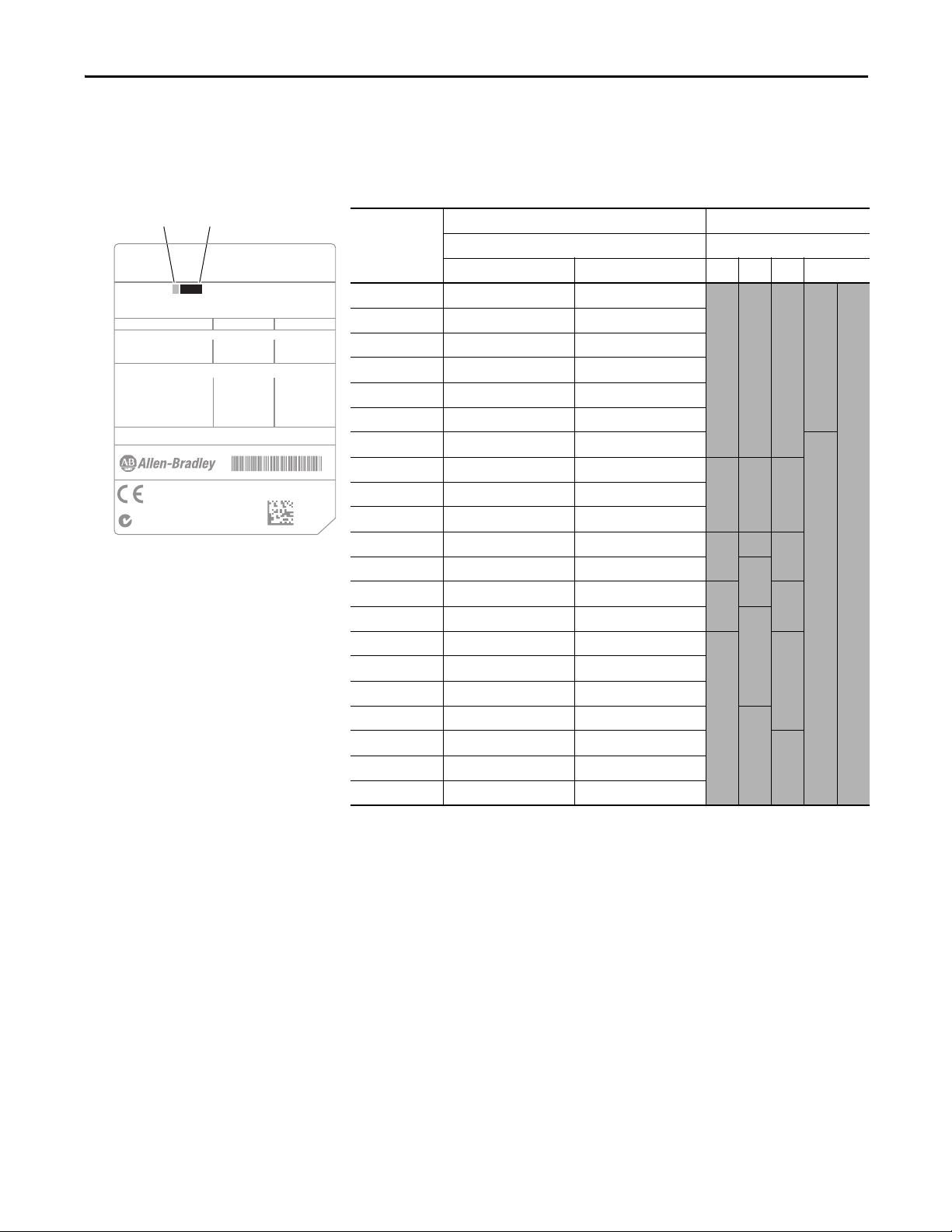
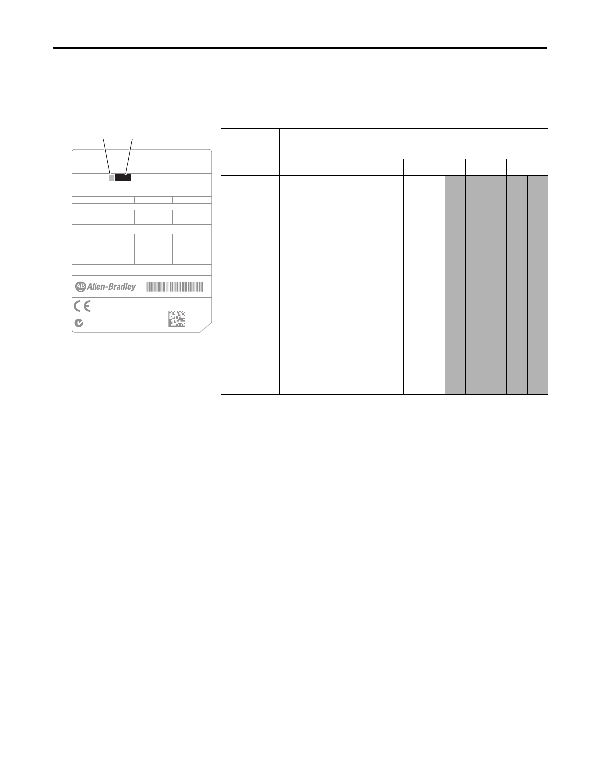
Wall Mount Frames 1…7
Cat No. 20G11 N D 011 AA0NNNNN
UL Type 1 - only with Debris Hood and Conduit Plate
UL Open Type/IP20 - without Debris Hood and Conduit Plate
Specifications and Custom Catalog Number
representing options installed at factory.
See Nameplate 2 (Located behind HIM)
for equivalent base catalog number and separate options
Nameplate 1:
Mfd. in 2009 on Jan. 19
Series: A
Input: 3 Phase, 47-63Hz
AC Voltage Range
Amps ND (HD)
Power ND (HD)
Output: 3 Phase, 0-400 Hz
AC Voltage Range
Base Frequency (default)
Continuous Amps ND (HD)
60Sec Ovld Amps ND (HD)
3 Sec Ovld Amps ND (HD)
0-400
50 Hz
342-440 432-528
0-460
60 Hz
xxx
xxx
xxx
xxx
xxx
xxx
xxx
xxx
xxx
xxx
xxx
xxx
xxx xxx xxx xxx
5.5 HP (4 HP) 7.5 HP (5 HP)
N223
Serial Number: xxxxxxxx
Original Firmware: x.xxx
Made in the U.S.A. Fac1C
400V Class 480V Class
➊ ➋
Drive Nameplate 1, Wall Mount Frames 1…7
Drive Rating Cross-references
Prepare for Installation Chapter 2
➋➊
Drive Code
Input Voltage and ND Amp Rating Enclosure Code
400V AC 480V AC F G N R
20F or 20G C2P1 D2P1
2 2 2 1
20F or 20G C3P5 D3P4
20F or 20G C5P0 D5P0
20F or 20G C8P7 D8P0
20F or 20G C011 D011
20F or 20G C015 D014
20F or 20G C022 D022
20F or 20G C030 D027 3 3 3
20F or 20G C037 D034
20F or 20G C043 D040
20F or 20G C060 D052
20F or 20G C072 D065
4 4 4
5
20F or 20G C085 D077 5 5
20F or 20G C104 D096 6
20F or 20G C140 D125
N/A 6
20F or 20G C170 D156
20F or 20G C205 D186
20F or 20G C260 D248
7
20F or 20G C302 D302 7
20F or 20G C367 D361
20F or 20G C456 D415
–
Wall Mo unt Frame
Rockwell Automation Publication 750-IN001O-EN-P - October 2014 15
Page 16
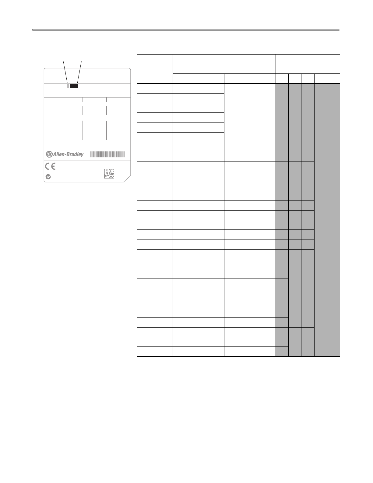
Chapter 2 Prepare for Installation
Cat No. 20G11 N D 011 AA0NNNNN
UL Type 1 - only with Debris Hood and Conduit Plate
UL Open Type/IP20 - without Debris Hood and Conduit Plate
Specifications and Custom Catalog Number
representing options installed at factory.
See Nameplate 2 (Located behind HIM)
for equivalent base catalog number and separate options
Nameplate 1:
Mfd. in 2009 on Jan. 19
Series: A
Input: 3 Phase, 47-63Hz
AC Voltage Range
Amps ND (HD)
Power ND (HD)
Output: 3 Phase, 0-400 Hz
AC Voltage Range
Base Frequency (default)
Continuous Amps ND (HD)
60Sec Ovld Amps ND (HD)
3 Sec Ovld Amps ND (HD)
0-400
50 Hz
342-440 432-528
0-460
60 Hz
xxx
xxx
xxx
xxx
xxx
xxx
xxx
xxx
xxx
xxx
xxx
xxx
xxx xxx xxx xxx
5.5 HP (4 HP) 7.5 HP (5 HP)
N223
Serial Number: xxxxxxxx
Original Firmware: x.xxx
Made in the U.S.A. Fac1C
400V Class 480V Class
➊ ➋
Drive Nameplate 1, Wall Mount Frames 1…7
➋➊
Drive Code
Input Voltage and ND Amp Rating Enclosure Code
600V AC 690V AC F G N R
20F or 20G E1P7 –
3 3 3 –
20F or 20G E2P7
20F or 20G E3P9
20F or 20G E6P1
20F or 20G E9P0
20F or 20G E011
20F or 20G E012 F012
– 6 6
20F or 20G E017 – 3 3 3
20F or 20G E018 F015
– 6 6
20F or 20G E022 – 3 3 3
20F or 20G E023 F020 – 6 6
20F or 20G E024 F023
20F or 20G E027 –
4 4 4
20F or 20G E028 F030 – 6 6
20F or 20G E032 –
4 4 4
20F or 20G E033 F034 – 6 6
20F or 20G E041 – 5 5 5
20F or 20G E042 F046
– 6 6
20F or 20G E052 – 5 – 5
20F or 20G E053 F050 6 6
20F or 20G E063 F061
20F or 20G E077 F082
20F or 20G E099 F098
20F or 20G E125 F119
20F or 20G E144 F142
20F or 20G E192 F171 7 7
20F or 20G E242 F212
20F or 20G E289 F263
Wall Moun t Frame
16 Rockwell Automation Publication 750-IN001O-EN-P - October 2014
Page 17
Floor Mount Frames 8…10
Cat No: 20G1A B D 430 JN0NNNNN
CM Cap Jumpers Installed
UL Type 1 / IP20 in 600 mm deep cabinet
Specifications and Custom Catalog Number
representing options installed at factory.
See Nameplate 2 (Located behind HIM)
for equivalent base catalog number and separate options
Nameplate 1:
MFD DATE: 2010/08/20
Series: B
Input: 3-Phase, 47-63 Hz
AC Voltage Range
Amps LD/ND/HD
Power LD/ND/HD
Auxillary Input Power: 120V//240V AC, 50/60Hz, 8.3A/4.2A, 1kVA
Output: 3-Phase, 0-400 Hz
AC Voltage Range
Base Freq. (default)
Cont. Amps LD/ND/HD
60S OL Amps LD/ND/HD
3S OL Amps LD/ND/HD
0-400
50 Hz
360-440 432-528
0-460
60 Hz
xxx/xxx/xxx
xxx/xxx/xxx
/xxx/xxx
xxx/xxx/xxx
xxx/xxx/xxx
/xxx/xxx
xxxx/xxxx/xxxx xxxx/xxxx/xxxx
315/250/200 (kW) 400/350/300 (HP)
N223
Serial Number: xxxxxxxx
Original Firmware: x.xxx
Product of U.S.A. FAC 1100
400V Class 480V Class
➊ ➋
Drive Nameplate 1, Floor Mount Frames 8…10
Drive Rating Cross-references
➋➊
Drive Code
Input Voltage and ND Amp Rating Enclosure Code
400V AC 480V AC 600V AC 690V AC B L, J P, K W, Y
20G or 21G C460 D430 E295 F265
20G or 21G C540 D485 E355 F330
20G or 21G C567 D545 E395 F370
20G or 21G C650 D617 E435 F415
20G or 21G C750 D710 E460 F460
20G or 21G C770 D740 E510 F500
20G or 21G C910 D800 E595 F590
20G or 21G C1K0 D960 E630 F650
20G or 21G C1K1 D1K0 E760 F710
20G or 21G C1K2 D1K2 E825 F765
20G or 21G C1K4 D1K3 E900 F795
20G or 21G C1K5 D1K4 E980 F960
20G or 21G C1K6 D1K5 E1K1 F1K0
20G or 21G C2K1 D2K0 E1K4 F1K4
Prepare for Installation Chapter 2
8 8 8 8
9 9 9 9
Floor Mount Frame
10 10 10 10
Rockwell Automation Publication 750-IN001O-EN-P - October 2014 17
Page 18

Chapter 2 Prepare for Installation
CE Conformity
Compliance with the Low Voltage Directive and Electromagnetic Compatibility
Directive has been demonstrated using harmonized European Norm (EN)
standards, referenced by the Official Journal of the European Union. PowerFlex
750-Series drives comply with the EN standards listed in this section when
installed according to these installation instructions.
EU Declarations of Conformity are available online at:
www.rockwellautomation.com/products/certification/
Low Voltage Directive
• EN 61800-5-1 Adjustable speed electrical power drive systems – Part 5-1:
Safety requirements – Electrical, thermal and energy.
EMC Directive
• EN 61800-3 Adjustable speed electrical power drive systems – Part 3:
EMC product standard including specific test methods.
General Considerations
• For EU compliance, drives must satisfy installation requirements that are
related to both EN 61800-5-1 and EN 61800-3 provided in this
document.
• PowerFlex 750-Series AC Drives comply with the EMC requirements of
EN 61800-3 when installed according to good EMC practices and the
instructions that are provided in this document. However, many factors
can influence the EMC compliance of an entire machine or installation,
and compliance of the drive itself does not ensure compliance of all
applications.
• PowerFlex 750-Series drives are not intended to be used on public lowvoltage networks that supply domestic premises. Without additional
mitigation, radio frequency interference is expected if used on such a
network. The installer is responsible to take measures such as
supplementary line filters and enclosures to prevent interference, in
addition to the installation requirements of this document.
ATTENTION: NEMA/UL Open Type and Flange Mount drives must either
be installed in a supplementary enclosure or equipped with a “NEMA
Type 1 Kit” to be CE-compliant with respect to protection against
electrical shock.
• Requirements for supplementary mitigation that is related to specific highfrequency emission limits are provided in Tabl e 1
.
18 Rockwell Automation Publication 750-IN001O-EN-P - October 2014
Page 19

Prepare for Installation Chapter 2
• PowerFlex 750-Series drives generate harmonic current emissions on the
AC supply system. When operated on a public low-voltage network it is
the responsibility of the installer or user to ensure that applicable
requirements of the distribution network operator have been met.
Consultation with the network operator and Rockwell Automation can be
necessary.
ATTENTION: PowerFlex 750-Series drives produce DC current in the
protective earthing conductor which can reduce the ability of RCDs
(residual current-operated protective devices) or RCMs (residual
current-operated monitoring devices) of type A or AC to provide
protection for other equipment in the installation. Where an RCD or
RCM is used for protection in case of direct or indirect contact, only an
RCD or RCM of Type B is allowed on the supply side of this product.
Installation Requirements Related to EN 61800-5-1 and the Low Voltage Directive
Frame 1 Drives
• Voltage classes up to 480V PowerFlex 750-Series Frame 1 drives can only
be used on a “center grounded” supply system for altitudes up to and
including 2000 m (6562 ft).
Frame 2 and Larger Drives
• Voltage classes up to 690V PowerFlex 750-Series Frame 2 and larger drives
are compliant with the CE LV Directive when used on a “corner-earthed”
supply system and all other common supply systems for altitudes up to and
including 2000 m (6562 ft).
• When used at altitudes above 2000 m (6562 ft) up to a maximum of
4800 m (15,748 ft), PowerFlex 750-Series drives of voltage classes up to
480V cannot be powered from a “corner-earthed” supply system to
maintain compliance with the CE LV Directive. Altitude derating curves
are provided in the PowerFlex 750-Series AC Drives Technical Data,
publication 750-TD001
.
Rockwell Automation Publication 750-IN001O-EN-P - October 2014 19
Page 20
Chapter 2 Prepare for Installation
All Drive Frames
• Drives that are provided in the IP54, NEMA/UL Type 12 enclosure are
compliant with the CE LV Directive when installed in pollution degree
1…4 environments. All other enclosure types must be installed in a
pollution degree 1 or 2 environment to be compliant with the CE LV
Directive. Characteristics of the different pollution degree ratings are
provided in the PowerFlex 750-Series AC Drives Technical Data,
publication 750-TD001
• PowerFlex 750-Series drives produce leakage current in the protective
earthing conductor that exceeds 3.5 mA AC and/or 10 mA DC. The
minimum size of the protective earthing (grounding) conductor that is
used in the application must comply with local safety regulations for highprotective earthing conductor current equipment.
ATTENTION: PowerFlex 750-Series drives produce DC current in the
protective earthing conductor which can reduce the ability of RCDs
(residual current-operated protective devices) or RCMs (residual
current-operated monitoring devices) of type A or AC to provide
protection for other equipment in the installation. Where an RCD or
RCM is used for protection in case of direct or indirect contact, only an
RCD or RCM of Type B is allowed on the supply side of this product.
.
20 Rockwell Automation Publication 750-IN001O-EN-P - October 2014
Page 21

Prepare for Installation Chapter 2
Installation Requirements Related to EN 61800-3 and the EMC Directive
• The drive must be earthed (grounded) as described in Power Wiring on
page 145.
• Output power wiring to the motor must employ cable with a braided
shield providing 75% or greater coverage, or the cables must be housed in
metal conduit, or equivalent shielding must be provided. Continuous
shielding must be provided from the drive enclosure to the motor
enclosure. Both ends of the motor cable shield (or conduit) must terminate
with a low-impedance connection to earth.
Wall Mount Drive Frames 1…7: At the drive end of the motor cable, either
a. The cable shield must be clamped to a properly installed “EMC plate”
for the drive. Kit number 20-750-EMC1-Fx.
or
b. The cable shield or conduit must terminate in a shielded connector that
is installed in a conduit plate or conduit box that is provided in the
“NEMA Type 1 Kit” for the drive (kit number 20-750-NEMA1-Fx).
Floor Mount Drive Frames 8 and larger: At the drive end of the motor
cable, terminate the shield at the PE Grounding Bar (See page 156
• At the motor end, the motor cable shield or conduit must terminate in a
shielded connector which must be properly installed in an earthed motor
wiring box that is attached to the motor. The motor-wiring box cover must
be installed and earthed.
• All control (I/O) and signal wiring to the drive must use cable with a
braided shield providing 75% or greater coverage, or the cables must be
housed in metal conduit, or equivalent shielding must be provided. When
shielded cable is used, the cable shield is terminated with a low-impedance
connection to earth at only one end of the cable, preferably the end where
the receiver is located. When the cable shield is terminated at the drive
end, it can be terminated either by using a shielded connector with a
conduit plate or conduit box, or the shield can be clamped to an “EMC
plate.”
• Motor cables must be separated from control and signal wiring wherever
possible.
• Maximum motor-cable length must not exceed the maximum length that
is indicated in Ta ble 1
limits for the specific standard and installation environment.
• EMC cores must be applied to input power and motor cables for some
models of the PowerFlex 750-Series drives as indicated in Tab le 1
• The drive must be powered from an earthed supply system such as a TN or
TT system and the PE-A and PE-B jumpers in the drive must be installed
(see Drive Power Jumper Configuration
• IP00 and NEMA/UL Open Type Frame 8 and higher frames must be
installed in suitable supplementary EMC enclosures to achieve compliance
with EN 61800-3.
for compliance with radio-frequency emission
on page 209).
).
.
Rockwell Automation Publication 750-IN001O-EN-P - October 2014 21
Page 22

Chapter 2 Prepare for Installation
Table 1 - PowerFlex 750-Series 400/480V Input Drives RF Emission Compliance and Installation
Requirements
Standard / Limits
Drive Frame
Catalog Number
Wall Mount Frame 1
20F11xx2P1…20F11xx015
EN61800-3 Category C1
EN61000-6-3
CISPR11 Group 1 Class B
EN61800-3 Category C2
EN61000-6-4
CISPR11 Group 1 Class A
(Input Power
≤ 20 kVA)
N/A 30 m motor cable limit with each wire
looped once around an input core.
EN61800-3 Category C3
(I
≤ 100 A)
CISPR11 Group 1 Class A
(Input Power > 20 kVA)
30 m motor cable limit with each wire
(1) (2)
looped once around an input core.
20G11xx2P1…20G11xx015
Wall Mount Frame 2
20F11xx2P1…20F11xx022
20G11xx2P1…20G11xx022
Wall Mount Frame 3
20F11xx030…20F11xx043
20G11xx030…20G11xx043
Wall Mount Frame 4
20F11xx060…20F11xx072
20G11xx060…20G11xx072
Wall Mount Frame 5
20F11xx085…20F11xx104
20G11xx085…20G11xx104
150 m cable limit with Schaffner
FN3258-30-nn filter.
Supplementary EMC enclosure is
required to provide attenuation of
radiated emissions.
150 m cable limit with Schaffner
FN3258-55-nn filter.
Supplementary EMC enclosure is
required to provide attenuation of
radiated emissions.
150 m cable limit with Schaffner
FN3258-75-nn filter.
Supplementary EMC enclosure is
required to provide attenuation of
radiated emissions.
150 m cable limit with Schaffner
FN3258-130-nn filter.
Supplementary EMC enclosure is
required to provide attenuation of
30 m motor cable limit with input core.
(1)
150 m motor cable limit with Schaffner
FN3258-30-nn filter.
30 m motor cable limit with input core.
(1)
150 m motor cable limit with Schaffner
FN3258-55-nn filter.
30 m motor cable limit with input and
output cores.
150 m motor cable limit with Schaffner
FN3258-75-nn filter.
30 m motor cable limit with input and
output cores.
150 m motor cable limit with Schaffner
FN3258-130-nn filter.
(1)
(1)
30 m motor cable limit with input core.
(1)
150 m motor cable limit with Schaffner
FN3258-30-nn filter.
30 m motor cable limit with input core.
(1)
150 m motor cable limit with Schaffner
FN3258-55-nn filter.
30 m motor cable limit with input and
output cores.
150 m motor cable limit with Schaffner
FN3258-75-nn filter.
30 m motor cable limit with input and
output cores.
150 m motor cable limit with Schaffner
FN3258-130-nn filter.
(1)
(1)
radiated emissions.
Wall Mount Frame 6
20F11xx140…20F11xx260
20G11xx140…20G11xx260
Wall Mount Frame 7
20F11xx302…20F11xx456
20G11xx302…20G11xx456
Floor Mount Frame 8 - AC Input
20G1Axx460…20G1Axx770
21G1Axx460…21G1Axx770
Floor Mount Frame 9 - AC Input
20G11xx910…20G11xx1K5
21G11xx910…21G11xx1K5
Floor Mount Frame 10 - AC Input
20G11xx1K6…20G11xx2K1
21G11xx1K6…21G11xx2K1
Floor Mount Frames 8…9 Common DC Input
20G14xx460…20G14xx1K5
150 m cable limit with 22-RFD323
filter.
Supplementary EMC enclosure is
required to provide attenuation of
radiated emissions.
150 m cable limit with 22-RFD480
filter.
Supplementary EMC enclosure is
required to provide attenuation of
radiated emissions.
Compliance possible with
supplementary mitigation
(Consult factory)
Compliance possible with
supplementary mitigation
(Consult factory)
Compliance possible with
supplementary mitigation
(Consult factory)
Compliance possible with
supplementary mitigation
(Consult factory)
100 m motor cable limit with Schaffner
FN3359-320-nn filter.
150 m motor cable limit with 22RFD323 filter.
Supplementary EMC enclosure is
required to provide attenuation of
radiated emissions.
150 m motor cable limit with Schaffner
FN3359-600-nn filter.
150 m motor cable limit with 22RFD480 filter.
Supplementary EMC enclosure is
required to provide attenuation of
radiated emissions.
Compliance possible with
supplementary mitigation
(Consult factory)
Compliance possible with
supplementary mitigation
(Consult factory)
Compliance possible with
supplementary mitigation
(Consult factory)
Compliance possible with
supplementary mitigation
(Consult factory)
30 m motor cable limit with no filter.
100 m motor cable limit with Schaffner
FN3359-320-nn filter.
150 m motor cable limit with 22-
RFD323 filter.
30 m motor cable limit with no filter.
150 m motor cable limit with Schaffner
FN3359-600-nn filter.
150 m motor cable limit with 22RFD480 filter.
(3)
30 m motor cable limit
(4)
core.
30 m motor cable limit
(4)
and input core.
core
30 m motor cable limit
(4)
and input core. With door
core
shielding kit installed.
30 m motor cable limit
(4)
and input core.
core
with output
(3)
with output
(3)
with output
(5)
(3)
with output
(6)
21G14xx460…21G14xx1K5
Floor Mount Frame 10 - Common
DC Input
20G14xx1K6…20G14xx2K1
Compliance possible with
supplementary mitigation
(Consult factory)
Compliance possible with
supplementary mitigation
(Consult factory)
30 m motor cable limit
(4)
core
and input core.
shielding kit installed.
(3)
with output
(6)
With door
(5)
21G14xx1K6…21G14xx2K1
More Stringent Limits Less Stringent Limits
(1) Rating-specific EMC cores are part of EMC kit numbers 20-750-EMC1-nn and 20-750-EMC2-nn.
(2) To meet the C2 rating with a Dual Encoder module installed, Frame 1 drives must be installed in a supplementary EMC enclosure to attenuate radiated emissions.
(3) Intended to be powered from an industrial power network that is supplied by a dedicated power transformer or generator and not from LV power lines that supply other customers.
(4) EMC kit number 20-750-EMCCM1-F8. Kit contains one core. Each drive assembly requires one EMC kit. Order one kit for a Frame 8 drive, two kits for a Frame 9 drive, three kits for a Frame 10 drive.
(5) Door-shielding kit number 20-750-EMCDK1-F10. Kit contains shield brackets for three doors.
(6) EMC kit number 20-750-CBPEMCCM1-F8. Kit contains one core. Each drive assembly requires one EMC kit. Order one kit for a Frame 8 drive, two kits for a Frame 9 drive, three kits for a Frame 10 drive.
EN61800-3 Category C3
I > 100 A
N/A
(1)
N/A
N/A
N/A
30 m motor cable limit with input and
output cores.
150 m motor cable limit with Schaffner
FN3258-130-nn filter.
(3)
30 m motor cable limit with no filter.
100 m motor cable limit with Schaffner
FN3359-320-nn filter.
150 m motor cable limit with 22-
RFD323 filter.
(3)
30 m motor cable limit with no filter.
150 m motor cable limit with Schaffner
FN3359-600-nn filter.
(1)
150 m motor cable limit with 22RFD480 filter.
30 m motor cable limit
(4)
core.
30 m motor cable limit
(4)
and input core.
core
30 m motor cable limit
(4)
and input core. With door
core
shielding kit installed.
30 m motor cable limit
(4)
and input core.
core
30 m motor cable limit
(4)
core
and input core. With door
shielding kit installed.
(3)
with output
(3)
with output
(3)
with output
(5)
(3)
with output
(6)
(3)
with output
(5)
(3)
(3)
22 Rockwell Automation Publication 750-IN001O-EN-P - October 2014
Page 23
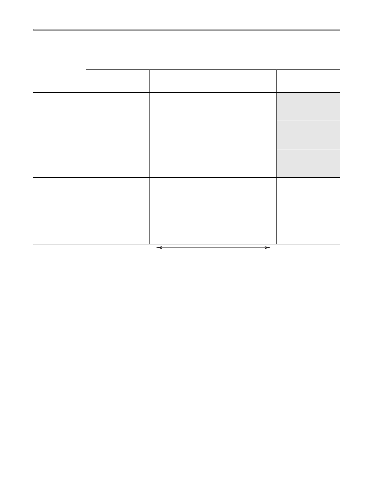
Table 2 - PowerFlex 750-Series 600/690V Input Drives RF Emission Compliance and Installation
Requirements
Drive Frame
Catalog Number
Wall Mount Frame 3: 600V (3
Hp and higher.)
20F11xE3P9…20F11xE022
20G11xE3P9…20G11xE022
Wall Mount Frame 4: 600V
20F11xE027…20F11xE032
20G11xE027…20G11xE032
Wall Mount Frame 5: 600V
20F11xE041…20F11xE052
20G11xE041…20G11xE052
Wall Mount Frame 6: 600/690V
20F11xx012…20F11xx144
20G11xx012…20G11xx144
Frame 7: 600/690
20F11xx192…20F11xx289
20G11xx192…20G11xx289
(1) Rating-specific EMC cores are part of EMC kit numbers 20-750-EMC3-nn and 20 -750-EMC4-nn.
EN61800-3 Category C1
EN61000-6-3
CISPR11 Group 1 Class B
50 m cable limit with Schaffner
FN258HV-42-33 filter.
Supplementary EMC enclosure is
required to provide attenuation of
radiated emissions.
50 m cable limit with Schaffner
FN258HV-55-34 filter.
Supplementary EMC enclosure is
required to provide attenuation of
radiated emissions.
50 m cable limit with Schaffner
FN258HV-100-35 filter.
Supplementary EMC enclosure is
required to provide attenuation of
radiated emissions.
50 m cable limit with Schaffner
FN258HV-100-35 filter (up to 90 kW
drives) or FN3359HV-250-28 filter
(110 kW and larger drives).
Supplementary EMC enclosure is
required to provide attenuation of
radiated emissions.
50 m cable limit with Schaffner
FN3359HV-400-99 filter.
Supplementary EMC enclosure is
required to provide attenuation of
radiated emissions.
More Stringent Limits Less Stringent Limits
EN61800-3 Category C2
EN61000-6-4
CISPR11 Group 1 Class A
(Input Power
30 m motor cable limit with one input
and one output core.
30 m motor cable limit with one input
and one output core.
30 m motor cable limit with one input
and one output core.
50 m cable limit with Schaffner
FN258HV-100-35 filter (up to 90 kW
drives) or FN3359HV-250-28 filter
≤ 20 kVA)
(110 kW and larger drives).
Supplementary EMC enclosure is
required to provide attenuation of
radiated emissions.
50 m cable limit with Schaffner
FN3359HV-400-99 filter.
Supplementary EMC enclosure is
required to provide attenuation of
radiated emissions.
(1)
(1)
(1)
Standard / Limits
EN61800-3 Category C3
(I
≤ 100 A)
CISPR11 Group 1 Class A
(Input Power > 20 kVA)
30 m motor cable limit with one input
and one output core.
30 m motor cable limit with one input
and one output core.
30 m motor cable limit with one input
and one output core.
30 m motor cable limit with one input
and one output core.
30 m motor cable limit with one input
and one output core.
Prepare for Installation Chapter 2
EN61800-3 Category C3
I > 100 A
(1)
(1)
(1)
(1)
(1)
N/A
N/A
N/A
30 m motor cable limit with one input
and one output core.
30 m motor cable limit with one input
and one output core.
(1)
(1)
Rockwell Automation Publication 750-IN001O-EN-P - October 2014 23
Page 24
Chapter 2 Prepare for Installation
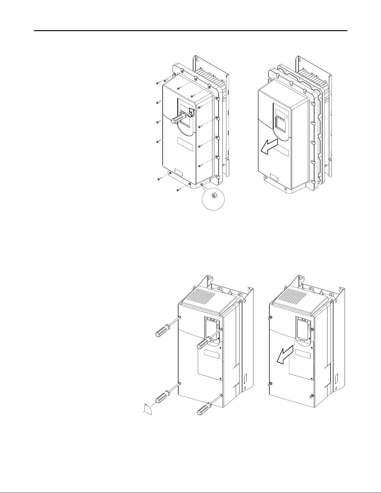
Access Panels, Covers, and Doors
Figure 1 - Enclosure Code R (IP20, NEMA/UL Open Type) Wall Mount Frame 1
Figure 2 - Enclosure Code N (IP20, NEMA/UL Open Type) Wall Mount Frames 2…5
24 Rockwell Automation Publication 750-IN001O-EN-P - October 2014
Page 25
Prepare for Installation Chapter 2
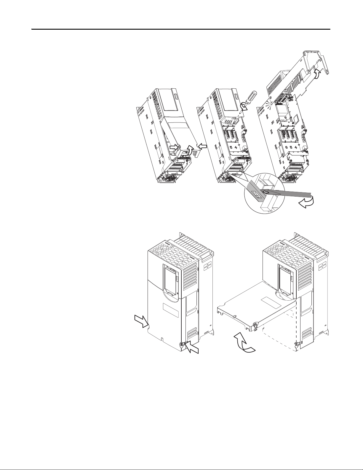
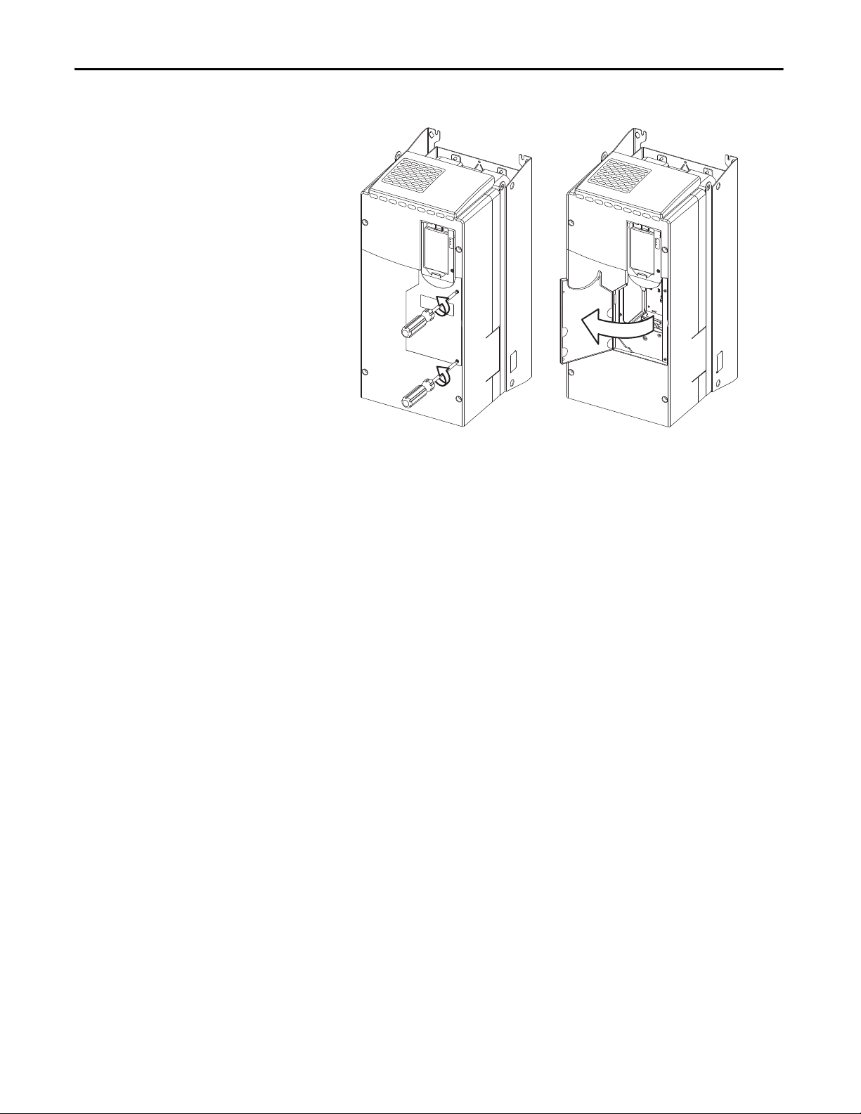
Figure 3 - Enclosure Code G (IP54, NEMA/UL Type 12) Wall Mount Frames 2…5
2x:
M4 X 0.7
When cover is replaced:
• Recommended torque (screws and nuts) = 0.68 N•m (6.0 lb•in)
• Recommended screwdriver = 6.4 mm (0.25 in.) flat or T20 Hexalobular
• Recommended hex socket = 7 mm
Figure 4 - Enclosure Code N (IP00, NEMA/UL Open Type) Wall Mount Frames 6 and 7
90°
When cover is replaced:
• Recommended screwdriver = 9.5 mm (0.375 in.) flat
Rockwell Automation Publication 750-IN001O-EN-P - October 2014 25
Page 26
Chapter 2 Prepare for Installation
Figure 5 - Enclosure Code N (IP00, NEMA/UL Open Type) Wall Mount Frames 6 and 7 Access Door
When door is replaced:
• Recommended screwdriver = 6.4 mm (0.25 in.) flat or T20 Hexalobular
26 Rockwell Automation Publication 750-IN001O-EN-P - October 2014
Page 27
Prepare for Installation Chapter 2
90°
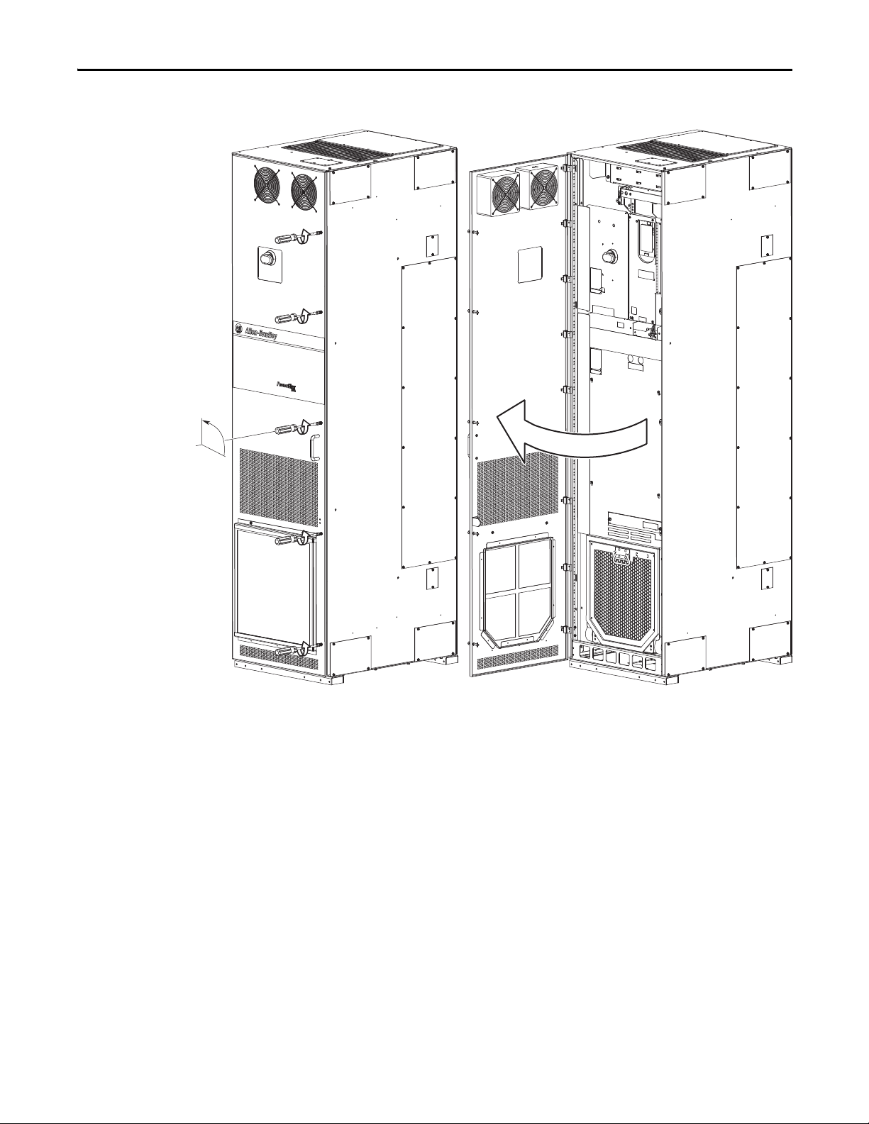
Figure 6 - Floor Mount Frames 8 and Larger Cabinet Access Door (All Enclosure Types)
To release or secure door:
• Recommended screwdriver = 9.5 mm (0.375 in.) flat
Rockwell Automation Publication 750-IN001O-EN-P - October 2014 27
Page 28
Chapter 2 Prepare for Installation
➊
➋
➌
➎
➍
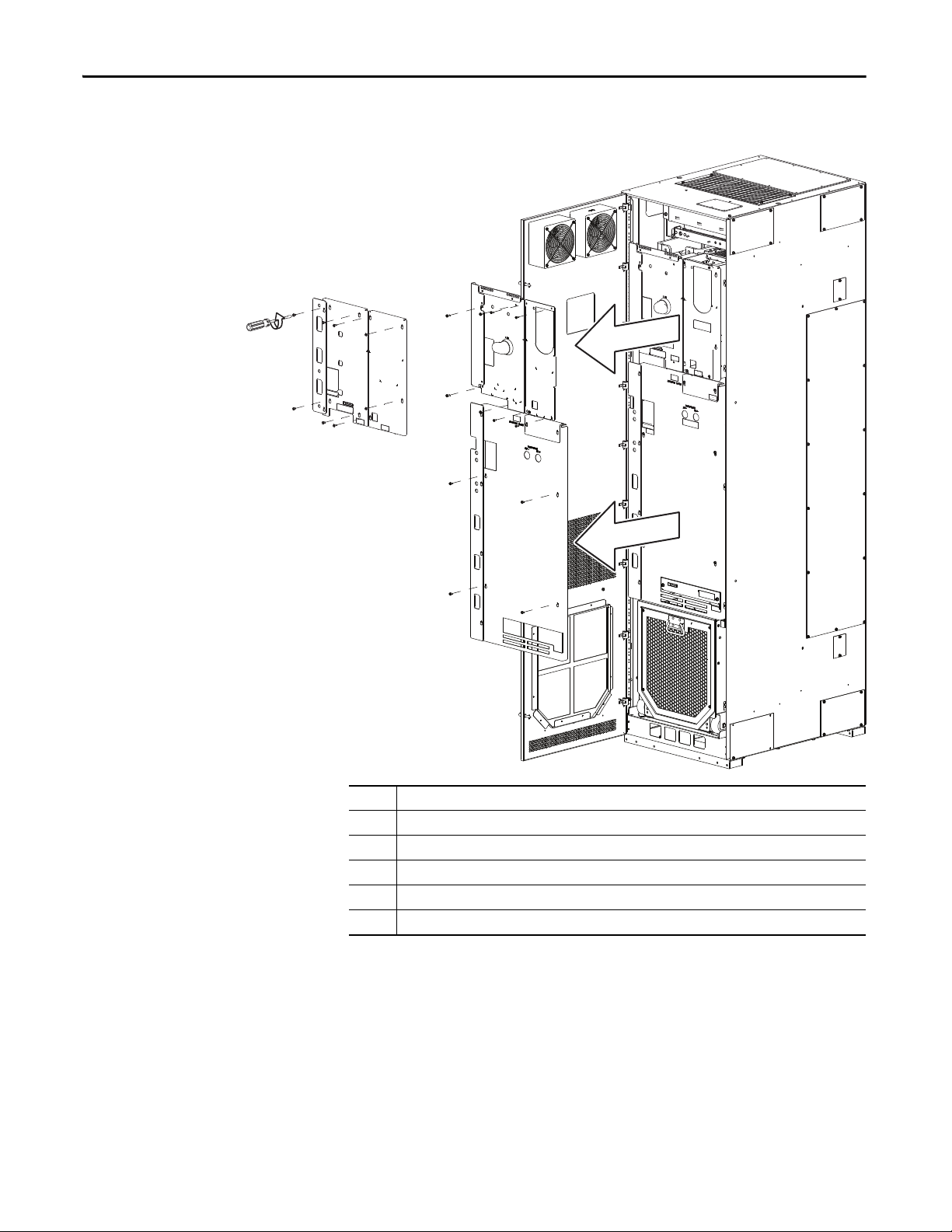
Figure 7 - Floor Mount Drive-assembly Access Panels - All Enclosure Types (IP20, NEMA/UL Type 1
Shown)
No. Description
➊ Lef t Front Conve rter Cover with Side Shiel d (AC Input Drives)
➋ Right Front Converter Cover (No Control Pod)
➌ Lef t Front Conver ter Cover with Side Shie ld (Common DC Input Drives)
➍ Right Front Converter Cover (With Control Pod)
➎ Inverter Front Cover with Side Shield (Common DC Input Drives)
When covers are replaced:
• Recommended torque = 2.8 N•m (25.0 lb•in)
• Recommended screwdriver = 6.4 mm (0.25 in.) flat or T25 Hexalobular
28 Rockwell Automation Publication 750-IN001O-EN-P - October 2014
Page 29
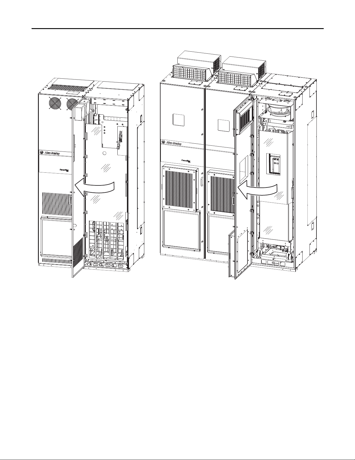
Figure 8 - Floor Mount Cabinet Options Bay Access Door
Floor Mount Frame 8 - IP20, NEMA/UL Type 1 Floor Mount Frame 9 - IP54, NEMA 12
Prepare for Installation Chapter 2
To release or secure door:
• Recommended screwdriver = 9.5 mm (0.375 in.) flat
Rockwell Automation Publication 750-IN001O-EN-P - October 2014 29
Page 30
Chapter 2 Prepare for Installation
Figure 9 - Full Cabinet Options Bay Guard - Floor Mount Frame 8
To remove the full bay guard, loosen the ten M5 screws. It is not necessary to
remove these screws.
When the full bay guard is replaced:
• Recommended torque = 2.8 N•m (25.0 lb•in)
• Recommended driver = 8 mm Hexagonal socket
30 Rockwell Automation Publication 750-IN001O-EN-P - October 2014
Page 31

Figure 10 - Full Cabinet Options Bay Guard Floor Mount Frame 9
Prepare for Installation Chapter 2
To remove the full bay guard, loosen the ten M5 screws. It is not necessary to
remove these screws.
When the full bay guard is replaced:
• Recommended torque = 2.8 N•m (25.0 lb•in)
• Recommended driver = 8 mm Hexagonal socket
Rockwell Automation Publication 750-IN001O-EN-P - October 2014 31
Page 32

Chapter 2 Prepare for Installation
Airflow through the drive
must not be impeded.
860 mm
(33.9 in.)
860 mm
(33.9 in.)
20-750-CART1-F8
182 mm (7.2 in.)
Airflow through the drive must not be impeded.
IP20, NEMA/UL Type 1
IP54, NEMA 12
IP20, NEMA/UL Type 1
with Optional Exhaust Hood
Minimum Clearances
Specified vertical clearance requirements (indicated in Figure 11) are intended to
be from the drive to the closest object that can restrict airflow through the drive
heat sink and chassis. The drive must be mounted in a vertical orientation as
shown and must make full contact with the mounting surface. Do not use
standoffs or spacers. In addition, inlet air temperature must not exceed the
product specification.
Figure 11 - Minimum Mounting Clearances – Wall Mount Frames 1…7
76.2 mm (3.0 in.)
76.2 mm (3.0 in.)
Figure 12 - Minimum Mounting Clearances – Floor Mount Drive Cabinets
32 Rockwell Automation Publication 750-IN001O-EN-P - October 2014
Page 33

Prepare for Installation Chapter 2
Mounting Considerations
Environmental Specifications
Wall Mount Frames 1…7
• Mount the drive upright on a flat, vertical, and level surface.
• Verify that the drive is in full contact with the mounting surface as
depicted in Figure 11
.
Floor Mount Frames 8…10
• Install the drive upright on a flat and level surface.
• Verify that the drive cabinet is square, vertical, and stable.
• Verify that the filter and debris screens are installed.
All Mounting Styles and Frames
• Protect the cooling fan by avoiding dust or metallic particles.
• Do not expose to a corrosive atmosphere.
• Protect from moisture and direct sunlight (unless rated for outdoor use).
Maximum Surrounding Air Temperature
IP20, NEMA/UL Open Type:
IP00, NEMA/UL Open Type:
IP20, NEMA/UL Type 1 (w/Hood):
IP20, NEMA/UL Type 1 (w/Label):
IP20, NEMA/UL Type 1 (MCC Cabinet):
IP54, NEMA 12 (MCC Cabinet):
Flange Mount –
Front:
IP20, NEMA/UL Open Type:
IP00, NEMA/UL Open Type:
Back/Heat Sink:
IP66, NEMA/UL Type 4X
Stand-alone/Wall Mount –
IP54, NEMA/UL Type 12
Storage Temperature (all const.): -40…70 °C (-40…158 °F)
Atmosphere: Important: Drive must
0…50 °C (32…122 °F)
0…50 °C (32…122 °F)
0…40 °C (32…104 °F)
0…40 °C (32…104 °F)
0…40 °C (32…104 °F)
0…40 °C (32…104 °F)
0…50 °C (32…122 °F)
0…50 °C (32…122 °F)
0…40 °C (32…104 °F)
0…40 °C (32…104 °F)
atmosphere contains volatile or corrosive gas, vapors, or dust. If the drive
is not going to be immediately installed, it must be stored in an area
where it is not exposed to a corrosive atmosphere.
Wall Mount Frames 1…5, All Ratings
Wall Mount Frames 6…7, All Ratings
Wall Mount Frames 1…5, All Ratings
Wall Mount Frames 6…7, All Ratings
Floor Mount Frames 8…10, All Ratings
Floor Mount Frames 8…10, All Ratings
Wall Mount Frames 2…5, All Ratings
Wall Mount Frames 6…7, All Ratings
Wall Mount Frames 2…7, All Ratings
Wall Mount Frames 2…7, All Ratings
not be installed in an area where the ambient
Rockwell Automation Publication 750-IN001O-EN-P - October 2014 33
Page 34

Chapter 2 Prepare for Installation
Notes:
34 Rockwell Automation Publication 750-IN001O-EN-P - October 2014
Page 35

Lift and Mount the Drive
Chapter 3
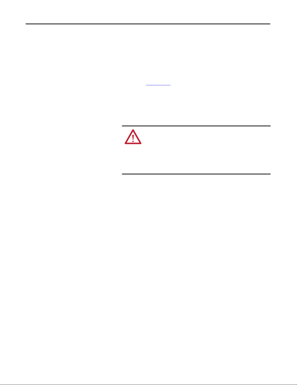
Drive Weights
Drive Frame
Standard
(20F, 20G)
Standard
(20G)
with
Options
(21G)
AC Input
and Common
DC Input
AC Input 8 250…400 350…650 623 (1374) 1145 (2525) 644 (1419) 1166 (2570)
Common DC
Input
AC Input 8 250…400 350…650 1145 (2525) 1675 (3694) 1166 (2570) 1696 (3739)
Size
1 0.75…7.5 1…10
2 0.75…11 1…15 8 (17) 8 (17) 8 (17)
3 15…22 0.5…30 12 (26) 12 (26) 12 (26)
4 30…37 20…50 14 (30) 14 (30) 14 (30)
5 45…55 30…70 20 (45) 20 (45) 20 (45)
6 5.5…75 75…100 37 (82) 89 (197) 37 (82)
7 132…200 150…300 69 (152) 135 (297) 79 (174)
9 500…850 700…1250 1246 (2748) 2290 (5051) 1287 (2838) 2332 (5141)
10 900…1250 1350…1750 1869 (4122) 3435 (7576) 1931 (4257) 3498 (7711)
8 250…400 350…650 566 (1248) 1088 (2400) 586 (1293) 1109 (2445)
9 500…850 700…1250 1132 (2497) 2176 (4799) 1173 (2587) 2218 (4889)
10 900…1250 1350…1750 1698 (3745) 3264 (7199) 1760 (3880) 3327 (7334)
9 500…850 700…1250 1730 (3815) 2820 (6219) 1771 (3905) 2862 (6309)
10 900…1250 1350…1750 2315 (5106) 3965 (8745) 2377 (5241) 4028 (8880)
All lifting equipment and lifting components (hooks, bolts, lifts, slings, chains,
and so forth) must be properly sized and rated to safely lift and hold the weight of
the drive while mounting.
ATTENTION: To guard against possible personal injury and/or equipment
damage…
• Inspect all lifting hardware for proper attachment before lifting drive.
• Do not allow any part of the drive or lifting mechanism to make contact with
electrically charged conductors or components.
• Do not subject the drive to high rates of acceleration or deceleration while
transporting to the mounting location or when lifting.
• Do not allow personnel or their limbs directly underneath the drive when it is
being lifted and mounted.
Table 3 - Approximate Drive Weights - Wall Mount Frames 1…7 and Floor Mount Frames 8…10
Drive Rating Enclosure Code/Weight kg (lb)
kW (400V, 690V) Hp (480V, 600V) FGNR
6 (13)
45…132 50…200 38 (84) 91 (200) 39 (85)
200…250 300…350 96 (212) 162 (357) 106 (234)
B, L P, W J K, Y
Rockwell Automation Publication 750-IN001O-EN-P - October 2014 35
Page 36

Chapter 3 Lift and Mount the Drive
IMPORTANT
Recommended Mounting Hardware
Table 4 - Maximum Component Weights - Floor Mount Frames 8…10
Component Weight kg (lb)
AC Input Common DC Input
Converter/DC Input w/Precharge 64 (140) 64 (140)
Inverter 222 (490) 165 (363)
Drive Assembly (Open, IP00) 286 (630) 229 (504)
Cabinet Options Assembly with Circuit Breaker and Reactor 296 (653) –
Frame Size Fastener Size Notes
1
2
M6 (#10 or #12)
M12 (1/2 in.) Property Class 8.8 (Minimum)9
Wall Mount
Floor Mou nt
3
4
5
6 M6 (#12)
7M8 (5/16 in.)
8
10
Mounting hardware is provided with enclosure type F (Flange mount) drives.
The hardware supplied must be used to meet the enclosure rating.
36 Rockwell Automation Publication 750-IN001O-EN-P - October 2014
Page 37

Lift and Mount the Drive Chapter 3
>
1
/
2 A
A
<45°
>
1
/
2 A
A
<45°
Attach Lifting Hardware
Figure 13 - Rigging Geometry
Enclosure Code F
Wall Mount Frame 6 Lifting Points – 2 Places
Wall Mount Frame 7 Lifting Points – 4 Places
Rockwell Automation Publication 750-IN001O-EN-P - October 2014 37
Page 38

Chapter 3 Lift and Mount the Drive
Enclosure Code N
Wall Mount Frame 6 Lifting Points – 6 Places
Wall Mount Frame 7 Lifting Points – 8 Places
Enclosure Code G
Wall Mount Frames 6 and 7 Lifting Points – 4 Places
38 Rockwell Automation Publication 750-IN001O-EN-P - October 2014
Page 39

Lift and Mount the Drive Chapter 3
Open Type Drive (Removed From Cabinet)
Floor Mount Drive Assembly – IP00, NEMA/UL Type Open Drive Lifting Points – 2 Places
Enclosure Codes B and L
Floor Mount Frame 8 Lifting Points – 2 Places
Rockwell Automation Publication 750-IN001O-EN-P - October 2014 39
Page 40

Chapter 3 Lift and Mount the Drive
Floor Mount Frames 9 and 10 Lifting Points – 2 Places
Enclosure Codes J, K, and Y
Floor Mount Frame 9 with Cabinet Options Bay Lifting Points – 2 Places
40 Rockwell Automation Publication 750-IN001O-EN-P - October 2014
Page 41

Lift and Mount the Drive Chapter 3
IMPORTANT
Release Floor Mount Drive Cabinet From Shipping Skid
Remove the bolts fastening a vertically oriented drive cabinet to the shipping skid
and lift.
<45°
1
/
>
2 A
A
<45°
1
/
>
2 A
A
M10 x 25
17 mm
Remove the shipping crate that encloses a horizontally oriented drive cabinet on
the shipping skid and lift.
Drives equipped with the MCC bus option, with codes P20, P22, and P24 in the
catalog string, are not to be shipped horizontally.
Rockwell Automation Publication 750-IN001O-EN-P - October 2014 41
Page 42

Chapter 3 Lift and Mount the Drive
Floor Mou nt Frame 8
Floor Mou nt Frame 9
Floor Mou nt Frame 10
Remove Drive Cabinet Lifting Angle
After the drive cabinet is in its final position, remove the lifting angle.
M12
67.8 N•m (600 lb•in)
18 mm
42 Rockwell Automation Publication 750-IN001O-EN-P - October 2014
Page 43

Lift and Mount the Drive Chapter 3
Debris Screen (Supplied) Exhaust Hood (Optional Kit)
Install IP20, NEMA/UL Type 1 Debris Screen or Optional Exhaust Hood
IP20, NEMA/UL Type 1 drives are equipped with a top mounted debris screen.
An optional exhaust hood is also available as a kit (20-750-HOOD1-F8).
1. Install the supplied debris screen over the exhaust vent.
or
Install the optional exhaust hood with the grill facing the front of the drive.
2. Secure with the four screws provided.
T25
4.0 N•m (35 lb•in)
Install IP54, NEMA 12 Cabinet Blower Assembly and Exhaust Hood
IP54, NEMA 12 drives are equipped with top a mounted blower assembly and
exhaust hood.
1. Install the cabinet blower assembly. Note the required power connection.
2. Secure with the ten screws provided.
3. Install the exhaust hood with the grill facing the front of the drive.
4. Secure with the four screws provided.
T25
4.0 N•m (35 lb•in)
Rockwell Automation Publication 750-IN001O-EN-P - October 2014 43
Page 44

Chapter 3 Lift and Mount the Drive
Drive Cabinets
Cabinet Options Bay
IP54, NEMA 12 Enclosure Rating Shown
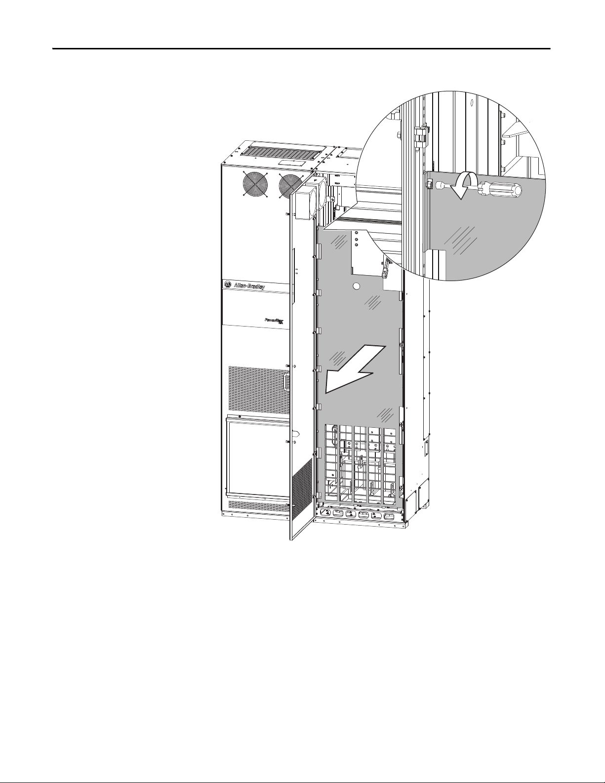
Install Floor Mount Drive with Cabinet Options Bay and Wiring Bay
Frame 9 drives configured with both the cabinet options bay and wiring bay ship
in two sections. The following procedure describes how to join the wiring bay to
the cabinet options bay.
1. Remove external wrapping, bus bar cover, and locate joining hardware.
Joining hardware is shipped with the wiring bay.
Description Quantity Description Quantity
M8 x 16 mm Cabinet Joining Screw 20 M10 Nut with Washer 12
M10 x 45 mm Carriage Bolt 12 M6 x 40 mm bolts 4
Bus Bar Clamp Plate 12 M6 Flange Nuts 4
Position the Drive Cabinets and Cabinet Options Bay
2. Release the factory-assembled drive cabinets and cabinet options bay from
the shipping skid.
M8 x 16
13 mm
44 Rockwell Automation Publication 750-IN001O-EN-P - October 2014
Page 45

3. Attach lifting hardware to the drive assembly.
IP54, NEMA 12 Enclosure Rating Shown
Lift and Mount the Drive Chapter 3
Follow lifting instructions and precautions beginning on page 35
.
4. Locate the factory-assembled drive cabinets and cabinet options bay in its
final position.
5. Remove and discard the seven M8 sealing screws from the right side of the
cabinet options bay.
M8
13 mm
Rockwell Automation Publication 750-IN001O-EN-P - October 2014 45
Page 46

Chapter 3 Lift and Mount the Drive
M6 x 13
10 mm
IP54, NEMA 12 Enclosure Rating Shown
Position the Wiring Bay
6. Remove and discard the screws holding the protective panel against the
left side of the wiring bay.
7. Remove and discard the protective panel.
46 Rockwell Automation Publication 750-IN001O-EN-P - October 2014
Page 47

Lift and Mount the Drive Chapter 3
M6 x 25
T30
Wiring B ay
3/8 in.
9/16 in.
M8 x 16
13 mm
8. Remove and discard the wiring bay inner panels covering the ends of the
bus bars.
9. Release the wiring bay from the shipping skid.
The shipping angles on the left side of the cabinet can be left in place to
assist with alignment in step 11
. Remove the shipping angles after cabinets
are aligned and joined.
Rockwell Automation Publication 750-IN001O-EN-P - October 2014 47
Page 48

Chapter 3 Lift and Mount the Drive
➊
➊
➋
➋
➋
10. Align the wiring bay with cabinet options bay.
11. Bring the cabinets together ➊.
The bus bar couplers extend from the cabinet options cabinet ➋ and align
with the bus bars in the wiring bay.
48 Rockwell Automation Publication 750-IN001O-EN-P - October 2014
Page 49

Lift and Mount the Drive Chapter 3
IMPORTANT
Join the Cabinets
12. Pass the M8 x 16 mm hex-head thread-forming screws from inside the
wiring bay through the clearance holes and start to engage the screws with
the holes in the cabinet options bay.
Make sure the cabinets are level and aligned and pushed tightly together.
13. Lightly tighten the screws in a uniform pattern.
Do not use hardware to draw cabinets together.
Torque screws labeled ➊ to 11.3 N•m (100 lb•in).
Torque screws labeled ➋ to 9.0 N•m (80 lb•in).
600
(23.6)
800
(31.5)
➊
➊
➊
➊
➊
➊
➊➊
➋
➋
➋
➊
➊
➊
➊
➊
➊
➊
➊
➊➊ ➊
➋
➋
➋
➋
➊
➊ ➊ ➊ ➊ ➊ ➊
Rockwell Automation Publication 750-IN001O-EN-P - October 2014 49
Page 50

Chapter 3 Lift and Mount the Drive
IMPORTANT
M10 x 1.5
38.0 N•m (336 lb•in)
17 mm
➋
➊
14. Remove the left most L-bracket from each of the six wiring bay bus bars to
access the channel notches.
17 mm
15. Insert the 12 carriage bolt assemblies ➊ into the 12 wiring bay bus bar
channels.
16. Slide the carriage bolt assemblies ➋ into the bus bar couplers on the left
and tighten.
50 Rockwell Automation Publication 750-IN001O-EN-P - October 2014
Verify that clamp fits squarely in the bus bar
channel.
Page 51

Lift and Mount the Drive Chapter 3
17. Use the M6 x 40 bolts and flange nuts to secure the upper and lower PE
bus bars to the cabinet bracket.
M6-40
7.3 N•m (65 lb•in)
10 mm
18. Reinstall the L-brackets removed in step 14
Refer to pages 162
…166 for torque requirements and addition L-bracket
and wiring details.
.
Rockwell Automation Publication 750-IN001O-EN-P - October 2014 51
Page 52

Chapter 3 Lift and Mount the Drive
Approximate Dimensions Wall Mount Frames 1…7 and
Floor Mount Frames 8…10
Table 5 - Dimension Drawing Index
Frame Description Page
1 IP20, NEMA/UL Open Type 53
2 IP20, NEMA/UL Open Type 53
IP54, NEMA/UL Type 12 54
IP54, NEMA/UL Type 12, Bottom Access 55
Flange Mount 56
3 IP20, NEMA/UL Open Type 53
IP54, NEMA/UL Type 12 54
IP54, NEMA/UL Type 12, Bottom Access 55
Flange Mount 57
4 IP20, NEMA/UL Open Type 53
IP54, NEMA/UL Type 12 54
IP54, NEMA/UL Type 12, Bottom Access 55
Flange Mount 58
5 IP20, NEMA/UL Open Type 53
IP54, NEMA/UL Type 12 54
IP54, NEMA/UL Type 12, Bottom Access 55
Flange Mount 59
1…5 NEMA/UL Type 1 Kit 60
1…5 NEMA/UL Type 1, Bottom Access 61
1…5 EMC Plate Kit 62
6 IP00, NEMA/UL Open Type 63
IP54, NEMA/UL Type 12 64
Flange Mount 65
NEMA/UL Type 1 Kit 66
7 IP00, NEMA/UL Open Type 63
IP54, NEMA/UL Type 12 67
Flange Mount 68
NEMA/UL Type 1 Kit 69
8 IP20, NEMA/UL Type 1, MCC Style Cabinet, 600 mm (23.6 in.) Deep 70
IP20, NEMA/UL Type 1, MCC Style Cabinet, 800 mm (31.5 in.) Deep 71
IP54, NEMA 12, MCC Style Cabinet, 800 mm (31.5 in.) Deep 72
9 IP20, NEMA/UL Type 1, MCC Style Cabinet, 600 mm (23.6 in.) Deep 73
IP20, NEMA/UL Type 1, MCC Style Cabinet, 800 mm (31.5 in.) Deep 74
IP54, NEMA 12, MCC Style Cabinet, 800 mm (31.5 in.) Deep 75
10 IP20, NEMA/UL Type 1, MCC Style Cabinet, 600 mm (23.6 in.) Deep 76
IP20, NEMA/UL Type 1, MCC Style Cabinet, 600 mm (23.6 in.) Deep, Bottom Access 77
IP20, NEMA/UL Type 1, MCC Style Cabinet, 800 mm (31.5 in.) Deep 78
IP20, NEMA/UL Type 1, MCC Style Cabinet, 800 mm (31.5 in.) Deep, Bottom Access 79
IP54, NEMA 12, MCC Style Cabinet, 800 mm (31.5 in.) Deep 80
IP54, NEMA 12, MCC Style Cabinet, 800 mm (31.5 in.) Deep, Bottom Access 81
See page 82 for dimensions of drives with cabinet options.
52 Rockwell Automation Publication 750-IN001O-EN-P - October 2014
Page 53

Lift and Mount the Drive Chapter 3
Figure 14 - IP20, NEMA/UL Open Type, Wall Mount Frames 1…5 (Frame 2 Shown)
A
D
6.4 (0.25)
14.3 (0.56)
B
F
E
C
Dimensions are in millimeters and (inches).
Weights are in kilograms and (pounds).
Frame A B C D E F Weight kg ( lb)
1 110.0
(4.33)
2 134.5
(5.30)
3 190.0
(7.48)
4 222.0
(8.74)
5 270.0
(10.63)
400.5
(15.77)
424.2
(16.70)
454.0
(17.87)
474.0
(18.66)
550.0
(21.65)
211.0
(8.31)
212.0
(8.35)
212.0
(8.35)
212.0
(8.35)
212.0
(8.35)
68.0
(2.68)
100.0
(3.94)
158.0
(6.22)
194.0
(7.64)
238.0
(9.37)
82.0
(3.23)
100.0
(3.94)
158.0
(6.22)
202.0
(7.95)
238.0
(9.37)
390.4
(15.37)
404.2
(15.91)
435.0
(17.13)
455.0
(17.91)
531.0
(20.91)
6.0
(12.75)
7.8
(17.2)
11.8
(26.1)
13.6
(30.0)
20.4
(45.0)
M6 (#10 or #12) mounting hardware recommended.
Rockwell Automation Publication 750-IN001O-EN-P - October 2014 53
Page 54

Chapter 3 Lift and Mount the Drive
Figure 15 - IP54, NEMA/UL Type 12, Wall Mount Frames 2…5 (Frame 2 Shown)
A
D
6.4 (0.25)
14.3 (0.56)
B
E
C
Dimensions are in millimeters and (inches).
Weights are in kilograms and (pounds).
Frame A B C D E Weigh t kg (lb)
2 215.3 (8.48) 543.2 (21.39) 222.2 (8.75) 100.0 (3.94) 528.2 (20.80) 7.8 (17.2)
3 268.0 (10.55) 551.0 (21.69) 220.1 (8.67) 158.0 (6.22) 533.0 (20.98) 11.8 (26.1)
4 300.0 (11.81) 571.0 (22.48) 220.1 (8.67) 194.0 (7.64) 553.0 (21.77) 13.6 (30.0)
5 348.0 (13.70) 647.0 (25.47) 220.1 (8.67) 238.0 (9.37) 629.0 (24.76) 20.4 (45.0)
M6 (#10 or #12) mounting hardware recommended.
Figure 16 - P54, NEMA/UL Type 12, Wall Mount Frames 2…5 Human Interface Module Access
➋
➊
No. Description
➊ Flexible panel molded into the IP54, NEMA/UL Type 12 cover.
➋ Human Interface Module, Catalog Number 20-HIM-A6, under cover in control pod cradle.
54 Rockwell Automation Publication 750-IN001O-EN-P - October 2014
Page 55

Lift and Mount the Drive Chapter 3
179.4
(7.06)
146.4
(5.76)
109.4
(4.31)
88.1 (3.47)
85.7 (3.37)
65.1 (2.56)
44.5 (1.75)
42.1 (1.66)
136.5
(5.37)
183.5
(7.22)
49.8 (1.96)
62.3 (2.45)
92.8 (3.65)
123.3 (4.85)
135.8 (5.35)
136.5
(5.37)
182.0
(7.17)
51.8 (2.04)
76.8 (3.02)
108.8 (4.28)
140.8 (5.54)
165.8 (6.53)
141.9
(5.59)
181.9
(7.16)
52.8 (2.08)
92.8 (3.65)
132.8 (5.23)
172.8 (6.80)
212.8 (8.38)
2x: Ø22.0
(Ø0.87)
2x: Ø43.7
(Ø1.72)
2x: Ø50.0
(Ø1.97)
2x: Ø43.7
(Ø1.72)
3x: Ø29.0
(Ø1.14)
3x: Ø22.2
(Ø0.87)
3x: Ø22.2
(Ø0.87)
3x: Ø22.2
(Ø0.87)
Wall Mount Frame 2
Wall M ount Frame 3
Wal l Mount F rame 4
Wall Mount Frame 5
Figure 17 - IP54, NEMA/UL Type 12, Wall Mount Frames 2…5, Bottom Access
Dimensions are in millimeters and (inches).
Rockwell Automation Publication 750-IN001O-EN-P - October 2014 55
Page 56

Chapter 3 Lift and Mount the Drive
IMPORTANT
Figure 18 - Flange Mount, Frame 2
481.8
(18.97)
94.2 (3.71)
19.2 (0.76)
206.2
(8.12)
188.3 (7.41)
169.2 (6.66)
14x: Ø3.50
(Ø0.138)
212.0
(8.35)
460.6
(18.13)
395.3
(15.56)
285.3
(11.23)
175.3
(6.90)
65.3
(2.57)
30.2
(1.19)
128.00 +1.80/-0.00
(5.0 +0.1/-0.0)
399.60 +1.80/-0.00
(15.7 +0.1/-0.0)
30.5
(1.20)
Dimensions are in millimeters and (inches).
Must use mounting hardware supplied to meet enclosure rating.
63.7
(2.51)
56 Rockwell Automation Publication 750-IN001O-EN-P - October 2014
Page 57

Figure 19 - Flange Mount, Frame 3
IMPORTANT
260.0
(10.24)
515.0
(20.28)
240.5 (9.47)
208.3 (8.20)
120.3 (4.74)
32.3 (1.27)
16x: Ø3.50
(Ø0.138)
Lift and Mount the Drive Chapter 3
212.0
(8.35)
495.5
(19.51)
457.8
(18.02)
352.8
(13.89)
247.8
(9.76)
142.8
(5.62)
37.8
(1.48)
30.75
(1.211)
4x: 5.00R
(0.197R)
179.00 +1.80/-0.00
(7.047 +0.070/-0.000)
Dimensions are in millimeters and (inches).
Must use mounting hardware supplied to meet enclosure rating.
434.00 +1.80/-0.00
(17.087 +0.070/-0.000)
30.75
(1.211)
84.6
(3.33)
Rockwell Automation Publication 750-IN001O-EN-P - October 2014 57
Page 58

Chapter 3 Lift and Mount the Drive
IMPORTANT
Figure 20 - Flange Mount, Frame 4
535.0
(21.06)
48.25 (1.900)
272.50 (10.728)
224.25 (8.829)
136.25 (5.364)
292.0
(11.50)
16x: Ø3.50
(Ø0.138)
211.9
(8.34)
515.50
(20.295)
477.75
(18.809)
367.75
(14.478)
257.75
(10.148)
147.75
(5.817)
37.75
(1.486)
30.75
(1.211)
4x: 5.00R
(0.197R)
211.00 +1.80/-0.00
(8.307 +0.070/-0.000)
Dimensions are in millimeters and (inches).
Must use mounting hardware supplied to meet enclosure rating.
454.00 +1.80/-0.00
(17.874 +0.070/-0.000)
30.75
(1.211)
84.5
(3.33)
58 Rockwell Automation Publication 750-IN001O-EN-P - October 2014
Page 59

Figure 21 - Flange Mount, Frame 5
211.9
(8.34)
340.0
(13.39)
611.0
(24.06)
259.0 +1.8/-0.0
(10.20 +0.07/-0.00)
531.0 +1.8/-0.0
(20.91 +0.07/-0.00)
125.75
(4.951)
40.75
(1.604)
210.75
(8.297)
295.75
(11.644)
380.75
(14.990)
465.75
(18.337)
550.75
(21.683)
591.50
(23.287)
40.25 (1.585)
120.25 (4.734)
200.25 (7.884)
280.25 (11.033)
320.50 (12.618)
22x: Ø3.50
(Ø0.138)
84.5
(3.33)
30.75
(1.211)
4x: 5.00R
(0.197R)
30.25
(1.191)
IMPORTANT
Lift and Mount the Drive Chapter 3
Dimensions are in millimeters and (inches).
Must use mounting hardware supplied to meet enclosure rating.
Rockwell Automation Publication 750-IN001O-EN-P - October 2014 59
Page 60

Chapter 3 Lift and Mount the Drive
IMPORTANT
Figure 22 - NEMA/UL Type 1 Kit, Wall Mount Frames 1…5 (Frame 4 Shown)
A
B
CD
Dimensions are in millimeters and (inches).
Frame A B C D
1 215.4 (8.48) 458.8 (18.06) – –
2 222.2 (8.75) 497.1 (19.57) 117.7 (4.63) 38.0 (1.50)
3 223.1 (8.78) 530.1 (20.87) 154.7 (6.09) 38.0 (1.50)
4 222.7 (8.77) 564.4 (22.22) 154.7 (6.09) 40.0 (1.57)
5 222.7 (8.77) 665.4 (26.20) 155.0 (6.10) 55.0 (2.17)
NEMA Type 1 Kits (20-750-NEMA-Fx) do not change the mounting dimensions
in Figure 14
.
60 Rockwell Automation Publication 750-IN001O-EN-P - October 2014
Page 61

171.6
(6.76)
137.6
(5.42)
94.6
(3.72)
89.7 (3.53)
87.0 (3.43)
67.5 (2.66)
48.0 (1.89)
45.3 (1.78)
156.7
(6.17)
118.7
(4.67)
168.7
(6.64)
60.0 (2.36)
65.0 (2.56)
95.0 (3.74)
125.0 (4.92)
130.0 (5.12)
5x: Ø22.2
(Ø0.87)
2x: Ø43.7
(Ø1.72)
2x: Ø29.0
(Ø1.14)
5x: Ø22.2
(Ø0.87)
5x: Ø22.2
(Ø0.87)
2x: Ø43.7
(Ø1.72)
118.7
(4.67)
168.7
(6.64)
187.0
(7.36)
62.8 (2.47)
76.8 (3.02)
110.8 (4.36)
144.8 (5.70)
158.8 (6.25)
123.0
(4.84)
173.0
(6.81)
187.0
(7.36)
69.0 (2.72)
90.0 (3.54)
135.0 (5.31)
180.0 (7.09)
201.0 (7.91)
2x: Ø50.0
(Ø1.97)
5x: Ø22.2
(Ø0.87)
72.1 (2.84)
71.9 (2.83)
41.4 (1.63)
39.7 (1.56)
171.6
(6.76)
137.6
(5.42)
94.6
(3.72)
171.6
(6.76)
2x: Ø22.2
(Ø0.87)
2x: Ø29.0
(Ø1.14)
Wall Mount F rame 3
Wall M ount Frame 5
Wal l Mount F rame 2
Wall Mount Frame 4
Wal l Mount F rame 1
Lift and Mount the Drive Chapter 3
Figure 23 - NEMA/UL Type 1, Wall Mount Frames 1…5, Bottom Access
Dimensions are in millimeters and (inches).
Rockwell Automation Publication 750-IN001O-EN-P - October 2014 61
Page 62

Chapter 3 Lift and Mount the Drive
IMPORTANT
F
D
C
E
A
B
Figure 24 - EMC Plate Kit, Wall Mount Frames 1…5 (Frame 4 Shown)
Dimensions are in millimeters and (inches).
Frame A B C D E F
1 110.0 (4.33) 478.8 (18.85) 400.5 (15.77) 78.3 (3.08) 37.4 (1.47) 73.4 (2.89)
2 134.5 (5.30) 485.9 (19.13) 424.2 (16.70) 61.7 (2.43) 43.5 (1.71) 79.5 (3.13)
3 190.0 (7.48) 514.0 (20.24) 454.0 (17.87) 60.0 (2.36) 74.0 (2.91) 116.0 (4.57)
4 222.0 (8.74) 533.7 (21.01) 474.0 (18.66) 59.7 (2.35) 84.0 (3.31) 138.0 (5.43)
5 270.0 (10.63) 609.7 (24.00) 550.0 (21.65) 59.7 (2.35) 77.8 (3.06) 191.8 (7.55)
EMC Kits (20-750-EMC-Fx) do not change the mounting dimensions in Figure
14. Refer to the PowerFlex 750-Series EMC Plate and Core(s) Installation
Instructions, publication 750-IN006
, for detailed information on kit
installation.
62 Rockwell Automation Publication 750-IN001O-EN-P - October 2014
Page 63

Lift and Mount the Drive Chapter 3
GE
F
D
C
6.4 (0.25)
14.5 (0.57)
A
B
ø6.5 (0.26)
ø14.5 (0.57)
6
7
8.5 (0.33)
25.0 (0.98)
ø8.5 (0.33)
ø16.0 (0.63)
IMPORTANT
Figure 25 - IP00, NEMA/UL Open Type, Wall Mount Frames 6 and 7 (Frame 6 Shown)
Dimensions are in millimeters and (inches).
Frame A B C D E F G Weight
kg (lb)
6 308.0
(12.13)
7 430.0
(16.93)
665.5
(26.20)
881.5
(34.70)
346.4
(13.64)
349.6
(13.76)
283.0
(11.14)
380.0
(14.96)
623.0
(24.53)
838.0
(32.99)
254.0
(10.00)
330.0
(12.99)
609.0
(23.98)
825.0
(32.48)
38.6
(85.0)
72.6…108.9
(160.0…240.0)
Frame 6: M6 (#12) mounting hardware recommended.
Frame 7: M8 (5/16 in.) mounting hardware recommended.
Always install mounting hardware in all four
corners of the mounting legs for stability.
Only install mounting hardware through the top
key holes to help insure the drive is securely
fastened to the mounting surface.
At the bottom of the mounting legs, either the
key holes or optional open mounting slots may
be used.
Rockwell Automation Publication 750-IN001O-EN-P - October 2014 63
Page 64

Chapter 3 Lift and Mount the Drive
558.8
(22.00)
609.4
(23.99)
464.7
(18.30)
1298.3
(51.11)
1238.3
(48.75)
1058.1
(41.66)
10.5 (0.41)
ø22.0 (0.87)
➊
Figure 26 - IP54, NEMA/UL Type 12, Wall Mount Frame 6
➊ Human Interface Module, Catalog Number 20-HIM-C6S, required to meet
enclosure rating.
Dimensions are in millimeters and (inches).
M10 (7/16 in.) mounting hardware recommended.
64 Rockwell Automation Publication 750-IN001O-EN-P - October 2014
Page 65

Figure 27 - Flange Mount, Frame 6
IMPORTANT
308.0
(12.13)
665.5
(26.20)
Lift and Mount the Drive Chapter 3
346.4
(13.64)
208.4
(8.20)
624.0
(24.57)
600.0
(23.62)
562.0
(22.13)
462.0
(18.19)
362.0
(14.25)
262.0
(10.31)
162.0
(6.38)
62.0
(2.44)
91.0 (3.58)
58.5 (2.30)
26.0 (1.02)
24.0
(0.94)
8.0
(0.30)
284.0 (11.18)
258.0 (10.16)
225.5 (8.88)
193.0 (7.60)
268.0 +2.0/-1.5
(10.60 +0.08/-0.06)
24x: Ø6.4
(Ø0.25)
561.0 +2.0/-1.5
(22.09 +0.08/-0.06)
31.5
(1.24)
138.0
(5.43)
Dimensions are in millimeters and (inches).
Must use Flange Adapter kit (20-750-FLNG4-F6) to meet enclosure rating.
Rockwell Automation Publication 750-IN001O-EN-P - October 2014 65
Page 66

Chapter 3 Lift and Mount the Drive
IMPORTANT
308.0
(12.13)
346.7
(13.65)
945.1
(37.21)
Figure 28 - NEMA/UL Type 1 Kit, Wall Mount Frame 6
Dimensions are in millimeters and (inches).
NEMA Type 1 Kit (20-750-NEMA-F6) does not change the mounting
dimensions in Figure 25
.
66 Rockwell Automation Publication 750-IN001O-EN-P - October 2014
Page 67

Figure 29 - IP54, NEMA/UL Type 12, Wall Mount Frame 7
609.6
(24.00)
558.8
(22.00)
➊
1614.0
(63.54)
1543.1
(60.75)
Lift and Mount the Drive Chapter 3
464.8
(18.30)
10.5 (0.41)
ø22.0 (0.87)
1058.4
(41.67)
➊ Human Interface Module, Catalog Number 20-HIM-C6S, required to meet
enclosure rating.
Dimensions are in millimeters and (inches).
M10 (7/16 in.) mounting hardware recommended.
Rockwell Automation Publication 750-IN001O-EN-P - October 2014 67
Page 68

Chapter 3 Lift and Mount the Drive
IMPORTANT
875.0
(34.45)
Figure 30 - Flange Mount, Frame 7
430.0
(16.93)
208.4
(8.20)
138.0
(5.43)
812.0
(31.97)
784.0
(30.87)
744.8
(29.32)
666.4
(26.24)
588.0
(23.15)
403.00 (15.87)
352.63 (13.88)
251.88 (9.92)
8.0
(0.31)
151.13 (5.95)
387.0
(15.24)
509.6
(20.06)
431.2
(16.98)
352.8
(13.89)
274.4
(10.80)
196.0
(7.72)
50.38 (1.98)
117.6
(4.63)
39.2
(1.54)
28.0
(1.10)
Dimensions are in millimeters and (inches).
32x: Ø7.0
(Ø0.28)
768.0
(30.24)
8.0
(0.31)
Must use Flange Adapter kit (20-750-FLNG4-F7) to meet enclosure rating.
68 Rockwell Automation Publication 750-IN001O-EN-P - October 2014
Page 69

430.0
(16.93)
1271.0
(50.04)
1221.0
(48.07)
881.8
(34.72)
825.0
(32.48)
380.0
(14.96)
389.0
(15.31)
20.5
(0.81)
561.0
(22.08)
389.2
(15.32)
8.5 (0.33)
ø16.0 (0.63)
430.0
(16.93)
339.2
(13.35)
Lift and Mount the Drive Chapter 3
Figure 31 - NEMA/UL Type 1, Wall Mount Frame 7
Dimensions are in millimeters and (inches).
M8 (5/16 in.) mounting hardware recommended.
Rockwell Automation Publication 750-IN001O-EN-P - October 2014 69
Page 70

Chapter 3 Lift and Mount the Drive
2453
(96.6)
600
(23.6)
2300
(90.6)
300
(11.8)
531
(20.9)
600
(23.6)
240
(9.4)
ø18.0
(0.71)
68
(2.7)
542
(21.3)
1183
(46.6)
141
(5.6)
43
(1.7)
69
(2.7)
127
(5.0)
76
(3.0)
➎
➍
➊
➋
76
(3.0)
127
(5.0)
➊
➋
1464
(57.6)
➌
440
(17.3)
500
(19.7)
BOTTOM
BOTTOM
TOP
Figure 32 - IP20, NEMA/UL Type 1, MCC Style Cabinet, Floor Mount Frame 8 (Enclosure Code B)
No. Description No. Description
➊ Power wiring conduit plates. ➍ Optional HIM.
➋ Control wiring conduit plates. ➎ Recommended three-hole anchoring.
➌ Optional exhaust hood.
M12 (1/2 in.) Property Class 8.8 anchoring hardware recommended to
fasten the drive cabinet through its internal mounting angle to the
foundation. Anchor bolts may be pre-located and embedded in the
foundation prior to instillation.
70 Rockwell Automation Publication 750-IN001O-EN-P - October 2014
Page 71

Figure 33 - IP20, NEMA/UL Type 1, MCC Style Cabinet, Floor Mount Frame 8
2453
(96.6)
600
(23.6)
800
(31.5)
2300
(90.6)
1862
(73.3)
240
(9.4)
1374
(54.1)
292
(11.5)
127
(5.0)
76
(3.0)
300
(11.8)
531
(20.9)
ø18.0
(0.71)
742
(29.2)
43
(1.7)
69
(2.7)
➏
➎
➊
76
(3.0)
➊
➋
➍
1464
(57.6)
➌
127
(5.0)
440
(17.3)
440
(17.3)
270
(10.6)
➋
No. Description
➊ Power wiring conduit plates.
➋ Control wiring conduit plates.
➌ Optional exhaust hood.
➍ Disconnect switch (SW2). Common DC Input drives.
➎ Optional HIM.
➏ Recommended three-hole anchoring.
BOTTOM
BOTTOM
TOP
(Enclosure Codes L, P, W)
Lift and Mount the Drive Chapter 3
M12 (1/2 in.) Property Class 8.8 anchoring hardware recommended to
fasten the drive cabinet through its internal mounting angle to the
foundation. Anchor bolts may be pre-located and embedded in the
Rockwell Automation Publication 750-IN001O-EN-P - October 2014 71
foundation prior to instillation.
Page 72

Chapter 3 Lift and Mount the Drive
No. Description
➊ Power wiring conduit plates.
➋ Control wiring conduit plates.
➌ Optional HIM.
➍ Recommended three-hole anchoring.
BOTTOM
BOTTOM
TOP
1374
(54.1)
Figure 34 - IP54, NEMA 12, MCC Style Cabinet, Floor Mount Frame 8 (Enclosure Codes K and Y)
IP54, UL Type 12, MCC Style Cabinet, Floor Mount Frame 8 (Enclosure Code J)
76
(3.0)
➋
898
240
(9.4)
(35.4)
800
(31.5)
127
(5.0)
76
(3.0)
127
(5.0)
600
(23.6)
➋
(17.3)
531
(20.9)
➊
440
300
(11.8)
69
(2.7)
292
(11.5)
ø18.0
(0.71)
742
(29.2)
43
(1.7)
2477
(97.5)
2300
(90.6)
1464
(57.6)
➌
547
(21.5)
680
(26.8)
➍
M12 (1/2 in.) Property Class 8.8 anchoring hardware recommended to
fasten the drive cabinet through its internal mounting angle to the
72 Rockwell Automation Publication 750-IN001O-EN-P - October 2014
foundation. Anchor bolts may be pre-located and embedded in the
foundation prior to instillation.
Page 73

Lift and Mount the Drive Chapter 3
BOTTOM
BOTTOM
TOP
Figure 35 - IP20, NEMA/UL Type 1, MCC Style Cabinet, Floor Mount Frame 9 (Enclosure Code B)
440
(17.3)
➊
➋
440
(17.3)
➊
68
(2.7)
76
(3.0)
➋
1183
(46.6)
➋
➊
500
(19.7)
76
(3.0)
➋
➊
500
(19.7)
76
(3.0)
127
(5.0)
141
(5.6)
ø18.0
(0.71)
542
(21.3)
2453
(96.6)
2300
(90.6)
1464
(57.6)
127
(5.0)
1200
(47.2)
127
(5.0)
240
(9.4)
600
(23.6)
➌
➍
1131
(44.5)
900
(35.4)
669
(26.3)
43
69
(2.7)
(1.7)
531
(20.9)
300
(11.8)
➎
No. Description No. Description
➊ Power wiring conduit plates. ➍ Optional HIM.
➋ Control wiring conduit plates. ➎ Recommended four-hole anchoring.
➌ Optional exhaust hood.
M12 (1/2 in.) Property Class 8.8 anchoring hardware recommended to
fasten the drive cabinet through its internal mounting angle to the
foundation. Anchor bolts may be pre-located and embedded in the
foundation prior to instillation.
Rockwell Automation Publication 750-IN001O-EN-P - October 2014 73
Page 74

Chapter 3 Lift and Mount the Drive
1200
(47.2)
800
(31.5)
240
(9.4)
1374
(54.1)
300
(11.8)
531
(20.9)
669
(26.3)
ø18.0
(0.71)
742
(29.2)
43
(1.7)
69
(2.7)
76
(3.0)
76
(3.0)
127
(5.0)
➊
➋
➊
➋
900
(35.4)
1131
(44.5)
440
(17.3)
270
(10.6)
➊
440
(17.3)
➊
➍
➍
2453
(96.6)
2300
(90.6)
1862
(73.3)
➏
➎
1464
(57.6)
➌
292
(11.5)
292
(11.5)
440
(17.3)
440
(17.3)
127
(5.0)
76
(3.0)
➋
127
(5.0)
➋
No. Description
➊ Power wiring conduit plates.
➋ Control wiring conduit plates.
➌ Optional exhaust hood.
➍ Disconnect switches (SW2). Common DC Input drives.
➎ Optional HIM.
➏ Recommended four-hole anchoring.
BOTTOM
BOTTOM
TOP
Figure 36 - IP20, NEMA/UL Type 1, MCC Style Cabinet, Floor Mount Frame 9
(Enclosure Codes L, P, W)
74 Rockwell Automation Publication 750-IN001O-EN-P - October 2014
M12 (1/2 in.) Property Class 8.8 anchoring hardware recommended to
fasten the drive cabinet through its internal mounting angle to the
foundation. Anchor bolts may be pre-located and embedded in the
foundation prior to instillation.
Page 75

Lift and Mount the Drive Chapter 3
2477
(97.5)
800
(31.5)
2300
(90.6)
898
(35.4)
240
(9.4)
680
(26.8)
547
(21.5)
1374
(54.1)
300
(11.8)
531
(20.9)
669
(26.3)
ø18.0
(0.71)
742
(29.2)
43
(1.7)
69
(2.7)
900
(35.4)
1131
(44.5)
440
(17.3)
76
(3.0)
➊
➋
292
(11.5)
440
(17.3)
76
(3.0)
➊
➋
127
(5.0)
1200
(47.2)
➍
1464
(57.6)
➌
127
(5.0)
76
(3.0)
➋
127
(5.0)
➋
No. Description
➊ Power wiring conduit plates.
➋ Control wiring conduit plates.
➌ Optional HIM.
➍ Recommended four-hole anchoring.
BOTTOM
BOTTOM
TOP
Figure 37 - IP54, NEMA 12, MCC Style Cabinet, Floor Mount Frame 9 (Enclosure Codes K and Y)
IP54, UL Type 12, MCC Style Cabinet, Floor Mount Frame 9 (Enclosure Code J)
M12 (1/2 in.) Property Class 8.8 anchoring hardware recommended to
fasten the drive cabinet through its internal mounting angle to the
foundation. Anchor bolts may be pre-located and embedded in the
foundation prior to instillation.
Rockwell Automation Publication 750-IN001O-EN-P - October 2014 75
Page 76

Chapter 3 Lift and Mount the Drive
2453
(96.6)
1800
(70.9)
2300
(90.6)
440
(17.3)
600
(23.6)
240
(9.4)
127
(5.0)
➎
➍
➊
➋
440
(17.3)
127
(5.0)
➊
➋
440
(17.3)
68
(2.7)
127
(5.0)
76
(3.0)
➊
➋
1464
(57.6)
➌➌
BOTTOM
TOP
Figure 38 - IP20, NEMA/UL Type 1, MCC Style Cabinet, Floor Mount Frame 10 (Enclosure Code B)
No. Description No. Description
➊ Power wiring conduit plates. ➍ Optional HIM.
➋ Control wiring conduit plates. ➎ Recommended seven-hole anchoring.
➌ Optional exhaust hood.
M12 (1/2 in.) Property Class 8.8 anchoring hardware recommended to
fasten the drive cabinet through its internal mounting angle to the
foundation. Anchor bolts may be pre-located and embedded in the
foundation prior to instillation.
76 Rockwell Automation Publication 750-IN001O-EN-P - October 2014
Page 77

Lift and Mount the Drive Chapter 3
Figure 39 - IP20, NEMA/UL Type 1, MCC Style Cabinet, Floor Mount Frame 10 Bottom Access
(Enclosure Code B)
1183
(46.6)
➋
➊
500
(19.7)
1731
(68.1)
76
(3.0)
1500
(59.1)
1269
(50.0)
➋
➊
500
(19.7)
1131
(44.5)
76
(3.0)
900
(35.4)
669
(26.3)
➋
➊
500
(19.7)
531
(20.9)
76
(3.0)
300
(11.8)
69
(2.7)
127
(5.0)
141
(5.6)
ø18.0
(0.71)
542
(21.3)
43
(1.7)
No. Description
➊ Power wiring conduit plates.
➋ Control wiring conduit plates.
Rockwell Automation Publication 750-IN001O-EN-P - October 2014 77
Page 78

Chapter 3 Lift and Mount the Drive
No. Description
➊ Power wiring conduit plates.
➋ Control wiring conduit plates.
➌ Optional exhaust hood.
➍ Disconnect switches (SW2). Common DC Input
drives.
➎ Optional HIM.
➏ Recommended seven-hole anchoring.
BOTTOM
TOP
Figure 40 - IP20, NEMA/UL Type 1, MCC Style Cabinet, Floor Mount Frame 10
(Enclosure Codes L, P, W)
2453
(96.6)
2300
(90.6)
1862
(73.3)
1464
(57.6)
440
(17.3)
440
(17.3)
➊➊
➋
127
(5.0)
1800
(70.9)
➋
127
(5.0)
➌➌
➍
➍ ➍
➎
440
(17.3)
➊
270
(10.6)
76
(3.0)
➋
127
(5.0)
240
(9.4)
800
(31.5)
78 Rockwell Automation Publication 750-IN001O-EN-P - October 2014
➏
M12 (1/2 in.) Property Class 8.8 anchoring hardware recommended to
fasten the drive cabinet through its internal mounting angle to the
foundation. Anchor bolts may be pre-located and embedded in the
foundation prior to instillation.
Page 79

Lift and Mount the Drive Chapter 3
Figure 41 - IP20, NEMA/UL Type 1, MCC Style Cabinet, Floor Mount Frame 10 Bottom Access
(Enclosure Codes L, P, W)
1374
(54.1)
➋
➊
440
(17.3)
1731
(68.1)
76
(3.0)
1500
(59.1)
1269
(50.1)
➋
➊
440
(17.3)
1131
(44.5)
76
(3.0)
900
(35.4)
669
(26.3)
➋
➊
440
(17.3)
531
(20.9)
76
(3.0)
300
(11.8)
69
(2.7)
127
(5.0)
292
(11.5)
ø18.0
(0.71)
742
(29.2)
43
(1.7)
No. Description
➊ Power wiring conduit plates.
➋ Control wiring conduit plates.
Rockwell Automation Publication 750-IN001O-EN-P - October 2014 79
Page 80

Chapter 3 Lift and Mount the Drive
800
(31.5)
898
(35.4)
240
(9.4)
➌
680
(26.8)
547
(21.5)
2477
(97.5)
2300
(90.6)
1464
(57.6)
➊➊➊
➍➍➍
➋
127
(5.0)
76
(3.0)
➊
127
(5.0)
➊
127
(5.0)
➊
1800
(70.9)
No. Description
➊ Control wiring conduit plates.
➋ Optional HIM.
➌ Recommended seven-hole anchoring.
➍ Power wiring conduit plates.
BOTTOM
TOP
Figure 42 - IP54, NEMA 12, MCC Style Cabinet, Floor Mount Frame 10 (Enclosure Codes K and Y)
IP54, UL Type 12, MCC Style Cabinet, Floor Mount Frame 10 (Enclosure Code J)
80 Rockwell Automation Publication 750-IN001O-EN-P - October 2014
M12 (1/2 in.) Property Class 8.8 anchoring hardware recommended to
fasten the drive cabinet through its internal mounting angle to the
foundation. Anchor bolts may be pre-located and embedded in the
foundation prior to instillation.
Page 81

Lift and Mount the Drive Chapter 3
Figure 43 - IP54, NEMA 12, MCC Style Cabinet, Floor Mount Frame 10 Bottom Access
(Enclosure Codes K and Y)
IP54, UL Type 12, MCC Style Cabinet, Floor Mount Frame 10 Bottom Access
(Enclosure Code J)
1374
(54.1)
➋
➊
440
(17.3)
1731
(68.1)
76
(3.0)
1500
(59.1)
1269
(50.1)
➋
➊
440
(17.3)
1131
(44.5)
76
(3.0)
900
(35.4)
669
(26.3)
➋
➊
440
(17.3)
531
(20.9)
76
(3.0)
300
(11.8)
69
(2.7)
127
(5.0)
292
(11.5)
ø18.0
(0.71)
742
(29.2)
43
(1.7)
No. Description
➊ Power wiring conduit plates.
➋ Control wiring conduit plates.
Rockwell Automation Publication 750-IN001O-EN-P - October 2014 81
Page 82

Chapter 3 Lift and Mount the Drive
Approximate Dimensions Floor Mount Drives with
Cabinet Options
Frame Description Page
8 IP20, NEMA / UL Type 1, MCC Style Cabinet with Cabinet Options Bay, 600 mm (23.6 in.) Deep 83
IP20, NEMA / UL Type 1, MCC Style Cabinet with Wiring Bay, 600 mm (23.6 in.) Deep 84
IP20, NEMA / UL Type 1, MCC Style Cabinet with Wiring Bay and Cabinet Options Bay, 600 mm (23.6 in.) Deep 85
IP20, NEMA / UL Type 1, MCC Style Cabinet with Wiring Bay and Cabinet Options Bay, 600 mm (23.6 in.) Deep, Bottom Access 86
IP20, NEMA / UL Type 1, MCC Style Cabinet with Cabinet Options Bay, 800 mm (31.5 in.) Deep 87
IP20, NEMA / UL Type 1, MCC Style Cabinet with Wiring Bay, 800 mm (31.5 in.) Deep 88
IP20, NEMA / UL Type 1, MCC Style Cabinet with Wiring Bay and Cabinet Options Bay, 800 mm (31.5 in.) Deep 89
IP20, NEMA / UL Type 1, MCC Style Cabinet with Wiring Bay and Cabinet Options Bay, 800 mm (31.5 in.) Deep, Bottom Access 90
IP54, NEMA 12 / UL Type 12, MCC Style Cabinet with Cabinet Options Bay, 800 mm (31.5 in.) Deep 91
IP54, NEMA 12 / UL Type 12, MCC Style Cabinet with Cabinet Options Bay, 800 mm (31.5 in.) Deep, Bottom Access 92
IP54, NEMA 12 / UL Type 12, MCC Style Cabinet with Wiring Bay, 800 mm (31.5 in.) Deep 93
IP54, NEMA 12 / UL Type 12, MCC Style Cabinet with Wiring Bay, 800 mm (31.5 in.) Deep, Bottom Access 94
IP54, NEMA 12 / UL Type 12, MCC Style Cabinet with Wiring Bay and Cabinet Options Bay, 800 mm (31.5 in.) Deep 95
IP54, NEMA 12 / UL Type 12, MCC Style Cabinet with Wiring Bay and Cabinet Options Bay, 800 mm (31.5 in.) Deep, Bottom Access 96
9 IP20, NEMA / UL Type 1, MCC Style Cabinet with Cabinet Options Bay, 600 mm (23.6 in.) Deep 97
IP20, NEMA / UL Type 1, MCC Style Cabinet with Cabinet Options Bay, 600 mm (23.6 in.) Deep, Bottom Access 98
IP20, NEMA / UL Type 1, MCC Style Cabinet with Wiring Bay, 600 mm (23.6 in.) Deep 99
IP20, NEMA / UL Type 1, MCC Style Cabinet with Wiring Bay, 600 mm (23.6 in.) Deep, Bottom Access 100
IP20, NEMA / UL Type 1, MCC Style Cabinet with Cabinet Options Bay and Wiring Bay, 600 mm (23.6 in.) Deep 101
IP20, NEMA / UL Type 1, MCC Style Cabinet with Cabinet Options Bay and Wiring Bay, 600 mm (23.6 in.) Deep, Bottom Access 102
IP20, NEMA / UL Type 1, MCC Style Cabinet with Cabinet Options Bay, 800 mm (31.5 in.) Deep 103
IP20, NEMA / UL Type 1, MCC Style Cabinet with Cabinet Options Bay, 800 mm (31.5 in.) Deep, Bottom Access 104
IP20, NEMA / UL Type 1, MCC Style Cabinet with Wiring Bay, 800 mm (31.5 in.) Deep 105
IP20, NEMA / UL Type 1, MCC Style Cabinet with Wiring Bay, 800 mm (31.5 in.) Deep, Bottom Access 106
IP20, NEMA / UL Type 1, MCC Style Cabinet with Cabinet Options Bay and Wiring Bay, 800 mm (31.5 in.) Deep 107
IP20, NEMA / UL Type 1, MCC Style Cabinet with Cabinet Options Bay and Wiring Bay, 800 mm (31.5 in.) Deep, Bottom Access 108
IP54, NEMA 12 / UL Type 12, MCC Style Cabinet with Cabinet Options Bay, 800 mm (31.5 in.) Deep 109
IP54, NEMA 12 / UL Type 12, MCC Style Cabinet with Cabinet Options Bay, 800 mm (31.5 in.) Deep, Bottom Access 110
IP54, NEMA 12 / UL Type 12, MCC Style Cabinet with Wiring Bay, 800 mm (31.5 in.) Deep 111
IP54, NEMA 12 / UL Type 12, MCC Style Cabinet with Wiring Bay, 800 mm (31.5 in.) Deep, Bottom Access 112
IP54, NEMA 12 / UL Type 12, MCC Style Cabinet with Cabinet Options Bay and Wiring Bay, 800 mm (31.5 in.) Deep 113
IP54, NEMA 12 / UL Type 12, MCC Style Cabinet with Cabinet Options Bay and Wiring Bay, 800 mm (31.5 in.) Deep, Bottom Access 114
Table 6 - Dimension Drawing Index
82 Rockwell Automation Publication 750-IN001O-EN-P - October 2014
Page 83

Lift and Mount the Drive Chapter 3
2453
(96.6)
1200
(47.2)
2300
(90.6)
68
(2.7)
76
(3.0)
180
(7.1)
127
(5.0)
300
(11.8)
531
(20.9)
669
(26.3)
900
(35.4)
1131
(44.5)
69
(2.7)
ø18.0
(0.71)
542
(21.3)
43
(1.7)
600
(23.6)
240
(9.4)
➊
➊
➋
➊
➊
➋
➎
➍
1808
(71.2)
500
(19.7)
440
(17.3)
205
(8.1)
141
(5.6)
127
(5.0)
76
(3.0)
440
(17.3)
440
(17.3)
1464
(57.6)
➌
No. Description
➊ Power wiring conduit plates.
➋ Control wiring conduit plates.
➌ Optional exhaust hood.
➍ Optional HIM.
➎ Recommended four-hole anchoring.
BOTTOM
TOP
BOTTOM
Figure 44 - IP20, NEMA/UL Type 1, MCC Style Cabinet, Floor Mount Frame 8
Enclosure Code B - 600 mm Deep Drive with Cabinet Options Bay.
M12 (1/2 in.) Property Class 8.8 anchoring hardware recommended to
fasten the drive cabinet through its internal mounting angle to the
foundation. Anchor bolts may be pre-located and embedded in the
foundation prior to instillation.
Rockwell Automation Publication 750-IN001O-EN-P - October 2014 83
Page 84

Chapter 3 Lift and Mount the Drive
2453
(96.6)
2300
(90.6)
600
(23.6)
240
(9.4)
300
(11.8)
531
(20.9)
669
(26.3)
900
(35.4)
1131
(44.5)
ø18.0
(0.71)
542
(21.3)
43
(1.7)
69
(2.7)
500
(19.7)
460
(18.1)
398
(15.7)
141
(5.6)
127
(5.0)
344
(13.5)
➊
➊
➊
➋
➊
➊
➋
➎
➍
76
(3.0)
1200
(47.2)
440
(17.3)
440
(17.3)
127
(5.0)
76
(3.0)
68
(2.7)
183
(7.2)
183
(7.2)
1464
(57.6)
➌
No. Description
➊ Power wiring conduit plates.
➋ Control wiring conduit plates.
➌ Optional exhaust hood.
➍ Optional HIM.
➎ Recommended four-hole anchoring.
BOTTOM
TOP
BOTTOM
Figure 45 - IP20, NEMA/UL Type 1, MCC Style Cabinet, Floor Mount Frame 8
Enclosure Code B with P14 - 600 mm Deep Drive with Wiring Bay.
M12 (1/2 in.) Property Class 8.8 anchoring hardware recommended to
fasten the drive cabinet through its internal mounting angle to the
foundation. Anchor bolts may be pre-located and embedded in the
foundation prior to instillation.
84 Rockwell Automation Publication 750-IN001O-EN-P - October 2014
Page 85

Lift and Mount the Drive Chapter 3
2453
(96.6)
2300
(90.6)
➊
➊
➊
➋
➎
➍
1800
(70.9)
440
(17.3)
440
(17.3)
127
(5.0)
76
(3.0)
68
(2.7)
183
(7.2)
183
(7.2)
1464
(57.6)
➌
600
(23.6)
240
(9.4)
1808
(71.2)
180
(7.1)
➊
440
(17.3)
No. Description
➊ Power wiring conduit plates.
➋ Control wiring conduit plates.
➌ Optional exhaust hood.
➍ Optional HIM.
➎ Recommended seven-hole anchoring.
BOTTOM
TOP
Figure 46 - IP20, NEMA/UL Type 1, MCC Style Cabinet, Floor Mount Frame 8
Enclosure Code B - 600 mm Deep Drive with Wiring Bay and Cabinet Options Bay.
M12 (1/2 in.) Property Class 8.8 anchoring hardware recommended to
fasten the drive cabinet through its internal mounting angle to the
foundation. Anchor bolts may be pre-located and embedded in the
foundation prior to instillation.
Rockwell Automation Publication 750-IN001O-EN-P - October 2014 85
Page 86

Chapter 3 Lift and Mount the Drive
440
(17.3)
205
(8.1)
300
(11.8)
531
(20.9)
669
(26.3)
900
(35.4)
1131
(44.5)
69
(2.7)
1269
(50.0)
1500
(59.1)
1731
(68.1)
500
(19.7)
460
(18.1)
398
(15.7)
141
(5.6)
127
(5.0)
344
(13.5)
➊
➊
➊
➋
76
(3.0)
ø18.0
(0.71)
542
(21.3)
43
(1.7)
Figure 47 - IP20, NEMA/UL Type 1, MCC Style Cabinet, Floor Mount Frame 8 Bottom Access
Enclosure Code B - 600 mm Deep Drive with Wiring Bay and Cabinet Options Bay.
No. Description
➊ Power wiring conduit plates.
➋ Control wiring conduit plates.
86 Rockwell Automation Publication 750-IN001O-EN-P - October 2014
Page 87

Lift and Mount the Drive Chapter 3
No. Description
➊ Power wiring conduit plates.
➋ Control wiring conduit plates.
➌ Optional exhaust hood.
➍ Option bay disconnect switch.
➎ Optional HIM.
➏ Recommended four-hole anchoring.
BOTTOM
TOP
BOTTOM
Figure 48 - IP20, NEMA/UL Type 1, MCC Style Cabinet, Floor Mount Frame 8
Enclosure Code L, P, W - 800 mm Deep Drive with Cabinet Options Bay.
440
(17.3)
440
(17.3)
127
(5.0)
292
(11.5)
76
(3.0)
➋
➊
440
(17.3)
➊
440
(17.3)
200
(7.9)
ø18.0
(0.71)
742
(29.2)
2453
(96.6)
76
(3.0)
2300
(90.6)
270
(10.6)
1464
(57.6)
➊➊
270
(10.6)
➋
127
(5.0)
1200
(47.2)
➌
➍
➎
1808
(71.2)
240
(9.4)
800
(31.5)
900
(35.4)
1131
(44.5)
669
(26.3)
531
(20.9)
43
69
(2.7)
(1.7)
300
(11.8)
➏
M12 (1/2 in.) Property Class 8.8 anchoring hardware recommended to
fasten the drive cabinet through its internal mounting angle to the
foundation. Anchor bolts may be pre-located and embedded in the
foundation prior to instillation.
Rockwell Automation Publication 750-IN001O-EN-P - October 2014 87
Page 88

Chapter 3 Lift and Mount the Drive
127
(5.0)
2453
(96.6)
1200
(47.2)
2300
(90.6)
440
(17.3)
78
(3.1)
300
(11.8)
531
(20.9)
669
(26.3)
900
(35.4)
1131
(44.5)
69
(2.7)
ø18.0
(0.71)
742
(29.2)
43
(1.7)
800
(31.5)
240
(9.4)
270
(10.6)
127
(5.0)
76
(3.0)
440
(17.3)
200
(7.9)
➊➊
➊
➋
➊➊
➊
➋
➎
➍
440
(17.3)
267
(10.6)
1464
(57.6)
➌
440
(17.3)
268
(10.5)
266
(10.5)
266
(10.5)
No. Description
➊ Power wiring conduit plates.
➋ Control wiring conduit plates.
➌ Optional exhaust hood.
➍ Optional HIM.
➎ Recommended four-hole anchoring.
BOTTOM
TOP
BOTTOM
Figure 49 - IP20, NEMA/UL Type 1, MCC Style Cabinet, Floor Mount Frame 8
Enclosure Code L, P, W - 800 mm Deep Drive with Wiring Bay.
M12 (1/2 in.) Property Class 8.8 anchoring hardware recommended to
88 Rockwell Automation Publication 750-IN001O-EN-P - October 2014
fasten the drive cabinet through its internal mounting angle to the
foundation. Anchor bolts may be pre-located and embedded in the
foundation prior to instillation.
Page 89

Lift and Mount the Drive Chapter 3
No. Description
➊ Power wiring conduit plates.
➋ Control wiring conduit plates.
➌ Optional exhaust hood.
➍ Optional HIM.
➎ Recommended six-hole anchoring.
BOTTOM
TOP
Figure 50 - IP20, NEMA/UL Type 1, MCC Style Cabinet, Floor Mount Frame 8
Enclosure Code L, P, W - 800 mm Deep Drive with Wiring Bay and Cabinet Options Bay.
440
(17.3)
440
(17.3)
440
(17.3)
2453
(96.6)
78
(3.1)
2300
(90.6)
268
(10.5)
1464
(57.6)
➊➊
➊➊
➊
➊
➋
➋
127
(5.0)
1800
(70.9)
➌
➍
➊
➊➊
259
(10.2)
259
(10.2)
240
(9.4)
800
(31.5)
➍
1808
(71.2)
➎
M12 (1/2 in.) Property Class 8.8 anchoring hardware recommended to
fasten the drive cabinet through its internal mounting angle to the
foundation. Anchor bolts may be pre-located and embedded in the
foundation prior to instillation.
Rockwell Automation Publication 750-IN001O-EN-P - October 2014 89
Page 90

Chapter 3 Lift and Mount the Drive
300
(11.8)
531
(20.9)
669
(26.3)
900
(35.4)
1131
(44.5)
1269
(50.0)
1500
(59.1)
1731
(68.1)
69
(2.7)
ø18.0
(0.71)
742
(29.2)
43
(1.7)
1269
(50.0)
1500
(59.1)
1731
(68.1)
270
(10.6)
127
(5.0)
76
(3.0)
440
(17.3)
200
(7.9)
➊➊➊➊
➊
➋
440
(17.3)
270
(10.6)
200
(7.9)
270
(10.6)
440
(17.3)
Figure 51 - IP20, NEMA/UL Type 1, MCC Style Cabinet, Floor Mount Frame 8 Bottom Access
Enclosure Code L, P, W - 800 mm Deep Drive with Wiring Bay and Cabinet Options Bay.
No. Description
➊ Power wiring conduit plates.
➋ Control wiring conduit plates.
90 Rockwell Automation Publication 750-IN001O-EN-P - October 2014
Page 91

➍
➌
2477
(97.5)
2300
(90.6)
1464
(57.6)
800
(31.5)
1030
(40.6)
244
(9.6)
675
(26.6)
556
(21.9)
24
(1.0)
556
(21.9)
1703
(67.0)
➊
480
(18.9)
➋
78
(3.1)
➋
127
(5.0)
1200
(47.2)
➋
127
(5.0)
No. Description
➊ Power wiring conduit plates.
➋ Control wiring conduit plates.
➌ Optional HIM.
➍ Recommended four-hole anchoring.
BOTTOM
TOP
Lift and Mount the Drive Chapter 3
Figure 52 - IP54, NEMA 12, MCC Style Cabinet, Floor Mount Frame 8 (Enclosure Codes K and Y)
IP54, UL Type 12, MCC Style Cabinet, Floor Mount Frame 8 (Enclosure Code J)
800 mm Deep Drive with Cabinet Options Bay.
M12 (1/2 in.) Property Class 8.8 anchoring hardware recommended to
fasten the drive cabinet through its internal mounting angle to the
foundation. Anchor bolts may be pre-located and embedded in the
foundation prior to instillation.
Rockwell Automation Publication 750-IN001O-EN-P - October 2014 91
Page 92

Chapter 3 Lift and Mount the Drive
76
(3.0)
440
(17.3)
➊
➋
➊
➋
270
(10.6)
127
(5.0)
440
(17.3)
ø18.0
(0.71)
742
(29.2)
43
(1.7)
300
(11.8)
531
(20.9)
669
(26.3)
900
(35.4)
1131
(44.5)
69
(2.7)
76
(3.0)
Figure 53 - IP54, NEMA 12, MCC Style Cabinet, Floor Mount Frame 8 Bottom Access
(Enclosure Codes K and Y)
IP54, UL Type 12, MCC Style Cabinet, Floor Mount Frame 8 Bottom Access
(Enclosure Code J)
800 mm Deep Drive with Cabinet Options Bay.
No. Description
➊ Power wiring conduit plates.
➋ Control wiring conduit plates.
92 Rockwell Automation Publication 750-IN001O-EN-P - October 2014
Page 93

➊
➊
800
(31.5)
909
(35.8)
244
(9.6)
675
(26.6)
556
(21.9)
24
(1.0)
556
(21.9)
310
(12.2)
310
(12.2)
480
(18.9)
➍
➌
2477
(97.5)
2300
(90.6)
1200
(47.2)
1464
(57.6)
➋
78
(3.1)
➋
127
(5.0)
No. Description
➊ Power wiring conduit plates.
➋ Control wiring conduit plates.
➌ Optional HIM.
➍ Recommended four-hole anchoring.
BOTTOM
TOP
Lift and Mount the Drive Chapter 3
Figure 54 - IP54, NEMA 12, MCC Style Cabinet, Floor Mount Frame 8 (Enclosure Codes K and Y)
IP54, UL Type 12, MCC Style Cabinet, Floor Mount Frame 8 (Enclosure Code J)
With P14 - 800 mm Deep Drive with Wiring Bay.
M12 (1/2 in.) Property Class 8.8 anchoring hardware recommended to
fasten the drive cabinet through its internal mounting angle to the
foundation. Anchor bolts may be pre-located and embedded in the
foundation prior to instillation.
Rockwell Automation Publication 750-IN001O-EN-P - October 2014 93
Page 94

Chapter 3 Lift and Mount the Drive
Figure 55 - IP54, NEMA 12, MCC Style Cabinet, Floor Mount Frame 8 Bottom Access
(Enclosure Codes K and Y)
IP54, UL Type 12, MCC Style Cabinet, Floor Mount Frame 8 Bottom Access
(Enclosure Code J)
With P14 - 800 mm Deep Drive with Wiring Bay.
76
(3.0)
127
(5.0)
270
(10.6)
(17.3)
1131
(44.5)
440
200
(7.9)
669
(26.3)
➋
➊
440
(17.3)
531
(20.9)
300
(11.8)
69
(2.7)
270
(10.6)
ø18.0
(0.71)
742
(29.2)
43
(1.7)
➋
➊
900
(35.4)
No. Description
➊ Power wiring conduit plates.
➋ Control wiring conduit plates.
94 Rockwell Automation Publication 750-IN001O-EN-P - October 2014
Page 95

Lift and Mount the Drive Chapter 3
No. Description
➊ Power wiring conduit plates.
➋ Control wiring conduit plates.
➌ Optional HIM.
➍ Recommended seven-hole anchoring.
BOTTOM
TOP
Figure 56 - IP54, NEMA 12, MCC Style Cabinet, Floor Mount Frame 8 (Enclosure Codes K and Y)
IP54, UL Type 12, MCC Style Cabinet, Floor Mount Frame 8 (Enclosure Code J)
800 mm Deep Drive with Wiring Bay and Cabinet Options Bay.
480
(18.9)
480
(18.9)
2477
(97.5)
78
(3.1)
2300
(90.6)
1464
(57.6)
127
(5.0)
➊➊
310
➊
(12.2)
➋
➋
127
1800
(70.9)
(5.0)
310
(12.2)
➋➋
1030
(40.6)
800
244
(9.6)
(31.5)
➌
1703
(67.0)
556
(21.9)
675
(26.6)
556
(21.9)
24
(1.0)
➍
M12 (1/2 in.) Property Class 8.8 anchoring hardware recommended to
fasten the drive cabinet through its internal mounting angle to the
foundation. Anchor bolts may be pre-located and embedded in the
foundation prior to instillation.
Rockwell Automation Publication 750-IN001O-EN-P - October 2014 95
Page 96

Chapter 3 Lift and Mount the Drive
➊
➋
➊
➋
ø18.0
(0.71)
742
(29.2)
43
(1.7)
300
(11.8)
531
(20.9)
669
(26.3)
900
(35.4)
1131
(44.5)
69
(2.7)
1269
(50.0)
1500
(59.1)
1731
(68.1)
440
(17.3)
270
(10.6)
127
(5.0)
440
(17.3)
270
(10.6)
200
(7.9)
200
(7.9)
270
(10.6)
➊
➋
76
(3.0)
440
(17.3)
Figure 57 - IP54, NEMA 12, MCC Style Cabinet, Floor Mount Frame 8 Bottom Access
(Enclosure Codes K and Y)
IP54, UL Type 12, MCC Style Cabinet, Floor mount Frame 8 Bottom Access
(Enclosure Code J)
800 mm Deep Drive with Wiring Bay and Cabinet Options Bay.
No. Description
➊ Power wiring conduit plates.
96 Rockwell Automation Publication 750-IN001O-EN-P - October 2014
➋ Control wiring conduit plates.
Page 97

Lift and Mount the Drive Chapter 3
➐
600
(23.6)
240
(9.4)
➊
440
(17.3)
➊
➋
440
(17.3)
127
(5.0)
➊
➋
440
(17.3)
127
(5.0)
76
(3.0)
68
(2.7)
2453
(96.6)
2300
(90.6)
➍
➎
➏
1464
(57.6)
➌
1800
(70.9)
180
(7.1)
No. Description
➊ Power wiring conduit plates.
➋ Control wiring conduit plate s.
➌ Optional exhaust hood.
➍ Optional HIM.
➎ Option bay disconnect switch access door..
➏ Interlock override switch.
For instructions and precautions refer to the
Hardware S ervice Manual, 750-TG001
.
➐ Recommended seven-hole anchoring.
BOTTOM
TOP
Figure 58 - IP20, NEMA/UL Type 1, MCC Style Cabinet, Floor Mount Frame 9
Enclosure Code B with P14 - 600 mm Deep Drive with Cabinet Options Bay.
M12 (1/2 in.) Property Class 8.8 anchoring hardware recommended to
fasten the drive cabinet through its internal mounting angle to the
foundation. Anchor bolts may be pre-located and embedded in the
foundation prior to instillation.
Rockwell Automation Publication 750-IN001O-EN-P - October 2014 97
Page 98

Chapter 3 Lift and Mount the Drive
Figure 59 - IP20, NEMA/UL Type 1, MCC Style Cabinet, Floor Mount Frame 9 Bottom Access
Enclosure Code B with P14 - 600 mm Deep Drive with Cabinet Options Bay.
76
(3.0)
76
(3.0)
127
(5.0)
141
(5.6)
➋➋
➊➊
500
(19.7)
1731
(68.1)
1500
(59.1)
1269
(50.0)
(19.7)
1131
(44.5)
500
900
(35.4)
669
(26.3)
➊
440
(17.3)
531
(20.9)
300
(11.8)
69
(2.7)
205
(8.1)
ø18.0
(0.71)
542
(21.3)
43
(1.7)
No. Description
➊ Power wiring conduit plates.
➋ Control wiring conduit plates.
98 Rockwell Automation Publication 750-IN001O-EN-P - October 2014
Page 99

Lift and Mount the Drive Chapter 3
600
(23.6)
240
(9.4)
➊
➊
➊
➋
1800
(70.9)
2453
(96.6)
2300
(90.6)
➊
➋
➎
440
(17.3)
127
(5.0)
183
(7.2)
183
(7.2)
440
(17.3)
127
(5.0)
76
(3.0)
68
(2.7)
440
(17.3)
1464
(57.6)
➌
➍
No. Description
➊ Power wiring conduit plates.
➋ Control wiring conduit plate s.
➌ Optional exhaust hood.
➍ Optional HIM.
➎ Recommended seven-hole anchoring.
BOTTOM
TOP
Figure 60 - IP20, NEMA/UL Type 1, MCC Style Cabinet, Floor Mount Frame 9
Enclosure Code B with P14 - 600 mm Deep Drive with Wiring Bay.
M12 (1/2 in.) Property Class 8.8 anchoring hardware recommended to
fasten the drive cabinet through its internal mounting angle to the
foundation. Anchor bolts may be pre-located and embedded in the
foundation prior to instillation.
Rockwell Automation Publication 750-IN001O-EN-P - October 2014 99
Page 100

Chapter 3 Lift and Mount the Drive
Figure 61 - IP20, NEMA/UL Type 1, MCC Style Cabinet, Floor Mount Frame 9 Bottom Access
Enclosure Code B with P14 - 600 mm Deep Drive with Wiring Bay.
(3.0)
1269
(50.0)
76
➋
➊
398
(15.7)
➊
500
(19.7)
1131
(44.5)
900
(35.4)
669
(26.3)
460
(18.1)
531
(20.9)
344
(13.5)
300
(11.8)
69
(2.7)
ø18.0
(0.71)
(21.3)
542
43
(1.7)
127
(5.0)
141
(5.6)
76
(3.0)
500
(19.7)
1731
(68.1)
➋
➊
1500
(59.1)
No. Description
➊ Power wiring conduit plates.
➋ Control wiring conduit plates.
100 Rockwell Automation Publication 750-IN001O-EN-P - October 2014
 Loading...