

Allen-Bradley 193-EIO-22-120, 193-EIO-22-24D,193-EIO-63-24D,193-EIOGP-42-24D,193-EIO-22-120,193-EIO-43-120,193-EIOGP-22-120,193-EIO-22-240,193-EIO-43-240,193-EIOGP-22-240, 193-EIOGP-42-24D, 193-EIO-43-120, 193-EIOGP-22-120 Installation Instructions Manual
...Page 1
Installation Instructions
E300 / E200 Control Module
(Cat 193-EIO-_ _-_ _ _; 193-EIOGP-_ _-_ _ _)
WARNING: To prevent electrical shock, disconnect from power source before installing or servicing. Follow NFPA 70E requirements. Install in suitable enclosure. Keep free from contaminants.
Installation, adjustments, putting into service, use, assembly, disassembly, and maintenance shall be carried out by suitably trained personnel in accordance with applicable code of practice. In case of
malfunction or damage, no attempts at repair should be made. The product should be returned to the manufacturer for repair. Do not dismantle the product.
Additional Resources:
1) Go to http://www.literature.rockwellautomation.com; 2) Go to Search. Type in publication number: 193-UM015
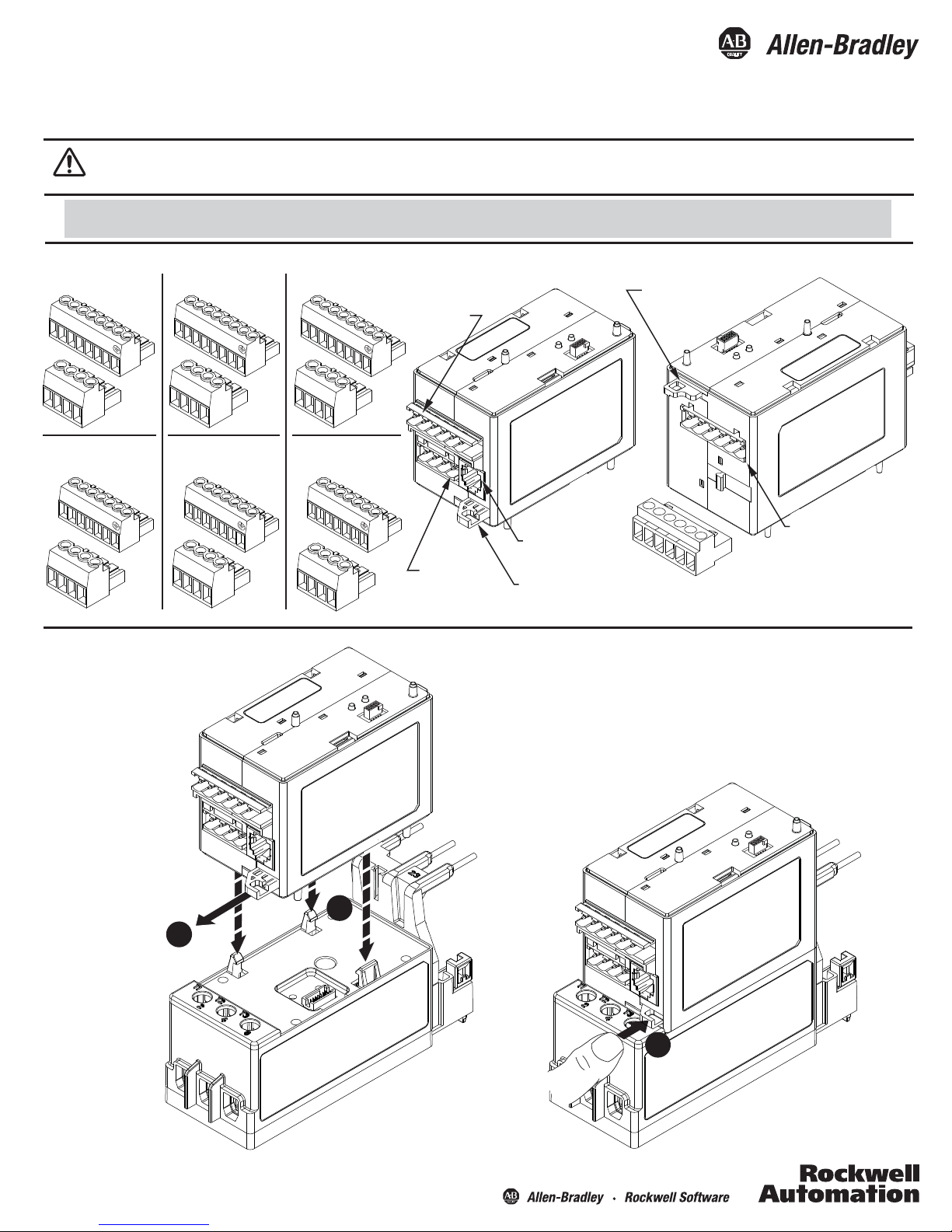
Features
193-EIO-22-24D
A
1
A1
A2
193-EIO-63- _ _ _
A1
A1
A2
IN2
IN3
IN4
IN5
193-EIOGP-42- _ _ _
A1
A1
A2
IN2
IN3
IT1
IT2
Power / PTC
Terminals
Communication
Module Latch
R13
R14
193-EIO-22-120 and
193-EIO-22-240
A1
A1
A2
R13
R14
Installation
R13
R14
R23
R24
193-EIO-43- _ _ _
A1
A1
A2
IN2
IN3
R13
R14
R23
R24
R13
R14
S1
S2
193-EIOGP-22- _ _ _
A1
A1
A2
IT1
IT2
R13
R14
S1
S2
Relay / Ground
Fault Terminals
Expansion Bus
Connector
Sensing Module
Latch
IN1
IN0
A2
R04
R03
A1
Input / Output
Terminals
IMPORTANT - Tightening screws
while the 6 position connector is
plugged in could result in damage
to the connector.
1
2
3
Page 2
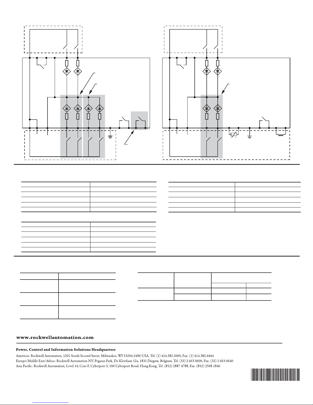
Wiring Diagrams
193-EIOGP-_ _-_ _ _193-EIO-_ _-_ _ _
R03
A1
R04
RELAY 0
A2
A1A1
(+)
IN0
A2
(-)
IN2
IN1
IN3
Additional Inputs for 193-EIO-43-_ _ _
and 193-EIO-63-24D
Additional Inputs for 193-EIO-63-24D
IN5
PE
IN4
R14R13
Additional Outputs for
193-EIO-43-_ _ _ and
193-EIO-63-24D
Power Requirements
193-EIO-22-24D, 193-EIO-63-24D, 193-EIOGP-42-24D
Nominal Supply Voltage (Us)
Operating Range 11 - 30V DC
Rated Supply Current 725mA @ 11V DC derated to 267mA @ 30V DC
Maximum Surge Current at Power-Up 6A for 1.25ms
Maximum Power Consumption
Maximum Power Interruption Time @ 25 V DC 10ms at all environmental conditions
193-EIO-22-120, 193-EIO-43-120, 193-EIOGP-22-120
Rated Supply Voltage (Us) 120V AC
Operating Range 85 - 132V AC
Rated Supply Current 118mA @ 85V AC derated to 65mA @ 132V AC
Maximum Surge Current at Power-Up 5.2A for 1.00ms
Maximum Power Consumption
Maximum Power Interruption Time @ 120V AC 10ms at all environmental conditions
24V DC
6W
6W
R03
A1
R04
RELAY 0
RELAY 2RELAY 1
R24R23
A2
A1A1
(+)
IN0
A2
(-)
IN2
IN1
IN3
Additional Inputs for 193-EIOGP-42-24D
RELAY 1
PTC
IT1
PE
IT2
+
t
R14R13
Ground
Fault
S2S1
193-EIO-22-240, 193-EIO-43-240, 193-EIOGP-22-240
Rated Supply Voltage (Us) 240V AC
Operating Range 184 - 265V AC
Rated Supply Current 58mA @ 172V AC derated to 33mA @ 310V AC
Maximum Surge Current at Power-Up 5.8A for 1.25ms
Maximum Power Consumption 6W
Maximum Po wer Interruption Time @ 240V AC
10ms at all environmental conditions
Input / Output Ratings
Inputs
Cat No
193-EIO-22-24D
193-EIO-63-24D
193-EIOGP-42-24D
193-EIO-22-120
193-EIO-43-120
193-EIOGP-22-120
193-EIO-22-240
193-EIO-43-240
193-EIOGP-22-240
Allen-Bradley, Rockwell Software, and Rockwell Automation are trademarks of Rockwell Automation, Inc.
Trademarks not belonging to Rockwell Automation are property of their respective companies.
Publication 193-IN058D-EN-P - June 2016
Operating Voltage Range
11 - 30V DC
74 - 132V AC
159 - 265V AC
Cat No
ALL
Rated Operating
Current (Ie)
5A @ 250V AC
0.25A @ 220V DC
Outputs
Output Current
Rating
Resistive (P.F. = 1.0) Inductive
5A @ 250V AC
5A @ 5-30V DC
Copyright © 2016 Rockwell Automation, Inc. All Rights Reserved. Printed in USA.
2A @ 250V AC
2A @ 5-30V DC
DIR 10000518534 (Version 03)
PN-356926
 Loading...