

Allen-Bradley 1790D-T0B16, 1790D-T8BV8V, 1790D-T8BV8B, 1790D-T0V16, 1790D-T0W6 Installation Instructions Manual
...Page 1

Installation Instructions
DeviceNet Digital Base Terminal
Block CompactBlock LDX I/O
Catalog Numbers 1790D-T16BV0, 1790D-T8BV8V,
1790D-T8BV8B, 1790D-T0B16, 1790D-T0V16, 1790D-T0W6,
1790D-T8A0, 1790D-T0A6
Table of Contents
Topic Page
Important User Information 2
Environment and Enclosure 3
Prevent Electrostatic Discharge 3
North American Hazardous Location Approval 5
Before You Begin 5
Install the Base Block 6
Set the Node Address on the Base Block 6
Mount the Optional Expansion Block 9
Wiring the Terminal Block 10
Interpret the Status Indicators 15
Cable Break Procedures 16
Specifications 17
Page 2
2 DeviceNet Digital Base Terminal Block CompactBlock LDX I/O
Important User Information
Solid-state equipment has operational characteristics differing from those of electromechanical
equipment. Safety Guidelines for the Application, Installation and Maintenance of Solid State Controls
(Publication SGI-1.1
http://www.rockwellautomation.com/literature/
solid-state equipment and hard-wired electromechanical devices. Because of this difference, and also
because of the wide variety of uses for solid-state equipment, all persons responsible for applying this
equipment must satisfy themselves that each intended application of this equipment is acceptable.
In no event will Rockwell Automation, Inc. be responsible or liable for indirect or consequential damages
resulting from the use or application of this equipment.
The examples and diagrams in this manual are included solely for illustrative purposes. Because of the
many variables and requirements associated with any particular installation, Rockwell Automation, Inc.
cannot assume responsibility or liability for actual use based on the examples and diagrams.
No patent liability is assumed by Rockwell Automation, Inc. with respect to use of information, circuits,
equipment, or software described in this manual.
available from your local Rockwell Automation sales office or online at
) describes some important differences between
Reproduction of the contents of this manual, in whole or in part, without written permission of Rockwell
Automation, Inc., is prohibited.
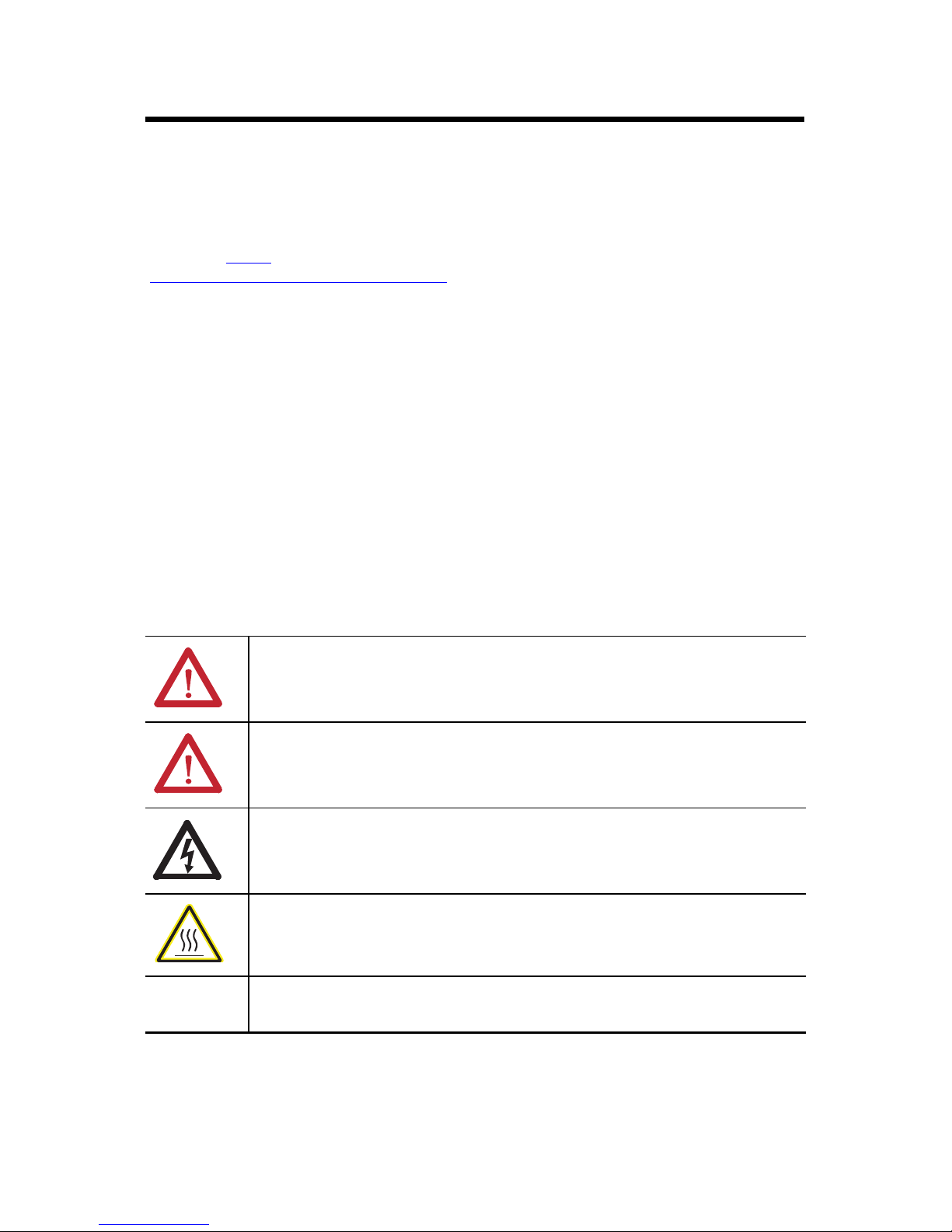
Throughout this manual, when necessary, we use notes to make you aware of safety considerations.
WARNING: Identifies information about practices or circumstances that can cause an
explosion in a hazardous environment, which may lead to personal injury or death,
property damage, or economic loss.
ATTENTION: Identifies information about practices or circumstances that can lead to
personal injury or death, property damage, or economic loss. Attentions help you identify
a hazard, avoid a hazard and recognize the consequences.
SHOCK HAZARD: Labels may be on or inside the equipment (for example, drive or
motor) to alert people that dangerous voltage may be present.
BURN HAZARD: Labels may be on or inside the equipment (for example, drive or motor)
to alert people that surfaces may reach dangerous temperatures.
IMPORTANT Identifies information that is critical for successful application and understanding of
the product.
Publication 1790-IN012C-EN-P - January 2015
Page 3
DeviceNet Digital Base Terminal Block CompactBlock LDX I/O 3
Environment and Enclosure
ATTENTION: This equipment is intended for use in a Pollution Degree 2
industrial environment, in overvoltage Category II applications (as defined in
IEC publication 60664-1), at altitudes up to 2000 meters (6562 ft)
without derating.
This equipment is considered Group 1, Class A industrial equipment according
to IEC/CISPR Publication 11. Without appropriate precautions, there may be
potential difficulties ensuring electromagnetic compatibility in other
environments due to conducted as well as radiated disturbance.
This equipment is supplied as open-type equipment. It must be mounted within
an enclosure that is suitably designed for those specific environmental
conditions that will be present and appropriately designed to prevent personal
injury resulting from accessibility to live parts. The enclosure must have
suitable flame-retardant properties to prevent or minimize the spread of flame,
complying with a flame spread rating of 5VA, V2, V1, V0 (or equivalent) if
non-metallic. The interior of the enclosure must be accessible only by the use
of a tool. Subsequent sections of this publication may contain additional
information regarding specific enclosure type ratings that are required to
comply with certain product safety certifications.
In addition to this publication, see:
• Industrial Automation Wiring and Grounding Guidelines, for additional
installation requirements, Allen-Bradley publication 1770-4.1
• NEMA Standards publication 250 and IEC publication 60529, as
applicable, for explanations of the degrees of protection provided by
different types of enclosure.
Prevent Electrostatic Discharge
ATTENTION: This equipment is sensitive to electrostatic discharge, which can
cause internal damage and affect normal operation. Follow these guidelines
when you handle this equipment:
• Touch a grounded object to discharge potential static.
• Wear an approved grounding wriststrap.
• Do not touch connectors or pins on component boards.
• Do not touch circuit components inside the equipment.
• Use a static-safe workstation, if available.
• Store the equipment in appropriate static-safe packaging when not in use.
.
Publication 1790-IN012C-EN-P - January 2015
Page 4
4 DeviceNet Digital Base Terminal Block CompactBlock LDX I/O
WARNING: If you connect or disconnect the communications cable with
power applied to this module or any device on the network, an electrical arc
can occur. This could cause an explosion in hazardous location installations.
Be sure that power is removed or the area is nonhazardous before
proceeding.
WARNING: If you connect or disconnect wiring while the field-side power is
on, an electrical arc can occur. This could cause an explosion in hazardous
location installations.
Be sure that power is removed or the area is nonhazardous before
proceeding.
ATTENTION: To comply with the CE Low Voltage Directive (LVD), all wiring
connections to this equipment must be powered from a source compliant with
the following:
Safety Extra Low Voltage (SELV) or Protected Extra Low Voltage (PELV).
ATTENTION: To comply with UL restrictions, DeviceNet must be powered
from a source compliant with the following:
Class 2 or Limited Voltage/Current.
Publication 1790-IN012C-EN-P - January 2015
Page 5
DeviceNet Digital Base Terminal Block CompactBlock LDX I/O 5
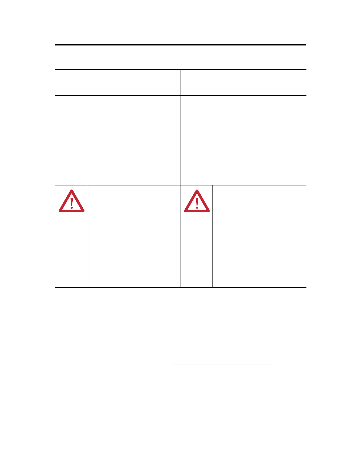
North American Hazardous Location Approval
The following information applies when
operating this equipment in hazardous
locations:
Products marked "CL I, DIV 2, GP A, B, C, D" are suitable for
use in Class I Division 2 Groups A, B, C, D, Hazardous
Locations and nonhazardous locations only. Each product is
supplied with markings on the rating nameplate indicating
the hazardous location temperature code. When combining
products within a system, the most adverse temperature
code (lowest "T" number) may be used to help determine the
overall temperature code of the system. Combinations of
equipment in your system are subject to investigation by the
local Authority Having Jurisdiction at the time of
installation.
EXPLOSION HAZARD
• Do not disconnect equipment unless
power has been removed or the area is
known to be nonhazardous.
• Do not disconnect connections to this
equipment unless power has been
removed or the area is known to be
nonhazardous. Secure any external
connections that mate to this equipment
by using screws, sliding latches, threaded
connectors, or other means provided with
this product.
• Substitution of components may impair
suitability for Class I, Division 2.
• If this product contains batteries, they
must only be changed in an area known to
be nonhazardous.
Informations sur l’utilisation de cet
équipement en environnements dangereux:
Les produits marqués "CL I, DIV 2, GP A, B, C, D" ne
conviennent qu'à une utilisation en environnements de
Classe I Division 2 Groupes A, B, C, D dangereux et non
dangereux. Chaque produit est livré avec des marquages sur
sa plaque d'identification qui indiquent le code de
température pour les environnements dangereux. Lorsque
plusieurs produits sont combinés dans un système, le code
de température le plus défavorable (code de température le
plus faible) peut être utilisé pour déterminer le code de
température global du système. Les combinaisons
d'équipements dans le système sont sujettes à inspection
par les autorités locales qualifiées au moment de
l'installation.
RISQUE D’EXPLOSION
• Couper le courant ou s'assurer que
l'environnement est classé non dangereux
avant de débrancher l'équipement.
• Couper le courant ou s'assurer que
l'environnement est classé non dangereux
avant de débrancher les connecteurs.
Fixer tous les connecteurs externes reliés
à cet équipement à l'aide de vis, loquets
coulissants, connecteurs filetés ou autres
moyens fournis avec ce produit.
• La substitution de composants peut rendre
cet équipement inadapté à une utilisation
en environnement de Classe I, Division 2.
• S'assurer que l'environnement est classé
non dangereux avant de changer les piles.
Before You Begin
Read this section about important CompactBlock I/O requirements.
Current functions of CompactBlock LDX I/O blocks require the current, modular
electronic data sheet (EDS) file for RSNetWorx for DeviceNet software, version 8.0 or
later. These files are are available online at http://www.ab.com/networks/eds/
EDS files for blocks with matching catalog numbers for both D-shell and terminal block
versions are the same. On the website and in RSNetWorx for DeviceNet software,ind the
EDS file for both versions of the blocks. For example, for the EDS file for 1790D-T8BV8B
blocks, use the EDS file labelled 1790D-8BV8B.
.
Publication 1790-IN012C-EN-P - January 2015
Page 6
6 DeviceNet Digital Base Terminal Block CompactBlock LDX I/O
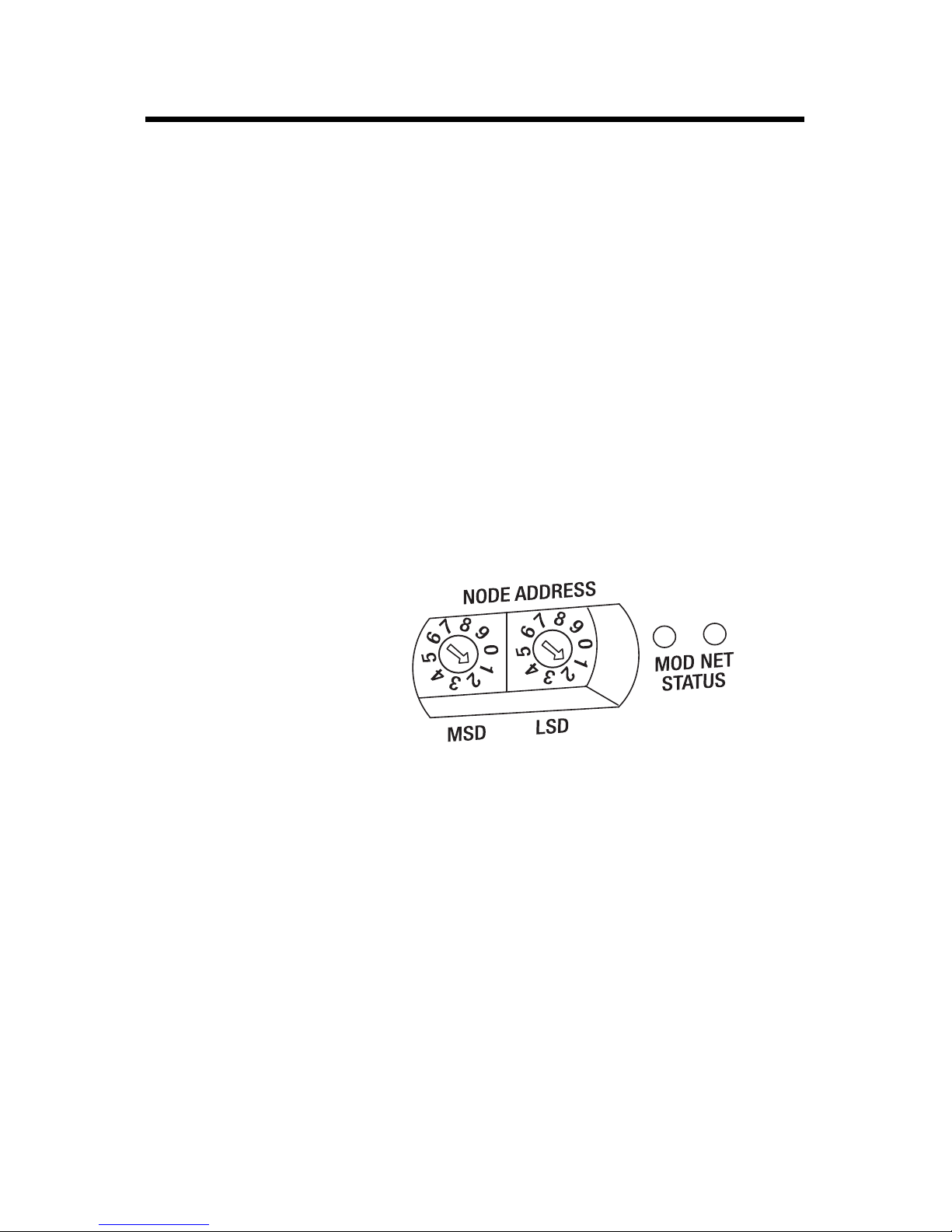
Example: Node
Address is set at 11
Install the Base Block
To install the base block:
• set the node address on the base block.
• mount the base block.
• mount the optional expansion blocks.
• wire the terminal block.
• connect the DeviceNet cable.
Set the Node Address on the Base Block
When setting the node address on the base block, note that each base block comes with its
internal program set for node address 63. To reset the node address, adjust the switches on
the front of the base block. The two switches are most significant digit (MSD) and least
significant digit (LSD). You can set switches to 00...63.
Node Address Example
The base block reads the rotary switches at power up only. Switch settings between 64 and
99 cause the block to use the last valid node address stored internally.
You can also set the node address through RSNetWorx for DeviceNet software or a similar
configuration tool.
When you use software configuration for the node address, set the switches to 64…99.
Publication 1790-IN012C-EN-P - January 2015
Page 7
DeviceNet Digital Base Terminal Block CompactBlock LDX I/O 7
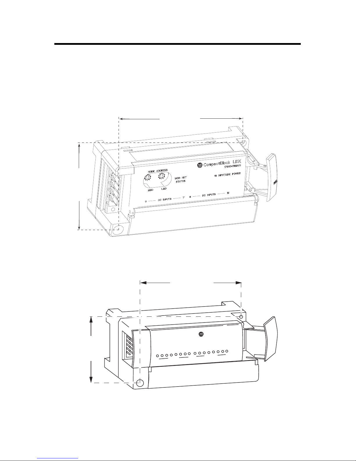
16-point Expansion Module
Expansion
Cable
Cover
16-point Base Module
95 mm
(3.74 in.)
41 mm
(1.6 in.)
95 mm
(3.74 in.)
41 mm
(1.6 in.)
Expansion
Cable
Cover
44251
44252
Mount the Base Module
Mount the base block to a panel or DIN rail. We recommend that you
ground the panel or DIN rail before mounting the block.
Dimensions
EXPANSION UNIT
0
DC INPUTS
CompactBlock LDX
DC INPUTS
8
7
1790-16BVOX
16 INPUTS-DCPOWER
15
Publication 1790-IN012C-EN-P - January 2015
Page 8
8 DeviceNet Digital Base Terminal Block CompactBlock LDX I/O
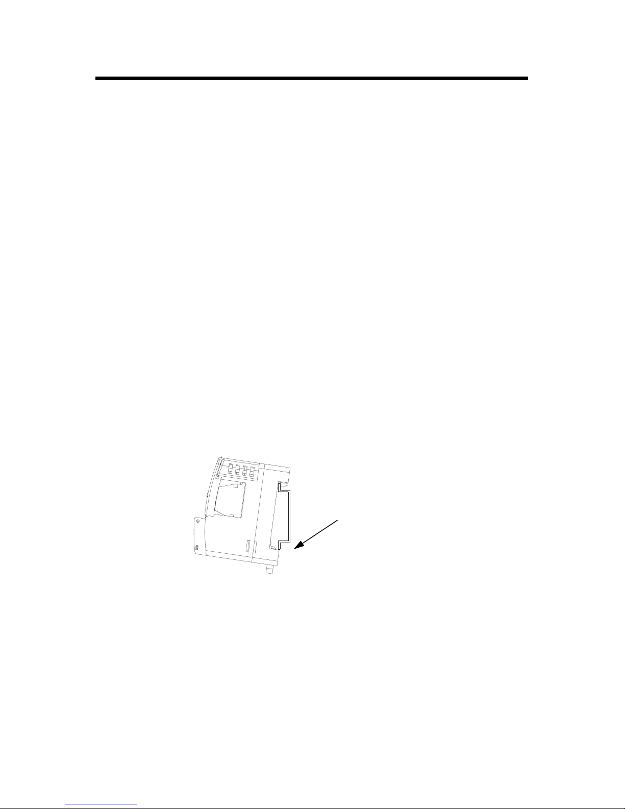
44253
Locking Lever
Mount on a Panel
For panel mounting, use these steps.
1. Place the block against the panel where you want it mounted.
2. Gently pull and position the expansion cover to the left.
3. Place a center punch, nail, or similar device through the mounting holes in the
block and make two marks on the panel at the lower-left and upper-right corners
of the module.
4. Remove the block and drill two holes in the panel to accommodate each of the
mounting screws.
5. Replace the block on the panel and place a screw through each of the two
mounting holes.
6. Tighten the screws until the block is firmly in place.
Mount on DIN Rail
For DIN-rail mounting, use these steps.
1. Hook the top slot of the base block over the DIN rail.
2. Pull down on the locking lever while pressing the base block against the rail.
3. Push up on the locking lever to secure the base block to the rail when the base
block is flush against the rail.
Publication 1790-IN012C-EN-P - January 2015
Page 9

DeviceNet Digital Base Terminal Block CompactBlock LDX I/O 9
44372
Right Side Up
Right Side Up Right Side Up Right Side Up
44373
The longer expansion cable, catalog
number 1790-15CMCBL, provides for up
to 7 cm (2.76 in.) of space between
blocks.
Right Side Up
Upside Down
Right Side Up
Mount the Optional Expansion Block
To mount the optional expansion block, use these steps.
1. Mount the expansion block by connecting it to a previously-installed
CompactBlock LDX I/O base or expansion block.
2. Beginning with the base block, mount your expansion block either horizontally
or vertically.
• To mount horizontally (left to right), add an expansion block in an
end-to-end configuration.
• To mount vertically (up or down), add an expansion block either up or down
in a back-to-back configuration. In this configuration, you must use the
optional 15 cm (5.9 in.) ribbon cable, catalog number 1790-15CMCBL, and
alternately position the block in a right-side up, upside-down fashion.
3. Mount your block on a panel or DIN rail.
Publication 1790-IN012C-EN-P - January 2015
Page 10

10 DeviceNet Digital Base Terminal Block CompactBlock LDX I/O
Wiring the Terminal Block
WARNING: If you connect or disconnect wiring while the field-side power is
on, an electrical arc can occur. This could cause an explosion in hazardous
location installations. Be sure that power is removed or the area is
nonhazardous before proceeding.
See the diagrams that follow for wiring information.
1790D-T16BVO Input Base Block Wiring Diagram
IN0
IN2 IN4 IN6 COM0 COM1 IN8 IN10 IN12 IN14
IN1
IN3 IN5 IN7 COM0 COM1 IN9 IN11 IN13 IN15
44262
• For inputs 0…7: For sinking inputs, wire COM 0 to Field Power (-) GND.
For sourcing inputs, wire COM 0 to Field Power (+) 24V DC.
• For inputs 8…15: For sinking inputs, wire COM 1 to Field Power (-) GND.
For sourcing inputs, wire COM 1to Field Power (+) 24V DC.
Note that both COM 0 and COM 1 are internally connected.
Publication 1790-IN012C-EN-P - January 2015
Page 11

DeviceNet Digital Base Terminal Block CompactBlock LDX I/O 11
IN0
IN1
IN3 IN5 IN7 COM GND OUT1 OUT3 OUT5 OUT7
IN2 IN4 IN6 COM VDC OUT0 OUT2 OUT4 OUT6
44263
1790D-T8BV8V Input/Output Base Block Wiring Diagram
• For sinking inputs, wire COM to Field Power (-) GND.
For sourcing inputs, wire COM to Field Power (+) 24V DC.
Note that both COM are internally connected.
• For sinking outputs, wire V DC to Field Power (+) 24V DC, and wire GND to
Field Power (-) GND.
1790D-T8BV8B Input/Output Base Block Wiring Diagram
IN0
IN2 IN4 IN6 COM VDC OUT0 OUT2 OUT4 OUT6
IN1
IN3 IN5 IN7 COM GND OUT1 OUT3 OUT5 OUT7
• For sinking inputs, wire COM to Field Power (-) GND.
For sourcing inputs, wire COM to Field Power (+) 24V DC.
Note that COM are internally connected.
• For sourcing outputs, wire V DC to Field Power (+) 24V DC, and
wire GND to Field Power (-) GND.
44264
Publication 1790-IN012C-EN-P - January 2015
Page 12

12 DeviceNet Digital Base Terminal Block CompactBlock LDX I/O
OUT0
OUT1
OUT3 OUT5 OUT7 GND0 GND1 OUT9 OUT11 OUT13 OUT15
OUT2 OUT4 OUT6 VDC0 VDC1 OUT8 OUT10 OUT12 OUT14
44265
OUT0
OUT1
OUT3 OUT5 OUT7 GND0 GND1 OUT9 OUT11 OUT13 OUT15
OUT2 OUT4 OUT6 VDC0 VDC1 OUT8 OUT10 OUT12 OUT14
44182
1790D-T0B16 Output Base Block Wiring Diagram
• For sourcing outputs, wire V DC 0 and V DC 1 to Field Power (+) 24V DC, and
wire GND0 and GND1 to Field Power (-) GND.
1790D-TOV16 Output Base Block Wiring Diagram
• For sinking outputs, wire V DC 0 (pin 9) and V DC 1 (pin 11) to Field Power
(+) 24V DC, and wire GND0 (pin 10) and GND1 (pin 12) to Field Power (-)
GND.
Publication 1790-IN012C-EN-P - January 2015
Page 13

DeviceNet Digital Base Terminal Block CompactBlock LDX I/O 13
1790D-T0W6 Relay Output Base Block Wiring Diagram
VDC
NC OUT0 OUT1 OUT2 OUT3 OUT4 OUT5 NC NC
GND
NC COM0 COM1 COM2 COM3 COM4 COM5 NC NC
• Wire V DC to Field Power (+) 24V DC.
Wire GND to Field Power (-) GND.
1790D-T8A0 AC Input Base Block Wiring Diagram
VAC
VAC IN0 IN1 IN2 IN3 IN4 IN5 IN6 IN7
COM
COM COM COM COM COM COM COM COM COM
• Wire 120V AC Field Power to V AC and COM.
Note that all V AC are internally connected. All COM are internally connected.
44266
44267
1790D-T0A6 AC Output Base Block Wiring Diagram
VAC
VAC OUT0 OUT1 OUT2 OUT3 OUT4 OUT5 NC NC
COM
COM COM COM COM COM COM COM NC NC
• Wire 120V AC Field Power to V AC and COM.
Note that all V AC are internally connected. All COM are internally connected.
44268
Publication 1790-IN012C-EN-P - January 2015
Page 14

14 DeviceNet Digital Base Terminal Block CompactBlock LDX I/O
Wiring Diagram for
1799-DNETCON
Connector
Wiring Diagram for
1799-DNC5MMS
Connector
V+ Red
V- Black
Drain/Shield
Can_H White
Can_L Blue
V+ Red
Can_H White
Drain/Shield
Can_L Blue
V- Black
44164
Connect the DeviceNet Cable
Follow these procedures to connect the DeviceNet cable to the base block. The DeviceNet
connector is not supplied with the base block. You must purchase the connector separately.
These are the types of connectors you order directly from Rockwell Automation.
• 1799-DNETCON – 5-position open-style connector
• 1799-DNETSCON – 5-position open-style connector with locking screws
• 1799-DNC5MMS – 5-position open-style to 12 mm (0.47 in.) connector with
locking screws
WARNING: If you connect or disconnect the communication cable with
power applied to this module or any device on the network, an electrical arc
can occur. This could cause an explosion in hazardous location installations.
Be sure that power is removed or the area is nonhazardous before
proceeding
1. Connect the DeviceNet wiring (drop line) to one of the DeviceNet connectors as
shown in the figure, noting that a color-coded wiring diagram is printed next to
the connector on the left side of the base block.
1. Attach the connector to the base block once you have properly wired
the drop line to the connector.
2. Use the locking screws on the connector to fasten it to the base block,
Publication 1790-IN012C-EN-P - January 2015
if applicable.
Page 15

DeviceNet Digital Base Terminal Block CompactBlock LDX I/O 15
Interpret the Status Indicators
Read this section for information about how to interpret base block status indicators. The
base block has these status indicators:
•Block status
•Network status
•I/O status
If a module status indicator is flashing red, refer to the cable break procedures section.
Status Indicators
Indicator Status Description
Module Solid red Unrecoverable fault in base unit.
Replace base block.
Flashing red Fault in expansion unit, or
Node address switches do not match current node
address.
Reconnect or replace, as needed.
Solid green Normal operation.
Off No power.
Apply power to device.
Network Solid red Module node number is a duplicate of an existing
node, or network communication issues exist.
Change module node number to an unused address, or
verify network wiring is correct and communication is
stable.
Flashing red An I/O connection has timed out.
Solid green The module is operating in a normal condition, and the
Cycle power to the module.
module is online with connections in the established
state. As a group 2 module, the module is allocated to
a master.
Publication 1790-IN012C-EN-P - January 2015
Page 16

16 DeviceNet Digital Base Terminal Block CompactBlock LDX I/O
Status Indicators
Indicator Status Description
Network Flashing green The module is online with no connections in the
established state.
Establish connections to other nodes. As a group 2
module, allocate the module to a master.
Off No power.
Wait until the module has completed the dup_MAC_id
test or power the module.
I/O Status Indicators
Indicator Status Description
Each output None Output is not energized.
Green Output is energized.
Each input None No valid input is present.
Green Valid input is present.
Cable Break Procedures
A cable break in any location between either of the following produces data of 0 in the data
table for all inputs down stream of the cable break:
• Base and digital input expansion module
• Digital input expansion module and another digital input expansion module
All digital-expansion inputs produce data of 0 if the expansion cable is removed. No status
is in the default produced assembly. Attribute 101 in the identity object reports module
faults.
If no faults are present, an explicit message GET command returns 0.
If the ribbon cable is disconnected, it returns 0x04, which is for module location change.
The module status indicator also flashes indicating a fault if an expansion is disconnected.
Select an alternate produced assembly that contains the expansion status byte, using the
EDS Properties configuration dialog.
Publication 1790-IN012C-EN-P - January 2015
Page 17

DeviceNet Digital Base Terminal Block CompactBlock LDX I/O 17
Specifications
Universal DC Input Base Block - 1790D-T16BV0
Attribute Value
Number of inputs 16
Input type Sink, source 24V DC
Voltage, off-state input, max 5V DC
Voltage, on-state input, max 28.8V DC
Voltage, on-state input, nom 24V DC
Voltage, on-state input, min 9.6V DC
Current, off-state input, max 1.5 mA @ 5V DC
Current, on-state input, max 8 mA @ 28.8V DC per channel
Input impedance, nom 4.8 k
Field power dissipation 3.68 W max @ 28.8V DC
DC field power Supply voltage - 24V DC nom
Voltage range - 10…28.8V DC
1790D-TOV16, 1790D-TOB16
Attribute Value
Number of outputs, nonisolated 16, sinking (1790D-TOV16)
16, sourcing (1790D-TOB16)
Voltage, off-state output, max 28.8V DC
Voltage, on-state output, max 28.8V DC
Voltage, on-state output, nom 24V DC
Voltage, on-state output, min 10V DC
Voltage, on-state drop, max 0.5V DC
Current, on-state output, min 1 mA per channel
Leakage, off-state, max 0.5 mA
Output signal delay, off to on, max 0.5 ms
Output signal delay, on to off, max 1.0 ms
Publication 1790-IN012C-EN-P - January 2015
Page 18

18 DeviceNet Digital Base Terminal Block CompactBlock LDX I/O
1790D-TOV16, 1790D-TOB16
Attribute Value
Output current rating, output, max 0.5 A
Output current rating, common, max 4.0 A
Field power dissipation 2.76 W @ 28.8V DC
DC field power Supply voltage - 24V DC nom
Voltage range - 10…28.8V DC
1790D-T8BV8V, 1790D-T8BV8B
Attribute Value
Number of inputs, non-isolated 8 points , sinking or sourcing
Voltage, off-state input, max 5.0V DC
Voltage, on-state input, max 28.8V DC
Voltage, on-state input, nom 24V DC
Voltage, on-state input, min 9.6V DC
Current, on-state, max 8 mA per channel @ 28.8V DC
Current, on-state, min 1 mA per channel
Input impedance, nom 4.8 k
Number of outputs, non-isolated 8 points, sinking (1790D-T8BV8V)
8 points, sourcing (1790D-T8BV8B)
Voltage, on-state output, max 28.8V DC
Voltage, on-state output, nom 24V DC
Voltage, on-state output, min 10V DC
Voltage, on-state drop, max 0.5V DC
Output current rating, output, max 0.5 A
Output current rating, common, max 4.0 A
Leakage, off-state, max 0.5 mA
Output signal delay, off to on, max 0.5 ms
Publication 1790-IN012C-EN-P - January 2015
Page 19

DeviceNet Digital Base Terminal Block CompactBlock LDX I/O 19
1790D-T8BV8V, 1790D-T8BV8B
Attribute Value
Output signal delay, on to off, max 1.0 ms
Field power dissipation 3.22 W @ 28.8V DC
DC field power Supply voltage - 24V DC nom
Voltage range - 10…28.8V DC
1790D-TOW6
Attribute Value
Relay type Form A, normally open
Single pole, single throw
Output voltage range (load dependent) 5…28V DC @ 2.0 A resistive
48V DC @ 0.8 A resistive
125V AC @ 2.0 A resistive
250V AC @ 2.0 A resistive
Load, min 100 µA, 100 mV DC per point
On-state voltage drop, max 0.5V @ 2.0 A, resistive load, 24V DC
Initial contact resistance 30 milliohms
Expected contact life 300 kcycles resistive
100 kcycles inductive
Off-state leakage, max 1.5 mA
Output delay time, on to off, max 10 ms
Output delay time, off to on, max 10 ms
Relay coil power dissipation 1.7 W @ 28.8V DC
DC relay coil power Supply voltage - 24V DC nom
Voltage range - 19.2…28.8V DC
1790D-T8A0
Attribute Value
Number of inputs, non-isolated 8
Voltage, on-state input, max 132V AC
Voltage, on-state input, nom 120V AC
Publication 1790-IN012C-EN-P - January 2015
Page 20

20 DeviceNet Digital Base Terminal Block CompactBlock LDX I/O
1790D-T8A0
Attribute Value
Voltage, on-state input, min 85V AC
Voltage, on-state drop, max 0.5V DC
Current, on-state input, max 9 mA
Current, off-state input, max 45V AC
Input signal delay, off to on, max 10 ms
Input signal delay, on to off, max 30 ms
Input impedance 18 k
Field power dissipation 3VA @ 132V AC
AC field power Supply voltage - 120V AC, 60 Hz
Voltage range - 15…132V AC, 47…60 Hz
1790D-T0A6
Attribute Value
Number of outputs, nonisolated 6
Load voltage range 15…132V AC
Load current, max 0.5 A rms
Load current, min 10 mA rms
Off-state Leakage current, max 1.0 mA rms @ 100V rms 60 Hz
On-state voltage drop, max 1.3V rms @ max load
Operate time, max 1 ms
Release, max 1/2 cycle + 1 ms
Insulation resistance 1,000 MW min (for input-output)
Input signal delay, off to on 10 ms
Input signal delay, on to off, max 30 ms
Field power dissipation 3.9VA @ rated current
AC field power Supply voltage - 120V AC, 60 Hz
Publication 1790-IN012C-EN-P - January 2015
Voltage range - 15…132V AC, 60 Hz
Page 21

DeviceNet Digital Base Terminal Block CompactBlock LDX I/O 21
General Specifications
Attribute Value
DeviceNet power Supply voltage - 24V DC nom
Voltage range - 10…25V DC
DeviceNet power
dissipation
Network length 500 m (1640 ft) max @ 125 Kbps
Network protocol Slave messaging:
Status indicators Module Status - red/green
Number of nodes 64 max - rotary switch-type node address setting
Communication rate 125 Kbps, 250 Kbps, 500 Kbps - auto baud rate selection
Dimensions (HxWxD),
approx.
Weight, approx. 16pt base blocks: 0.1 kg (0.3 lb)
Enclosure type rating Meets IP20
1.2 W max @ 25V DC
100 m (328 ft) max @ 500 Kbps
• Poll command
• Bit Strobe command
• Cyclic command
• COS command
Network Status - red/green
16pt base blocks:
52 x 104 x 42 mm (2.03 x 4.07 x 1.64 in.)
Isolation voltage 120V AC (continuous), Reinforced Insulation
Type tested at 1250 V AC for 60 seconds, I/O to system
No isolation between individual I/O channels
(1790D-T0A6, -T0W6, and T8A0)
50V DC (continuous), Reinforced Insulation
Type tested at 1250 V AC for 60 seconds, I/O to system
No isolation between individual I/O channels
(1790D-T8BV8B, T8BV8V, T16BV0, T0B16, and T0V16 )
Mounting DIN rail or panel
Wire size 0.25... 2.5 mm² (22...14 AWG) solid or stranded copper wire rated at 75 °C
(167 °F ) or greater 1.2 mm (3/64 in.) insulation max
Wiring terminal screw
torque, max
Removable terminal block
screw torque, max
0.6 Nm (5.2 lb-in.)
0.56 Nm (5.0 lb-in.)
Publication 1790-IN012C-EN-P - January 2015
Page 22

22 DeviceNet Digital Base Terminal Block CompactBlock LDX I/O
General Specifications
Attribute Value
Wiring category
Pilot duty rating Not Rated
North American
temperature code
(1)
Use this conductor category information for planning conductor routing as described in Industrial Automation Wiring
and Grounding Guidelines, publication 1770-4.1.
(1)
2 - on signal ports
2 - on communication ports
T5
Environmental Specifications
Attribute Value
Temperature, operating IEC 60068-2-1 (Test Ad, Operating Cold),
IEC 60068-2-2 (Test Bd, Operating Dry Heat),
IEC 60068-2-14 (Test Nb, Operating Thermal Shock):
0…60 °C (32…140 °F)
Temperature, storage IEC 60068-2-1 (Test Ab, Unpackaged Non-operating Cold),
IEC 60068-2-2 (Test Bb, Unpackaged Non-operating Dry Heat),
IEC 60068-2-14 (Test Na, Unpackaged Non-operating Thermal Shock):
-40…85 °C (-40…185 °F)
Relative humidity IEC 60068-2-30 (Test Db, Unpackaged Damp Heat):
5…90% non-condensing
Vibration IEC 60068-2-6 (Test Fc, Operating):
5 g @ 10…500 Hz
Shock, operating IEC 60068-2-27 (Test Ea, Unpackaged Shock):
30 g
Shock, non-operating IEC 60068-2-27 (Test Ea, Unpackaged Shock):
50 g
Emissions CISPR 11:
Group 1, Class A
ESD immunity IEC 61000-4-2:
8 kV air discharges
Radiated RF immunity IEC 61000-4-3:
10V/m with 1 kHz sine-wave 80%AM from 80…1000 MHz
10V/m with 1 kHz sine-wave 80%AM from 1.4…2 GHz
10V/m with 200 Hz 50% Pulse 100%AM at 900 MHz
Publication 1790-IN012C-EN-P - January 2015
Page 23

DeviceNet Digital Base Terminal Block CompactBlock LDX I/O 23
Environmental Specifications
Attribute Value
EFT/B immunity IEC 61000-4-4:
±2 kV at 5 kHz on signal ports
±2 kV at 5 kHz on communications ports
Surge transient
immunity
Conducted RF immunity IEC 61000-4-6:
IEC 61000-4-5:
±1 kV line-line(DM) and ±2 kV line-earth(CM) on signal ports
±2 kV line-earth(CM) on communications ports
10V rms with 1 kHz sine-wave 80%AM from 150 kHz…80 MHz
Certifications
Certification (when
product is marked)
c-UL-us UL Listed Industrial Control Equipment, certified for US and Canada. See
CE European Union 2004/108/EC EMC Directive, compliant with:
Value
(1)
UL File E150833.
UL Listed for Class I, Division 2 Group A,B,C,D Hazardous Locations,
certified for U.S. and Canada. See UL File E195620.
EN 61326-1; Meas./Control/Lab., Industrial Requirements
EN 61000-6-2; Industrial Immunity
EN 61000-6-4; Industrial Emissions
EN 61131-2; Programmable Controllers (Clause 8, Zone A & B)
RCM Australian Radiocommunications Act, compliant with: AS/NZS CISPR11;
ODVA ODVA conformance tested to DeviceNet specifications
(1)
See the Product Certification link at http://www.rockwellautomation.com/products/certification/ for Declaration of
Conformity, Certificates, and other certification details.
European Union 2006/95/EC LVD, compliant with:
EN 61131-2; Programmable Controllers (Clause 11)
(not for 1790D-T8BV8B, T8BV8V, T16BV0, T0B16, and T0V16)
Industrial Emissions
Publication 1790-IN012C-EN-P - January 2015
Page 24

Rockwell Automation Support
Rockwell Automation provides technical information on the Web to assist you in using its products. At
http://www.rockwellautomation.com/support/
technical and application notes, sample code and links to software service packs, and a MySupport feature
that you can customize to make the best use of these tools.
For an additional level of technical phone support for installation, configuration and troubleshooting, we
offer TechConnect support programs. For more information, contact your local distributor or Rockwell
Automation representative, or visit http://www.rockwellautomation.com/support/
, you can find technical manuals, a knowledge base of FAQs,
.
Installation Assistance
If you experience a problem within the first 24 hours of installation, please review the information that's
contained in this manual. You can also contact a special Customer Support number for initial help in getting
your product up and running.
United States or Canada 1.440.646.3434
Outside United States or
Canada
Use the Worldwide Locator
http://www.rockwellautomation.com/support/americas/phone_en.html
contact your local Rockwell Automation representative.
at
, or
New Product Satisfaction Return
Rockwell Automation tests all of its products to ensure that they are fully operational when shipped from
the manufacturing facility. However, if your product is not functioning and needs to be returned, follow
these procedures.
United States Contact your distributor. You must provide a Customer Support case number
(call the phone number above to obtain one) to your distributor to complete the
return process.
Outside United States Please contact your local Rockwell Automation representative for the return
procedure.
Documentation Feedback
Your comments will help us serve your documentation needs better. If you have any suggestions on how to
improve this document, complete this form, publication RA-DU002
http://www.rockwellautomation.com/literature/
Allen-Bradley, Rockwell Automation, CompactBlock LDX and RSNetWorx for DeviceNet, are trademarks of Rockwell Automation, Inc.
DeviceNet is a trademark of Open DeviceNet Vendor Association.
.
, available at
Trademarks not belonging to Rockwell Automation are property of their respective companies.
Publication 1790-IN012C-EN-P - January 2015 PN-297576
Supersedes Publication 1790-IN012B-EN-P - July 2008 Copyright © 2015 Rockwell Automation, Inc. All rights reserved. Printed in Korea.
 Loading...