

Page 1
Enhanced and
Ethernet PLC-5
Programmable
Controllers
1785-L11B, -L20B, -L30B, -L40B,
-L40L, -L60B, -L60L, -L80B, -L20E,
-L40E, -L80E, -L26B, -L46B, -L86B
User Manual
Page 2

Important User Information
Solid state equipment has operational characteristics differing from those of
electromechanical equipment. Safety Guidelines for the Application,
Installation and Maintenance of Solid State Controls (Publication SGI-1.1
available from your local Rockwell Automation sales office or online at
http://www.ab.com/manuals/gi) describes some important differences
between solid state equipment and hard-wired electromechanical devices.
Because of this difference, and also because of the wide variety of uses for
solid state equipment, all persons responsible for applying this equipment
must satisfy themselves that each intended application of this equipment is
acceptable.
In no event will Rockwell Automation, Inc. be responsible or liable for
indirect or consequential damages resulting from the use or application of
this equipment.
The examples and diagrams in this manual are included solely for illustrative
purposes. Because of the many variables and requirements associated with
any particular installation, Rockwell Automation, Inc. cannot assume
responsibility or liability for actual use based on the examples and diagrams.
No patent liability is assumed by Rockwell Automation, Inc. with respect to
use of information, circuits, equipment, or software described in this manual.
Reproduction of the contents of this manua l , in whole or in part, without
written permission of Rockwell Automation, Inc. is prohibited.
Throughout this manual, when necessary we use notes to make you aware of
safety considerations.
WARNING
IMPORTANT
ATTENTION
SHOCK HAZARD
BURN HAZARD
Identifies information about practices or circumstances
that can cause an explosion in a hazardous environment,
which may lead to personal injur y or death, property
damage, or economic loss.
Identifies information that is critical for successful
application and understanding of the product.
Identifies information about practices or circumstances
that can lead to personal injury or death, property
damage, or economic loss. Attentions help you:
• identify a hazard
• avoid a hazard
• recognize the consequence
Labels may be located on or inside the equipment (e.g.,
drive or motor) to alert people that dangerous voltage may
be present.
Labels may be located on or inside the equipment (e.g.,
drive or motor) to alert people that surfa ces may be
dangerous temperatures.
Page 3

Summary of Changes
Summary of Changes
Changes to this Manual
Find the New Information
This user manual contains new and updated information.
The black revision bars, as shown on the left, indicate the changes.
For specific locations of the new information, refer to the table below.
This New and Updated Information Is on Page
Domain Name Service 11-15
User Provided Web Pages 11-16
Multihop Messaging over Ethernet 11-29
TCP/IP Communications 11-32
Additional Ethernet Diagnostics 11-35
Memory Card Diagnostics B-12
Troubleshooting and Diagnostics F-2
Additional Ethernet PLC-5 Controller Enhan ce ment
Ethernet PLC-5 controllers support use of the 1785-RC Relay Cartridge.
The relay cartridge serves as an interface from the controller to a user-supplied
external device such as an Allen-Bradley 700P relay. When the controller is in
run mode, it monitors online ladder program edits and I/O forcing activity.
When either of these is detected, the controller opens the relay on the relay
cartridge for one second.
1 Publication 1785-UM012D - EN-P - July 2005
Page 4

Summary of Changes 2
Notes
Publication 1785-UM012D-EN-P - July 2005
Page 5

Table of Contents
Preface
Understanding Your
Programmable Controller
Purpose of This Manual. . . . . . . . . . . . . . . . . . . . . . . . . . . . . . . . . . . . P-1
Related PLC-5 Documentation. . . . . . . . . . . . . . . . . . . . . . . . . . . . . . P-1
Terms Used in This Manual. . . . . . . . . . . . . . . . . . . . . . . . . . . . . . . . . P-2
Manual Overview. . . . . . . . . . . . . . . . . . . . . . . . . . . . . . . . . . . . . . . . . P-3
Chapter 1
Using This Chapter . . . . . . . . . . . . . . . . . . . . . . . . . . . . . . . . . . . . . . . 1-1
Lay Out the System . . . . . . . . . . . . . . . . . . . . . . . . . . . . . . . . . . . . . . . 1-1
Identifying Controller Components . . . . . . . . . . . . . . . . . . . . . . . . . . 1-2
PLC-5/11, -5/20, and -5/26 Controller Front Panels. . . . . . . . . 1-3
PLC-5/40, -5/46, -5/60, -5/80, and -5/86
Controller Front Panel. . . . . . . . . . . . . . . . . . . . . . . . . . . . . . . . . . 1-5
PLC-5/20E Controller Front Panel . . . . . . . . . . . . . . . . . . . . . . 1-6
PLC-5/40E and -5/80E Controller Front Panels . . . . . . . . . . . 1-7
PLC-5/40L and -5/60L Controller Front Panels . . . . . . . . . . . 1-8
Programming Features. . . . . . . . . . . . . . . . . . . . . . . . . . . . . . . . . . . . 1-10
Using a Controller Channel as a Remote I/O Scanner . . . . . . . . . . 1-11
Using a Controller Channel as a Remote I/O Adapter . . . . . . . . . . 1-12
Using a PLC-5/40L, -5/60L Programmable Controller as an
Extended-Local I/O Scanner . . . . . . . . . . . . . . . . . . . . . . . . . . . . . . 1-14
Selecting and Placing I/ O
Placing Syste m Hardware
Chapter 2
Using This Chapter . . . . . . . . . . . . . . . . . . . . . . . . . . . . . . . . . . . . . . . 2-1
Selecting I/O Modules. . . . . . . . . . . . . . . . . . . . . . . . . . . . . . . . . . . . . 2-1
Guidelines for Selecting I/O Modules . . . . . . . . . . . . . . . . . . . . 2-2
Selecting I/O Module Density . . . . . . . . . . . . . . . . . . . . . . . . . . . . . . 2-2
Placing I/O Modules in a Chassis. . . . . . . . . . . . . . . . . . . . . . . . . . . . 2-3
Chapter 3
Using This Chapter . . . . . . . . . . . . . . . . . . . . . . . . . . . . . . . . . . . . . . . 3-1
Determining the Proper Environment . . . . . . . . . . . . . . . . . . . . . . . . 3-1
Protecting Your Controller . . . . . . . . . . . . . . . . . . . . . . . . . . . . . . . . . 3-3
Preventing Electrostatic Discharge. . . . . . . . . . . . . . . . . . . . . . . . . . . 3-3
Laying Out Your Cable Raceway. . . . . . . . . . . . . . . . . . . . . . . . . . . . . 3-4
Categorize Conductors . . . . . . . . . . . . . . . . . . . . . . . . . . . . . . . . 3-4
Route Conductors . . . . . . . . . . . . . . . . . . . . . . . . . . . . . . . . . . . 3-4
Laying Out Your Backpanel Spacing . . . . . . . . . . . . . . . . . . . . . . . . . 3-5
Chassis Dimensions (Series B) . . . . . . . . . . . . . . . . . . . . . . . . . . . 3-5
I/O Chassis and External Power Supply Dimensions . . . . . . . 3-6
Grounding Your System . . . . . . . . . . . . . . . . . . . . . . . . . . . . . . . . . . . 3-6
1 Publication 1785-UM012D - EN-P - July 2005
Page 6

T able of Contents 2
Addressing I/ O and Controller
Memory
Chapter 4
Using This Chapter . . . . . . . . . . . . . . . . . . . . . . . . . . . . . . . . . . . . . . . 4-1
I/O Addressing Concept. . . . . . . . . . . . . . . . . . . . . . . . . . . . . . . . . . . 4-1
Choosing an Addressing Mode . . . . . . . . . . . . . . . . . . . . . . . . . . . . . . 4-3
Addressing Block-Transfer Modules. . . . . . . . . . . . . . . . . . . . . . . . . . 4-7
Addressing Summary . . . . . . . . . . . . . . . . . . . . . . . . . . . . . . . . . . . . . . 4-7
Assigning Racks . . . . . . . . . . . . . . . . . . . . . . . . . . . . . . . . . . . . . . . . . . 4-8
Understanding PLC-5 Controller Memory. . . . . . . . . . . . . . . . . . . . 4-10
Understanding Data Storage (Data-Table Files) . . . . . . . . . . . . 4-11
Addressing File Types . . . . . . . . . . . . . . . . . . . . . . . . . . . . . . . . . 4-13
Understanding Program-File Storage . . . . . . . . . . . . . . . . . . . . . 4-15
Addressing . . . . . . . . . . . . . . . . . . . . . . . . . . . . . . . . . . . . . . . . . . . . . 4-16
Specifying I/O Image Addresses . . . . . . . . . . . . . . . . . . . . . . . . 4-16
Specifying Logical Addresses . . . . . . . . . . . . . . . . . . . . . . . . . . . 4-17
Specifying Indirect Addresses. . . . . . . . . . . . . . . . . . . . . . . . . . . 4-18
Specifying Indexed Addresses. . . . . . . . . . . . . . . . . . . . . . . . . . . 4-20
Specifying Symbolic Addresses. . . . . . . . . . . . . . . . . . . . . . . . . . 4-21
Optimizing Instruction Execution Time
and Controller Memory. . . . . . . . . . . . . . . . . . . . . . . . . . . . . . . . 4-22
Effectively Using I/O Memory. . . . . . . . . . . . . . . . . . . . . . . . . . . . . 4-24
Communicating with
Controller-Resident I/O
Communicating with Remote I/O
Chapter 5
Using This Chapter . . . . . . . . . . . . . . . . . . . . . . . . . . . . . . . . . . . . . . . 5-1
Introduction to PLC-5 Controller Scanning. . . . . . . . . . . . . . . . . . . . 5-1
Program Scanning . . . . . . . . . . . . . . . . . . . . . . . . . . . . . . . . . . . . . . . . 5-2
Transferring Data to Controller-Resident I/O. . . . . . . . . . . . . . . . . . 5-3
Transferring Discrete Data to Controller-Resident I/O . . . . . . . 5-3
Transferring Immediate I/O Requests. . . . . . . . . . . . . . . . . . . . . 5-3
Transferring Block-Transfer Data to Controller-Resident I/O . 5-4
Configuring the System for Controller-Resident I/O . . . . . . . . . . . . 5-4
Chapter 6
Using This Chapter . . . . . . . . . . . . . . . . . . . . . . . . . . . . . . . . . . . . . . . 6-1
Selecting Devices That You Can Connect . . . . . . . . . . . . . . . . . . . . . 6-2
Introduction to Remote I/O. . . . . . . . . . . . . . . . . . . . . . . . . . . . . . . . 6-3
Designing a Remote I/O Link . . . . . . . . . . . . . . . . . . . . . . . . . . . . . . 6-4
Configuring a Controller Channel as a Scanner . . . . . . . . . . . . . . . . . 6-6
Define an I/O Status File . . . . . . . . . . . . . . . . . . . . . . . . . . . . . . . 6-7
Specify Channel Configuration Information . . . . . . . . . . . . . . . . 6-7
Specify the Scan List . . . . . . . . . . . . . . . . . . . . . . . . . . . . . . . . . . . 6-9
Communicating to a Remote I/O Node Adapter . . . . . . . . . . . . . . 6-11
Troubleshooting Remote I/O Communication Difficulties. . . 6-12
Transferring Block Data . . . . . . . . . . . . . . . . . . . . . . . . . . . . . . . . . . 6-13
Block-Transfers of Remote I/O Data . . . . . . . . . . . . . . . . . . . . . . . 6-15
Block-Transfer Sequence with Status Bits . . . . . . . . . . . . . . . . . . . . 6-17
Publication 1785-UM012D-EN-P - July 2005
Page 7

Communicating with a PLC-5
Adapter Channel
Table of Contents 3
Block-Transfer Programming Considerations . . . . . . . . . . . . . . . . . 6-19
General Considerations. . . . . . . . . . . . . . . . . . . . . . . . . . . . . . . . 6-19
For Controller-Resident Local Racks . . . . . . . . . . . . . . . . . . . . . 6-20
Monitoring Remote I/O Scanner Channels. . . . . . . . . . . . . . . . . . . 6-21
Monitoring transmission retries . . . . . . . . . . . . . . . . . . . . . . . . . 6-21
Addressing the I/O Status File . . . . . . . . . . . . . . . . . . . . . . . . . . . . . 6-24
Chapter 7
Using This Chapter . . . . . . . . . . . . . . . . . . . . . . . . . . . . . . . . . . . . . . . 7-1
Configuring Communication to a PLC-5 Adapter Channel . . . . . . . 7-2
Specify an Adapter Channel’s Communication Rate,
Address, and Rack Size . . . . . . . . . . . . . . . . . . . . . . . . . . . . . . . . . 7-3
Specify the Discrete Transfer Configuration Files. . . . . . . . . . . . 7-5
Programming Discrete Transfers in Adapter Mode. . . . . . . . . . . . . 7-10
Programming Block-Transfers of Data to an Adapter Channel . . . 7-10
Configure Block-Transfer Requests . . . . . . . . . . . . . . . . . . . . . . 7-11
Examples of Block-Transfer Ladder Logic
Effects of Programming Block-Transfers to an Adapter-Mode
Controller Channel on Discrete Data Transfer . . . . . . . . . . . . . 7-15
Monitoring the Status of the Adapter Channel . . . . . . . . . . . . . 7-17
Monitoring the Status of the Supervisory Controller. . . . . . . . . 7-18
Monitoring Remote I/O Adapter Channels. . . . . . . . . . . . . . . . . . . 7-19
Communicating with
Extended-Local I/O
Communicating with Devices on a
DH+ Link
Chapter 8
Using This Chapter . . . . . . . . . . . . . . . . . . . . . . . . . . . . . . . . . . . . . . . 8-1
Selecting Devices That You Can Connect . . . . . . . . . . . . . . . . . . . . . 8-1
Cabling . . . . . . . . . . . . . . . . . . . . . . . . . . . . . . . . . . . . . . . . . . . . . . . . . 8-2
Addressing and Placing I/O . . . . . . . . . . . . . . . . . . . . . . . . . . . . . . . . 8-2
Transferring Data. . . . . . . . . . . . . . . . . . . . . . . . . . . . . . . . . . . . . . . . . 8-4
Discrete Data Transfer . . . . . . . . . . . . . . . . . . . . . . . . . . . . . . . . . 8-5
Transferring Block Data . . . . . . . . . . . . . . . . . . . . . . . . . . . . . . . . 8-6
Calculating Block-Transfer Completion Time . . . . . . . . . . . . . . . 8-7
Considerations for Extended-local Racks. . . . . . . . . . . . . . . . . . . 8-8
Configuring the Controller as an Extended-Local I/O Scanner. . . . 8-9
Monitoring Extended-Local I/O Status. . . . . . . . . . . . . . . . . . . . . . 8-12
Chapter 9
Using This Chapter . . . . . . . . . . . . . . . . . . . . . . . . . . . . . . . . . . . . . . . 9-1
Selecting Devices That You Can Connect . . . . . . . . . . . . . . . . . . . . . 9-1
Link Design . . . . . . . . . . . . . . . . . . . . . . . . . . . . . . . . . . . . . . . . . . . . . 9-2
Configuring the Channel for DH+ Communication . . . . . . . . . . . . . 9-3
Using the Global Status Flag File . . . . . . . . . . . . . . . . . . . . . . . . . . . . 9-5
Monitoring DH+ Communication Channels. . . . . . . . . . . . . . . . . . . 9-7
Monitoring Data Sent with Acknowledgment . . . . . . . . . . . . . . . 9-8
Monitoring Data Sent without Acknowledgment . . . . . . . . . . . 9-10
Publication 1785-UM012D - EN-P - July 2005
Page 8

T able of Contents 4
Communicating with Devices on a
Serial Link
Monitoring General Status . . . . . . . . . . . . . . . . . . . . . . . . . . . . . 9-11
Estimating DH+ Link Performance. . . . . . . . . . . . . . . . . . . . . . . . . 9-12
Nodes . . . . . . . . . . . . . . . . . . . . . . . . . . . . . . . . . . . . . . . . . . . . . . 9-13
Size and Number of Messages . . . . . . . . . . . . . . . . . . . . . . . . . . 9-13
Message Destination . . . . . . . . . . . . . . . . . . . . . . . . . . . . . . . . . . 9-14
Internal Processing Time. . . . . . . . . . . . . . . . . . . . . . . . . . . . . . . 9-15
Average DH+ Link Response Time Test Results . . . . . . . . . . . 9-16
Application Guidelines. . . . . . . . . . . . . . . . . . . . . . . . . . . . . . . . . . . . 9-17
Chapter 10
Using This Chapter . . . . . . . . . . . . . . . . . . . . . . . . . . . . . . . . . . . . . . 10-1
Choosing Between RS-232C, RS-422A, and RS-423 . . . . . . . . . . . . 10-1
Configuring the Controller
Serial Port . . . . . . . . . . . . . . . . . . . . . . . . . . . . . . . . . . . . . . . . . . . . . . 10-2
Using Channel 0. . . . . . . . . . . . . . . . . . . . . . . . . . . . . . . . . . . . . . . . . 10-2
User Mode . . . . . . . . . . . . . . . . . . . . . . . . . . . . . . . . . . . . . . . . . . 10-2
System Mode . . . . . . . . . . . . . . . . . . . . . . . . . . . . . . . . . . . . . . . . 10-2
Master Station to Remote Station Communication Methods . . 10-4
Polling Inactive Priority Stations. . . . . . . . . . . . . . . . . . . . . . . . . 10-5
Changing Modes . . . . . . . . . . . . . . . . . . . . . . . . . . . . . . . . . . . . . 10-5
Cabling . . . . . . . . . . . . . . . . . . . . . . . . . . . . . . . . . . . . . . . . . . . . . . . . 10-5
Configuring Channel 0. . . . . . . . . . . . . . . . . . . . . . . . . . . . . . . . . . . . 10-6
Configure Channel 0 for DF1 Point-to-Point . . . . . . . . . . . . . . 10-6
Configure Channel 0 as a Slave Station . . . . . . . . . . . . . . . . . . . 10-9
Configure Channel 0 as a Master Station . . . . . . . . . . . . . . . . . 10-12
Configure Channel 0 for User Mode (ASCII Protocol). . . . . . 10-18
Configure Channel 0 for a Communication Mode Change. . . 10-21
Monitoring Channel 0 Status. . . . . . . . . . . . . . . . . . . . . . . . . . . . . . 10-22
Using the System Mode Status Display . . . . . . . . . . . . . . . . . . 10-22
Using the User Mode (ASCII) Status Display . . . . . . . . . . . . . 10-24
Communicating with Devices on
an Ethernet Networ k
Publication 1785-UM012D-EN-P - July 2005
Chapter 11
Using This Chapter . . . . . . . . . . . . . . . . . . . . . . . . . . . . . . . . . . . . . . 11-1
Media and Cabling . . . . . . . . . . . . . . . . . . . . . . . . . . . . . . . . . . . . . . . 11-1
Assigning Your IP Address . . . . . . . . . . . . . . . . . . . . . . . . . . . . . . . . 11-2
Network Addressing . . . . . . . . . . . . . . . . . . . . . . . . . . . . . . . . . . . . . 11-2
Configuring Channel 2 for Ethernet Communication. . . . . . . . . . . 11-2
Manually Configuring Channel 2 . . . . . . . . . . . . . . . . . . . . . . . . 11-2
Using BOOTP to Enter Configuration Information. . . . . . . . . 11-5
Editing the BOOTPTAB Configuration File. . . . . . . . . . . . . . . 11-7
Using Advanced Ethernet Functions . . . . . . . . . . . . . . . . . . . . . . . . 11-9
Using Broadcast Addressing . . . . . . . . . . . . . . . . . . . . . . . . . . . . 11-9
Using Subnet Masks and Gateways . . . . . . . . . . . . . . . . . . . . . 11-11
Manually Configuring Channel 2 for Controllers on Subnets. 11-12
Page 9

Table of Contents 5
Using BOOTP to Configure Channel 2
for Controllers on Subnets . . . . . . . . . . . . . . . . . . . . . . . . . . . . 11-13
Using Domain Name Service . . . . . . . . . . . . . . . . . . . . . . . . . . . . . 11-15
Using the Embedded Web Server. . . . . . . . . . . . . . . . . . . . . . . . . . 11-16
Generating User Provided Web Pages . . . . . . . . . . . . . . . . . . . 11-22
Importing User Page Files to the PLC-5 Controller . . . . . . . . 11-26
Using Multihop Messaging . . . . . . . . . . . . . . . . . . . . . . . . . . . . . . . 11-29
Multihop Examples . . . . . . . . . . . . . . . . . . . . . . . . . . . . . . . . . . 11-30
Comparing Multihop and Non-Multihop Messages
Over Ethernet . . . . . . . . . . . . . . . . . . . . . . . . . . . . . . . . . . . . . . 11-32
Communicating with ControlLogix Devices . . . . . . . . . . . . . . . . . 11-32
TCP/IP. . . . . . . . . . . . . . . . . . . . . . . . . . . . . . . . . . . . . . . . . . . . . . . 11-32
Interpreting Error Codes. . . . . . . . . . . . . . . . . . . . . . . . . . . . . . . . . 11-33
Interpreting Ethernet Status Data. . . . . . . . . . . . . . . . . . . . . . . . . . 11-34
Monitoring general Ethernet status . . . . . . . . . . . . . . . . . . . . . 11-35
Monitoring Ethernet commands. . . . . . . . . . . . . . . . . . . . . . . . 11-36
Monitoring Ethernet replies . . . . . . . . . . . . . . . . . . . . . . . . . . . 11-36
Ethernet PLC-5 Performance Considerations . . . . . . . . . . . . . . . . 11-37
Performance: Host to Ethernet PLC-5 Controller. . . . . . . . . . 11-37
Performance: Ethernet PLC-5 Controller to Ethernet
PLC-5 Controller. . . . . . . . . . . . . . . . . . . . . . . . . . . . . . . . . . . . 11-38
Protecti ng Your Programs
Programming Considerations
Chapter 12
Using This Chapter . . . . . . . . . . . . . . . . . . . . . . . . . . . . . . . . . . . . . . 12-1
About Passwords and Privileges . . . . . . . . . . . . . . . . . . . . . . . . . . . . 12-2
Defining Privilege Classes . . . . . . . . . . . . . . . . . . . . . . . . . . . . . . . . . 12-3
Assigning a Privilege Class to a Channel or Offline File . . . . . . . . . 12-4
Assigning a Privilege Class to a Node. . . . . . . . . . . . . . . . . . . . . . . . 12-4
Assigning Read/Write Privileges to a Program File. . . . . . . . . . . . . 12-5
Assigning Read/Write Privileges to a Data File . . . . . . . . . . . . . . . . 12-5
Chapter 13
Using This Chapter . . . . . . . . . . . . . . . . . . . . . . . . . . . . . . . . . . . . . . 13-1
Forcing . . . . . . . . . . . . . . . . . . . . . . . . . . . . . . . . . . . . . . . . . . . . . . . . 13-1
Forcing Inputs and Outputs . . . . . . . . . . . . . . . . . . . . . . . . . . . . 13-1
Forcing SFC Transitions . . . . . . . . . . . . . . . . . . . . . . . . . . . . . . . 13-2
Extended Forcing. . . . . . . . . . . . . . . . . . . . . . . . . . . . . . . . . . . . . . . . 13-2
Increased Program Scan Time . . . . . . . . . . . . . . . . . . . . . . . . . . 13-4
I/O Force Privileges . . . . . . . . . . . . . . . . . . . . . . . . . . . . . . . . . . 13-4
Using Protected Controllers . . . . . . . . . . . . . . . . . . . . . . . . . . . . 13-5
Using Selectable Timed Interrupts (STIs)
and Controller Input Interrupts (PIIs) . . . . . . . . . . . . . . . . . . . . 13-5
Setting Up and Using Extended Forcing . . . . . . . . . . . . . . . . . . . . . 13-5
Step 1 - Select Which Group of Data You Want to Force . . . . 13-6
Publication 1785-UM012D - EN-P - July 2005
Page 10

T able of Contents 6
Preparing Power-U p Routi nes
Step 2 - Use the Programming Software to Enter
or Edit the Data You Want to Force in the Extended Force
Configuration Table. . . . . . . . . . . . . . . . . . . . . . . . . . . . . . . . . . . 13-7
Step 3 - Use the Programming Software to Enter
Force Values for the Specified Data Table Files . . . . . . . . . . . . 13-8
Step 4 - Enable or Disable the Forces . . . . . . . . . . . . . . . . . . . . 13-8
Using Extended Forcing with Time-Critical Applications. . . . . 13-8
Using Special Programming Routines. . . . . . . . . . . . . . . . . . . . . . . 13-10
Priority Scheduling for Interrupts and MCPs. . . . . . . . . . . . . . . . . 13-11
Program Execution States. . . . . . . . . . . . . . . . . . . . . . . . . . . . . 13-12
Influencing Priority Scheduling. . . . . . . . . . . . . . . . . . . . . . . . . 13-14
Defining and Programming Interrupt Routines. . . . . . . . . . . . . . . 13-15
Chapter 14
Using This Chapter . . . . . . . . . . . . . . . . . . . . . . . . . . . . . . . . . . . . . . 14-1
Setting Power-Up Protection. . . . . . . . . . . . . . . . . . . . . . . . . . . . . . . 14-1
Allowing or Inhibiting Startup. . . . . . . . . . . . . . . . . . . . . . . . . . . . . . 14-2
Defining a Controller Power-Up Procedure. . . . . . . . . . . . . . . . . . . 14-2
Preparing Fault Routi nes
Chapter 15
Using This Chapter . . . . . . . . . . . . . . . . . . . . . . . . . . . . . . . . . . . . . . 15-1
Understanding the Fault Routine Concept. . . . . . . . . . . . . . . . . . . . 15-1
Responses to a Major Fault. . . . . . . . . . . . . . . . . . . . . . . . . . . . . 15-1
Understanding Controller-Detected Major Faults . . . . . . . . . . . . . . 15-2
Fault in a Controller-Resident or Extended-Local I/O Rack . . 15-3
Fault in a Remote I/O Chassis . . . . . . . . . . . . . . . . . . . . . . . . . . 15-3
Defining a Fault Routine . . . . . . . . . . . . . . . . . . . . . . . . . . . . . . . . . . 15-4
Defining a Watchdog Timer . . . . . . . . . . . . . . . . . . . . . . . . . . . . . . . 15-5
Avoiding Multiple Watchdog Faults. . . . . . . . . . . . . . . . . . . . . . 15-6
Programming a Fault Routine . . . . . . . . . . . . . . . . . . . . . . . . . . . . . . 15-6
Setting an Alarm. . . . . . . . . . . . . . . . . . . . . . . . . . . . . . . . . . . . . . 15-7
Clearing a Major Fault . . . . . . . . . . . . . . . . . . . . . . . . . . . . . . . . . 15-7
Changing the Fault Routine from Ladder Logic . . . . . . . . . . . . 15-9
Using Ladder Logic to Recover from a Fault. . . . . . . . . . . . . . 15-10
Block-Transfers in Fault Routines . . . . . . . . . . . . . . . . . . . . . . 15-11
Testing a Fault Routine . . . . . . . . . . . . . . . . . . . . . . . . . . . . . . . 15-11
Monitoring Faults. . . . . . . . . . . . . . . . . . . . . . . . . . . . . . . . . . . . . . . 15-11
Monitoring Major/Minor Faults and Fault Codes. . . . . . . . . . 15-12
Interpreting Major Faults . . . . . . . . . . . . . . . . . . . . . . . . . . . . . 15-12
Interpreting Minor Faults . . . . . . . . . . . . . . . . . . . . . . . . . . . . . 15-12
Monitoring Status Bits. . . . . . . . . . . . . . . . . . . . . . . . . . . . . . . . 15-13
Publication 1785-UM012D-EN-P - July 2005
Page 11

Using Main Control Programs
Using Selectable Timed Interrupts
Using Processor Input Interrupts
Table of Contents 7
Chapter 16
Using This Chapter . . . . . . . . . . . . . . . . . . . . . . . . . . . . . . . . . . . . . . 16-1
Selecting Main Control Programs . . . . . . . . . . . . . . . . . . . . . . . . . . . 16-1
Understanding How the
Controller Interprets MCPs. . . . . . . . . . . . . . . . . . . . . . . . . . . . . . . . 16-2
Configuring MCPs . . . . . . . . . . . . . . . . . . . . . . . . . . . . . . . . . . . . . . . 16-3
Monitoring MCPs. . . . . . . . . . . . . . . . . . . . . . . . . . . . . . . . . . . . . . . . 16-5
Chapter 17
Using This Chapter . . . . . . . . . . . . . . . . . . . . . . . . . . . . . . . . . . . . . . 17-1
Using a Selectable Timed Interrupt. . . . . . . . . . . . . . . . . . . . . . . . . . 17-1
Writing STI Ladder Logic . . . . . . . . . . . . . . . . . . . . . . . . . . . . . . 17-1
STI Application Example . . . . . . . . . . . . . . . . . . . . . . . . . . . . . . 17-2
Block-Transfers in Selectable Timed Interrupts (STIs) . . . . . . . 17-2
Defining a Selectable Timed Interrupt . . . . . . . . . . . . . . . . . . . . . . . 17-3
Monitoring Selectable Timed Interrupts. . . . . . . . . . . . . . . . . . . . . . 17-4
Chapter 18
Using This Chapter . . . . . . . . . . . . . . . . . . . . . . . . . . . . . . . . . . . . . . 18-1
Using a Processor Input Interrupt. . . . . . . . . . . . . . . . . . . . . . . . . . . 18-1
Writing PII Ladder Logic . . . . . . . . . . . . . . . . . . . . . . . . . . . . . . 18-2
PII Application Examples. . . . . . . . . . . . . . . . . . . . . . . . . . . . . . 18-2
Block-Transfers in Processor Input Interrupts (PIIs) . . . . . . . . 18-3
Design Considerations. . . . . . . . . . . . . . . . . . . . . . . . . . . . . . . . . 18-4
Defining a Controller Input Interrupt. . . . . . . . . . . . . . . . . . . . . . . . 18-5
Monitoring Controller Input Interrupts . . . . . . . . . . . . . . . . . . . . . . 18-6
System Specifications
Processor Status File
Appendix A
Controller Specifications . . . . . . . . . . . . . . . . . . . . . . . . . . . . . . . A-1
Memory and Channel Specifications. . . . . . . . . . . . . . . . . . . . . . A-2
Memory Backup Devices. . . . . . . . . . . . . . . . . . . . . . . . . . . . . . . . . . A-4
EEPROM Compatibility. . . . . . . . . . . . . . . . . . . . . . . . . . . . . . . A-5
Appendix B
. . . . . . . . . . . . . . . . . . . . . . . . . . . . . . . . . . . . . . . . . . . . . . . . . . . . . . . . B-1
S:0 - S:2. . . . . . . . . . . . . . . . . . . . . . . . . . . . . . . . . . . . . . . . . . . . . . . . . B-1
S:3-10 . . . . . . . . . . . . . . . . . . . . . . . . . . . . . . . . . . . . . . . . . . . . . . . . . . B-3
S:11 . . . . . . . . . . . . . . . . . . . . . . . . . . . . . . . . . . . . . . . . . . . . . . . . . . . . B-4
S:12 . . . . . . . . . . . . . . . . . . . . . . . . . . . . . . . . . . . . . . . . . . . . . . . . . . . . B-5
S:13-S:24 . . . . . . . . . . . . . . . . . . . . . . . . . . . . . . . . . . . . . . . . . . . . . . . . B-9
S:26-S:35 . . . . . . . . . . . . . . . . . . . . . . . . . . . . . . . . . . . . . . . . . . . . . . . B-10
S:36-S:78 . . . . . . . . . . . . . . . . . . . . . . . . . . . . . . . . . . . . . . . . . . . . . . . B-11
S:79-S:127 . . . . . . . . . . . . . . . . . . . . . . . . . . . . . . . . . . . . . . . . . . . . . . B-12
Publication 1785-UM012D - EN-P - July 2005
Page 12

T able of Contents 8
Maximizing System Performance
Appendix C
Using This Chapter . . . . . . . . . . . . . . . . . . . . . . . . . . . . . . . . . . . . . . . C-1
Program Scan . . . . . . . . . . . . . . . . . . . . . . . . . . . . . . . . . . . . . . . . . . . . C-1
Effects of False Logic versus True Logic on Logic Scan Time. . C-2
Effects of Different Input States on Logic Scan Time . . . . . . . . C-2
Effects of Different Instructions on Logic Scan Time . . . . . . . . C-3
Effects of Using Interrupts on Logic Scan Time. . . . . . . . . . . . . C-3
Effects of Housekeeping Time. . . . . . . . . . . . . . . . . . . . . . . . . . . C-4
Editing While in Remote Run Mode . . . . . . . . . . . . . . . . . . . . . . C-4
Putting Block-Transfer Modules in Controller-Resident Chassis C-5
Using Global Status Flag Files . . . . . . . . . . . . . . . . . . . . . . . . . . . C-5
Calculating Throughput. . . . . . . . . . . . . . . . . . . . . . . . . . . . . . . . . C-5
Input and Output Modules Delay. . . . . . . . . . . . . . . . . . . . . . . . . . . . C-6
I/O Backplane Transfer. . . . . . . . . . . . . . . . . . . . . . . . . . . . . . . . . . . . C-6
Remote I/O Scan Time. . . . . . . . . . . . . . . . . . . . . . . . . . . . . . . . . . . . C-6
Communication Rate. . . . . . . . . . . . . . . . . . . . . . . . . . . . . . . . . . . C-7
Number of Rack Entries . . . . . . . . . . . . . . . . . . . . . . . . . . . . . . . . C-7
Block-Transfers . . . . . . . . . . . . . . . . . . . . . . . . . . . . . . . . . . . . . . . C-8
Calculating Worst-Case Remote I/O Scan Time. . . . . . . . . . . . . C-9
Optimizing Remote I/O Scan Time. . . . . . . . . . . . . . . . . . . . . . . C-9
Controller Time . . . . . . . . . . . . . . . . . . . . . . . . . . . . . . . . . . . . . . . . . C-11
Example Calculation . . . . . . . . . . . . . . . . . . . . . . . . . . . . . . . . . . . . . C-12
Performance Effects of Online Operations . . . . . . . . . . . . . . . . . . . C-12
Effect of Inserting Ladder Rungs at the 56K-word Limit. . . . . . . . C-13
Using Program Control Instructions. . . . . . . . . . . . . . . . . . . . . . . . . C-14
Using JMP/LBL Instructions . . . . . . . . . . . . . . . . . . . . . . . . . . . C-14
Using FOR/NXT Instructions. . . . . . . . . . . . . . . . . . . . . . . . . . C-14
Instruction Set Quick Reference
Publication 1785-UM012D-EN-P - July 2005
Appendix D
Using This Chapter . . . . . . . . . . . . . . . . . . . . . . . . . . . . . . . . . . . . . . D-1
Relay Instructions . . . . . . . . . . . . . . . . . . . . . . . . . . . . . . . . . . . . D-2
Timer Instructions. . . . . . . . . . . . . . . . . . . . . . . . . . . . . . . . . . . . D-3
Counter Instructions . . . . . . . . . . . . . . . . . . . . . . . . . . . . . . . . . . D-4
Compare Instructions . . . . . . . . . . . . . . . . . . . . . . . . . . . . . . . . . D-5
Compute Instructions . . . . . . . . . . . . . . . . . . . . . . . . . . . . . . . . . D-7
Logical Instructions. . . . . . . . . . . . . . . . . . . . . . . . . . . . . . . . . . D-14
Conversion Instructions . . . . . . . . . . . . . . . . . . . . . . . . . . . . . . D-15
Bit Modify and Move Instructions . . . . . . . . . . . . . . . . . . . . . . D-16
File Instructions. . . . . . . . . . . . . . . . . . . . . . . . . . . . . . . . . . . . . D-17
Diagnostic Instructions . . . . . . . . . . . . . . . . . . . . . . . . . . . . . . . D-19
Shift Register Instructions. . . . . . . . . . . . . . . . . . . . . . . . . . . . . D-20
Sequencer Instructions . . . . . . . . . . . . . . . . . . . . . . . . . . . . . . . D-21
Program Control Instructions. . . . . . . . . . . . . . . . . . . . . . . . . . D-22
Process Control, Message Instructions. . . . . . . . . . . . . . . . . . . D-25
Block Transfer Instructions. . . . . . . . . . . . . . . . . . . . . . . . . . . . D-25
Page 13

Switch Setting Reference
Table of Contents 9
ASCII Instructions . . . . . . . . . . . . . . . . . . . . . . . . . . . . . . . . . . D-27
Bit and Word Instructions. . . . . . . . . . . . . . . . . . . . . . . . . . . . . D-30
File, Program Control, and ASCII Instructions. . . . . . . . . . . . D-32
Appendix E
Using This Chapter . . . . . . . . . . . . . . . . . . . . . . . . . . . . . . . . . . . . . . . E-1
Controller Switches . . . . . . . . . . . . . . . . . . . . . . . . . . . . . . . . . . . . . . . E-2
Switch 1 . . . . . . . . . . . . . . . . . . . . . . . . . . . . . . . . . . . . . . . . . . . . . E-2
Switch 2 . . . . . . . . . . . . . . . . . . . . . . . . . . . . . . . . . . . . . . . . . . . . . E-3
I/O Chassis Backplane . . . . . . . . . . . . . . . . . . . . . . . . . . . . . . . . . . . . E-4
PLC-5 Controller in the I/O Chassis . . . . . . . . . . . . . . . . . . . . . . E-4
1771-ASB Remote I/O Adapter or 1771-ALX
Extended-Local I/O Adapter. . . . . . . . . . . . . . . . . . . . . . . . . . . . E-5
I/O Chassis Configuration Plug. . . . . . . . . . . . . . . . . . . . . . . . . . E-6
Remote I/O Adapter Module . . . . . . . . . . . . . . . . . . . . . . . . . . . . . . . E-7
(1771-ASB Series C and D) without Complementary I/O . . . . . E-7
(1771-ASB Series C and D) I/O Rack Number -
without Complementary I/O . . . . . . . . . . . . . . . . . . . . . . . . . . . . E-8
Extended-Local I/O Adapter Module . . . . . . . . . . . . . . . . . . . . . . . . E-9
(1771-ALX) Switch SW1. . . . . . . . . . . . . . . . . . . . . . . . . . . . . . . . E-9
(1771-ALX) Configuration Plug . . . . . . . . . . . . . . . . . . . . . . . . . E-10
Troubleshooting
Appendix F
Using This Chapter . . . . . . . . . . . . . . . . . . . . . . . . . . . . . . . . . . . . . . . F-1
PLC-5 Controller . . . . . . . . . . . . . . . . . . . . . . . . . . . . . . . . . . . . . . . . . F-2
General Problems . . . . . . . . . . . . . . . . . . . . . . . . . . . . . . . . . . . . . F-2
Controller Communication Channel Troubleshooting . . . . . . . . F-4
Extended-Local I/O Troubleshooting. . . . . . . . . . . . . . . . . . . . . F-5
Ethernet Status Indicator . . . . . . . . . . . . . . . . . . . . . . . . . . . . . . . F-5
Ethernet Transmit LED . . . . . . . . . . . . . . . . . . . . . . . . . . . . . . . . F-6
Remote I/O System. . . . . . . . . . . . . . . . . . . . . . . . . . . . . . . . . . . . . . . F-6
Troubleshooting Guide for the 1771-ASB Series C and D
Adapter Module. . . . . . . . . . . . . . . . . . . . . . . . . . . . . . . . . . . . . . . F-6
Troubleshooting Guide for the 1771-ASB Series C and D
Adapter Module (continued). . . . . . . . . . . . . . . . . . . . . . . . . . . . . F-8
Extended-Local I/O System . . . . . . . . . . . . . . . . . . . . . . . . . . . . . . . . F-9
Troubleshooting Guide for the 1771-ALX Adapter Module . . . F-9
Unexpected Operation when Entering Run Mode. . . . . . . . . . . . . . . F-9
Instructions with Unique Prescan Operations. . . . . . . . . . . . . . F-10
Suggested Action . . . . . . . . . . . . . . . . . . . . . . . . . . . . . . . . . . . . . F-11
Publication 1785-UM012D - EN-P - July 2005
Page 14

T able of Contents 10
Cable Reference
Index
Appendix G
Using This Chapter . . . . . . . . . . . . . . . . . . . . . . . . . . . . . . . . . . . . . . G-1
Channel 0 Pin Assignments. . . . . . . . . . . . . . . . . . . . . . . . . . . . . . . . G-1
Serial Cable Pin Assignments. . . . . . . . . . . . . . . . . . . . . . . . . . . . . . . G-2
Connecting Diagrams. . . . . . . . . . . . . . . . . . . . . . . . . . . . . . . . . . . . . G-3
Programming Cable Specifications . . . . . . . . . . . . . . . . . . . . . . . . . . G-5
Ethernet Cable Connections . . . . . . . . . . . . . . . . . . . . . . . . . . . . . . . G-9
Publication 1785-UM012D-EN-P - July 2005
Page 15

Using This Manual
Preface
Purpose of This Manual
Related PLC-5
Documentation
The purpose of this manual is to help you design, operate and maintain an
Enhanced and Ethernet PLC-5 programmable controller system. Use this
manual to:
• determine the features of the controllers and how you use them
• design your PLC-5 system
• operate and maintain your PLC-5 system
The following docume nts contain additional i nformation rela ted to the
procedures described in this document..
Publication Title Publication Number
Industrial Automation Wiring and Grounding Guidelines 1770-4.1
PLC-5 Programmable Controller Instruction Set Reference 1785-6.1
Configuring Complementary I/O for PLC-5 Controllers 1785-6.8.3
Data Highway Cable Installation Manual 1770-6.2.2
SCADA System Selection Guide, AG-SG001
PLC-5 Protected Controllers Product Data 1785-2.28
PLC-5 Protected Controller Supplement 1785-6.5.13
1 Publication 1785-UM012D - EN-P - July 2005
1771 Remote I/O Adapter Module User Manual 1771-UM001
ControlNet PLC-5 Programmable Controllers User Manual 1785-UM022
To get this documentation, you can either:
• view or download an electronic version from the internet at
www.rockwellautomation.com/literature
• contact y our local di stri but or or Rockwell Auto mation representative to
place an order
Page 16

Preface 2
Terms Used in This Manual
Term Definition
Block-transfer data data transferred, in blocks of data up to 64 words, to/from a block-
Discrete-transfer data data (words) transferred to/from a discrete I/O module
Enhanced PLC-5 controllers references PLC-5/11, -5/20, -5/26, -5/30, -5/40, -5/46, -5/40L,
Ethernet a local area network with a baseband communication rate of 10M
Ethernet PLC-5 controllers references PLC-5/20E, -5/40E, and -5/80E controllers
Become familiar with the following terms and definitions which are used
throughout this manual.
transfer I/O module (for example, an analog module)
-5/46L, -5/60, -5/60L, -5/80, and -5/86 controllers
PLC-5/26, -5/46, and -5/86 controllers are protected
controllers. See the PLC-5 Protected Controllers Supplement,
publication 1785-6.5.13
This term also refers to the PLC-5/V30B, -5/V40B, -5/V40L, and
-5/V80B controllers when applicable. See the PLC-5/VME VMEbus
Programmable Controllers User Manual, publication 1785-6.5.9,
for more information
bps designed for the high-speed exchange of information between
computers and related devices
Extended-local I/O I/O connected to a controller across a parallel link to achieve
higher throughput, thus limiting its distance from the controller
Extended local I/O link a parallel link for carrying I/O data between a PLC-5/40L or -5/60L
controller and extended-local I/O adapters
PLC-5 controller used to generically reference Enhanced PLC-5 and Ethernet PLC-5
controllers in this manual only
Controller-resident local I/O
chassis
Remote I/O link a serial communication link between a PLC-5 controller port in
Remote I/O chassis the hardware enclosure that contains an adapter and I/O modules
the I/O chassis in which the PLC-5 controller is installed
scanner mode and an adapter as well as I/O modules that are
located remotely from the PLC-5 controller
that are located remotely on a serial communication link to a PLC-5
controller in scanner mode
Publication 1785-UM012D-EN-P - July 2005
Page 17

Preface 3
Manual Overview
This manual has three main sections:
• Design
• Operate
• Maintain
Section: For information about: See Title:
Design An overview of the PLC-5 controllers’ capabilities and keyswitch Chapter 1 Understanding Your Controller
Guidelines for selecting and placing I/O modules Chapter 2 Selecting and Placing I/O
The proper environment for your PLC-5 system Chapter 3 Placing System Hardware
Choosing addressing mode, assigning rack numbers, and understanding
PLC-5 memory
Operate Configuring the controller for controller-resident I/O, transferring data, and
monitoring status
Configuring a system for remote I/O communication, designing a remote
I/O link, transferring data, and monitoring status
Configuring a PLC-5 adapter channel, transferring data, and
monitoring status
For PLC-5/40L, -5/46L, and -5/60L Controllers only: Configuring an
extended-local I/O system, transferring data, and monitoring status
Configuring a system for Data Highway Plus™ and monitoring
channel status
Configuring a system for serial communications and monitoring
channel status
Chapter 4 Addressing I/O and Controller Memory
Chapter 5 Communicating with Controller-Resident I/O
Chapter 6 Communicating with Remote I/O
Chapter 7 Communicating with a PLC-5
Adapter Channel
Chapter 8 Communicating with Extended-Local I/O
Chapter 9 Communicating with Devices on a DH+ Link
Chapter 10 Communicating with Devices on a
Serial Link
For PLC-5/20E, -5/40E, and -5/80E Controllers only:
Configuring a system for Ethernet communications and monitoring
channel status
Assigning passwords and privileges Chapter 12 Protecting Your Programs
PLC-5 programming feature overview Chapter 13 Programming Considerations
Defining power-up procedure Chapter 14 Preparing Power-Up Routines
Defining, programming, and monitoring fault routines Chapter 15 Preparing Fault Routines
Configuring and monitoring main control programs Chapter 16 Using Main Control Programs
Using, defining, and monitoring selectable timed interrupts Chapter 17 Using Selectable Timed Interrupts
Using, defining, and monitoring Controller input interrupts Chapter 18 Using Controller Input Interrupts
Maintain System specifications Appendix A System Specifications
Listing of the controller status file words and meaning Appendix B Controller Status File
General and specific performance considerations Appendix C Maximizing System Performance
Guide to ladder instructions and execution times Appendix D Instruction Set Quick Reference
How to set system switches Appendix E Switch Setting Reference
Potential problems and recommended solutions Appendix F Troubleshooting
Guidelines for choosing and making cables Appendix G Cable Reference
Chapter 11 Communicating with Devices on an
Ethernet Network
Publication 1785-UM012D - EN-P - July 2005
Page 18

Preface 4
Notes
Publication 1785-UM012D-EN-P - July 2005
Page 19
Using This Chapter
Chapter
1
Understanding Your Programmable Controller
For Information About Go to Page
Lay Out the System 1-1
Identifying controller components 1-2
Programming features 1-10
Using a controller channel as a remote I/O scanner 1-11
Using a controller channel as a remote I/O adapter 1-12
Using a PLC-5/40L, -5/60L programmable controller as an
extended-local I/O scanner
1-14
Lay Out the System
Lay out the system by determining the network configuration and the
placement of components in each location. Decide at this time whether each
location will have its own controller.
Place each controller’s I/O on an isolated network to maximize the
performance and to more ea sily accommodate future network or system
configuration changes. If you plan to share I/O, make sure the I/O is on a
network that each controller can access.
Assume that Network A and Netw or k B both re quir e a c ontr oller and its I/O.
Both controllers interact with time critical information.
RSView
Network C
Panel C
Network B
Panel B
chassis 1
Panel B
chassis 2
Panel A
chassis 1
Network A
Panel A
chassis 2
Panel A
chassis 3
1 Publication 1785-UM012D - EN-P - July 2005
Panel
View
Panel
View
Page 20

1-2 Understanding Your Programmable Controller
For a PLC-5 controller to control I/O modules, both the contro ller and the
I/O modules must be directly attached to the same network.
Identifying Controller
Components
I/O Location Controller in
Panel A, chassis 1
Panel A, chassis 1 yes yes
Panel A, chassis 2 yes no
Panel A, chassis 3 yes no
Panel B, chassis 1 yes yes
Panel B, chassis 2 no yes
Panel C, chassis 1 yes yes
Controller in
Panel B, chassis 1
Evaluate what communications need to occur between controllers. If there is
sporadic information that is not time-critical, use a message-based network
such as an EtherNet/IP (the information portion) or Data Highway Plus
TM
.
To become familiar with the controller’s front panels, use these figures:
For the Front Panels Of Page
PLC-5/11, -5/20 and -5/26 controllers 1-3
PLC-5/30 controllers 1-4
PLC-5/40, -5/46, -5/60, -5/80 and -5/86 controllers 1-5
PLC-5/20E controllers 1-6
PLC-5/40E and -5/80E controllers 1-7
PLC-5/40L and -5/60L controllers 1-8
Publication 1785-UM012D-EN-P - July 2005
Page 21
Understanding Your Programmable Controller 1-3
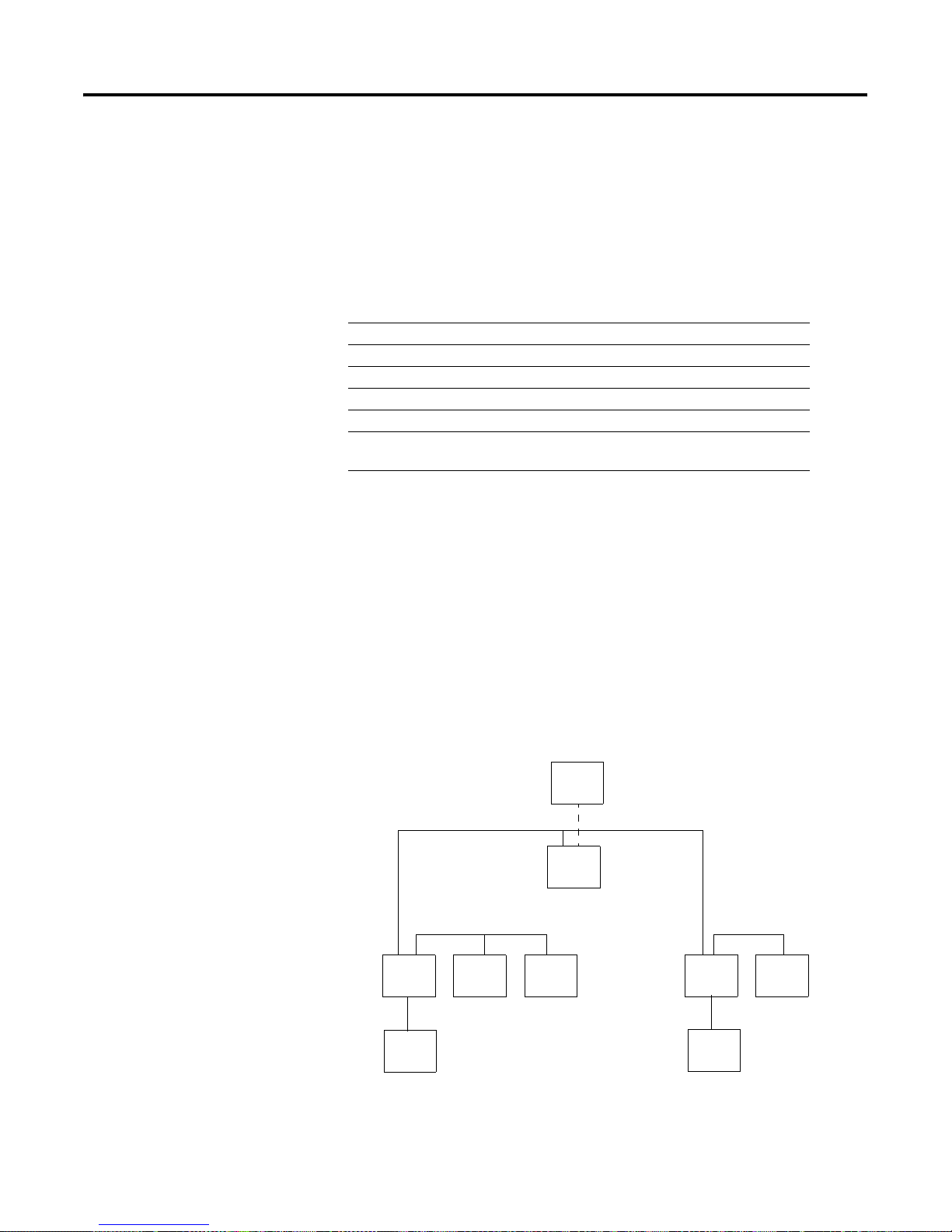
PLC-5/11, -5/20, and -5/26 Controll er Front Panels
keyswitch; selects controller mode
channel 0-25-pin D-shell serial port;
supports standard EIA RS-232C and
RS-423 and is RS-422A compatible
1
Use this port with ASCII or DF1
full-duplex, half-duplex master, and
half-duplex slave protocols. The port's
default configuration supports controller
programming:
DF1 point-to-point
2400 bps
no parity
one stop-bit
BCC error check
no handshaking
PLC-5/11 Controller
PLC-5/20 or -5/26 Controller
battery indicator (red when
the battery is low)
controller RUN/FAULT
indicator (green when
running; red when faulted)
force indicator (amber when
I/O forces are enabled)
channel 0 communication
status indicator (green when
the channel is communicating)
Install memory module here.
Install battery here
channel 1A status indicator
(lights green and red)
8-pin mini-DIN, DH+ programming
terminal connection parallel to
channel 1A
channel 1A communication port; for
the PLC-5/11 controller, the default
configuration is DH+
2
channel 1A communication port;
this 3-pin port is a dedicated DH+ port
1
Channel 0 is optically-coupled (provides high electrical noise immunity) and can be used with most RS-422A
equipment as long as:
termination resistors are not used
the distance and transmission rate are reduced to comply with RS-423 requirements
Configure these 3-pin ports for:
2
remote I/O scanner
remote I/O adapter,
DH+ communication
unused
channel 1B status indicator
(lights green and red)
channel 1B communication port;
its default configuration is remote
I/O scanner
2
PLC-5 family member designation
Publication 1785-UM012D - EN-P - July 2005
Page 22
1-4 Understanding Your Programmable Controller
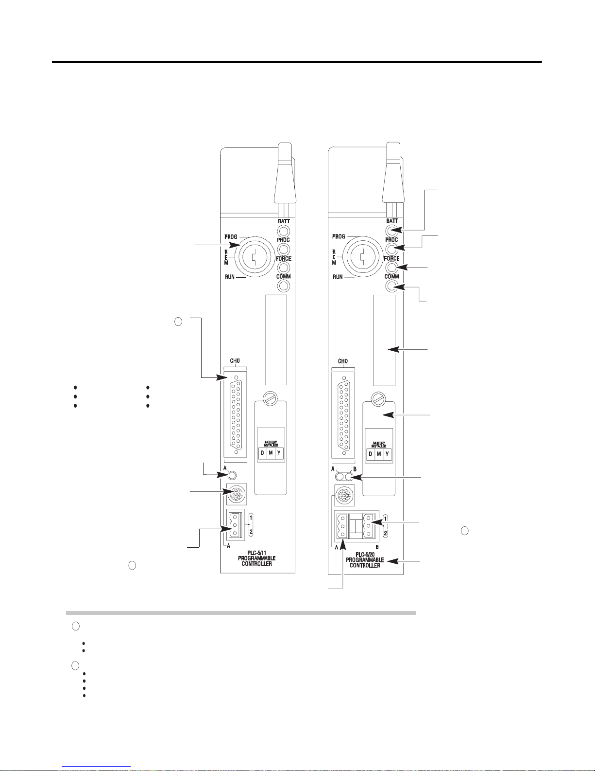
keyswitch; selects controler mode
channel 1A status indicator
(lights green and red)
PLC-5/30 Controller Front Panell
battery indicator (lights red when the
battery is low)
controller RUN/FAULT indicator (green
when running; red when faulted)
force indicator (amber when
I/O forces are enabled)
channel 0 communication status indicator
(green when the channel is communicating)
channel 0-25-pin D-shell serial port; supports standard
EIA RS-232C and RS-423 and is RS-422A compatible
Use this port with ASCII or DF1 full-duplex, half-duplex
master, and half-duplex slave protocols. The port's
default configuration supports processor programming:
DF1 point-to-point
2400 bps
no parity
one stop-bit
BCC error check
no handshaking
1
8-pin mini-DIN, DH+ programming terminal
connection parallel to channel 1A
channel 1A communication port;
its default configuration is DH+
channel 1B communication port;
its default configuration is remote I/O scanner
2
2
Install battery here
Channel 0 is optically-coupled (provides high electrical noise immunity) and can be used with most RS-422
1
equipment as long as:
termination resistors are not used
the distance and transmission rate are reduced to comply with RS-423 requirements
2
Configure these 3-pin ports for:
remote I/O scanner,
remote I/O adapter,
DH+ communication
unused
channel 1B status indicator (lights green and red)
Install memory module here
Use these labels to write information about the
channel: communication mode, station addresses, etc.
PLC-5 family member designation
Publication 1785-UM012D-EN-P - July 2005
Page 23
keyswitch; selects controller mode
channel 2A status indicator
(lights green and red)
Understanding Your Programmable Controller 1-5
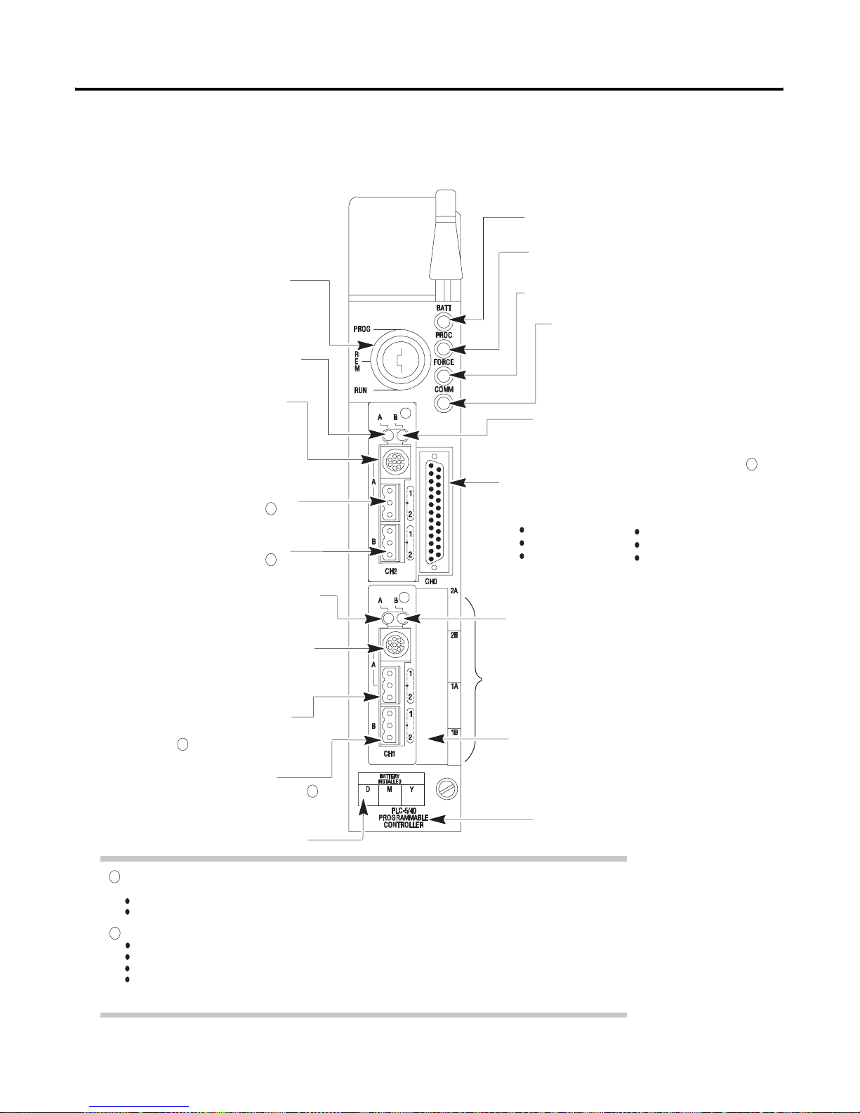
PLC-5/40, -5/46, -5/60, -5/80, and -5/86 Controller Front Panel
battery indicator (red when the battery is low)
controler RUN/FAULT indicator (green when
running; red when faulted)
force indicator (amber when I/O forces are enabled)
channel 0 communication status indicator
(green when the channel is communicating)
8-pin mini-DIN, DH+ programming
terminal connection parallel to channel
2A when channel 2A is configured for
DH+ communications
channel 2A communication port;
its default configuration is unused
2
channel 2B communication port;
its default configuration is unused
2
channel 1A status indicator
(lights green and red)
8-pin mini-DIN, DH+ programming terminal
connection parallel to channel 1A
channel 1A communication port;
its default configuration is DH+
at 57.6 kbps
2
channel 1B communication port;
its default configuration is remote I/O scanner
channel 2B status indicator (lights green and red)
channel 0-25-pin D-shell serial port; supports standard
EIA RS-232C and RS-423 and is RS-422A compatible
1
Use this port with ASCII or DF1 full-duplex, half-duplex
master, and half-duplex slave protocols. The port's
default configuration supports processor programming:
DF1 point-to-point
2400 bps
no parity
one stop-bit
BCC error check
no handshaking
channel 1B status indicator (lights green and red)
Use these labels to write information about the
channel: communication mode, station addresses etc.
Install memory module here
2
Install battery here
1
Channel 0 is optically-coupled (provides high electrical noise immunity) and can be used with most RS-422A
equipment as long as:
termination resistors are not used
the distance and transmission rate are reduced to comply with RS-423 requirements
2
Configure these 3-pin ports for:
remote I/O scanner,
remote I/O adapter,
DH+ communication
unused
PLC-5 family member designation
Publication 1785-UM012D - EN-P - July 2005
Page 24
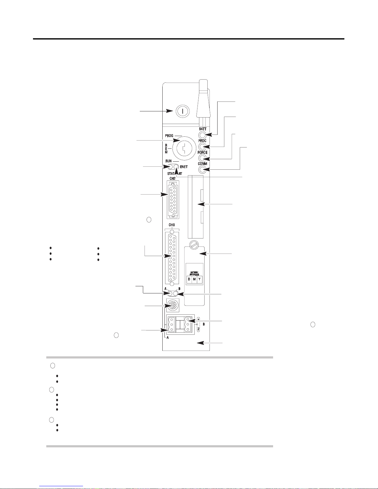
1-6 Understanding Your Programmable Controller
external transceiver fuse
keyswitch; selects controller mode
channel 2 Ethernet status indicator (green when
functioning normally; red when not functioning)
channel 2 communication port;
a 15-pin Ethernet port
channel 0*25-pin D-shell serial port; supports standard
EIA RS-232C and RS-423 and is RS-422A compatible
Use this port with ASCII or DF1 full-duplex, half-duplex
master, and half-duplex slave protocols. The port's
default configuration supports controller programming:
DF1 point-to-point
2400 bps
no parity
one stop-bit
BCC error check
no handshaking
PLC-5/20E Controller Front Pa ne l
1
battery indicator (red when the battery is low)
controller RUN/FAULT indicator (green when
running; red when faulted)
force indicator (amber when I/O forces
are enabled)
channel 0 communication status indicator
(green when the channel is communicating)
channel 2, Ethernet transmit indicator
(green when the channel is communicating)
Install memory module here
Install battery here
channel 1A status indicator
(lights green and red)
8-pin mini-DIN, DH+ programming terminal
connection parallel to channel 1A
channel 1A communication port; its default
configuration is DH+ communication
1
Channel 0 is optically-coupled (provides high electrical noise immunity) and can be used with most RS-422A
equipment as long as:
termination resistors are not used
the distance and transmission rate are reduced to comply with RS-423 requirements
2
Configure these 3-pin ports for:
remote I/O scanner
remote I/O adapter
DH+ communication
unused
Configure this 3-pin port for:
3
remote I/O adapter
DH+ communication
3
PLC-5/20E
Programmable
Controller
channel 1B status indicator
(lights green and red)
channel 1B communication port;
its default configuration is remote I/O scanner
PLC-5 family member designation
2
Publication 1785-UM012D-EN-P - July 2005
Page 25
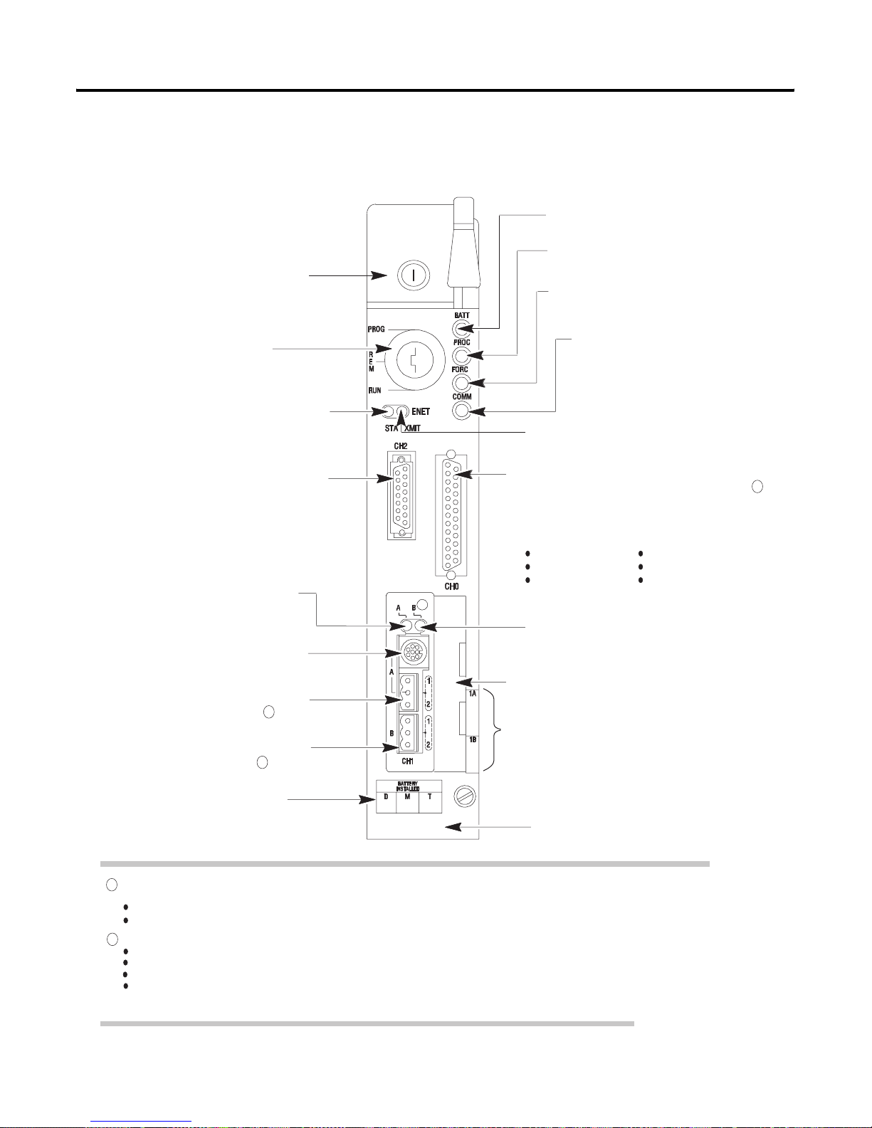
external transceiver fuse
keyswitch; selects controller mode
channel 2 Ethernet status indicator (green when
functioning normally; red when not functioning)
PLC-5/40E and -5/80E Con troller Front Panels
Understanding Your Programmable Controller 1-7
battery indicator (red when the battery is low)
controller RUN/FAULT indicator (green when
running; red when faulted)
force indicator (amber when I/O forces
are enabled)
channel 0 communication status indicator
(green when the channel is communicating)
channel 2, Ethernet transmit indicator (green when
the channel is communicating)
channel 2 communication port;
a 15-pin Ethernet port
channel 1A status indicator
(lights green and red)
8-pin mini-DIN, DH+ programming terminal
connection parallel to channel 1A
channel 1A communication port; its default
configuration is DH+ communication
2
channel 1B communication port; its default
configuration is remote I/O scanner
2
Install battery here
PLC-5/40E
Programmable
Controller
Channel 0 is optically-coupled (provides high electrical noise immunity) and can be used with most RS-422A
1
equipment as long as:
termination resistors are not used
the distance and transmission rate are reduced to comply with RS-423 requirements
2
Configure these 3-pin ports for:
remote I/O scanner
remote I/O adapter
DH+ communication
unused
channel 0-25-pin D-shell serial port; supports standard
EIA RS-232C and RS-423 and is RS-422A compatible
Use this port with ASCII or DF1 full-duplex, half-duplex
master, and half-duplex slave protocols. The port's
default configuration supports controller programming:
DF1 point-to-point
2400 bps
no parity
one stop-bit
BCC error check
no handshaking
channel 1B status indicator (lights green and red)
Install memory module here
Use these labels to write information about the
channel: communication mode, station addresses etc.
PLC-5 family member designation
1
Publication 1785-UM012D - EN-P - July 2005
Page 26
1-8 Understanding Your Programmable Controller
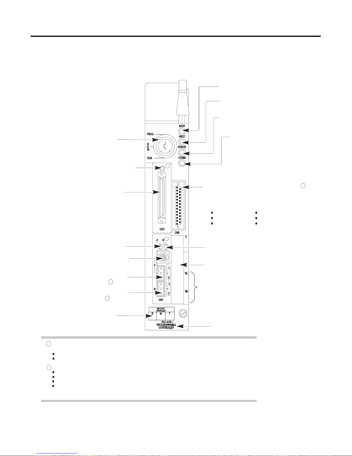
PLC-5/40L and -5/6 0L Controller Front Panels
battery indicator (red when the battery is low)
controller RUN/FAULT indicator (green when
running; red when faulted)
force indicator (amber when I/O forces
are enabled)
keyswitch; selects controller mode
channel 2 extended-local I/O status indicator
(green when functioning normally; red when
not functioning)
channel 2 communication port; a 50-pin,
dedicated extended-local I/O port
channel 1A status indicator
(lights green and red)
8-pin mini-DIN, DH+ programming terminal
connection parallel to channel 1A
channel 1A communication port; its default
2
configuration is DH+ communication
channel 1B communication port; its default
configuration is remote I/O scanner
2
channel 0 communication status indicator
(green when the channel is communicating)
channel 0*25-pin D-shell serial port; supports standard
EIA RS-232C and RS-423 and is RS-422A compatible
Use this port with ASCII or DF1 full-duplex, half-duplex
master, and half-duplex slave protocols. The port's
default configuration supports controler programming:
DF1 point-to-point
2400 bps
no parity
one stop-bit
BCC error check
no handshaking
channel 1B status indicator (lights green and red)
Install memory module here
Use these labels to write information about the
channel: communication mode, station addresses etc.
1
Install battery here
1
Channel 0 is optically-coupled (provides high electrical noise immunity) and can be used with most RS-422A
equipment as long as:
termination resistors are not used
the distance and transmission rate are reduced to comply with RS-423 requirements
Configure these 3-pin ports for:
2
remote I/O scanner,
remote I/O adapter,
DH+ communication
unused
Publication 1785-UM012D-EN-P - July 2005
PLC-5 family member designation
Page 27

Understanding Your Programmable Controller 1-9
Use the keyswitch to change the mode in which a controller is operating.
If You Want to Turn the Keyswitch to
• Run your program.
Outputs are enabled. (Equipment being controlled by the I/O
addressed in the ladder program begins operation.)
• Force I/O.
• Save your programs to a disk drive (during operation).
• Enable outputs.
• Edit data table values.
Notes:
• You cannot create or delete a program file, create or delete
data files, edit online, or change the modes of operation
through the programming software while in run mode.
• You can prevent forcing and data table changes by
usingRSLogix5 programming software to set user control bit
S:26/6.
• Disable outputs (outputs are turned off).
• Create, modify, and delete ladder files, SFC files, or data
files.
• Download to/from a memory module.
• Save/restore programs.
Notes:
• The controller does not scan the program.
• You cannot change the mode of operation through the
programming software while in program mode.
Change between remote program, remote test, and remote run
modes through the programming software.
RUN
PROG
R
E
M
RUN
PROG (program)
PROG
R
E
M
RUN
REM (remote)
Remote run
• Enable outputs.
• Save/restore programs.
• Edit while operating.
Remote program
See the program-mode description above.
Remote test
• Execute ladder programs with outputs disabled.
• Cannot create or delete ladder programs or data files.
• Save/restore programs.
• Edit while operating.
PROG
R
E
M
RUN
Publication 1785-UM012D - EN-P - July 2005
Page 28

1-10 Understanding Your Programmable Controller
Programming Features
This Capability Lets You
Ladder logic program using a language that is representative of relay logic.
Subroutines store recurring sections of program logic that can be accessed from multiple program
Sequential Function Charts
(SFCs)
This table highlights the programming features of a PLC-5 programmable
controller.
Choose this language
• if you are more familiar with ladder logic than with programming languages such
as BASIC
Your plant personnel may be more familiar with ladder logic; consider their needs
as well.
• performing diagnostics
• programming discrete control
files.
A subroutine saves memory because you program repetitive logic only once. The JSR
instruction directs the controller to go to a separate subroutine file within the logic
controller , scan that subroutine file once, and return to the point of departure.
use sequence-control language to control and display the state of a sequential process.
Instead of using one long ladder program for your application, divide the logic into steps
and transitions. A step corresponds to a control task; a transition corresponds to a
condition that must occur before the programmable controller can perform the next
control task. The display of these steps and transitions lets you see what state the
machine process is in at a given time via a flowchart form.
SFCs offer constructs that enable execution of multiple paths of logic, or a single
selected path of logic, as well as the ability to jump forwards and backwards.
Troubleshooting can be reduced to a small routine of logic instead of an entire ladder
file.
SFCs are best for defining the order of events in a sequential process.
Structured text program using a language similar to BASIC.
Choose structured text if you are:
• more familiar with programming languages such as BASIC than with ladder logic
• using complex mathematical algorithms
• using program constructs that repeat or “loop”
• creating custom data-table monitoring screens
Main Control Programs
(MCPs)
separate sequential logic from ladder logic and structured text as a way of modularized
your process and making troubleshooting easier.
Use several main control programs (MCPs) to define one main control program for each
particular machine or function of your process. MCPs accommodate independent or
non-sequential activities.
A main control program can be an SFC file numbered 1-999 or a ladder-logic file or
structured-text program numbered 2-999.
One data table is used by all MCPs (i.e., you do not have a separate data table for each
MCP).
Publication 1785-UM012D-EN-P - July 2005
Page 29
Understanding Your Programmable Controll er 1-11
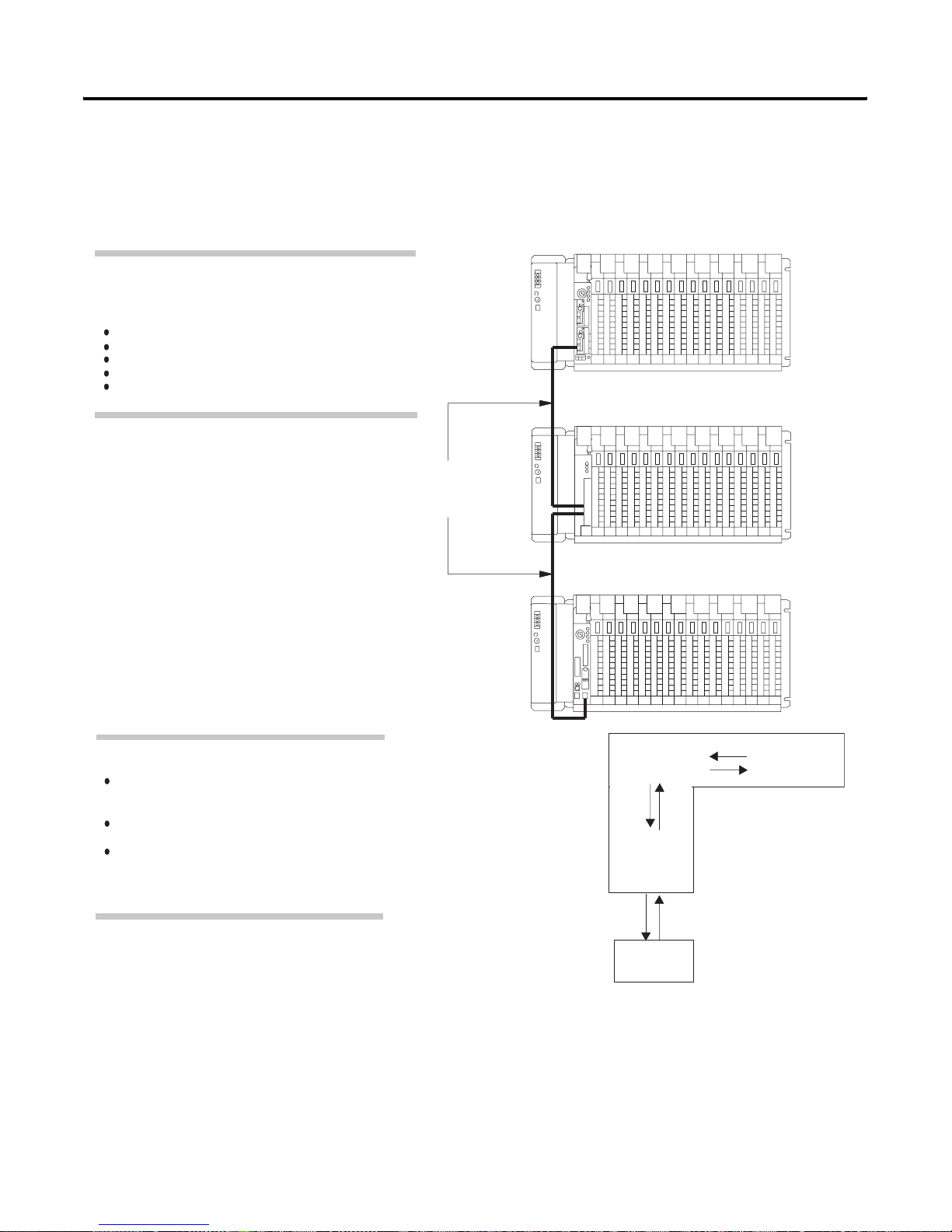
Using a Controller Channel
Configure a remote I/O channel for scanner mode to read and write I/O
information between a controller and an I/O device remotely located from the
as a Remote I/O Scanner
A controller with a channel configured for scanner mode
acts as a supervisory controller for other controllers that
are in adapter mode as well as remote I/O adapter modules.
The scanner-mode PLC-5 controller can:
gather data from node adapter devices in remote I/O racks
process I/O data from 8-, 16-, or 32-point I/O modules
address I/O in 2-, 1-, or 1/2-slot I/O groups
support a complementary I/O configuration
support block-transfer in any I/O chassis
controller.
PLC-5/40
1771-ASB
Remote I/O
Link Cable:
Belden 9463
PLC-5/20
The scanner-mode PLC-5 controller:
transfers discrete data and block-transfer data
to/from modules in remote I/O racks as well as
to/from controllers in adapter mode.
scans remote I/O buffers asynchronously to the
program scan.
updates the input/output image data table from
the remote I/O buffer(s) synchronously to the
program scan
PLC-5 data table
is updated
synchronously to
program scan
(at housekeeping).
Remote I/O buffers
are updated
asynchronously to
the program scan.
PLC-5
Data Table
Output
Remote I/O
Buffer
Output Input
Input
Remote I/O
Link
Controller
-resident
I/O
Publication 1785-UM012D - EN-P - July 2005
Page 30
1-12 Understanding Your Programmable Controller
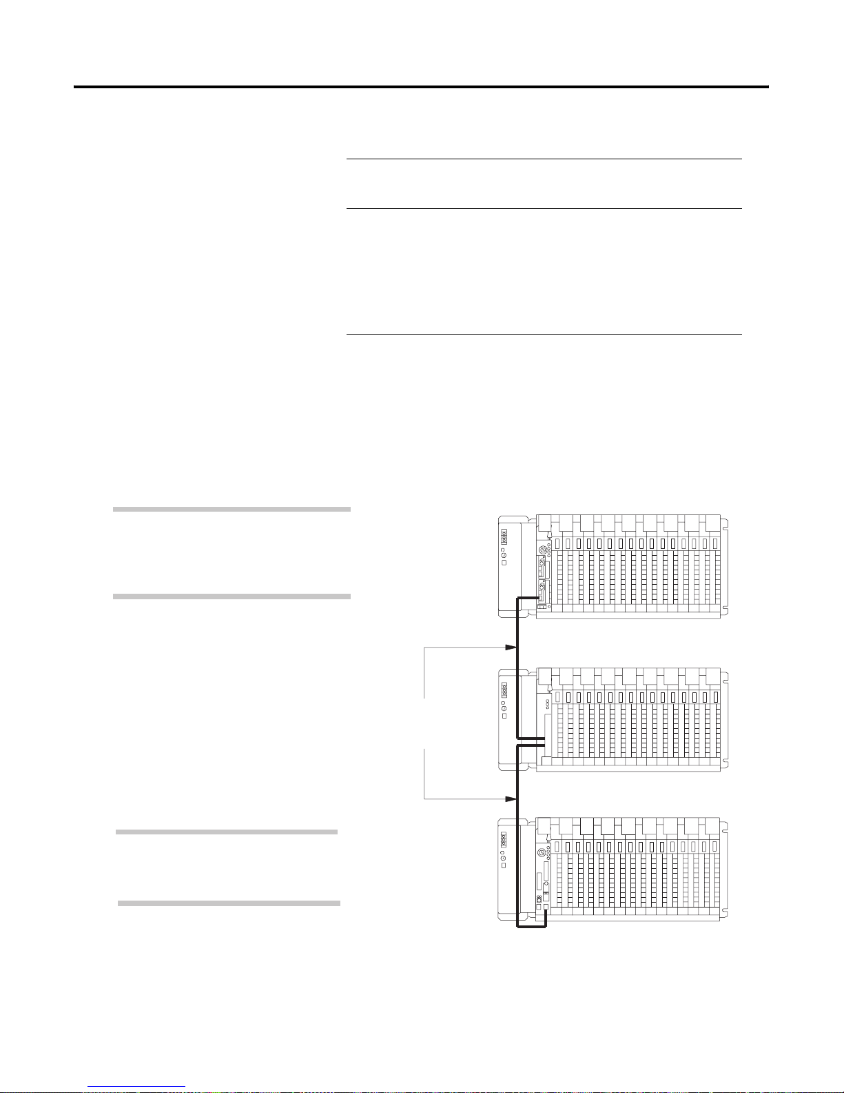
A controller transfers I/O data and status data using:
Using a Controller Channel
as a Remote I/O Adapter
In this example, a PLC-5/40 controller channel is
the supervisory (scanner-mode) controller of the
1771-ASB module and the PLC-5/20 controller.
• discrete
data transfers of 8 words per rack
transfers
occur automatically on the remote I/O network
• block-transfers special data transfers that require ladder logic
instructions to achieve the transfer
allow a transfer of a maximum of 64 words of data
also used to communicate information between a
scanner channel and an adapter-mode controller
channel
Configure a controller channel for adapter mode when you need predictable,
real-time exchange of data between a distributed control adapter-mode
controller channel and a supervisory controller. The remote I/O adapter
channel exchanges data with a supervisory controller.
PLC-5/40
Connect the controllers via the remote I/O link.
You can monitor status between the
supervisory controller and the adapter-mode
PLC-5 controller channel at a consistent rate
(i.e., the transmission rate of the remote I/O link
is unaffected by programming terminals and
other non-control-related communications).
The adapter-mode PLC-5 controller can monitor
and control its controller-resident local I/O while
communicating with the supervisory controller via
a remote I/O link.
1771-ASB
Remote I/O
Link Cable:
Belden 9463
PLC-5/20
Publication 1785-UM012D-EN-P - July 2005
Page 31
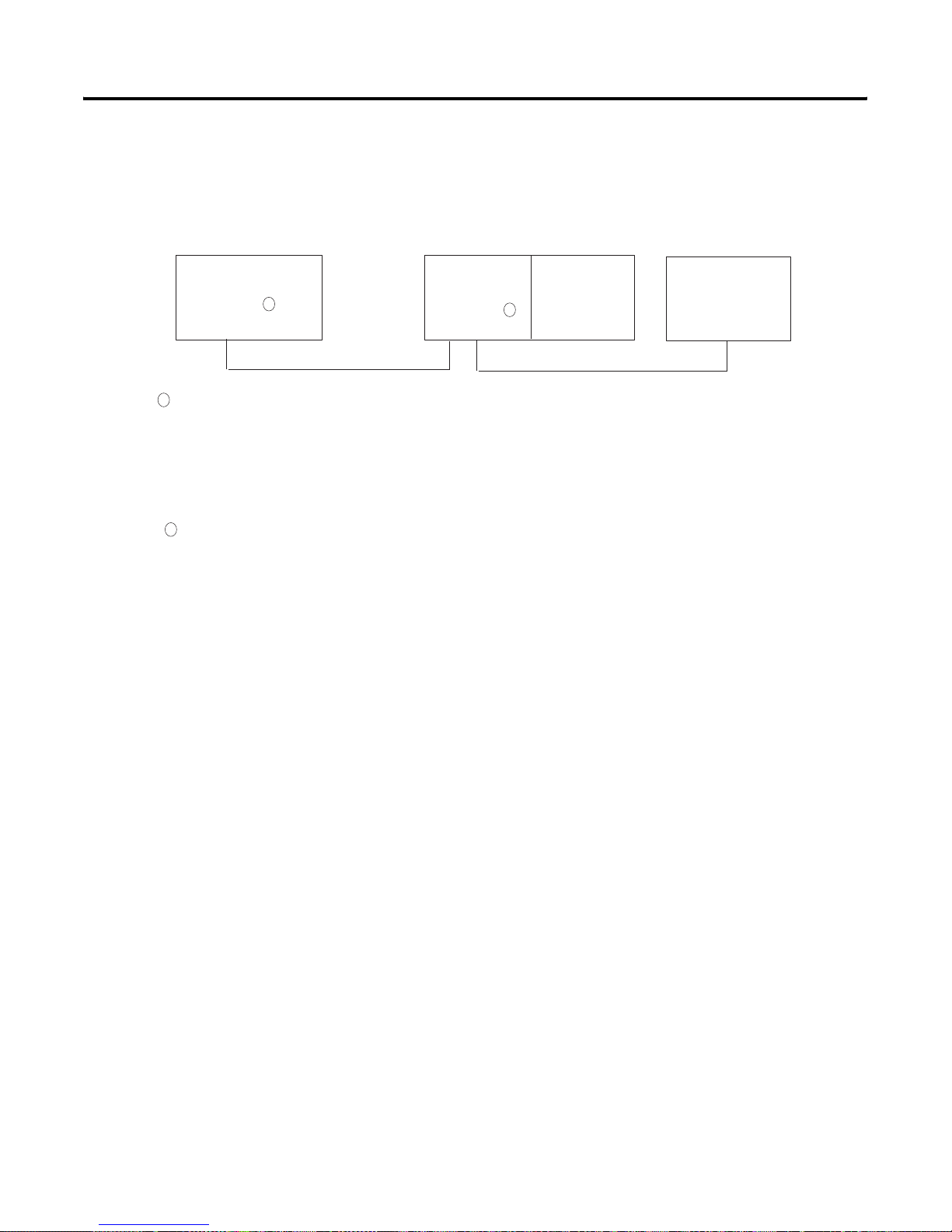
Understanding Your Programmable Controll er 1-13
For Enhanced and Ethernet programmable controller channels in adapter
mode, you do n ot ne ed ladder logic i n the a dapter c ontroll er for block- tran sfer
instructions. You define the block-transfers via an adapter configuration
screen and by defining block-transfer files.
Supervisory
Controller
1
The following programmable controllers can operate as supervisory controllers:
PLC-2/20 and PLC-2/30 controllers
PLC-3 and PLC-3/10 controllers
PLC-5/15 and PLC-5/25E controllers
All Enhanced and Ethernet PLC-5 controllers; separate channels can be configured for a remote I/O scanner and an adapter
PLC-5/V30, PLC-5/V40, PLC-5/V40L, and PLC-5/V80 controllers
PLC-5/250 controllers
All PLC-5 family controllers, except the PLC-5/10, can operate as remote I/O adapter modules
2
1
Remote I/O Link
PLC-5 controller
channel in
adapter mode
1771 I/O
2
Remote I/O Link
PanelView
Publication 1785-UM012D - EN-P - July 2005
Page 32

1-14 Understanding Your Programmable Controller
Using a PLC-5/40L, -5/60L
Programmable Controller
as an Extended-Local I/O
Scanner
A PLC-5/40L or -5/60L controller (channel 2) and an
extended-local I/O adapter module (1771-ALX) form an
extended-local I/O link.
The extended-local I/O link is a parallel link that enables a
PLC-5/40L or -5/60L controller to scan a maximum of 16
extended-local I/O chassis.
Due to the cabling design, you can remove an adapter module
from a chassis on the extended-local I/O link without disrupting
communication to other chassis on the extended-local I/O link.
Important: The PLC-5/40L and -5/60L controllers cannot be
used as extended-local I/O adapters.
Use the extended-local I/O link when you need I/O updates more quickly
than is possible from remote I/O link. An extended-local I/O link provides
faster scan and update time than a remote I/O lin k. The extended-local I/O
link is limited to 30.5 cable-m (100 cable-ft). If an I/O chassis is located more
than 30.5m from the controller, you must use a remote I/O link.
PLC-5/60L
Extended-local
I/O Link Cable:
1771-CXx
1771-ALX
ExtendedLocal
I/O Link
Input
Output
PLC-5 data table
is updated
synchronously to
program scan
(at housekeeping).
Remote I/O buffers
are updated
asynchronously to
the program scan.
PLC-5 data table
OutputInput
Remote
I/O
Buffer
OutputInput
Remote I/O
Link
Input
Output
ControllerResident
Local I/O
Publication 1785-UM012D-EN-P - July 2005
Page 33

Using This Chapter
Selecting and Placing I/O
For Information About Go to Page
Selecting I/O modules 2-1
Selecting I/O module density 2-2
Placing I/O modules in a chassis 2-3
Chapter
2
Selecting I/O Modules
Select I/O modules to interface your PLC-5 controller with machines or
processes that you determine while analyzing your plant operation.
Use the following list and table as guidelines for selecting I/O modules and
operator control interface(s).
• How much I/O is required to control your process(es)?
• Where will you concentrate I/O points for portions of an entire process
when the entire process is distributed over a large physical area?
• What type of I/O is required to control your process(es)?
• What is the required voltage range for each I/O mod ule?
• What is the backplane current required for each I/O module?
• What are the noise and distance limitations for each I/O module?
• What isolation is required for each I/O module?
1 Publication 1785-UM012D - EN-P - July 2005
Page 34

2-2 Selecting and Placing I/O
Guidelines for Selecting I/O Modules
Choose this Type of
I/O Module
Discrete input module
and block I/O module
Discrete output module
and block I/O module
Analog input module Temperature transducers, pressure transducers, load cell
Analog output module Analog valves, actuators, chart recorders, electric motor
Specialty I/O modules Encoders, flow meters, I/O communication, ASCII, RF type
Selecting I/O Module
For these Types of Field Devices or Operati ons
(examples)
Selector switches, pushbuttons, photoelectric eyes, limit
switches, circuit breakers, proximity switches, level
switches, motor starter contacts, relay contacts,
thumbwheel switches
Alarms, control relays, fans, lights, horns, valves, motor
starter , or solenoids
transducers, humidity transducers, flow transducers, and
potentiometers
drives, analog meters
devices, weigh scales, bar-code readers, tag readers,
display devices
The density of an I/O module is the number of controller input or output
image-table bits to which it corresponds. A bidirectional module with 8 input
Density
bits and 8 output bits has a density of 8. I/O module density helps determine
your I/O addressing scheme. See chapter 4 for more information about I/O
addressing.
Explanation
Input modules sense on/off or opened/closed
signals. Discrete signals can be either ac or dc.
Output module signals interface with on/off or
opened/closed devices. Discrete signals can be
either ac or dc.
Convert continuous analog signals into input values
for the PLC controller.
Interpret PLC controller output to analog signals
(generally through transducers) for field devices.
Are generally used for specific applications such as
position control, PID, and external device
communication.
Publication 1785-UM012D-EN-P - July 2005
Use these guidelines for selecting I/O module density:
Choose this I/O Density If You
8-point I/O module • currently use 8-point modules
• need integral, separately-fused outputs
• want to minimize cost per module
16-point I/O module • currently use 16-point modules
• need separately-fused outputs with a special
wiring arm
32-point I/O module • currently use 32-point modules
• want to minimize number of modules
• want to minimize the space required for I/O
chassis
• want to minimize cost per I/O point
Page 35

Selecting and Placing I/ O 2-3
Placing I/O Modules in a
Chassis
Module placement priority:
1. block-transfer modules (all types)
2. dc input modules
3. dc output modules
4. ac input modules
5. ac output modules
Place block-transfer modules according to these guidelines:
Place as many modules as possible for which you need
fast block-transfer times in your controller-resident local
I/O chassis.
Place modules in which block-transfer timing is not as
critical in remote I/O chassis.
Ac output modules should always be the furthest I/O
modules away from any block-transfer modules in the
same chassis.
Place I/O modules in a chassis depending on the electrical characteristics of
the module. The placement is made left to right, with the left-most position
being closest in the chassis to the PLC-5 controller or the I/ O adapter module.
The placement order is as follows:
Priority:
P
L
C
/
A
S
B
1
Block
Transfer
212334455
Block
Transfer
dc
inputdcinputdcoutputdcoutputacinputacinputacoutputacoutput
lowV highV
Place input and output modules according to
these guidelines:
left to right
lowest voltage to highest voltage
For optimal speed using discrete I/O, use the
following module-placement priority scheme:
1. controller chassis
2. extended-local I/O chassis
3. remote I/O chassis
empty
Publication 1785-UM012D - EN-P - July 2005
Page 36

2-4 Selecting and Placing I/O
Notes
Publication 1785-UM012D-EN-P - July 2005
Page 37

Using This Chapter
Placing System Hardware
For Information About Go to Page
Determining the proper environment 3-1
Protecting your controller 3-3
Avoiding electrostatic damage 3-3
Laying out your cable raceway 3-4
Laying out your backpanel spacing 3-5
Grounding your system 3-6
Chapter
3
Determining the Proper
Environment
Place the controller in an environment with conditions that fall within these
guidelines:
Environmental Condition Acceptable Range
Operating temperature 0 to 60° C (32 to 140° F)
Storage temperature -40 to 85° C (-40 to 185° F)
Relative humidity 5 to 95% (without condensation)
Separate your programmable controller system from other equipment and
plant walls to allow for convection cooling. Convection cooling draws a
vertical column of air upward over the controller. This cooling air must not
exceed 60° C (140° F) at any point immediately below the controller . If the air
temperature exceeds 60° C, install fans that bring in filtered air or recirculate
internal air inside the enclosure, or install air-conditioning/heat-exchanger
units.
To allow for proper convection cooling in enclosures containing a
controller-resident chassis and remote I/O chassis, follow these guidelines.
1 Publication 1785-UM012D - EN-P - July 2005
Page 38
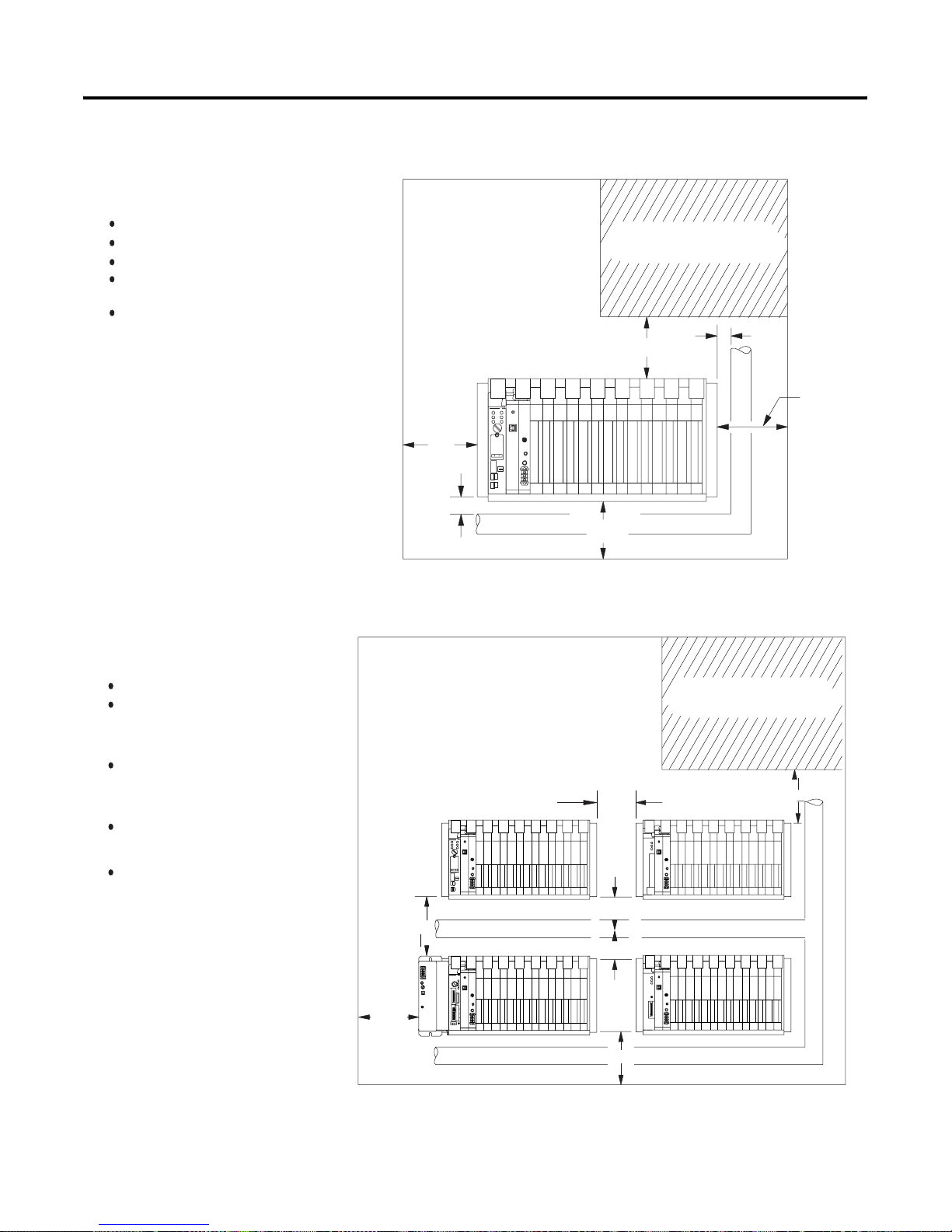
3-2 Placing System Hardware
Minimum spacing requirements for a
controller-resident chassis:
Mount the I/O chassis horizontally.
Allow 153 mm (6 in) above and below the chassis.
Allow 102 mm (4 in) on the sides of each chassis.
Allow 51 mm (2 in) vertically and horizontally between
any chassis and the wiring duct or terminal strips.
Leave any excess space at the top of the enclosure,
where the temperature is the highest.
102mm
(4")
Area reserved for disconnect,
transformer, control relays, motor
starters, or other user devices.
153mm
(6")
51mm
(2")
102mm
(4")
Minimum spacing requirements for a remote
I/O and extended-local I/O chassis:
Mount the I/O chassis horizontally.
Allow 153 mm (6 in) above and below all
chassis. When you use more than one
chassis in the same area, allow 152.4 mm (6
in) between each chassis.
Allow 102 mm (4 in) on the sides of each
chassis. When you use more than one
chassis in the same area, allow 101.6 mm (4
in) between each chassis.
Allow 51 mm (2 in) vertically and horizontally
between any chassis and the wiring duct or
terminal strips.
Leave any excess space at the top of
the enclosure, where the temperature is
the highest.
153mm (6")
51mm(2")
153mm
Wiring Duct
(6")
Area reserved for disconnect,
transformer, control relays, motor
starters, or other user devices.
102mm 153mm
(4")
(6")
51mm (2")
Wiring Duct
51mm (2")
13081
Publication 1785-UM012D-EN-P - July 2005
102mm
(4")
102mm
(4")
153mm (6")
Wiring Duct
18749
Page 39

Placing System Hardware 3-3
Protecting Your Controller
Preventing Electrostatic
Discharge
You pro vi d e th e en cl osu r e fo r y o ur cont ro ll er s y st em. This en clo su re pro te ct s
your controller system from atmospheric contaminants such as oil, moisture,
dust, corrosive vapors, or other harmful airborne substances. To help guard
against electromagnetic interference (EM I) and radio fre quency in terference
(RFI), we recommend a steel enclosure.
Mount the enclosure in a position where you can fully open the doors. You
need easy access to controller wiring and related components so that
troubleshooting is c onvenient.
When you choose the enclosure size, allow extra space for transformers,
fusing, disconnect switch, master control relay, and terminal strips.
ATTENTION
Under some conditions, electrostatic discharge can degrade
performance or damage the controller. Read and observe
the following precautions to guard against electrostatic
damage.ESD protection
• Wear an approved wrist strap grounding device when
handling the controller.
• Touch a grounded object to discharge yourself before
handling the controller.
• Do not touch the backplane connector or connector
pins.
Publication 1785-UM012D - EN-P - July 2005
Page 40

3-4 Placing System Hardware
Laying Out Your Cable
Raceway
The raceway layout of a system reflects where the different types of I/ O
modules are placed in I/O chassis. Therefore, you should determine
I/O-module placement prior to any layout and routing of wires. When
planning your I/O-module placement, however, segregate the modules based
on the conductor categories published for each I/O module so that you can
follow these guidelines. These guidelines coincide with the guidelines f or “the
installation of electrical equipment to minimize electrical noise inputs to
controllers from external sources” in IEEE standard 518-1982.
To plan a raceway layout, do the following:
• categorize conductor cables
• rou te conducto r ca b l e s
Categorize Conductors
Segregate all wires and cables into categories as described in the Industrial
Automation Wiring and Grounding Guidelines, publication 1770-4.1. See the
installation data for each I/O module that y ou are using for inf ormation about
its classification.
Route Conductors
To guard against coupling noise from one conductor to an other, follow the
general guidelines for routing cables described in the Industrial Automation
Wiring and Grounding Guidelines, publication 1770-4.1. You should follow
the safe grounding and wiring practices called out in the National Electrical
Code (NEC, published b y the National Fire Protection Association, in Quincy,
Massachusetts), and local electrical codes.
Publication 1785-UM012D-EN-P - July 2005
Page 41

Placing System Hardware 3-5
Laying Out Your
Backpanel Spacing
1771-A1B
1771-A2B
1771-A3B1
1771-A4B
Power
Connector
193mm
(7.60")
Side
Use 6.35 mm (0.25 inch) mounting bolts to attach the I/O chassis to the
enclosure backpanel.
Chassis Dimensions (Series B)
315mm
(12.41")
591mm
(23.25")
337mm
(13.25")
464mm
(18.25")
210mm
(8.25")
16-slot 1771
12-slot
8-slot
4-slot
254mm
(10")
1771-A3B
171mm
(6.75")
1
217mm
(8.54")
Side
Total maximum depth dimension per installation will be dependent upon module wiring and connectors.
1
339mm
(13.53")
483mm
(19.01")
229mm
(9.01")
465mm
(18.31")
484mm
(19")
Front
610mm
(24.01")
356mm
(14.01")
16-slot 1771-A4B
12-slot 1771-A3B1
8-slot 1771-A2B
4-slot 1771-A1B
9mm
(.34")
26mm
(1.02")
178mm
(7")
130mm
(5.10")
12450-I
Publication 1785-UM012D - EN-P - July 2005
Page 42
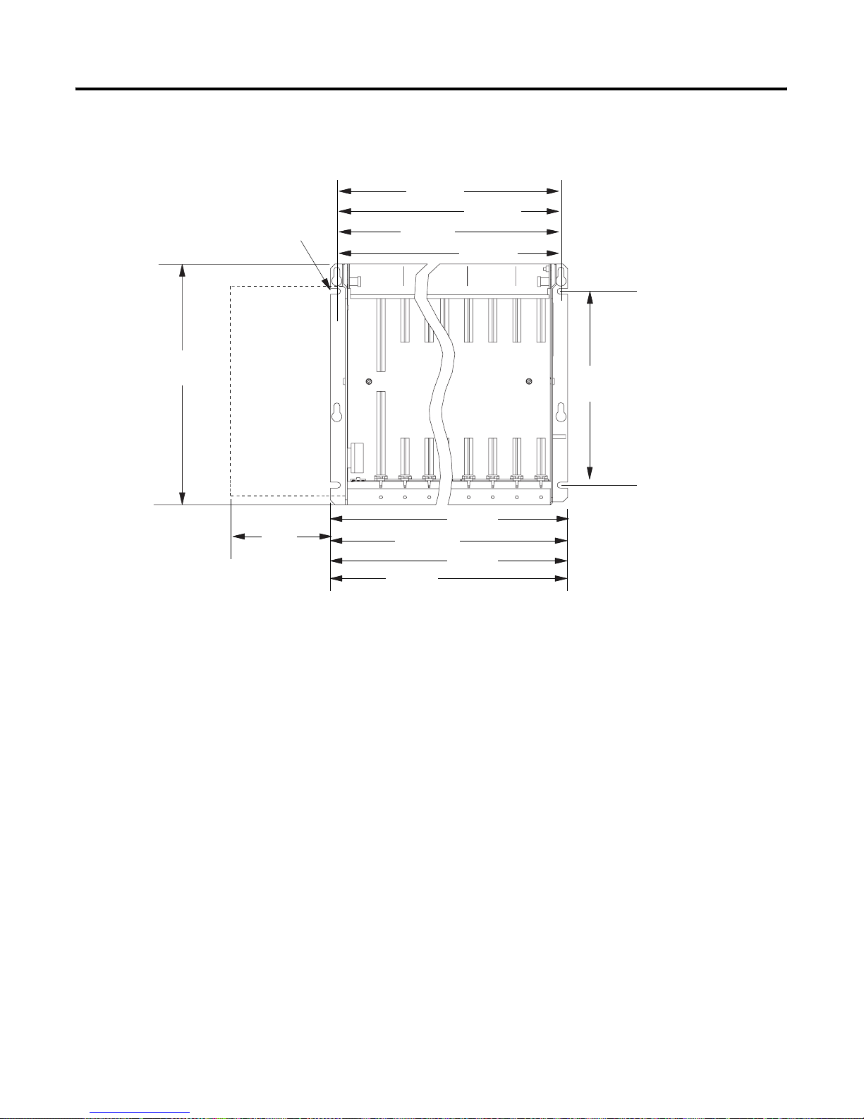
3-6 Placing System Hardware
I/O Chassis and External Power Supply Dimensions
591mm
Use .25" dia
mounting bolts
(4 places)
315mm
(12.41")
Clearance depth is 204mm (8") for 8 I/O connection points per module.
External
Power
Supply
91mm
(3.6")
(23.25")
337mm
(13.25")
483mm
(19.01")
229mm
(9.01")
464mm
(18.25")
210mm
(8.25")
610mm
(24.01")
356mm
(14.01")
16-slot
12-slot
8-slot
4-slot
254mm
(10")
16-slot 1771-A4B
12-slot 1771-A3B1
8-slot 1771-A2B
4-slot 1771-A1B
12451-I
Grounding Your System
Publication 1785-UM012D-EN-P - July 2005
For more information on proper grounding guidelines, see the Industrial
Automation Wiring and Grounding Guidelines, publication 1770-4.1.
Page 43
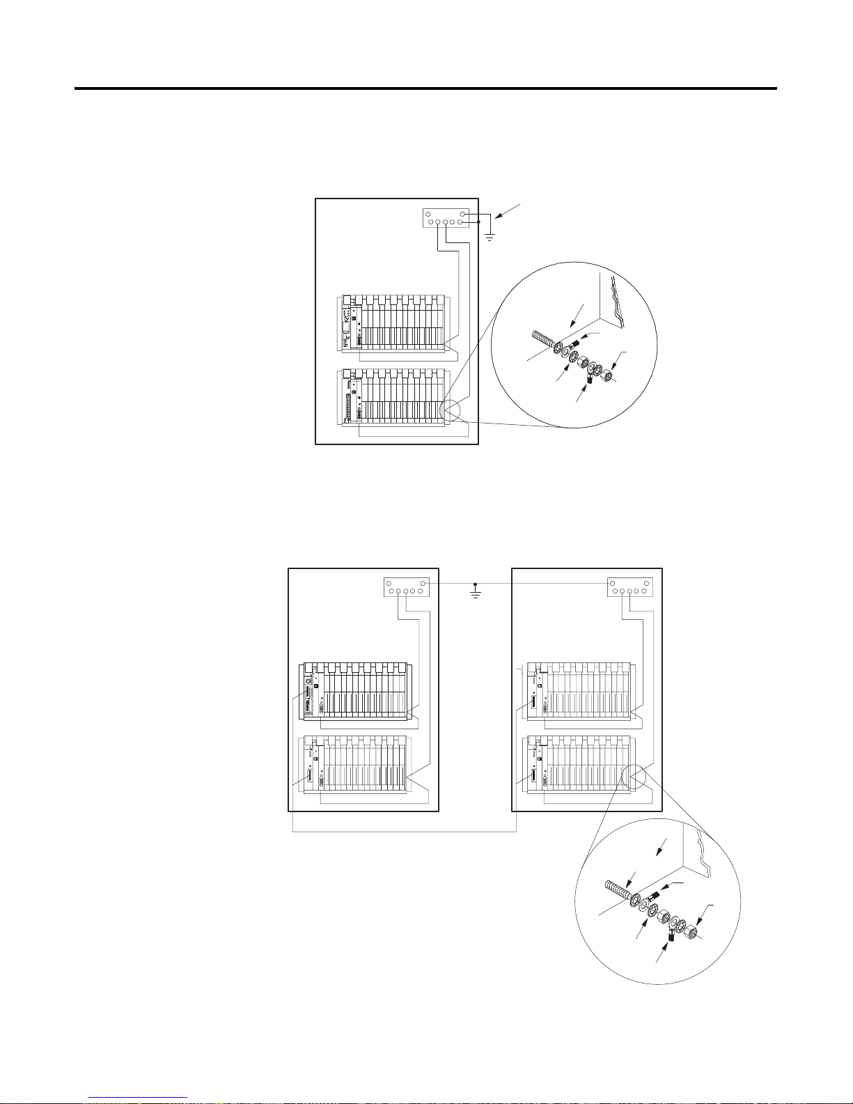
Placing System Hardware 3-7
Enclosure Enclosure
Recommended Grounding Configuration for Remote I/O Systems
Enclosure
Ground
Bus
Grounding Electrode Conductor
To Grounding
Electrode
System
I/O Chassis Wall
Star
Washer
Ground Lug
Ground
Lug
Nut
15561
Required Grounding Con f i guration for Extended-Local I /O Systems
Ground
Bus
Ground
Bus
To
Grounding
Electrode
System
(single
point only)
Extended-Local I/O Cables
I/O Chassis
Wall
I/O Chassis
Ground Stud
Ground
Lug
Nut
Star
Washer
Ground Lug
18585
Publication 1785-UM012D - EN-P - July 2005
Page 44

3-8 Placing System Hardware
Notes
Publication 1785-UM012D-EN-P - July 2005
Page 45

Using This Chapter
Chapter
Addressing I/O and Controller Memory
For Information About Go to Page
I/O addressing concept 4-1
Choosing an addressing mode 4-3
Addressing block-transfer modules 4-7
Addressing summary 4-7
Assigning racks 4-8
Understanding PLC-5 controller memory 4-10
Addressing 4-16
Effectively Using I/O Memory 4-24
4
I/O Addressing Concept
Classification Term Relation to Controller Memory
A specific terminal on an I/O module that
occupies a space in controller memory
I/O terminals that when combined occupy 1
word in controller’s input image table and 1
word in the controller’s output image table.
Controller memory needs to be grouped so that
related I/O groups can be considered a unit.
Since the main purpose of a programmable controller is to control inputs and
outputs of field devices like switches, valves, and thermocouples, these inputs
and outputs must occupy a location in the controller memory so that they can
be addressed in your control program. Each terminal on an input or output
module that can be wired to a field device occupies a bi t within controll er
memory. The part of controller memory that houses I/O addresses is the
input image table and the output image table.
I/O addressing helps connect the physical location of an I/O module terminal
to a bit location in the controller memory. I/O addressing is just a way to
segment controller memory. The segmentation is as follows:
terminal or
point
I/O group 16 input bits = 1 word in controller’s input image table
I/O rack 128 input bits and 128 output bits, or8 input words and 8 output words,
The density of an I/O module, i.e., 8-point, 16-point, 32-point, directly
relates to the amount of memory (bits) the module occupies in controller
memory. For example, a 16-point input module occupies 16 bits in the
controller’s input image table.
16 output bits = 1 word in the controller’s output image table
or 8 I/O groups
1 Publication 1785-UM012D - EN-P - July 2005
Each PLC-5 controller has a finite amount of racks it can support. For
example, a PLC-5/30 can support 8 I/O racks.
The controller always occupies at least one I/O rack for itself, rack 0 by
default.
Page 46

4-2 Addressing I/O and Controller Memory
The figure below shows the relationship between an I/O terminal and its
location in controller memory.
I/O Addressing as It Relates to an I/O Terminal
rack number 01
I/O group number 4
A
B
C
D
00
01
02
03
04
05
06
07
10
11
12
13
14
15
16
17
E
Input Module
(1771-IAD)
17 16 15 14 13 12 11 10 07 06 05 04 03 02 01 00
Output Image Table
17 16 15 14 13 12 11 10 07 06 05 04 03 02 01 00
Input Image Table
04
17 16 15 14 13 12 11 10 07 06 05 04 03 02 01 00
I/O group number 5
word
address
00
05
07
00
04
07
rack number 01
Output Module
(1771-OAD)
A
B
C
D
00
01
02
03
04
05
06
07
10
11
12
13
14
15
16
17
E
Notice how input and output
image file addresses
correspond to hardware.
Publication 1785-UM012D-EN-P - July 2005
I:014
| | ( )
12
O:015
07
I:014/12
I for input or O for output
2-digit I/O rack number
I/O group number (0-7)
input or output number (0-7,10-17) (bit)
I/O image table is
addressed octally.
Now that you are familiar with how controller memory is segmented to
address a specific I/O term inal, the next section explains available addressing
modes. These modes let you define the relationship between an I/O chassis
slot and an I/O group (16 input bits and 16 output bits).
Page 47

Addressing I/O and Con troller Memory 4-3
Choosing an Addressing
For each I/O chassis in your syst em, you must define how man y I/O chassis
slots make up an I/O group (1 word each in the input image table and output
Mode
image table); this choice is the chassis’ addressing mode. Choose from among
these available modes:
2-slot addressing
2 I/O chassis slots = 1 I/O group = 1 input image word and 1 output image
word = 16 input bits and 16 output bits.
16 bits input 16 bits output
1-slot addressing
1 I/O chassis slot = 1 I/O group = 1 input image word and 1 output image
word = 16 input bits and 16 output bits.
Controller memory
Rack x
Output Image Table
Word #
x
x
x
x
x
x
x
x
16 bits input and 16 bits output
1/2-slot addressing
1/2 of an I/O chassis slot = 1 I/O group = 1 input image word and 1 output image
word = 16 input bits and 16 output bits.
16 bits input and 16 bits output
When you place your I/O modules in the I/O chassis slots, the module’s
density determines how quickly I/O groups form. For example, let’s choose
1-slot addressing and see how 8-, 16-, and 32-point I/O modules fill controller
memory.
Word #
Input Image Table
x
x
x
x
x
x
x
x
Publication 1785-UM012D - EN-P - July 2005
Page 48

4-4 Addressing I/O and Controller Memory
0 1
18-and 16-point Example
2 3
1-slot addressing (1 I/O chassis slot = 1 I/O group = 1 input image
word and 1 output image word = 16 input bits and 16 output bits.)
Controller memory
Rack x
Input
Terminals
00
01
02
03
04
05
06
07
Group 0
An 8-point I/O module occupies
8 bits in a word. See
1
4 5
Input
Termi
nals
10
11
12
13
14
15
16
17
Input
Terminals
00
01
02
03
04
05
06
07
Group 2 Group 3
Two 8-point input modules occupy 8
bits of each group. See
6 7
Input
Terminals
2
00
01
02
03
04
05
06
07
Word #
3
4
Word #
1
2
3
4
Output Image Table
0
1
2
3
4
5
6
7
0017 bits
Input Image Table
0
1
2
3
4
5
6
7
0017 bits
Input
Terminals
00
01
02
03
04
05
06
07
Output
Terminals
00
01
02
03
04
05
06
07
Group 4 Group 5 Group 6 Group 7
An 8-point input module in group 4
occupies the first eight bits of input
word 4. The 8 point output module
occupies the first 8-output bits in
output word 5. See
3
Publication 1785-UM012D-EN-P - July 2005
Input
Terminals
00
01
02
03
04
05
06
07
10
11
12
13
14
15
16
17
Output
Terminals
16-point I/O modules occupy 16 bits,
an entire word, in the image table.
See
4
00
01
02
03
04
05
06
07
10
11
12
13
14
15
16
17
If you were to address the device attached to
this output circuit in your control program, the
address would be O:xx7/17.
Page 49

32-point input module
0 1
Addressing I/O and Con troller Memory 4-5
32-point Example
1-slot addressing (1 I/O chassis slot = 1 I/O group = 1 input image
word and 1 output image word = 16 input bits and 16 output bits.)
Controller memory
Rack x
32-point input module
Group 0
32-point I/O modules use the entire word
of their group and borrow the entire word
of the next group. See .
1
Since the module is in group 0 and the
inputs for group 0 and group 1 are used,
you must:
install an output module in group 1
or leave the slot empty
0 1
32-point output module
Since the input image table for group 1 is unavailable because it is
being used by the input module of group 0, installing a 32-point output
module makes use of output image table of group 0 and 1. See .
You can also install 8- or 16-point output modules. But you cannot
install another input module since all the input image space for groups
0 and 1 are used by the input module of group 0.
Word #
1
Word #
2
Output Image Table
0
1
2
3
4
5
6
7
0017 bits
Input Image Table
0
1
2
3
4
5
6
7
0017 bits
2
Group 0 Group 1
Publication 1785-UM012D - EN-P - July 2005
Page 50

4-6 Addressing I/O and Controller Memory
When planning your system de sign, con sider the dens ities o f the I/O mo dules
you are using and choose an addressing mode that most efficiently uses
controller memory.
Example of Efficient I/O Image Table Use.
2-slot addressing (2 I/O chassis slot = 1 I/O group = 1 input image
word and 1 output image word = 16 input bits and 16 output bits.)
Controller memory
Rack x
Input
Terminals
00
01
02
03
04
05
06
07
10
11
12
13
14
15
16
17
Output
Terminals
00
01
02
03
04
05
06
07
10
11
12
13
14
15
16
17
Group 0
16-point I/O modules occupy 16 bits, an entire word, in
the image table.
Installing as a pair a 16-point input module and a
16-point output module efficiently uses the image table.
Define the addressing mode for each I/O chassis by setting the chassis
backplane switch assembly. For more informa tion, see Appendix E.
Word #
Word #
Output Image Table
0
1
2
3
4
5
6
7
0017 bits
Input Image Table
0
1
2
3
4
5
6
7
0017 bits
Publication 1785-UM012D-EN-P - July 2005
Page 51

Addressing I/O and Con troller Memory 4-7
Addressing
Block-Transfer Modules
Addressing Summary
Addressing
Mode Guidelines
2-slot • Two I/O module slots = 1 group
1-slot • One I/O module slot = 1 group
1/2-slot • One half of an I/O module slot = 1 group
Block-transfer modules occupy 8 bits in the controller’s I/O image table.
Since all block-transfer modules are bidirectional, they cannot be used to
complement either input or output modules.
To Address Use
single slot modules assigned I/O rack and group number of the slot in which the
module resides and 0 for the module number
When using 1/2-slot addressing, use the assigned rack
number and the lowest group number and 0 for the module
number.
double-slot modules assigned rack number and the lowest group number and 0 for
the module number
Use this table as a quick reference for addressing.
• Each physical 2-slot I/O group corresponds to one word (16 bits) in the input image table and
one word (16 bits) in the output image table
• When you use 16-point I/O modules, you must install as a pair an input module and an output
module in an I/O group; if you use an input module in slot 0, you must use an output module in
slot 1 (or it must be empty). This configuration gives you the maximum use of I/O.
• You cannot use a block-transfer module and a 16-point module in the same I/O group because
block-transfer modules use 8 bits in both the input and output table. Therefore, 8 bits of the
16-point module would conflict with the block-transfer module.
• You cannot use 32-point I/O modules.
• Assign one I/O rack number to eight I/O groups.
• Each physical slot in the chassis corresponds to one word (16 bi ts) in the input image table and
one word (16 bits) in the output image table
• When you use 32-point I/O modules, you must install as a pair an input module and an output
module in an even/odd pair of adjacent I/O group; if you use an input module in slot 0, you must
use an output module in slot 1 (or it must be empty). This configuration gi ves you the maximum
use of I/O.
• Use any mix of 8- and 16-point I/O modules, block-transfer or intelligent modules in a single I/O
chassis. Using 8-point modules results in fewer total I/O.
• Assign one I/O rack number to eight I/O groups.
• Each physical slot in the chassis corresponds to two words (32 bits) in the input image table
and two words (32 bits) in the output image table
• Use any mix of 8-, 16-, and 32-point I/O or block-transfer and intelligent modules. Using 8-point
and 16-point I/O modules results in fewer total I/O.
• With the controller-resident local rack set for 1/2-slot addressing, you cannot force the input
bits for the upper word of any slot that is empty or that has an 8-point or 16-point I/O module.
For example, if you have an 8-point or a 16-point I/O module in the first slot of your local rack
(words 0 and 1 of the I/O image table, 1/2-slot addressing), you cannot force the input bits for
word 1 (I:001) on or off.
• Assign one I/O rack number to eight I/O groups.
Publication 1785-UM012D - EN-P - July 2005
Page 52

4-8 Addressing I/O and Controller Memory
Assigning Racks
The number of racks in a chassis depends on the chassis size and the
addressing mode:
If Using this
Chassis Size
4-slot 1/4 rack 1/2 rack 1 rack
8-slot 1/2 rack 1 rack 2 racks
12-slot 3/4 rack 1-1/2 racks 3 racks
16-slot 1 rack 2 racks 4 racks
TIP
2-slot Addressing,
Results In
1-slot Addressing,
Results In
1/2-slot Addressing,
Results In
When assigning rack numbers, use the following guidelines:
• One I/O rack number is eight I/O groups, regardless of
the addressing mode that you select.
• You can assign from one to four racks in your
controller-resident local chassis (128 inputs and 128
outputs) de pending on the chassis size and addressing
mode. You cannot split a controller-resident local I/O
rack over two or more chassis or assign unused
controller- r esident local I/O groups t o r emote I/O racks.
• The default address of the controller-resident local rack is
0.
• You cannot split racks across remote I/O and
extended-local I/O links. For example, if an 8-slot
extended-local I/O chassis is configured as I/O groups
0-3 of I/O rack 2, an 8-slot remote I/O c hass is ca nnot b e
configured as I/O groups 4-7 of I/O rack 2. For more
information about addressing extended-local I/O, see
chapter 8.
• When using complementary I/O addressing, treat
complementary rack addresses individually when
grouping racks; primary rack numbers are separate from
complement rack numbers.
• If you are not using the autoconfiguration function, group
together 1/4-racks and 1/2-racks of each logical rack on
the configuration screen of your programming software.
Do not intersperse these with other rack numbers. For
example, your programming software has a screen with
the following information for defining racks:
Group together 1/4 racks
and 1/2 racks
Publication 1785-UM012D-EN-P - July 2005
Rack Starting Rack Range Fault Inhibit Reset Retry
Address Group Size
1 0 1/4 010-011 I 0 0
1 2 1/4 012-013 0 0 0
1 4 1/4 014-015 0 0 0
2 0 1/4 020-021 0 0 0
2 2 1/4 022-023 0 0 0
2 4 1/2 024-027 0 0 0
3 0 1/4 030-031 0 0 0
17 0 FULL 170-177 0 0 0
Page 53
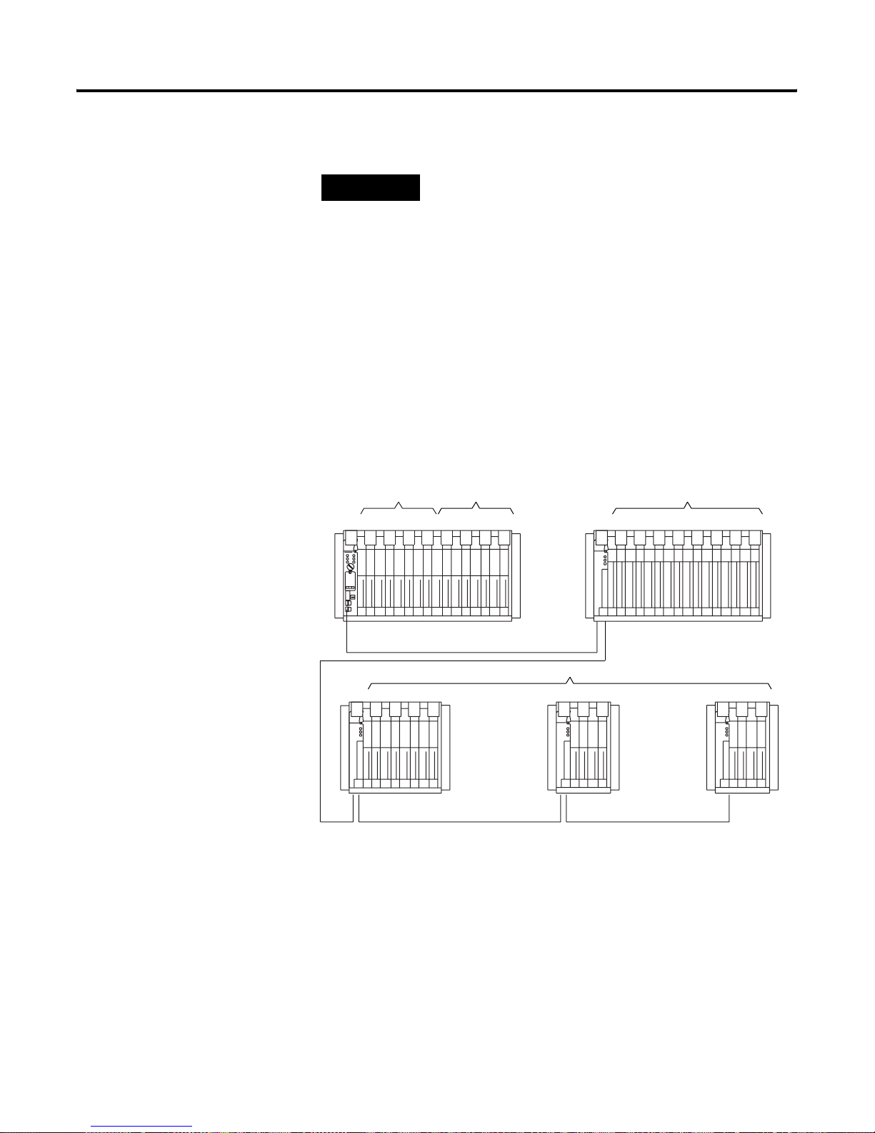
Addressing I/O and Con troller Memory 4-9
TIP
When assigning remote I/O rack numbers, use these
guidelines:
• A single remote I/O scanner channel can support up to 32 devices
but only 16 rack numbers. For more information, see chapter 6.
• Limit the number of remote I/O rack numbers to those that your
PLC-5 controller can support.
• The PLC-5 controller and the 1771-ASB adapter module
automatically allocate the next higher rack number(s) to the
remaining I/O groups of the chassis. For example, if you select
1/2-slot addressing for your controller-resident local chassis and
you are using a 16-slot (1771-A4B) chassis, the controller will
address racks 0, 1, 2, and 3 in this chassis.
• You can assign a remote I/O rack to a fraction of a chassis, a
single I/O chassis, or multiple I/O chassis as shown below.
I/O Rack No. 0
01 23 45 67 01 23 45 67 01234567
I/O Rack No. 1
One 16-slot chassis, two racks
I/O Rack No. 3
0123
One 8-slot chassis, 1/2 rack Two 4-slot chassis, 1/4 rack each
One 16-slot chassis, one rack
5
4
67
16466
Publication 1785-UM012D - EN-P - July 2005
Page 54

4-10 Addressing I/O and Controller Memor y
Understanding PLC-5
Controller Memory
Controller memory is divided into two basic areas:
Storage Areas Description
Data All of the data the controller examines or changes is stored in files in data
storage areas of memory. These storage areas store:
• Data received from input modules
• Data to be sent to output module s; thi s data repr ese nt s decis ions mad e
by the logic
• Intermediate results made by the logic
• Preloaded data such as presets and recipes
• Control instructions
•System status
Program Files You create files for program logic, depending on the method you are using:
ladder logic, sequential function charts, and/or structured text. These files
contain the instructions to examine inputs and outputs and return results.
Publication 1785-UM012D-EN-P - July 2005
Page 55

Integer
Files
File 7
Integer Data
Table Files
File #
Integer
File 7
File 999
Words
(Sample Data)
1020
64
7779
2
Addressing I/O and Controller Memory 4-11
Understanding Data Storage (Data-Table Files)
The controller divides data storage into:
• Types that let you specify different formats and ranges to accommodate
different types of data. For more information on the different types of
data files, see on page 13.
• You can create multiple files of a given type. Files let you group and
organize logically related data. When you need to access data, you
specify the file in which the data is stored.
• Some types of files are made up of 16-bit words. Floating-point words
are 32 bits. When you need to access this data, you specify it with a
formatted address.
Integer
File
276
Timer File #
Timer #
Natural binary bit pattern for 276
(decimal format)
0
0 0 0 0 0 0 1 0 0 0 1 0 1 0 0
structure members
.EN .TT .DN
File #
Starting addr
(Length)
Starting addr
(Length)
Starting addr
(Length)
up to 1000
words
2760
432
preset .PRE
accumulated .ACC
recipe "A" data
recipe "B" data
production counts
• Each word contains multiple bits. This is the smallest division of data.
A bit contains a value of zero or one. When you need to access this
data, you specify it with a formatted address.
• Som e types of files are divided into structures used to control
instruction elements. These structures are subdivided into members at
the bit or word level. When you need to access this data, you specify it
with a formatted address.
Y ou can also organize data within files into data blocks to group and organize
logically related data. When you need to access this data, you specify only the
starting address within the file (and length) instead of each individual address.
When you organize data, group data by similar kind, such as:
• results of calculations
• batch recipes
Because of the structure of block-transfer instructions, you must group data
such as:
• inputs from analog modules
• outputs to analog modules
Publication 1785-UM012D - EN-P - July 2005
Page 56

4-12 Addressing I/O and Controller Memor y
TIP
IMPORTANT
TIP
You might also want to leave room for future expansion
when grouping data. Do this by leaving gaps between:
• data blocks within a file
• groups of sequentially numbered files
• modules in an I/O chassis
If you plan to edit your program online in Run mode, you
must allocate unused data table files/elements and program
files because you cannot create user memory while in run
mode. Each unused file , how ever , uses 6 wo rds of ov erhead
memory for each data/program file you skip. Use care
when leaving gaps.
Follow these guidelines when organizing data files:
• Group large amounts of related data into files.
• Address the data files from 3-999 as needed.
(See on page page 13).
• Address the words needed in each data file
consecutively from 0-999 (0-1999 for some data types
in series E, revision D controllers and la ter).
• Address the words of I/O image data according to how
you configured your I/O:
– 0-37 (octal) for PLC-5/11, -5/20, -5/20E
– 0-77 (octal) for PLC-5/30
– 0-177 (octal) for PLC-5/40, -5/40L, -5/40E
– 0-277 (octal) for PLC-5/60, -5/60L, -5/80, -5/80E
• When addressing I/O image bits, address them 00-07
or 10-17 (octal).
• When organizing bit data, address the bits in each word
0-15 (decimal) for binary or integer files.
Each data table file allocates 6 words of memory when you
create the file. This is in addition to any data stored in the
file.
Publication 1785-UM012D-EN-P - July 2005
Page 57

Addressing I/O and Controller Memory 4-13
Addressing File Types
The following two tables show the available file types and the amount of
memory used by each.
Data T able File Types and Memory Usage for PLC-5 Controllers Se riesE/Revision D
and Later
File Type File-Type
Identifier
File
Number
Maximum Size of File
16-bit Words and Structures
PLC-5/11,
-5/20,
-5/20E
PLC-5/30 PLC-5/40,
-5/40E,
-5/40L
PLC-5/60,
-5/60L,
-5/80, -5/80E
Memory Used in
Overhead for Each
File
(in 16-bit Words)
Memory Used
(in 16-bit Words)
per Word,
Character, or
Structure
Output image O 0 32 64 128 192 6 1/word
Input image I 1 32 64 128 192 6 1/word
Status S 2 128 128 128 128 6 1/word
Bit (binary) B
Timer T
Counter C
Control R
Integer N
Floating-point F
1
3
1
4
1
5
1
6
1
7
1
8
2000 words 6 1/word
6000 words/2000 structures 6 3/structure
6000 words/2000 structures 6 3/structure
6000 words/2000 structures 6 3/structure
2000 words 6 1/word
4000 words/2000 structures 6 2/structure
ASCII A 3-999 2000 words 6 1/2 per character
BCD D 3-999 2000words 6 1/word
Block-transfer BT 3-999 12000 words/2000 structures 6 6/structure
Message MG 3-999
PID PD 3-999
32760 words/585 structures
32718 words/399 structures
2
2
6 56/structure
6 82/structure
SFC status SC 3-999 6000 words/2000 structures 6 3/structure
ASCII string ST 3-999
32760 words/780 structures
Unused -- 9-999 6 6 0
1
This is the default file number and type. For this file type, you can assign any file number from 3 through 999.
2
The maximum size of a data table file is 32K words. Th e maximum size of the entire data tabl e is 64K words
2
6 42/structure
Publication 1785-UM012D - EN-P - July 2005
Page 58

4-14 Addressing I/O and Controller Memor y
Data Table File Types and Memory Usage for PLC-5 Con troll ers Seri esE/Revision C
and Earlier
File Type File-Type
Identifier
File
Number
Maximum Size of File
16-bit Words and Structures
PLC-5/11,
-5/20,
-5/20E
PLC-5/30 PLC-5/40,
-5/40E,
-5/40L
PLC-5/60,
-5/60L,
-5/80, -5/80E
Memory Used in
Overhead for Each
File
(in 16-bit Words)
Memory Used
(in 16-bit Words)
per Word,
Character, or
Structure
Output image O 0 32 64 128 192 6 1/word
Input image I 1 32 64 128 192 6 1/word
Status S 2 128 128 128 128 6 1/word
Bit (binary) B
Timer T
Counter C
Control R
Integer N
Floating-point F
1
3
1
4
1
5
1
6
1
7
1
8
1000 words 6 1/word
3000 words/1000 structures 6 3/structure
3000 words/1000 structures 6 3/structure
3000 words/1000 structures 6 3/structure
1000 words 6 1/word
2000 words/1000 structures 6 2/structure
ASCII A 3-999 1000 words 6 1/2 per character
BCD D 3-999 1000words 6 1/word
Block-transfer BT 3-999 6000 words/1000 structures 6 6/structure
Message MG 3-999
PID PD 3-999
32760 words/585 structures
32718 words/399 structures
2
2
6 56/structure
6 82/structure
SFC status SC 3-999 3000 words/1000 structures 6 3/structure
ASCII string ST 3-999
32760 words/780 structures
2
6 42/structure
Unused -- 9-999 6 6 0
1
This is the default file number and type. For this file type, you can assign any file number from 3 through 999.
2
The maximum size of a data tab le file is 32K words. The maximum size of the entire data table is 64K words
Publication 1785-UM012D-EN-P - July 2005
Page 59

Addressing I/O and Controller Memory 4-15
Valid Data Types/Values Are:
This Data Type/Value Accepts Any
Immediate
(program constant)
Integer Integer data type: integer, timer, counter, status, bit, input, output, ASCII, BCD, control (e.g., N7:0, C4:0, etc.)
Float
Block Block-transfer data type (e.g., BT14:0) or integer data type (e.g., N7:0)
Message Message data type (e.g., MG15:0) or integer data type (e.g., N7:0)
PID PID data type (e.g., PD16:0) or integer data type (e.g., N7:0)
String String data type (e.g., ST12:0)
SFC status SFC status data type (e.g., SC17:0)
Value between -32768 and 32767 (Constants greater than 1024 use 2 storage words of memory; floating point
constants use 3 words of memory.)
Floating point data type (valid range is + 1.175494e
-38
to +3.402823e
+38
) with 7-digit precision
Understanding Program-File Storage
Create program fi les based on the programmin g method you are using. This
table lists the number of words used by each type of program file:
Program File Number of Words Us ed
Ladder 6/file + 1/word
SFC 6/file
Structured Text 6/file + 1/word
The more program f iles that you create, the longer the controller takes to
perform certain tasks, e.g., going to run mode, performing online editing,
saving a pro gram. Also, certain instructions (JMP, LBL, FOR, and NXT) ha ve
longer execution times in higher program file numbers.
Series E PLC-5 controllers support 2000 program files to allow for more SFC
steps in your program. SFC step/transition program files are typically shorter
in length. This enhancement will effectively double your SFC step/transition
size.
Each program file you create is allocated 6 words of memory. This memory is
in addition to any p rogramming within the fi le. If you create the maximum
program file number 1999, this allocates 12,000 words of memory to the
program files, which reduces the amount of controller memory left for
programming.
Publication 1785-UM012D - EN-P - July 2005
Page 60

4-16 Addressing I/O and Controller Memor y
Addressing
Valid formats for addressing data files are:
If You Want to Access Use this Addressing Format And See Page
Input or output bit in the I/O image table I/O image address 4-16
Bit, word, sub-member, data block, file, or I/O image bit Logical address 4-17
A component within a logical address by substituting the
Indirect address 4-18
value in another address
An address offset by some number of elements Indexed address 4-20
A substitute name for an address Symbolic address 4-21
For more information about entering addresses, see the documentation for
your programming softw ar e.
Specifying I/O Image Addresses
The I/O image address corresponds to the physical location of the I/O circuit
in the I/O chassis:
a I/O address identifierI = input device
O = output device
bb I/O Rack numberPLC-5/11, -5/20, -5/20E00-03 (octal)
PLC-5/3000-07 (octal)
PLC-5/40, -5/40L, -5/40E00-17 (octal)
PLC-5/60, -5/60L, -5/80, -5/80E00-27 (octal)
c I/O Group number0-7 (octal)
dd Terminal (bit) number00-17 (octal)
To Specify this
Example
Address
Input Image Bit
I for input
2-digit I/O rack Number
I/O group number (0-7)
Input number (0-7, 10-17)
Output Image Bit
O for output
2-digit I/O rack Number
I/O group number (0-7)
Output number (0-7, 10-17)
I:017/01
O:017/01
Publication 1785-UM012D-EN-P - July 2005
Page 61

Addressing I/O and Controller Memory 4-17
Specifying Logical Addresses
The format of a logical address co rresponds directly to the location in data
storage: # X F : e . s / b
Where Is the
# File address. Omit for bit, word, and structure addresses (also indicates indexed addressing, see next
page)
X File type:B—binaryN—integerT—timerMG—message
C—counterO—outputA—ASCIIPD—PID
F—floating pointR—controlD—BCDSC—SFC status
I—inputS—statusBT—block-transfer ST—ASCII string
F File number:0—output
1—input
2—status
3-999—any other type
: colon or semicolon delimiter separates file and structure/word numbers
e Structure/word number:0-277octal for input/output files
up to:0-127decimal for the status file
0-999for all the file types except MG, PD, and ST files
. Period delimiter is used only with structure-member mnemonics in counter, timer and control files
s Structure/member mnemonic is used only with timer, counter, control, BT, MG, PD, SC, and ST files
/ Bit delimiter separates bit number
b Bit number:00-07 or 10-17 for input/output files
00-15 for all other files
00-15,999 for binary files when using direct bit address
To Specify the Address of a Use these Parameters
File
File Type
File Number
Word within an integer file
File Type
File Number
File Delimiter
Word Number
Bit within an integer file
File Type
File Number
File Delimiter
Word Number
Bit Number
F8
9N:2
9N : 2 / 5
Publication 1785-UM012D - EN-P - July 2005
Page 62

4-18 Addressing I/O and Controller Memor y
To Specify the Address of a Use th es e Parameter s
Bit within a binary file
Bit Delimiter
Bit Number
Binary files are bit stream continuous files, and therefore you
can address them in two ways: by word and bit, or by bit alone.
B3/245
Bit within a structure file
File Type
File Number
File Delimiter
Structure Number
Member Delimiter
Member Mnemonic
R6:7.DN
Y ou can also use mnemonics to address members at the w ord or bit lev el. The
available mnemonics depend on the type of data (timer, counter, or control)
and the program instruction. For example:
Instruction Type Word Level Example Bit Level Example
Timer
TON, TOF, RTO
preset .PRE
accumulated.ACC
T4:1.PRE enable.EN
timing.TT
T4:0.EN
done.DN
For information about the mnemonics for a specific instruction, see chapter
22 of the PLC-5 Programming Controller Instruction Set Reference,
publication 1785-6.1.
Publication 1785-UM012D-EN-P - July 2005
Specifying Indirect Addresses
ATTENTION
The controller uses the value from the pointer address to form the indirect
address. You can use ladder logic to change the value stored at that substitute
address.
When using indirect addressing, make sure tha t th e indirect
address points to a valid data file or element. During Run
mode, if ladder execution encounters an invalid or
out-of-range indirect address, a run-time error occurs and
the controller halts.
Page 63

Addressing I/O and Controller Memory 4-19
When you specify indirect addresses, follow these guidelines:
• You can indirectly address the file number, word n umber, or bit number .
• The substitute address must be one of the following types: N, T, C, R,
B, I, O, or S. Any T, C, or R address must be a word-length sub-member
address, such as T4:0.ACC.
• Enter the pointer address in brackets [ ].
Example Variable Explanation
N[N7:0]:0 File number The file number is stored in integer address
N7:0.
N7:[C5:7.ACC] Structure number The word number is the accumulated value
of counter 7 in file 5.
B3/[I:017] Bit number The bit number is stored in input word 17.
N[N7:0]:[N9:1] File and word number The file number is stored in integer address
N7:0 and the word number in integer
address N9:1.
ATTENTION
If you indirectly address the input or output image table,
the value you specify in the integer file that you use for the
indirection (the pointer) is converted to octal when
executed by the instruction.
For example, if y ou enter O:[N7:0] and N7:0 contains the value 10, the v alue at
N7:0 is converted to octal and the resulting address is O:012, not O:010.
To monitor for invalid indirect addresses, condition the rung with the indirect
address with a limit test of the indirect address to ensure that the address stays
within the intended range. This is especially advisable if the PLC-5 controller
has no control over the indirect address, such as the value is determined by
values from an I/O module or a peer controller.
Publication 1785-UM012D - EN-P - July 2005
Page 64

4-20 Addressing I/O and Controller Memor y
Specifying Indexed Addresses
The controller star ts operation at the base address plus the offset. Store the
offset value in the offset word in the controller’s status file. You can
manipulate the offset word in your ladder logic.
The indexed address symbol is the
# character. Place the # character
immediately before the file-type identifier in a logical address. Enter the offset
value in the status file S:24. All indexed instructions use S:24 to store an offset.
When you specify indexed addresses, follow these guidelines:
• Make sure the index value (positive or negative) does not cause the
indexed address to exceed the file-type boundary.
ATTENTION
The controller does not check indexed addresses to make
sure that the addresses do not cross data-table file
boundaries (e.g., N7 to F8). You could even modify the
status file, which is physically the last data table file. But if
the indexed address exceeds the data-table area of memory,
the controller initiates a run-time error and sets a major
fault.
• When an inst ruction uses more than two indexed addresses, the
controller uses the same index value for each indexed address.
• Set the offset word to the index value you want immediately before
enabling an instruction that uses an indexed address.
MVM
MASKED MOVE
Source
Mask
Destination #N11:5
Publication 1785-UM012D-EN-P - July 2005
#N7:10
00110011
ATTENTION
Instructions with a # sign in an address manipulate the
offset value stored at S:24. Make sure you monitor or load
the offset value you want prior to using an indexed ad dress.
Otherwise unpredictable machine operation could occur
with possible damage to equipment and/or injury to
personnel.
The following MVM example uses an indexed address in the source and
destination addresses. If the offset value is 10 (stored in S:24), the controller
manipulates the data stored at the base address plus the offset.
Value Base Address Offset Address
Source N7:10 N7:20
Destination N11:5 N11:15
Page 65

Addressing I/O and Controller Memory 4-21
Specifying Symbolic Add r esses
When you specify symbolic address, follow these guidelines:
• Star t the name with an alphabetic character (not a number).
• The symbol must begin with a letter and can contain as many as 10 of
the following characters:
–
– A-Z (upper and lower case)
–
– 0-9
–
– underscore (_)
• You can substitute a symbolic address for word or bit addresses.
IMPORTANT
Symbols are a feature of the programming software (not
the controller) and are st ored in a database on the hard disk
of the personal computer you are using. If you use a
terminal other than the one on which you defined the
symbols, you will not have access to the symbol database.
Example Logical Address Symbolic Address
Input image
(bit)
Output image
(bit)
Word F10:0
I:015/00
I:015/03
I:015/06
O:013/00
O:013/02
O:013/04
F10:1
LS1
AUTO1
SW1
M1
CL1
L1
Calc_1
Calc_2
Publication 1785-UM012D - EN-P - July 2005
Page 66

4-22 Addressing I/O and Controller Memor y
Optimizing Instruction Execution Time and Controller Memory
TIP
Address bit instructions between the end of the input image file and physical word 256.
Bit addresses located in words greater than 256 require one extra word in the
controller's memory for storage and execute 0.16ms slower than bit addresses stored in
words 0-255.
Address element instructions between the end of the input image and physical word 2048.
Addresses stored in words greater than 2048 require more words in the
controller's memory for storage.
frequently
used bit
addresses
frequently
used
element
addresses
PLC-5/11,
-5/20, -5/20E
Physical Word # Physical Word # Physical Word #
0-31
32-63
PLC-5/30
Physical Word #
0-63
32-127
word 256
word 2048
PLC-5/40, -5/40L
For the bes t instruction-execution performance, s tor e y our
most frequently used addresses as shown below:
PLC-5/60, -5/60L
-5/40E
0-127
32-255
-5/80, -5/80E
0-191
32-383
File Type
output image
input image
binary, timer, counter, control,
integer, floating point
block transfer, message, PID,
SFC status, ASCII string
1
1
Default File #
0
1
3-999
according to your
application
Publication 1785-UM012D-EN-P - July 2005
2
status
The minimum size of the file is 32 words.
1
2
The status file is always the last physical file in the data table.
2
Page 67

The following examples illustrate these concepts:
Y
Bit address example
If your data table map looks like this:
O 32
I 32
B 64
T 32
C 32
R 32
N 32
256
end
This example uses the instruction timing and memory usage tables in Appendix D. Consult these tables
for information about other instructions.
An address used in an OTE instruction stored here:
occupies one word in the controller's memory
executes at a rate 0.48µs
The same address stored here:
occupies two words in the controller's memory
executes at a rate 0.64µs
Addressing I/O and Controller Memory 4-23
1
OTE
12
OTE XX
Element address example
our data table map looks like this:
O 64
I 64
B 1000
T 100
C 100
N 720
This example uses the instruction timing and memory usage tables in Appendix D. Consult these tables
for information about other instructions.
Addresses used in a MOV instruction stored here
occupy three words in the controller's memory.
2048
The same addresses stored here occupy five
words in the controller's memory.
end
MOV N7:0
N7:1
MOV N100:0
N100:1
123
MOV XX YY
12345
MOV XX XX YY YY
Publication 1785-UM012D - EN-P - July 2005
Page 68

4-24 Addressing I/O and Controller Memor y
Effectively Using
I/O Memory
The PLC-5 controller automatically allocates both an input and output
memory location to each I/O location. I/O modules generally only use either
the inputs or the outputs. To more effectively use I/O memory, you can use
these methods of placing I/O modules.
Use Application
2-slot Install 16-point I/O modules as an input module and output module pair in
an I/O group. For example, if you place an input module in slot 0, place an
output module in slot 1.
1-slot Install 32-point I/O modules as an input module and an output module
pair in an I/O group. For example, if you place an input module in slot 0,
place an output module in slot 1.
complementary I/O chassis You configure complementary chassis with a primary and complement
chassis pair . You complement the I/O modules I/O group for I/O group
between the two chassis. The I/O modules in the complementary chassis
perform the opposite function of the corresponding modules in the
primary chassis.
By designating a PLC-5 scanner channel as complementary, you can
complement racks 1-7. A channel configured for complementary I/O can’t
scan racks greater than 7. Those PLC-5 controllers that can address rack
numbers greater than 7 can address these racks on another scanner
channel which has not been configured as complementary. The remote
I/O link device (such as a1771-ASB adapter) must also be configured for
complimentary.
For more information see the PLC-5 Reference Guide: Configuring
Complementary I/O for PLC-5 Controllers, publication 1785-6.8.3.
Publication 1785-UM012D-EN-P - July 2005
Page 69

Using This Chapter
Chapter
5
Communicating with Controller-Resident I/O
For Information About Go to Page
Introduction to PLC-5 controller scanning 5-1
Program scanning 5-2
T r ans ferring data to controller-resident I/O 5-3
Configuring the system for controller-resident I/O 5-4
This chapter explains how to configure the controller to communicate with
resident I/O:
1. Set the I/O chassis switch for th e addressing mode.
Introduction to PLC-5
Controller Scanning
read the status of various input devices
a.
(such as pushbuttons and limit switches)
make decisions via a control program
like ladder logic based on the status of
b.
those devices
2. Set the rack address.
The rack address defaults to 0. If you want to change the rack address
to 1, set bit S:26/2.
The basic function of a prog rammable-controller system is to:
set the status of output devices
(such as lights, motors, and
c.
heating coils)
1 Publication 1785-UM012D - EN-P - July 2005
Page 70

5-2 Communicating with Controller-Resident I/O
The controller performs two primary operations:
program scanning where
- logic is executed
- housekeeping is performed
I/O scanning - where input data is read and
output levels are set
During logic scan, inputs are read from and
outputs are written to the I/O image table.
During housekeeping, data exchange occurs
between the I/O image table and the remote I/O
buffer, extended local I/O, and
controller-resident rack.
Remote I/O
Buffer
a
I/O Scan
Data
Exchange
b
Extendedlocal I/O
I/O Image
Table
Controller-
Resident
Rack
Data
Exchange
Data
Exchange
a
write outputs
Update
I/O image
Housekeeping
Logic
Scan
Program Scanning
Housekeeping
Logic Scan
b
read inputs
Program Scan
The program scan is the time it takes the controller to execute the logic
program once, perform housekeeping tasks, and then start executing logic
again.
The controller continually performs a logic program scan and housekeeping.
Housekeeping activities for PLC-5 controllers include:
• performing controller internal checks
• updating the input image table with:
– controller-resident input module data
– remote input module data as contained in the remote I/O buffer
– extended local I/O input module data
• sending output image table data to:
– controller-resident output modules
– remote I/O buffer
– extended local I/O output modules
Publication 1785-UM012D-EN-P - July 2005
Page 71

Communicating with Controller-Resident I/O 5-3
Transferring Data to
Controller- Resident I/O
The controller scans controller-resident local I/O
synchronously and sequentially to the program scan.
The controller-resident rack exchanges
discrete I/O information with the I/O image table
during housekeeping.
A PLC-5 controller transfers discrete and block-transfer data with
controller-resident I/O.
Transferring Discrete Data to Controller-Resident I/O
ab
Immediate I/O
I/O Image
Table
Controller-
x
y
Resident
Rack
Data
Exchange
a
write outputs
Update
I/O image
See explanation below.
Housekeeping
Logic
Scan
IOT (x)
IIN (y)
b
read inputs
Program Scan
Transferring Immediate I/O Requests
The controller responds to immediate input (IIN) and immediate output
(IOT) requests during the logic scan. The logic scan is suspended at the
request for immediate input/output data. The logic scan resumes after
obtaining the data and fulfilling the request.
IIN data transfers directly to and IOT data transfers directly from I/ O
modules in controller-resident I/O and extended-local I/O chassis. With
remote I/O, only the remote I/O buffer is updated. For more information, see
Appendix D.
TIP
When you place I/O modules, do not place a
block-transfer module next to or in the same module group
as an input module that you plan to use for immediate I/O.
Place the modules in non-adjacent slots. Placing input
modules for immediate I/O next to block- transfer modules
can result in a -5 Block-Transfer Read error.
Publication 1785-UM012D - EN-P - July 2005
Page 72

5-4 Communicating with Controller-Resident I/O
If your application cann ot support this configuratio n, condition t he immediate
I/O instructions with the control bits of the adjacent block-transfer module.
This technique helps make certain that an adjacent block-transfer module is
not performing a block-transfer while an immediate I/O instruction is
executing in its adjacent input module.
Transferring Block-Transfer Data to Controller-Resident I/O
The controller performs block-transfers at the same time as it scans the
program.
Block-transfers to controller-resident local I/O follow these procedures:
• Block-transfer requests are queued for the addressed controller-resident
local I/O rack.
• The active buffer continuously handles all block-transfer modules
whose block-transfer instructions were enabled in the program scan via
the queue scan in the order the requests were queued.
• Block-transfers of I/O data can finish and the done bit can be set
anytime during the program scan.
Configuring the System
for Controller-Resident I/O
The controller runs all enabled block-transfers of I/O data to
controller-resident I/O continuously as each block-transfer request enters the
active buffer.
Housekeeping
Interrupt
from STI or
Fault Routine
Program
Scan
Controller-
Resident
Rack 0
Multiple
Block Transfers
Q = queue
A = active buffer (block-transfer
data buffered here)
Q
A
1
BTR or BTW Data
2
To configure the system for controller-resident local I/O, you need to set the
I/O chassis switch to ind icate the rack-a ddressing mode . The addressing mode
determines the number of contr olle r-resident ra ck numbers use d ba se d on the
number of slots in the c hassis. For more information on addressing mod es , see
chapter 4. To set the I/O chassi s switch , see Appendix E.
Publication 1785-UM012D-EN-P - July 2005
The controller-resident rack address defaults to rack 0. If needed, you can set it
for rack 1 by setting user control bit 2 (S26:2) on the controller configuration
screen in your programming software. If you select rack 1 as the
controller-resident rack, rack 0 be comes unavailable fo r yo ur system.
Page 73

Using This Chapter
Communicating with Remote I/O
For Information About Go to Page
Selecting devices that you can connect 6-2
Introduction to remote I/O 6-3
Designing a remote I/O link 6-4
Configuring a controller channel as a scanner 6-6
Communicating to a remote I/O node adapter 6-11
T r ans ferring block data 6-13
Block-transfers of remote I/O data 6-15
Block-transfer sequence with status bits 6-17
Block-transfer programming considerations 6-19
Monitoring remote I/O scanner channels 6-21
Addressing the I/O status file 6-24
Chapter
6
This chapter explains how to configure the controller to communicate with
remote I/O:
1. Select which channel to configure as a scanner.
2. Define the I/O status file.
Use a unique, unused integer file. You must define an I/O status file if
you want to autoconfigure your system.
3. Define a diagnostic file.
Use a unique, unused integer file.
4. Define the scan list.
1 Publication 1785-UM012D - EN-P - July 2005
Page 74

6-2 Communicating with Remote I/O
Selecting Devices That You
Can Connect
The following table lists some of the devices you can use on a remote I/O link:
Category Product Catalog Number
Other Controllers
(in adapter mode)
Other Controllers
(in adapter mode)
T o Remote I/O SLC 500 Remote I/O Adapter
Operator Interfaces DL40 Dataliner 2706-xxxx
Drives Remote I/O Adapter for 1336 AC
enhanced PLC-5 controllers 1785-LxxB
Ethernet PLC-5 controllers 1785-LxxE
ControlNet PLC-5 controller 1785-LxxC
VMEbus PLC-5 controllers 1785-VxxB
extended-local PLC-5 controllers 1785-LxxL
classic PLC-5 controllers 1785-LTx
Direct Communication Module for
SLC Controllers
Module
1791 Block I/O 1791 series
Remote I/O Adapter Module 1771-ASB
1-Slot I/O Chassis with Integral
Power Supply and Adapter
2-Slot I/O Chassis with Integral
Power Supply and Adapter
Direct Communication Module 1771-DCM
FLEX I/O Adapter Module 1794-ASB
RediPANEL 2705-xxx
PanelView Terminal 2711-xxx
Industrial Drives
Remote I/O Adapter for 1395 AC
Industrial Drives
1747-DCM
1747-ASB
1771-AM1
1771-AM2
1336-RIO
1395-NA
Publication 1785-UM012D-EN-P - July 2005
Page 75

Communicating with Remote I/O 6-3
Introduction to Remote I/O
A PLC-5 controller channel acting as a scanner
The scanner channel maintains a list of all the full and
partial racks connected to that channel, which is
the scan list.
Remote I/O link cable: Belden 9463
Remote I/O node adapters like the 1771-ASB modules
or PanelView operator interfaces addressed
as remote I/O racks.
A remote I/O system lets you control I/O that is not within the controller’s
chassis. A PLC-5 controller channel, in scanner mode, transfers discrete and
block-transfer data with remote I/O devices.
An example remote I/O system looks like this:
PLC-5/40
1771-ASB
PLC-5 channel or a controller operating as
a remote I/O adapter
The remote I/O scanner channel keeps a list of all of the devices connected to
each remote I/O link called a scan list. An example channel scan list looks like
this:
PLC-5/40E
Ch 1A
Ch 1B
Rack 1
Rack 2
Rack 3
PLC-5/20
Ch 1B Scan List
Rack
Addres
1
2
3
In this example, channel 1B continually scans the three racks in its scan list and
places the data in the remote I/O buffer in the controller. The controller updates
its own buffer and the I/O image table. During housekeeping, the two buffers are
updated by exchanging the input and output data with each other.
Starting
s
Group
0
0
0
Rack
Size
Full
1/2
Full
Range
010-017
020-023
030-037
For more information on scan lists, see page 6-9.
.
Publication 1785-UM012D - EN-P - July 2005
Page 76

6-4 Communicating with Remote I/O
For this Step See
1.configure the remote I/O adapter devices the device’s user manual
2.layout and connect the remote I/O link cable • page 6-4 for design
3.configure the scanner channel page 6-6
Follow these steps for setting up a remote I/O system :
• chapter 3 for cable routing information
• your controller’s installation information
(For enhanced PLC-5 controllers, see publication
1785-IN062; for Ethernet PLC-5 controllers
publication 1785-IN063)
Designing a Remote I/O
Link
Designing a remote I/O link requires applying:
• remote I/O link design guidelines
• cable design guidelines
Link Design Guidelines
TIP
Keep these rules in mind as you design remote I/O links:
• All devices connected to a remote I/O link must
communicate using the same communication rate,
either 57.6, 115.2, or 230.4 k bps. Choose a rate that all
devices support.
• Two or more c hann els o f the sa me cont roller op erating
in scanner mode cannot scan the same partial or full
rack address. Assign unique partial and full racks to
each channel used in remote I/O scanner mode.
• You can split rack addresses between scanner channels;
however, issues arise when performing block-data
transfer. See page 6-15.
• A scan list can have a maximum of 16 rack numbers or
a maximum of 32 physical devices connected to it using
82-Ω termination resistors. See page 6-9 for more
information about scan lists.
Publication 1785-UM012D-EN-P - July 2005
Page 77

Cable Design Guidelines
Communicating with Remote I/O 6-5
Trunk line/drop line considerations:
When using a trunk line/drop line configuration,
use 1770-SC station connectors and follow
these cable-length guidelines:
trunk line-cable length*depends on the
communication rate of the link
drop-cable length*30.4 m (100 cable-ft)
For more information about designing trunk
line/drop line configurations, see the Data
Highway/Data Highway Plus/Data Highway
II/Data Highway-485 Cable Installation Manual,
publication 1770-6.2.2.
TIP
Specify 1770-CD (Belden 9463) cable. Connect a remote
I/O network using a daisy chain or trunk line/drop line
configuration.
Verify that your system’s design plans specify cable lengths within allowable
measurements.
IMPORTANT
The maximum cable length for remote I/O depends on the
transmission rate. Configure all devices on a remote I/O
link to communicate at the same transmission rate.
For daisy chain configurations, use this table to determine the total cable
length you can use.
A Remote I/O Link Using
this Communication Rate
57.6 kbps 3,048 m (10,000 ft)
115.2 kbps 1,524 m (5,000 ft)
230.4 kbps 762 m (2,500 ft)
Cannot Exceed this
Cable Length
IMPORTANT
If you select the baud rate as 230.4 kbps, and you are using
the serial port or a PLC-5 coprocessor, use channel 2 for
better overall system performance.
For proper operation, terminate both ends of a remote I/O link by using the
external resistors shipped with the programmable controller. Selecting either a
150Ω or 82 Ω terminator determines how many devices you can connect on a
single remote I/O link.
If Your Remote I/O Link Use this Resistor
Rating
operates at 230.4 kbps 82Ω 32 16
operates at 57.6 kbps or 115.2 kbps and no
devices listed in the following table are on
the link
contains any device listed in the following
150Ω 16 16
table
operates at 57.6 kbps or 115.2 kbps, and you
do not require the link to support more than
16 physical devices.
The Maximum number
of Physical Devices You
can Connect on the Link:
The Maximum
Number of Racks You
can Scan on the lLnk
Publication 1785-UM012D - EN-P - July 2005
Page 78

6-6 Communicating with Remote I/O
I/O Link Devices that Require 150Ω Termination Resistors
Device Type Catalog Number Series
Scanners 1771-SN
1772-SD, -SD2
1775-SR
1775-S4A, -S4B
6008-SQH1, -SQH2
Adapters 1771-AS
1771-ASB A
1771-DCM All
Miscellaneous 1771-AF
All
Configuring a Controller
Channel as a Scanner
Use this table to help you determine the controller channels you can configure
as a remote I/O scanner:
Channels that Supp ort
Controller
PLC-5/11 1A
PLC-5/20 PLC-5/20E 1B
PLC-5/30
PLC-5/40L
PLC-5/60L
PLC-5/40
PLC-5/60
PLC-5/80
PLC-5/40E
PLC-5/80E
Remote I/O Scanner
1A, 1B
1A, 1B, 2A, 2B
To configure a controller channel as a scanner, you:
• define an I/O status file, which stores information about the racks
connected to the controller, by using the controller configuration screen
in your programming software
• specify the scanner’ s communication rate and diagnostic file and define a
scan list by using the scanner mode channel configuration screen in y our
programming software
Publication 1785-UM012D-EN-P - July 2005
Page 79
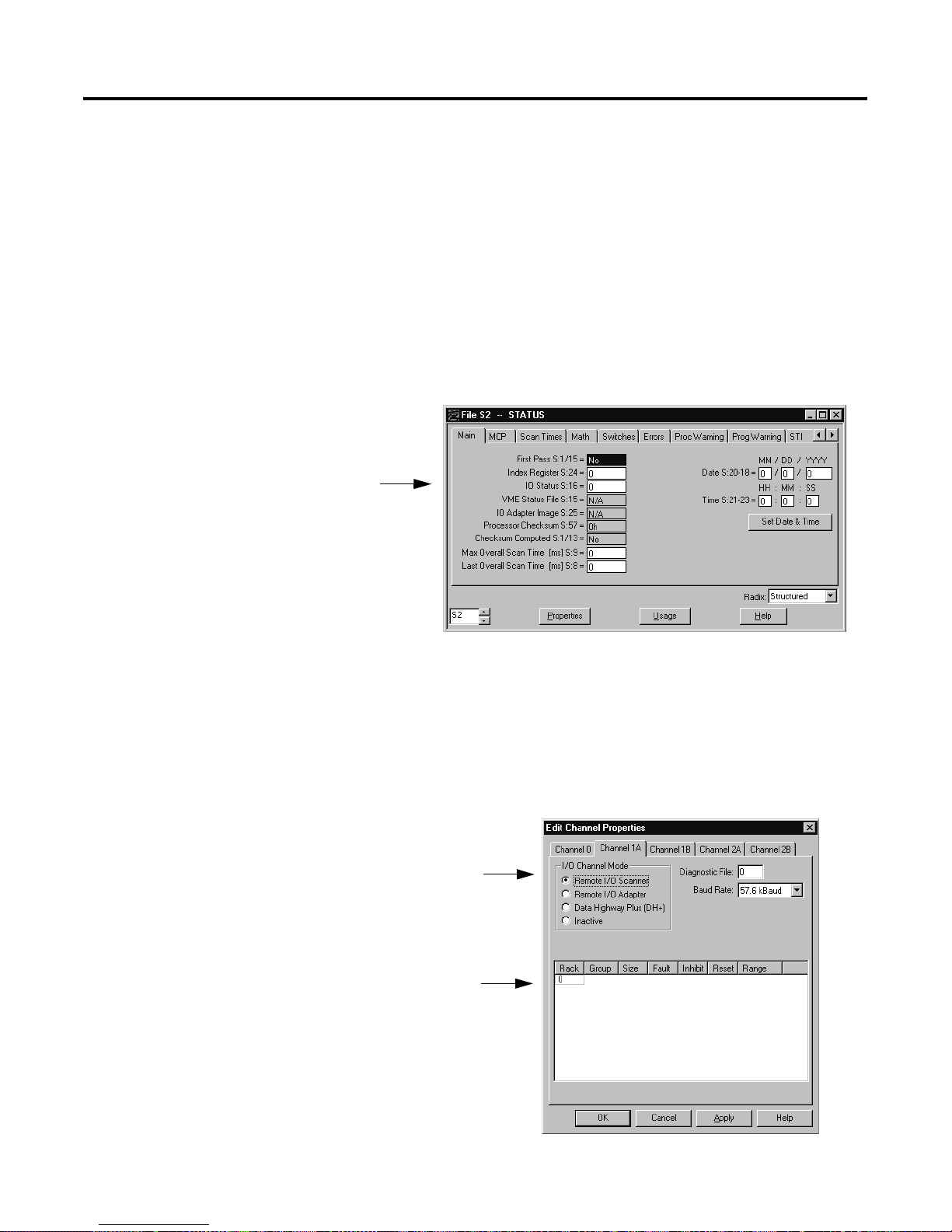
Communicating with Remote I/O 6-7
Define an I/O Status File
The I/O status file stores data for the controller’s I/O rack configuration
tables. The I/O status from each remote I/O rack requires two words. These
two words store the reset, present, inhibit, and fault bits for each rack.
T o define an I/O status file, enter an unused integer file number (9-255) in th e
I/O status file field (S:16) of the controller configuration screen. If you do not
want to use I/O rack configuration tables, enter 0. However, if you want to
use the autoconfiguration option to create your scan list, you must define an
I/O status file. Use the controller configuration screen in your programming
software:
Specify Channel Configuration Information
Use the scanner mode configuration screen in your programming software to
configure a channel for scanner mode.
configure the channel
as a remote I/O scanner
specify the scan list
Publication 1785-UM012D - EN-P - July 2005
Page 80

6-8 Communicating with Remote I/O
ATTENTION
Assign a unique diagnostic file to each channel. Do not
assign a diagnostic file that is the I/O status file you
assigned or any other used integer file. Unpredictable
machine damage can result.
In this Field Define By Doing the Following
Diagnostic file The file containing the channel’s status
information:
• messages received
• messages sent
• messages received with error
• unable to receive
• sent with error
• rack retries
Baud rate The communication rate for the remote
I/O scanner mode link
IMPORTANT
Cursor to the field, type an integer file number (9-999)
Cursor to the field and select the desired rate.Available rates are:
57.6, 115.2, and 230.4 kbps.
Y o u m us t de f ine a dia gnos tics f ile for a c hannel configured
for anything but unused (even if you are not using the
channel) if you want to get status information for that
channel.
Publication 1785-UM012D-EN-P - July 2005
Page 81

Communicating with Remote I/O 6-9
Specify the Scan List
A scan list is a map of the I/O devices being scanned by the scanner channel.
For the channel to communicate with the I/O devices connected to it, you
must create a scan list.
To Do the Following
Create a scan list Make sure the controller is in Remote Program or Program mode.
1.Make sure that you defined an I/O status file on the controller configuration
screen (see page 6-7).
2.Accept any edits made to the channel configuration.
3.Use the autoconfiguration function
If you have errors when you accept edits, clear the scan list and accept edits
again.
If you encounter the error message “Resource not Available,” you have not
defined an I/O status file. Define the I/O status file and try automatic
configuration again.
Insert an entry into the
scan list
Delete an entry for the
scan list
Make sure the controller is in Remote Program, Program, or Remote Run mode.
1.Position the cursor at the place on the scan list where you want to insert an
entry.
2.Insert an entry into the list and enter the appropriate values for the list.
Important: If incorrect information is entered for an entry, the controller will
not display the new configuration when you save edits.
Make sure the controller is in Remote Program, Program, or Remote Run mode.
1.Position the cursor at the place on the scan list where you want to delete an
entry.
2.Delete the entry from the list.
Important: If incorrect information is entered for an entry, the controller will
not display the new configuration when you save edits.
A scan list includes the following:
For this Field: A Scan List Contains
Rack address 1-3 octal (PLC-5/11, -5/20, -5/20E controllers)
1-7 octal (PLC-5/30 controllers)
1-17 octal (PLC-5/40, -5/40L, -5/40E controllers)
1-27 octal (PLC-5/60, -5/60L, -5/80, -5/80E controllers)
If complementary I/O is enabled, a C appears before the complemented rack
address.
Starting group 0, 2, 4, or 6
Rack size 1/2, 1/4, 3/4, or FULL
Range Automatically calculated based on rack address, starting module group and chassis
size.
An asterisk (*) after a range indicates the last valid rack entry.
Publication 1785-UM012D - EN-P - July 2005
Page 82

6-10 Communicating with Remote I/O
TIP
If you need multiple updates to an I/O device during an
I/O scan, you can enter a logical address in the scan list
more than one time. Do not assign the same partial or full
rack address to more than one channel in scanner mode.
Each channel must scan unique partial and/or full rack
addresses.
Keep these limitations in mind when creating/modifying a
scan list:
• The automatic configuration always displays the actual
hardware configur ation, ex cept for racks t hat hav e thei r
global-rack inhibit bit set. In this case, the global-rack
bit overrides the automatic configuration. You must
first clear the global-rack inhibit and then select
autoconfigure.
• Clear global-rack inhibit bits for the channel that scans
the racks that you want to resume scanning. Use the
scanner mode status sc reen in your programmin g
software.
• If you change a channel configuration from adapter or
DH+ mode to scanner mode, use the clear list function
of your programming software to clear the scan list. In
any other instance where you need to clear entries from
the scan list, use the delete-from-l ist func tion to delete
the entries one at a time.
Publication 1785-UM012D-EN-P - July 2005
Page 83
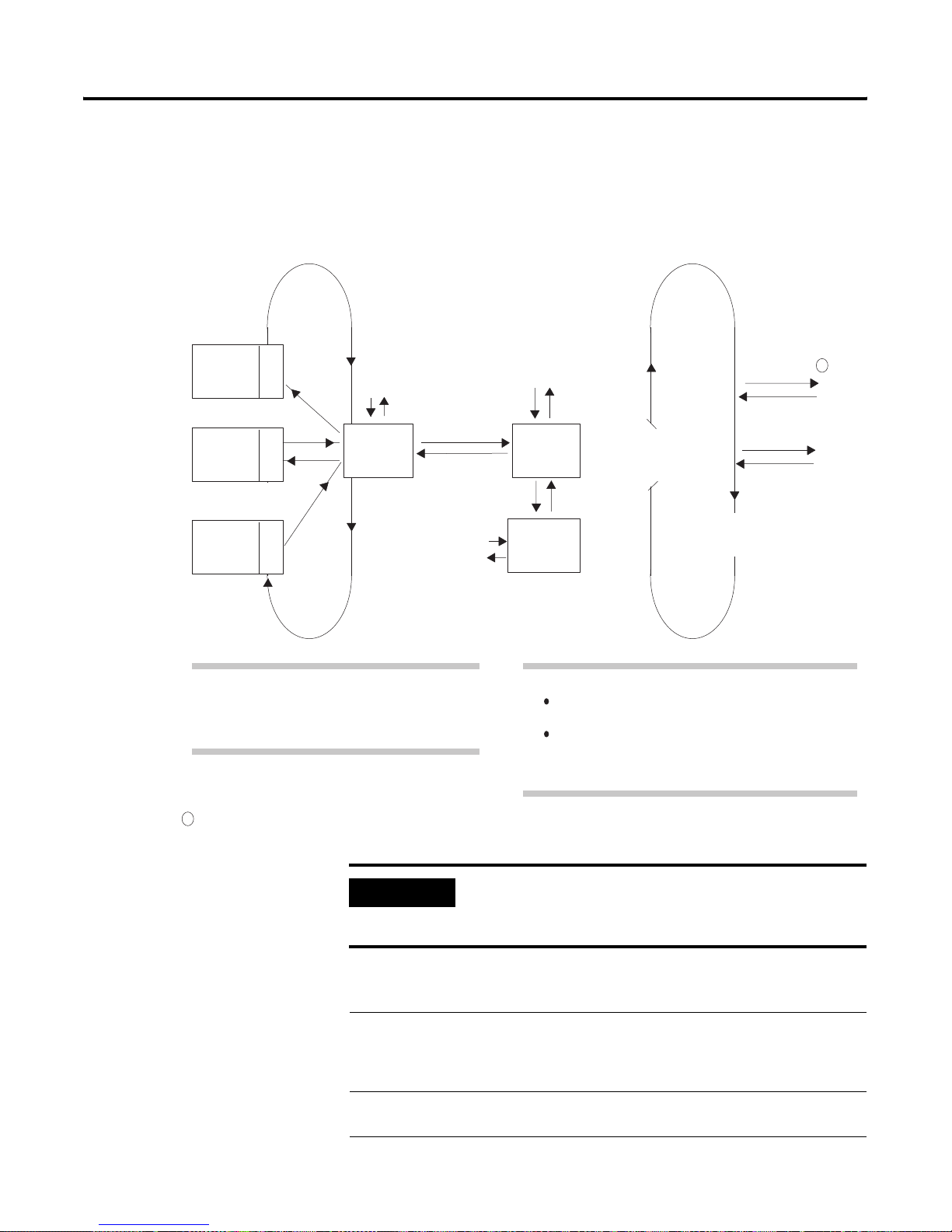
Communicating with Remote I/O 6-11
Communicating to a
Remote I/O Node Adapter
Rack 3
Rack 2
AdapterAdapter Adapter
Rack 1
A scanner channel e xc hanges disc rete data with remote I/O n ode adapters lik e
1771-ASB modules via the remote I/O buffer.
Remote I/O Scan and Program Scan Loops.
Remote I/O Scan Loop
xy
Data Exchange
Remote I/O
Buffer
x
y
ab
I/O Image
Table
ControllerResident
Rack
Update
I/O image
Data
Exchange
Housekeeping
Program Scan Loop
Immediate I/O
a
write outputs
b
read inputs
Logic
Scan
1
IOT (x)
IIN (y)
The remote I/O scan is the time it takes for the
controller to communicate with all of the entries in its
rack scan-list once. The remote I/O scan is
independent of and asynchronous to the program scan.
1
In remote racks, immediate I/O data transfers update the remote I/O buffer.
IMPORTANT
The remote I/O scan for each channel configured for
scanner mode is independent and asynchronous to the
remote I/O scan for any other channel
For the Scanner Channel to Comm unicate with the
1771-ASB Adapter Modules, Do the Following
1.Set the I/O chassis backplane switch for each chassis that
houses an adapter module.
2.Set the switches on the adapter module itself.
3.Connect the remote I/O cable. your controller installation
During housekeeping:
Data exchange between the I/O image table, the
controller-resident rack, and the remote I/O buffer occurs.
The remote I/O buffer is updated.
Remember that the I/O scanner is constantly updating the
remote I/O buffer asynchronously to the program scan.
For More Information,
See:
Appendix E
instructions
Publication 1785-UM012D - EN-P - July 2005
Page 84

6-12 Communicating with Remote I/O
Tro ub lesho otin g Remo te I/O Communi cation Difficulties
Follow these steps to make sure the controller can communicate with devices
on remote I/O links.
1. Put the controller in program mode. Go into the memory map and find
two unused file numbers. The controller will use these files. Do not
create the files, just record which file numbers you will use.
2. Go to the controller status screen and make sure all rack inhibit bits are
zeroed (0).
3. Go to the controller configuration sc reen and assign one of the previous
file numbers to be the I/O status file (see page 6-7).
4. Go to the channel configuration screen for the appr opr ia te channel and
assign the remaining file number (from above) to be the channel
diagnostic file (see page 6-7).
5. Perform an autoconfigure and confirm that all the racks were found and
listed in the I/O scan list.
6. Check all I/O rack retry counters in channel status to make sure there
are no communications problems.
If you follow the above steps and there are still remote I/O communications
problems, it is possible that the I/O status file is corrupt. Try assigning a
brand new I/O status file and repeat the steps above. Also, confirm that the
I/O image tables exist for the racks you are having difficulty communicating
with.
Publication 1785-UM012D-EN-P - July 2005
Page 85

Communicating with Remote I/O 6-13
Transferring Block Data
Remote I/O
In addition to discrete data, the controller can also exchange block data with
remote I/O. Block-transfer instructs the controller to interrupt normal I/O
scanning and transfer as many as 64 words of data to/from a selected I/ O
module. The figure below shows how the scanner-mode controller handles a
block-transfer.
Block-Transferring Data to Controller-Resident Local, Extende d-Local, and
ExtendedLocal
I/O Scan
Local
Rack 4
Local
Racks 2
and 3
Local
Rack 1
3
Adapter
Adapter
Adapter
One transfer per
I/O scan
One transfer per
I/O scan
One transfer per
I/O scan
One transfer per
I/O scan
Q = Queue
A = Active
Buffer
Q
A
Q
A
BT Requests
Q
A
Q
A
BT
Requests
BTR or BTW Data
1
BT Requests
BTR or BTW Data
1
BTR or BTW Data
1
BT Requests
BTR or BTW Data
1
Logic
Scan
Remote I/O
Scan
Rack 7
Rack 6
Rack 5
Remote I/O
2
Adapter
Adapter
Adapter
1
Interrupt from STI or Fault Routine
2
The adapter used in the remote I/O scan is the 1771-ASB.
3
The adapter used in the extended-local I/O scan is the 1771-ALX.
ControllerResident
Rack 0
Multiple
Block Transfers
per I/O Scan
BT
Q
A
I/O Scan
Requests
BTR or BTW Data
1
Program
Scan
15299
Publication 1785-UM012D - EN-P - July 2005
Page 86

6-14 Communicating with Remote I/O
As shown in the previous figure, the controller has the following storage areas
for block-transfers:
Maximum Number of
Active Buffers
Per Remote I/O Channel
PLC-5/60, -5/60L, -5/80, -5/80E 23
PLC-5/40, -5/40L, -5/40E 31
PLC-5/30 39
PLC-5/20, -5/20E 43
PLC-5/11 43
Placing the controller in program
mode, cancels block-tra nsfe rs in
the active buffers and in the
waiting queues.
Storage Area Description
active buffers store initialized block-transfer requests for a channel
The adjacent table lists the maximum active buffers for each
enhanced and Ethernet PLC-5 controller.
The controller places a block-transfer request directly into the
active buffer only if: a buffer is available and no block-transfers to
the slot is in the queue.
waiting queues store block-transfer requests that cannot be placed into the active
buffer because:
all of the channel’s active buffers are being used
the slot addressed by the block-transfer is currently processing a
block-transfer
Once a block-transfer to a slot completes, the controller checks the queue to
see if a block-transfer addressed to the slot is waiting. If one exists, the
controller moves it to the active buffer.
Since a controller can request a block-transfer from ever y slot in a chassis
concurrently, the adapter device chooses the order in which the block- transfers
execute on the chassis. Block-transfer requests are processed differently in
fault routines, selectable timed interrupt routines (STI), and controller input
interrupt routines (PII); see chapters 16, 18, and 19 respectively for more
information.
Publication 1785-UM012D-EN-P - July 2005
Page 87

Communicating with Remote I/O 6-15
Block-Transfer Minor Fault Bits
Minor Fault Description
S:17/0Block-transfer queue full to remote I/O There is a possibility that the PLC-5 controller might temporarily be unable to
initiate multiple consecutive user-programmed block-transfers. For any
block-transfer which temporarily can’t be processes, the PLC-5 controller sets m inor
fault bit S:17/0 and skips that block-transfer instruction. This condition is
self-correcting, but bit S:17/0 remains set until you reset it. You can avoid this
minor fault be separating block-transfer instruction rungs with other rungs.
S:17/1 through S:17/4Queue full - channel xx The PLC-5 controller can process a maximum of 64 remote block-transfers per
channel pair (1A/1B or 2A/2B). This maximum includes:
block-transfers that are currently in the active buffer
initialized block-transfers that are waiting for execution in the holding queue
Once the 64 block-transfer maximum is reached, the following minor fault bits are
set, depending on which channel pair is involved:
Channel pair:Minor fault bits set:
1A/1BS:17/1 and S:17/2
2A/2BS17:3 and S:17/4
The PLC-5 controller won’t initialize any remote block-transfer instruction which
exceeds the 64 maximum. The .EW, .DN, and .ER bits are reset on any
block-transfer which exceeds the 64 maximum. This condition is self-correcting, but
the bits remain set until you reset them.
S:10/7No more command blocks exist This minor fault bit is normally associated with an application programming
problem, but this bit can also be set when using block-transfers if the maximum
number of command blocks available in the PLC-5 controller is exceeded. The
command blocks are used by both the local and remote block-transfers.
Block-Transfers of
Remote I/O Data
PLC-5 type:Maximum number of command blocks:
PLC-5/11, -5/20, -5/30128
PLC-5/40256
PLC-5/60, -5/80384
This condition generally occurs when a program attempts to repeatedly initialize
block-transfers which have not yet completed with a .DN or .ER bit. This condition
is self-correcting, but bit S:10/7 remains set until you reset it.
Block-transfers of I/O data to remote I/O follow these guidelines:
• Block-transfer data exchange and the program scan run independen tly
and concurrently. Once block-transfers are initiated, the controller
performs them asynchronously to the program scan.
• During every remote I/O scan, the Controller performs a maximum of
one block-transfer per entry in the scan list.
Publication 1785-UM012D - EN-P - July 2005
Page 88
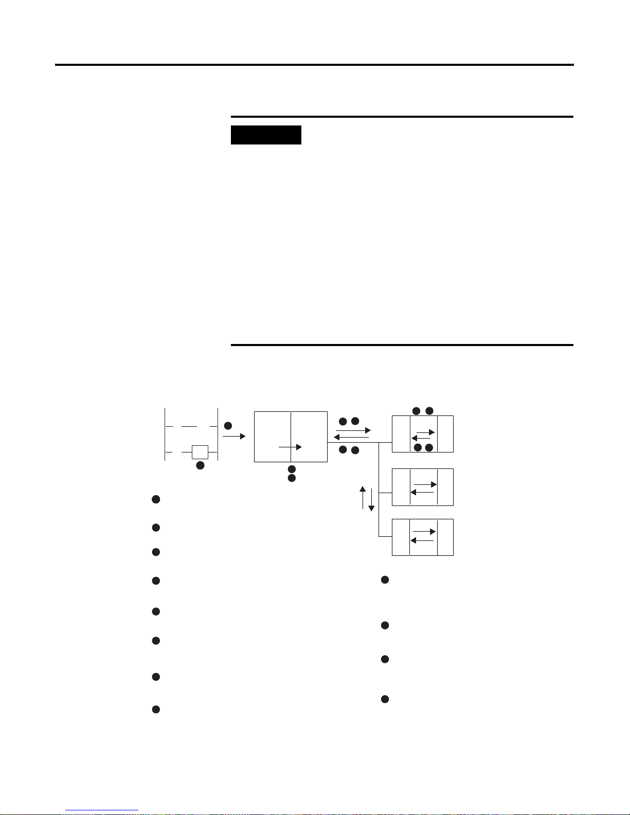
6-16 Communicating with Remote I/O
IMPORTANT
The figure below shows the remote I/O block-transfer sequence.
Scanner within PLC processorLadder Logic
][ ()
][
1
Processor executes a block-transfer instruction.
2
BT
1
BlockTransfer
Requests
If you split remote rack addresses between scanner
channels , block-transfe rs to lower priority scanner cha nnels
do not function properly. Scanner channels have priority
according to the following order: 1A, 1B, 2A, then 2B.
For example: if you configure channels 1B and 2A as
remote scanners and split rack #2 between them,
block-transfers to channel1B (the higher priority channel)
will be completed, but block-transfers to the second half of
rack #2 (2A, the lower priority channel) will not be
completed.
Although splitting remote I/O racks across scanner
channels does not affect discrete transfers, I/O status bits
such as Fault and Present may not indicate the correct
status.
Remote I/O
10
5
Adapter
6
AdapterAdapter
BT
11
BT
Discrete
I/O
3
8
4
9
7
12
2
Processor sends the block-transfer request to
its I/O scanner.
3
Scanner places module control byte (MCB) into the
discrete output image table.
4
Scanner sends MCB as part of the discrete I/O
update to the adapter.
5
The adapter module sends the block-transfer request
to the block-transfer module.
6
The block-transfer module returns a module status
byte (MSB) to the adapter.
7
MSB returned to the scanner in addition to the
discrete I/O by the adapter.
8
The scanner forms a block-transfer packet.
Publication 1785-UM012D-EN-P - July 2005
BT
The scanner sends the block-transfer packet to
9
the adapter for the block-transfer module
(the packet includes data if it is a block-transfer write).
The adapter passes the block-transfer packet to
10
the block-transfer module.
The block-transfer module sends status to the
11
adapter (will also send data if it is a blocktransfer read).
The adapter passes status to the I/O scanner;
12
if the request is a block-transfer read, adapter
sends data.
Page 89

Communicating with Remote I/O 6-17
Block-Transfer Sequence
with Status Bits
Start
ladder logic
Detects that a rung containing a
block-transfer is enabled and sets the
enable .EN bit and resets the .ST, .DN, .ER,
and .EW status bits.
The processor sends the block-transfer
request to the I/O scanner, sets the .EW bit,
and resumes the program scan.
The following figure describes the different states of the block-transfer
status bits.
Executes block-transfer
asynchronously to the
program scan
I/O scanner
A
Does this slot address
have a BT in process?
no
Is an active buffer available?
yes
Is the request a BTW?
yes
The scanner accesses the BTW file in the data
table and copies the data to the active buffer.
yes
The scanner place the request
in the waiting queue.
no
Transfers the block-transfer
request to/from the I/O chassis.
no
The scanner sets the .ST status
bit and starts the watchdog timer.
Does the module respond?
yes
see page 6-18
B
no
C
see page
6-19
Publication 1785-UM012D - EN-P - July 2005
Page 90
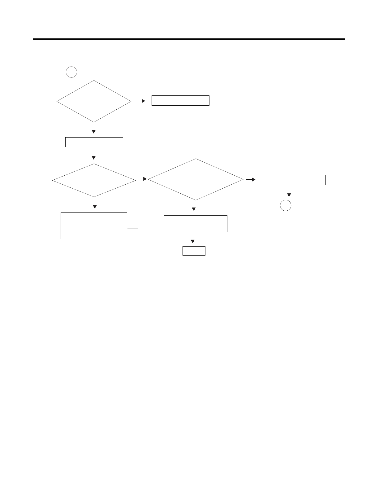
6-18 Communicating with Remote I/O
B
Did the block-transfer
complete without errors?
yes
Sets the done .DN bit (13).
Was the block-transfer
a BTR?
yes
Copies data from the active
buffer to the block-transfer file
in the data table.
no
Sets the error .ER bit (12).
no
Is the block-transfer
continuous? (the .CO bit is set.)
no
Frees up the active buffer
for the next request
go to
Start
see page
6-17
yes
Re-initializes the block-transfer.
A
go to
see page
6-17
Publication 1785-UM012D-EN-P - July 2005
Page 91

Communicating with Remote I/O 6-19
C
Is the block-transfer for a
local I/O module?
yes
Sets the no response .NR bit (09).
Is the timeout .TO bit (08) set?
yes
no
Block-transfer is for a module in a remote rack.
Is the timeout .TO bit (08) set?
Continues to request the block-transfer for 0-1 s
before setting the .ER bit (12).
no
Re-initializes the request until
the watchdog timer expires (4 s).
no
Continues to request the
block-transfer until the watchdog
timer expires (4 s).
yes
Retries request once more before setting the .ER bit (12)
Block-Transfer
Programming
Considerations
For a list of block-transfer error codes, see the PLC-5 Programming Software
Instruction Set Reference, publication 1785-6.1.
Read this section for information about general programming considerations
and considerations for controller-resident local racks.
General Considerations
The following are general programm ing considerations when you are
block-transferring I/O data.
Publication 1785-UM012D - EN-P - July 2005
Page 92

6-20 Communicating with Remote I/O
• When performing block-transfers (controller-resident local or remote
I/O) in any PLC-5 controller, clear the output image table
corresponding to the block-transfer module rack location before
changing to run mode. If you do not clear the output image table, then
you encounter block-transfer errors because unsolicited block-transfers
are being sent to the block-transfer module (i.e., if a block-transfer
module is installed in rack 2, group 4, clear output word O:024 to 0; do
not use the word for storing data).
• If you use remote block-transfer instructions and have the timeout bit
(.TO) set to 1, then the controller disables the 4-second timer and
continues to request the block-transfer for 0-1 seconds before setting
the error (.ER) bit.
• A PLC-5 controller with at least one channel configured as an adapter
could incur a non-recoverable fault when you switch it from run to
program mode.
To avoid this possibility, program the scanner to request only two or three
block-transfers from the PLC-5 adapter at one time by conditioning the
block-transfer instructions with the done/error bits.
For Controller-Resident Local Racks
The following are programming considerations when you are
block-transferring data in a controller-resident local rack.
• Within the controller-resident local rack, limit the number of
continuous-read block- tra n sfers to 16 transfers of 4 words each or 8
transfers of 64 words each. If you attempt to exceed this block-transfer
limit, a checksum error (error code -5) occurs.
• Block-transfer instructions to any of the following modules residing in
the controller-resident local rack result in frequent checksum errors.
– 1771-OFE1, -OFE2, and -OFE3 modules; all versions prior to series
B, revision B
– 2803-VIM module, all versions prior to series B, revision A
– IMC-120, all versions
• To eliminate the checksum errors, replace your modules with the current
series and revision. If replacement is not possible:
1. Go to the controller configuration screen in your programming
software.
Publication 1785-UM012D-EN-P - July 2005
2. With the controll er in program mode , se t user cont rol bit 4 (S:26/4) to 1
(the local block-transfer compatibility bit).
3. Change the controller mode from program to run.
Page 93
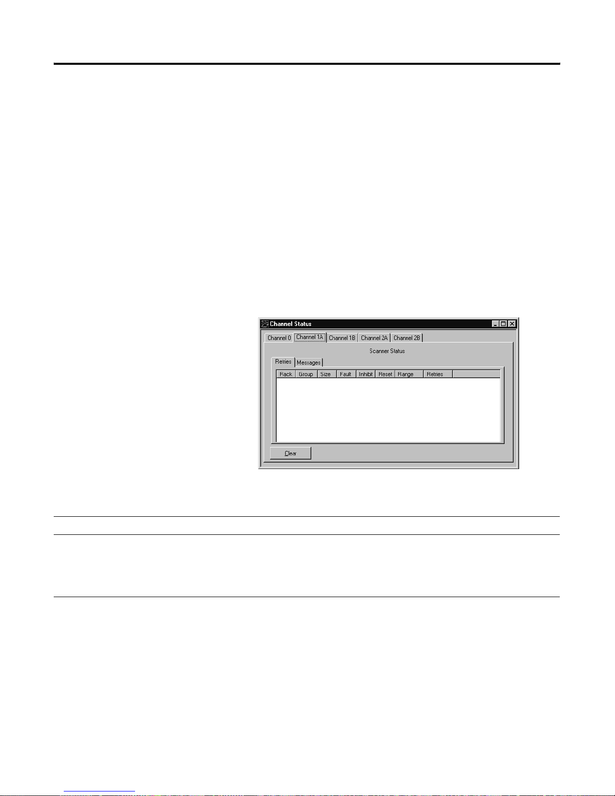
Communicating with Remote I/O 6-21
• Do not program IIN or IOT instructions to a module in the same
physical module group as a BT module unless you know a block-transfer
is not in progress. If you must do this, then use an XIO instruction to
examine the .EN bit of the block-transfer instruction to condition the
IIN and IOT.
Monitoring Remote I/O
Scanner Channels
To monitor channels configured as a scanner, use the scanner mode status
screen in your programming software. This screen displays the data in the
diagnostic file you defined on the scanner mode configuration screen (page
6-7).
Monitoring transmission retries
Status Field Location Description
Retries Tab
Retry word 5
etc.
word 69
Displays the number of retries for the corresponding rack entry.
Entry 1
etc.
Entry 64
Publication 1785-UM012D - EN-P - July 2005
Page 94

6-22 Communicating with Remote I/O
Status Field Location Description
Rack Address This field indicates the rack number of the remote racks being scanned by the scanner channel:
can only scan rack 3 (PLC-5/11 controller)
1-3 octal (PLC-5/20, -5/20E controller)
1-7 octal (PLC-5/30 controllers)
1-17 octal (PLC-5/40, -5/40L, 5/40E controllers)
1-27 octal (PLC-5/60, -5/60L, -5/80, -5/80E controllers)
If complementary I/O is enabled (on the scanner mode configuration screen), the complement of
a rack is identified with a C to the left of the rack address column on the status screen.
Starting Group This field indicates the first I/O module group in the rack that the controller scans.
Rack Size This field displays the portion of the I/O rack addressed by each chassis. Configurations can be
1/4, 1/2, 3/4, or FULL as long as the total sum of the rack does not exceed 8 I/O groups.
Range This field displays the rack address and module groups being scanned for a rack in the scan list.
An asterisk (*) after a range indicates that it is the last valid rack entry.
Fault An F displayed in this field indicates that the corresponding chassis is faulted. When a fault
indicator appears, the system sets the associated fault bit in the global rack fault status on the
controller status screen in your programming software.
When the global rack fault bit is set, all configuration information starting at the faulted quarter
is lost. When a rack faults, F is displayed. If both the fault and inhibit bits are set for a rack, no
rack exists at that I/O group.
Inhibit Inhibit a rack by cursoring to the Inhibit field of the rack you want to inhibit and enter 1
When a chassis is inhibited the controller stops scanning it. You can inhibit an entire rack by
setting the global rack-inhibit bit for that rack on the controller status screen. All chassis within
that rack are inhibited, and an I appears in the
Inhibit field, indicating the rack was globally
inhibited.
Reset Reset a rack by cursoring to the Reset field of the rack you want to reset and type 1
When a chassis is reset, the controller turns of f the outputs of the chassis regardless of the
last-state switch setting. You can reset an entire rack by setting the global rack-reset bit on the
controller status screen. All chassis within that rack are reset, and an R appears in the
Reset
field indicating the rack was globally reset.
Retry This field displays the number of times the rack was re-scanned.
Publication 1785-UM012D-EN-P - July 2005
Page 95
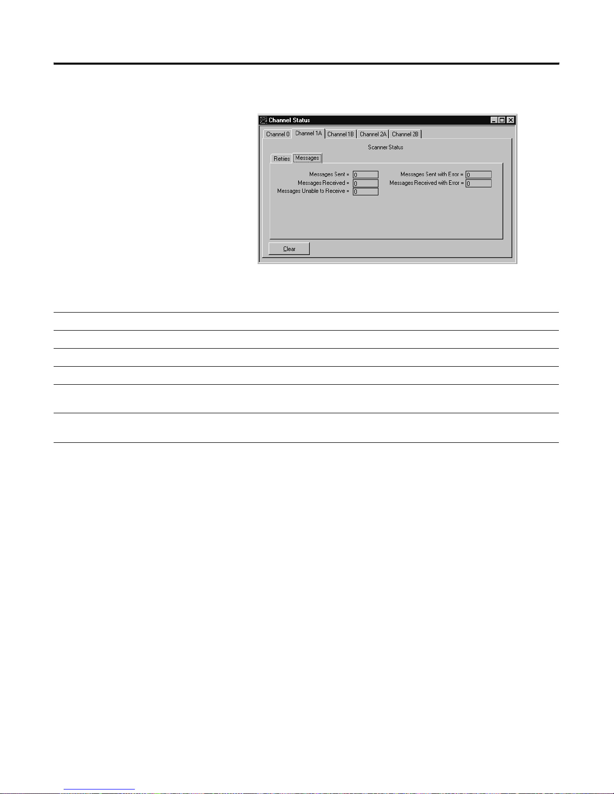
Monitoring messages
Status Field Location Description
Messages Tab (Messages = SDA messages + SDN messages)
Messages sent word 1 Displays the number of messages sent by the channel.
Communicating with Remote I/O 6-23
Messages sent with error word 3 Displays the number of messages containing errors sent by the channel.
Messages received word 0 Displays the number of error-free messages received by the channel.
Messages received with
word2 Displays the number of messages containing errors received by the channel (such as bad CRC).
error
Messages unable to receive word 4 Displays the number of messages received with protocol-related problems (such as a bad
block-transfer status byte with both read and write bits set).
Publication 1785-UM012D - EN-P - July 2005
Page 96

6-24 Communicating with Remote I/O
Addressing the I/O
Status Fil e
During program execution you can address words and fault bits within the
I/O status file. The following figure shows the arrangement of the words in
the I/O status file for a given remote or extended local I/O rack. The example
status file used for the figures in this section is integer file 15.
Defined I/O status file
Word in integer file
N15:0
N15:1
N15:14
N15:15
N15:30
N15:31
N15:46
N15:47
rack 0
rack 3
rack 7
rack 17
rack 27
(Maximum for PLC-5/11, -5/20, and -5/20E)
(Maximum for PLC-5/30 processors)
(Maximum for PLC-5/40, -5/40L, and -5/40E processors)
(Maximum for PLC-5/60, -5/60L,
-5/80 and -5/80E processors)
The first word for a rack contains present and fault bits, the second word
contains reset and in hibit bits. The following figure shows pr e sent , fa ult , r eset,
and inhibit bit layouts for rack 7 in the I/O status file.
IMPORTANT
Setting inhibit bits in the I/O status file does not update
inhibit bits in the controller status file.
Publication 1785-UM012D-EN-P - July 2005
Page 97

Communicating with Remote I/O 6-25
Bit Layout Diagrams for the First Word Allotted to a Remote I/O Rack or an
Extended-Local I/O Rack
N15:14
Not Used
Fault BitsPresent Bits
00010203040506070809101112131415
Not Used
This Bit Corresponds to
Fault Bits
00 first 1/4 rack
starting I/O group 0
01 second 1/4 rack
starting I/O group 2
02 third 1/4 rack
starting I/O group 4
03 fourth1/4 rack
starting I/O group 6
Present Bits
08 first 1/4 rack
starting I/O group 0
09 second 1/4 rack
starting I/O group 2
10 third 1/4 rack
starting I/O group 4
11 fourth1/4 rack
starting I/O group 6
Publication 1785-UM012D - EN-P - July 2005
Page 98

6-26 Communicating with Remote I/O
Bit Layout Diagrams for the Second Word Allotted to a Remote I/O Rack or an
Extended Local I/O Rack
N15:15
Not Used
Reset Bits
This Bit: Corresponds to:
Inhibit Bits
00 first 1/4 rack
starting I/O group 0
01 second 1/4 rack
starting I/O group 2
02 third 1/4 rack
starting I/O group 4
03 fourth1/4 rack
starting I/O group 6
Reset Bits
Inhibit Bits
00010203040506070809101112131415
Not Used
08 first 1/4 rack
09 second 1/4 rack
10 third 1/4 rack
11 fourth1/4 rack
ATTENTION
starting I/O group 0
starting I/O group 2
starting I/O group 4
starting I/O group 6
When you use a ladder program or the software to
inhibit and reset an I/O rack, you must set or clear the
reset and inhibit bits that correspond to each quarter
rack in a given chassis . Failure to set all the appropriate
bits could cause unpredictable operation due to
scanning only part of the I/O chassis.
Publication 1785-UM012D-EN-P - July 2005
Page 99

Using This Chapter
Communicating with a PLC-5
Adapter Channel
For Information About: Go to Page:
Configuring communication to a PLC-5 adapter channel 7-2
Programming discrete transfers 7-10
Programming block-data transfers 7-10
Monitoring the status of the adapter channel 7-17
Monitoring the status of the supervisory controller 7-18
Chapter
7
Monitoring remote I/O adapter channels 7-19
This chapter explains how to configure the controller to communicate with an
adapter channel:
1. Select which channel to configure as an adapter.
2. Define a diagnostic file.
3. Use a unique, unused integer file.
4. Define the rack address, starting group and rack size.
5. The default rack address is rack 3.
6. Define the discrete transfer files (enter as decimal numbers).
7. The input source is where the supervisory controller’s output discrete
bits go (default is 001:024 - the decimal representation of rack 3). The
output source is where the supervisory controller’s input bits go (default
is 000:024).
8. Create the necessary block-transfer control files (one BTR and one
BTW).
1 Publication 1785-UM012D - EN-P - July 2005
9. Configure the block-transfers so the supervisory controller knows
where to address block-transfers.
Page 100

7-2 Communicating with a PLC-5 Adapter Channel
Configuring
Communication to a
PLC-5 Adapter Channel
Supervisory Processor in Scanner Mode
a
write
outputs
b
read
inputs
Update
I/O image
Housekeeping
Because a PLC-5 controller adapter channel is more intelligent than a
1771-ASB module, data communication and configuration tasks are handled
differently for adapter channels.
The supervisory controller or scanner channel and the adapte r-mode
controller channel automatically transfer discrete data and status between
themselves via the supervisory controller’s remote I/O scan.
PLC-5 Processor Channel in Adapter Mode
Discrete Transfer
Configuration Files
Data Exchange
Remote I/O
Buffer
I/O Image
Table
Update
I/O image
Housekeeping
Logic
Scan
a
write outputs
b
read inputs
Remote I/O
Buffer
I/O Image
Table
Discrete
Data and
Status Bit
Exchange
ab
Remote I/O Scan Program Scan
During each remote I/O scan, the supervisory processor transfers
2, 4, 6, or 8 words*depending on whether the adapter-mode
processor is configured as a 1/4, 1/2, 3/4, or full rack.
Discrete data and block-transfer status bits are transferred between a remote
I/O scanner’s I/O image table and an adapter channel via the adapter
channel’s discrete transfer configuration files , which you define on the adapter
channel configuration screen.
For the Scanner Channel to Comm unicate with a PLC-5 Contro l ler Adapter
Channel, Do the Following
1.Define the communication rate, its address, and rack size (number of words to transfer). page 7-3
2.Define the discrete transfer configuration files, which are the files from which the
adapter controller channel gets the data sent by the supervisory controller and puts data
into for the supervisory controller.
3.If you plan to block-transfer data to the adapter channel, define the block-transfer files
and configure the block-transfers.
ab
The adapter-mode processor transfers 2, 4, 6, or 8 words*depending
on whether it is configured as a 1/4, 1/2, 3/4, or full rack.
For More Information, See
page 7-5
page 7-10
4.Connect the remote I/O cable. your controller installation
Publication 1785-UM012D-EN-P - July 2005
instructions
 Loading...