

Page 1

User Manual
Original Instructions
Stratix Managed Switches
Stratix 5400 Switches (1783-HMS)
Stratix 5410 Switches (1783-IMS)
Stratix 5700 Switches (1783-BMS)
ArmorStratix 5700 Switches (1783-ZMS)
Stratix 8000 and 8300 Switches (1783-MS, 1783-RMS, 1783-MX)
Page 2
Important User Information
Read this document and the documents listed in the additional resources section about installation, configuration, and
operation of this equipment before you install, configure, operate, or maintain this product. Users are required to
familiarize themselves with installation and wiring instructions in addition to requirements of all applicable codes, laws,
and standards.
Activities including installation, adjustments, putting into service, use, assembly, disassembly, and maintenance are
required to be carried out by suitably trained personnel in accordance with applicable code of practice.
If this equipment is used in a manner not specified by the manufacturer, the protection provided by the equipment may
be impaired.
In no event will Rockwell Automation, Inc. be responsible or liable for indirect or consequential damages resulting from
the use or application of this equipment.
The examples and diagrams in this manual are included solely for illustrative purposes. Because of the many variables and
requirements associated with any particular installation, Rockwell Automation, Inc. cannot assume responsibility or
liability for actual use based on the examples and diagrams.
No patent liability is assumed by Rockwell Automation, Inc. with respect to use of information, circuits, equipment, or
software described in this manual.
Reproduction of the contents of this manual, in whole or in part, without written permission of Rockwell Automation,
Inc., is prohibited
Throughout this manual, when necessary, we use notes to make you aware of safety considerations.
WARNING: Identifies information about practices or circumstances that can cause an explosion in a hazardous
environment, which may lead to personal injury or death, property damage, or economic loss.
ATTENTION: Identifies information about practices or circumstances that can lead to personal injury or death, property
damage, or economic loss. Attentions help you identify a hazard, avoid a hazard, and recognize the consequence.
IMPORTANT Identifies information that is critical for successful application and understanding of the product.
Labels may also be on or inside the equipment to provide specific precautions.
SHOCK HAZARD: Labels may be on or inside the equipment, for example, a drive or motor, to alert people that dangerous
voltage may be present.
BURN HAZARD: Labels may be on or inside the equipment, for example, a drive or motor, to alert people that surfaces may
reach dangerous temperatures.
ARC FLASH HAZARD: Labels may be on or inside the equipment, for example, a motor control center, to alert people to
potential Arc Flash. Arc Flash will cause severe injury or death. Wear proper Personal Protective Equipment (PPE). Follow ALL
Regulatory requirements for safe work practices and for Personal Protective Equipment (PPE).
Page 3

Table of Contents
Preface . . . . . . . . . . . . . . . . . . . . . . . . . . . . . . . . . . . . . . . . . . . . . . . . . . . . . . 13
Access Product Release Notes . . . . . . . . . . . . . . . . . . . . . . . . . . . . . . . . . . 13
Additional Resources . . . . . . . . . . . . . . . . . . . . . . . . . . . . . . . . . . . . . . . . . . 13
Summary of Changes . . . . . . . . . . . . . . . . . . . . . . . . . . . . . . . . . . . . . . . . . . 15
Chapter 1
About the Switches EtherNet/IP CIP Interface. . . . . . . . . . . . . . . . . . . . . . . . . . . . . . . . . . . . . 19
CIP Network Connections. . . . . . . . . . . . . . . . . . . . . . . . . . . . . . . . . 19
EtherNet/IP QuickConnect Technology. . . . . . . . . . . . . . . . . . . . 19
Lite Versus Full Firmware Features (Stratix 5700 Switches) . . . . . . . 20
Software Features . . . . . . . . . . . . . . . . . . . . . . . . . . . . . . . . . . . . . . . . . . . . . 21
Hardware Features . . . . . . . . . . . . . . . . . . . . . . . . . . . . . . . . . . . . . . . . . . . . 22
Memory Allocation. . . . . . . . . . . . . . . . . . . . . . . . . . . . . . . . . . . . . . . . . . . . 25
Stratix 5400 Templates . . . . . . . . . . . . . . . . . . . . . . . . . . . . . . . . . . . . 25
Stratix 5410 Templates . . . . . . . . . . . . . . . . . . . . . . . . . . . . . . . . . . . . 26
Stratix 5700 and ArmorStratix 5700 Templates . . . . . . . . . . . . . . 27
Stratix 8000 and 8300 Templates . . . . . . . . . . . . . . . . . . . . . . . . . . . 28
Chapter 2
Get Started Express Setup Overview. . . . . . . . . . . . . . . . . . . . . . . . . . . . . . . . . . . . . . . . 30
Express Setup Requirements. . . . . . . . . . . . . . . . . . . . . . . . . . . . . . . . 30
Express Setup Button . . . . . . . . . . . . . . . . . . . . . . . . . . . . . . . . . . . . . . 32
Multi-mode Express Setup . . . . . . . . . . . . . . . . . . . . . . . . . . . . . . . . . . . . . 34
Run Multi-mode Express Setup in Short Press Mode . . . . . . . . . 35
Run Multi-mode Express Setup in Medium Press Mode . . . . . . 36
Run Multi-mode Express Setup in Long Press Mode. . . . . . . . . . 37
Single-mode Express Setup . . . . . . . . . . . . . . . . . . . . . . . . . . . . . . . . . . . . . 38
Configure Network Settings via Device Manager. . . . . . . . . . . . . . . . . 39
Configure Network Settings via the Logix Designer Application . . 42
Default Global Macro . . . . . . . . . . . . . . . . . . . . . . . . . . . . . . . . . . . . . . . . . 44
RSLinx Software and Network Who Support. . . . . . . . . . . . . . . . . . . . 44
Electronic Data Sheet (EDS) Files. . . . . . . . . . . . . . . . . . . . . . . . . . . 44
Data Accessible with CIP . . . . . . . . . . . . . . . . . . . . . . . . . . . . . . . . . . 45
Configuration via Device Manager. . . . . . . . . . . . . . . . . . . . . . . . . . . . . . 47
Access Device Manager . . . . . . . . . . . . . . . . . . . . . . . . . . . . . . . . . . . . 48
Configure Port Settings . . . . . . . . . . . . . . . . . . . . . . . . . . . . . . . . . . . . 51
Configuration via the Studio 5000 Environment. . . . . . . . . . . . . . . . . 53
General Properties. . . . . . . . . . . . . . . . . . . . . . . . . . . . . . . . . . . . . . . . . 55
Connection Properties . . . . . . . . . . . . . . . . . . . . . . . . . . . . . . . . . . . . . 57
Switch Configuration. . . . . . . . . . . . . . . . . . . . . . . . . . . . . . . . . . . . . . 58
Port Configuration . . . . . . . . . . . . . . . . . . . . . . . . . . . . . . . . . . . . . . . . 59
User Administration via Device Manager. . . . . . . . . . . . . . . . . . . . . . . . 61
Configuration Files. . . . . . . . . . . . . . . . . . . . . . . . . . . . . . . . . . . . . . . . . . . . 62
Manage Configuration Files via Device Manager . . . . . . . . . . . . . 62
Manage Configuration Files via the Logix Designer Application . . 63
Rockwell Automation Publication 1783-UM007G-EN-P - February 2017 3
Page 4

Table of Contents
Secure Digital (SD) Card . . . . . . . . . . . . . . . . . . . . . . . . . . . . . . . . . . . . . . 64
Synchronize the SD Card via Device Manager . . . . . . . . . . . . . . . 65
Synchronize the SD Card via the Logix Designer Application . 67
CompactFlash Memory Card (Stratix 8000/8300 Switches) . . . . . . 68
Firmware Updates. . . . . . . . . . . . . . . . . . . . . . . . . . . . . . . . . . . . . . . . . . . . . 68
Cisco Network Assistant. . . . . . . . . . . . . . . . . . . . . . . . . . . . . . . . . . . . . . . 69
Command-line Interface. . . . . . . . . . . . . . . . . . . . . . . . . . . . . . . . . . . . . . . 70
Chapter 3
Install Stratix 5400 Switches Specifications . . . . . . . . . . . . . . . . . . . . . . . . . . . . . . . . . . . . . . . . . . . . . . . . . 75
Overview . . . . . . . . . . . . . . . . . . . . . . . . . . . . . . . . . . . . . . . . . . . . . . . . . . . . . 75
Parts List and Required Tools . . . . . . . . . . . . . . . . . . . . . . . . . . . . . . . . . . 76
Install or Remove the SD Card . . . . . . . . . . . . . . . . . . . . . . . . . . . . . . . . . 78
Verify Switch Operation . . . . . . . . . . . . . . . . . . . . . . . . . . . . . . . . . . . . . . . 79
Mount the Switch on a DIN Rail . . . . . . . . . . . . . . . . . . . . . . . . . . . . . . . 80
Remove the Switch from the DIN Rail . . . . . . . . . . . . . . . . . . . . . . . . . . 81
Ground the Switch . . . . . . . . . . . . . . . . . . . . . . . . . . . . . . . . . . . . . . . . . . . . 81
Wire the Switch DC Power Source . . . . . . . . . . . . . . . . . . . . . . . . . . . . . 83
Attach the Switch Power Connectors . . . . . . . . . . . . . . . . . . . . . . . . . . . 85
Install an SFP Module . . . . . . . . . . . . . . . . . . . . . . . . . . . . . . . . . . . . . . . . . 87
Remove an SFP Module from an SFP Slot . . . . . . . . . . . . . . . . . . . . . . 89
Wire the External Alarms . . . . . . . . . . . . . . . . . . . . . . . . . . . . . . . . . . 90
Attach the Alarm Relay Connector to the Switch . . . . . . . . . . . . . . . . 93
Connect to 10/100 and 10/100/1000 Ports . . . . . . . . . . . . . . . . . . . . . 93
Connect to 10BASE-T, 100BASE-TX, or 1000BASE-T Ports . . . . 94
Connect to PoE Ports . . . . . . . . . . . . . . . . . . . . . . . . . . . . . . . . . . . . . . . . . 95
Connect to SFP Module Ports. . . . . . . . . . . . . . . . . . . . . . . . . . . . . . . . . . 95
Connect to a Dual-purpose Port. . . . . . . . . . . . . . . . . . . . . . . . . . . . . . . . 96
Chapter 4
Install Stratix 5410 Switches Switch Specifications . . . . . . . . . . . . . . . . . . . . . . . . . . . . . . . . . . . . . . . . . 101
Power Supply Specifications. . . . . . . . . . . . . . . . . . . . . . . . . . . . . . . . . . . 101
Overview . . . . . . . . . . . . . . . . . . . . . . . . . . . . . . . . . . . . . . . . . . . . . . . . . . . . 102
Parts List and Required Tools . . . . . . . . . . . . . . . . . . . . . . . . . . . . . . . . . 103
Install or Remove the SD Card . . . . . . . . . . . . . . . . . . . . . . . . . . . . . . . . 105
Verify Switch Operation . . . . . . . . . . . . . . . . . . . . . . . . . . . . . . . . . . . . . . 107
Mount the Switch on a Rack . . . . . . . . . . . . . . . . . . . . . . . . . . . . . . . . . . 107
Attach Brackets . . . . . . . . . . . . . . . . . . . . . . . . . . . . . . . . . . . . . . . . . . 108
Mount the Switch . . . . . . . . . . . . . . . . . . . . . . . . . . . . . . . . . . . . . . . . 110
Mount the Switch on a Wall . . . . . . . . . . . . . . . . . . . . . . . . . . . . . . . . . . 111
Attach the Brackets . . . . . . . . . . . . . . . . . . . . . . . . . . . . . . . . . . . . . . . 111
Mount the Switch . . . . . . . . . . . . . . . . . . . . . . . . . . . . . . . . . . . . . . . . 113
Ground the Switch . . . . . . . . . . . . . . . . . . . . . . . . . . . . . . . . . . . . . . . . . . . 114
Install a Power Supply Module in the Switch . . . . . . . . . . . . . . . . . . . 115
Wire the Power Source . . . . . . . . . . . . . . . . . . . . . . . . . . . . . . . . . . . . . . . 116
Remove a Power Supply Module from the Switch . . . . . . . . . . . . . . . 120
4 Rockwell Automation Publication 1783-UM007G-EN-P - February 2017
Page 5

Table of Contents
Install an SFP Module . . . . . . . . . . . . . . . . . . . . . . . . . . . . . . . . . . . . . . . . 120
Remove an SFP Module from an SFP Slot . . . . . . . . . . . . . . . . . . . . . . 122
Wire the External Alarms . . . . . . . . . . . . . . . . . . . . . . . . . . . . . . . . . . . . . 123
Attach the Alarm Relay Connector to the Switch . . . . . . . . . . . . . . . 124
Connect to 10/100/1000 Ethernet, PoE/PoE+ Ports . . . . . . . . . . . 124
Connect to SFP/SFP+ Ports . . . . . . . . . . . . . . . . . . . . . . . . . . . . . . . . . . 126
Chapter 5
Install Stratix 5700 Switches Specifications . . . . . . . . . . . . . . . . . . . . . . . . . . . . . . . . . . . . . . . . . . . . . . . . 130
Overview . . . . . . . . . . . . . . . . . . . . . . . . . . . . . . . . . . . . . . . . . . . . . . . . . . . . 130
Parts List and Required Tools . . . . . . . . . . . . . . . . . . . . . . . . . . . . . . . . . 132
Install or Remove the SD Card . . . . . . . . . . . . . . . . . . . . . . . . . . . . . . . . 133
Verify Switch Operation . . . . . . . . . . . . . . . . . . . . . . . . . . . . . . . . . . . . . . 134
Mount the Switch on a DIN Rail . . . . . . . . . . . . . . . . . . . . . . . . . . . . . . 135
Remove the Switch from the DIN Rail . . . . . . . . . . . . . . . . . . . . . . . . . 137
Ground the Switch . . . . . . . . . . . . . . . . . . . . . . . . . . . . . . . . . . . . . . . . . . . 137
Wire the Switch DC Power Source . . . . . . . . . . . . . . . . . . . . . . . . . . . . 139
Attach the Switch Power Connectors . . . . . . . . . . . . . . . . . . . . . . . . . . 143
Wire the Power over Ethernet DC Power Source . . . . . . . . . . . . . . . 144
Attach the PoE Power Connector . . . . . . . . . . . . . . . . . . . . . . . . . . . . . 145
Install an SFP Module . . . . . . . . . . . . . . . . . . . . . . . . . . . . . . . . . . . . . . . . 146
Remove an SFP Module from an SFP Slot . . . . . . . . . . . . . . . . . . . . . . 148
Wire the External Alarms . . . . . . . . . . . . . . . . . . . . . . . . . . . . . . . . . 149
Attach the Alarm Relay Connector to the Switch . . . . . . . . . . . . . . . 152
Connect to 10/100 and 10/100/1000 Ports . . . . . . . . . . . . . . . . . . . . 152
Connect to 10BASE-T, 100BASE-TX, or 1000BASE-T Ports . . . 153
Connect to PoE Ports . . . . . . . . . . . . . . . . . . . . . . . . . . . . . . . . . . . . . . . . 154
Connect to SFP Module Ports. . . . . . . . . . . . . . . . . . . . . . . . . . . . . . . . . 154
Connect to a Dual-purpose Port. . . . . . . . . . . . . . . . . . . . . . . . . . . . . . . 155
Install Stratix 8000 and
8300 Switches
Chapter 6
Specifications . . . . . . . . . . . . . . . . . . . . . . . . . . . . . . . . . . . . . . . . . . . . . . . . 159
Overview . . . . . . . . . . . . . . . . . . . . . . . . . . . . . . . . . . . . . . . . . . . . . . . . . . . . 160
Parts List and Required Tools . . . . . . . . . . . . . . . . . . . . . . . . . . . . . . . . . 162
Attach Expansion Modules. . . . . . . . . . . . . . . . . . . . . . . . . . . . . . . . . . . . 164
Mount the Switch . . . . . . . . . . . . . . . . . . . . . . . . . . . . . . . . . . . . . . . . . . . . 166
Mount the Switch on a DIN Rail . . . . . . . . . . . . . . . . . . . . . . . . . . 166
Mount the Switch on a Wall or Panel . . . . . . . . . . . . . . . . . . . . . . 168
Install an SFP Module . . . . . . . . . . . . . . . . . . . . . . . . . . . . . . . . . . . . . . . . 169
Ground the Switch . . . . . . . . . . . . . . . . . . . . . . . . . . . . . . . . . . . . . . . . . . . 171
Wire the DC Power Source for the Switch . . . . . . . . . . . . . . . . . . . . . 172
Wire the DC Power Source for the PoE Expansion Module. . . . . . 174
Attach the Power and Relay Connector to the Switch . . . . . . . . . . . 176
Attach the Power Connector to the PoE Expansion Module . . . . . 178
Wire External Alarms. . . . . . . . . . . . . . . . . . . . . . . . . . . . . . . . . . . . . . . . . 178
Connect to 10/100 Copper Ports. . . . . . . . . . . . . . . . . . . . . . . . . . . . . . 180
Rockwell Automation Publication 1783-UM007G-EN-P - February 2017 5
Page 6

Table of Contents
Connect to a PoE Expansion Module Port . . . . . . . . . . . . . . . . . . . . . 180
Connect to Dual-purpose Uplink Ports . . . . . . . . . . . . . . . . . . . . . . . . 181
Connect to 10/100/1000 Uplink Ports. . . . . . . . . . . . . . . . . . . . . 181
Connect to SFP Fiber Ports . . . . . . . . . . . . . . . . . . . . . . . . . . . . . . . 181
Connect to 100BaseFX Ports. . . . . . . . . . . . . . . . . . . . . . . . . . . . . . . . . . 182
Install or Remove the CompactFlash Card . . . . . . . . . . . . . . . . . . . . . 182
Chapter 7
Configure Switch Features Access Control Lists (ACLs) . . . . . . . . . . . . . . . . . . . . . . . . . . . . . . . . . . 184
Configure ACLs via Device Manager. . . . . . . . . . . . . . . . . . . . . . . 185
Alarms . . . . . . . . . . . . . . . . . . . . . . . . . . . . . . . . . . . . . . . . . . . . . . . . . . . . . . 189
Configure Alarms via Device Manager. . . . . . . . . . . . . . . . . . . . . . 190
CIP Sync Time Synchronization (Precision Time Protocol) . . . . . 194
Boundary Mode . . . . . . . . . . . . . . . . . . . . . . . . . . . . . . . . . . . . . . . . . . 194
End to End Transparent Mode . . . . . . . . . . . . . . . . . . . . . . . . . . . . 195
Forward Mode . . . . . . . . . . . . . . . . . . . . . . . . . . . . . . . . . . . . . . . . . . . 195
NTP-PTP Clock Mode (Stratix 5400 and 5410 Switches) . . . 195
Configure Time Synchronization via Device Manager . . . . . . . 196
Configure Time Synchronization via the Logix Designer
Application . . . . . . . . . . . . . . . . . . . . . . . . . . . . . . . . . . . . . . . . . . . . . . 204
View Time Sync Information in the Logix Designer Application. 209
Cryptographic IOS . . . . . . . . . . . . . . . . . . . . . . . . . . . . . . . . . . . . . . . . . . . 212
Device-level Ring (DLR). . . . . . . . . . . . . . . . . . . . . . . . . . . . . . . . . . . . . . 212
Overview . . . . . . . . . . . . . . . . . . . . . . . . . . . . . . . . . . . . . . . . . . . . . . . . 213
DLR Port Choices. . . . . . . . . . . . . . . . . . . . . . . . . . . . . . . . . . . . . . . . 215
DLR Considerations. . . . . . . . . . . . . . . . . . . . . . . . . . . . . . . . . . . . . . 216
Redundant Gateways . . . . . . . . . . . . . . . . . . . . . . . . . . . . . . . . . . . . . 217
DHCP for Ring Devices . . . . . . . . . . . . . . . . . . . . . . . . . . . . . . . . . . 222
Multiple Rings (Stratix 5400 Switches) . . . . . . . . . . . . . . . . . . . . . 225
Configure DLR via Device Manager . . . . . . . . . . . . . . . . . . . . . . . 226
Configure DLR via the Logix Designer Application . . . . . . . . . 230
Dynamic Host Configuration Protocol (DHCP) Persistence . . . . 238
Configure DHCP via Device Manager . . . . . . . . . . . . . . . . . . . . . 238
Configure DHCP via the Logix Designer Application . . . . . . . 243
EtherChannels . . . . . . . . . . . . . . . . . . . . . . . . . . . . . . . . . . . . . . . . . . . . . . . 244
Configure EtherChannels via Device Manager . . . . . . . . . . . . . . 246
Configure EtherChannels via the Logix Designer Application 247
Motion Prioritized QoS Macros . . . . . . . . . . . . . . . . . . . . . . . . . . . . . . . 248
Configure Motion Prioritized QoS Macros via Device Manager . . . 249
Horizontal Stacking . . . . . . . . . . . . . . . . . . . . . . . . . . . . . . . . . . . . . . . . . . 250
Internet Group Management Protocol (IGMP) Snooping with Querier . 252
Configure IGMP Snooping via Device Manager. . . . . . . . . . . . . 253
Network Address Translation (NAT). . . . . . . . . . . . . . . . . . . . . . . . . . 254
Configuration Overview . . . . . . . . . . . . . . . . . . . . . . . . . . . . . . . . . . 254
VLAN Assignments . . . . . . . . . . . . . . . . . . . . . . . . . . . . . . . . . . . . . . 260
Configuration Considerations . . . . . . . . . . . . . . . . . . . . . . . . . . . . . 261
Traffic Permits and Fixups . . . . . . . . . . . . . . . . . . . . . . . . . . . . . . . . 262
6 Rockwell Automation Publication 1783-UM007G-EN-P - February 2017
Page 7

Table of Contents
Configure NAT via Device Manager . . . . . . . . . . . . . . . . . . . . . . . 262
Configure NAT via the Logix Designer Application . . . . . . . . . 274
Configure NAT via the Logix Designer Application
(Stratix 5410 Switches) . . . . . . . . . . . . . . . . . . . . . . . . . . . . . . . . . . . 286
View Address Translations in RSLinx Software . . . . . . . . . . . . . 294
Network Time Protocol (NTP) . . . . . . . . . . . . . . . . . . . . . . . . . . . . . . . 295
Configure NTP in Device Manager . . . . . . . . . . . . . . . . . . . . . . . . 295
Parallel Redundancy Protocol (PRP). . . . . . . . . . . . . . . . . . . . . . . . . . . 297
Configure PRP via Device Manager . . . . . . . . . . . . . . . . . . . . . . . . 298
Port Mirroring . . . . . . . . . . . . . . . . . . . . . . . . . . . . . . . . . . . . . . . . . . . . . . . 301
Configure Port Mirroring in Device Manager . . . . . . . . . . . . . . . 302
Port Security. . . . . . . . . . . . . . . . . . . . . . . . . . . . . . . . . . . . . . . . . . . . . . . . . 303
Dynamic Secure MAC Address (MAC ID) . . . . . . . . . . . . . . . . . 303
Static Secure MAC Address (MAC ID) . . . . . . . . . . . . . . . . . . . . 304
Security Violations. . . . . . . . . . . . . . . . . . . . . . . . . . . . . . . . . . . . . . . . 304
Configure Port Security via Device Manager . . . . . . . . . . . . . . . . 304
Configure Port Security via the Logix Designer Application. . 307
Port Thresholds. . . . . . . . . . . . . . . . . . . . . . . . . . . . . . . . . . . . . . . . . . . . . . 309
Incoming (storm control) . . . . . . . . . . . . . . . . . . . . . . . . . . . . . . . . . 309
Outgoing (rate limiting) . . . . . . . . . . . . . . . . . . . . . . . . . . . . . . . . . . 310
Default Port Thresholds Configuration . . . . . . . . . . . . . . . . . . . . 310
Configure Port Thresholds via Device Manager . . . . . . . . . . . . . 311
Configure Port Thresholds via the Logix Designer Application 312
Power over Ethernet (PoE). . . . . . . . . . . . . . . . . . . . . . . . . . . . . . . . . . . . 314
Powered Device Detection and Initial Power Allocation . . . . . 315
Power Management Modes. . . . . . . . . . . . . . . . . . . . . . . . . . . . . . . . 316
Configure PoE Ports via Device Manager . . . . . . . . . . . . . . . . . . . 319
Configure PoE via the Logix Designer Application . . . . . . . . . . 322
Resilient Ethernet Protocol (REP) . . . . . . . . . . . . . . . . . . . . . . . . . . . . . 325
REP Open Segment. . . . . . . . . . . . . . . . . . . . . . . . . . . . . . . . . . . . . . . 326
REP Ring Segment . . . . . . . . . . . . . . . . . . . . . . . . . . . . . . . . . . . . . . . 327
Access Ring Topologies . . . . . . . . . . . . . . . . . . . . . . . . . . . . . . . . . . . 327
Link Integrity . . . . . . . . . . . . . . . . . . . . . . . . . . . . . . . . . . . . . . . . . . . . 328
Configure REP via Device Manager . . . . . . . . . . . . . . . . . . . . . . . . 329
Layer 3 Routing . . . . . . . . . . . . . . . . . . . . . . . . . . . . . . . . . . . . . . . . . . . . . . 330
Types of Routing . . . . . . . . . . . . . . . . . . . . . . . . . . . . . . . . . . . . . . . . . 331
Enhanced Interior Gateway Routing Protocol (EIGRP) . . . . . . . . . 332
Configure EIGRP via Device Manager . . . . . . . . . . . . . . . . . . . . . 333
Open Shortest Path First (OSPF). . . . . . . . . . . . . . . . . . . . . . . . . . . . . . 337
Configure OSPF via Device Manager. . . . . . . . . . . . . . . . . . . . . . . 339
Static and Connected Routing. . . . . . . . . . . . . . . . . . . . . . . . . . . . . . . . . 344
Reallocate Switch Memory for Routing via Device Manager. . 345
Enable and Configure Routing via Device Manager. . . . . . . . . . 346
Simple Network Management Protocol (SNMP) . . . . . . . . . . . . . . . 347
Supported MIBs. . . . . . . . . . . . . . . . . . . . . . . . . . . . . . . . . . . . . . . . . . 348
Configure SNMP via Device Manager. . . . . . . . . . . . . . . . . . . . . . 349
Use SNMP Management Applications . . . . . . . . . . . . . . . . . . . . . 350
Rockwell Automation Publication 1783-UM007G-EN-P - February 2017 7
Page 8

Table of Contents
Smartports. . . . . . . . . . . . . . . . . . . . . . . . . . . . . . . . . . . . . . . . . . . . . . . . . . . 350
Custom Smartport Roles . . . . . . . . . . . . . . . . . . . . . . . . . . . . . . . . . . 351
Avoid Smartport Mismatches. . . . . . . . . . . . . . . . . . . . . . . . . . . . . . 351
Configure Smartports via Device Manager. . . . . . . . . . . . . . . . . . 352
Customize Port Role Attributes . . . . . . . . . . . . . . . . . . . . . . . . . . . 353
Manage Custom Smartport Macros . . . . . . . . . . . . . . . . . . . . . . . . 354
Assign Smartports and VLANs via the Logix Designer Application 358
Spanning Tree Protocol (STP) . . . . . . . . . . . . . . . . . . . . . . . . . . . . . . . . 361
Configure STP via Device Manager . . . . . . . . . . . . . . . . . . . . . . . . 362
Configure STP via the Logix Designer Application . . . . . . . . . . 364
Virtual Local Area Networks (VLANs) . . . . . . . . . . . . . . . . . . . . . . . . 365
Isolate Traffic and Users . . . . . . . . . . . . . . . . . . . . . . . . . . . . . . . . . . 366
Isolate Different Traffic Types. . . . . . . . . . . . . . . . . . . . . . . . . . . . . 367
Group Users . . . . . . . . . . . . . . . . . . . . . . . . . . . . . . . . . . . . . . . . . . . . . 367
Configure VLANs via Device Manager . . . . . . . . . . . . . . . . . . . . . 368
Configure VLANs via the Logix Designer Application. . . . . . . 369
Chapter 8
Monitor the Switch Switch Status via Device Manager . . . . . . . . . . . . . . . . . . . . . . . . . . . . . 372
Front Panel . . . . . . . . . . . . . . . . . . . . . . . . . . . . . . . . . . . . . . . . . . . . . . 373
Switch Information. . . . . . . . . . . . . . . . . . . . . . . . . . . . . . . . . . . . . . . 385
Switch Health. . . . . . . . . . . . . . . . . . . . . . . . . . . . . . . . . . . . . . . . . . . . 386
Port Utilization . . . . . . . . . . . . . . . . . . . . . . . . . . . . . . . . . . . . . . . . . . 387
Switch Status via the Logix Designer Application . . . . . . . . . . . . . . . 388
Port Status . . . . . . . . . . . . . . . . . . . . . . . . . . . . . . . . . . . . . . . . . . . . . . . 391
System Log Messages . . . . . . . . . . . . . . . . . . . . . . . . . . . . . . . . . . . . . . . . . 392
Trends . . . . . . . . . . . . . . . . . . . . . . . . . . . . . . . . . . . . . . . . . . . . . . . . . . . . . . 394
Port Statistics . . . . . . . . . . . . . . . . . . . . . . . . . . . . . . . . . . . . . . . . . . . . . . . . 395
NAT Statistics . . . . . . . . . . . . . . . . . . . . . . . . . . . . . . . . . . . . . . . . . . . . . . . 396
Monitor NAT Statistics via Device Manager. . . . . . . . . . . . . . . . 396
Monitor NAT Statistics via the Logix Designer Application. . 399
Private-to-Public Translation Diagnostics . . . . . . . . . . . . . . . . . . 401
Public-to-Private Translation Diagnostics . . . . . . . . . . . . . . . . . . 402
REP Status. . . . . . . . . . . . . . . . . . . . . . . . . . . . . . . . . . . . . . . . . . . . . . . . . . . 403
CIP Status . . . . . . . . . . . . . . . . . . . . . . . . . . . . . . . . . . . . . . . . . . . . . . . . . . . 403
DHCP Clients. . . . . . . . . . . . . . . . . . . . . . . . . . . . . . . . . . . . . . . . . . . . . . . 405
DLR Status . . . . . . . . . . . . . . . . . . . . . . . . . . . . . . . . . . . . . . . . . . . . . . . . . . 406
Monitor DLR Status via Device Manager. . . . . . . . . . . . . . . . . . . 406
Monitor DLR Status via the Logix Designer Application. . . . . 408
PRP Status. . . . . . . . . . . . . . . . . . . . . . . . . . . . . . . . . . . . . . . . . . . . . . . . . . . 410
Port Diagnostics . . . . . . . . . . . . . . . . . . . . . . . . . . . . . . . . . . . . . . . . . . . . . 412
Cable Diagnostics . . . . . . . . . . . . . . . . . . . . . . . . . . . . . . . . . . . . . . . . . . . . 414
Diagnose Cables via Device Manager . . . . . . . . . . . . . . . . . . . . . . . 414
Diagnose Cables via the Logix Designer Application. . . . . . . . . 415
DHCP Pool Display. . . . . . . . . . . . . . . . . . . . . . . . . . . . . . . . . . . . . . . . . . 416
8 Rockwell Automation Publication 1783-UM007G-EN-P - February 2017
Page 9

Table of Contents
Chapter 9
Troubleshoot the Switch Troubleshoot the Installation . . . . . . . . . . . . . . . . . . . . . . . . . . . . . . . . . 418
Switch POST Results . . . . . . . . . . . . . . . . . . . . . . . . . . . . . . . . . . . . . 418
POST Results with a Terminal . . . . . . . . . . . . . . . . . . . . . . . . . . . . 418
Bad or Damaged Cable. . . . . . . . . . . . . . . . . . . . . . . . . . . . . . . . . . . . 419
Ethernet and Fiber Cables. . . . . . . . . . . . . . . . . . . . . . . . . . . . . . . . . 419
Link Status. . . . . . . . . . . . . . . . . . . . . . . . . . . . . . . . . . . . . . . . . . . . . . . 420
Transceiver Issues . . . . . . . . . . . . . . . . . . . . . . . . . . . . . . . . . . . . . . . . 420
Port and Interface Settings . . . . . . . . . . . . . . . . . . . . . . . . . . . . . . . . 420
Verify Boot Fast. . . . . . . . . . . . . . . . . . . . . . . . . . . . . . . . . . . . . . . . . . . . . . 421
Troubleshoot IP Addresses. . . . . . . . . . . . . . . . . . . . . . . . . . . . . . . . . . . . 421
Troubleshoot Device Manager . . . . . . . . . . . . . . . . . . . . . . . . . . . . . . . . 421
Troubleshoot Switch Performance. . . . . . . . . . . . . . . . . . . . . . . . . . . . . 422
Access Direct Managed Mode . . . . . . . . . . . . . . . . . . . . . . . . . . . . . . . . . 423
Restart or Reset the Switch. . . . . . . . . . . . . . . . . . . . . . . . . . . . . . . . . . . . 424
Restart or Reset the Switch from Device Manager . . . . . . . . . . . 424
Reset the Switch via the Express Setup Button . . . . . . . . . . . . . . 425
Restart the Switch from the Logix Designer Application . . . . . 425
Recover the Switch Firmware . . . . . . . . . . . . . . . . . . . . . . . . . . . . . . . . . 426
Troubleshoot a Firmware Update. . . . . . . . . . . . . . . . . . . . . . . . . . . . . . 426
Collect System and Configuration Information for Technical Support. 427
Appendix A
Data Types Stratix 5400 Data Types . . . . . . . . . . . . . . . . . . . . . . . . . . . . . . . . . . . . . . 430
8-port Switches. . . . . . . . . . . . . . . . . . . . . . . . . . . . . . . . . . . . . . . . . . . 430
12-port Switches . . . . . . . . . . . . . . . . . . . . . . . . . . . . . . . . . . . . . . . . . 432
12-port Gigabit Switches . . . . . . . . . . . . . . . . . . . . . . . . . . . . . . . . . . 434
16-port Switches . . . . . . . . . . . . . . . . . . . . . . . . . . . . . . . . . . . . . . . . . 436
16-port Gigabit Switches . . . . . . . . . . . . . . . . . . . . . . . . . . . . . . . . . . 439
20-port Switches . . . . . . . . . . . . . . . . . . . . . . . . . . . . . . . . . . . . . . . . . 442
20-port Gigabit Switches . . . . . . . . . . . . . . . . . . . . . . . . . . . . . . . . . . 445
Stratix 5410 Data Types . . . . . . . . . . . . . . . . . . . . . . . . . . . . . . . . . . . . . . 449
Stratix 5700 and ArmorStratix 5700 Data Types. . . . . . . . . . . . . . . . 454
6-port Gb Switches . . . . . . . . . . . . . . . . . . . . . . . . . . . . . . . . . . . . . . . 454
6-port Switches. . . . . . . . . . . . . . . . . . . . . . . . . . . . . . . . . . . . . . . . . . . 455
8-port Switches. . . . . . . . . . . . . . . . . . . . . . . . . . . . . . . . . . . . . . . . . . . 457
10-port Gb Switches . . . . . . . . . . . . . . . . . . . . . . . . . . . . . . . . . . . . . . 458
10-port Switches . . . . . . . . . . . . . . . . . . . . . . . . . . . . . . . . . . . . . . . . . 460
16-port Switches . . . . . . . . . . . . . . . . . . . . . . . . . . . . . . . . . . . . . . . . . 462
20-port Gb Switches . . . . . . . . . . . . . . . . . . . . . . . . . . . . . . . . . . . . . . 465
18-port Gb Switches . . . . . . . . . . . . . . . . . . . . . . . . . . . . . . . . . . . . . . 467
20-port Gb Switches . . . . . . . . . . . . . . . . . . . . . . . . . . . . . . . . . . . . . . 471
20-port Switches . . . . . . . . . . . . . . . . . . . . . . . . . . . . . . . . . . . . . . . . . 474
24-port Switches . . . . . . . . . . . . . . . . . . . . . . . . . . . . . . . . . . . . . . . . . 477
Stratix 8000 and 8300 Data Types . . . . . . . . . . . . . . . . . . . . . . . . . . . . . 481
Rockwell Automation Publication 1783-UM007G-EN-P - February 2017 9
Page 10

Table of Contents
Appendix B
Port Assignments for CIP Data Stratix 5400 Port Assignments . . . . . . . . . . . . . . . . . . . . . . . . . . . . . . . . 488
Stratix 5410 Port Assignments . . . . . . . . . . . . . . . . . . . . . . . . . . . . . . . . 490
Stratix 5700 Port Assignments . . . . . . . . . . . . . . . . . . . . . . . . . . . . . . . . 491
ArmorStratix 5700 Port Assignments . . . . . . . . . . . . . . . . . . . . . . . . . . 492
Stratix 8000 and 8300 Port Assignments . . . . . . . . . . . . . . . . . . . . . . . 493
Appendix C
Port Numbering Stratix 5400 Port Numbering . . . . . . . . . . . . . . . . . . . . . . . . . . . . . . . . . 496
Stratix 5410 Port Numbering . . . . . . . . . . . . . . . . . . . . . . . . . . . . . . . . . 504
Stratix 5700 Port Numbering . . . . . . . . . . . . . . . . . . . . . . . . . . . . . . . . . 505
ArmorStratix 5700 Port Numbering . . . . . . . . . . . . . . . . . . . . . . . . . . . 512
Stratix 8000 and 8300 Port Numbering . . . . . . . . . . . . . . . . . . . . . . . . 515
Appendix D
Cables and Connectors Stratix 5410 Cables and Connectors . . . . . . . . . . . . . . . . . . . . . . . . . . . 517
10/100/1000 Ports . . . . . . . . . . . . . . . . . . . . . . . . . . . . . . . . . . . . . . . 517
Connect to 10BASE-T- and
100BASE-TX-Compatible Devices . . . . . . . . . . . . . . . . . . . . . . . . 518
Console Ports . . . . . . . . . . . . . . . . . . . . . . . . . . . . . . . . . . . . . . . . . . . . 520
Alarm Port. . . . . . . . . . . . . . . . . . . . . . . . . . . . . . . . . . . . . . . . . . . . . . . 522
Ethernet, PoE Port Cable Specifications . . . . . . . . . . . . . . . . . . . . 522
Stratix 5400 and 5700 Cables and Connectors. . . . . . . . . . . . . . . . . . 523
10/100 and 10/100/1000 Ports. . . . . . . . . . . . . . . . . . . . . . . . . . . . 523
Connect to 10BASE-T- and
100BASE-TX-Compatible Devices . . . . . . . . . . . . . . . . . . . . . . . . 524
Dual-purpose Ports (combo ports) . . . . . . . . . . . . . . . . . . . . . . . . . 525
Console Ports . . . . . . . . . . . . . . . . . . . . . . . . . . . . . . . . . . . . . . . . . . . . 526
Alarm Ports . . . . . . . . . . . . . . . . . . . . . . . . . . . . . . . . . . . . . . . . . . . . . . 528
PoE Port Cable Specifications . . . . . . . . . . . . . . . . . . . . . . . . . . . . . 528
ArmorStratix 5700 Cables and Connectors. . . . . . . . . . . . . . . . . . . . . 529
10/100 Ports . . . . . . . . . . . . . . . . . . . . . . . . . . . . . . . . . . . . . . . . . . . . . 529
100/1000 Ports . . . . . . . . . . . . . . . . . . . . . . . . . . . . . . . . . . . . . . . . . . 529
Connect to 10BASE-T- and
100BASE-TX-Compatible Devices . . . . . . . . . . . . . . . . . . . . . . . . 530
Console Port . . . . . . . . . . . . . . . . . . . . . . . . . . . . . . . . . . . . . . . . . . . . . 532
Alarm Ports . . . . . . . . . . . . . . . . . . . . . . . . . . . . . . . . . . . . . . . . . . . . . . 533
PoE Port Cable Specifications . . . . . . . . . . . . . . . . . . . . . . . . . . . . . 534
Stratix 8000/8300 Cables and Connectors . . . . . . . . . . . . . . . . . . . . . 534
10/100 and 10/100/1000 Ports. . . . . . . . . . . . . . . . . . . . . . . . . . . . 534
Connect to 10BASE-T- and 100BASE-TX-compatible Devices. . . 535
100Base-FX Ports . . . . . . . . . . . . . . . . . . . . . . . . . . . . . . . . . . . . . . . . 537
SFP Transceiver Ports. . . . . . . . . . . . . . . . . . . . . . . . . . . . . . . . . . . . . 537
Dual-purpose Ports . . . . . . . . . . . . . . . . . . . . . . . . . . . . . . . . . . . . . . . 537
Console Port . . . . . . . . . . . . . . . . . . . . . . . . . . . . . . . . . . . . . . . . . . . . . 538
PoE Port Cable Specifications . . . . . . . . . . . . . . . . . . . . . . . . . . . . . 539
10 Rockwell Automation Publication 1783-UM007G-EN-P - February 2017
Page 11

Table of Contents
Index . . . . . . . . . . . . . . . . . . . . . . . . . . . . . . . . . . . . . . . . . . . . . . . . . . . . . . . 541
Rockwell Automation Publication 1783-UM007G-EN-P - February 2017 11
Page 12

Table of Contents
Notes:
12 Rockwell Automation Publication 1783-UM007G-EN-P - February 2017
Page 13

Preface
This publication describes the embedded software features and tools for
configuring and managing Stratix™ managed switches. In addition, this
publication provides troubleshooting information to help you resolve basic
switch and network issues.
This manual assumes that you understand the following:
• Local area network (LAN) switch fundamentals
• Concepts and terminology of the Ethernet protocol and local area
networking
Access Product Release Notes
Additional Resources
Access product release notes from the Product Compatibility and Download
Center at
http://www.rockwellautomation.com/rockwellautomation/
support/pcdc.page.
These documents contain additional information concerning related products
from Rockwell Automation.
Resource Description
Stratix Ethernet Device Specifications Technical Data,
publication
Ethernet Design Considerations Reference Manual,
publication
Device Manager web interface online help (provided with
the switch)
Industrial Automation Wiring and Grounding Guidelines,
publication
Product Certifications website,
www.rockwellautomation.com/global/certification/
overview.page
1783-TD001
ENET-RM002
1770-4.1
http://
Provides specification information for the switches.
Provides information about implementing a system
based on the EtherNet/IP platform.
Provides context-sensitive information on configuring
and using the switch, including system messages.
Provides general guidelines for installing a Rockwell
Automation industrial system.
Provides declarations of conformity, certificates, and
other certification details.
You can view or download publications at
http://www.rockwellautomation.com/global/literature-library/overview.page.
To order paper copies of technical documentation, contact your local
Allen-Bradley distributor or Rockwell Automation sales representative.
For information on additional software features or further configuration, see
Cisco publications for Industrial Ethernet series switches at
http://www.Cisco.com.
Rockwell Automation Publication 1783-UM007G-EN-P - February 2017 13
Page 14

Preface
Notes:
14 Rockwell Automation Publication 1783-UM007G-EN-P - February 2017
Page 15

Summary of Changes
This manual contains new and updated information as indicated in the
following table.
Topic Page
Stratix 8300 switches support Multi-mode Express Setup 21, 30
Rockwell Automation Publication 1783-UM007G-EN-P - February 2017 15
Page 16

Summary of Changes
Notes:
16 Rockwell Automation Publication 1783-UM007G-EN-P - February 2017
Page 17

Chapter 1
About the Switches
Topic Page
EtherNet/IP CIP Interface 19
Lite Versus Full Firmware Features (Stratix 5700 Switches) 20
Software Features 21
Hardware Features 22
Memory Allocation 25
Stratix® managed switches provide a secure switching infrastructure for harsh
environments. You can connect the switches to network devices such as servers,
routers, and other switches. In industrial environments, you can connect
Ethernet-enabled industrial communication devices, including programmable
logic controllers (PLCs), human machine interfaces (HMIs), drives, sensors,
and I/O.
Table 1 on page 18 describes the Stratix switch families.
Rockwell Automation Publication 1783-UM007G-EN-P - February 2017 17
Page 18
Chapter 1 About the Switches
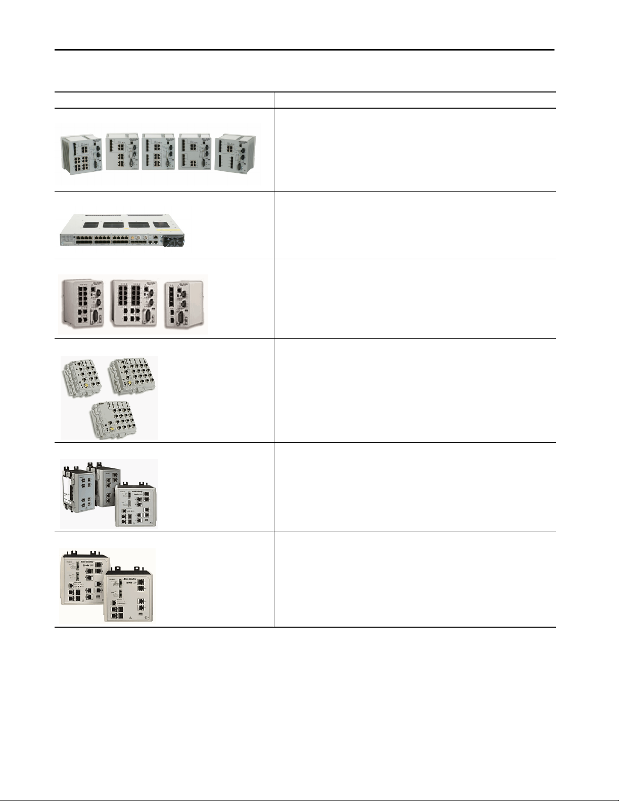
Table 1 - Stratix Switches
Switch Family Description
Stratix 5400 switches Layer 2 and Layer 3 scalable managed switches.
Available in 8…20 port versions, including all Gigabit port versions.
Stratix 5410 switches Layer 2 and Layer 3 scalable managed switches.
Available in 28-port versions.
Stratix 5700 switches Layer 2 scalable managed switches.
Available in 6…20 port versions.
ArmorStratix™ 5700 switches Layer 2 managed switches with IP67-rating for protection in extreme conditions.
Available in 8…24 port versions.
Stratix 8000 switches Layer 2 modular managed switches available with copper, fiber, small form-factor pluggable (SFP),
Stratix 8300 switches Layer 3 modular managed switches available with copper, fiber, SFP, and Power over Ethernet (PoE)
and Power over Ethernet (PoE) expansion modules.
Available in 6…26 port versions.
expansion modules.
Available in 6…26 port versions.
18 Rockwell Automation Publication 1783-UM007G-EN-P - February 2017
Page 19

About the Switches Chapter 1
EtherNet/IP CIP Interface
Stratix switches contain an EtherNet/IP network interface. The EtherNet/IP
network is an industrial automation network specification from the Open
DeviceNet Vendor Association (ODVA). The network uses the Common
Industrial Protocol (CIP) for its application layer and TCP/UDP/IP for its
transport and network layers. This interface is accessible via any of the Ethernet
ports by using the IP address of the switch.
CIP Network Connections
CIP is an object-oriented, connection-based protocol that supports two basic
types of messaging:
• Explicit
• Implicit (I/O)
A maximum of 32 connections is available. Both connection types must use the
switch password before any switch parameters can be written. The password is
the same one you enter during Express Setup.
Connection Description
Explicit Messaging Explicit Messaging connections provide generic, multi-purpose communication paths between two devices. These connections are often referred
Implicit messaging
(I/O connections)
to as messaging connections. Explicit messages provide request/response-oriented network communication. Each request is typically directed at
another data item. Explicit messages can be used to configure, monitor, and troubleshoot the switch.
The Explicit Messaging interface is used by the Studio 5000 Logix Designer® application.
I/O connections provide dedicated, special purpose communication paths between a producing application and one or more consuming
applications. The application-specific I/O data that moves through these connections is typically a fixed, cyclical structure.
The switch supports two I/O connection choices.
• Input Only
• Exclusive Owner
Both connections are cyclic and adjustable from 300...5000 ms.
The Input Only connection contains a data structure with status information on the switch in general and specific status on each of the ports. This
connection is multicast. Multiple controllers can share the connection.
The Exclusive Owner connection uses the same Input data structure as the Input Only connection, but adds an Output data structure. The Output
data contains a bit for each port that lets you enable or disable each port separately. While the Input data on this connection can be shared via
multicast by multiple controllers, only one controller can own the Output data. If a second controller attempts to open this connection, the
connection is rejected.
IMPORTANT Because the controller sends output data cyclically, the output data
overrides attempts by other software tools or visualization stations
to enable or disable a port.
EtherNet/IP QuickConnect Technology
EtherNet/IP QuickConnect technology enables EtherNet/IP devices to
quickly power up and join an EtherNet/IP network. Stratix switches can be a
part of a network configuration that uses QuickConnect technology. To use
the switches in a network that supports QuickConnect technology, you must
apply specific port settings to the switch. To configure the switch and apply the
port settings for QuickConnect technology, refer to the Ethernet
QuickConnect Application Technique, publication
Rockwell Automation Publication 1783-UM007G-EN-P - February 2017 19
ENET-AT001.
Page 20

Chapter 1 About the Switches
Lite Versus Full
Firmware Features
Some features for Stratix 5700 switches depend on whether the switches have
Full or Lite firmware. All Stratix 8000 and ArmorStratix 5700 switches have
Full firmware.
(Stratix 5700 Switches)
To determine the firmware type available for specific catalog numbers, see the
Stratix 5700 switch descriptions in
Feature Lite Firmware Full Firmware
CIP Sync (IEEE 1588) Separate option
Resilient Ethernet Protocol (REP)
FlexLinks
Quality of Service (QoS)
Spanning Tree Protocol (STP), Rapid Spanning Tree
Protocol (RSTP), MST (instances)
Internet Group Management Protocol (IGMP) Snooping
with querier
Virtual Local Area Networks (VLANs) with trunking 64 255
EtherChannel (link aggregation)
Port Threshold (Storm control and traffic shaping)
IPv6 support
Access Control Lists (ACL)
Static and interVLAN routing
CIP port control and fault detection
MAC ID Port security
IEEE 802.1x security
TACACS+, RADIUS authentication
Encryption (SSH, SNMPv3, HTTPS) Separate IOS firmware available as a separate item
Port mirroring
Syslog
Broken wire detection
Duplicate IP address detection •
Simple Network Management Protocol (SNMP)
Smartports
Dynamic Host Configuration Protocol (DHCP) per port
Command-line interface (CLI)
Compatible with Cisco tools: Cisco Network Assistant
(CNA); CiscoWorks
EtherNet/IP (CIP) interface
Device-level ring (DLR) Available on specific models that are listed on page 215
••
64 128
••
••
••
••
••
••
••
••
••
••
••
••
Table 166 on page 505.
•
•
•
•
•
•
•
•
•
•
20 Rockwell Automation Publication 1783-UM007G-EN-P - February 2017
Page 21

About the Switches Chapter 1
Software Features
Switch software features can be configured via Device Manager, the
Logix Designer application, or both:
•See
Configuration via Device Manager on page 47
•See
Configuration via the Studio 5000 Environment on page 53
All features can be configured via the command-line interface (CLI).
Some features are available only on select switches and expansion modules.
Table 2 - Software Features
Feature Switches Device Manager Logix Designer
Access Control Lists (ACLs) All
Alarms All
CIP Sync Time Synchronization/
Precision Time Protocol (PTP)
Device-level Ring (DLR) All Stratix 5400 switches
Dynamic Host Configuration Protocol
(DHCP) Persistence
DHCP for Ring Devices Stratix 5400 switches
Enhanced Interior Gateway Routing
Protocol (EIGRP)
EtherChannels All
Motion Prioritized QoS macros Stratix 5400 switches
Horizontal stacking Stratix 5410 switches: 1783-IMS28NAC, 1783-IMS28RAC, 1783-IMS28NDC, 1783-IMS28RDC
All Stratix 5400 switches
All Stratix 5410 switches
Stratix 5700 switches: 1783-BMS10CGN, 1783-BMS10CGP, 1783-BMS12T4E2CGNK,
1783-BMS12T4E2CGP, 1783-BMS20CGN, 1783-BMS20CGP, 1783-BMS20CGPK
ArmorStratix 5700 switches: 1783-ZMS4T4E2TGP, 1783-ZMS8T8E2TGP, 1783-ZMS4T4E2TGN,
1783-ZMS8T8E2TGN
All Stratix 8000 and 8300 switch base units (PTP traffic can be only forwarded through
expansion modules)
Stratix 5700 switches: 1783-BMS10CGP, 1783-BMS10CGN, 1783-BMS12T4E2CGL,
1783-BMS12T4E2CGP, 1783-BMS12T4E2CGNK,1783-BMS20CL, 1783-BMS20CA,
1783-BMS20CGL, 1783-BMS20CGP, 1783-BMS20CGN, 1783-BMS20CGPK
ArmorStratix 5700 switches: 1783-ZMS4E4T2GP, 1783-ZMS8E8T2GP, 1783-ZMS8E8T2GN,
1783-ZMS8E8T2GN
All
Stratix 5700 switches
ArmorStratix 5700 switches
Stratix 5400 switches with Layer 3 firmware
Stratix 5410 switches with Layer 3 firmware
Stratix 8300 base units
Stratix 5410 switches
Stratix 5700 switches with Full firmware
ArmorStratix 5700 switches
•
•
••
••
••
••
• —
•
•
——
—
—
—
—
Internet Group Management Protocol
(IGMP) Snooping with Querier
Multi-mode Express Setup Stratix 5400 switches
All
Stratix 5410 switches
Straitx 5700 switches
ArmorStratix 5700 switches
Stratix 8000 switches
Stratix 8300 switches
Rockwell Automation Publication 1783-UM007G-EN-P - February 2017 21
• —
••
Page 22

Chapter 1 About the Switches
Table 2 - Software Features (continued)
Feature Switches Device Manager Logix Designer
Network Address Translation (NAT) All Stratix 5400 switches
All Stratix 5410 switches
Stratix 5700 switches: 1783-BMS10CGN, 1783-BMS20CGN, 1783-BMS12T4E2CGNK
ArmorStratix 5700 switches: 1783-ZMS4T4E2TGN, 1783-ZMS8T8E2TGN
Network Time Protocol Stratix 5400 switches
Stratix 5410 switches
Stratix 5700 switches
ArmorStratix 5700 switches
Stratix 8000 switches
Stratix 8300 switches
Parallel Redundancy Protocol (PRP) Stratix 5400 switches
Stratix 5410 switches
Port Mirroring All
••
• —
• —
• —
Port Security All
Port Thresholds All
Power over Ethernet (PoE) Stratix 5400 switches: 1783-HMS4T4E4CGN, 1783-HMS4S8E4CGN, 1783-HMS4EG8CGN,
Resilient Ethernet Protocol (REP) All
Static and Connected Routing All
Open Shortest Path First (OSPF)
Gateway Routing Protocol
Simple Network Management Protocol
(SNMP)
Smartports All
Spanning Tree Protocol (STP) All
Virtual Local Area Networks (VLANs) All
1783-HMS8TG8EG4CGN, 1783-HMS4SG8EG4CGN,1783-HMS4EG8CGR,
1783-HMS8TG8EG4CGR, 1783-HMS4SG8EG4CGR
All Stratix 5410 switches
Stratix 5700 switches: 1783-BMS12T4E2CGNK, 1783-BMS12T4E2CGP, 1783-BMS12T4E2CGL
ArmorStratix 5700 switches: 1783-ZMS4T4E2TGP, 1783-ZMS8T8E2TGP, 1783-ZMS4T4E2TGN,
1783-ZMS8T8E2TGN
Stratix 8000 and 8300 expansion modules: 1783-MX04E, 1783-MX04T04E
Stratix 5400 switches with Layer 3 firmware
Stratix 5410 switches with Layer 3 firmware
Stratix 8300 base units
All
••
••
••
• —
• —
• —
• —
••
••
••
Hardware Features
See the following for a description of hardware features:
• For Stratix 5400, Stratix 5700, ArmorStratix 5700, and Stratix 8000/
8300 switches, see
• For Stratix 5410 switches, see
Table 3 on page 23.
Table 4 on page 24.
• For supported SFP modules, see the Stratix Ethernet Device
Specifications Technical Data, publication
22 Rockwell Automation Publication 1783-UM007G-EN-P - February 2017
1783-TD001.
Page 23

About the Switches Chapter 1
Table 3 - Hardware Features for Stratix 5400, Stratix 5700, ArmorStratix 5700, and Stratix 8000/8300 Switches
Feature Description
Power and relay connectors You connect the power and alarm signals to the front panel of a switch:
• Stratix 5400 switches—One connector provides primary DC power. A second connector provides secondary power. The two connectors are
physically identical. You can activate alarms for environmental, power supply, and port status alarm conditions. You can configure an alarm
to indicate open or closed contacts. There is no separate power connector for PoE.
• Stratix 5700 switches—One connector provides primary DC power and a second connector provides secondary power. The two connectors
are physically identical. You can activate alarms for environmental, power supply, and port status alarm conditions. You can configure an
alarm to indicate open or closed contacts. A separate power connector is required for PoE.
• ArmorStratix 5700 switches—One cable provides DC power from one or dual power sources. Relay connectors and alarm relays are
available for only catalog numbers 1783-ZMS4T4E2TGP, 1783-ZMS8T8E2TGP, 1783-ZMS4T4E2TGN, and 1783-ZMS8T8E2TGN. There is no
separate power connector for PoE.
• Stratix 8000/8300 switches—One connector provides primary DC power (supply A) and the major alarm signal. A second connector
provides secondary power (supply B) and the minor alarm signal. The two connectors are physically identical and are in the upper-left side
of the front panel.
The power and relay connectors also provide an interface for two independent alarm relays: the major alarm and the minor alarm. You can
activate the relays for environmental, power supply, and port status alarm conditions. You can configure an alarm to indicate open or closed
contacts. The relay itself is normally open, so under power failure conditions, the contacts are open. From the Command-line interface (CLI),
you can associate any alarm condition with one alarm relay or with both relays.
When dual power sources are operational for any of the switches, the switch draws power from the DC source with the higher voltage. If one of
the two power sources fail, the other continues to power the switch.
Console port To configure, monitor, and manage a switch, you can connect a switch to a computer through the console port:
• Stratix 5400 and Stratix 5700 switches—Connect to the console port with an RJ45-to-DB-9 adapter cable or a mini USB cable. The mini USB
driver is available in the firmware download section at
• ArmorStratix 5700 switches— Connect to the console port with an M12-to-DB-9 cable. See
• Stratix 8000/8300 switches—Connect to the console port with an RJ45-to-DB-9 adapter cable.
Dual-purpose (combo)
uplink ports
10/100 copper ports You can set the 10/100 copper ports to operate at 10 Mbps or 100 Mbps, full-duplex, or half-duplex. You can also set these por ts for speed and
100/1000 SFP ports The SFP ports on some models provide full-duplex, 100- or 1000-Mbps connectivity.
PoE/PoE+ ports The PoE ports available on some switches and expansion modules can be configured for PoE (IEEE 802.3af) or PoE+ (IEEE 802.3at Type 2). You
Auto-MDIX When connecting the switch to workstations, servers, and routers, straight-through cables are typically used. However, the automatic
You can configure the dual-purpose uplink ports available on some models for RJ45 (copper) or SFP (fiber) media types. Only one of these
connections in each of the dual-purpose ports can be active at a time. If both ports are connected, the SFP module port has priority.
You can set the copper RJ45 ports to operate at 10 Mbps, 100 Mbps, or 1000 Mbps, full-duplex, or half-duplex. You can configure them as fixed
10 Mbps, 100 Mbps, or 1000 Mbps (Gigabit) Ethernet ports and can configure the duplex setting. 1000 Mbps is not supported on all modules
with combo ports.
You can use approved Gigabit (or 100 Mbps) Ethernet SFP modules to establish fiber-optic connections to other devices. These transceiver
modules are field-replaceable and provide the uplink interfaces when inserted into an SFP module slot. You use fiber-optic cables with LC
connectors to connect to a fiber-optic SFP module. These ports operate only in full-duplex.
duplex autonegotiation in compliance with IEEE 802.3-2002. The default setting is autonegotiate.
When set for autonegotiation, the port senses the speed and duplex settings of the attached device. If the connected device also supports
autonegotiation, the switch port negotiates the connection with the fastest line speed that both devices support. The port also negotiates
full-duplex transmission if the attached device supports it. The port then configures itself accordingly. In all cases, the attached device must be
within 100 m (328 ft) of the switch.
ArmorStratix 5700 switches and Stratix 8000/8300 base switches do not have SFP ports.
can configure PoE /PoE+ ports in any combination of PoE and PoE+.
Stratix 5400 and ArmorStratix 5700 switches use one power connection for both basic power supply and PoE power supply.
Stratix 5700 switches and Stratix 8000/8300 expansion modules require a dedicated power supply for PoE.
See the following for PoE requirements:
• For Stratix 5400 switches, see
• For Stratix 5700 switches, see page 144.
• For ArmorStratix 5700 switches, see page 156.
• For Stratix 8000/8300 expansion modules, see page 174.
medium-dependent interface crossover (auto-MDIX) feature of the switch is enabled by default and reconfigures the ports to use either a
straight-through or crossover cable type.
The auto-MDIX feature is enabled by default. When the auto-MDIX feature is enabled, the switch detects the required cable type
(straight-through or crossover) for copper Ethernet connections and configures the interfaces accordingly.
You can use the Command-line interface (CLI) to disable the auto-MDIX feature. See the online help for more information.
page 83
http://www.rockwellautomation.com.
page 532.
Rockwell Automation Publication 1783-UM007G-EN-P - February 2017 23
Page 24

Chapter 1 About the Switches
Table 4 - Hardware Features for Stratix 5410 Switches
Feature Description
Dual power supply modules Depending on the switch model, one AC or DC power supply module comes pre-installed in the switch. You can order an optional second power
Alarm relay connector The front panel alarm port uses an RJ45 connector. You can connect four alarm inputs and one alarm output for environmental, power supply,
Console port To configure, monitor, and manage a switch, you can connect a switch to a computer through the console port:
10/100/1000 Ethernet,
PoE/PoE+ ports
100/1000 SFP ports 100/1000 SFP ports provide full-duplex, 100-Mbps or 1-Gbps connectivity.
1000 SFP ports 1000 SFP ports provide only 1-Gbps connectivity. These uplink ports are available on catalog numbers1783-IMS28GNDC, 1783-IMS28GNAC,
1000/10 Gigabit SFP/SFP+ ports 1000/10 Gigabit SFP/SFP+ ports provide full-duplex, 1-Gbps or 10-Gbps connectivity. The port speed is 1 Gbps when a 1000BASE SFP module
Auto-MDIX When connecting the switch to workstations, servers, and routers, straight-through cables are typically used. However, the automatic
Global positioning system (GPS) Not available in the current release.
Inter-range instrumentation
group (IRIG) time codes
Time of day (ToD)
synchronization
supply of any voltage type to provide redundancy and additional power for PoE devices:
• One power supply provides 60 W for PoE/PoE+.
• Two power supplies provide 185 W for PoE/PoE+.
The power-input terminal on the cable-side of the switch provides connections for high-voltage AC, high-voltage DC, or low-voltage DC power
for the two power supplies. When dual power sources are operational, the switch draws power from the power source with the higher voltage.
If one of the two power sources fail, the other continues to power the switch.
and port status conditions. You can configure an alarm to indicate open or closed contacts.
Connect to the console port with an RJ45-to-DB-9 adapter cable or a mini USB cable. The mini USB driver is available in the firmware download
http://www.rockwellautomation.com.
section at
You can set the 10/100/1000 ports to operate at 10 Mbps, 100 Mbps, or 1000 Mbps, full-duplex, or half-duplex. You can also set these por ts for
speed and duplex autonegotiation in compliance with IEEE 802.3-2002. The default setting is autonegotiate.
When set for autonegotiation, the port senses the speed and duplex settings of the attached device. If the connected device also supports
autonegotiation, the switch port negotiates the connection with the fastest line speed that both devices support. The port also negotiates
full-duplex transmission if the attached device supports it. The port then configures itself accordingly. In all cases, the attached device must be
within 100 m (328 ft) of the switch.
The ports can also be configured for PoE (IEEE 802.3af) or PoE+ (IEEE 802.3at Type 2):
• You can configure the ports in any combination of PoE and PoE+.
• A second power supply is required to support PoE+.
• The ports deliver up to 15.4 W of PoE and 30 W of PoE+.
The ports can be designated as high or low priority PoE/PoE+ ports. When two power-supply modules are installed, the system has enough
power to support all ports as PoE/PoE+ ports. If one of the power-supply modules fails, the power to the low priority ports is dropped, while
power to the high priority ports remains uninterrupted. For more information, see pages
The ports use RJ45 connectors with Ethernet pinouts. The maximum cable length is 100 m (328 ft).
1783-IMS28GRDC, and 1783-IMS28GRAC.
is installed and 10 Gbps when an 10GBASE SFP+ module is installed.
medium-dependent interface crossover (auto-MDIX) feature of the switch is enabled by default and reconfigures the ports to use either a
straight-through or crossover cable type.
The auto-MDIX feature is enabled by default. When the auto-MDIX feature is enabled, the switch detects the required cable type (straightthrough or crossover) for copper Ethernet connections and configures the interfaces accordingly.
You can use the Command-line interface (CLI) to disable the auto-MDIX feature. See the online help for more information.
314, 321, and 324.
24 Rockwell Automation Publication 1783-UM007G-EN-P - February 2017
Page 25

About the Switches Chapter 1
Memory Allocation
You can use Switch Database Management (SDM) templates to configure
system resources in the switch to optimize specific features. You can select a
template to provide maximum system usage for some functions. For example,
use the default template to balance resources, and use the access template to
obtain maximum ACL usage. To allocate hardware resources for different
usages, the switch SDM templates prioritize system resources to optimize
support for certain features.
Stratix 5400 Templates
The selected template optimizes the resources in the switch to support features
for eight routed interfaces and 1024 VLANs.
Layer 2 firmware models have the IPv4 Default template.
Layer 3 firmware models have these templates:
• IPv4 Default
• Dual IPv4/IPv6 Default
• IPv4 Routing
• Dual IPv4/IPv6 Routing
Table 5 - Stratix 5400 Templates
Feature Memory Allocation
IPv4 Default Dual IPv4/IPv6
Default
Unicast MAC addresses 16K 16K 16K 16K
IPv4 IGMP groups + multicast routes 1K 1K 1K 1K
IPv4 unicast routes 18K 5.25K 24K 6K
IPv6 multicast groups 0 1K 0 1K
IPv6 unicast groups 0 5.25K 0 7K
Directly connected IPv4 hosts 16K 4K 16K 4K
Directly connected IPv6 addresses 0 4K 0 4K
Indirect IPv4 routes 2K 1.25K 8K 2K
Indirect IPv6 unicast routes 0 5.25K 0 3K
IPv4 policy-based routing aces 0.125K 0.25K 0.375K 0.125K
IPv4/MAC QoS aces 1.875K 0.5K 0.5K 0.5K
IPv4/MAC security aces 1.875K 0.75K 1K 0.625K
IPv6 policy-based routing aces 0 0.25K 0 0.125K
IPv6 QoS aces 0 0.375K 0 0.125K
IPv6 security aces 0 0.375K 0 0.125K
IPv4 Routing Dual IPv4/IPv6
Routing
Rockwell Automation Publication 1783-UM007G-EN-P - February 2017 25
Page 26

Chapter 1 About the Switches
Stratix 5410 Templates
The selected template optimizes the resources in the switch to support features
for eight routed interfaces and 1024 VLANs.
Layer 2 firmware models have the Default template.
Table 6 - Stratix 5410 Layer 2 Firmware Model Template
Feature Memor y Allocation
Unicast MAC addresses 16K
IPv4 IGMP groups or IPv6 groups 1K IPv4
Direct routes 1K IPv4
Indirect routes 0.25K IPv4
IPv4 or IPv6 policy-based routing ACEs 0
IPv4 or IPv6 QoS ACEs 1K (IPv4 QoS)
IPv4 or IPv6 port or MAC security ACEs 1K (IPv4 ACL)
Layer 3 firmware models have these templates:
•Default
• Dual-default
• IPv4 Routing
•Dual-routing
Table 7 - Stratix 5410 Layer 3 Firmware Model Templates
Feature Memory Allocation
Default Dual-default IPv4 Routing Dual-routing
Unicast MAC addresses 16K 16K 16K 16K
IPv4 IGMP groups or IPv6
groups
Direct routes 16K IPv4 4K IPv4
Indirect routes 2K IPv4 1.25K IPv4
IPv4 or IPv6 policy-based
routing ACEs
IPv4 or IPv6 QoS ACEs 1.75K (IPv4 QoS) 0.5K (IPv4 QoS)
IPv4 or IPv6 port or
MAC security ACEs
1K IPv4 1K IPv4
1K IPv6
4K IPv6
1.25K IPv6
0.125K (IPv4 PBR) 0.25K (IPv4 PBR)
0.25K (IPv6 PBR)
0.5K (IPv6 QoS
1.75K (IPv4 ACL) 0.75K (IPv4 ACL)
0.5K (IPv6 ACL)
1K IPv4 1K IPv4
16K IPv4 4K IPv4
8K IPv4 2K IPv4
0.5K (IPv4 PBR) 0.125K (IPv4 PBR)
0.5K (IPv4 QoS) 0.5K (IPv4 QoS)
1K (IPv4 ACL) 0.625K (IPv4 ACL)
1K IPv6
4K IPv6
3K IPv6
0.125K (IPv6 PBR)
0.125K (IPv6 QoS)
0.125K (IPv6 ACL)
26 Rockwell Automation Publication 1783-UM007G-EN-P - February 2017
Page 27

About the Switches Chapter 1
Stratix 5700 and ArmorStratix 5700 Templates
The following SDM templates are available:
•Default
• Lanbase Routing
• Dual IPv4 and IPv6
If you enable static routing, or if you have more than 180 IGMP groups or
multicast routes., consider using the routing template.
If you use IPv6, consider using the Dual IPv4 and IPv6 template.
You can select SDM templates for IP version 4 (IPv4) to optimize these
features.
Table 8 - Stratix 5700 and ArmorStratix 5700 Templates
Feature Memory Allocation
Default Lanbase Routing Dual IPv4 and IPv6
Unicast MAC addresses 8K 4K 7.5K
IPv4 IGMP groups + multicast
routes
IPv4 unicast routes 0 4.25K 0
IPv6 multicast groups 0 0 0.375K
Directly connected IPv4 hosts 0 4K
Directly connected IPv6 addresses 0 0 0
Indirect IPv4 routes 0 0.25K
Indirect IPv6 routes 0 0 0
IPv4 policy-based routing aces 0 0
IPv4/MAC QoS aces 0.375K 0.375K 0.375K
IPv4/MAC security aces 0.375K 0.375K 0.375K
IPv6 policy-based routing aces 0 0 0
IPv6 QoS aces 0 0 0
IPv6 security aces 0 0 0.125K
0.25K 0.25K 0.25K
Rockwell Automation Publication 1783-UM007G-EN-P - February 2017 27
Page 28

Chapter 1 About the Switches
Stratix 8000 and 8300 Templates
The following SDM templates are recommended:
•Default
• Lanbase Routing
For static and connected routing, or if you have more than 180 IGMP groups
or multicast routes, you can use the Lanbase Routing template. Other SDM
templates are available, but are not covered in detail.
You can use SDM templates for IP Version 4 (IPv4) to optimize these features.
Table 9 - Stratix 8000 and ArmorStratix 8300 Templates
Feature Memory Allocation
Default Lanbase Routing
Unicast MAC addresses 8K 4K
IPv4 IGMP groups + multicast routes 0.25K 0.25K
IPv4 unicast routes 0 0.75
Directly connected IPv4 hosts 0 0.75
Indirect IPv4 routes 0 16
IPv4 policy-based routing ACEs 0 0
IPv4/MAC QoS ACEs 0.375K 0.375K
IPv4/MAC security ACEs 0.375K 0.375K
28 Rockwell Automation Publication 1783-UM007G-EN-P - February 2017
Page 29

Get Started
Topic Page
Express Setup Overview 30
Multi-mode Express Setup 34
Single-mode Express Setup 38
Configure Network Settings via Device Manager 39
Configure Network Settings via the Logix Designer Application 42
Default Global Macro 44
RSLinx Software and Network Who Support 44
Configuration via Device Manager 47
Configuration via the Studio 5000 Environment 53
User Administration via Device Manager 61
Configuration Files 62
Secure Digital (SD) Card 64
CompactFlash Memory Card (Stratix 8000/8300 Switches) 68
Firmware Updates 68
Cisco Network Assistant 69
Command-line Interface 70
Chapter 2
Rockwell Automation Publication 1783-UM007G-EN-P - February 2017 29
Page 30

Chapter 2 Get Started
Express Setup Overview
When you first install the switch, use Express Setup to perform these initial
setup tasks:
• Assign the switch an initial IP address. You can then access the switch
through the IP address for more configuration.
• Run the global macro to set initial configuration parameters, as
described on
page 43.
Express Setup Requirements
Multi-mode and single-mode versions of Express Setup are available depending
on your switch and IOS version:
• With IOS version 15.2(4)EA3 or later, all switches use multi-mode
Express Setup, as described on
• With IOS version 15.2(4)EA or earlier, all switches use single-mode
Express Setup, as described on
Multi-mode Express Setup enables you to configure network settings in either
Device Manager or the Studio 5000 Logix Designer® application. To configure
network settings via the Logix Designer application, you must have the Add-on
Profile (AOP) for Stratix® switches, version 11.01.xx or later.
page 34.
page 38.
30 Rockwell Automation Publication 1783-UM007G-EN-P - February 2017
Page 31

Get Started Chapter 2
You need this equipment to install the switch.
Component Requirement
Hardware
Processor 1 GHz or faster 32-bit (x86) or 64-bit (x64)
RAM 1 GB RAM (32-bit) or 2GB RAM (64-bit)
Hard disk space 16 GB (32-bit) or 20 GB (64-bit)
Software
Operating system Windows 7
Web browser Latest version of Internet Explorer™ or Firefox with JavaScript enabled.
Express Setup verifies the browser version when starting a session, and it does
not require a plug-in.
Computer-to-switch connection
(single-mode Express Setup or
multi-mode Express Setup in
Short Press mode)
Straight-through or crossover Category 5 Ethernet cable
or
(ArmorStratix™ 5700 switches) M12-to-RJ45 patchcord, such as Allen-Bradley®
catalog number 1585D-M4TBJM-2
For 1783-BMS4S2SGL or 1783-BMS4S2SGA switches, you also need a
Gigabit copper SFP module, such as Allen-Bradley catalog number
1783-SFP1GSX, or a Gigabit fiber-to-Ethernet media converter.
Before you begin, do the following:
• Single-mode Express Setup or multi-mode Express Setup in Short Press
mode:
– Disable other networks in your system.
– Set your computer to determine its IP address automatically versus
statically.
– Disable static DNS servers.
• Disable any wireless interface on your computer.
• Disable browser proxy settings.
• Make sure at least one switch Ethernet port is available for Express
Setup.
IMPORTANT For catalog numbers 1783-BMS4S2SGL and 1783-BMS4S2SGA, you
must use port Gi1/1 for Express Setup.
Do not use the console port for Express Setup.
• For Stratix 5700 or ArmorStratix 5700 switches, make sure that the SD
card is not inserted.
Rockwell Automation Publication 1783-UM007G-EN-P - February 2017 31
Page 32

Chapter 2 Get Started
Express Setup Button
Use the Express Setup button on the physical switch to perform Express Setup.
This Express Setup button is recessed behind the panel. To reach the button,
use a small tool, such as a paper clip.
WARNING: When you press the Express Setup button while power is on, an
electrical arc can occur. This could cause an explosion in hazardous location
installations.
Stratix 5400 Switch
Express Setup Button
Express Setup Button
Stratix 5410 Switch
32 Rockwell Automation Publication 1783-UM007G-EN-P - February 2017
Page 33

Stratix 5700 Switch
ArmorStratix 5700 Switch
Get Started Chapter 2
Express Setup Button
Express Setup Button
Stratix 8000/8300 Switch
Express Setup Button
Rockwell Automation Publication 1783-UM007G-EN-P - February 2017 33
Page 34

Chapter 2 Get Started
Multi-mode Express Setup
Multi-mode Express Setup has three modes:
IMPORTANT The Studio 5000 Logix Designer® application supports only Medium-press
mode.
• Short Press mode—You want to use Express Setup to enter the initial IP
address of the switch. You can then configure additional network
settings via Device Manager. To run Short Press mode, see page 35.
• Medium Press mode—You want to use a DHCP server to assign the
switch an IP address. You can then configure additional network
settings via Device Manager or the Logix Designer application. To run
Medium Press mode, see
page 36.
• Long Press mode—You want to reset the switch to use factory default
settings. To run Long Press mode, see
page 37.
Table 10 summarizes the function of each mode.
Table 10 - Mulit-mode Express Setup Modes
Attribute Short Press Mode Medium Press Mode Long Press Mode
Enable method Press and hold the Express Setup button until the
Setup status indicator flashes green during
seconds 1…5, and then release.
Setup status indicator Flashes green between seconds 1…5. Flashes red between seconds 6…10. Flashes green and red between seconds 16…20.
Function • The Express Setup management interface is
selected.
• The switch acts as a DHCP server on VLAN
1000 with an address of 169.254.0.1.
• Once the DHCP session is successfully
established, the switch assigns the computer
an IP address of 169.254.0.2 on VLAN 1000.
• The default login credentials are set to the
following:
– User name: [no user name/blank]
– Password: switch
• Express Setup parameters are completed via
Device Manager.
Press and hold the Express Setup button until the
Setup status indicator flashes red during seconds
6…10, and then release.
Between seconds 11…15 and after 21 seconds, the Setup status indicator turns off. If you release the
Express Setup button while the Setup status indicator is off, no Express Setup mode is enabled.
• A DHCP client request is sent out of all switch
ports on VLAN 1.
• VLAN 1 is configured for the IP address
returned by DHCP.
• The default login credentials are set to the
following:
– User name: [no user name/blank]
– Password: switch
• CIP (Common Industrial Protocol) is enabled
on VLAN 1 with the CIP security password set
to switch.
• Express Setup parameters are completed via
Device Manager or the Logix Designer
application.
Press and hold the Express Setup button until the
Setup status indicator flashes alternating green
and red during seconds 16…20, and then
release.
• All configuration settings (config.text,
vlan.dat, and private-config.text files) in
internal memory or on the SD card or
CompactFlash card are reset to factory
defaults.
• The switch restarts with factor y default
settings.
34 Rockwell Automation Publication 1783-UM007G-EN-P - February 2017
Page 35

Get Started Chapter 2
Run Multi-mode Express Setup in Short Press Mode
Be aware of the following conditions that cause the switch to exit Short Press
mode.
Condition Status Indicator Behavior
A non-default configuration exists on the switch. The Setup status indicator turns red for 10 seconds.
You do not connect to the Express Setup port within 2
minutes from when the port status indicator flashes
green.
No DHCP request is received for 2 minutes from when
you connect to the Express Setup port.
No browser session is started for 2 minutes after an IP
address is assigned to the computer.
You disconnect your computer from the switch before
the setup process is complete.
To run multi-mode Express Setup in Short Press mode, follow these steps.
1. Apply power to the switch.
The unconnected port status indicator and the Setup
status indicator turn off.
The Setup status indicator turns red for 10 seconds.
The unconnected port status indicator and the Setup
status indicator turn off.
All temporary configurations that are applied by Express
Setup, such as DHCP server, are removed.
When the switch powers on, it begins its power-on sequence. The
power-on sequence can take as many as 90 seconds to complete.
2. Make sure that the power-on sequence has completed by verifying that
the EIP Mod and Setup status indicators are flashing green.
If the switch fails the power-on sequence, the EIP Mod status indicator
turns red.
If you do not press the Express Setup button within 5 minutes after the
power-on sequence is complete, the Setup status indicator turns off.
However, you can still run Express Setup after the Setup status indicator
turns off.
3. Press and hold the Express Setup button until the Setup status indicator
flashes green during seconds 1…4, and then release.
The switch selects a port to use for Express Setup.
Rockwell Automation Publication 1783-UM007G-EN-P - February 2017 35
Page 36

Chapter 2 Get Started
4. Connect a Category 5 Ethernet cable from the flashing switch port to
the Ethernet port on a computer.
or
For 1783-BMS4S2SGL or 1783-BMS4S2SGA switches, do one of the
following:
• Insert a copper SFP module into the Gi1/1 port on the switch. Then
connect a Category 5 Ethernet cable from the SFP module to the
Ethernet port on the computer.
• Connect the Gi1/1 port on the switch to the Ethernet port on the
computer by using a fiber-to-Ethernet media converter.
IMPORTANT Port Gi1/1 does not flash during setup, but must be used to connect
1783-BMS4S2SGL or 1783-BMS4S2SGA switches to a computer.
Once you connect the switch to the computer, the following occurs:
• The status indicator for the port connected to the computer changes
from flashing green to solid green.
• The switch acts as a DHCP server on VLAN 1000 with an address of
169.254.0.1.
IMPORTANT The IP address of the switch for multi-mode Express Setup is
different than the IP address for single-mode Express Setup.
• The switch assigns the computer an IP address of 169.254.0.2 on
VLAN 1000.
• The Setup status indicator changes from flashing green to solid
green.
5. Proceed to
Configure Network Settings via Device Manager on page 39.
Run Multi-mode Express Setup in Medium Press Mode
Be aware of the following conditions that cause the switch to exit Medium
Press mode.
Condition Status Indicator Behavior
A non-default configuration exists on the switch. The Setup status indicator turns red for 10 seconds.
No DHCP response is received for 10 minutes from when
the switch broadcast the request.
IMPORTANT Before you begin, make sure that your system has a DHCP server configured
to assign the switch an IP address. You can configure a switch to be a DHCP
server, as described on
page 238.
36 Rockwell Automation Publication 1783-UM007G-EN-P - February 2017
Page 37

Get Started Chapter 2
To run multi-mode Express Setup in Medium Press mode, follow these steps.
1. Apply power to the switch.
When the switch powers on, it begins its power-on sequence. The
power-on sequence can take as many as 90 seconds to complete.
2. Make sure that the power-on sequence has completed by verifying that
the EIP Mod and Setup status indicators are flashing green:
• If the switch fails the sequence, the EIP Mod status indicator turns
red.
• If you do not press the Express Setup button within 5 minutes after
the sequence completes, the Setup status indicator turns off.
3. Press and hold the Express Setup button until the Setup status indictor
flashes red during seconds 6…10, and then release:
IMPORTANT You must complete the switch setup within 10 minutes of releasing
the Express Setup button. Otherwise, the switch exits Express Setup.
• The Setup status indicator flashes green during seconds 1…5, and
then red during seconds 6…10.
• The switch broadcasts a DHCP request out of all ports on VLAN 1.
• VLAN 1 is configured with the IP address returned by the DHCP
server.
• The default login credentials are set to the following:
– User name: [no user name/blank]
– Password: switch
• CIP is enabled on VLAN 1 with CIP security password set to
switch.
4. Configure network settings:
• To complete the configuration via Device Manager, see
page 39.
• To complete the configuration via the Logix Designer application,
see
page 42.
Run Multi-mode Express Setup in Long Press Mode
IMPORTANT Long Press mode overwrites all existing configuration files in internal or
external memory and resets the switch to use factory default settings.
Press and hold the Express Setup button until the Setup status indicator flashes
alternating green and red during seconds 16…20, and then release.
Upon release of the Express Setup button, the switch restarts with factory
default settings.
Rockwell Automation Publication 1783-UM007G-EN-P - February 2017 37
Page 38

Chapter 2 Get Started
Single-mode Express Setup
To run single-mode Express Setup, follow these steps.
1. Make sure that at least one switch Ethernet port is available for Express
Setup.
2. Apply power to the switch.
When the switch powers on, it begins its power-on sequence. The
power-on sequence can take up to 90 seconds to complete.
3. Make sure that the power-on sequence has completed by verifying that
the EIP Mod and Setup status indicators are flashing green.
If the switch fails the power-on sequence, the EIP Mod status indicator
turns red.
4. Press and release the Express Setup button.
Unlike multi-mode Express Setup, there is no time requirement for
when you release the Express Setup button.
5. Wait a few seconds until the status indicator on one of the unconnected
switch ports flashes green.
6. Connect a Category 5 Ethernet cable from the flashing switch port to
the Ethernet port on a computer.
or
For 1783-BMS4S2SGL or 1783-BMS4S2SGA switches, do one of the
following:
• Insert a copper SFP module into the Gi1/1 port on the switch. Then
connect a Category 5 Ethernet cable from the SFP module to the
Ethernet port on the computer.
• Connect the Gi1/1 port on the switch to the Ethernet port on the
computer by using a fiber-to-Ethernet media converter.
IMPORTANT Port Gi1/1 does not flash during setup, but must be used to connect
1783-BMS4S2SGL or 1783-BMS4S2SGA switches to a computer.
IMPORTANT If you wait too long to connect the cable, the Setup status indicator
turns off.
7. Proceed to
Configure Network Settings via Device Manager on page 39.
38 Rockwell Automation Publication 1783-UM007G-EN-P - February 2017
Page 39

Get Started Chapter 2
Configure Network Settings via Device Manager
To configure network settings via Device Manager after you run Express Setup,
follow these steps.
1. Access Device Manager, as described on
If the Express Setup window does not appear, try the following:
• Verify that your network adapter is set to accept a DHCP address
• Enter the URL of a well-known website in your browser to be sure
that the browser is working correctly. Your browser then redirects to
Express Setup.
• Verify that any proxy settings or pop-up blockers are disabled on your
browser.
• Verify that any wireless interface is disabled on the computer.
2. On the Express Setup window, complete the fields, as described in
Table 11.
To view fields for Common Industrial Protocol (CIP), click Advanced
Settings.
page 48.
Rockwell Automation Publication 1783-UM007G-EN-P - February 2017 39
Page 40

Chapter 2 Get Started
Table 11 - Express Setup Fields
Field Description
Network Settings
Host Name The name of the device.
Management Interface (VLAN ID) The name and ID of the management VLAN through which the switch is managed. The management VLAN is the broadcast domain through
IP Assignment Mode The IP Assignment mode determines whether the switch IP information is manually assigned (static) or is automatically assigned by a
IP Address The IP address and associated subnet mask are unique identifiers for the switch in a network:
Default Gateway (optional) The IP address for the default gateway. A gateway is a router or a dedicated network device that enables the switch to communicate with
NTP Server The IP address of the Network Time Protocol (NTP) server. NTP is a networking protocol for clock synchronization between computer systems
User Enter the user name.
Password, Confirm Password
(initial setup only)
Advanced Settings
Enable CIP VLAN Check the checkbox to enable CIP on a VLAN. You can specify the settings required for CIP or check the Same As Management VLAN checkbox.
CIP VLAN The VLAN on which CIP is enabled. The CIP VLAN can be the same as the management VLAN or you can isolate CIP traffic on another VLAN that
IP Address The IP address and subnet mask for the CPI VLAN if the CIP VLAN differs from the management VLAN. The format is a 32-bit numeric address
Same As Management VLAN Check the checkbox to make the settings for the CIP VLAN the same as the management VLAN.
which management traffic is sent between specific users or devices. It provides broadcast control and security for management traffic that
must be limited to a specific group of users, such as the administrators of your network. It also provides secure administrative access to all
devices in the network.
Choose an existing VLAN as the management VLAN. The default management VLAN ID is 1 and the VLAN name is default.
Valid IDs for single-mode Express Setup: 1…1001
Valid IDs for multi-mode Express Setup: 1…4096
IMPORTANT: Be sure that the switch and your network management station are in the same VLAN. Otherwise, you lose management
connectivity to the switch.
Dynamic Host Configuration Protocol (DHCP) server. The default is Static.
We recommend that you click Static and manually assign the IP address for the switch. You can then use the same IP address whenever you
want to access Device Manager.
If you click DHCP, the DHCP server automatically assigns an IP address, subnet mask, and default gateway to the switch. Unless restarted, the
switch continues to use the DHCP-assigned information, and you are able to use the DHCP-assigned address to access Device Manager.
For a manually assigned IP address in a network that uses a DHCP server, make sure that the IP address is not within the range of addresses
that the DHCP server assigns. Otherwise, IP address conflicts can occur between the switch and another device.
• The IP address format is a 32-bit numeric address that is written as four numbers that are separated by periods. Each number can be from
0…255.
• The subnet mask is the network address that identifies the subnetwork (subnet) to which the switch belongs. Subnets are used to segment
the devices in a network into smaller groups. The default is 255.255.255.0.
IMPORTANT: If you run multi-mode Express Setup in Medium Press mode, the IP Address field displays the address received from the DHCP
server. If you change the address, the connection drops. To re-establish the connection with the new address, close your web browser and go
to the address you specified.
Make sure that the IP address that you assign to the switch is not assigned to another device in your network. The IP address and the default
gateway cannot be the same.
devices in other networks or subnetworks. The default gateway IP address must be part of the same subnet as the switch IP address. The
switch IP address and the default gateway IP address cannot be the same.
If all of your devices are in the same network and a default gateway is not used, you do not need to enter an IP address in this field. This field is
enabled only if the IP assignment mode is Static.
If your network management station and the switch are in different networks or subnetworks, you must specify a default gateway. Otherwise,
the switch and your network management station cannot communicate with each other.
over packet-switched, variable-latency data networks.
The password for the switch can have up to 63 alphanumeric characters, can start with a number, is case-sensitive, and can have embedded
spaces. The password cannot be one digit, it cannot contain a ? or a tab, and it does not allow spaces at the beginning or the end. The default is
switch.
To complete initial setup, you must change the password from the default password, switch.
This password is also used as the Control Industrial Protocol (CIP) security password. We recommend that you provide a password to the switch
to secure access to Device Manager.
is already configured on this device.
that is written as four numbers that are separated by periods. Each number can be from 0…255.
Make sure that the IP address that you assign to this device is not being used by another device in your network.
40 Rockwell Automation Publication 1783-UM007G-EN-P - February 2017
Page 41

Get Started Chapter 2
Table 11 - Express Setup Fields (continued)
Field Description
Enable SSH Check the checkbox to enable Secure Shell (SSH) sessions on the switch. You can use SSH to access the command-line interface (CLI) for switch
Telnet, CIP and Enable Password
(optional), Confirm Password
Same As Admin Password Sets the password that is used for Telnet and CIP security to the same user password specified under Network Settings.
configuration. For more information about the CLI, see page 70.
The password that is used for Telnet and CIP security.
3. Click Submit.
The switch initializes its configuration for typical industrial
EtherNet/IP applications by running the global macro as described on
page 43. You can then log on to Device Manager for further
configuration or exit the application.
4. Turn off DC or AC power at the source, disconnect any cables to the
switch, and install the switch in your network.
IMPORTANT For 1783-BMS4S2SGL or 1783-BMS4S2SGA switches, make sure that
DC power is disconnected before disconnecting Ethernet cables.
5. If you used single-mode Express Setup or multi-mode Express Setup in
Short Press mode, refresh the computer IP address:
• For a dynamically assigned IP address, disconnect the computer from
the switch and reconnect the computer to the network. The network
DHCP server assigns a new IP address to the computer.
• For a statically assigned IP address, change it to the previously
configured IP address.
6. For Stratix 5400 and Stratix 5410 switches, synchronize the SD card
that came with the switch with the internal memory of the switch:
• To synchronize the SD card via Device Manager, see
page 65.
• To synchronize the SD card via the Logix Designer application, see
page 67.
After initial setup with Express Setup, you can change the settings if you want
to move the switch to another management VLAN or to another network. To
change Express Setup settings after initial setup, from the Admin menu in
Device Manager, choose Express Setup.
Rockwell Automation Publication 1783-UM007G-EN-P - February 2017 41
Page 42

Chapter 2 Get Started
Configure Network Settings via the Logix Designer Application
To configure network settings via the Logix Designer Application after
running multi-mode Express Setup in Medium Press mode, follow these steps.
1. If you have not yet added the switch to a controller project, complete
Steps
1…3 on page 53.
2. Configure general properties, as described
page 55.
Be sure to specify the IP address assigned to the switch by the DHCP
server.
3. Go online with the controller, and then open the Module Properties
dialog box for the switch.
4. In the navigation pane, click Switch Configuration.
5. When the Express Setup dialog box appears, complete the fields.
Field Description
Internet Protocol (IP) Settings Click the method to use for assigning the swtich an IP address:
• Manually Configure IP settings (default)—The switch uses a manually-assigned, static IP address.
If you manually assign the IP address of the switch and your network uses a DHCP server, make sure that the IP address is not within the
range of addresses that the DHCP server assigns. Otherwise, IP address conflicts can occur between the switch and another device.
• Obtain IP settings automatically using DHCP—A Dynamic Host Configuration Protocol (DHCP) server automatically assigns the switch an IP
address, subnet mask, and default gateway.
Unless restarted, the switch continues to use the DHCP-assigned information.
Physical Module IP Address Displays the IP address assigned to the switch by the DHCP server during Express Setup. This value must match the IP address on the General
42 Rockwell Automation Publication 1783-UM007G-EN-P - February 2017
view. If you change the assigned IP address, make sure that the new IP address is not assigned to another device in your network. The IP
address and the default gateway cannot be the same.
IMPORTANT: If you reconfigure your switch with another IP address, you can lose communication with the switch when you click Set. To
correct this problem, you must return to the Express Setup and General view, set the new IP address, and download to the controller.
Page 43

Get Started Chapter 2
Field Description
Subnet Mask Displays the IP address assigned to the switch by the DHCP server during Express Setup. The subnet mask is the network address that identifies
Host Name Type a name to identify the switch. The name can be up to 64 characters and can include alphanumeric and special characters (comma and
Gateway Address Displays the gateway address assigned to the switch by the DHCP server during Express Setup. A gateway is a router or a dedicated network
Network Time Protocol (NTP)
Server
User Displays the default user name: Admin
Password, Confirm Password The password for the switch can have up to 63 alphanumeric characters, can start with a number, is case-sensitive, and can have embedded
Management Interface (VLAN) Choose a management VLAN. The default management VLAN ID is 1.
the subnetwork (subnet) to which the switch belongs. Subnets are used to segment the devices in a network into smaller groups.
The subnet mask is a 32-bit number. Set each octet between 0…255. The default is 255.255.255.0.
dash).
device that enables the switch to communicate with devices in other networks or subnetworks. The default gateway IP address must be part of
the same subnet as the switch IP address. The switch IP address and the default gateway IP address cannot be the same.
If all of your devices are in the same network and a default gateway is not used, you do not need to enter an IP address in this field. This field is
enabled only if the IP assignment mode is Static.
If your network management station and the switch are in different networks or subnetworks, you must specify a default gateway. Otherwise,
the switch and your network management station cannot communicate with each other.
IMPORTANT: Communication is disrupted when you change the gateway (IP) address.
(Optional). Type the IP address of the NTP server. NTP is a networking protocol for clock synchronization between computer systems over
packet-switched, variable-latency data networks.
spaces. The password cannot be one digit, it cannot contain a ? or a tab, and it does not allow spaces at the beginning or the end. The default
password is switch.
To complete initial setup, you must change the password from the default password.
This password is also used as the Control Industrial Protocol (CIP) security password. You must provide a password to the switch to secure
access to Device Manager.
The management VLAN through which the switch is managed. The management VLAN is the broadcast domain through which management
traffic is sent between specific users or devices. It provides broadcast control and security for management traffic that must be limited to a
specific group of users, such as the administrators of your network. It also provides secure administrative access to all devices in the network.
IMPORTANT: Be sure that the switch and your network management station are in the same VLAN. Otherwise, you lose management
connectivity to the switch.
6. Click OK.
The switch initializes its configuration for typical industrial
EtherNet/IP applications by running the global macro as described on
page 43. You can then use the AOP for further configuration or exit the
application.
7. Turn off DC or AC power at the source, disconnect any cables to the
switch, and install the switch in your network.
IMPORTANT For 1783-BMS4S2SGL or 1783-BMS4S2SGA switches, make sure that
DC power is disconnected before disconnecting Ethernet cables.
8. For Stratix 5400 and Stratix 5410 switches, synchronize the SD card
that came with the switch with the internal memory of the switch, as
described on
page 67.
Rockwell Automation Publication 1783-UM007G-EN-P - February 2017 43
Page 44

Chapter 2 Get Started
Default Global Macro
Once you complete Express Setup, the switch runs a default global macro
(ab-global). This macro configures the switch for industrial automation
applications that use the EtherNet/IP protocol. This macro sets many
parameters, including these major settings:
• Enable IGMP snooping and querier
• Enable CIP
• Enables alarms, SYSLOG, and SNMP notifications
• Enables Rapid Spanning Tree (RSTP), BPDU Guard, BPDU Filter, and
loop guard
• Configure Quality of Service (QoS) settings and classify CIP, PTP, and
other traffic (does not apply to switches with lite firmware revisions)
IMPORTANT The default QoS setting applied by the default global macro assigns the
same priority to traffic for CIP and traffic for Integrated Motion on the
EtherNet/IP network applications. However, you can assign a higher
priority to motion traffic by manually applying optional QoS macros after
you run Express Setup. For more information, see
If you do not run Express Setup to initialize the switch, the global macro does
not run. You can use the CLI, described on
page 70, to run the global macro.
page 248.
RSLinx Software and Network Who Support
The EtherNet/IP network interface also supports the List Identity command
that is used by CIP-based network tools, such as the RSLinx® software RSWho
function. RSWho enables you to locate and identify your switch on the
network by using the electronic data sheet (EDS) files.
To access the RSWho function, from the RSLinx software toolbar, choose
Communications > RSWho.
IMPORTANT After using the RSWho function, if you access the switch and view the
Ethernet link counters, you see the counts for only the first port (Port Gi1/1).
Electronic Data Sheet (EDS) Files
Electronic Data Sheet (EDS) files are text files that are used by network
configuration tools, such as RSNetWorx™ for EtherNet/IP software. EDS files
help you identify products and commission them on a network. EDS files
contain details about the readable and configurable parameters of the device.
They also provide information about the I/O connections the device supports
and the content of the associated data structures.
If you are using the switch in a system without a Rockwell Automation Logix
controller, you cannot use the AOP supplied with Logix controllers. You must
use information from the EDS files to configure the I/O connection.
44 Rockwell Automation Publication 1783-UM007G-EN-P - February 2017
Page 45

Get Started Chapter 2
EDS files for the Stratix switches are included with the following software
packages:
• RSLinx software
• RSLogix 5000® software
• RSNetWorx for EtherNet/IP software
You can also obtain the EDS files in either of these two ways:
• By downloading it from
http://www.rockwellautomation.com/resources/eds/.
• By using the RSLinx EDS Hardware Installation tool.
To upload the EDS files directly from the switch over the network, follow these
steps.
1. From the Start menu, choose Programs >
Rockwell Software >RSLinx >Tools > EDS Hardware Installation Tool.
2. To launch the EDS Wizard and add the selected hardware description
and associated files, click Add.
Data Accessible with CIP
The CIP interface lets you access the information in Table 12.
Table 12 - Data Accessible with CIP
Data Type Details
Input data via I/O connection • Link status per port: not connected, connected
Output data via I/O connection Port disable per port: enabled, disabled
• Unauthorized device per port: OK, not OK
• Unicast threshold exceeded per port: OK, exceeded
• Multicast threshold exceeded on each port: OK, exceeded
• Broadcast threshold exceeded on each port: OK, exceeded
• Port bandwidth utilization per port: value in %
• Alarm relay major: OK, tripped
• Multicast groups active: quantity
Rockwell Automation Publication 1783-UM007G-EN-P - February 2017 45
Page 46

Chapter 2 Get Started
Table 12 - Data Accessible with CIP (continued)
Data Type Details
Other status data • Module identification (vendor ID, device type, product code, product name, revision, serial number)
Configuration data • Major and minor revision of switch
Smartport assignment per port • Role
Save and restore of switch configuration Via File Obj
• Major/minor fault status, I/O connection, module identity match
• Active alarms
• Major alarm relay (open, closed)
• Active faults
• Switch uptime since last restart
• Switch internal temperature in degrees Centigrade
• Management CPU utilization in percentage
• Power supply A present: yes, no
• Power supply B present: yes, no
• Number of active multicast groups
• IOS release version
• DLR ring status, members, and faults
• CIP connection counters: open/close requests, open/close rejects, timeouts
• Port alarm status per port: OK, Link Fault, Not Forwarding, Not Operating, High Bit Error Rate
• Port fault status per port: Error Disable, SFP Error, Native VLAN Mismatch, MAC address Flap Condition, Security Violation
• Port diagnostic counters per port: Ethernet interface counters (10), Ethernet media counters (12)
• Link status
• Traffic threshold exceeded per port: unicast, multicast, broadcast
• Cable diagnostics per port selected
• DHCP pool display: name, starting and ending IP address
• NAT: display name of instance, VLANs assigned per instance
• NAT diagnostics: active translations, total translated packets, blocked and pass-through traffic, ICMP and ARP fixups
• Electronic keying (Exact Match, Disable Keying)
• Connection (Input Data, Data)
• Data connection password
• Requested packet interval (RPI)
• Inhibit module
• Major fault on controller if connection fails while in Run mode
• Use unicast connections over EtherNet/IP
• Module fault display
• IP addressing method: Manual, DHCP
• IP address, subnet mask, primary and secondary DNS server address, default gateway (all if static)
• Host name
• Administration: contact name, geographic location
• Spanning Tree Mode (MST, RSTP, PVST+, RPVST+)
• Dual-power supply alarm enable
• Port configuration per port: enable/disable, auto-negotiate, speed, duplex
• Power over Ethernet (PoE): mode, status, power limit, power used, total power supported, total power used, remaining power
available
• Smartports and VLANs: assign roles per port, VLAN ID and name
• Port thresholds (incoming: unicast, multicast, broadcast, all outgoing traffic) rate limiting threshold per port: in packets per
second, bits per second, or percentage
• Port security: enable, allowed MAC IDs per port, dynamic, static
• DHCP pool: enable, delete, refresh, create
• DHCP address assignment per port
• Time sync configuration: enable per port, port state
• NAT configuration: create instance (private-to-public, public-to-private, traffic permits, and fixups)
•VLAN
46 Rockwell Automation Publication 1783-UM007G-EN-P - February 2017
Page 47

Get Started Chapter 2
Configuration via Device Manager
Device Manager is a web-based management tool for configuring, monitoring,
and troubleshooting individual switches. You can display Device Manager
from anywhere in your network through a web browser.
Device Manager displays real-time views of switch configuration and
performance. It simplifies configuration tasks with features such as Smartports.
It uses graphical, color-coded displays, such as the front panel view, graphs, and
animated indicators to simplify monitoring tasks. It provides alert tools to help
you to identify and to solve networking problems.
Table 13 - Device Manager Hardware Requirements
Attribute Requirement
Processor speed 1 GHz or faster (32 bit or 64 bit)
RAM 1 GB (32 bit) or 2 GB (64 bit)
Available hard disk space 16 GB (32 bit) or 20 GB (64 bit)
Number of colors 256
Resolution 1024 x 768
Font size Small
Table 14 - Device Manager Software Requirements
Web Browser Version
Microsoft Internet Explorer Latest version with JavaScript enabled
Mozilla Firefox Latest version with JavaScript enabled
Rockwell Automation Publication 1783-UM007G-EN-P - February 2017 47
Page 48

Chapter 2 Get Started
Access Device Manager
With IOS version 15.2(5)EA.fc4 and later, Device Manager provides a secure
connection via the latest version of Internet Explorer or Firefox. Security
messages from your browser can appear when you access Device Manager.
To make sure that Device Manager runs properly, disable any pop-up blockers
or proxy settings in your browser and any wireless clients on your computer.
Device Manager verifies the browser version when starting a session to be sure
that the browser is supported.
To access Device Manager, follow these steps.
1. Start a web browser session and go to the switch IP address.
IMPORTANT If you set up bookmarks for accessing previous versions of
Device Manager, be sure to recreate new bookmarks. Addresses that
end with /homed.shtml do not provide the latest login
authentication method.
2. (Internet Explorer). If the following message appears, click Continue to
this website.
(Firefox). If the following message appears, do the following:
a. Click Advanced.
b. Click Add Exception.
48 Rockwell Automation Publication 1783-UM007G-EN-P - February 2017
Page 49

c. Click Confirm Security Exception.
Get Started Chapter 2
Rockwell Automation Publication 1783-UM007G-EN-P - February 2017 49
Page 50

Chapter 2 Get Started
3. On the Device Manager Login window, enter the switch name and
password.
50 Rockwell Automation Publication 1783-UM007G-EN-P - February 2017
Page 51

Get Started Chapter 2
Configure Port Settings
The basic port settings determine how data is received and sent between the
switch and the attached device. You can change these settings to fit your
network needs and to troubleshoot network problems. The settings on a
switch port must be compatible with the port settings of the connected device.
To change basic port settings, from the Configure menu, choose Port Settings.
Table 15 lists the basic settings for the switch ports. To change these settings,
click the radio button next to the port name and click Edit to display the Edit
Physical Port window.
Rockwell Automation Publication 1783-UM007G-EN-P - February 2017 51
Page 52

Chapter 2 Get Started
Table 15 - Port Settings
Field Description
Port Name The number of the switch port, including port type, such as Fa for Fast Ethernet and Gi for Gigabit Ethernet, and the specific port number:
Description The description of the switch port.
Port Status The state of the switch port. The default is Enabled. You can change this setting on the Edit Physical Port window by checking or clearing the
Speed The operating speed of the switch port. You can choose Auto (autonegotiation) if the connected device can negotiate the link speed with the switch
Duplex The Duplex mode of the switch port:
Auto-MDIX Whether the automatic medium-dependent interface crossover (auto-MDIX) feature can automatically detect the required cable connection type
Media Type The active port type (either the RJ45 port or the SFP module port) of a dual-purpose uplink port.
Operational Mode The operational state of the port. Displays the administrative mode or Down (if disabled).
Access VLAN The VLAN that an interface belongs to and carries traffic for, when the link is configured as or is acting as a nontrunking interface.
Administrative Mode Displays one of the following administrative modes:
• Gi/1 is the gigabit port 1 of the switch.
• Fa1/1 is Fast Ethernet port 1 on the switch.
We recommend that you provide a port description to help identify the port during monitoring and troubleshooting. The description can be the
location of the connected device or the name of the person using the connected device.
Administrative checkbox.
We recommend disabling the port if the port is not in use and is not attached to a device.
An example of when to change this setting is during troubleshooting. You can troubleshoot a suspected unauthorized connection by administratively
disabling the port.
port. The default is Auto.
We recommend that you use the default so that the speed setting on the switch port automatically matches the setting on the connected device.
Change the switch port speed if the connected device requires a specific speed.
An example of when to change this setting is during troubleshooting. If you are troubleshooting a connectivity problem, you can change this setting to
see if the switch port and connected device have a speed mismatch.
• Auto (autonegotiation) if the connected device can negotiate with the switch.
• Full (Full-duplex mode) if both devices can send data simultaneously.
• Half (Half duplex mode) if one or both devices cannot send data simultaneously.
The default is Auto.
On Gigabit Ethernet ports, you cannot set the port to Half-duplex mode if the port speed is set to Auto.
We recommend that you use the default so that the duplex setting on the switch port automatically matches the setting on the connected device.
Change the Duplex mode on the switch port if the connected device requires a specific mode.
An example of when to change this setting is during troubleshooting. If you are troubleshooting a connectivity problem, you can change this setting to
verify if the switch port and connected device have a duplex mismatch.
(straight-through or crossover) and configure the connection appropriately. The default is Enable.
This setting is not available on the SFP module ports.
By default, the switch detects whether the RJ45 port or SFP module port of a dual-purpose port is connected and uses the por t accordingly. Only one
port can be active at a time. If both ports are connected, the SFP module port has priority. You cannot change the priority setting.
Choose from the following media types:
• SFP—The SFP module port is active. If you choose this option, the speed and duplex displays the current settings and auto-MDIX displays N/A.
• RJ45—The RJ45 port is active. If you choose this option, you can set the port speed, duplex, and auto-MDIX values.
• Auto (autonegotiation)—Either port can be active. If you choose this option, the speed and duplex is set to auto and auto-MDIX displays N/A.
The default is Auto.
• Access—The interface is in permanent nontrunking mode and negotiates to convert the neighboring link into a nontrunk link even if the
neighboring interface is a trunk interface. If you choose this option, also choose an Access VLAN. An access port belongs to and carries the traffic of
only one VLAN (unless it is configured as a voice VLAN port).
• Trunk—The interface is in permanent trunking mode and negotiates to convert the neighboring link into a trunk link even if the neighboring
interface is not a trunk interface. If you choose this option, also choose whether to allow All VLANs or specified VLAN IDs.
• Dynamic Auto—The interface converts the link to a trunk link if the neighboring interface is set to trunk or desirable mode. This mode is the
default setting. If you choose this option, specify an Access VLAN to use when the link is in access mode. Also specify whether to allow All VLANs or
specified VLAN IDs when the link is in trunk mode.
• Dynamic Desirable—If the neighboring interface is set to Trunk, Dynamic Desirable, or Auto mode, the interface converts the link to a trunk link. If
you choose this option, specify an Access VLAN to use when the link is in access mode. Also choose whether to allow All VLANs or specified VLAN IDs
when the link is in Trunk mode.
• Routed—The interface acts like a port on a router but does not have to be connected to a router. A routed port is not associated with a particular
VLAN, as is an access port. A routed port behaves like a regular router interface, except that it does not support VLAN subinterfaces. Routed ports
can be configured with a Layer 3 routing protocol. A routed port is a Layer 3 interface only and does not support Layer 2 protocols, such as DTP and
STP. Routed ports are supported only on switches running the IP base or IP services image.
The default setting is Dynamic Auto.
52 Rockwell Automation Publication 1783-UM007G-EN-P - February 2017
Page 53

Get Started Chapter 2
Configuration via the Studio 5000 Environment
You can manage the switch by using the Logix Designer application in the
Studio 5000® environment. The Logix Designer application is IEC 61131-3
compliant and offers relay ladder, Structured Text, function block diagram, and
sequential function chart editors for you to develop application programs.
Table 16 - Logix Designer Hardware Requirements
Attribute Requirement
Processor speed Pentium II 450 MHz min
Pentium III 733 MHz (or better) recommended
RAM 128 MB min
256 MB recommended
Free hard disk space 3 GB
Optical drives DVD
Video requirements 256-color VGA graphics adapter
800 x 600-min resolution (True Color 1024 x 768 recommended)
Resolution 800 x 600-min resolution (True Color 1024 x 768 recommended)
To add the switch to a controller project in the Logix Designer application,
follow these steps.
IMPORTANT These steps are required before you can go online to configure and monitor
the switch. You must be online to view and configure most switch
parameters in the Logix Designer application.
1. Open the project file for the controller to monitor the switch.
2. Right-click Ethernet and choose New Module.
Rockwell Automation Publication 1783-UM007G-EN-P - February 2017 53
Page 54

Chapter 2 Get Started
3. On the Select Module Type dialog box, select the switch and click
Create.
If you do not see the switch on the list, you can obtain the AOP from the
Rockwell Automation support website:
http://www.rockwellautomation.com/support/
54 Rockwell Automation Publication 1783-UM007G-EN-P - February 2017
Page 55

General Properties
To configure general properties, follow these steps.
1. In the navigation pane, click General and complete the fields.
Get Started Chapter 2
IMPORTANT Make sure that the IP address and host name match the values you used
during Express Setup. On the Module Properties dialog box, you can choose
either an IP address or host name. Only one of these two choices is
enabled.
Field Description
Name A name that you choose for the switch.
Description A description that helps you remember something important about the switch.
Ethernet Address Choose one of the following:
• Private Network—The IP address of your private network.
• IP Address—The IP address assigned to the switch during Express Setup.
• Host Name—The host name that is provided on initial configuration when you
performed Express Setup. The host name requires that you have a DNS server that is
configured on the network for the Ethernet interface module of the controller.
Rockwell Automation Publication 1783-UM007G-EN-P - February 2017 55
Page 56

Chapter 2 Get Started
2. In the Module Definition area, click Change.
3. On the Module Definition dialog box, complete the fields and click
OK.
Field Description
Revision The major and minor revision of the switch:
Electronic Keying Choose one of the following:
Connection Choose one of the following:
Data Connection Password (Data connections only). Enter the password for accessing the switch.
Switch Base
(Stratix 8000/8300 switches)
Switch Expansion 1
(Stratix 8000/8300 switches)
Switch Expansion 2
(Stratix 8000/8300 switches)
• Major revision: 1…128
• Minor revision: 1…255
• Compatible Module (default)
• Exact Match
• Disable Keying
• Input Data (default): Enables only an input data connection.
• Data: Enables an input and output data connection.
ATTENTION: This selection enables output tags, which can disable ports and interrupt connections to and through the switch. You can
disable a switch port by setting the corresponding bit in the output tag. The output bits are applied every time that the switch receives the
output data from the controller when the controller is in Run mode. When the controller is in Program mode, the output bits are not applied.
If the corresponding output bit is 0, the port is enabled. If you enable or disable a port by using Device Manager or the CLI, the port setting
can be overridden by the output bits from the controller on the next cyclic update of the I/O connection. The output bits always take
precedence, regardless of whether the Device Manager Web interface or CLI was used to enable or disable the port.
Displays the switch base catalog number for the selected module.
(14, 18, 22 and 26 port switches only). The catalog number for the copper or fiber expansion modules you are using.
For 14 and 18-port switches, user selection of the expansion module is supported.
For 22 and 26-port switches, Switch Expansion 1 displays 1783-MX08T. User selection of the expansion module is not supported.
(22 and 26 port switches only). The catalog number for the copper or fiber expansion modules you are using. User selection of the expansion
module is supported.
56 Rockwell Automation Publication 1783-UM007G-EN-P - February 2017
Page 57

Connection Properties
In the navigation pane, click Connection.
Get Started Chapter 2
Table 17 - Connection Fields
Field Description
Requested Packet Interval (RPI) Enter a value between 300…5000.
Inhibit Module Check to disable communication between the controller and the switch.
Clear the checkbox to restore communication.
Major Fault on Controller If Connection Fails While in Run mode Check to have the controller create a major fault if connection fails in Run mode.
Use Unicast Connections over EtherNet/IP Check to use Unicast connections with the EtherNet/IP network.
Module Fault Displays the fault code from the controller and the text that indicates the module fault has occurred.
Rockwell Automation Publication 1783-UM007G-EN-P - February 2017 57
Page 58

Chapter 2 Get Started
Switch Configuration
You can configure IP settings and administrative parameters. The IP address
can be manually assigned (static) or it can be automatically assigned by a
Dynamic Host Configuration Protocol (DHCP) server. The default is Static.
We recommend that you choose Static and manually assign the IP address for
the switch. You can then use the same IP address whenever you want to access
the switch.
• Static—Manually enter the IP address, subnet mask, and gateway.
• DHCP—The switch automatically obtains an IP address, default
gateway, and subnet mask from the DHCP server. As long as the switch
is not restarted, it continues to use the assigned IP information.
In the navigation pane, click Switch Configuration.
Figure 1 - Switch Configuration
Table 18 - Switch Configuration Fields
Field Description
Contact (Optional). Enter contact information for the switch, up to 200 characters. The contact information can include alphanumeric and
Geographic Location (Optional). Enter a geographic location of the switch, up to 200 characters. The geographic location can include alphanumeric and
Management Interface VLAN Displays the VLAN through which the switch is managed. The management VLAN is the broadcast domain through which
Spanning Tree Mode
(Stratix 5700 and ArmorStratix switches)
Enable Dual-Power Supply Alarm
(Stratix 5700 and ArmorStratix switches)
58 Rockwell Automation Publication 1783-UM007G-EN-P - February 2017
special characters (dash and comma) and a carriage return.
special characters (dash and comma) and a carriage return.
management traffic is sent between specific users or devices. It provides broadcast control and security for management traffic that
must be limited to a specific group of users, such as the administrators of your network. It also provides secure administrative access to
all devices in the network.
IMPORTANT: Be sure that the switch and your network management station are in the same VLAN. Otherwise, you lose management
connectivity to the switch.
Spanning Tree Protocol (STP) on page 361.
See
To enable dual-power supply alarms, check the checkbox. The feature is disabled by default.
Page 59

Get Started Chapter 2
Port Configuration
Port settings determine how data is received and sent between the switch and
the attached device.
In the navigation pane, click Port Configuration.
Table 19 - Port Configuration Fields
Field Description
Unit
(Stratix 8000/8300 switches)
Port The port that is selected for configuration. The port number includes the port type (Fa for Fast Ethernet, Gi for Gigabit Ethernet, or Te for Ten
Enable To enable the port, check the checkbox.
Indicates where the port resides:
• Base (for example, 1783-MS10T).
• Expansion module (for example, 1783-MX08T).
Gigabit Ethernet) and the specific port number.
EXAMPLE: Gi1/1 is Gigabit Ethernet port 1.
To disable the port manually, clear the checkbox.
If the port is not in use and is not attached to a device, we recommend that you disable the port. You can troubleshoot a suspected unauthorized
connection by manually disabling the port.
Rockwell Automation Publication 1783-UM007G-EN-P - February 2017 59
Page 60

Chapter 2 Get Started
Table 19 - Port Configuration Fields (continued)
Field Description
Auto-negotiate If you want the port and end-device to auto-negotiate the link speed and Duplex mode, check the checkbox.
To specify the desired port speed and Duplex mode manually, clear the checkbox.
We recommend that you use the default (auto-negotiate) so that the speed and duplex settings on the switch port automatically match the
setting on the connected device. Change the switch port speed and duplex if the connected device requires a specific speed and duplex. If you set
the speed and duplex for the switch port, the connected device must be configured for the same speed and duplex and not set to auto-negotiate.
Otherwise, a speed/duplex mismatch occurs.
Fiber-optic interfaces do not support auto-negotiation.
Speed Choose the operating speed of the port.
Gigabit (Gi):
• 10 Mbps
• 100 Mbps
• 1 Gbps
Fast Ethernet (Fa):
• 10 Mbps
• 100 Mbps
10 Gigabit (Te)
• 1 Gbps
• 10 Gbps
Duplex Choose one of these Duplex modes:
• Half-duplex—Both devices cannot send data simultaneously. Half-duplex is not available when speed is set to 1 Gbps or higher.
• Full-duplex—Both devices can send data simultaneously.
60 Rockwell Automation Publication 1783-UM007G-EN-P - February 2017
Page 61

Get Started Chapter 2
User Administration via Device Manager
You can add, modify, or delete users and user login information for the switch
via Device Manager.
From the Admin menu, choose Users.
For each user, you can specify the information in
Table 20.
Table 20 - Add User Fields
Field Description
Name A unique user name. The user name cannot contain spaces.
Privilege The level of access for the user:
• Admin—Users can view and change all switch parameters.
• ReadOnly—Users can only view switch status and monitoring information.
Users cannot view configuration information, view administration information,
or make any changes to the switch.
Password The password that is required for access with this user name.
Confirm Password
Rockwell Automation Publication 1783-UM007G-EN-P - February 2017 61
Page 62

Chapter 2 Get Started
Configuration Files
The switch configuration files (config.text and vlan.dat) are in ASCII
human-readable format. This configuration file is stored in nonvolatile
memory and is read into the Random Access Memory (RAM) of the switch as
the running configuration when the switch is powered up. When any changes
are made to the configuration, the changes immediately take effect in the
running configuration. Device Manager and the Logix Designer application
automatically save changes to internal memory to be retained for the next
power-up cycle. Any changes that are made via the CLI must be manually saved
in internal memory to be retained for the next power-up cycle.
Manage Configuration Files via Device Manager
From the Admin menu, choose Load/Save and then do one of the following:
• To copy a configuration file from a file on another device to the internal
memory, do the following:
a. Enter the directory name of the folder on the switch.
b. Browse to select the file.
c. Click Upload.
• To download a configuration file from the internal memory to your
computer, right-click the link and choose Save Link As.
62 Rockwell Automation Publication 1783-UM007G-EN-P - February 2017
Page 63

Get Started Chapter 2
Manage Configuration Files via the Logix Designer Application
You can do the following:
• Save the switch configuration to a file for archiving
• Restore a switch configuration that is stored locally on the computer or
within the Logix Designer application project.
To save and restore a switch configuration, be prepared to enter a valid switch
password.
In the navigation pane, click Save/Restore.
The switch configuration consists of these two files:
• Text file with configuration parameters
• Binary file with VLAN information
Once the switch configuration is uploaded to the project file in the Logix
Designer application, the switch configuration can be exported as computer
files by using the Export button.
You can import a switch configuration from the appropriate files on your
computer to the project by using the Import button on the Save/Restore view.
You can then download the configuration to the switch by using the Download
button.
Rockwell Automation Publication 1783-UM007G-EN-P - February 2017 63
Page 64

Chapter 2 Get Started
Secure Digital (SD) Card
The following switches can store its configuration in an SD card or internal
memory:
• Stratix 5700 and ArmorStratix 5700 switches have a slot for an optional
SD card. You must use the 1784-SD1 card available from Rockwell
Automation with the switches.
• Stratix 5400 and Stratix 5410 switches ship with an SD card, which
stores the initial configuration and firmware for the switches.
ATTENTION: If a non-Rockwell SD card is used in Stratix switches, Rockwell
Automation reserves the right to withhold support.
You can use the SD card instead of internal memory to do the following:
• Restore a switch configuration in case of failure.
• Duplicate configurations when you are deploying a new network.
• Synchronize the initial configuration and firmware of a Stratix 5400
switch to internal memory.
In general, the start method for the switch becomes the source for any changes
you make to the configuration. For example, if you start from the SD card, any
changes you make are saved to the SD card. If you start the switch from internal
memory, even if you insert an SD card while starting the system, changes are
saved to internal memory.
You can use Device Manager or the Logix Designer application to synchronize
the SD card for configuration and IOS updates. The configuration
synchronization process synchronizes config.text and vlan.dat from the source
to the destination. If other files, such as back-up configurations, are present on
the SD card, they are not synchronized.
ATTENTION: When synchronizing, be aware of your start-up source, so that
you know which way to synchronize. Device Manager provides this
information on the Manual Sync tab. If you synchronize in the wrong
direction, you can overwrite your desired configuration.
If you start the switch from the SD card and then remove it while the switch is
running, the following conditions apply:
• Device Manager is no longer be accessible.
• Changes that are made by using the CLI or the AOP take effect, but are
not saved when the switch is restarted.
• If you reinsert the SD card into the slot, changes are not saved to the card
unless new changes are made. Then the entire configuration is saved to
the card.
64 Rockwell Automation Publication 1783-UM007G-EN-P - February 2017
Page 65

Get Started Chapter 2
ATTENTION: SD cards commonly have a physical read-only lock switch. If
this switch is engaged, the switch starts from the SD card successfully.
Changes that are made by using the CLI, AOP, or Device Manager take effect,
but are not saved when the switch is restarted.
Synchronize the SD Card via Device Manager
To synchronize the SD card with the internal memory, use the Sync window.
On the Manual Sync tab, you can view the following:
• Whether a card is present
•Card status
• If present, the source from which the switch was started
You can choose to synchronize the configuration or the software IOS from
either the SD card to the internal memory or from the internal memory to the
SD card.
The Auto Sync tab lets you configure default options for how Device Manager
prompts you after a configuration change or IOS update.
To display the Manual Sync and Auto Sync tabs, from the Admin menu,
choose Sync.
Rockwell Automation Publication 1783-UM007G-EN-P - February 2017 65
Page 66

Chapter 2 Get Started
Table 21 - Manual Sync Tab Fields
Field Description
SD Card Status Indicates whether SD card is present, the status of the card, and from where its
configuration was started.
SD to Flash Sync Choose from these options:
• Synchronize configuration from SD card to onboard flash
• Synchronize IOS image from SD card to onboard flash
Flash to SD Sync Choose from these options:
• Synchronize configuration from onboard flash to SD card
• Synchronize IOS image from onboard flash to SD card
Table 22 - Auto Sync Tab Fields
Field Description
Configuration Auto Sync—Automatically synchronize the configuration when a configuration change
Image (IOS) Auto Sync (After firmware upgrade)—Automatically sync the changed configuration
is made in Device Manager.
Auto Sync is the default configuration.
Prompt to Sync—After a configuration change, a message prompts you to confirm the
synchronization.
Manual Sync—No synchronization occurs on a configuration change unless it is done
manually.
when firmware is upgraded.
Prompt to Sync (After firmwareupgrade)—After firmware is upgraded, a message
prompts you to confirm the configuration.
Prompt to Sync is the default configuration.
Manual Sync—No synchronization occurs after firmware is upgraded unless it is done
manually.
66 Rockwell Automation Publication 1783-UM007G-EN-P - February 2017
Page 67

Get Started Chapter 2
Synchronize the SD Card via the Logix Designer Application
You can synchronize the SD card to either the configuration file or the entire
image.
In the navigation pane, click SD Flash Sync.
Table 23 - SD Flash Sync Fields
Field Description
SD Flash Status Indicates whether the SD card is present and the status. of the card
Synchronization Status Indicates whether the configuration files and the IOS are synchronized or
Copy from SD Flash to Switch Choose from these options:
Copy from Switch to SD Flash Choose from these options:
unsynchronized.
• Copy Configuration
• Copy IOS Image
• Copy Configuration
• Copy IOS Image
Rockwell Automation Publication 1783-UM007G-EN-P - February 2017 67
Page 68

Chapter 2 Get Started
CompactFlash Memory Card (Stratix 8000/8300 Switches)
Firmware Updates
The CompactFlash card for Stratix 8000/8300 switches contains the switch
IOS operating system, Device Manager firmware, and user-defined
configuration settings. Without the CompactFlash card, the switch cannot
power up or restart.
If you remove the card with the switch running, the switch continues to
function. However, Device Manager is no longer available.
If you change the switch configuration after the card is removed, they are
applied and used by the switch. However, the changes are not saved. If you
insert the CompactFlash card later, the previous changes are still not saved to
the card. Only changes that are made while the card is inserted are saved.
Each time a change is made with the card installed, both the AOP and Device
Manager save the entire running configuration to the card.
You can download firmware for all switches from
http://www.rockwellautomation.com.
From Device Manager, you can apply firmware updates to switches one at a
time. From the Admin menu, choose Software Update.
68 Rockwell Automation Publication 1783-UM007G-EN-P - February 2017
Page 69

Get Started Chapter 2
With firmware revision 2.001 or later, the firmware is installed to the running
nonvolatile memory location:
• If you start the switch with the SD card inserted, the firmware is
installed on the SD card.
• If you start the switch from internal memory without the SD card
inserted, the firmware is installed in the internal memory.
IMPORTANT Wait for the update process to complete. Do not use or close the browser
session with Device Manager active. Do not access Device Manager from
another browser session.
When the update process completes, a success message appears, and the switch
automatically restarts. It can take a few minutes for the switch to restart with
the new firmware.
Verify that the latest firmware revision on the switch appears in the Software
field in the Switch Information area of the dashboard.
Cisco Network Assistant
For more information, see the online help for Device Manager.
Cisco Network Assistant is a web interface that you download from Cisco’s
website and run on your computer. It offers advanced options for configuring
and monitoring multiple devices, including switches, switch clusters, switch
stacks, routers, and access points.
Follow these steps to use the software.
1. Go to
2. Find the Network Assistant installer.
3. Download the Network Assistant installer, and run it.
4. When you run the installer, follow the displayed instructions.
5. In the final panel, click Finish to complete the Network Assistant
http://www.cisco.com/go/NetworkAssistant.
You must be a registered user, but you need no other access privileges.
You can run it directly from the web if your browser offers this choice.
installation.
For more information, see the online help for Network Assistant.
Rockwell Automation Publication 1783-UM007G-EN-P - February 2017 69
Page 70

Chapter 2 Get Started
Command-line Interface
You can manage the switch from the Command-line interface (CLI) by using
these two methods:
• Connect your computer directly to the switch console port
• Enable Secure Shell (SSH) on the Express Setup window (IOS version
15.2(5)EA.fc4 and later)
IMPORTANT For secure network access, we recommend that you do not use Telnet. For
new switch configurations with IOS version 15.2(5)EA.fc4 and later, Telnet is
disabled by default. For more information about default settings after an
upgrade, see
Follow these steps to access the CLI through the console port.
1. Connect to the console port in one of these ways:
• To connect to the standard 9-pin serial port on a computer, use a
RJ45-to-DB-9 adapter cable (not supplied with the switch).
• (Stratix 5400, Stratix 5410, Stratix 5700, and ArmorStratix 5700
switches). Use a standard mini-USB cable to connect to the miniUSB port on a computer. If you use the USB cable, download the
drivers for Microsoft Windows from
http://www.rockwellautomation.com. The USB cable is not
provided with the switch.
page 212.
2. Connect the other end of the cable to the console port on the switch.
WARNING: The console port is intended only for temporary local
programming purposes and not intended for permanent connection.
If you connect or disconnect the console cable with power applied to
this module or the programming device on the other end of the
cable, an electrical arc can occur. This could cause an explosion in
hazardous location installations. Be sure that power is removed or
the area is nonhazardous before proceeding.
3. Start a terminal-emulation program on the computer.
4. Configure the computer terminal emulation software for 9600 bps,
eight data bits, no parity, one stop bit, and no flow control.
70 Rockwell Automation Publication 1783-UM007G-EN-P - February 2017
Page 71

Install Stratix 5400 Switches
Topic Page
Specifications 75
Overview 75
Parts List and Required Tools 76
Install or Remove the SD Card 78
Verify Switch Operation 79
Mount the Switch on a DIN Rail 80
Remove the Switch from the DIN Rail 81
Ground the Switch 81
Wire the Switch DC Power Source 83
Attach the Switch Power Connectors 85
Install an SFP Module 87
Remove an SFP Module from an SFP Slot 89
Attach the Alarm Relay Connector to the Switch 90
Connect to 10/100 and 10/100/1000 Ports 93
Connect to 10BASE-T, 100BASE-TX, or 1000BASE-T Ports 94
Connect to PoE Ports 95
Connect to SFP Module Ports 95
Connect to a Dual-purpose Port 96
Chapter 3
Rockwell Automation Publication 1783-UM007G-EN-P - February 2017 71
Page 72

Chapter 3 Install Stratix 5400 Switches
ATTENTION: Environment and Enclosure
This equipment is intended for use in a Pollution Degree 2 industrial environment, in overvoltage Category II applications (as
defined in IEC 60664-1), at altitudes up to 2000 m (6562 ft) without derating.
This equipment is not intended for use in residential environments and may not provide adequate protection to radio
communication services in such environments.
This equipment is supplied as open-type equipment. It must be mounted within an enclosure that is suitably designed for those
specific environmental conditions that will be present and appropriately designed to prevent personal injury resulting from
accessibility to live parts. The enclosure must have suitable flame-retardant properties to prevent or minimize the spread of flame,
complying with a flame spread rating of 5VA or be approved for the application if nonmetallic. The interior of the enclosure must be
accessible only by the use of a tool. Subsequent sections of this publication may contain additional information regarding specific
enclosure type ratings that are required to comply with certain product safety certifications.
In addition to this publication, see the following:
• Industrial Automation Wiring and Grounding Guidelines, publication
• NEMA Standard 250 and IEC 60529, as applicable, for explanations of the degrees of protection provided by enclosures
North American Hazardous Location Approval
The following information applies when operating this equipment in
hazardous locations.
Products marked "CL I, DIV 2, GP A, B, C, D" are suitable for use in Class I Division 2 Groups
A, B, C, D, Hazardous Locations and nonhazardous locations only. Each product is
supplied with markings on the rating nameplate indicating the hazardous location
temperature code. When combining products within a system, the most adverse
temperature code (lowest "T" number) may be used to help determine the overall
temperature code of the system. Combinations of equipment in your system are subject
to investigation by the local Authority Having Jurisdiction at the time of installation.
1770-4.1, for additional installation requirements
Informations sur l’utilisation de cet équipement en environnements
dangereux.
Les produits marqués "CL I, DIV 2, GP A, B, C, D" ne conviennent qu'à une utilisation en
environnements de Classe I Division 2 Groupes A, B, C, D dangereux et non dangereux.
Chaque produit est livré avec des marquages sur sa plaque d'identification qui indiquent
le code de température pour les environnements dangereux. Lorsque plusieurs produits
sont combinés dans un système, le code de température le plus défavorable (code de
température le plus faible) peut être utilisé pour déterminer le code de température
global du système. Les combinaisons d'équipements dans le système sont sujettes à
inspection par les autorités locales qualifiées au moment de l'installation.
WARNING: EXPLOSION HAZARD
• Do not disconnect equipment unless power has
been removed or the area is known to be
nonhazardous.
• Do not disconnect connections to this
equipment unless power has been removed or
the area is known to be nonhazardous. Secure
any external connections that mate to this
equipment by using screws, sliding latches,
threaded connectors, or other means provided
with this product.
• Substitution of components may impair
suitability for Class I, Division 2.
• If this product contains batteries, they must
only be changed in an area known to be
nonhazardous.
North American Zones:
UL 60079-0, 5th Ed, 2009-10-21l; UL 60079-15, 3rd Ed, 2009-7-17;
CAN/CSA C22.2 No. 60079-15-12 Ed. 1; CAN/CSA C22.2 No. 60079-0-11 Ed. 2
WARNING: RISQUE D’EXPLOSION
• Couper le courant ou s'assurer que
l'environnement est classé non dangereux
avant de débrancher l'équipement.
• Couper le courant ou s'assurer que
l'environnement est classé non dangereux
avant de débrancher les connecteurs. Fixer tous
les connecteurs externes reliés à cet
équipement à l'aide de vis, loquets coulissants,
connecteurs filetés ou autres moyens fournis
avec ce produit.
• La substitution de composants peut rendre cet
équipement inadapté à une utilisation en
environnement de Classe I, Division 2.
• S'assurer que l'environnement est classé non
dangereux avant de changer les piles.
72 Rockwell Automation Publication 1783-UM007G-EN-P - February 2017
Page 73

Install Stratix 5400 Switches Chapter 3
WARNING: When you connect or disconnect the Power or Alarm Removable Terminal Blocks (RTBs) with field side power
applied, an electrical arc can occur. This could cause an explosion in hazardous location installations.
Be sure that power is removed or the area is nonhazardous before proceeding.
WARNING: If you connect or disconnect communication cables with power applied to this module or any device on the network,
an electrical arc can occur. This could cause an explosion in hazardous location installations.
Be sure that power is removed or the area is nonhazardous before proceeding.
WARNING: Use supply wires suitable for 30 °C (86 °F) above surrounding ambient.
WARNING: If you connect or disconnect wiring while the field-side power is on, an electrical arc can occur. This could cause an
explosion in hazardous location installations.
Be sure that power is removed or the area is nonhazardous before proceeding.
WARNING: Do not use the USB-mini console port in hazardous locations.
European Hazardous Location Approval
The following applies to products marked II 3 G: Such modules:
• Are Equipment Group II, Equipment Category 3, and comply with the Essential Health and Safety Requirements relating to the design and construction of such equipment given
in Annex II to Directive 94/9/EC. See the EC Declaration of Conformity at
• The type of protection is "Ex nA nC IIC T3 Gc” according to EN 60079-15.
• Comply to Standards: EN 60079-0:2012+A11:2013, EN 60079-15:2010, reference certificate number DEMKO14ATEX1423X.
• Are intended for use in areas in which explosive atmospheres caused by gases, vapors, mists, or air are unlikely to occur, or are likely to occur only infrequently and for short
periods. Such locations correspond to Zone 2 classification according to ATEX directive 1999/92/EC.
http://www.rockwellautomation.com/products/certification for details.
WARNING: Special Conditions for Safe Use
• This equipment shall be mounted in an ATEX Zone 2 certified enclosure with a minimum ingress protection rating of at least
IP54 (as defined in EN 60529) and used in an environment of not more than Pollution Degree 2 (as defined in EN 60664-1) when
applied in Zone 2 environments. The enclosure must be accessible only by the use of a tool.
• This equipment shall be used within its specified ratings defined by Rockwell Automation.
• Provision shall be made to prevent the rated voltage from being exceeded by transient disturbances of more than 140% of the
rated voltage when applied in Zone 2 environments.
• Secure any external connections that mate to this equipment by using screws, sliding latches, threaded connectors, or other
means provided with this product.
• Do not disconnect equipment unless power has been removed or the area is known to be nonhazardous.
Rockwell Automation Publication 1783-UM007G-EN-P - February 2017 73
Page 74

Chapter 3 Install Stratix 5400 Switches
ATTENTION: Prevent Electrostatic Discharge
This equipment is sensitive to electrostatic discharge, which can cause internal damage and affect normal operation. Follow these
guidelines when you handle this equipment:
• Touch a grounded object to discharge potential static.
• Wear an approved grounding wriststrap.
• Do not touch connectors or pins on component boards.
• Do not touch circuit components inside the equipment.
• Use a static-safe workstation, if available.
• Store the equipment in appropriate static-safe packaging when not in use.
ATTENTION: The console ports are intended for temporary local programming purposes only and not intended for permanent
connection.
The console port cables are not to exceed 3.0 m (9.84 ft) and must not contain hubs.
ATTENTION: If this equipment is used in a manner not specified by the manufacturer, the protection provided by the equipment
may be impaired.
ATTENTION: Before installing, configuring, operating, or maintaining this product, read this document and the documents
listed in the additional resources section for installing, configuring, or operating equipment. Users should familiarize themselves
with installation and wiring instructions in addition to requirements of all applicable codes, laws, and standards.
ATTENTION: Installation, adjustments, putting into service, use, assembly, disassembly, and maintenance shall be carried out by
suitably trained personnel in accordance with applicable code of practice. In case of malfunction or damage, no attempts at
repair should be made. The module should be returned to the manufacturer for repair. Do not dismantle the module.
ATTENTION: This equipment is certified for use only within the surrounding air temperature range.
ATTENTION: Use only a soft dry anti-static cloth to wipe down equipment. Do not use any cleaning agents.
ATTENTION: Electrical Safety Considerations
To comply with the CE Low Voltage Directive (LVD), all connections to this equipment must be powered from a source compliant
with the following:
• Safety Extra Low Voltage (SELV) Supply
• Protected Extra Low Voltage (PELV) Supply
74 Rockwell Automation Publication 1783-UM007G-EN-P - February 2017
Page 75

Install Stratix 5400 Switches Chapter 3
Specifications
For additional specifications and certifications, see the Stratix Ethernet Device
Specifications Technical Data, publication
Attribute 1783-HMS8T4CGN, 1783-HMS16T4CGN,
Power supply 12…54V DC, 3.7 A max 12…54V DC, 4.3 A max
Alarm relay 30V DC, 1 A or 48V DC, 0.5 A
Temp code T3
Screw torque, ground terminal 0.51 N•m (4.5 lb•in)
Screw torque, power terminal 0.56 N•m (5.0 lb•in)
Screw torque, alarm terminal 0.23 N•m (2.0 lb•in)
Overview
1783-HMS8TG4CGN, 1783-HMS8TG4CGR,
1783-HMS4T4E4CGN
When determining where to place the switch, observe these guidelines:
1783-HMS4C4CGN, 1783-HMS4S8E4CGN,
1783-HMS8TG8EG4CGN, 1783-HMS4SG8EG4CGN,
1783-HMS4EG8CGN, 1783-HMS4EG8CGR,
1783-HMS8TG8EG4CGR, 1783-HMS4SG8EG4CGR,
1783-HMS16TG4CGN, 1783-HMS16TG4CGR
• For 10/100 ports and 10/100/1000 ports, the cable length from a
switch to an attached device cannot exceed 100 m (328 ft).
• The fiber-optic cable length from a switch to an attached device cannot
exceed the distance that is specified in Appendix
1783-TD001.
1783-HMS8S4CGN, 1783-HMS8SG4CGN,
1783-HMS8SG4CGR
12…54V DC, 5.0 A max
D.
• Temperature surrounding the unit does not exceed 70 °C (158 °F).
IMPORTANT When the switch is installed in an industrial enclosure, the
temperature within the enclosure is greater than normal room
temperature outside the enclosure.
The temperature inside the enclosure cannot exceed 158 °F (70 °C),
the maximum ambient enclosure temperature of the switch.
• Clearance to front and rear panels meets these conditions:
– Front-panel status indicators can be easily read.
– Access to ports is sufficient for unrestricted cabling.
– Front-panel direct current (DC) power connectors and the alarm
relay connector are within reach of the connection to the DC power
source.
• Cabling is away from sources of electrical noise, such as radios, power
lines, and fluorescent lighting fixtures.
ATTENTION: Do not wire more than 1 conductor on any single terminal.
Rockwell Automation Publication 1783-UM007G-EN-P - February 2017 75
Page 76

Chapter 3 Install Stratix 5400 Switches
Follow these steps to install the switch.
1. (Optional) Install or remove the SD card.
2. Verify switch operation.
3. Mount the switch on a DIN rail.
4. Ground the switch.
5. Wire the DC power source for the switch and attach the switch power
connectors.
For switches with Power over Ethernet (PoE) capability, there is no
separate power input for PoE, so no additional wiring or power
connectors are required.
6. (Optional) Install an SFP module.
7. Wire external alarms and attach the alarm relay connector to the switch.
8. Connect to the switch ports:
• 10/100 copper ports and 10/100/1000 ports
• 10BASE-T, 100BASE-TX, and 10000BASE-T ports
•PoE ports
• SFP module ports
• Dual-purpose ports
Parts List and Required Tools
Verify that you have these items. The secure digital (SD) card comes installed
in the SD slot on the front panel of the switch.
1
3
2
1 Stratix® 5400 switch
2 SD card
3 Documentation
At the end of its life, this equipment should be collected separately from any
unsorted municipal waste.
76 Rockwell Automation Publication 1783-UM007G-EN-P - February 2017
Page 77

Obtain these tools:
Install Stratix 5400 Switches Chapter 3
• Ratcheting torque screwdriver that exerts up to 1.69 N
•m (15 in•lbs) of
pressure
• Small, flat-blade screwdriver
• #6 ring terminal lug for 5.3 mm
(10 AWG) wire, such as Thomas &
Bett part number 10RC6 or equivalent
• Crimping tool, such as Thomas & Bett part number WT2000,
ERG-2001, or equivalent
• 5.3 mm
2
(10 AWG) copper ground wire, such as Belden part number
9912 or equivalent
• Wire-stripping tool
• For panel-mounting without a DIN rail, M5 or #10-24 or #10-32 bolts
or screws with 1.27 cm (0.5 in.) O.D. flat washers
For simplified cabling, the automatic medium-dependent interface crossover
(auto-MDIX) feature is enabled by default on the switch. With auto-MDIX
enabled, the switch detects the required cable type for copper Ethernet
connections and configures the interfaces accordingly. Therefore, you can use
either a crossover or a straight-through cable for connections to a 10/100 or
10/100/1000 Ethernet switch port, regardless of the type of device on the
other end of the connection.
Rockwell Automation Publication 1783-UM007G-EN-P - February 2017 77
Page 78

Chapter 3 Install Stratix 5400 Switches
Install or Remove the SD Card
A secure digital (SD) card ships with the Stratix 5400 switch. The SD card
contains the switch firmware and initial configuration. You can order a
replacement SD card from Rockwell Automation, catalog number 1784-SD1,
if needed. The replacement card ships without firmware and must be synced
with the internal memory of the switch. See
page 64.
To install or replace the SD card, follow these steps.
1. On the front of the switch, locate the door that protects the SD card
slot.
2. Loosen the captive thumb screw at the top of the door by using a
screwdriver to open the door.
3. Install or remove the card.
To install the card, slide it into the slot, and press it firmly in place until
it latches in the spring loaded mechanism. The card is keyed so that you
cannot fully insert it the wrong way.
•
32555-M
To remove the card, push it in and let it pop out via the spring-loaded
mechanism. Grasp the card top and pull it out. Place it in an antistatic
bag to protect it from static discharge.
32556-M
4. Close the guard door and fasten the captive screw by using a screwdriver
to keep the door in place.
78 Rockwell Automation Publication 1783-UM007G-EN-P - February 2017
Page 79

Install Stratix 5400 Switches Chapter 3
Verify Switch Operation
Before installing the switch in its final location, power on the switch, and verify
that the switch powers up.
The time that is required for the switch to start up is directly related to your
switch configuration. Start time is negatively affected by such things as the
following:
• Spanning Tree Learning mode
• Number of files or images in onboard memory
To test the switch, follow these steps.
1. Apply power to the switch.
If the switch is directly connected to a DC power source, locate the
circuit breaker on the panel board that services the DC circuit, and
switch the circuit breaker to the ON position.
2. Verify the start-up process.
When you power on the switch, it begins a start-up process. The Setup
status indicator blinks green as the IOS software image loads. If the
routine fails, the Setup status indicator turns red.
IMPORTANT Start-up failures are usually fatal to the switch. Contact your
Rockwell Automation representative immediately if your switch
does not complete the start sequence successfully.
IMPORTANT You can disable Boot Fast and run the Power-on self-test (POST) by
using the CLI. For more information, see the documentation at
http://www.Cisco.com.
3. After successfully running this test, do the following:
a. Turn off power to the switch.
b. Disconnect the cables.
c. Decide where you want to install the switch
Rockwell Automation Publication 1783-UM007G-EN-P - February 2017 79
Page 80

Chapter 3 Install Stratix 5400 Switches
Mount the Switch on a DIN Rail
The switch ships with a spring-loaded latch on the rear panel for mounting on
a DIN rail.
ATTENTION: To prevent the switch from overheating, observe these
minimum clearances:
• Top and bottom: 50.8 mm (2.0 in.)
• Exposed side (not connected to the module): 50.8 mm (2.0 in.)
• Front: 50.8 mm (2.0 in.)
IMPORTANT The switch must be mounted in an upright orientation, as shown in these
instructions. Alternative mounting orientations are not supported.
To attach the switch to a DIN rail, follow these steps.
1. Position the rear panel of the switch directly in front of the DIN rail.
Make sure that the DIN rail fits in the space between the two hooks near
the top of the switch and the spring-loaded latch near the bottom.
2. Hold the bottom of the switch away from the DIN rail, and place the
two hooks on the back of the switch over the top of the DIN rail.
3. Push the switch toward the DIN rail to cause the spring loaded latch at
the bottom rear of the switch to move down and snap into place.
80 Rockwell Automation Publication 1783-UM007G-EN-P - February 2017
32513-M
Page 81

Install Stratix 5400 Switches Chapter 3
Remove the Switch from the DIN Rail
Ground the Switch
To remove the switch from a DIN rail or a rack, follow these steps.
1. Remove power from the switch, and disconnect all cables and
connectors from the front panel of the switch.
2. Insert a tool, such as a flat-head screwdriver, in the slot at the bottom of
the spring-loaded latch and use it to release the latch from the DIN rail.
For DC power connections, use UL- and CSA-rated, style 1007 or 1569
twisted-pair copper appliance wiring material (AWM) wire.
ATTENTION: To make sure that the equipment is reliably connected to earth
ground, follow the grounding procedure instructions and use a suitable ring
terminal lug, such as Thomas & Betts part number 10RCR or equivalent.
ATTENTION: For proper grounding, you must always connect the power
supply functional-ground screw when connecting the power supply. You
must provide an acceptable grounding path for each device in your
application. For more information on proper grounding guidelines, refer to
publication
Guidelines.
When using DIN rail mounting, additional grounding can also be accomplished
through the DIN rail. Use zinc-plated, yellow-chromate steel DIN rail to assure
proper grounding to an Earth Grounding path. Secure DIN rail to mounting
surface approximately every 200 mm (7.8 in.) using end-anchors appropriately
and using a washer plate along the entire length of the DIN rail.
Use at least 4 mm
The ground lug is not supplied with the switch. You can use one of the these
options:
• Single ring terminal
• Two single ring terminals
1770-4.1, Industrial Automation Wiring and Grounding
2
(12 AWG) wire to connect to the external grounding screw.
Rockwell Automation Publication 1783-UM007G-EN-P - February 2017 81
Page 82

Chapter 3 Install Stratix 5400 Switches
To ground the switch to earth ground, follow these steps. Be sure to follow any
grounding requirements at your site.
1. Use a Phillips screwdriver or a ratcheting torque screwdriver with a
Phillips head to remove the ground screw from the front panel of the
switch.
Store the ground screw for later use.
2. Use the guidelines from the manufacturer to determine the wire length
to be stripped.
3. Insert the ground wire into the ring terminal lug and use a crimping tool
to crimp the terminal to the wire.
If you are using two ring terminals, repeat this action for the second ring
terminal.
4. Slide the ground screw through the terminal.
5. Insert the ground screw into the functional ground screw opening on
the front panel.
32515-M
Ring Terminal Lug
(single lug shown)
6. Use a ratcheting torque screwdriver to tighten the ground screws and
ring terminal lugs to the switch front panel to 0.51 N
m (4.5 lbin).
Do not exceed the recommended torque.
7. Attach the other end of the ground wire to a grounded bare metal
surface, such as a ground bus, a grounded DIN rail, or a grounded bare
rack.
82 Rockwell Automation Publication 1783-UM007G-EN-P - February 2017
Page 83

Install Stratix 5400 Switches Chapter 3
Wire the Switch DC Power Source
For switches with Power over Ethernet (PoE) capability, PoE power is drawn
from the single power connection. There is no separate power input for PoE.
Switch Configuration Required Voltage Input Power Supplied per Port Allen-Bradley Products
PoE 44-54V 15.4 W, max Switched-mode power
PoE+ 50-54V 30 W, max
Non-PoE 12…54V Not applicable
supplies:
• 1606-XL Standard
• 1606-XLE Essential
• 1606-XLP Compact
• 1606-XLS Performance
To wire the DC power source for the switch, follow these steps.
1. Locate the power connector.
2. Identify the positive and return DC power connections.
The positive DC power connection is labeled DC+, and the negative
DC power connection is the adjacent connection labeled DC-.
3. Measure a length of 0.82…0.52 mm
2
(18…20 AWG) copper wire long
enough to connect to the DC power source.
4. Use an 18-gauge wire-stripping tool to strip each of the two wires to
6.3 mm (0.25 in.) ± 0.5 mm (0.02 in.).
Do not strip more than 6.8 mm (0.27 in.) of insulation from the wire.
Stripping more than the recommended amount of wire can leave wire
exposed after installation.
6.3 mm (0.25 in.) ± 0.5 mm (0.02 in.)
31789-M
5. Loosen the two captive screws that attach the power connector to the
switch, and remove the power connector.
Remove both connectors if you are connecting to two power sources.
32558-M
Rockwell Automation Publication 1783-UM007G-EN-P - February 2017 83
Page 84

Chapter 3 Install Stratix 5400 Switches
6. Insert the exposed part of the positive wire into the connection labeled
DC+ and the exposed part of the return wire into the connection
labeled DC-.
Be sure that you cannot see any wire lead. Only wire with insulation can
extend from the connector.
ATTENTION: An exposed wire lead from a DC input power source can
conduct harmful levels of electricity. Be sure that no exposed portion
of the DC input power source wire extends from the connectors or
terminal blocks.
DC+
DC-
32279-M
7. Use a ratcheting-torque screwdriver to torque the captive screws of the
power connector to 0.56 N•m (5.0 lb•in).
Do not exceed the recommended torque.
8. Connect the other end of the positive wire to the positive terminal on
the DC power source.
84 Rockwell Automation Publication 1783-UM007G-EN-P - February 2017
32281-M
Page 85

Install Stratix 5400 Switches Chapter 3
9. Connect the other end of the return wire to the return terminal on the
DC power source.
When you are testing the switch, one power connection is sufficient. If
you are installing the switch and are using a second power source, repeat
this procedure with the second power connector.
The following figure shows the completed DC input wiring on a power
connector for a primary power source and an optional secondary power
source.
32282-M
Attach the Switch Power Connectors
To attach the switch power connectors to the front panel of the switch, follow
these steps. There is no separate power connector for PoE.
1. Insert one power connector into the Pwr A receptacle on the switch
front panel, and the other into the Pwr B receptacle.
Pwr A Receptacle
Pwr B Receptacle
32559-M
Rockwell Automation Publication 1783-UM007G-EN-P - February 2017 85
Page 86

Chapter 3 Install Stratix 5400 Switches
2. Use a ratcheting torque flathead screwdriver to tighten the captive
screws on the sides of the power connectors.
32514-M
When you test the switch, one power source is sufficient. If you install
the switch and use a second power source, repeat this procedure for the
second power connector (Pwr B), which installs just below the primary
power connector (Pwr A).
3. When you install the switch, secure the wires from the power connectors
to the rack by using tie wraps.
4. Insert the exposed part of the positive wire into the DC+ connection
and the exposed part of the return wire into the DC- connection.
Make sure that you cannot see any wire lead. Only wire with insulation
can extend from the connector.
DC+
DC-
5. Use a ratcheting-torque screwdriver to torque the captive screws of the
power connector to 0.56 N•m (5.0 lb•in).
6. Connect the other end of the positive wire (the one connected to DC+)
to the positive terminal on the DC power source.
7. Connect the other end of the return wire (the one connected to DC-) to
the return terminal on the DC power source.
ATTENTION: If multiple power sources are used, do not exceed the specified
isolation voltage.
86 Rockwell Automation Publication 1783-UM007G-EN-P - February 2017
Page 87

Install Stratix 5400 Switches Chapter 3
Install an SFP Module
WARNING: When you insert or remove the small form-factor pluggable
(SFP) optical transceiver while power is on, an electrical arc can occur. This
could cause an explosion in hazardous location installations.
Be sure that power is removed or the area is nonhazardous before proceeding.
ATTENTION: Under certain conditions, viewing the small form-factor
pluggable (SFP) optical transceiver may expose the eye to hazard. When
viewed under some conditions, the optical port may expose the eye beyond
the maximum permissible exposure recommendations.
ATTENTION: Use SFP modules from only Rockwell Automation. For details
about supported modules, see the Stratix Ethernet Device Specifications
Technical Data, publication
ATTENTION: We strongly recommend that you do not install or remove the
SFP module with fiber-optic cables attached. If you leave the cables attached,
damage to the cables, the cable connector, or the optical interfaces in the SFP
module can occur. Disconnect all cables before removing or installing an SFP
module.
1783-TD001.
IMPORTANT Installing and removing an SFP module can shorten its useful life. Do not
remove and insert SFP modules more often than is necessary.
On switch catalog numbers that support communication over fiber-optic cable,
SFP modules are inserted into SFP module slots on the front of the switch.
These field-replaceable modules provide the uplink optical interfaces, send
(TX) and receive (RX).
You can use any combination of compatible SFP modules:
• Each SFP module must be of the same type as the SFP module on the
other end of the cable. The cable must not exceed the stipulated cable
length for reliable communications.
• Once you install SFP modules in the switch, be aware that the overall
temperature rating of the combined modules (switch and SFP modules)
is limited to the lowest maximum temperature rating and the highest
minimum temperature rating.
For cable length and temperature specifications, see the Stratix Ethernet Device
Specifications Technical Data, publication
1783-TD001.
Rockwell Automation Publication 1783-UM007G-EN-P - February 2017 87
Page 88

Chapter 3 Install Stratix 5400 Switches
To insert an SFP module into the SFP slot, follow these steps.
1. Attach an ESD-preventive wriststrap to your wrist and to a grounded
bare metal surface.
2. Grasp both sides of the SFP module and align the module sideways in
front of the slot opening.
ATTENTION: If the SFP module cannot be fully inserted, stop! Do not
force the module into the slot. Rotate the SFP module 180° and try
again.
3. Insert the SFP module into the slot as shown in the following figure
until you feel the connector on the module snap into place in the rear of
the slot.
SFP Module
32560-M
4. Remove the dust plugs from the SFP module optical ports, store them
for later use.
IMPORTANT Do not remove the dust plugs from the SFP module port or the
rubber caps from the fiber-optic cable until you are ready to connect
the cable.
The plugs and caps help protect the SFP module ports and cables
from contamination and ambient light.
88 Rockwell Automation Publication 1783-UM007G-EN-P - February 2017
Page 89

Install Stratix 5400 Switches Chapter 3
Remove an SFP Module from an SFP Slot
To remove an SFP module from an SFP slot, follow these steps.
1. Attach an ESD-preventive wriststrap to your wrist and to a grounded
bare metal surface.
2. Disconnect the fiber LC connector from the SFP module.
3. Insert a dust plug into the optical ports of the SFP module to keep the
optical interfaces clean.
4. Unlock and remove the SFP module.
If the module has a bale-clasp latch, swing the bale toward you and pull
it gently to eject the module. If the bale-clasp latch is obstructed and you
cannot use your index finger to open it, use a small, flat-blade
screwdriver or other long, narrow instrument to open the latch.
32561-M
5. Grasp the SFP module between your thumb and index finger, and
carefully remove it from the module slot.
6. Place the removed SFP module in an antistatic bag or other protective
environment.
Rockwell Automation Publication 1783-UM007G-EN-P - February 2017 89
Page 90

Chapter 3 Install Stratix 5400 Switches
Wire the External Alarms
The switch has two alarm inputs and one Form C (single-pole, double-throw)
alarm output relay circuits for external alarms. The input alarm relay circuits
are designed to sense if the alarm input is open or closed relative to the alarm
input reference pin. The output alarm relay circuit has one Form C relay, with
one normally open (NO) and one normally closed (NC) contact. You can
configure the output alarm relay as either normally energized or normally deenergized by using the CLI.
See Appendix
D for an alarm wiring example.
Alarm signals are connected to the switch through the 6-way alarm relay
connector. Three connections are dedicated to the two alarm input circuits:
• Alarm input 1 (IN1)
• Alarm input 2 (IN2)
• Isolated reference ground
An alarm input and the reference ground wiring connection are required to
complete one input alarm circuit. You must provide either an NO or an NC
dry contact to complete the alarm circuit between reference ground and IN1
or IN2.
ATTENTION: Do not apply an external voltage source to either the IN1 or IN2
alarm inputs. Limit alarm output wiring to 48 V DC, 0.5 A.
The three remaining connections for the Form C output alarm circuit are as
follows:
• NO output
• NC output
• common
An alarm output and the common wiring connection are required to complete
one output alarm circuit. The Form C output alarm relay provides one NO
and one NC dry contact.
ATTENTION: Wire connections to the power and relay connector, must be
UL- and CSA-rated, style 1007 or 1569 twisted-pair copper appliance wiring
material (AWM) wire.
90 Rockwell Automation Publication 1783-UM007G-EN-P - February 2017
Page 91

Install Stratix 5400 Switches Chapter 3
The labels for the alarm relay connector are on the switch panel.
Table 24 - Alarm Relay Connector Labels
Label Connection
NO Alarm Output Normally Open (NO) connection
COM Alarm Output Common connection
NC Alarm Output Normally Closed (NC) connection
IN2 Alarm Input 2
REF Alarm Input Reference Ground connection
IN1 Alarm Input 1
To wire the switch to an external alarm device, follow these steps.
1. Loosen the captive screws that hold the alarm relay connector on the
switch, and remove the connector from the switch chassis.
32562-M
2. Measure two strands of twisted-pair wire (18…20 AWG) long enough to
connect to the external alarm device.
Choose between creating an external alarm input or output circuit.
3. Use a wire stripper to remove the casing from both ends of each wire to
6.3 mm (0.25 in.) ± 0.5 mm (0.02 in.).
Do not strip more than 6.8 mm (0.27 in.) of insulation from the wires.
Stripping more than the recommended amount of wire can leave
exposed wire from the alarm relay connector after installation.
4. Insert the exposed wires for the external alarm device into the
connections that are based on an alarm input or output circuit setup.
Table 24 on page 91.
See
Rockwell Automation Publication 1783-UM007G-EN-P - February 2017 91
Page 92

Chapter 3 Install Stratix 5400 Switches
5. Use a ratcheting torque flathead screwdriver to torque the captive screw
of the alarm relay connector to 0.23 N•m (2.0 lb•in).
Do not exceed the recommended torque.
IN1 - External Device Connection 1
REF - External Device Connection 2
32288-M
6. Repeat the preceding procedure to insert the input and output wires of
one more external alarm device into the alarm relay connector.
The following figure shows the completed wiring for two external alarm
devices. The first alarm device circuit is wired as an alarm relay input
circuit—the IN1 and REF connections complete the circuit. The
second alarm device circuit is wired as an alarm relay output circuit by
using the normally open side of the form C relay contacts. The NO and
COM connections complete the circuit.
REF—External Device Connection 2
IN1—External Device Connection 1
COM—Wired Connection
NO—Wired Connection
92 Rockwell Automation Publication 1783-UM007G-EN-P - February 2017
32289-M
Page 93
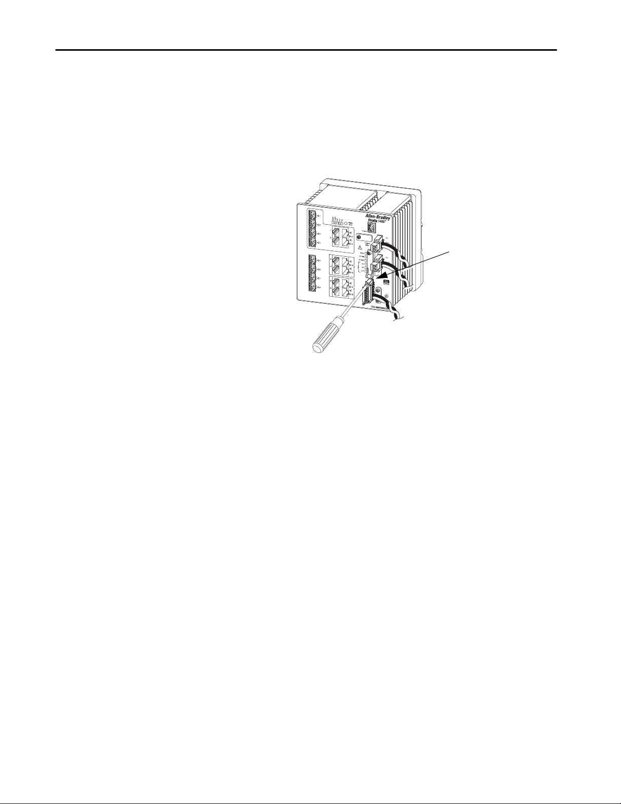
Install Stratix 5400 Switches Chapter 3
Attach the Alarm Relay Connector to the Switch
To attach the alarm relay connector to the front panel of the switch, follow
these steps.
1. Insert the alarm relay connector into the receptacle on the switch front
panel.
2. Use a ratcheting torque flathead screwdriver to tighten the captive
screws on the sides of the alarm relay connector.
Alarm Relay Connector
Upper Captive Screw
32563-M
Connect to 10/100 and 10/100/1000 Ports
The switch 10/100/1000 ports automatically configure themselves to operate
at the speed of attached devices. If the attached ports do not support
autonegotiation, you can explicitly set the speed and duplex parameters.
Connecting devices that do not autonegotiate or that have their speed and
duplex parameters that are manually set can reduce performance or result in no
linkage.
The Auto-MDIX feature is enabled by default. Unless this feature is disabled,
you can use either straight-through or crossover cables to connect to other
devices on the network.
To maximize performance, choose one of these methods for configuring the
Ethernet ports:
• Let the ports autonegotiate both speed and duplex
• Set the port speed and duplex parameters on both ends of the
connection
Rockwell Automation Publication 1783-UM007G-EN-P - February 2017 93
Page 94

Chapter 3 Install Stratix 5400 Switches
Connect to 10BASE-T, 100BASE-TX, or 1000BASE-T Ports
To connect to 10BASE-T, 100BASE-TX, or 1000BASE-T ports, follow these
steps.
ATTENTION: To prevent electrostatic-discharge (ESD) damage, follow
recommended board and component handling procedures.
1. Choose one of these options to connect a device:
• When connecting to workstations, servers, and routers, connect a
straight-through cable to an RJ45 connector on the front panel.
• When connecting to 1000BASE-T-compatible devices, use a twisted
four-pair, Category 5e or higher cable.
32564-M
2. Connect the other end of the cable to an RJ45 connector on the other
device.
The Port status indicator turns on when both the switch and the
connected device have an established link.
The Port status indicator is amber while Spanning Tree Protocol (STP)
discovers the topology and searches for loops. This can take up to 30
seconds, and then the Port status indicator turns green.
The following conditions can prevent the Port status indicator from
turning On:
• The device at the other end is not turned On.
• A problem exists with a cable or the adapter that is installed in the
attached device.
3. Reconfigure and restart the connected device if necessary.
4. Repeat this procedure to connect each device.
94 Rockwell Automation Publication 1783-UM007G-EN-P - February 2017
Page 95

Install Stratix 5400 Switches Chapter 3
Connect to PoE Ports
Switches with PoE ports require a separate power supply. For power supply
requirements based on your application, refer to
1. Insert a straight-through, twisted four-pair, Category 5e or better cable
with an RJ45 connector into the PoE port.
2. Insert the other cable end into an RJ45 connector on the other PoE
powered device.
page 83.
32565-M
Connect to SFP Module Ports
To connect a fiber-optic cable to an SFP module, follow these steps.
ATTENTION: Do not remove the rubber plugs from the SFP module port or
the rubber caps from the fiber-optic cable until you are ready to connect the
cable. The plugs and caps protect the SFP module ports and cables from
contamination and ambient light.
1. Remove the rubber plugs from the module port and fiber-optic cable,
and store them for future use.
2. Insert one end of the fiber-optic cable into the SFP module port.
3. Insert the other cable end into a fiber-optic receptacle on a target device.
4. Observe the port status indicator:
• The status indicator turns amber while the SFP discovers the
network topology and searches for loops. This process takes about 30
seconds, and then the port status indicator turns green.
• The status indicator turns green when the switch and the target
device have an established link.
• The status indicator turns off if the target device is not turned on or
there is a problem with the cable or the adapter that is installed in the
target device.
If necessary, reconfigure and restart the switch or the target device.
Rockwell Automation Publication 1783-UM007G-EN-P - February 2017 95
Page 96

Chapter 3 Install Stratix 5400 Switches
Connect to a Dual-purpose Port
A dual-purpose port is one port with two interfaces, one for an RJ45 cable and
another for an approved SFP module. Only one interface can be active at a
time. If both interfaces are connected, the SFP module has priority.
ATTENTION: Do not remove the rubber plugs from the SFP module port or
the rubber caps from the fiber-optic cable until you are ready to connect the
cable. The plugs and caps protect the SFP module ports and cables from
contamination and ambient light.
To connect to a dual-purpose port, follow these steps.
1. Connect an RJ45 connector to the 10/100/1000 port, or install an SFP
module into the SFP module slot, and connect a cable to the SFP
module port.
2. Connect the other end of the cable to the other device.
By default, the switch detects whether an RJ45 connector or SFP
module is connected to a dual-purpose port and configures the port
accordingly. You can change this setting and configure the port to
recognize only an RJ45 connector or only an SFP module by using the
media type interface configuration command.
96 Rockwell Automation Publication 1783-UM007G-EN-P - February 2017
Page 97

Install Stratix 5410 Switches
Topic Page
Switch Specifications 101
Power Supply Specifications 101
Overview 102
Parts List and Required Tools 103
Install or Remove the SD Card 105
Verify Switch Operation 107
Mount the Switch on a Rack 107
Mount the Switch on a Wall 111
Ground the Switch 114
Install a Power Supply Module in the Switch 115
Wire the Power Source 116
Remove a Power Supply Module from the Switch 120
Install an SFP Module 120
Remove an SFP Module from an SFP Slot 122
Wire the External Alarms 123
Attach the Alarm Relay Connector to the Switch 124
Connect to 10/100/1000 Ethernet, PoE/PoE+ Ports 124
Connect to SFP/SFP+ Ports 126
Chapter 4
ATTENTION: Environment and Enclosure
This equipment is intended for use in a Pollution Degree 2 industrial environment, in overvoltage Category II applications (as
defined in IEC 60664-1), at altitudes up to 2000 m (6562 ft) without derating.
This equipment is not intended for use in residential environments and may not provide adequate protection to radio
communication services in such environments.
This equipment is supplied as open-type equipment. It must be mounted within an enclosure that is suitably designed for those
specific environmental conditions that will be present and appropriately designed to prevent personal injury resulting from
accessibility to live parts. The enclosure must have suitable flame-retardant properties to prevent or minimize the spread of flame,
complying with a flame spread rating of 5VA or be approved for the application if nonmetallic. The interior of the enclosure must be
accessible only by the use of a tool. Subsequent sections of this publication may contain additional information regarding specific
enclosure type ratings that are required to comply with certain product safety certifications.
In addition to this publication, see the following:
• Industrial Automation Wiring and Grounding Guidelines, publication
1770-4.1, for additional installation requirements
• NEMA Standard 250 and IEC 60529, as applicable, for explanations of the degrees of protection provided by enclosures
Rockwell Automation Publication 1783-UM007G-EN-P - February 2017 97
Page 98

Chapter 4 Install Stratix 5410 Switches
North American Hazardous Location Approval
The following information applies when operating this equipment in
hazardous locations.
Products marked "CL I, DIV 2, GP A, B, C, D" are suitable for use in Class I Division 2 Groups
A, B, C, D, Hazardous Locations and nonhazardous locations only. Each product is
supplied with markings on the rating nameplate indicating the hazardous location
temperature code. When combining products within a system, the most adverse
temperature code (lowest "T" number) may be used to help determine the overall
temperature code of the system. Combinations of equipment in your system are subject
to investigation by the local Authority Having Jurisdiction at the time of installation.
Informations sur l’utilisation de cet équipement en environnements
dangereux.
Les produits marqués "CL I, DIV 2, GP A, B, C, D" ne conviennent qu'à une utilisation en
environnements de Classe I Division 2 Groupes A, B, C, D dangereux et non dangereux.
Chaque produit est livré avec des marquages sur sa plaque d'identification qui indiquent
le code de température pour les environnements dangereux. Lorsque plusieurs produits
sont combinés dans un système, le code de température le plus défavorable (code de
température le plus faible) peut être utilisé pour déterminer le code de température
global du système. Les combinaisons d'équipements dans le système sont sujettes à
inspection par les autorités locales qualifiées au moment de l'installation.
WARNING: EXPLOSION HAZARD
• Do not disconnect equipment unless power has
been removed or the area is known to be
nonhazardous.
• Do not disconnect connections to this
equipment unless power has been removed or
the area is known to be nonhazardous. Secure
any external connections that mate to this
equipment by using screws, sliding latches,
threaded connectors, or other means provided
with this product.
• Substitution of components may impair
suitability for Class I, Division 2.
• If this product contains batteries, they must
only be changed in an area known to be
nonhazardous.
North American Zones:
UL 60079-0, 5th Ed, 2009-10-21l; UL 60079-15, 3rd Ed, 2009-7-17;
CAN/CSA C22.2 No. 60079-15-12 Ed. 1; CAN/CSA C22.2 No. 60079-0-11 Ed. 2
WARNING: RISQUE D’EXPLOSION
• Couper le courant ou s'assurer que
l'environnement est classé non dangereux
avant de débrancher l'équipement.
• Couper le courant ou s'assurer que
l'environnement est classé non dangereux
avant de débrancher les connecteurs. Fixer tous
les connecteurs externes reliés à cet
équipement à l'aide de vis, loquets coulissants,
connecteurs filetés ou autres moyens fournis
avec ce produit.
• La substitution de composants peut rendre cet
équipement inadapté à une utilisation en
environnement de Classe I, Division 2.
• S'assurer que l'environnement est classé non
dangereux avant de changer les piles.
European Hazardous Location Approval
The following applies to products marked II 3 G: Such modules:
• Are Equipment Group II, Equipment Category 3, and comply with the Essential Health and Safety Requirements relating to the design and construction of such equipment given
in Annex II to Directive 94/9/EC. See the EC Declaration of Conformity at
• The type of protection is “Ex nA nC IIC T4 Gc” according to EN 60079-15.
• Comply to Standards EN 60079-0:2012+A11:2013, EN 60079-15:2010, reference certificate number DEMKO15ATEX1492X.
• Are intended for use in areas in which explosive atmospheres caused by gases, vapors, mists, or air are unlikely to occur, or are likely to occur only infrequently and for short
periods. Such locations correspond to Zone 2 classification according to ATEX directive 1999/92/EC.
98 Rockwell Automation Publication 1783-UM007G-EN-P - February 2017
http://www.rockwellautomation.com/products/certification for details.
Page 99

Install Stratix 5410 Switches Chapter 4
WARNING: Special Conditions for Safe Use
• This equipment shall be mounted in an ATEX Zone 2 certified enclosure with a minimum ingress protection rating of at least
IP54 (as defined in EN 60529) and used in an environment of not more than Pollution Degree 2 (as defined in EN 60664-1)
when applied in Zone 2 environments. The enclosure must be accessible only by the use of a tool.
• This equipment shall be used within its specified ratings defined by Rockwell Automation.
• Provision shall be made to prevent the rated voltage from being exceeded by transient disturbances of more than 140% of the
rated voltage when applied in Zone 2 environments.
• Secure any external connections that mate to this equipment by using screws, sliding latches, threaded connectors, or other
means provided with this product.
• Do not disconnect equipment unless power has been removed or the area is known to be nonhazardous.
• The USB port is intended for temporary local programming purposes only and not intended for permanent connection. Do not
use the USB port in hazardous locations.
WARNING: If you connect or disconnect the communication cable with power applied to this module or any device on the
network, an electrical arc can occur. This could cause an explosion in hazardous location installations.
Be sure that power is removed or the area is nonhazardous before proceeding.
WARNING: Use supply wires suitable for 30 °C (86 °F) above surrounding ambient.
WARNING: When used in a Class I, Division 2, hazardous location, this equipment must be mounted in a suitable enclosure with
proper wiring method that complies with the governing electrical codes.
WARNING: If you connect or disconnect wiring while the field-side power is on, an electrical arc can occur. This could cause an
explosion in hazardous location installations.
Be sure that power is removed or the area is nonhazardous before proceeding.
WARNING: When you insert or remove the CompactFlash/SD memory Card while power is on, an electrical arc can occur. This
could cause an explosion in hazardous location installations.
Be sure that power is removed or the area is nonhazardous before proceeding.
WARNING: When you insert or remove the small form-factor pluggable (SFP) optical transceiver while power is on, an electrical
arc can occur. This could cause an explosion in hazardous location installations.
Be sure that power is removed or the area is nonhazardous before proceeding.
WARNING: Do not use the USB port in hazardous locations.
Rockwell Automation Publication 1783-UM007G-EN-P - February 2017 99
Page 100

Chapter 4 Install Stratix 5410 Switches
ATTENTION: Prevent Electrostatic Discharge
This equipment is sensitive to electrostatic discharge, which can cause internal damage and affect normal operation. Follow these
guidelines when you handle this equipment:
• Touch a grounded object to discharge potential static.
• Wear an approved grounding wriststrap.
• Do not touch connectors or pins on component boards.
• Do not touch circuit components inside the equipment.
• Use a static-safe workstation, if available.
• Store the equipment in appropriate static-safe packaging when not in use.
ATTENTION: The USB port is intended for temporary local programming purposes only and not intended for permanent
connection. The USB cable is not to exceed 3.0 m (9.84 ft) and must not contain hubs.
ATTENTION: This product is grounded through the DIN rail to chassis ground. Use zinc-plated yellow-chromate steel DIN rail to
assure proper grounding. The use of other DIN rail materials (for example, aluminum or plastic) that can corrode, oxidize, or are
poor conductors, can result in improper or intermittent grounding. Secure DIN rail to mounting surface approximately every 200
mm (7.8 in.) and use end-anchors appropriately.
ATTENTION: Under certain conditions, viewing the optical port may expose the eye to hazard. When viewed under some
conditions, the optical port may expose the eye beyond the maximum permissible exposure recommendations.
ATTENTION: Class 1 laser product. Laser radiation is present when the system is open and interlocks bypassed. Only trained and
qualified personnel should be allowed to install, replace, or service this equipment.
ATTENTION: If this equipment is used in a manner not specified by the manufacturer, the protection provided by the equipment
may be impaired.
ATTENTION: Read this document and the documents listed in the additional resources section about installation, configuration,
and operation of this equipment before you install, configure, operate, or maintain this product. Users are required to familiarize
themselves with installation and wiring instructions in addition to requirements of all applicable codes, laws, and standards.
ATTENTION: Activities including installation, adjustments, putting into service, use, assembly, disassembly, and maintenance
are required to be carried out by suitably trained personnel in accordance with applicable code of practice.
In case of malfunction or damage, no attempts at repair should be made. The module should be returned to the manufacturer for
repair. Do not dismantle the module.
ATTENTION: This equipment is certified for use only within the surrounding air temperature range of -40…60 °C
(-40…140 °F). The equipment must not be used outside of this range.
100 Rockwell Automation Publication 1783-UM007G-EN-P - February 2017
 Loading...