

Page 1

Programming Manual
Logix5000 Controllers Messages
Catalog Numbers
1789-L60, 1794-L34, PowerFlex 700S/SE
1756-L1, 1756-L55, 1756-L61, 1756-L62, 1756-L63, 1769-L31, 1769-L32C, 1769-L32E, 1769-L35CR, 1769-L35E,
Page 2
Important User Information
Solid-state equipment has operational characteristics differing from those of electromechanical equipment. Safety
Guidelines for the Application, Installation and Maintenance of Solid State Controls (publication
your local Rockwell Automation sales office or online at
http://www.rockwellautomation.com/literature/) describes some
important differences between solid-state equipment and hard-wired electromechanical devices. Because of this difference,
and also because of the wide variety of uses for solid-state equipment, all persons responsible for applying this equipment
must satisfy themselves that each intended application of this equipment is acceptable.
In no event will Rockwell Automation, Inc. be responsible or liable for indirect or consequential damages resulting from
the use or application of this equipment.
The examples and diagrams in this manual are included solely for illustrative purposes. Because of the many variables and
requirements associated with any particular installation, Rockwell Automation, Inc. cannot assume responsibility or
liability for actual use based on the examples and diagrams.
No patent liability is assumed by Rockwell Automation, Inc. with respect to use of information, circuits, equipment, or
software described in this manual.
Reproduction of the contents of this manual, in whole or in part, without written permission of Rockwell Automation,
Inc., is prohibited.
Throughout this manual, when necessary, we use notes to make you aware of safety considerations.
WARNING: Identifies information about practices or circumstances that can cause an explosion in a hazardous environment, which may
lead to personal injury or death, property damage, or economic loss.
SGI-1.1 available from
ATTENTION: Identifies information about practices or circumstances that can lead to personal injury or death, property damage, or
economic loss. Attentions help you identify a hazard, avoid a hazard, and recognize the consequence
SHOCK HAZARD: Labels may be on or inside the equipment, for example, a drive or motor, to alert people that dangerous voltage may be
present.
BURN HAZARD: Labels may be on or inside the equipment, for example, a drive or motor, to alert people that surfaces may reach
dangerous temperatures.
IMPORTANT
Allen-Bradley, Rockwell Automation, Logix5000, RSLogix 5000, ControlLogix, GuardLogix, CompactLogix, PowerFlex, SoftLogix, Rockwell Software, PLC-2, PLC-3, PLC-5, SLC, SLC 500, and TechConnect are
trademarks of Rockwell Automation, Inc.
Trademarks not belonging to Rockwell Automation are property of their respective companies.
Identifies information that is critical for successful application and understanding of the product.
Page 3

Summary of Changes
This manual contains new and updated information. Changes throughout this
revision are marked by change bars, as shown to the right of this paragraph.
New and Updated Information
This table contains the changes made to this revision.
Topic Page
Added information on the Large Connection checkbox to second footnote under
table.
Added a new row to the table that discusses “If the MSG instructions are to” —
New row starts with “Same device and cached and large connection”.
Added additional information to the example given for Share a Connection.
Changed Destination to Destination Element to reflect changes to the UI.
Updated instructions on setting the path to a remote controller.
Updated the screen shot to reflect changes to the UI.
Changed Destination Tag to Destination Element and Source Tag to Source
Element to reflect changes to the UI.
11
12
12
14
27
30
30
Rockwell Automation Publication 1756-PM012D-EN-P - November 2011 3
Page 4

Summary of Changes
Notes:
4 Rockwell Automation Publication 1756-PM012D-EN-P - November 2011
Page 5

Table of Contents
Summary of Changes
Table of Contents
Preface
Controller Messages
Manage Multiple Messages
New and Updated Information. . . . . . . . . . . . . . . . . . . . . . . . . . . . . . . . . . . . . 3
Purpose of This Manual. . . . . . . . . . . . . . . . . . . . . . . . . . . . . . . . . . . . . . . . . . . . 7
Additional Resources . . . . . . . . . . . . . . . . . . . . . . . . . . . . . . . . . . . . . . . . . . . . . . 7
Chapter 1
Introduction . . . . . . . . . . . . . . . . . . . . . . . . . . . . . . . . . . . . . . . . . . . . . . . . . . . . . . 9
Supported Data Types . . . . . . . . . . . . . . . . . . . . . . . . . . . . . . . . . . . . . . . . . 9
Message Queue. . . . . . . . . . . . . . . . . . . . . . . . . . . . . . . . . . . . . . . . . . . . . . . . . . . 10
Cache List . . . . . . . . . . . . . . . . . . . . . . . . . . . . . . . . . . . . . . . . . . . . . . . . . . . . . . . 11
Unconnected Buffers . . . . . . . . . . . . . . . . . . . . . . . . . . . . . . . . . . . . . . . . . . . . . 12
Guidelines . . . . . . . . . . . . . . . . . . . . . . . . . . . . . . . . . . . . . . . . . . . . . . . . . . . . . . . 13
Get or Set the Number of Unconnected Buffers. . . . . . . . . . . . . . . . . . . . . 13
Get the Number of Unconnected Buffers . . . . . . . . . . . . . . . . . . . . . . . 14
Set the Number of Unconnected Buffers . . . . . . . . . . . . . . . . . . . . . . . 14
Convert Between INTs and DINTs . . . . . . . . . . . . . . . . . . . . . . . . . . . . . . . 16
Chapter 2
Introduction . . . . . . . . . . . . . . . . . . . . . . . . . . . . . . . . . . . . . . . . . . . . . . . . . . . . . 19
Message Manager Logic . . . . . . . . . . . . . . . . . . . . . . . . . . . . . . . . . . . . . . . . . . . 19
Initialize the Logic . . . . . . . . . . . . . . . . . . . . . . . . . . . . . . . . . . . . . . . . . . . . 20
Restart the Sequence . . . . . . . . . . . . . . . . . . . . . . . . . . . . . . . . . . . . . . . . . . 20
Send the First Group of MSGs. . . . . . . . . . . . . . . . . . . . . . . . . . . . . . . . . 20
Enable the Second Group of MSGs. . . . . . . . . . . . . . . . . . . . . . . . . . . . . 21
Send the Second Group of MSGs . . . . . . . . . . . . . . . . . . . . . . . . . . . . . . 21
Enable the Next Group of MSGs. . . . . . . . . . . . . . . . . . . . . . . . . . . . . . . 21
Send the Next Group of MSGs . . . . . . . . . . . . . . . . . . . . . . . . . . . . . . . . 22
Send a Message to Multiple
Controllers
Index
Chapter 3
Introduction . . . . . . . . . . . . . . . . . . . . . . . . . . . . . . . . . . . . . . . . . . . . . . . . . . . . . 23
Set Up the I/O Configuration. . . . . . . . . . . . . . . . . . . . . . . . . . . . . . . . . . . . . 24
Define Your Source and Destination Elements. . . . . . . . . . . . . . . . . . . . . . 24
Create the MESSAGE_ CONFIGURATION Data Type. . . . . . . . . . . 25
Create the Configuration Array . . . . . . . . . . . . . . . . . . . . . . . . . . . . . . . . . . . 26
Get the Size of the Local Array . . . . . . . . . . . . . . . . . . . . . . . . . . . . . . . . . . . . 28
Load the Message Properties for a Controller . . . . . . . . . . . . . . . . . . . . . . . 29
Configure the Message. . . . . . . . . . . . . . . . . . . . . . . . . . . . . . . . . . . . . . . . . . . . 30
Step to the Next Controller . . . . . . . . . . . . . . . . . . . . . . . . . . . . . . . . . . . 31
Restart the Sequence . . . . . . . . . . . . . . . . . . . . . . . . . . . . . . . . . . . . . . . . . . 31
Rockwell Automation Publication 1756-PM012D-EN-P - November 2011 5
Page 6

Table of Contents
Notes:
6 Rockwell Automation Publication 1756-PM012D-EN-P - November 2011
Page 7

Preface
Purpose of This Manual
Additional Resources
This manual shows how to program message (MSG) instructions to and from
Logix5000 controllers. This manual is one of a set of related manuals that show
common procedures for programming and operating Logix5000 controllers.
For a complete list of common procedures manuals, see the
Logix5000 Controllers Common Procedures Programming Manual, publication
1756-PM001.
The term Logix5000 controller refers to any controller that is based on the
Logix5000 operating system, such as:
• CompactLogix controllers.
• ControlLogix controllers.
• DriveLogix controllers.
• FlexLogix controllers.
• SoftLogix5800 controllers.
These documents contain additional information concerning related products
from Rockwell Automation.
Resource Description
Industrial Automation Wiring and Grounding Guidelines,
publication
Product Certifications website,
1770-4.1
http://www.ab.com Provides declarations of conformity, certificates, and
You can view or download publications at
Provides general guidelines for installing a Rockwell
Automation industrial system.
other certification details.
http://www.rockwellautomation.com/
literature/. To order paper copies of technical documentation, contact your local
Allen-Bradley distributor or Rockwell Automation sales representative.
Rockwell Automation Publication 1756-PM012D-EN-P - November 2011 7
Page 8

Preface
Notes:
8 Rockwell Automation Publication 1756-PM012D-EN-P - November 2011
Page 9
Controller Messages
Chapter 1
Introduction
This section describes how to transfer data between controllers (send or receive
data) by executing a message (MSG) instruction. Cache connections and buffers
are explained so you can correctly program the controller.
Supported Data Types
The following data types are supported when sending CIP messages:
• SINT
• INT
• DINT
• LINT
• REAL
In addition, any structure type that is predefined, module-defined, or userdefined can be used for sending a message.
See
page 16 for more information on INTs and DINTs.
For complete details on programming a message instruction, see the Logix5000
Controllers General Instruction Reference Manual,
publication
1756-RM003.
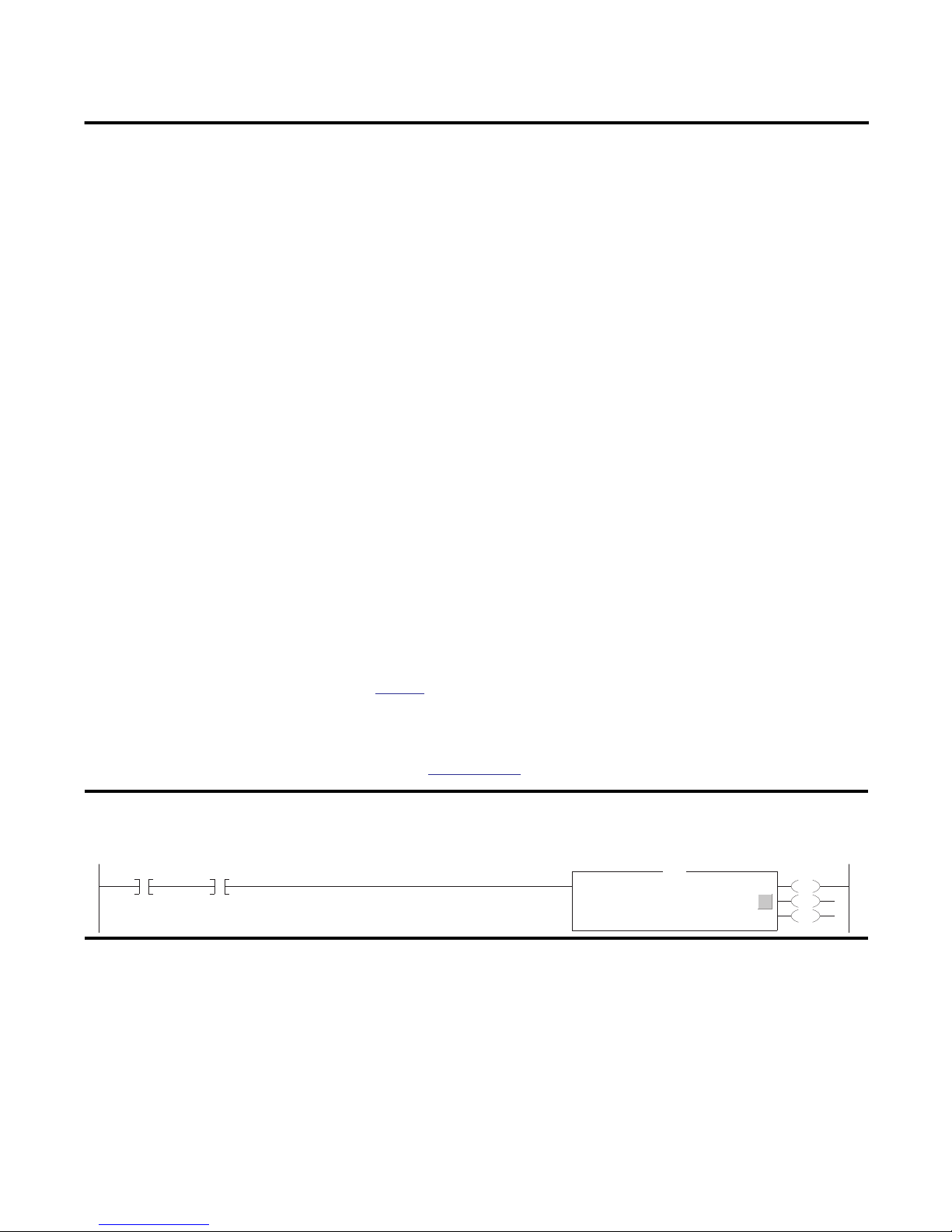
EXAMPLE
If count_send = 1 and count_msg.EN = 0 (MSG instruction is not already enabled), then execute a MSG instruction that sends data to another controller.
count_send/count_msg.en
Execute a Message (MSG) Instruction
Type - Unconfigured
MSG
Message Controlcount_msg
Rockwell Automation Publication 1756-PM012D-EN-P - November 2011 9
...
EN
DN
ER
Page 10
Chapter 1 Controller Messages
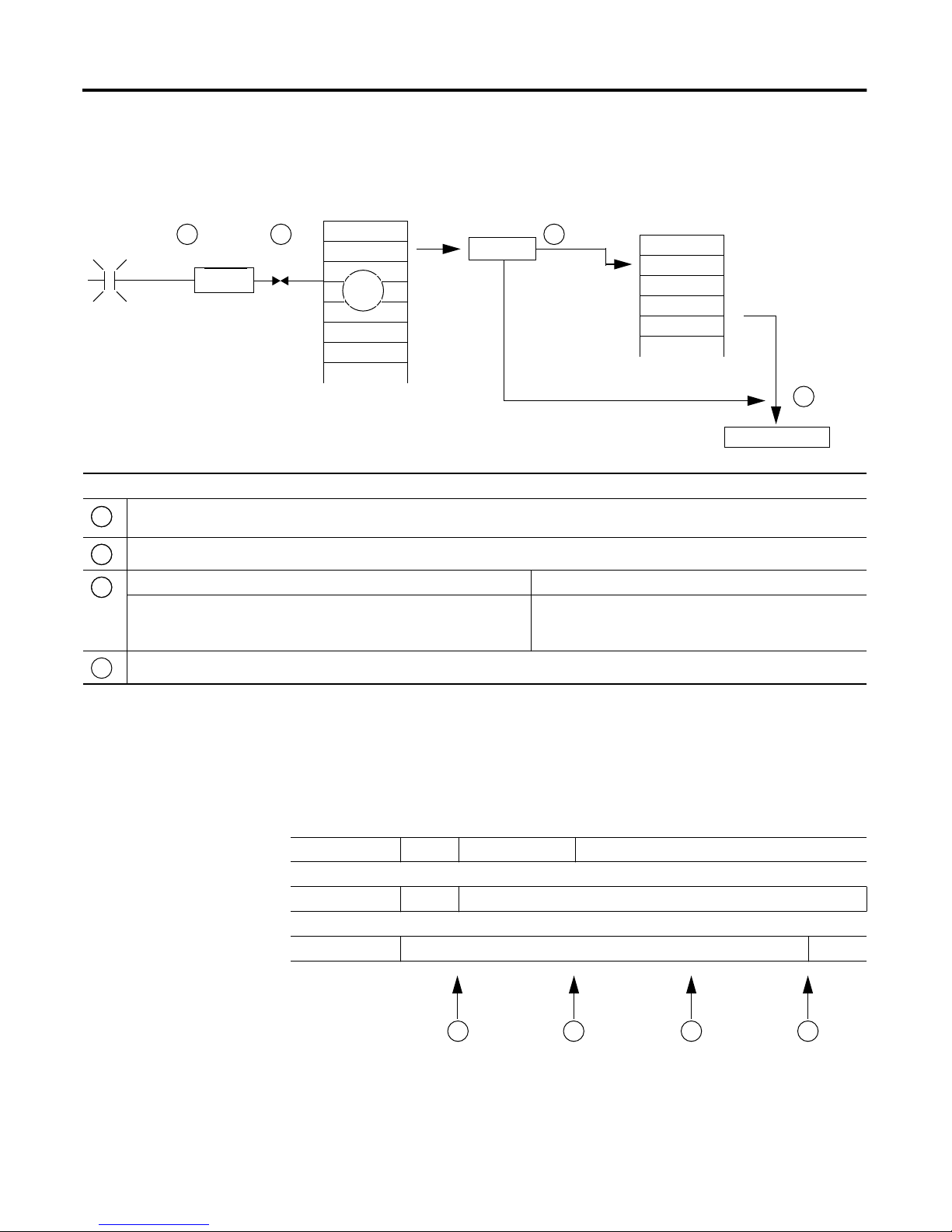
This diagram shows how the controller processes MSG instructions.
Message Queue
1 2
Throttle
MSG
16
Description
The controller scans the MSG instruction and its rung-condition-in goes true. The message will pass to a throttle, which has 16 positions. If the throttle is full, the message
1
will stay enabled but is held until another controller scan.
The System-overhead time slice executes and the message is pulled from the throttle to the message queue.
2
If the MSG instruction Then the MSG instruction
3
Does not use a connection or the connection was not previously cached.
Uses a connection and the connection is cached
Communication occurs with the destination device.
4
48
total
Cache List
3
Cached?
No
Yes
Uses an unconnected buffer to establish communication with the
destination device.
Does not use an unconnected buffer.
Unconnected Outgoing
Buffers (10 to 40)
Destination Device
4
Message Queue
The message queue holds up to 48 MSG instructions, including those that you
configure as a block-transfer read or block-transfer write. When the queue is full,
an instruction tries to enter the queue on each subsequent scan of the instruction,
as shown below.
Rung-condition-in false true false
.EN bit off on
.EW bit off on
1 2 3 4
10 Rockwell Automation Publication 1756-PM012D-EN-P - November 2011
Page 11

Description
1
2 3
& The controller scans the MSG instruction.
4
The controller scans the MSG instruction.
The rung-condition-in for the MSG instruction is true.
The EN bit is set.
The MSG instruction attempts to enter the queue but there are 16 throttle positions. If all 16 are filled and a 17th message is executed, the message
goes enabled, but ...
...the EW bit remains cleared.
The rung-condition-in for the MSG instruction is false.
The EN bit remains set.
The MSG instruction attempts to pass through the throttle, but there are no open positions yet.
The EW bit remains cleared.
The controller scans the MSG instruction.
The MSG instruction attempts to enter the queue. This time the throttle position is open and the message can pass to the message queue.
The EW bit is set.
Controller Messages Chapter 1
Cache List
Depending on how you configure a MSG instruction, it may use a connection to
send or receive data.
This type of message And this communication method Uses a connection
CIP data table read or write Your option
PLC-2, PLC-3, PLC-5, or SLC (all types) CIP
CIP with Source ID
DH+ Yes
CIP generic Your option
Block-transfer read or write Yes
(1) CIP data table read or write messages can be connected or unconnected. But, for most applications, we recommend you leave CIP data table read or write
messages connected.
(2) CIP generic messages can be connected or unconnected. But for most applications, we recommend you leave CIP generic messages unconnected, unless you want
to use the Large Connection option.
No
(1)
(2)
If a MSG instruction uses a connection, you have the option to leave the
connection open (cache) or close the connection when the message is done
transmitting.
If you Then
Cache the connection The connection stays open after the MSG instruction is done. This optimizes
Do not cache the connection The connection closes after the MSG instruction is done. This frees up that
execution time. Opening a connection each time the message executes increases
execution time.
connection for other uses.
Rockwell Automation Publication 1756-PM012D-EN-P - November 2011 11
Page 12

Chapter 1 Controller Messages
The controller has these limits on the number of connections that you can cache:
If you have this software and
firmware revision
11.x or earlier • Block transfer messages for up to 16 connections
12.x or later Up to 32 connections
Then you can cache
• Other types of messages for up to 16 connections
If several messages go to the same device, the messages may be able to share a
connection.
If the MSG instructions are to And they are Then
Different devices Each MSG instruction uses 1 connection.
Same device and cached and not large connection Enabled at the same time (same scan) Each MSG instruction uses 1 connection and 1 cached
Not enabled at the same time All MSG instructions use 1 connection and 1 cached buffer.
Same device and cached and large connection Enabled at the same time (same scan) Each MSG instruction uses 1 connection and 1 cached
Not enabled at the same time All MSG instructions use 1 connection and 1 cached buffer.
EXAMPLE
Share a Connection.
buffer.
They share the connection and the buffer.
buffer.
They share the connection and the buffer.
• If the controller alternates between sending a block-transfer read message and a block-transfer write
message to the same module, then together both messages count as one connection. Caching both
messages counts as one on the cached buffer.
• If the controller sends 10 cached connected messages to the same bridge module (e.g. 1756-EN2T)
where 7 utilize a standard connection (large connection unchecked) and 3 utilize a large connection,
then the 7 standard connection messages all utilize one cached connection. The 3 large connection
messages all utilize another cached connection. In total, the 10 messages utilize 2 separate cached
connections.
Unconnected Buffers
Term Definition
Unconnected buffer An allocation of memory that the controller uses to process unconnected communication. The controller performs
12 Rockwell Automation Publication 1756-PM012D-EN-P - November 2011
To establish a connection or process unconnected messages, the controller uses an
unconnected buffer.
unconnected communication when it:
• establishes a connection with a device, including an I/O module.
• executes a MSG instruction that does not use a connection.
The controller can have 10… 40 unconnected buffers.
• The default number is 10.
• To increase the number of unconnected buffers, execute a MSG instruction that reconfigures the number of
unconnected buffers.
• Each unconnected buffer uses 1.2 KB of memory.
• If all the unconnected buffers are in use when an instruction leaves the message queue, the instruction errors and
data does not transfer.
Page 13

Controller Messages Chapter 1
If a MSG instruction uses a connection, the instruction uses an unconnected
buffer when it first executes to establish a connection. If you configure the
instruction to cache the connection, it no longer requires an unconnected buffer
once the connection is established.
Guidelines
Guideline Details
1. For each MSG instruction, create a control tag. Each MSG instruction requires its own control tag.
2. Keep the source and/or destination data at the controller
scope.
3. If your MSG is to a device that uses 16-bit integers, use a
buffer of INTs in the MSG and DINTs throughout the project.
4. Cache the connected MSGs that execute most frequently. Cache the connection for those MSG instructions that execute most frequently, up to the maximum number
5. If you want to enable more than 16 MSGs at one time, use
some type of management strategy.
6. Keep the number of unconnected and uncached MSGs less
than the number of unconnected buffers.
As you plan and program your MSG instructions, follow these guidelines.
• Data type = MESSAGE
• Scope = controller
• The tag cannot be part of an array or a user-defined data type.
A MSG instruction can access only tags that are in the Controller Tags folder (controller scope).
If your message is to a device that uses 16-bit integers, such as a PLC-5 or SLC 500 controller, and it transfers integers
(not REALs), use a buffer of INTs in the message and DINTs throughout the project.
This increases the efficiency of your project because Logix5000 controllers execute more efficiently and use less
memory when working with 32-bit integers (DINTs).
page 16.
See
permissible for your controller revision.
This optimizes execution time because the controller does not have to open a connection each time the message
executes.
If you enable more than 16 MSGs at one time, some MSG instructions may experience delays in entering the queue.
To guarantee the execution of each message, use one of these options:
• Enable each message in sequence.
• Enable the messages in groups.
• Program a message to communicate with multiple devices.
• Program logic to coordinate the execution of messages.
The controller can have 10…40 unconnected buffers. The default number is 10.
• If all the unconnected buffers are in use when an instruction leaves the message queue, the instruction errors
and does not transfer the data.
• You can increase the number of unconnected buffers (40 max), but continue to follow guideline
• To increase the number of unconnected buffers, see page 13.
5.
Get or Set the Number of
Unconnected Buffers
To determine or change the number of unconnected buffers, use a MSG
instruction.
• The range is 10…40 unconnected buffers.
• The default number is 10.
• Each unconnected buffers uses 1.1 KB of memory.
Rockwell Automation Publication 1756-PM012D-EN-P - November 2011 13
Page 14

Chapter 1 Controller Messages
Get the Number of Unconnected Buffers
To determine the number of unconnected buffers that the controller currently
has available, configure a Message (MSG) instruction as follows.
On this tab For this item Type or select
Configuration Message Type CIP Generic
Service Type Custom
Service Code 3
Class 304
Instance 1
Attribute 0
Source Element source_array where data type = SINT[4]
In this element Enter
source_array[0] 1
source_array[1] 0
source_array[2] 17
source_array[3] 0
Source Length (bytes) 4 (Write 4 SINTs.)
Destination Element destination_array where data type = SINT[10] (Leave all the values = 0.)
destination_array[6] = current number of unconnected buffers
Communication Path 1, slot_number_of_controller
Set the Number of Unconnected Buffers
As a starting value, set the number of unconnected buffers equal to the number of
unconnected and uncached messages enabled at one time plus approximately 5.
The additional 5 buffers provide a cushion in case you underestimate the number
of messages that are enabled at one time.
14 Rockwell Automation Publication 1756-PM012D-EN-P - November 2011
Page 15

To change the number of unconnected buffers of the controller, configure a
Message (MSG) instruction as follows.
On this tab For this item Type or select
Configuration Message Type CIP Generic
Service Type Custom
Service Code 4
Class 304
Instance 1
Attribute 0
Source Element source_array where data type = SINT[8]
In this element Enter
source_array[0] 1
source_array[1] 0
source_array[2] 17
source_array[3] 0
source_array[4] Number of unconnected buffers that you want.
source_array[5] 0
source_array[6] 0
source_array[7] 0
Source Length (bytes) 8 (Write 8 SINTs.)
Destination Element destination_array where data type = SINT[6] (Leave all the values = 0.)
Communication Path 1, slot_number_of_controller
Controller Messages Chapter 1
Rockwell Automation Publication 1756-PM012D-EN-P - November 2011 15
Page 16

Chapter 1 Controller Messages
EXAMPLE
Set the Number of Unconnected Buffers
If S:FS = 1 (first scan), then set the number of unconnected buffers for the controller.
Source_Array[0] = 1
Source_Array[1] = 0
Source_Array[2] = 17
Source_Array[3] = 0
Source_Array[4] = 12 (The number of unconnected buffers that you want. In this example, we want 12 buffers.)
If UCB_Set.EN = 0 (MSG instruction is not already enabled) then
MSG instruction sets the number of unconnected buffers = Source_Array[4].
Tag Name Type Description
UCB_Set MESSAGE Control tag for the MSG instruction.
Source_Array SINT[8] Source values for the MSG instruction, including the number of unconnected buffers that you want.
Convert Between INTs
and DINTs
16 Rockwell Automation Publication 1756-PM012D-EN-P - November 2011
In the Logix5000 controller, use the DINT data type for integers whenever
possible. Logix5000 controllers execute more efficiently and use less memory
when working with 32-bit integers (DINTs).
If your message is to a device that uses 16-bit integers, such as a PLC-5 or
SLC 500 controller, and it transfers integers (not REALs), use a buffer of INTs in
Page 17

Controller Messages Chapter 1
the message and DINTs throughout the project. This increases the efficiency of
your project.
Read 16-Bit Integers Data from the
device
Word 1
Word 2
Word 3
1
Buffer of INTs DINTs for use in the
INT_Buffer[0] DINT_Array[0]
INT_Buffer[1] DINT_Array[1]
INT_Buffer[2] DINT_Array[2]
2
project
1. The Message (MSG) instruction reads 16-bit integers (INTs) from the
device and stores them in a temporary array of INTs.
2. An File Arith/Logical (FAL) instruction converts the INTs to DINTs for
use by other instructions in your project.
1
Write 16-Bit Integers DINTs from the project Buffer of INTs Data for the
2
device
DINT_Array[0] INT_Buffer[0] Word 1
DINT_Array[1] INT_Buffer[1] Word 2
DINT_Array[2] INT_Buffer[2] Word 3
1. An FAL instruction converts the DINTs from the Logix5000 controller to
INTs.
2. The MSG instruction writes the INTs from the temporary array to the
device.
EXAMPLE
If Condition_1 = 1 And Msg_1.EN = 0 (MSG instruction is not already enabled) then
read 3 integers from the PLC-5 controller and store them in INT_Buffer (3 INTs).
If Msg_1.DN =1 (MSG instruction has read the data.) then
reset the FAL instruction.
Read integer values from a PLC-5 controller
Rockwell Automation Publication 1756-PM012D-EN-P - November 2011 17
Page 18

Chapter 1 Controller Messages
The FAL instruction sets DINT_Array = INT_Buffer. This converts the values to 32-bit integers (DINTs).
EXAMPLE
If Condition_2 = 1 then
reset the FAL instruction.
The FAL instruction sets INT_Buffer = DINT_Array. This converts the values to 16-bit integers (INTs).
If Control_2.DN = 1 (FAL instruction has converted the DINTs to INTs)
and Msg_2.EN = 0 (MSG instruction is not already enabled) then
write the integers in INT_Buffer (3 INTs) to the PLC-5 controller.
Write integer values to a PLC-5 controller.
18 Rockwell Automation Publication 1756-PM012D-EN-P - November 2011
Page 19

Manage Multiple Messages
Chapter 2
Introduction
Message Manager Logic
You can use ladder logic to send groups of message (MSG) instructions in
sequence.
• To be processed, each MSG instruction must enter the message queue.
• The queue holds 48 MSGs.
• If more than 16 MSGs are enabled at one time, the message throttle will
prevent some of the messages from being able to be placed into the message
queue.
• If this occurs, the MSG has to wait until there is room on the queue before
the controller can process the MSG. On each subsequent scan of the MSG,
it checks the queue to see if there is room.
The message manager logic lets you control the number of MSGs that are enabled
at one time and enable subsequent MSGs in sequence. In this way, MSGs enter
and exit the queue in an ordered fashion and do not have to wait for room on the
queue to become available.
The message manager logic sends three groups of MSGs.
• To make the example in this section easier to follow, each groups contains
only two MSGs.
• In your project, use more MSGs in each group, such as five.
• Use as many groups as needed to include all your MSGs.
The Msg_Group tag controls the enabling of each MSG.
• The tag uses the DINT data type.
• Each bit of the tag corresponds to a group of MSGs.
• For example, Msg_Group.0 enables and disables the first group of MSGs
(group 0).
Rockwell Automation Publication 1756-PM012D-EN-P - November 2011 19
Page 20

Chapter 2 Manage Multiple Messages
If S:FS = 1 (first scan), then initialize the MSGs:
Msg_Group = 0, which disables all the MSGs.
Msg_Group.0 =1, which enables the first group of MSGs.
If the MSGs in group 2 (last group) are currently enabled (Msg_Group.2 = 1)
and Msg_4 is done or errored
and Msg_5 is done or errored
then restart the sequence of MSGs with the first group:
Msg_Group.2 = 0. This disables the last group of MSGs.
Msg_Group.0 = 1. This enables the first group of MSGs.
Initialize the Logic
Restart the Sequence
Send the First Group of MSGs
If Msg_Group.0 changes from 0 -> 1 then
send Msg_0.
send Msg_1.
Because a MSG instruction is a transitional instruction, it executes only when its rung-condition-in changes from
false to true.
20 Rockwell Automation Publication 1756-PM012D-EN-P - November 2011
Page 21

Enable the Second Group of MSGs
If the MSGs in group 0 are currently enabled (Msg_Group.0 = 1)
and Msg_0 is done or errored
and Msg_1 is done or errored
then
Msg_Group.0 = 0. This disables the current group of MSGs.
Msg_Group.1 = 1. This enables the next group of MSGs.
Send the Second Group of MSGs
If Msg_Group.1 changes from 0 -> 1 then
send Msg_2.
send Msg_3.
Manage Multiple Messages Chapter 2
If the MSGs in group 1 are currently enabled (Msg_Group.1 = 1)
and Msg_2 is done or errored
and Msg_3 is done or errored
then
Msg_Group.1 = 0. This disables the current group of MSGs.
Msg_Group.2 = 1. This enables the next group of MSGs.
Enable the Next Group of MSGs
Rockwell Automation Publication 1756-PM012D-EN-P - November 2011 21
Page 22

Chapter 2 Manage Multiple Messages
If Msg_Group.1 changes from 0 -> 1 then
send Msg_2.
send Msg_3.
Send the Next Group of MSGs
22 Rockwell Automation Publication 1756-PM012D-EN-P - November 2011
Page 23

Send a Message to Multiple Controllers
Chapter 3
Introduction
43052
You can program a single message instruction to communicate with multiple
controllers. To reconfigure a MSG instruction during runtime, write new values
to the members of the MESSAGE data type.
IMPORTANT
A B
In the MESSAGE data type, the RemoteElement member stores the tag name or address of the data in the
controller that receives the message.
If the message Then the RemoteElement is the
Reads data Source element
Writes data Destination element
Tag Name
message
−
message.RemoteElement.
+
message.RemoteIndex.
+
message.LocalIndex.
+
message.Channel.
+
message.Rack.
+
message.Group.
+
message.Slot.
+
message.Path.
+
A. If you use an asterisk [*] to designate the element number of the array,
the value in provides the element number.
B
B. The Index box is available only when you use an asterisk [*] in the
Source Element or Destination Element. The instruction substitutes
the value of Index for the asterisk [*].
Rockwell Automation Publication 1756-PM012D-EN-P - November 2011 23
Page 24

Chapter 3 Send a Message to Multiple Controllers
You need to complete the following to send a message to multiple controllers:
•
Set Up the I/O Configuration
•
Define Your Source and Destination Elements
Create the MESSAGE_ CONFIGURATION Data Type
•
•
Create the Configuration Array
•
Get the Size of the Local Array
Load the Message Properties for a Controller
•
•
Configure the Message
•
Step to the Next Controller
•
Restart the Sequence
TIP
Set Up the I/O Configuration
To copy the above components from a sample project, open the
…\RSLogix 5000\Projects\Samples folder.
MSG_to_Multiple_Controllers.ACD
43055
Open this project.
Although not required, we recommend that you add the communication
modules and remote controllers to the I/O configuration of the controller. This
makes it easier to define the path to each remote controller.
For example, once you add the local communication module, the remote
communication module, and the destination controller, clicking Browse lets you
select the destination.
Message Path Browser
Path: peer_controller
peer_controller
I/O Configuration
−
Define Your Source and Destination
Elements
24 Rockwell Automation Publication 1756-PM012D-EN-P - November 2011
[0] 1756-CNB/x Local_CNB
−
2 [0] 1756-CNB/x chassis_b
−
[1] 1756-L55/x peer_controller
In this procedure, an array stores the data that is read from or written to each
remote controller. Each element in the array corresponds to a different remote
controller.
Page 25

Send a Message to Multiple Controllers Chapter 3
1. Use the following worksheet to organize the tag names in the local and
remote controllers.
Name of Remote Controller Tag or Address of Data in Remote Controller Tag in This Controller
local_array[0]
local_array[1]
local_array[2]
local_array[3]
Create the MESSAGE_
CONFIGURATION Data Type
2. Create the local_array tag, which stores the data in this controller.
Tag Name Type
local_array data_type [length]
where:
data_type is the data type of the data that the message sends or receives,
such as DINT, REAL, or STRING.
length is the number of elements in the local array.
In this procedure, you create a user-defined data type to store the configuration
variables for the message to each controller.
• Some of the required members of the data type use a string data type.
• The default STRING data type stores 82 characters.
• If your paths or remote tag names or addresses use less than 82 characters,
you have the option of creating a new string type that stores fewer
characters. This lets you conserve memory.
• To create a string type, choose File > New Component > String Type.
If you create a new string type, use it in place of the STRING data type in this
procedure.
Rockwell Automation Publication 1756-PM012D-EN-P - November 2011 25
Page 26

Chapter 3 Send a Message to Multiple Controllers
Create New Data Type
Controller Your_Project
+
Tasks
+
Motion Groups
+
Trends
Data Types
−
User-Defined
Right-click and choose New Data Type.
Create the Configuration Array
Configuration Array
message_config
−
message_config[0]
−
message_config[0].Path
+
message_config[0].RemoteElement
+
message_config[1]
−
message_config[1].Path
+
message_config[1].RemoteElement
+
To store the configuration variables for the message to each controller, create the
following user-defined data type.
Data Type: MESSAGE_CONFIGURATION
Name: MESSAGE_CONFIGURATION
Description: Configuration properties for a message to another controller
Members
Name Data Type Style Description
Path STRING
+
RemoteElement STRING
+
In this procedure, you store the configuration properties for each controller in an
array. Before each execution of the MSG instruction, your logic loads new
properties into the instruction. This sends the message to a different controller.
Message Properties
message
First Message Execution
Next Message Execution
−
+
+
Message Properties
message.Path.
message.RemoteElement.
−
1. To store the configuration properties for the message, create the following
array.
Tag Name Type Scope
message_config MESSAGE_CONFIGURATION[number]
(1) Number indicates the number of controllers to send the message
26 Rockwell Automation Publication 1756-PM012D-EN-P - November 2011
message
message.Path.
+
message.RemoteElement.
+
(1)
Any
Page 27

2. Into the message_config array, enter the path to the first controller that
receives the message.
Tag Name Value
message_config {…}
−
message_config[0] {…} Right-click and select Go To > Configure.
−
message_config[0].Path
+
message_config[0].RemoteElement
+
Send a Message to Multiple Controllers Chapter 3
A
B
For example:
A. Type the path to the remote controller.
OR
B. Click the Browse button and browse to the remote controller.
3. Into the message_config array, enter the tag name or address of the data in
the first controller to receive the message.
Tag Name Value
message_config {…}
−
message_config[0] {…}
−
message_config[0].Path
+
message_config[0].RemoteElement
+
message_config[1] {…}
−
message_config[1].Path
+
message_config[1].RemoteElement
+
...
Type the tag name or address of the data in the other
controller.
Rockwell Automation Publication 1756-PM012D-EN-P - November 2011 27
Page 28

Chapter 3 Send a Message to Multiple Controllers
Get the Size of the Local Array
4. Enter the path and remote element for each additional controller.
Tag Name Value
message_config {…}
−
message_config[0] {…}
−
message_config[0].Path
+
message_config[0].RemoteElement
+
message_config[1] {…}
−
message_config[1].Path
+
message_config[1].RemoteElement
+
43051
• The SIZE instruction:
• counts the number of elements in local_array.
• counts the number of elements in Dimension 0 of the array. In this case,
that is the only dimension.
Local_array_length (DINT) stores the size (number of elements) of local_array.
This value tells a subsequent rung when the message has been sent to all the
controllers and to start with the first controller again.
28 Rockwell Automation Publication 1756-PM012D-EN-P - November 2011
Page 29

Load the Message Properties for a
Controller
1.
Send a Message to Multiple Controllers Chapter 3
2.
3.
43051
1. The XIO instruction conditions the rung to continuously send the
message.
2. The first COP instruction loads the path for the message. The value of
index determines which element the instruction loads from
message_config. The instruction loads one element from message_config.
3. The second COP instruction loads the tag name or address of the data in
the controller that receives the message. The value of index determines
which element the instruction loads from message_config. The instruction
loads one element from message_config.
Rockwell Automation Publication 1756-PM012D-EN-P - November 2011 29
Page 30

Chapter 3 Send a Message to Multiple Controllers
Configure the Message
IMPORTANT
Although the logic controls the remote element and path for the message, there is
initial configuration.
43054
Clear the Cache Connections checkbox.
Table 1 - Message Configuration
On this tab If you want to For this item Type or select
Configuration Read (receive) data from the other
controllers
Write (send) data to the other
controllers
Communication Path Path to the first controller
Message Type The read-type that corresponds to the other controllers
Source Element Tag or address that contains the data in the first controller
Number Of Elements 1
Destination Element local_array[*]
Index 0
Message Type The write-type that corresponds to other controllers
Source Element local_array[*]
Index 0
Number Of Elements 1
Destination Element Tag or address that contains the data in the first controller
Cache Connections Clear the Cache Connections checkbox. Since this procedure continuously
changes the path of the message, it is more efficient to clear this checkbox.
30 Rockwell Automation Publication 1756-PM012D-EN-P - November 2011
Page 31

Send a Message to Multiple Controllers Chapter 3
Step to the Next Controller
1. 2.
After the MSG instruction sends the message:
1. the first ADD instruction increments index. This lets the logic load the
configuration properties for the next controller into the MSG instruction.
2. the second ADD instruction increments the LocalIndex member of the
MSG instruction. This lets the logic load the value from the next
controller into the next element of local_array.
43051
Restart the Sequence
1. 2.
43051
When index equals local_array_length, the controller has sent the message to all
the other controllers.
1. The first CLR instruction sets index equal to 0. This lets the logic load the
configuration properties for the first controller into the MSG instruction
and start the sequence of messages again.
2. The second CLR instruction sets the LocalIndex member of the MSG
instruction equal to 0. This lets the logic load the value from the first
controller into the first element of local_array.
Rockwell Automation Publication 1756-PM012D-EN-P - November 2011 31
Page 32

Chapter 3 Send a Message to Multiple Controllers
Notes:
32 Rockwell Automation Publication 1756-PM012D-EN-P - November 2011
Page 33

Index
A
array
controller configuration 26
B
block transfer
guidelines 13
buffer
for unconnected message 12, 13
C
cache
connection 11
communicate
message instruction
other controllers 9
connection
cache 11
controller
message properties 29
messages 9
D
data type
convert data 16
message configuration 25
L
ladder logic
manage messages 19
M
message
cache connection 11
controller 9
convert between 16 and 32-bit data 16
example illustration 10
guidelines 13
limits 10
manage multiple messages
processing
queue 10
to a single controller
9
to multiple controllers
unconnected buffer 12, 13
10
19
9
23
P
processing
message 10
Q
queue
message 10
guidelines
message 13
G
tag
guidelines for messages 13
organize for message 9
T
Rockwell Automation Publication 1756-PM012D-EN-P - November 2011 33
Page 34

Index
Notes:
34 Rockwell Automation Publication 1756-PM012D-EN-P - November 2011
Page 35

Page 36

Rockwell Automation Support
Rockwell Automation provides technical information on the Web to assist you in using its products.
At http://www.rockwellautomation.com/support/, you can find technical manuals, a knowledge base of FAQs, technical and
application notes, sample code and links to software service packs, and a MySupport feature that you can customize to make the
best use of these tools.
For an additional level of technical phone support for installation, configuration, and troubleshooting, we offer TechConnect
support programs. For more information, contact your local distributor or Rockwell Automation representative,
or visit http://www.rockwellautomation.com/support/.
Installation Assistance
If you experience a problem within the first 24 hours of installation, review the information that is contained in this manual.
You can contact Customer Support for initial help in getting your product up and running.
United States or Canada 1.440.646.3434
Outside United States or Canada
Use the Worldwide Locator at http://www.rockwellautomation.com/support/americas/
phone_en.html, or contact your local Rockwell Automation representative.
New Product Satisfaction Return
Rockwell Automation tests all of its products to ensure that they are fully operational when shipped from the manufacturing facility.
However, if your product is not functioning and needs to be returned, follow these procedures.
United States Contact your distributor. You must provide a Customer Support case number (call the phone number above to obtain one) to your
Outside United States Please contact your local Rockwell Automation representative for the return procedure.
distributor to complete the return process.
Documentation Feedback
Your comments will help us serve your documentation needs better. If you have any suggestions on how to improve this document,
complete this form, publication RA-DU002, available at http://www.rockwellautomation.com/literature/.
Rockwell Otomasyon Ticaret A.Ş., Kar Plaza İş Merkezi E Blok Kat:6 34752 İçerenköy, İstanbul, Tel: +90 (216) 5698400
Publication 1756-PM012D-EN-P - November 2011 36
Supersedes Publication 1756-PM012B-EN-P - July 2008 Copyright © 2011 Rockwell Automation, Inc. All rights reserved. Printed in the U.S.A.
 Loading...