

Allen-Bradley 1769-L24ERQBFC1B, 1769-L18ER-BB1B, 1769-L27ERM-QBFC1B, 1769-L30ER, 1769-L30ERM User Manual
...
User Manual
CompactLogix 5370 Controllers
Catalog Numbers 1769-L16ER-BB1B, 1769-L18ER-BB1B, 1769-L18ERM-BB1B, 1769-L19ER-BB1B, 1769-L24ER-QB1B, 1769-L24ERQBFC1B, 1769-L27ERM-QBFC1B, 1769-L30ER, 1769-L30ER-NSE, 1769-L30ERM, 1769-L33ER, 1769-L33ERM, 1769-L36ERM
Для уменьшения размера файла удалены фотографии обложки и пустые страницы между разделами

Summary of Changes
This manual contains new and updated information. Changes throughout this
revision are marked by change bars, as shown to the right of this paragraph.
Top ic Pag e
Added 1769-L19ER-BB1B information Throughout
Added section Install the Removable Terminal Block 25
Added section Install the Removable Terminal Block 49
Added section Install the Removable Terminal Block 64
Updated the information on depleting stored energy from the 1769-L30ER-NSE 118
document
Rockwell Automation Publication 1769-UM021G-EN-P - October 2015 3

Table of Contents
Preface
Install the CompactLogix 5370 L1
Controller
Install the CompactLogix 5370 L2
Controller
Additional Resources . . . . . . . . . . . . . . . . . . . . . . . . . . . . . . . . . . . . . . . . . . . . . 11
Chapter 1
Before You Begin . . . . . . . . . . . . . . . . . . . . . . . . . . . . . . . . . . . . . . . . . . . . . . . . 16
CompactLogix 5370 L1 Controller Parts. . . . . . . . . . . . . . . . . . . . . . . 18
Installation Summary. . . . . . . . . . . . . . . . . . . . . . . . . . . . . . . . . . . . . . . . . . . . . 18
Install the Secure Digital Card . . . . . . . . . . . . . . . . . . . . . . . . . . . . . . . . . . . . 19
Install the System . . . . . . . . . . . . . . . . . . . . . . . . . . . . . . . . . . . . . . . . . . . . . . . . 21
Mount the System. . . . . . . . . . . . . . . . . . . . . . . . . . . . . . . . . . . . . . . . . . . . 21
Ground the System . . . . . . . . . . . . . . . . . . . . . . . . . . . . . . . . . . . . . . . . . . . 24
Install the Controller . . . . . . . . . . . . . . . . . . . . . . . . . . . . . . . . . . . . . . . . . 24
Install the Removable Terminal Block. . . . . . . . . . . . . . . . . . . . . . . . . . 25
Connect Power to the Controller (Series B) . . . . . . . . . . . . . . . . . . . . 26
Connect to the Controller via a USB Cable . . . . . . . . . . . . . . . . . . . . . . . . 31
Connect the Controller to an EtherNet/IP Network. . . . . . . . . . . . . . . . 32
Connecting to Different EtherNet/IP Network Topologies. . . . . . 32
Chapter 2
Before You Begin . . . . . . . . . . . . . . . . . . . . . . . . . . . . . . . . . . . . . . . . . . . . . . . . 36
CompactLogix 5370 L2 Controller Parts. . . . . . . . . . . . . . . . . . . . . . . 37
Installation Summary. . . . . . . . . . . . . . . . . . . . . . . . . . . . . . . . . . . . . . . . . . . . . 37
Install the Secure Digital Card . . . . . . . . . . . . . . . . . . . . . . . . . . . . . . . . . . . . 38
Install the System . . . . . . . . . . . . . . . . . . . . . . . . . . . . . . . . . . . . . . . . . . . . . . . . 40
Mount the System. . . . . . . . . . . . . . . . . . . . . . . . . . . . . . . . . . . . . . . . . . . . 40
Ground the System . . . . . . . . . . . . . . . . . . . . . . . . . . . . . . . . . . . . . . . . . . . 46
Install the Controller . . . . . . . . . . . . . . . . . . . . . . . . . . . . . . . . . . . . . . . . . 47
Install the Removable Terminal Block. . . . . . . . . . . . . . . . . . . . . . . . . . 49
Wire the Terminal Block. . . . . . . . . . . . . . . . . . . . . . . . . . . . . . . . . . . . . . 49
Wire Size and Terminal Screw Torque . . . . . . . . . . . . . . . . . . . . . . . . . 50
Connect Power to the Control System . . . . . . . . . . . . . . . . . . . . . . . . . 50
Connect to the Controller via a USB Cable . . . . . . . . . . . . . . . . . . . . . . . . 53
Connect the Controller to an EtherNet/IP Network. . . . . . . . . . . . . . . . 54
Connecting to Different EtherNet/IP Network Topologies. . . . . . 54
Rockwell Automation Publication 1769-UM021G-EN-P - October 2015 5

Table of Contents
Chapter 3
Install the CompactLogix 5370 L3
Before You Begin. . . . . . . . . . . . . . . . . . . . . . . . . . . . . . . . . . . . . . . . . . . . . . . . . 58
Controller
Installation Summary . . . . . . . . . . . . . . . . . . . . . . . . . . . . . . . . . . . . . . . . . . . . . 60
Install the Secure Digital Card. . . . . . . . . . . . . . . . . . . . . . . . . . . . . . . . . . . . . 60
Install the System. . . . . . . . . . . . . . . . . . . . . . . . . . . . . . . . . . . . . . . . . . . . . . . . . 62
Connect to the Controller via a USB Cable. . . . . . . . . . . . . . . . . . . . . . . . . 72
Connect the Controller to an EtherNet/IP Network . . . . . . . . . . . . . . . . 73
Chapter 4
Complete Software Tasks Required at
Set the IP Address of a Controller. . . . . . . . . . . . . . . . . . . . . . . . . . . . . . . . . . 77
CompactLogix 5370 Controller
Installation
Change the IP Address of a Controller . . . . . . . . . . . . . . . . . . . . . . . . . . . . . 94
Load the Controller Firmware. . . . . . . . . . . . . . . . . . . . . . . . . . . . . . . . . . . . . 98
Select the Operating Mode of the Controller . . . . . . . . . . . . . . . . . . . . . . 112
CompactLogix 5370 L3 Controller Parts . . . . . . . . . . . . . . . . . . . . . . . 59
Assemble the System . . . . . . . . . . . . . . . . . . . . . . . . . . . . . . . . . . . . . . . . . . 62
Install the Removable Terminal Block . . . . . . . . . . . . . . . . . . . . . . . . . . 64
Wire the Terminal Block . . . . . . . . . . . . . . . . . . . . . . . . . . . . . . . . . . . . . . 64
Wire Size and Terminal Screw Torque . . . . . . . . . . . . . . . . . . . . . . . . . 65
Mount the System . . . . . . . . . . . . . . . . . . . . . . . . . . . . . . . . . . . . . . . . . . . . 65
Ground the System . . . . . . . . . . . . . . . . . . . . . . . . . . . . . . . . . . . . . . . . . . . 69
Connect Power to the Control System . . . . . . . . . . . . . . . . . . . . . . . . . 71
Connecting to Different EtherNet/IP Network Topologies . . . . . . 74
Use the BOOTP Server to Set the IP Address of the Controller . . 79
Use the DHCP Server to Set the IP Address of the Controller. . . . 86
Use RSLinx Software to Set the IP Address of the Controller. . . . . 87
Use the Studio 5000 Environment to Set the IP Address of the
Controller . . . . . . . . . . . . . . . . . . . . . . . . . . . . . . . . . . . . . . . . . . . . . . . . . . . 89
Use the SD Card to Set the IP Address of the Controller. . . . . . . . . 93
Change the Network IP Address with RSLinx Classic Software. . . 95
Change the Network IP Address with an SD Card . . . . . . . . . . . . . . 97
Use the ControlFLASH Software to Load Firmware . . . . . . . . . . . 104
Use AutoFlash to Load Firmware . . . . . . . . . . . . . . . . . . . . . . . . . . . . . 108
Use the Secure Digital Card to Load Firmware . . . . . . . . . . . . . . . . . 111
Chapter 5
CompactLogix 5370 Controllers
Overview
6 Rockwell Automation Publication 1769-UM021G-EN-P - October 2015
CompactLogix 5370 Control System Components. . . . . . . . . . . . . . . . . 116
Controller Functionality . . . . . . . . . . . . . . . . . . . . . . . . . . . . . . . . . . . . . . . . . 117
Support for Integrated Motion over an EtherNet/IP Network. . . 118
Electronic Keying . . . . . . . . . . . . . . . . . . . . . . . . . . . . . . . . . . . . . . . . . . . . . . . 119
More Information . . . . . . . . . . . . . . . . . . . . . . . . . . . . . . . . . . . . . . . . . . . 119
Example System Configurations . . . . . . . . . . . . . . . . . . . . . . . . . . . . . . . . . . 120
EtherNet/IP Network . . . . . . . . . . . . . . . . . . . . . . . . . . . . . . . . . . . . . . . 120
DeviceNet Network . . . . . . . . . . . . . . . . . . . . . . . . . . . . . . . . . . . . . . . . . 122

Chapter 6
Table of Contents
Communicate over Networks
Use I/O Modules with CompactLogix
5370 L1 Controllers
EtherNet/IP Network Communication. . . . . . . . . . . . . . . . . . . . . . . . . . . 123
Available Software. . . . . . . . . . . . . . . . . . . . . . . . . . . . . . . . . . . . . . . . . . . 124
EtherNet/IP Network Functionality on CompactLogix 5370
Controllers . . . . . . . . . . . . . . . . . . . . . . . . . . . . . . . . . . . . . . . . . . . . . . . . . 124
Nodes on an EtherNet/IP Network. . . . . . . . . . . . . . . . . . . . . . . . . . . 125
EtherNet/IP Network Topologies . . . . . . . . . . . . . . . . . . . . . . . . . . . . 127
Socket Interface with CompactLogix 5370 Controllers . . . . . . . . . 133
Quality of Service (QoS) and I/O Module Connections . . . . . . . . 133
EtherNet/IP Network Connections . . . . . . . . . . . . . . . . . . . . . . . . . . 134
DeviceNet Network Communication. . . . . . . . . . . . . . . . . . . . . . . . . . . . . 135
Available Software. . . . . . . . . . . . . . . . . . . . . . . . . . . . . . . . . . . . . . . . . . . 135
Compact I/O 1769-SDN DeviceNet Scanner. . . . . . . . . . . . . . . . . . 137
Power Supply Distance Rating. . . . . . . . . . . . . . . . . . . . . . . . . . . . . . . . 138
Current Capacity in CompactLogix 5370 L3 Control Systems . . 142
Chapter 7
Select I/O Modules . . . . . . . . . . . . . . . . . . . . . . . . . . . . . . . . . . . . . . . . . . . . . 143
Connect Field Power to I/O Devices Connected to a CompactLogix
5730 L1 Control System . . . . . . . . . . . . . . . . . . . . . . . . . . . . . . . . . . . . . 144
Embedded I/O Modules . . . . . . . . . . . . . . . . . . . . . . . . . . . . . . . . . . . . . 149
Local Expansion Modules . . . . . . . . . . . . . . . . . . . . . . . . . . . . . . . . . . . . 158
Distributed I/O Modules over an EtherNet/IP Network . . . . . . . 162
Validate I/O Layout. . . . . . . . . . . . . . . . . . . . . . . . . . . . . . . . . . . . . . . . . . . . . 163
Set the Number of Local Expansion Modules . . . . . . . . . . . . . . . . . . 164
Empty Slots and Removal and Insertion Under Power Situations 165
Estimate Requested Packet Interval . . . . . . . . . . . . . . . . . . . . . . . . . . . 166
Module Faults Related to RPI Estimates. . . . . . . . . . . . . . . . . . . . . . . 168
Calculate System Power Consumption . . . . . . . . . . . . . . . . . . . . . . . . 168
Physical Placement of I/O Modules . . . . . . . . . . . . . . . . . . . . . . . . . . . 169
Use the Event Task. . . . . . . . . . . . . . . . . . . . . . . . . . . . . . . . . . . . . . . . . . . . . . 170
Configure I/O . . . . . . . . . . . . . . . . . . . . . . . . . . . . . . . . . . . . . . . . . . . . . . . . . . 174
Common Configuration Parameters . . . . . . . . . . . . . . . . . . . . . . . . . . 175
I/O Connections. . . . . . . . . . . . . . . . . . . . . . . . . . . . . . . . . . . . . . . . . . . . 175
Configure Distributed I/O Modules on an EtherNet/IP Network . . 176
Monitor I/O Modules. . . . . . . . . . . . . . . . . . . . . . . . . . . . . . . . . . . . . . . . . . . 179
Bus Off Detection and Recovery. . . . . . . . . . . . . . . . . . . . . . . . . . . . . . 181
Rockwell Automation Publication 1769-UM021G-EN-P - October 2015 7

Table of Contents
Chapter 8
Use I/O Modules with CompactLogix
5370 L2 Controllers
Select I/O Modules. . . . . . . . . . . . . . . . . . . . . . . . . . . . . . . . . . . . . . . . . . . . . . 183
Embedded I/O Modules . . . . . . . . . . . . . . . . . . . . . . . . . . . . . . . . . . . . . 184
Determine Embedded Module Update Time . . . . . . . . . . . . . . . . . . . . . . 198
Channel Update Times . . . . . . . . . . . . . . . . . . . . . . . . . . . . . . . . . . . . . . 198
Embedded Analog I/O Modules Data Arrays . . . . . . . . . . . . . . . . . . . . . . 204
Input Array . . . . . . . . . . . . . . . . . . . . . . . . . . . . . . . . . . . . . . . . . . . . . . . . . 204
Output Array . . . . . . . . . . . . . . . . . . . . . . . . . . . . . . . . . . . . . . . . . . . . . . . 206
Configuration Array . . . . . . . . . . . . . . . . . . . . . . . . . . . . . . . . . . . . . . . . . 207
Local Expansion Modules - Optional . . . . . . . . . . . . . . . . . . . . . . . . . . 214
Distributed I/O Modules over an EtherNet/IP Network. . . . . . . . 216
Distributed I/O Modules over a DeviceNet Network . . . . . . . . . . . 217
Validate I/O Layout . . . . . . . . . . . . . . . . . . . . . . . . . . . . . . . . . . . . . . . . . . . . . 218
Estimate Requested Packet Interval . . . . . . . . . . . . . . . . . . . . . . . . . . . 218
Module Fault Related to RPI Estimates. . . . . . . . . . . . . . . . . . . . . . . . 220
System Power Availability . . . . . . . . . . . . . . . . . . . . . . . . . . . . . . . . . . . . 220
Power Supply Distance Rating . . . . . . . . . . . . . . . . . . . . . . . . . . . . . . . . 221
Configure Local I/O Modules . . . . . . . . . . . . . . . . . . . . . . . . . . . . . . . . . . . . 224
Configure Embedded I/O Modules . . . . . . . . . . . . . . . . . . . . . . . . . . . 224
Configure Local Expansion Modules . . . . . . . . . . . . . . . . . . . . . . . . . . 225
Common Configuration Parameters . . . . . . . . . . . . . . . . . . . . . . . . . . 226
I/O Connections . . . . . . . . . . . . . . . . . . . . . . . . . . . . . . . . . . . . . . . . . . . . 227
Configure Distributed I/O Modules on an EtherNet/IP Network. . . 227
Configure Distributed I/O Modules on a DeviceNet Network . . . . . . 231
Monitor I/O Modules . . . . . . . . . . . . . . . . . . . . . . . . . . . . . . . . . . . . . . . . . . . 233
End Cap Detection and Module Faults . . . . . . . . . . . . . . . . . . . . . . . . 235
Use I/O Modules with CompactLogix
5370 L3 Controllers
Chapter 9
Select I/O Modules. . . . . . . . . . . . . . . . . . . . . . . . . . . . . . . . . . . . . . . . . . . . . . 237
Local Expansion Modules . . . . . . . . . . . . . . . . . . . . . . . . . . . . . . . . . . . . 238
Distributed I/O Modules over an EtherNet/IP Network. . . . . . . . 240
Distributed I/O Modules over a DeviceNet Network . . . . . . . . . . . 241
Validate I/O Layout . . . . . . . . . . . . . . . . . . . . . . . . . . . . . . . . . . . . . . . . . . . . . 242
Estimate Requested Packet Interval . . . . . . . . . . . . . . . . . . . . . . . . . . . 242
Module Fault Related to RPI Estimates. . . . . . . . . . . . . . . . . . . . . . . . 244
Calculate System Power Consumption . . . . . . . . . . . . . . . . . . . . . . . . 245
Physical Placement of I/O Modules . . . . . . . . . . . . . . . . . . . . . . . . . . . 248
Power Supply Distance Rating . . . . . . . . . . . . . . . . . . . . . . . . . . . . . . . . 251
Configure I/O . . . . . . . . . . . . . . . . . . . . . . . . . . . . . . . . . . . . . . . . . . . . . . . . . . 253
Common Configuration Parameters . . . . . . . . . . . . . . . . . . . . . . . . . . 254
I/O Connections . . . . . . . . . . . . . . . . . . . . . . . . . . . . . . . . . . . . . . . . . . . . 254
Configure Distributed I/O Modules on an EtherNet/IP Network. . . 255
Configure Distributed I/O Modules on a DeviceNet Network . . . . . . 258
Monitor I/O Modules . . . . . . . . . . . . . . . . . . . . . . . . . . . . . . . . . . . . . . . . . . . 260
End Cap Detection and Module Faults . . . . . . . . . . . . . . . . . . . . . . . . 262
8 Rockwell Automation Publication 1769-UM021G-EN-P - October 2015

Chapter 10
Table of Contents
Develop Applications
Elements of a Control Application . . . . . . . . . . . . . . . . . . . . . . . . . . . . . . . 263
Tasks. . . . . . . . . . . . . . . . . . . . . . . . . . . . . . . . . . . . . . . . . . . . . . . . . . . . . . . . . . . 264
Task Priority. . . . . . . . . . . . . . . . . . . . . . . . . . . . . . . . . . . . . . . . . . . . . . . . 267
Programs . . . . . . . . . . . . . . . . . . . . . . . . . . . . . . . . . . . . . . . . . . . . . . . . . . . . . . . 268
Scheduled and Unscheduled Programs . . . . . . . . . . . . . . . . . . . . . . . . 269
Routines . . . . . . . . . . . . . . . . . . . . . . . . . . . . . . . . . . . . . . . . . . . . . . . . . . . . . . . 270
Tags . . . . . . . . . . . . . . . . . . . . . . . . . . . . . . . . . . . . . . . . . . . . . . . . . . . . . . . . . . . 271
Extended Properties . . . . . . . . . . . . . . . . . . . . . . . . . . . . . . . . . . . . . . . . . 272
Access Extended Properties in Logic . . . . . . . . . . . . . . . . . . . . . . . . . . 273
Programming Languages. . . . . . . . . . . . . . . . . . . . . . . . . . . . . . . . . . . . . . . . . 274
Add-On Instructions . . . . . . . . . . . . . . . . . . . . . . . . . . . . . . . . . . . . . . . . . . . . 275
Access the Module Object . . . . . . . . . . . . . . . . . . . . . . . . . . . . . . . . . . . . . . . 276
Create the Add-On Instruction. . . . . . . . . . . . . . . . . . . . . . . . . . . . . . . 276
Monitoring Controller Status . . . . . . . . . . . . . . . . . . . . . . . . . . . . . . . . . . . . 278
Monitoring I/O Connections . . . . . . . . . . . . . . . . . . . . . . . . . . . . . . . . . . . . 279
Determine if I/O Communication has Timed Out. . . . . . . . . . . . . 280
Determine if I/O Communication to a Specific I/O Module has
Timed Out . . . . . . . . . . . . . . . . . . . . . . . . . . . . . . . . . . . . . . . . . . . . . . . . . 280
Interrupt the Execution of Logic and Execute the Fault Handler 281
System Overhead Time Slice . . . . . . . . . . . . . . . . . . . . . . . . . . . . . . . . . . . . . 282
Configure the System Overhead Time Slice. . . . . . . . . . . . . . . . . . . . 283
Sample Controller Projects. . . . . . . . . . . . . . . . . . . . . . . . . . . . . . . . . . . 284
Develop Integrated Motion over an
EtherNet/IP Network Application
Chapter 11
Motion Axes Support . . . . . . . . . . . . . . . . . . . . . . . . . . . . . . . . . . . . . . . . . . . 286
AXIS_VIRTUAL Axis . . . . . . . . . . . . . . . . . . . . . . . . . . . . . . . . . . . . . . 286
AXIS_CIP_DRIVE Axis . . . . . . . . . . . . . . . . . . . . . . . . . . . . . . . . . . . . 286
Maximum Number of Position Loop-configured Drives. . . . . . . . . . . . 287
Position Loop-configured Drive Limits. . . . . . . . . . . . . . . . . . . . . . . . 287
Time Synchronization. . . . . . . . . . . . . . . . . . . . . . . . . . . . . . . . . . . . . . . . . . . 288
Configure Integrated Motion on the EtherNet/IP Network . . . . . . . . 289
Enable Time Synchronization . . . . . . . . . . . . . . . . . . . . . . . . . . . . . . . . 289
Add a Drive. . . . . . . . . . . . . . . . . . . . . . . . . . . . . . . . . . . . . . . . . . . . . . . . . 290
Scalability in Applications Using Integrated Motion on EtherNet/IP
Networks. . . . . . . . . . . . . . . . . . . . . . . . . . . . . . . . . . . . . . . . . . . . . . . . . . . . . . . 293
1769-L30ERM, 1769-L33ERM, and 1769-L36ERM Controllers 293
1769-L18ERM-BB1B . . . . . . . . . . . . . . . . . . . . . . . . . . . . . . . . . . . . . . . 295
1769-L27ERM-QBFC1B Controller . . . . . . . . . . . . . . . . . . . . . . . . . 296
Rockwell Automation Publication 1769-UM021G-EN-P - October 2015 9

Table of Contents
Chapter 12
Use a Secure Digital Card
Troubleshoot the Module
Replacement Considerations
Connect Power to the Series A L1
CompactLogix 5370 Controllers
Store or Load a Project with the Secure Digital Card . . . . . . . . . . . . . . . 299
Store a Project. . . . . . . . . . . . . . . . . . . . . . . . . . . . . . . . . . . . . . . . . . . . . . . . . . . 299
Load a Project. . . . . . . . . . . . . . . . . . . . . . . . . . . . . . . . . . . . . . . . . . . . . . . . . . . 302
Appendix A
Use Logix Designer Application for Troubleshooting. . . . . . . . . . . . . . . 305
Fault Type Determination. . . . . . . . . . . . . . . . . . . . . . . . . . . . . . . . . . . . 307
Use the CompactLogix 5370 Controllers Status Indicators . . . . . . . . . 308
Appendix B
Product Comparison . . . . . . . . . . . . . . . . . . . . . . . . . . . . . . . . . . . . . . . . . . . . 311
Dimensions . . . . . . . . . . . . . . . . . . . . . . . . . . . . . . . . . . . . . . . . . . . . . . . . . . . . . 312
Power Supply Wiring . . . . . . . . . . . . . . . . . . . . . . . . . . . . . . . . . . . . . . . . . . . . 312
Examples. . . . . . . . . . . . . . . . . . . . . . . . . . . . . . . . . . . . . . . . . . . . . . . . . . . . 314
Appendix C
CompactLogix 5370 L1, Series A, Controller Power Connection. . . . 315
CompactLogix 5370 L1, Series A, Controller Field Power to I/O Devices
Connection. . . . . . . . . . . . . . . . . . . . . . . . . . . . . . . . . . . . . . . . . . . . . . . . . . . . . 321
History of Changes
Index
Appendix D
Changes to the Manual . . . . . . . . . . . . . . . . . . . . . . . . . . . . . . . . . . . . . . . . . . 325
10 Rockwell Automation Publication 1769-UM021G-EN-P - October 2015
Preface
This manual describes the necessary tasks to install, configure, program, and
operate a CompactLogix™ 5370 controller. This manual is intended for
automation engineers and control system developers.
CompactLogix 5370 controllers are designed to provide solution for small and
medium-sized applications.
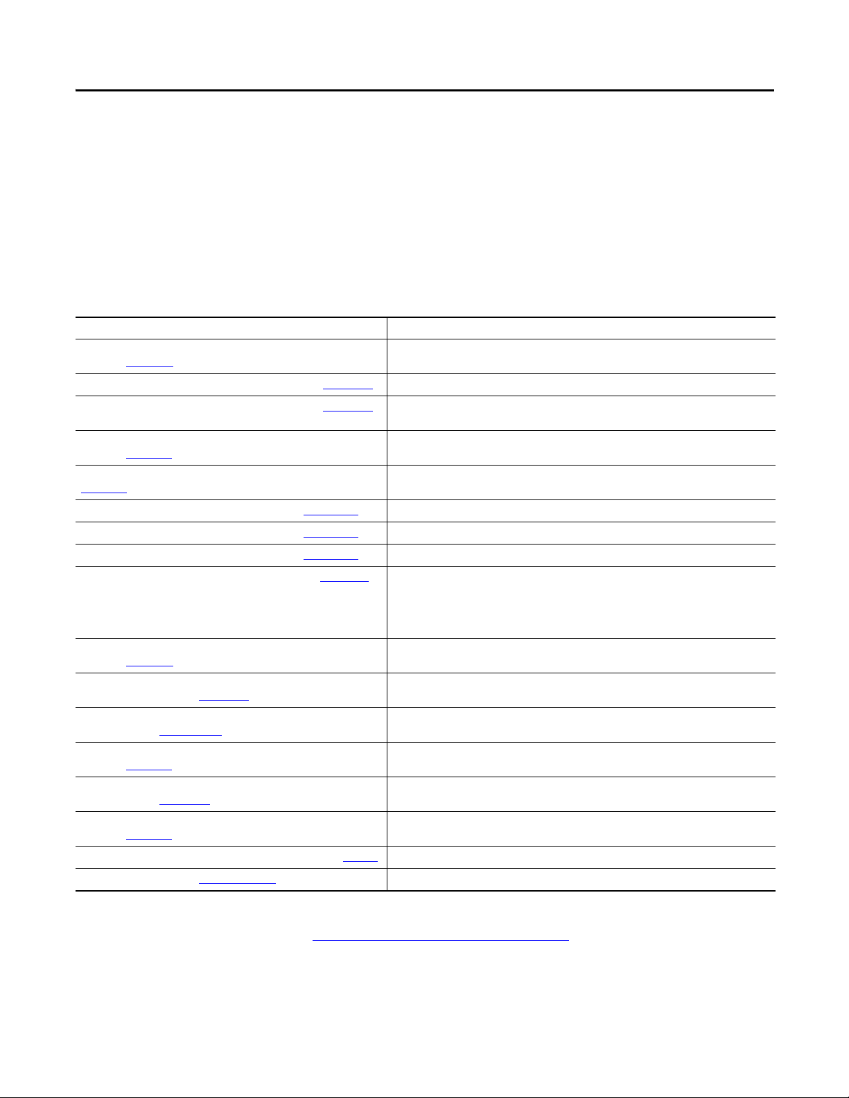
Additional Resources
These resources contain information about related products from Rockwell
Automation.
Resource Description
CompactLogix Controllers Specifications Technical Data,
publication 1769-TD005
1769-SDN DeviceNet Scanner Module User Manual, publication 1769-UM009
Compact High-speed Counter Module User Manual, publication 1769-UM006
Compact I/O DeviceNet Scanner Module Installation Instructions,
publication 1769-IN060
Compact I/O Expansion Power Supplies Installation Instructions, publication
1769-IN028
CompactLogix 5370 L1 Controllers Quick Start, publication IASIMP-QS024
CompactLogix 5370 L2 Controllers Quick Start, publication IASIMP-QS025 Describes basic tasks to design, install and start a CompactLogix 5370 L2 control system.
CompactLogix 5370 L3 Controllers Quick Start, publication IASIMP-QS023 Describes basic tasks to design, install and start a CompactLogix 5370 L3 control system.
Ethernet Design Considerations Reference Manual, publication ENET-RM002
EtherNet/IP Embedded Switch Technology Application Guide,
publication ENET-AP005
Execution Time and Memory Use for Logix5000 Controller Instructions
Reference Manual, publication 1756-RM087
Integrated Motion on the EtherNet/IP Network Configuration and Startup User
Manual, publication MOTION-UM003
POINT I/O 24V dc Expansion Power Supply Installation Instruc tions,
publication 1734-IN058
POINT I/O Digital and Analog Modules and POINTBlock I/O Modules User
Manual, publication 1734-UM001
POINT I/O Field Potential Distributor Modules Installation Instructions,
publication 1734-IN059
Industrial Automation Wiring and Grounding Guidelines, publication 1770-4.1
Product Certifications website, http://w ww.ab.com Provides declarations of conformity, certificates, and other certification details.
Provides CompactLogix controller specifications for all CompactLogix controllers.
Describes how to use the 1769-SDN to back up your CompactLogix 5370 L2 or L3 controller.
Describes high-speed counter operation for standalone 1769-HSC when used with L2 and L3
Compact controllers as well as embedded high-speed counters in L2 embedded controllers.
Describes how to install the Compact I/O™ modules.
Describes how to wire the 1769 Compact I/O power supply.
Describes basic tasks to design, install and start a CompactLogix 5370 L1 control system.
Describes the following concepts that you must consider when designing a control system that
includes an EtherNet/IP network:
• EtherNet/IP overview
• Ethernet infrastructure
• EtherNet/IP protocol
Describes how to use a DLR network topology.
Assists in estimating the memory use and execution time of programmed logic and in selecting
among different programming options.
Describes how to configure an Integrated Motion over
EtherNet/IP motion application and to star t up that motion solution in a Logix5000 control system.
Describes the 1734-EP24DC expansion power supply.
Describes how to return a 1734 POINT I/O module to Autobaud.
Describes the 1734-FPD POINT I/O Field Power Distributor module.
Provides general guidelines for installing a Rockwell Automation industrial system.
You can view or download publications at
http://www.rockwellautomation.com/literature/. To order paper copies of technical
documentation, contact your local Allen-Bradley distributor or
Rockwell Automation sales representative.
Rockwell Automation Publication 1769-UM021G-EN-P - October 2015 11

Chapter 1
Install the CompactLogix 5370 L1 Controller
Top ic Pag e
Before You Begin 16
Install the Secure Digital Card 19
Install the System 21
Connec t to the Controller via a USB Cab le 31
Connect the Controller to an EtherNet/IP Network 32
ATTENTION: Environment and Enclosure
This equipment is intended for use in a Pollution Degree 2 industrial environment, in overvoltage Category II applications (as defined
in IEC 60664-1), at altitudes up to 2000 m (6562 ft) without derating.
This equipment is considered Group 1, Class A industrial equipment according to IEC/CISPR 11. Without appropriate precautions,
there may be difficulties with electromagnetic compatibility in residential and other environments due to conducted and radiated
disturbances.
This equipment is supplied as open-type equipment. It must be mounted within an enclosure that is suitably designed for those
specific environmental conditions that will be present and appropriately designed to prevent personal injury resulting from
accessibility to live parts. The enclosure must have suitable flame-retardant properties to prevent or minimize the spread of flame,
complying with a flame spread rating of 5VA, V2, V1, V0 (or equivalent) if nonmetallic. The interior of the enclosure must be
accessible only by the use of a tool. Subsequent sections of this publication may contain additional information regarding specific
enclosure type ratings that are required to comply with certain product safety certifications.
In addition to this publication, see the following:
• Industrial Automation Wiring and Grounding Guidelines, publication 1770-4.1
• NEMA 250 and IEC 60529, as applicable, for explanations of the degrees of protection provided by enclosures
, for additional installation requirements
Rockwell Automation Publication 1769-UM021G-EN-P - October 2015 13
Chapter 1 Install the CompactLogix 5370 L1 Controller
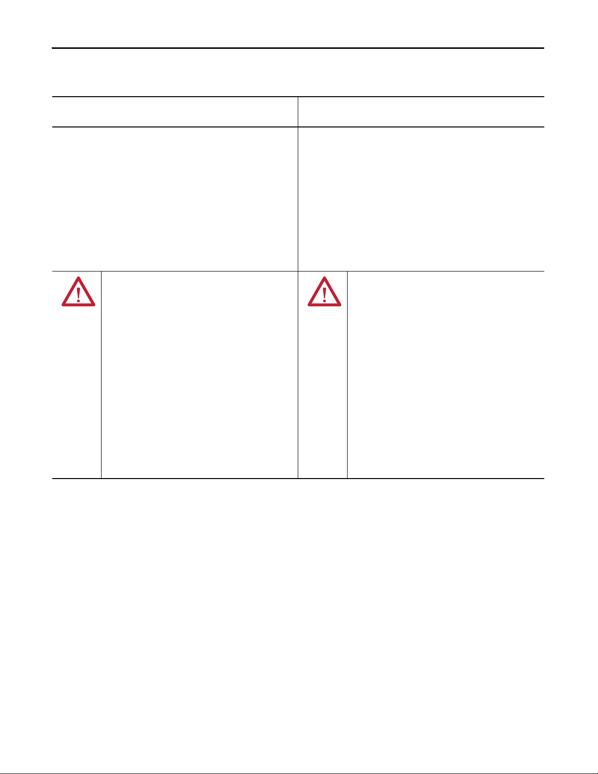
North American Hazardous Location Approval
The following information applies when operating this equipment in
hazardous locations.
Produc ts marked "CL I, DIV 2, GP A, B, C, D" are suitable for use in Class
I Division 2 Groups A, B, C, D, Hazardous Locations and nonhazardous
locations only. Each product is supplied with markings on the rating
nameplate indicating the hazardous location temperature code.
When combining products within a system, the most adverse
temperature code (lowest "T" number) may be used to help
determine the overall temperature code of the system. Combinations
of equipment in your system are subject to investigation by the local
Authority Having Jurisdiction at the time of installation.
WARNING: EXPLOSION HAZARD -
• Do not disconnect equipment unless power has
been removed or the area is known to be
nonhazardous.
• Do not disconnect connections to this equipment
unless power has been removed or the area is
known to be nonhazardous. Secure any external
connections that mate to this equipment by using
screws, sliding latches, threaded connectors, or
other means provided with this product.
• Substitution of components may impair suitability
for Class I, Division 2.
• If this product contains batteries, they must only
be changed in an area known to be nonhazardous.
Informations sur l’utilisation de cet équipement en environnements
dangereux.
Les produits marqués "CL I, DIV 2, GP A, B, C, D" ne conviennent qu'à
une utilisation en environnements de Classe I Division 2 Groupes A, B,
C, D dangereux et non dangereux. Chaque produit est livré avec des
marquages sur sa plaque d'identification qui indiquent le code de
température pour les environnements dangereux. Lorsque plusieurs
produits sont combinés dans un système, le code de température le
plus défavorable (code de température le plus faible) peut être utilisé
pour déterminer le code de température global du système. Les
combinaisons d'équipements dans le système sont sujettes à
inspection par les autorités locales qualifiées au moment de
l'installation.
AVERTISSEMENT: RISQUE D’EXPLOSION –
• Couper le courant ou s'assurer que
l'environnement est classé non dangereux avant
de débrancher l'équipement.
• Couper le courant ou s'assurer que
l'environnement est classé non dangereux avant
de débrancher les connecteurs. Fixer tous les
connecteurs externes reliés à cet équipement à
l'aide de vis, loquets coulissants, connecteurs
filetés ou autres moyens fournis avec ce produit.
• La substitution de composants peut rendre cet
équipement inadapté à une utilisation en
environnement de Classe I, Division 2.
• S'assurer que l'environnement est classé non
dangereux avant de changer les piles.
14 Rockwell Automation Publication 1769-UM021G-EN-P - October 2015

Install the CompactLogix 5370 L1 Controller Chapter 1
European Hazardous Location Approval
The following applies when the product bears the Ex Marking.
This equipment is intended for use in potentially explosive atmospheres as defined by European Union Directive 94/9/EC and has been found to
comply with the Essential Health and Safety Requirements relating to the design and construction of Category 3 equipment intended for use in
Zone 2 potentially explosive atmospheres, given in Annex II to this Directive.
Compliance with the Essential Health and Safety Requirements has been assured by compliance with EN 60079-15 and EN 60079-0.
ATTENTION: This equipment is not resistant to sunlight or other sources of UV radiation.
WARNING:
• This equipment must be installed in an enclosure providing at least IP54 protection when applied in Zone 2 environments.
• This equipment shall be used within its specified ratings defined by Rockwell Automation.
• Provision shall be made to prevent the rated voltage from being exceeded by transient disturbances of more than 40% when
applied in Zone 2 environments.
• Secure any external connections that mate to this equipment by using screws, sliding latches, threaded connectors, or other
means provided with this product.
• Do not disconnect equipment unless power has been removed or the area is known to be nonhazardous.
• Enclosure must be marked with the following: "Warning - Do not open when energized." After installation of equipment into
the enclosure, access to termination compartments shall be dimensioned so that conductors can be readily connected.
ATTENTION: Prevent Electrostatic Discharge
This equipment is sensitive to electrostatic discharge, which can cause internal damage and affect normal operation. Follow these
guidelines when you handle this equipment:
• Touch a grounded object to discharge potential static.
• Wear an approved grounding wriststrap.
• Do not touch connectors or pins on component boards.
• Do not touch circuit components inside the equipment.
• Use a static-safe workstation, if available.
• Store the equipment in appropriate static-safe packaging when not in use.
Rockwell Automation Publication 1769-UM021G-EN-P - October 2015 15
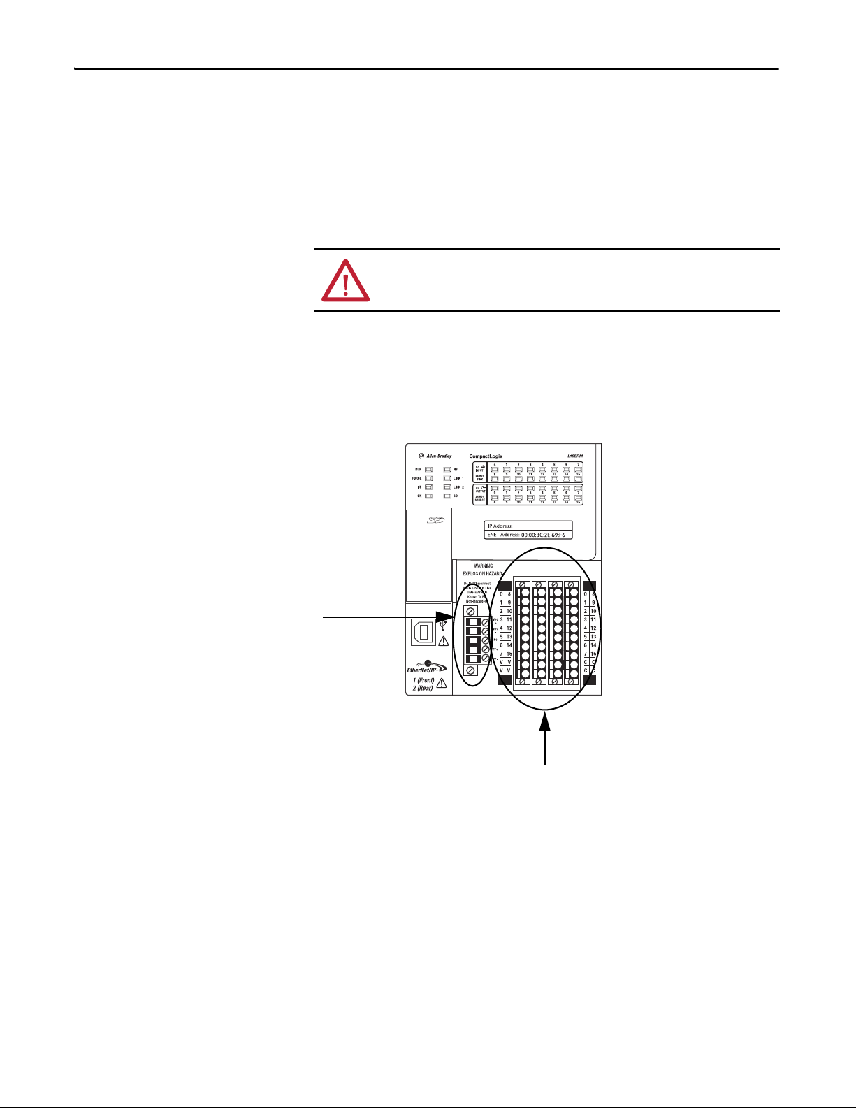
Chapter 1 Install the CompactLogix 5370 L1 Controller
Removable Connector for
Embedded Power Supply
Embedded I/O Module
Before You Begin
The CompactLogix™ 5370 L1, series B, controller redesign occurred to provide
an option to use one external power supply for system power and field side power.
There are differences between the CompactLogix 5370 L1, series A and B,
controllers, which are detailed throughout the sections of this manual.
Consider the following before installing a CompactLogix 5370 L1 controller:
ATT EN TI ON : If this equipment is used in a manner not specified by the
manufacturer, the protection provided by the equipment can be impaired.
• The control system includes the controller, an embedded power supply,
and embedded I/O points.
• The embedded power supply for the series A L16ER, L18ER or L18ERM
controller is a 24V DC nominal, non-isolated power supply with an input
range of 10…28.8V DC. You wire the embedded power supply via a
removable connector.
• The embedded power supply for the series B L16ER, L18ER, L18ERM
and series A L19ER controller is a 24V DC nominal, isolated
power supply with an input range of 10…28.8V DC. You wire the
embedded power supply via a removable connector.
16 Rockwell Automation Publication 1769-UM021G-EN-P - October 2015

Install the CompactLogix 5370 L1 Controller Chapter 1
IMPORTANT
IMPORTANT
You must use a dedicated external Class 2/SELV-approved power
supply to provide power to the system, according to needs of the
application, and within the operating voltage range of the controller
for only series A L16ER, L18ER, and L18ERM controllers.
The external power supply that provides power to the embedded
power supply of the controller cannot be used to provide power to any
other components or devices in the application for only series A L16ER,
L18ER, and L18ERM controllers.
• A second, fused external power supply must be used to provide power to
other components for only series A L16ER, L18ER, and L18ERM
controllers (see Appendix
C).
• Power for other components can be provided from the external power
supply that is used to provide power to the system for only series B L16ER,
L18ER, L18ERM Controllers, and series A L19ER Controllers.
• The controller has 16 embedded digital input points and 16 embedded
digital output points. You wire the input and output points via a removable
connector.
• The controller supports the use of a limited number of
1734 POINT I/O
modules on the POINTBus backplane as local
expansion modules.
You must use the latest series and firmware revision for all 1734
POINT I/O™ modules in the local expansion slots to make sure that your
application operates as expected. Use of an older firmware revision
renders the entire 1734 bus inoperable.
The following table lists local expansion module support by controller
catalog number.
Table 1 - Local Expansion Module Support for CompactLogix 5370 L1 Controllers
Cat. No. 1734 POINT I/O Modules Supported, max
1769-L16ER-BB1B 6
1769-L18ER-BB1B 8
1769-L18ERM-BB1B
1769-L19ER-BB1B
See Chapter 7
for further information about the I/O modules.
Rockwell Automation Publication 1769-UM021G-EN-P - October 2015 17

Chapter 1 Install the CompactLogix 5370 L1 Controller
IMPORTANT
ATT EN TI ON : Do not discard the end cap. Use this end cap to cover the
exposed interconnections on the last mounting base on the DIN rail.
Failure to do so could result in equipment damage or injury from
electric shock.
For more information on how to terminate the end of your system, see
page 25
.
1734 POINT I/O modules support removal and insertion under power.
CompactLogix 5370 L1 Controller Parts
These parts are included in the box when you order your controller:
• Controller - Specific catalog number varies by order
• 1784-SD1 Secure Digital (SD) card with 1 GB of memory storage
Installation Summary
A 1784-SD2 SD card with 2 GB of memory storage, or more 1784-SD1
SD cards, are also available if you need extra memory.
The life expectancy of nonvolatile media is dependent on the number
of write cycles that are performed. Nonvolatile media use a wear
leveling technique or technology for prolonging the service life, but
avoid frequent writes.
Avoid frequent writes when logging data. We recommend that you log
data to a buffer in the memory of your controller and limit the number
of times data is written to removable media.
• An end cap protective cover that slides onto the right side of the
CompactLogix 5370 L1 control system.
To install a CompactLogix 5370 L1 controller, follow these steps.
1. Install the Secure Digital Card
2. Install the System
3. Connect to the Controller via a USB Cable
.
.
.
4. Connect the Controller to an EtherNet/IP Network
18 Rockwell Automation Publication 1769-UM021G-EN-P - October 2015
.
Install the CompactLogix 5370 L1 Controller Chapter 1
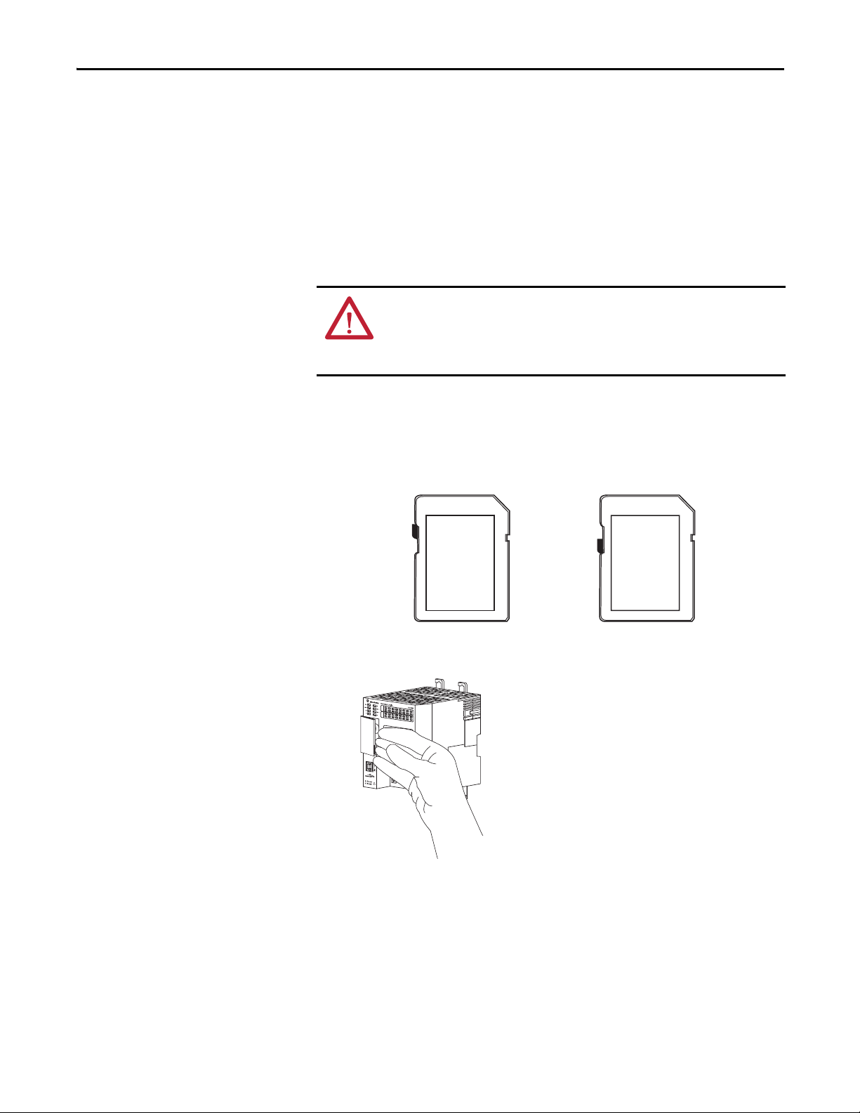
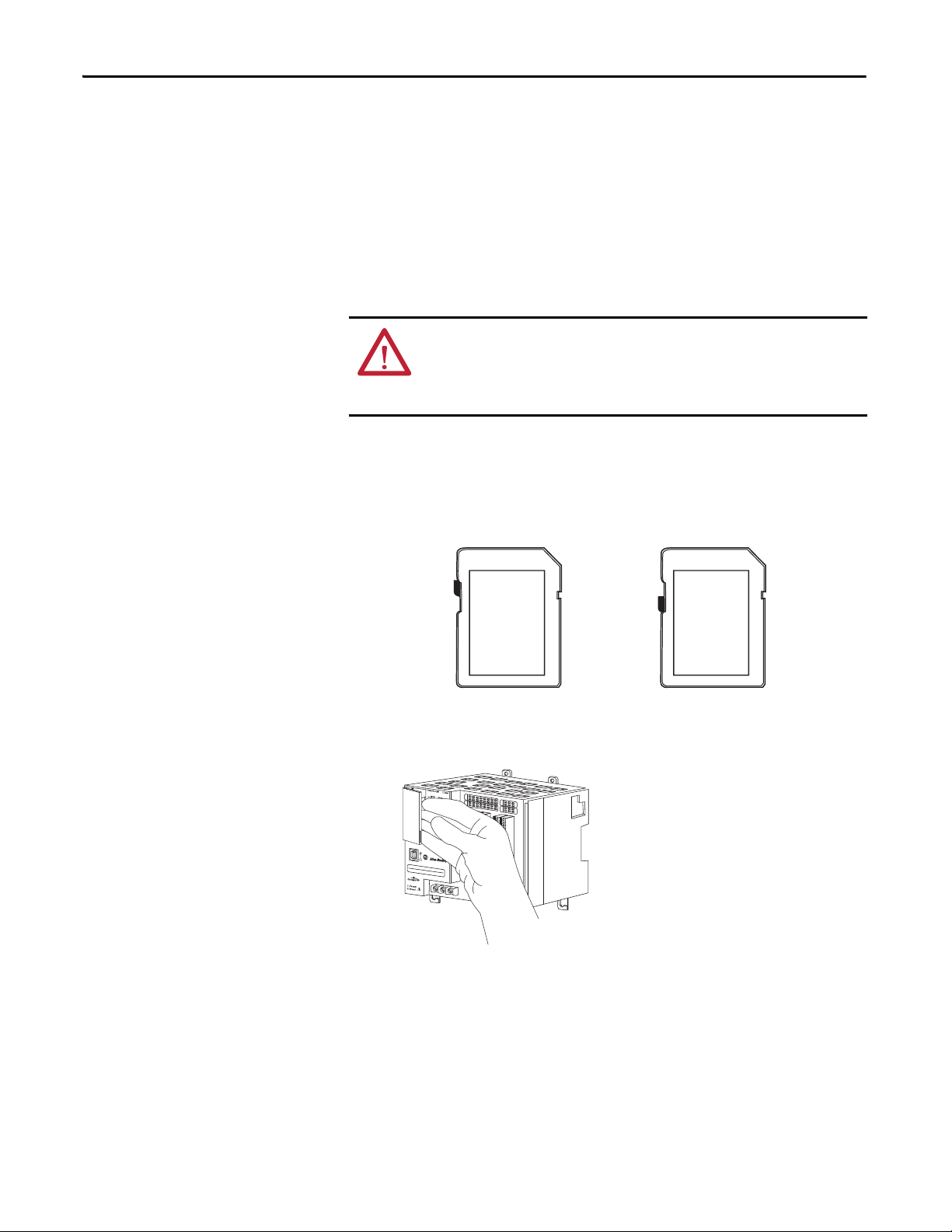
Unlocked Locked
Install the Secure
Digital Card
The CompactLogix 5370 L1 controller is shipped from the factory with the
1784-SD1 SD card installed.
Complete these steps to reinstall an SD card that has been removed from the
controller back into the controller or to install a new SD card into the controller.
We recommend that you leave the SD card in the controller, even when it is not
used. If the controller experiences a major non-recoverable fault, extended fault
information is saved to the card.
WARNING: When you insert or remove the SD card while power is on, an
electrical arc can occur. This could cause an explosion in hazardous location
installations.
Be sure that power is removed or the area is nonhazardous before proceeding.
1. Verify that the SD card is locked or unlocked according to your preference.
Consider the following when deciding to lock the card before installation:
– If the card is unlocked, the controller can write data to it or read data
from it.
2. Open the door for the SD card.
Rockwell Automation Publication 1769-UM021G-EN-P - October 2015 19
Chapter 1 Install the CompactLogix 5370 L1 Controller
3. Insert the SD card into the SD card slot.
You can install the SD card in only one orientation. The beveled corner is
at the top.
If you feel resistance when inserting the SD card, pull it out and change the
orientation.
4. Gently press the card until it clicks into place.
5. Close the SD card door.
We recommend that you keep the SD card door closed during normal
system operation. For more information on using the SD card, see Use a
Secure Digital Card on page 297.
20 Rockwell Automation Publication 1769-UM021G-EN-P - October 2015
Install the CompactLogix 5370 L1 Controller Chapter 1
Install the System
Complete the following steps to install the CompactLogix 5370 L1
control system.
• Mount the System
• Ground the System
• Install the Controller
• Connect Power to the Controller (Series B) L16 ER, L18ER, L18ERM
series B controllers, and series A L19ER
Mount the System
You mount a CompactLogix 5370 L1 control system on a DIN rail. Before you
complete the steps that are required to install the system, install a DIN rail.
WARNING: When used in a Class I, Division 2, hazardous location, this
equipment must be mounted in a suitable enclosure with proper wiring
method that complies with the governing electrical codes.
Before you mount a CompactLogix 5370 L1 control system, consider
the following requirements:
• Available DIN Rails
• Minimum Spacing
• System Dimensions
Available DIN Rails
ATTENTION: This product is grounded through the DIN rail to chassis ground.
Use zinc-plated yellow-chromate steel DIN rail to assure proper grounding.
The use of other DIN rail materials (for example, aluminum or plastic) that
can corrode, oxidize, or are poor conductors, can result in improper or
intermittent grounding. Secure DIN rail to mounting surface approximately
every 200 mm (7.8 in.) and use end-anchors appropriately.
You can mount the CompactLogix 5370 L1 controller on the following
DIN rails:
• EN 50 022 - 35 x 7.5 mm (1.38 x 0.30 in.)
• EN 50 022 - 35 x 15 mm (1.38 x 0.59 in.)
Rockwell Automation Publication 1769-UM021G-EN-P - October 2015 21
Chapter 1 Install the CompactLogix 5370 L1 Controller
IMPORTANT
Bottom
Top
CompactLogix 5370 L1
Controller with
Embedded Power
Supply and I/O Module
End Cap
50 mm
(2 in.)
50 mm
(2 in.)
50 mm
(2 in.)
50 mm
(2 in.)
Side Side
1734 POINT I/O Module
1734 POINT I/O Module
1734 POINT I/O Module
You must install bumpers on the back of your CompactLogix 5370 L1
controller before mounting it on the EN 50022 - 35 x 15 mm
(1.38 x 0.59 in.) DIN rail.
Bumper Selection:
• For more information on Bumper Selection, see Rockwell
Automation® Knowledgebase article #591565. You can access the
article at: (Login required)
https://rockwellautomation.custhelp.com/
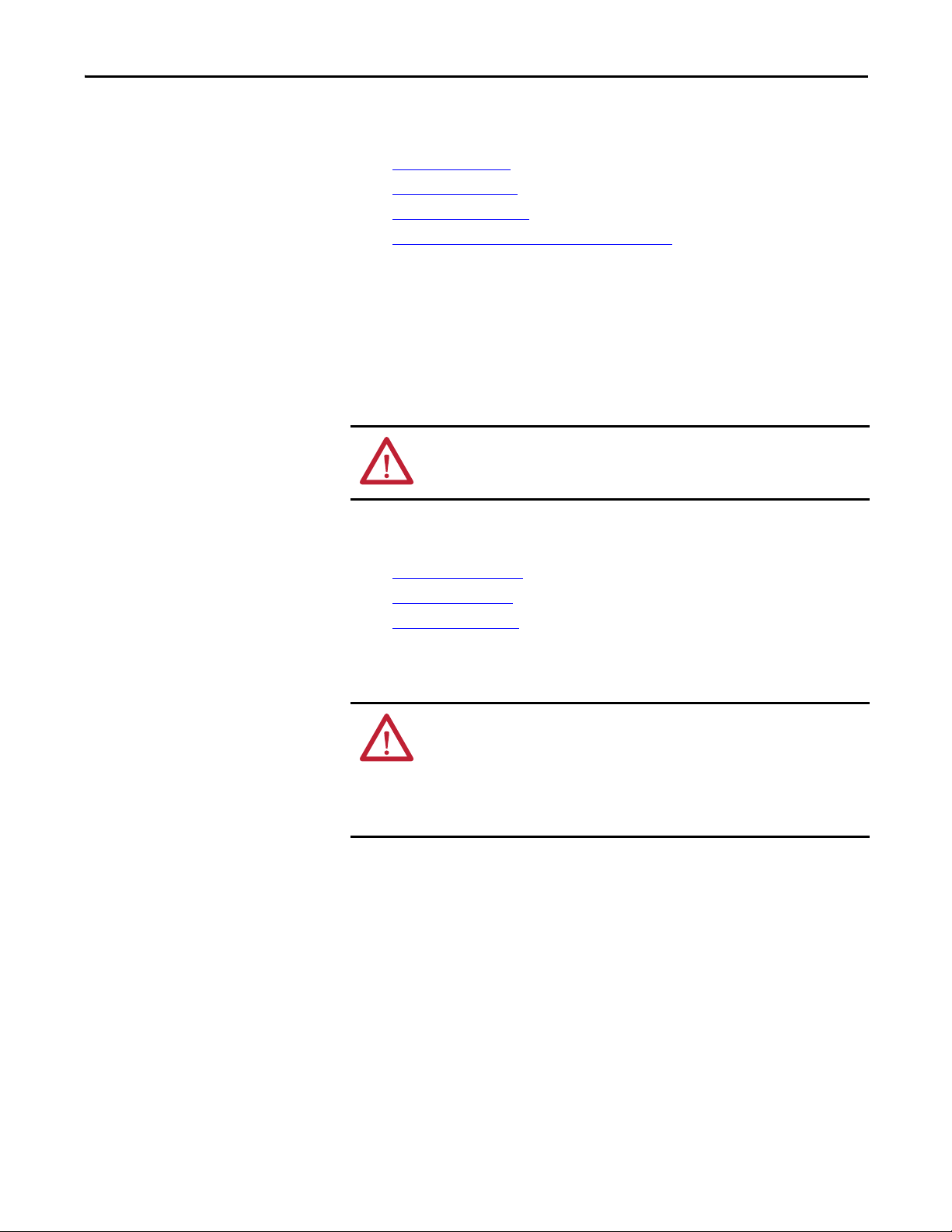
Minimum Spacing
Maintain spacing from enclosure walls, wireways, and adjacent equipment. Allow
50 mm (2 in.) of space on all sides, as shown. This spacing provides ventilation
and electrical isolation.
22 Rockwell Automation Publication 1769-UM021G-EN-P - October 2015
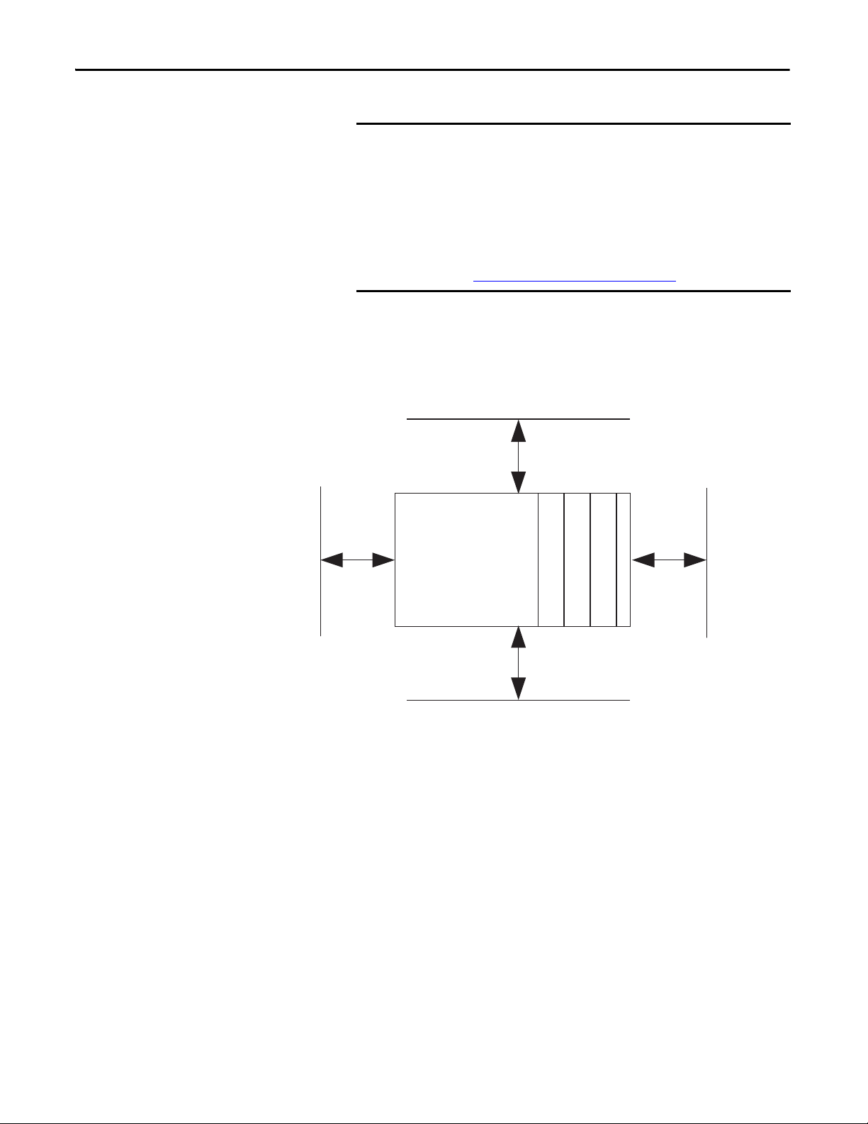
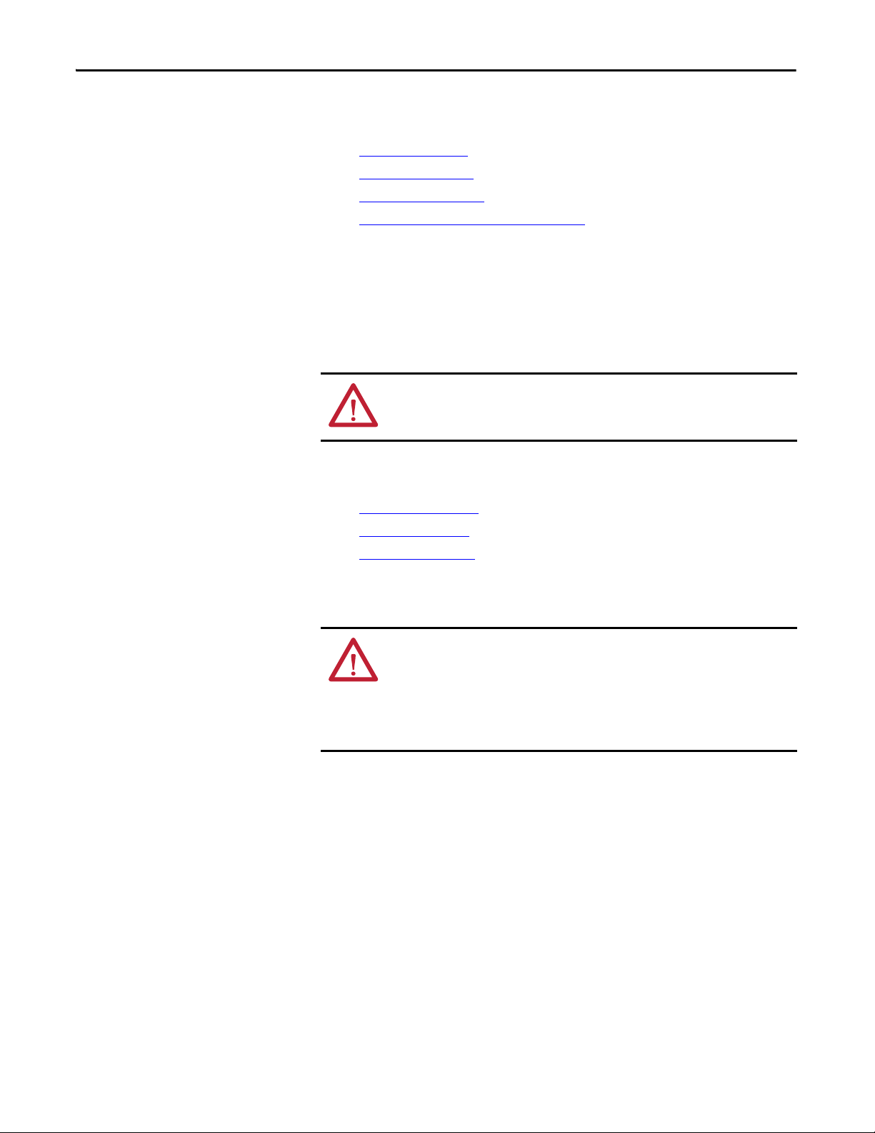
System Dimensions
144.00 mm
(5.67 in.)
130.00 mm
(5.11 in.)
100.00 mm
(3.94 in.)
105 mm
(4.13 in.)
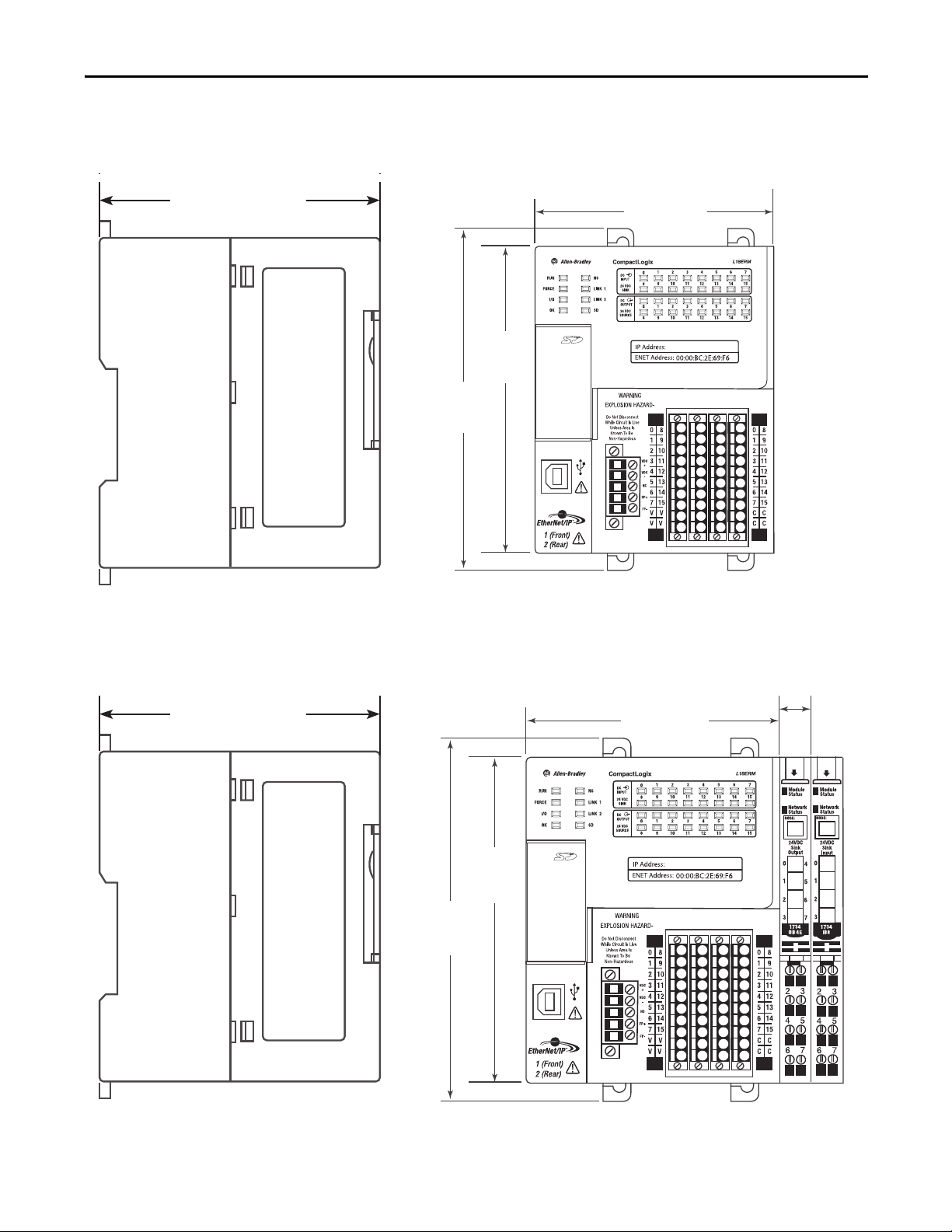
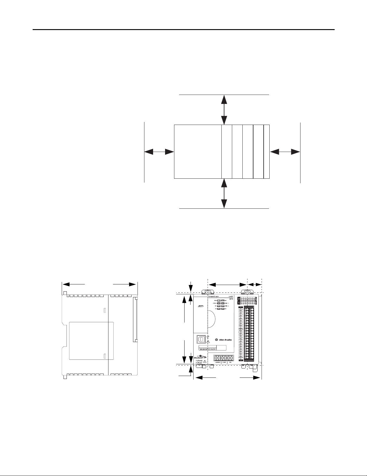
144.00 mm
(5.67 in.)
130.00 mm
(5.11 in.)
100.00 mm
(3.94 in.)
12.00 mm
(0.47 in.)
105 mm
(4.13 in.)
This graphic shows the system dimensions.
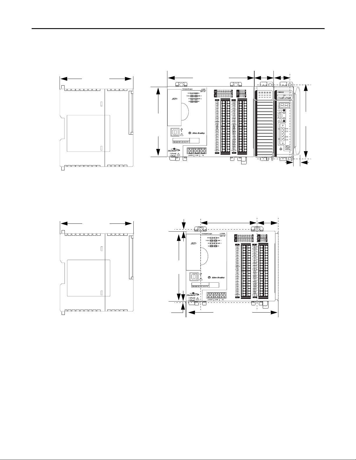
Install the CompactLogix 5370 L1 Controller Chapter 1
This graphic shows the system dimensions with Expansion I/O modules
installed.
Rockwell Automation Publication 1769-UM021G-EN-P - October 2015 23
Chapter 1 Install the CompactLogix 5370 L1 Controller
Ground the System
ATTENTION: This product is intended to be mounted to a well-grounded
mounting surface such as a metal panel. Additional grounding connections
from the power supply's mounting tabs or DIN rail (if used) are not required
unless the mounting surface cannot be grounded.
See Industrial Automation Wiring and Grounding Guidelines, Rockwell
Automation publication 1770-4.1
, for additional information.
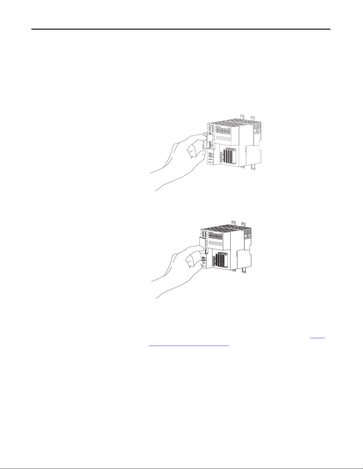
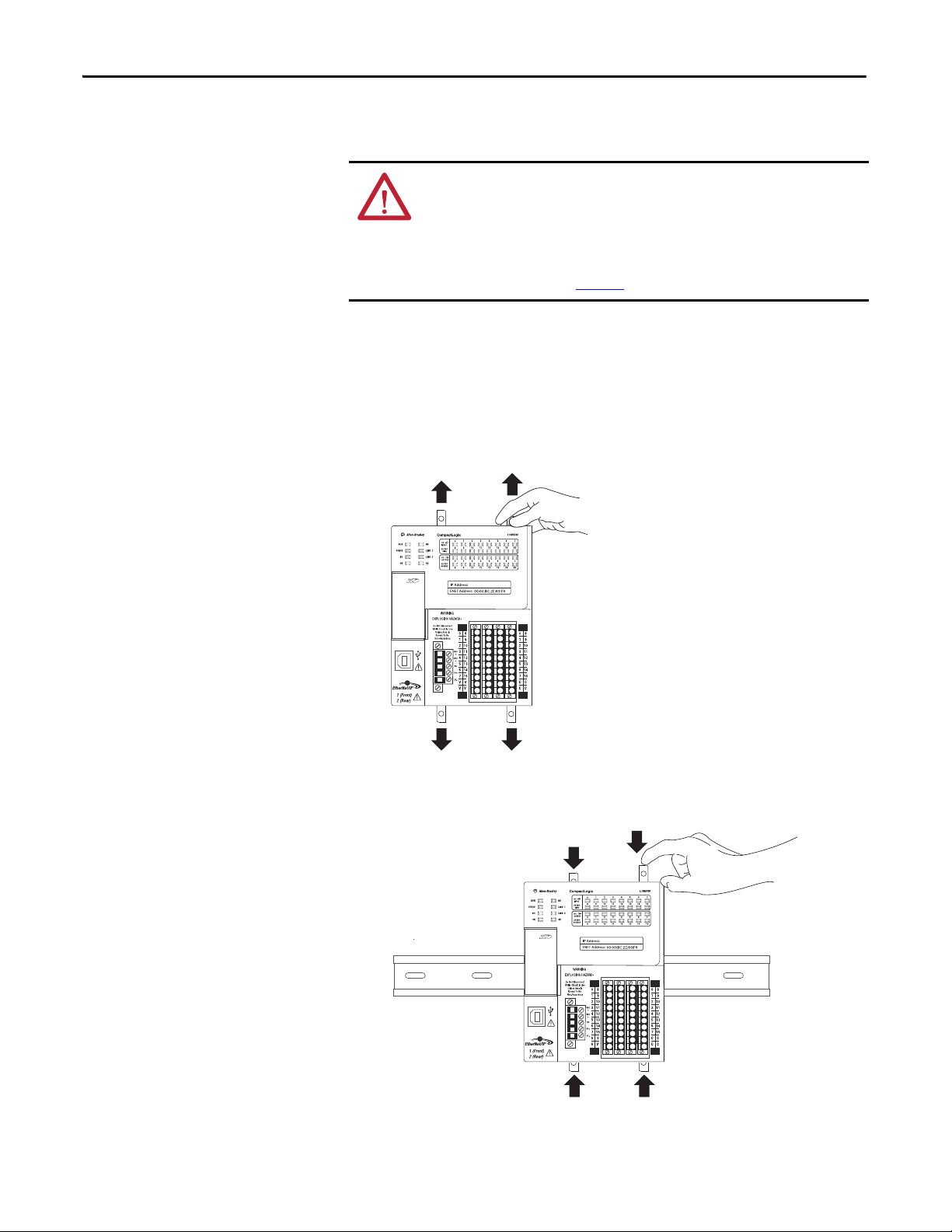
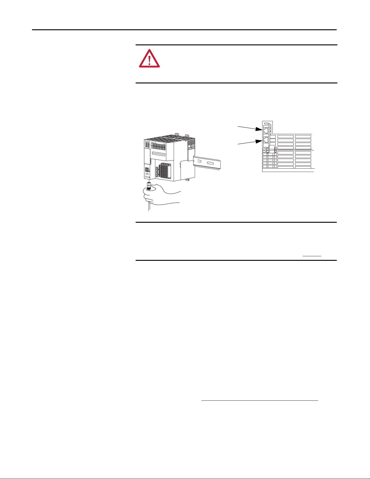
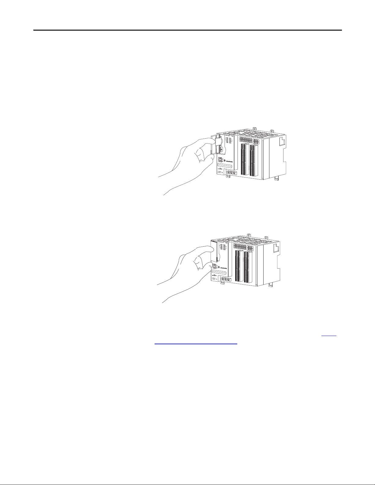
Install the Controller
Complete these steps to install the controller.
1. Pull out the locking tabs.
2. Slide the controller into position on the DIN rail and push the locking
tabs in.
24 Rockwell Automation Publication 1769-UM021G-EN-P - October 2015
Install the CompactLogix 5370 L1 Controller Chapter 1
Thermocouple
Input
Module
Status
Network
Status
1734
IT2I
NODE:
0
1
Insert the module straight
down into the mounting base.
Hook the RTB end into
the mounting base
end and rotate until it
locks into place.
44012
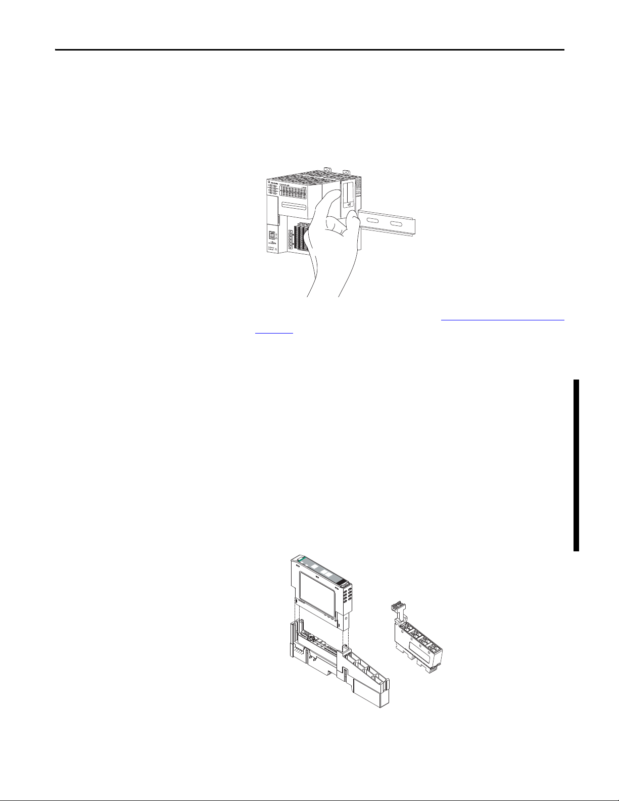
3. If you are not using local expansion modules, use the tongue-and-groove
slots on the right side of the controller to slide a protective covering onto
the controller. The protective cover ships with the controller.
The covering covers the exposed interconnections on the right side of the
controller. Failure to use a protective covering can result in equipment
damage or injury from electric shock.
If you are using local expansion modules, see Local Expansion Modules
on
page 158 for more information on how to install them in a
CompactLogix 5370 L1 control system.
Install the Removable Terminal Block
A removable terminal block (RTB) is supplied with your wiring base assembly. To
remove, pull up on the RTB handle. This allows the mounting base to be
removed and replaced as necessary without removing any of the wirings. To
reinsert the removable terminal block, proceed as follows:
1. Insert the end opposite the handle into the base unit. This end has a curved
section that engages with the wiring base.
2. Rotate the RTB into the wiring base until it locks itself in place.
3. If an I/O module is installed, snap the RTB handle into place on the
module.
Rockwell Automation Publication 1769-UM021G-EN-P - October 2015 25
Chapter 1 Install the CompactLogix 5370 L1 Controller
IMPORTANT
WARNING: When you connect or disconnect the RTB with field-side power
applied, an electrical arc can occur. This can cause an explosion in hazardous
location installations.
Be sure that power is removed or the area is nonhazardous before proceeding.
Connect Power to the Controller (Series B)
For information to connect power to a series A L1 controller, see Appendix C.
This section describes how to power the controller via the VDC+ and VDCterminals.
Connections to the VDC+ and VDC- terminals do not provide power to input or
output devices that are connected to the embedded I/O modules of the
controller or local expansion modules. Power must be connected to the FP+
and FP- terminals to provide power to input or output devices that are
connected to the embedded I/O modules of the controller or local expansion
modules.
The external power supply can be used to power both the VDC+/- and FP+/terminals on the series B L1 controller, see page 144
For more information on how to provide power to input or output devices that
are connected to the embedded I/O modules of the controller and local
expansion modules, see page 144
.
.
WARNING: Do not connect directly to line voltage. Line voltage must be
supplied by a suitable, approved isolating transformer or power supply having
short circuit capacity not exceeding 100VA maximum or equivalent. The
controller power requirement is 30VA.
26 Rockwell Automation Publication 1769-UM021G-EN-P - October 2015
Install the CompactLogix 5370 L1 Controller Chapter 1
IMPORTANT
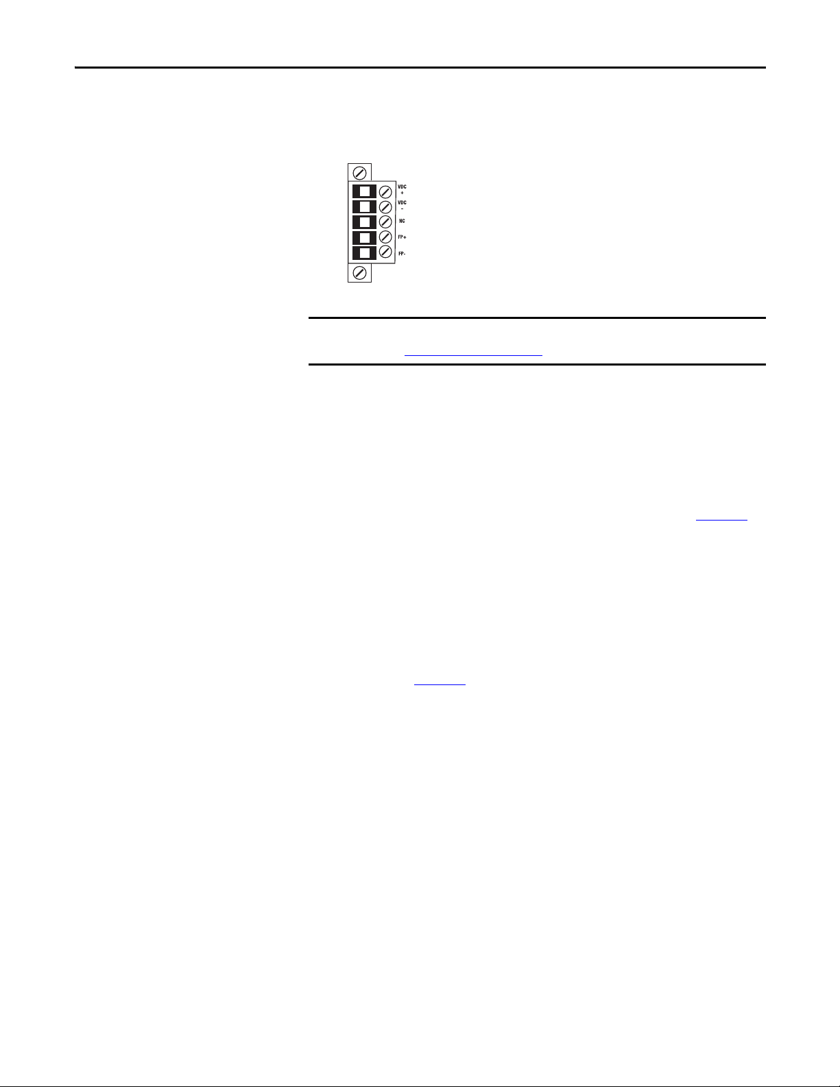
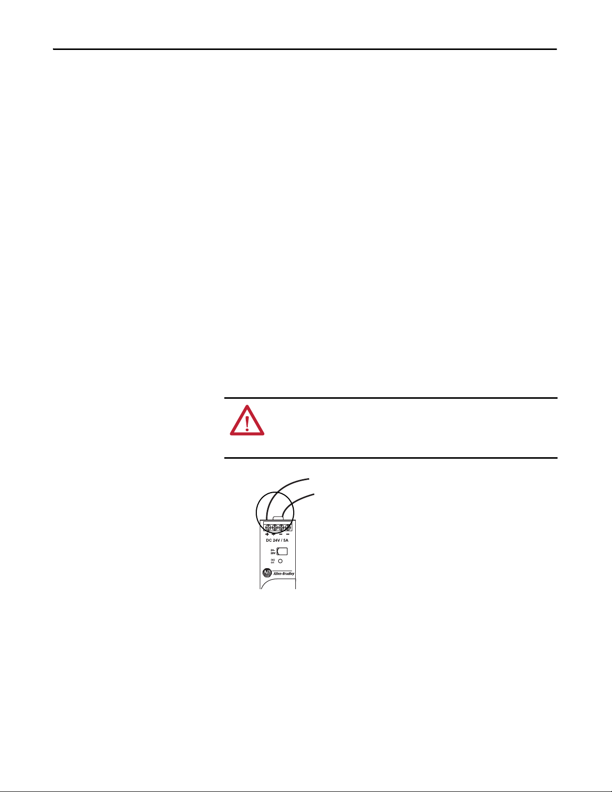
Power is connected to the controller via a removable connector that is connected
to the front of the controller. The following graphic shows the connector.
The controller is grounded once it is installed on a DIN rail as described in
Mount the System
on page 21.
Consider these points before completing the steps in this section:
• This section describes how to connect an external 24V DC power source
to the CompactLogix 5370 L1 controller.
For information on how to provide field power to input and output
devices that are connected to the embedded I/O modules of the controller
and local expansion modules via the removable connector, see page 144
• Use a power source that most effectively meets your application needs.
That is, calculate The power requirements for your application before
choosing a power source to avoid using a power source that far exceeds
your application requirements.
• This section assumes that any DIN rail you use has been grounded
following Industrial Automation Wiring and Grounding Guidelines,
publication 1770-4.1
.
• The embedded power supply of the CompactLogix 5370 L1 controller
provides power to the controller and POINTBus backplane.
.
Rockwell Automation Publication 1769-UM021G-EN-P - October 2015 27
Chapter 1 Install the CompactLogix 5370 L1 Controller
• Not all Class 2/SELV-listed power supplies are certified for use in all
applications, for example, use in nonhazardous and hazardous
environments.
Before installing an external power supply, consult all specification and
certification information to verify that you are using an acceptable external
power supply.
• Only for example purposes, this section describes how to use a 1606XLE120E, NEC Class 2 switched-mode power supply. The exact steps for
other external power supplies can vary from the steps that are described
here.
Complete these steps to connect power to the CompactLogix series B L16ER,
L18ER, L18ERM and series A L19ER controllers.
1. Verify that the external 24V DC power source is not powered.
2. Mount the external 24V DC power source on a DIN rail.
The external 24V DC power source can be installed on the same DIN rail
as the controller or a separate DIN rail.
3. Connect wires to the 24V DC+ and 24V DC- connections on the external
24V DC power source.
WARNING: If you connect or disconnect wiring while the field-side power is on,
an electrical arc can occur. This could cause an explosion in hazardous location
installations. Be sure that power is removed or the area is nonhazardous before
proceeding.
28 Rockwell Automation Publication 1769-UM021G-EN-P - October 2015
Install the CompactLogix 5370 L1 Controller Chapter 1
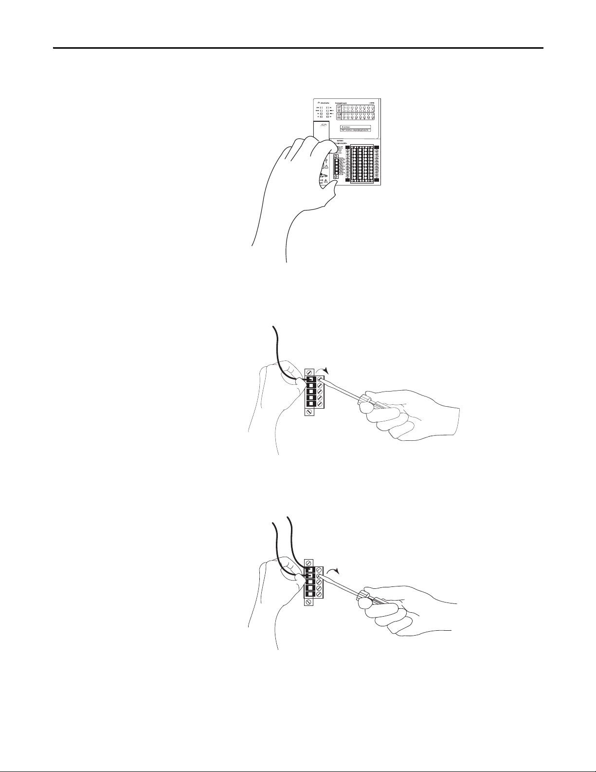
4. Pull the removable connector off the CompactLogix 5370 L1 controller.
5. Connect the wire that is connected to the 24V DC+ terminal on the
external 24V DC power source to the VDC+ terminal, that is, the top
terminal, on the removable connector.
6. Connect the wire that is connected to the 24V DC- terminal on the
external 24V DC power source to the VDC- terminal, that is, the terminal
that is second from the top, on the removable connector.
Rockwell Automation Publication 1769-UM021G-EN-P - October 2015 29
Chapter 1 Install the CompactLogix 5370 L1 Controller
IMPORTANT
If your application requires a power control device, for example, a
switch or relay, between the external 24V DC power source and the
CompactLogix 5370 L1 controller to control when the controller is
powered, you must install the power control device at the VDC+
terminal on the removable connector.
If you install the power control device at the VDC- terminal, the
CompactLogix 5370 L1 controller can have problems powering up or
powering down properly.
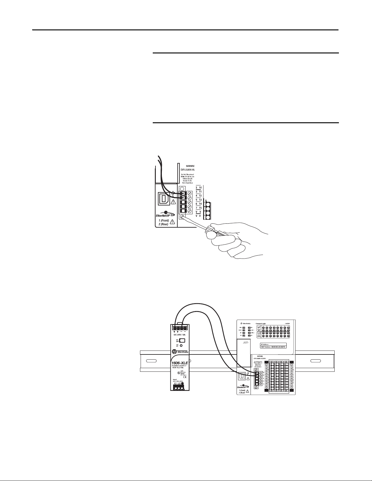
7. Plug the removable connector back into the controller.
8. Secure the removable connector in place.
9. Turn on power to the external 24V DC power source.
The following graphic shows an external 24V DC power source that is connected
to a CompactLogix 5370 L1 controller.
30 Rockwell Automation Publication 1769-UM021G-EN-P - October 2015
Install the CompactLogix 5370 L1 Controller Chapter 1
Connect to the Controller via
a USB Cable
The controller has a USB port that uses a Type B receptacle. The port is USB
2.0-compatible and operates at 12 Mbps.
Use a USB cable to connect your computer to the USB port. With this
connection, you can upgrade firmware and download programs to the controller
directly from your computer.
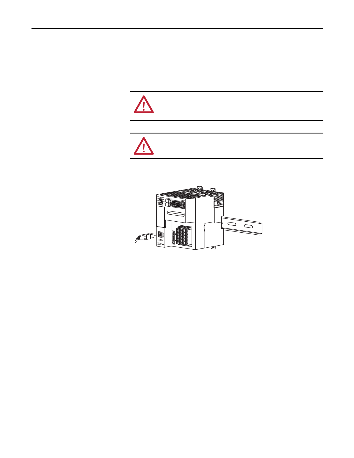
ATTENTION: The USB port is intended only for temporary local
programming purposes and not intended for permanent connection.
The USB cable is not to exceed 3.0 m (9.84 ft) and must not contain hubs.
WARNING: Do not use the USB port in hazardous locations.
Plug the USB cable into the CompactLogix 5370 L1 controller.
Rockwell Automation Publication 1769-UM021G-EN-P - October 2015 31
Chapter 1 Install the CompactLogix 5370 L1 Controller
IMPORTANT
Port 1 - Fron t
Port 2 - Bac k
Bottom of Controller
Connect the Controller to an
EtherNet/IP Network
WARNING: If you connect or disconnect the communication cable with
power applied to this module or any device on the network, an electrical arc
can occur. This could cause an explosion in hazardous location installations.
Be sure that power is removed or the area is nonhazardous before proceeding.
Connect the RJ45 connector of the Ethernet cable to one of the Ethernet ports
on the controller. The ports are on the bottom of the controller.
This example shows how to connect the controller to the network through one
port. Depending on the network topology of your application, you can connect
both ports of the controller to the EtherNet/IP network.
For more information on EtherNet/IP network topologies, see page 127
.
Connecting to Different EtherNet/IP Network Topologies
CompactLogix 5370 L1 controllers have embedded switch technology and two
EtherNet/IP ports that let you use it in various EtherNet/IP network topologies:
• Device-level ring network topology - Both ports on the controller are
connected to the network.
• Linear network topology - Both ports on the controller are connected to
the network.
• Star network topology - One port on the controller is connected to
the network.
There are connection and configuration requirements for each EtherNet/IP
network topology.
For more information, see EtherNet/IP Network Topologies
on page 127.
32 Rockwell Automation Publication 1769-UM021G-EN-P - October 2015
Chapter 2
Install the CompactLogix 5370 L2 Controller
Top ic Pag e
Before You Begin 36
Install the Secure Digital Card 38
Install the System 40
Connec t to the Controller via a USB Cab le 53
Connect the Controller to an EtherNet/IP Network 54
ATTENTION: Environment and Enclosure
This equipment is intended for use in a Pollution Degree 2 industrial environment, in overvoltage Category II applications (as defined
in IEC 60664-1), at altitudes up to 2000 m (6562 ft) without derating.
This equipment is considered Group 1, Class A industrial equipment according to IEC/CISPR 11. Without appropriate precautions,
there may be difficulties with electromagnetic compatibility in residential and other environments due to conducted and radiated
disturbances.
This equipment is supplied as open-type equipment. It must be mounted within an enclosure that is suitably designed for those
specific environmental conditions that will be present and appropriately designed to prevent personal injury resulting from
accessibility to live parts. The enclosure must have suitable flame-retardant properties to prevent or minimize the spread of flame,
complying with a flame spread rating of 5VA, V2, V1, V0 (or equivalent) if nonmetallic. The interior of the enclosure must be
accessible only by the use of a tool. Subsequent sections of this publication may contain additional information regarding specific
enclosure type ratings that are required to comply with certain product safety certifications.
In addition to this publication, see the following:
• Industrial Automation Wiring and Grounding Guidelines, publication 1770-4.1
• NEMA 250 and IEC 60529, as applicable, for explanations of the degrees of protection provided by enclosures
, for additional installation requirements
Rockwell Automation Publication 1769-UM021G-EN-P - October 2015 33

Chapter 2 Install the CompactLogix 5370 L2 Controller
North American Hazardous Location Approval
The following information applies when operating this equipment in
hazardous locations.
Produc ts marked "CL I, DIV 2, GP A, B, C, D" are suitable for use in Class
I Division 2 Groups A, B, C, D, Hazardous Locations and nonhazardous
locations only. Each product is supplied with markings on the rating
nameplate indicating the hazardous location temperature code.
When combining products within a system, the most adverse
temperature code (lowest "T" number) may be used to help
determine the overall temperature code of the system. Combinations
of equipment in your system are subject to investigation by the local
Authority Having Jurisdiction at the time of installation.
WARNING: EXPLOSION HAZARD -
• Do not disconnect equipment unless power has
been removed or the area is known to be
nonhazardous.
• Do not disconnect connections to this equipment
unless power has been removed or the area is
known to be nonhazardous. Secure any external
connections that mate to this equipment by using
screws, sliding latches, threaded connectors, or
other means provided with this product.
• Substitution of components may impair suitability
for Class I, Division 2.
• If this product contains batteries, they must only
be changed in an area known to be nonhazardous.
Informations sur l’utilisation de cet équipement en environnements
dangereux.
Les produits marqués "CL I, DIV 2, GP A, B, C, D" ne conviennent qu'à
une utilisation en environnements de Classe I Division 2 Groupes A, B,
C, D dangereux et non dangereux. Chaque produit est livré avec des
marquages sur sa plaque d'identification qui indiquent le code de
température pour les environnements dangereux. Lorsque plusieurs
produits sont combinés dans un système, le code de température le
plus défavorable (code de température le plus faible) peut être utilisé
pour déterminer le code de température global du système. Les
combinaisons d'équipements dans le système sont sujettes à
inspection par les autorités locales qualifiées au moment de
l'installation.
AVERTISSEMENT: RISQUE D’EXPLOSION –
• Couper le courant ou s'assurer que
l'environnement est classé non dangereux avant
de débrancher l'équipement.
• Couper le courant ou s'assurer que
l'environnement est classé non dangereux avant
de débrancher les connecteurs. Fixer tous les
connecteurs externes reliés à cet équipement à
l'aide de vis, loquets coulissants, connecteurs
filetés ou autres moyens fournis avec ce produit.
• La substitution de composants peut rendre cet
équipement inadapté à une utilisation en
environnement de Classe I, Division 2.
• S'assurer que l'environnement est classé non
dangereux avant de changer les piles.
34 Rockwell Automation Publication 1769-UM021G-EN-P - October 2015
Install the CompactLogix 5370 L2 Controller Chapter 2
European Hazardous Location Approval
The following applies when the product bears the Ex Marking.
This equipment is intended for use in potentially explosive atmospheres as defined by European Union Directive 94/9/EC and has been found to
comply with the Essential Health and Safety Requirements relating to the design and construction of Category 3 equipment intended for use in
Zone 2 potentially explosive atmospheres, given in Annex II to this Directive.
Compliance with the Essential Health and Safety Requirements has been assured by compliance with EN 60079-15 and EN 60079-0.
ATTENTION: This equipment is not resistant to sunlight or other sources of UV radiation.
WARNING:
• This equipment must be installed in an enclosure providing at least IP54 protection when applied in Zone 2 environments.
• This equipment shall be used within its specified ratings defined by Rockwell Automation.
• Provision shall be made to prevent the rated voltage from being exceeded by transient disturbances of more than 40% when
applied in Zone 2 environments.
• Secure any external connections that mate to this equipment by using screws, sliding latches, threaded connectors, or other
means provided with this product.
• Do not disconnect equipment unless power has been removed or the area is known to be nonhazardous.
• Enclosure must be marked with the following: "Warning - Do not open when energized." After installation of equipment into
the enclosure, access to termination compartments shall be dimensioned so that conductors can be readily connected.
ATTENTION: Prevent Electrostatic Discharge
This equipment is sensitive to electrostatic discharge, which can cause internal damage and affect normal operation. Follow these
guidelines when you handle this equipment:
• Touch a grounded object to discharge potential static.
• Wear an approved grounding wriststrap.
• Do not touch connectors or pins on component boards.
• Do not touch circuit components inside the equipment.
• Use a static-safe workstation, if available.
• Store the equipment in appropriate static-safe packaging when not in use.
Rockwell Automation Publication 1769-UM021G-EN-P - October 2015 35

Chapter 2 Install the CompactLogix 5370 L2 Controller
Embedded Power
Supply Terminals
Embedded I/O Modules
1769-L24ER-QBFC1B Control
End Cap
Before You Begin
Consider the following before installing a CompactLogix™ 5370 L2 controller:
• The control system includes a controller, an embedded power supply,
embedded I/O points, and a 1769-ECR right end cap.
• The embedded power supply is a 24V DC input, isolated power supply
The following graphic shows an example CompactLogix 5370 L2
controller.
ATTENTION: You must use an external power supply that is Class 2 or
SELV-listed for series A L1 controllers.
For example, you can use a 1606-XLSDNET4, standard switched-mode
power supply, as shown in this chapter.
• The controllers have embedded I/O points. You wire the input and output
points via a removable connector.
• The controller supports the use of up to four Compact I/O™ modules on
the local 1769 CompactBus backplane as local expansion modules.
For more information on using embedded I/O points and local
expansion modules, see Chapter 8, Use I/O Modules with
CompactLogix 5370 L2 Controllers on page 183.
• You must terminate the end of the CompactBus via a 1769-ECR right end
cap as shown in step 6 on page 47
.
• You cannot remove nor install Compact I/O modules while the controller
is powered.
36 Rockwell Automation Publication 1769-UM021G-EN-P - October 2015

Install the CompactLogix 5370 L2 Controller Chapter 2
IMPORTANT
ATTENTION: CompactLogix 5370 L2 control systems do not support
removal and insertion under power (RIUP). Removing a 1769 Compact
I/O module or end cap generates a controller fault and may also result in
damage to system components.
CompactLogix 5370 L2 Controller Parts
These parts are included in the box when you order your controller:
• Controller - Specific catalog number varies by order
• 1769-ECR Compact I/O end cap/terminator
• 1784-SD1 Secure Digital (SD) card with 1 GB of memory storage
A 1784-SD2 SD card with 2 GB of memory storage, or more1784-SD1
SD cards, are also available if you need extra memory.
Installation Summary
The life expectancy of nonvolatile media is dependent on the number
of write cycles that are performed. Nonvolatile media use a wear
leveling technique or technology for prolonging the service life, but
avoid frequent writes.
Avoid frequent writes when logging data. We recommend that you log
data to a buffer in the memory of your controller and limit the number
of times data is written to removable media.
To install a CompactLogix 5370 L2 controller, follow these steps.
1. Install the Secure Digital Card
2. Install the System
3. Connect to the Controller via a USB Cable
4. Connect the Controller to an EtherNet/IP Network
.
.
.
.
Rockwell Automation Publication 1769-UM021G-EN-P - October 2015 37
Chapter 2 Install the CompactLogix 5370 L2 Controller
Unlocked Locked
Install the Secure
Digital Card
The CompactLogix 5370 L2 controller is shipped from the factory with the
1784-SD1 SD card installed.
Complete these steps to reinstall an SD card that has been removed from the
controller back into the controller or to install a new SD card into the controller.
We recommend that you leave the SD card in the controller, even when it is not
used. If the controller experiences a Major Non-recoverable Fault, extended fault
information is saved to the card.
WARNING: When you insert or remove the SD card while power is on, an
electrical arc can occur. This could cause an explosion in hazardous location
installations.
Be sure that power is removed or the area is nonhazardous before proceeding.
1. Verify that the SD card is locked or unlocked according to your preference.
Consider the following when deciding to lock the card before installation:
– If the card is unlocked, the controller can write data to it or read data
from it.
38 Rockwell Automation Publication 1769-UM021G-EN-P - October 2015
2. Open the door for the SD card.
Install the CompactLogix 5370 L2 Controller Chapter 2
3. Insert the SD card into the SD card slot.
You can install the SD card in one orientation only. The beveled corner is
at the bottom.
If you feel resistance when inserting the SD card, pull it out and change the
orientation.
4. Gently press the card until it clicks into place.
5. Close the SD card door.
We recommend that you keep the SD card door closed during normal
system operation. For more information on using the SD card, see Use a
Secure Digital Card on page 297.
Rockwell Automation Publication 1769-UM021G-EN-P - October 2015 39
Chapter 2 Install the CompactLogix 5370 L2 Controller
Install the System
Complete the following tasks to install the CompactLogix 5370 L2
control system:
• Mount the System
• Ground the System
• Install the Controller
• Connect Power to the Control System
Mount the System
You can mount a CompactLogix 5370 L2 control system on a DIN rail or
apanel.
WARNING: When used in a Class I, Division 2, hazardous location, this
equipment must be mounted in a suitable enclosure with proper wiring
method that complies with the governing electrical codes.
Before you mount a CompactLogix 5370 L2 control system, consider
the following requirements:
• Available DIN Rails
• Minimum Spacing
• System Dimensions
Available DIN Rails
ATTENTION: This product is grounded through the DIN rail to chassis ground.
Use zinc-plated yellow-chromate steel DIN rail to assure proper grounding.
The use of other DIN rail materials (for example, aluminum or plastic) that
can corrode, oxidize, or are poor conductors, can result in improper or
intermittent grounding. Secure DIN rail to mounting surface approximately
every 200 mm (7.8 in.) and use end-anchors appropriately.
You can mount the CompactLogix 5370 L2 controller on the following
DIN rails:
• EN 50 022 - 35 x 7.5 mm (1.38 x 0.30 in.)
• EN 50 022 - 35 x 15 mm (1.38 x 0.59 in.)
40 Rockwell Automation Publication 1769-UM021G-EN-P - October 2015
Install the CompactLogix 5370 L2 Controller Chapter 2
Bottom
Top
CompactLogix 5370 L2
Controller wi th
Embedded Power
Supply and I/O Points
End Cap
50 mm
(2 in.)
50 mm
(2 in.)
50 mm
(2 in.)
50 mm
(2 in.)
Side Side
Compact I/O Module
Compact I/O Module
Compact I/O Module
Compact I/O Module
118.00 mm
(4.65 in.)
105 mm
(4.13 in.)
115.00 mm
(4.53 in.)
27.65 mm
(1.09 in.)
59.70 mm
(2.35 in.)
3.06 mm
(0.12 in.)
2.8 mm
(0.12 in.)
Minimum Spacing
Maintain spacing from enclosure walls, wireways, and adjacent equipment. Allow
50 mm (2 in.) of space on all sides, as shown. This spacing provides ventilation
and electrical isolation.
System Dimensions
This graphic shows the system dimensions for the
1769-L24ER-QB1B controller.
Rockwell Automation Publication 1769-UM021G-EN-P - October 2015 41

Chapter 2 Install the CompactLogix 5370 L2 Controller
118.00 mm
(4.65 in.)
115.00 mm
(4.53 in.)
35.00 mm
(1.38 in.)
105 mm
(4.13 in.)
18.00 mm
(0.71 in.)
25.00 mm
(0.98 in.)
126.6 mm
(4.98 in.)
118.00 mm
(4.65 in.)
105 mm
(4.13 in.)
140.00 mm
(5.51 in.)
27.65 mm
(1.09 in.)
84.70 mm
(3.33 in.)
3.06 mm
(0.12 in.)
2.8 mm
(0.12 in.)
This graphic shows the system dimensions for the 1769-L24ER-QB1B controller
with expansion modules installed.
This graphic shows the system dimensions for the
1769-L24ER-QBFC1B controller.
42 Rockwell Automation Publication 1769-UM021G-EN-P - October 2015
Install the CompactLogix 5370 L2 Controller Chapter 2
118.00 mm
(4.65 in.)
35.00 mm
(1.38 in.)
105 mm
(4.13 in.)
140.00 mm
(5.51 in.)
18.00 mm
(0.71 in.)
25.00 mm
(0.98 in.)
126.6 mm
(4.98 in.)
118.00 mm
(4.65 in.)
105 mm
(4.13 in.)
140.00 mm
(5.51 in.)
84.70 mm
(3.33 in.)
27.65 mm
(1.09 in.)
3.06 mm
(0.12 in.)
2.8 mm
(0.12 in.)
This graphic shows the system dimensions for the 1769-L24ER-QBFC1B
controller with expansion modules installed.
This graphic shows the system dimensions for the
1769-L27ERM-QBFC1B controller.
This graphic shows the system dimensions for the
1769-L27ERM-QBFC1B controller with expansion modules installed.
Rockwell Automation Publication 1769-UM021G-EN-P - October 2015 43

Chapter 2 Install the CompactLogix 5370 L2 Controller
118.00 mm
(4.65 in.)
35.00 mm
(1.38 in.)
105 mm
(4.13 in.)
140.00 mm
(5.51 in.)
18.00 mm
(0.71 in.)
126.6 mm
(4.98 in.)
25.00 mm
(0.98 in.)
44 Rockwell Automation Publication 1769-UM021G-EN-P - October 2015

Install the CompactLogix 5370 L2 Controller Chapter 2
IMPORTANT
TIP
TIP
Mount the Controller on a Panel
Use two M4 or #8 pan head screws to mount the controller. Mounting screws are
required on every module. Use this procedure to use the assembled modules as a
template for drilling holes in the panel.
Due to module mounting hole tolerance, it is important to follow these
procedures.
1. On a clean work surface, assemble no more than three modules.
2. Using the assembled modules as a template, carefully mark the center of all
module-mounting holes on the panel.
3. Return the assembled modules to the clean work surface, including any
previously mounted modules.
4. Drill and tap the mounting holes for the recommended M4 or #8 screw.
5. Place the modules back on the panel and check for proper hole alignment.
The grounding plate, that is, where you install the mounting screws,
grounds the module when it is panel-mounted.
6. Use the mounting screws to attach the modules to the panel.
If you are mounting more modules, mount only the last one of this group
and put the others aside. This reduces remounting time when you are
drilling and tapping the next group of modules.
7. Repeat steps 1
…6 for any remaining modules.
Rockwell Automation Publication 1769-UM021G-EN-P - October 2015 45

Chapter 2 Install the CompactLogix 5370 L2 Controller
Mount the Controller on the DIN Rail
You can mount the controller on the following DIN rails:
• EN 50 022 - 35 x 7.5 mm (1.38 x 0.30 in.)
• EN 50 022 - 35 x 15 mm (1.38 x 0.59 in.)
ATTENTION: This product is grounded through the DIN rail to chassis ground.
Use zinc-plated yellow-chromate steel DIN rail to assure proper grounding.
The use of other DIN rail materials (for example, aluminum or plastic) that
can corrode, oxidize, or are poor conductors, can result in improper or
intermittent grounding. Secure DIN rail to mounting surface approximately
every 200 mm (7.8 in.) and use end-anchors appropriately.
1. Hook the DIN rail latch at the top of the back of the controller on the
DIN rail.
2. Swing the controller downward until it touches the DIN rail and press the
controller against the DIN rail until it clicks in place.
Ground the System
ATTENTION: This product is intended to be mounted to a well-grounded
mounting surface such as a metal panel. Additional grounding connections
from the power supply's mounting tabs or DIN rail (if used) are not required
unless the mounting surface cannot be grounded.
See Industrial Automation Wiring and Grounding Guidelines, Rockwell
Automation® publication 1770-4.1
, for additional information.
46 Rockwell Automation Publication 1769-UM021G-EN-P - October 2015

Install the CompactLogix 5370 L2 Controller Chapter 2
Install the Controller
Complete these steps to install the controller.
1. Pull out the bottom locking tabs.
2. Hook the top of the controller on the DIN rail.
3. Swing it downward until the controller is flush against the DIN rail and
push it down against the DIN rail.
4. Push the controller against the DIN rail.
5. Push the locking tabs in.
6. If you are not using local expansion modules, slide the 1769-ECR end cap
onto the right side of the controller.
Rockwell Automation Publication 1769-UM021G-EN-P - October 2015 47

Chapter 2 Install the CompactLogix 5370 L2 Controller
IMPORTANT
You must install an end cap onto the right side of the
CompactLogix 5370 L2 controller system either at the end of the
controller or at the end of any local expansion modules that can be
installed onto the controller.
7. Push the end cap locking mechanism to the right to lock it onto
the controller.
If you are using local expansion modules, see Local Expansion Modules -
Optional on page 214 for more information on how to install them in a
CompactLogix 5370 L2 control system.
48 Rockwell Automation Publication 1769-UM021G-EN-P - October 2015

Install the CompactLogix 5370 L2 Controller Chapter 2
TIP
TIP
1
3
2
Install the Removable Terminal Block
To remove the RTB, loosen the upper and lower retaining screws. The terminal
block backs away from the module as you remove the screws. When replacing the
terminal block, torque the retaining screws to 0.46 N
Item Description
1 Wiring the finger-safe cover
2 Lower retaining screws
3 Uppe r retaining s crews
•m (4.1 lb•in).
Wire the Terminal Block
When wiring the terminal block, keep the finger-safe cover in place.
1. Loosen the retaining screws to be wired.
2. Route the wire under the terminal pressure plate.
You can use the bare wire or a spade lug. The terminals accept a 6.35 mm
(0.25 in.) spade lug.
The retaining screws are non-captive. You can use a ring lug [maximum 6.35
mm (0.25 in.) o.d. with a 3.53 mm (0.139 in.) minimum i.d. (M3.5)] with the
module.
3. Tighten the retaining screw making sure the pressure plate secures the wire.
Recommended torque when tightening retaining screws is 0.68 N•m
(6 lb•in).
If you need to remove the finger-safe cover, insert a screwdriver into one of the
square wiring holes and gently pry the cover off. If you wire the terminal block
with the finger-safe cover removed, you cannot put it back on the terminal
block because of wires in the way.
Rockwell Automation Publication 1769-UM021G-EN-P - October 2015 49

Chapter 2 Install the CompactLogix 5370 L2 Controller
Wire Size and Terminal Screw Torque
Each terminal accepts one or two wires with the following restrictions.
Wire Type Wire Size Terminal Screw Torque Retaining Screw Torque
Solid Cu-90 °C (194 °F) #14…#22 AWG 0.68 N•m (6 lb•in) 0.46 N•m (4.1 lb•in)
Stranded Cu-90 °C (194 °F) #16…#22 AWG 0.68 N•m (6 lb•in) 0.46 N•m (4.1 lb•in)
Connect Power to the Control System
You must connect an external Class 2 or SELV-listed power supply to the
embedded power supply of the controller. The external power supply converts
115/230V AC power to 24V DC.
WARNING: Do not connect directly to line voltage. Line voltage must be
supplied by a suitable, approved isolating transformer or power supply having
short circuit capacity not exceeding 100VA maximum or equivalent.
Consider these points before completing the steps in this section:
• This section describes how to connect power only to the embedded power
supply of the CompactLogix 5370 L2 controller.
For information on how to wire the embedded I/O module available on
CompactLogix 5370 L2 controllers, see Embedded I/O Modules
on
page 184.
• Not all Class 2 or SELV-listed power supplies are certified for use in all
applications, for example, use in nonhazardous and hazardous
environments.
Before installing an external power supply, consult all specification and
certification information to verify that you are using an acceptable external
power supply.
• This section describes how to wire terminals +24VDC and COM on the
CompactLogix 5370 L2 controller. They are the only terminals you wire
to power the CompactLogix 5370 L2 control system.
Use only the FG terminal when connecting a field device to the controller.
For example purposes, this section uses a 1606-XLDNET4, standard switchedmode power supply.
50 Rockwell Automation Publication 1769-UM021G-EN-P - October 2015

Install the CompactLogix 5370 L2 Controller Chapter 2
IMPORTANT
The 1606-XLDNET4 power supply is not certified for use in all applications, for
example, you cannot use it in hazardous locations. Read the points in Connec t
Power to the Control System on page 50 before choosing the external power
supply for your application.
Complete these steps to connect power to the CompactLogix 5370 L2
control system.
1. Verify that the external 24V DC power source is not powered.
2. Mount the external 24V DC power source on a DIN rail.
The external 24V DC power source can be installed on the same DIN rail
as the controller or a separate DIN rail.
3. Connect wires to the 24V DC+ and 24V DC- connections on the external
24V DC power source.
WARNING: If you connect or disconnect wiring while the field-side power is on,
an electrical arc can occur. This could cause an explosion in hazardous location
installations. Be sure that power is removed or the area is nonhazardous before
proceeding.
4. Strip 8 mm (0.31 in) insulation from the end of the wire that you connect
to the +24VDC terminal on the controller.
Rockwell Automation Publication 1769-UM021G-EN-P - October 2015 51
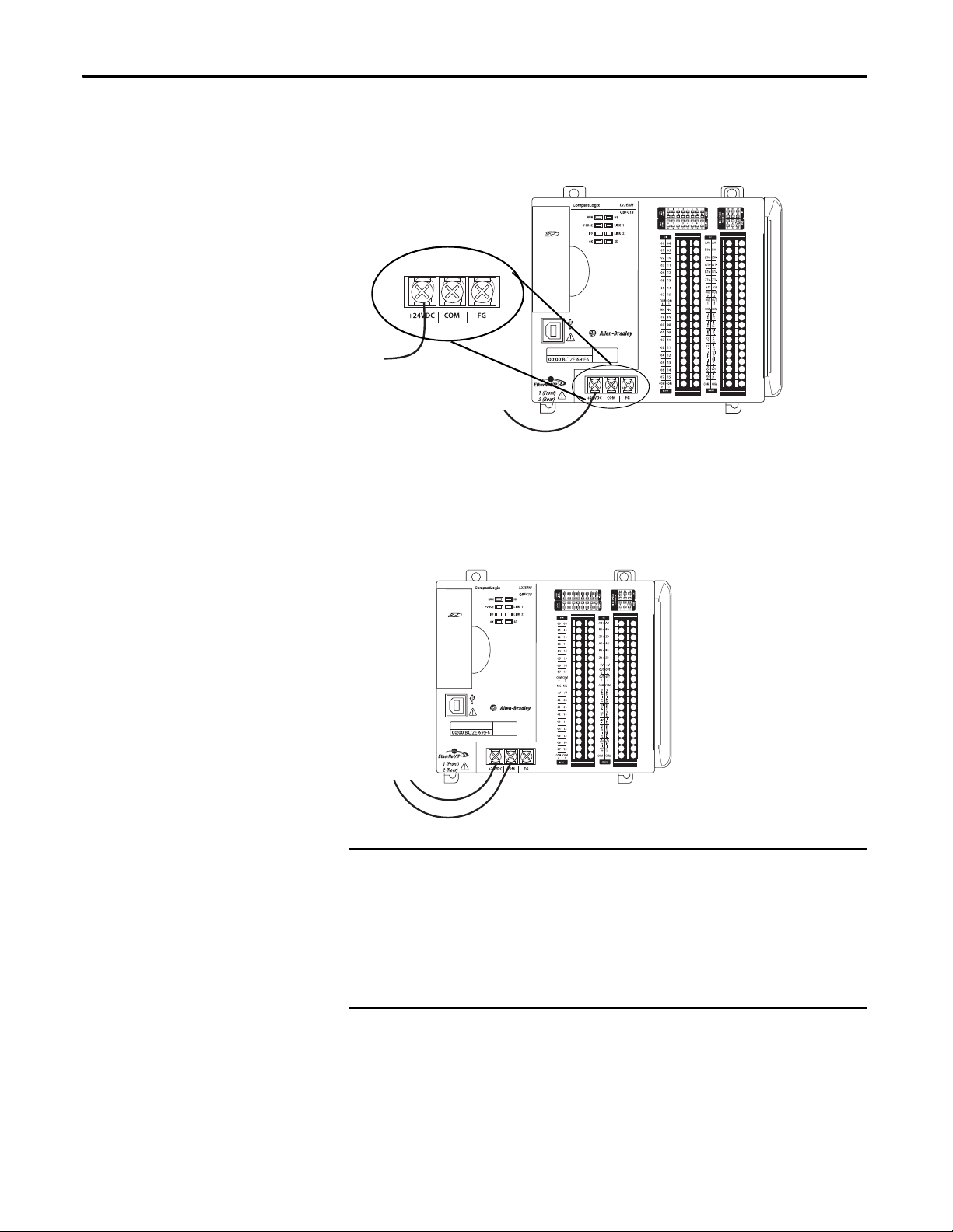
Chapter 2 Install the CompactLogix 5370 L2 Controller
IMPORTANT
5. Connect the wire from the 24VDC+ terminal on the external 24V DC
power source to the +24VDC terminal on the controller.
6. Strip 8 mm (0.31 in) insulation from the end of the wire that you connect
to the COM terminal on the controller.
7. Connect the wire from the 24V DC- terminal on the external 24V DC
power source to the COM terminal on the controller.
If your application requires a power control device, for example, a switch or
relay, between the external power supply and the embedded power supply of
the CompactLogix 5370 L2 controller to control when the controller is powered,
you must install the power control device at the +24V DC terminal on the
controller.
If you install the power control device at the COM terminal, the
CompactLogix 5370 L2 controller cannot power up or power down properly.
52 Rockwell Automation Publication 1769-UM021G-EN-P - October 2015

Install the CompactLogix 5370 L2 Controller Chapter 2
IMPORTANT
The following graphic shows an external 24V DC power source that is connected
to a CompactLogix 5370 L2 controller.
When you remove power from the CompactLogix 5370 L2 controller to cycle
power, the OK status indicator of the controller remains lit briefly as the
controller passes through its shutdown sequence.
Do not reapply power from the external power supply to the embedded power
supply of the CompactLogix 5370 L2 controller until after the OK status
indicator of the controller is off.
Connect to the Controller via
a USB Cable
The controller has a USB port that uses a Type B receptacle. The port is USB
2.0-compatible and operates at 12 Mbps.
Use a USB cable to connect your computer to the USB port. With this
connection, you can upgrade firmware and download programs to the controller
directly from your computer.
ATTENTION: The USB port is intended only for temporary local
programming purposes and not intended for permanent connection.
The USB cable is not to exceed 3.0 m (9.84 ft) and must not contain hubs.
WARNING: Do not use the USB port in hazardous locations.
Plug the USB cable into the CompactLogix 5370 L2 controller.
Rockwell Automation Publication 1769-UM021G-EN-P - October 2015 53
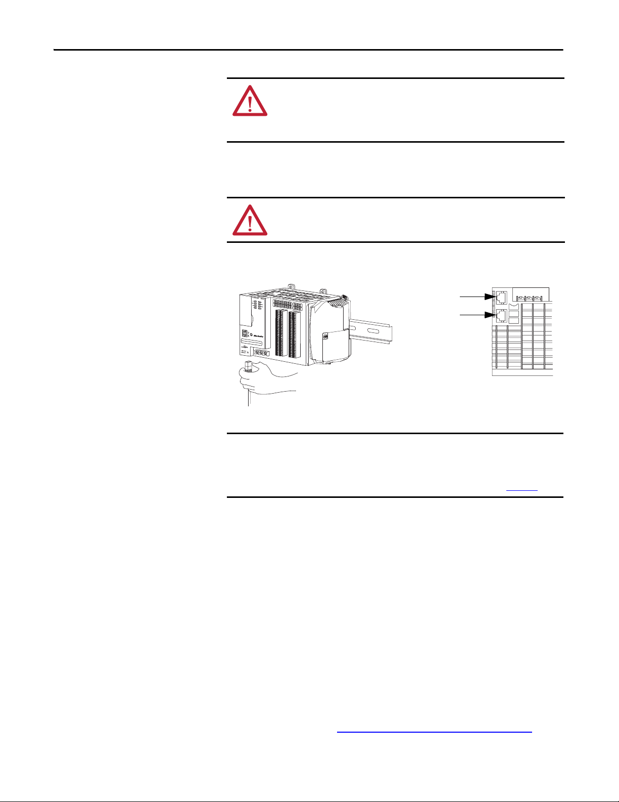
Chapter 2 Install the CompactLogix 5370 L2 Controller
IMPORTANT
Port 1 - Fron t
Port 2 - Bac k
Bottom of Controller
Connect the Controller to an
EtherNet/IP Network
WARNING: If you connect or disconnect the communication cable with
power applied to this module or any device on the network, an electrical arc
can occur. This could cause an explosion in hazardous location installations.
Be sure that power is removed or the area is nonhazardous before proceeding.
Connect the RJ45 connector of the Ethernet cable to one of the Ethernet ports
on the controller. The ports are on the bottom of the controller.
ATTENTION: Do not plug a DH-485 network cable or a NAP cable into the
Ethernet port. Undesirable behavior and/or damage to the port can result.
This example shows how to connect the controller to the network through one
port. Depending on the network topology of your application, you can connect
both ports of the controller to the EtherNet/IP network.
For more information on EtherNet/IP network topologies, see page 127
.
Connecting to Different EtherNet/IP Network Topologies
CompactLogix 5370 L2 controllers have embedded switch technology and two
EtherNet/IP ports that let you use it in various EtherNet/IP network topologies:
• Device-level ring network topology - Both ports on the controller are
connected to the network.
• Linear network topology - Both ports on the controller are connected to
the network.
• Star network topology - One port on the controller is connected to
the network.
There are connection and configuration requirements for each EtherNet/IP
network topology.
For more information, see EtherNet/IP Network Topologies
on page 127.
54 Rockwell Automation Publication 1769-UM021G-EN-P - October 2015

Chapter 3
Install the CompactLogix 5370 L3 Controller
Top ic Pag e
Before You Begin 58
Install the Secure Digital Card 60
Install the System 62
Connec t to the Controller via a USB Cab le 72
Connect the Controller to an EtherNet/IP Network 73
ATTENTION: Environment and Enclosure
This equipment is intended for use in a Pollution Degree 2 industrial environment, in overvoltage Category II applications (as defined
in IEC 60664-1), at altitudes up to 2000 m (6562 ft) without derating.
This equipment is considered Group 1, Class A industrial equipment according to IEC/CISPR 11. Without appropriate precautions,
there may be difficulties with electromagnetic compatibility in residential and other environments due to conducted and radiated
disturbances.
This equipment is supplied as open-type equipment. It must be mounted within an enclosure that is suitably designed for those
specific environmental conditions that will be present and appropriately designed to prevent personal injury resulting from
accessibility to live parts. The enclosure must have suitable flame-retardant properties to prevent or minimize the spread of flame,
complying with a flame spread rating of 5VA, V2, V1, V0 (or equivalent) if nonmetallic. The interior of the enclosure must be
accessible only by the use of a tool. Subsequent sections of this publication may contain additional information regarding specific
enclosure type ratings that are required to comply with certain product safety certifications.
In addition to this publication, see the following:
• Industrial Automation Wiring and Grounding Guidelines, publication 1770-4.1
• NEMA 250 and IEC 60529, as applicable, for explanations of the degrees of protection provided by enclosures
, for additional installation requirements
Rockwell Automation Publication 1769-UM021G-EN-P - October 2015 55
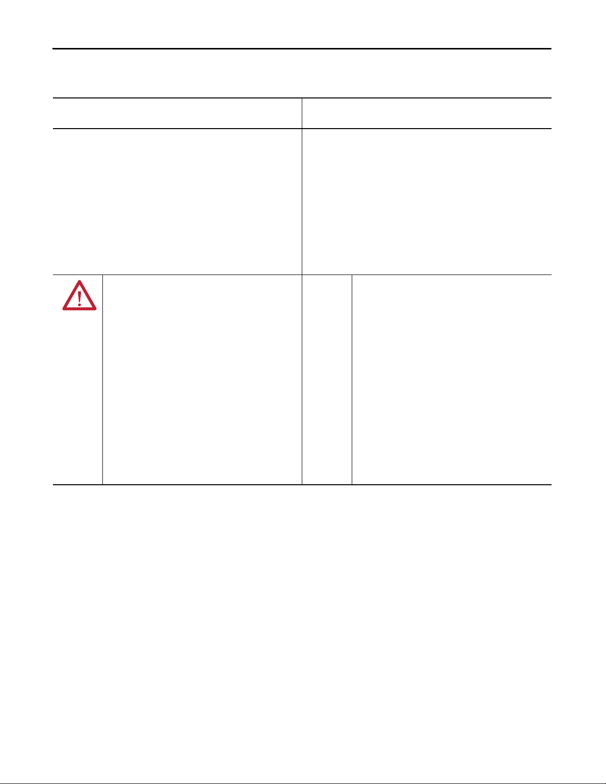
Chapter 3 Install the CompactLogix 5370 L3 Controller
North American Hazardous Location Approval
The following information applies when operating this equipment in
hazardous locations.
Produc ts marked "CL I, DIV 2, GP A, B, C, D" are suitable for use in Class
I Division 2 Groups A, B, C, D, Hazardous Locations and nonhazardous
locations only. Each product is supplied with markings on the rating
nameplate indicating the hazardous location temperature code.
When combining products within a system, the most adverse
temperature code (lowest "T" number) may be used to help
determine the overall temperature code of the system. Combinations
of equipment in your system are subject to investigation by the local
Authority Having Jurisdiction at the time of installation.
WARNING: EXPLOSION HAZARD -
• Do not disconnect equipment unless power has
been removed or the area is known to be
nonhazardous.
• Do not disconnect connections to this equipment
unless power has been removed or the area is
known to be nonhazardous. Secure any external
connections that mate to this equipment by using
screws, sliding latches, threaded connectors, or
other means provided with this product.
• Substitution of components may impair suitability
for Class I, Division 2.
• If this product contains batteries, they must only
be changed in an area known to be nonhazardous.
Informations sur l’utilisation de cet équipement en environnements
dangereux.
Les produits marqués "CL I, DIV 2, GP A, B, C, D" ne conviennent qu'à
une utilisation en environnements de Classe I Division 2 Groupes A, B,
C, D dangereux et non dangereux. Chaque produit est livré avec des
marquages sur sa plaque d'identification qui indiquent le code de
température pour les environnements dangereux. Lorsque plusieurs
produits sont combinés dans un système, le code de température le
plus défavorable (code de température le plus faible) peut être utilisé
pour déterminer le code de température global du système. Les
combinaisons d'équipements dans le système sont sujettes à
inspection par les autorités locales qualifiées au moment de
l'installation.
AVERTISSEMENT: RISQUE D’EXPLOSION –
• Couper le courant ou s'assurer que
l'environnement est classé non dangereux avant
de débrancher l'équipement.
• Couper le courant ou s'assurer que
l'environnement est classé non dangereux avant
de débrancher les connecteurs. Fixer tous les
connecteurs externes reliés à cet équipement à
l'aide de vis, loquets coulissants, connecteurs
filetés ou autres moyens fournis avec ce produit.
• La substitution de composants peut rendre cet
équipement inadapté à une utilisation en
environnement de Classe I, Division 2.
• S'assurer que l'environnement est classé non
dangereux avant de changer les piles.
56 Rockwell Automation Publication 1769-UM021G-EN-P - October 2015

Install the CompactLogix 5370 L3 Controller Chapter 3
European Hazardous Location Approval
The following applies when the product bears the Ex Marking.
This equipment is intended for use in potentially explosive atmospheres as defined by European Union Directive 94/9/EC and has been found to
comply with the Essential Health and Safety Requirements relating to the design and construction of Category 3 equipment intended for use in
Zone 2 potentially explosive atmospheres, given in Annex II to this Directive.
Compliance with the Essential Health and Safety Requirements has been assured by compliance with EN 60079-15 and EN 60079-0.
ATTENTION: This equipment is not resistant to sunlight or other sources of UV radiation.
WARNING:
• This equipment must be installed in an enclosure providing at least IP54 protection when applied in Zone 2 environments.
• This equipment shall be used within its specified ratings defined by Rockwell Automation®.
• Provision shall be made to prevent the rated voltage from being exceeded by transient disturbances of more than 40% when
applied in Zone 2 environments.
• Secure any external connections that mate to this equipment by using screws, sliding latches, threaded connectors, or other
means provided with this product.
• Do not disconnect equipment unless power has been removed or the area is known to be nonhazardous.
• Enclosure must be marked with the following: "Warning - Do not open when energized." After installation of equipment into
the enclosure, access to termination compartments shall be dimensioned so that conductors can be readily connected.
ATTENTION: Prevent Electrostatic Discharge
This equipment is sensitive to electrostatic discharge, which can cause internal damage and affect normal operation. Follow these
guidelines when you handle this equipment:
• Touch a grounded object to discharge potential static.
• Wear an approved grounding wriststrap.
• Do not touch connectors or pins on component boards.
• Do not touch circuit components inside the equipment.
• Use a static-safe workstation, if available.
• Store the equipment in appropriate static-safe packaging when not in use.
Rockwell Automation Publication 1769-UM021G-EN-P - October 2015 57
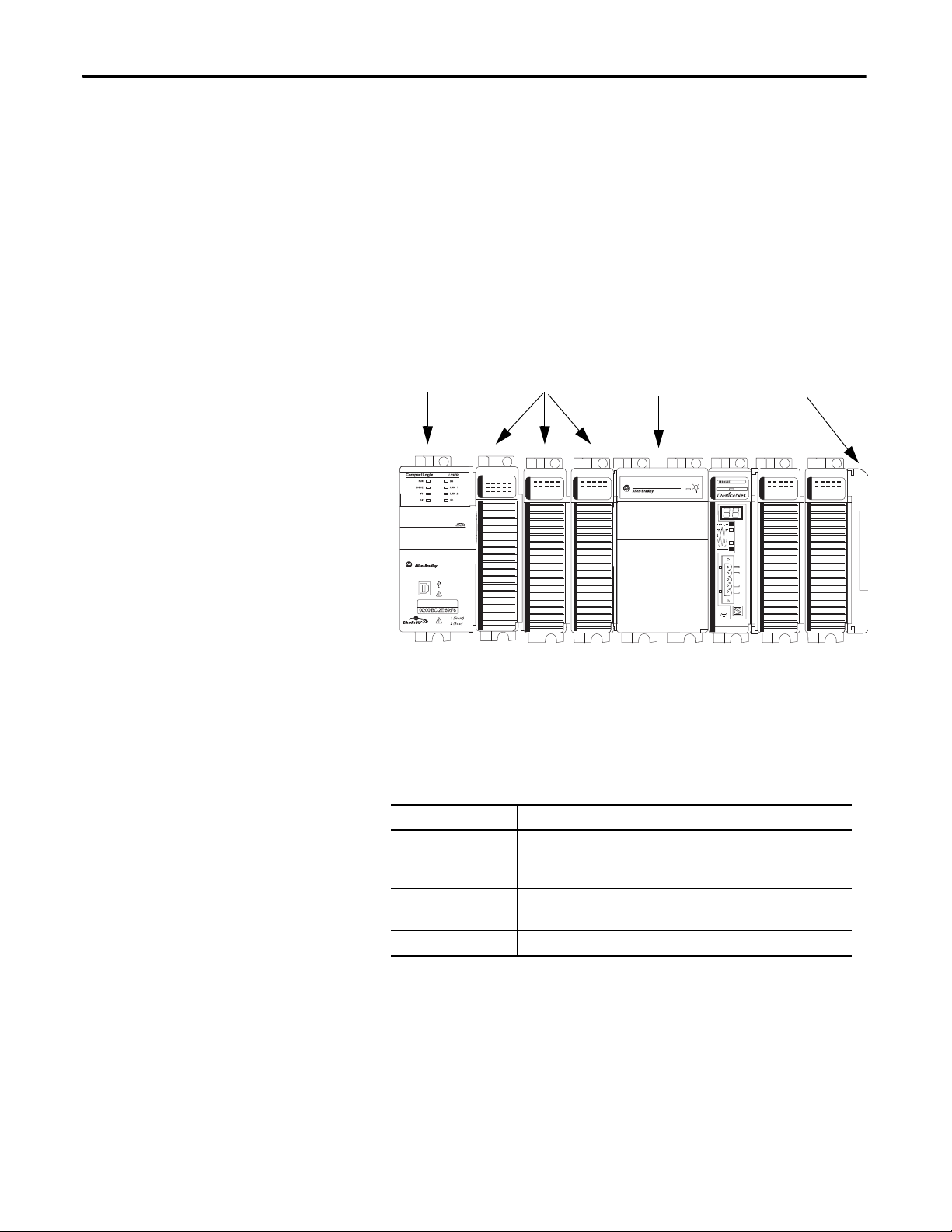
Chapter 3 Install the CompactLogix 5370 L3 Controller
1769-L33ERM
Compact I/ O
End CapPower Supply
Before You Begin
Consider the following when planning your CompactLogix™ 5370 L3
control system:
• The controller is the leftmost device in the system.
• Only one controller can be used on a local 1769 CompactBus. The
controller supports the local bank and up to two more banks.
• The controller has a power supply distance rating of four. This rating
means that the controller must be within four slots of the power supply.
You can install as many as three modules between the power supply and
the controller, as shown in the following graphic.
• The controllers support this many local expansion modules across multiple
I/O banks.
Cat. No. Local Expansion Modules Supported, max
1769- L30ER
1769-L30ERM
1769-L30ER-NSE
1769-L33ER
1769-L33ERM
1769-L36ERM 30
8
16
• Each I/O bank requires its own power supply.
58 Rockwell Automation Publication 1769-UM021G-EN-P - October 2015
Install the CompactLogix 5370 L3 Controller Chapter 3
IMPORTANT
• You must terminate the end of the last bank in a CompactLogix 5370 L3
control system. You can terminate a bank at the left or right end of the
bank dependent upon your system design.
A 1769-ECx end cap is required to terminate the end of the last bank in
the control system.
For example, if a CompactLogix 5370 L3 control system uses one bank,
you must use a 1769-ECR right end cap to terminate the right end of the
bank.
For graphics of CompactLogix 5370 L3 control systems that use one bank
or multiple banks, see Mount the System
on page 65.
ATTENTION: The CompactLogix 5370 L3 control systems do not support
removal and insertion under power (RIUP). These events occur while the
CompactLogix system is under power:
• Any break in the connection between the power supply and the
controller, for example, removing the power supply, controller, or an I/O
module, can subject the logic circuitry to transient conditions above the
normal design thresholds and can result in damage to system
components or unexpected behavior.
• Removing an end cap or an I/O module faults the controller and can
also result in damage to system components.
CompactLogix 5370 L3 Controller Parts
These parts are included in the box when you order your controller:
• Controller - Specific catalog number varies by order
• 1784-SD1 Secure Digital (SD) card with 1 GB of memory storage
A 1784-SD2 SD card with 2 GB of memory storage, or more 1784-SD1
SD cards, are also available if you need more memory.
The life expectancy of nonvolatile media is dependent on the number
of write cycles that are performed. Nonvolatile media use a wear
leveling technique or technology for prolonging the service life, but
avoid frequent writes.
Avoid frequent writes when logging data. We recommend that you log
data to a buffer in the memory of your controller and limit the number
of times data is written to removable media.
Rockwell Automation Publication 1769-UM021G-EN-P - October 2015 59

Chapter 3 Install the CompactLogix 5370 L3 Controller
Unlocked Locked
Installation Summary
Install the Secure
Digital Card
To install a CompactLogix 5370 L3 controller, follow these steps.
• Install the Secure Digital Card
• Install the System
• Connect to the Controller via a USB Cable.
• Connect the Controller to an EtherNet/IP Network
The CompactLogix 5370 L3 controllers ship from the factory with the
1784-SD1 SD card installed.
Complete these steps to reinstall an SD card that has been removed from the
controller back into the controller or to install a new SD card into the controller.
We recommend that you leave the SD card in the controller, even when it is not
used. If the controller experiences a Major Non-recoverable Fault, extended fault
information is saved to the card.
WARNING: When you insert or remove the Secure Digital (SD) Card while
power is on, an electrical arc can occur. This could cause an explosion in
hazardous location installations.
Be sure that power is removed or the area is nonhazardous before proceeding.
.
1. Verify that the SD card is locked or unlocked according to your preference.
Consider the following when deciding to lock the card before installation:
– If the card is unlocked, the controller can write data to it or read data
from it.
60 Rockwell Automation Publication 1769-UM021G-EN-P - October 2015

Install the CompactLogix 5370 L3 Controller Chapter 3
2. Open the door for the SD card.
3. Insert the SD card into the SD card slot.
You can install the SD card in only one orientation. The beveled corner is
at the top. An orientation logo is printed on the card.
If you feel resistance when inserting the SD card, pull it out and change the
orientation.
4. Gently press the card until it clicks into place.
5. Close the SD card door.
We recommend that you keep the SD card door closed during normal system
operation. For more information on using the SD card, see Use a Secure Digital
Card on page 297.
Rockwell Automation Publication 1769-UM021G-EN-P - October 2015 61

Chapter 3 Install the CompactLogix 5370 L3 Controller
Install the System
Complete the following steps to install the CompactLogix 5370 L3
control system.
• Assemble the System
• Mount the System
• Ground the System
• Connect Power to the Control System
Assemble the System
You can attach an adjacent Compact I/O™ module or 1769 Compact I/O power
supply to a CompactLogix 5370 L3 controller before or after mounting. For
mounting instructions, see Ground the System
Controller on a Panel on page 70.
ATTENTION: Do not remove or replace this module while power is applied.
Interruption of the backplane can result in unintentional operation or
machine motion.
on page 69 or Mount the
WARNING: Remove power before removing or inserting this module. If you
insert or remove the module while backplane power is on, an electrical arc can
occur. This could cause an explosion in hazardous location installations.
Be sure that power is removed or the area is nonhazardous before proceeding.
This section describes how to assemble a local bank.
Complete these steps to install the controller. This example describes how to
attach a 1769 Compact I/O power supply to the controller.
1. Verify that line power is disconnected.
2. Make sure that the bus lever of the 1769 Compact I/O power supply is in
the unlocked position, that is, leaning to the right.
62 Rockwell Automation Publication 1769-UM021G-EN-P - October 2015

Install the CompactLogix 5370 L3 Controller Chapter 3
IMPORTANT
Tongue-and-groove Slots
3. Use the upper and lower tongue-and-groove slots to secure the controller
and power supply together.
4. Move the power supply back along the tongue-and-groove slots until the
bus connectors align with each other.
5. Use your fingers or a small screwdriver to push the bus lever of the power
supply back slightly to clear the positioning tab.
6. Move the bus lever of the power supply fully to the left until it clicks;
making sure that it locks.
7. If your system does not use any local expansion modules, use the tongueand-groove slots described earlier to attach a 1769-ECR Compact I/O end
cap terminator to the last module in the system.
You must install an end cap onto the right side of the
CompactLogix 5370 L3 controller system either at the end of the
controller or at the end of any local expansion modules that can be
installed onto the controller.
8. Wire the 1769 Compact I/O power supply according to the directions in
the Compact I/O Expansion Power Supplies installation instructions,
publication 1769-IN028
If you are using local expansion modules, see Local Expansion Modules
.
on
page 238.
Rockwell Automation Publication 1769-UM021G-EN-P - October 2015 63

Chapter 3 Install the CompactLogix 5370 L3 Controller
TIP
TIP
1
3
2
Install the Removable Terminal Block
To remove the terminal block, loosen the upper and lower retaining screws. The
terminal block backs away from the module as you remove the screws. When
replacing the terminal block, torque the retaining screws to 0.46 N
.
Item Description
1 Wiring the finger-safe terminal block
2 Lower retaining screws
3 Uppe r retaining s crews
•m (4.1 lb•in).
Wire the Terminal Block
When wiring the terminal block, keep the finger-safe cover in place.
1. Loosen the terminal screws to be wired.
2. Route the wire under the terminal pressure plate.
You can use the bare wire or a spade lug. The terminals accept a 6.35 mm
(0.25 in.) spade lug.
The terminal screws are non-captive. You can use a ring lug [maximum 6.35
mm (0.25 in.) o.d. with a 3.53 mm (0.139 in.) minimum i.d. (M3.5)] with the
module.
3. Tighten the terminal screw making sure the pressure plate secures the wire.
Recommended torque when tightening terminal screws is 0.68 N•m
(6 lb•in).
If you need to remove the finger-safe cover, insert a screwdriver into one of the
square wiring holes and gently pry the cover off. If you wire the terminal block
with the finger-safe cover removed, you cannot put it back on the terminal
block because of wires in the way.
64 Rockwell Automation Publication 1769-UM021G-EN-P - October 2015

Install the CompactLogix 5370 L3 Controller Chapter 3
Wire Size and Terminal Screw Torque
Each terminal accepts one or two wires with the following restrictions.
Wire Type Wire Size Terminal Screw Torque Retaining Screw Torque
Solid Cu-90 °C (194 °F) #14…#22 AWG 0.68 N•m (6 lb•in) 0.46 N•m (4.1 lb•in)
Stranded Cu-90 °C (194 °F) #16…#22 AWG 0.68 N•m (6 lb•in) 0.46 N•m (4.1 lb•in)
Mount the System
You can mount a CompactLogix 5370 L3 control system on a DIN rail or on
apanel.
ATTENTION: During panel or DIN rail mounting of all devices, be sure that all
debris (such as metal chips or wire strands) is kept from falling into the
controller. Debris that falls into the controller could cause damage while the
controller is energized.
A CompactLogix 5370 L3 control system must be mounted so that the modules
are horizontal to each other. If you separate modules into multiple banks, the
banks can be vertical or horizontal to each other.
Figure 1
shows example systems with local expansion modules included.
Rockwell Automation Publication 1769-UM021G-EN-P - October 2015 65

Chapter 3 Install the CompactLogix 5370 L3 Controller
1769-CRLx Cable
Horizontal Orientation
Vertical Orientation
Bank 1 Bank 2
Bank 1
Bank 2
Bank 3
1769-CRLx Cable
1769-CRRx Cable
Figure 1 - Example CompactLogix 5370 L3 Control Systems
66 Rockwell Automation Publication 1769-UM021G-EN-P - October 2015
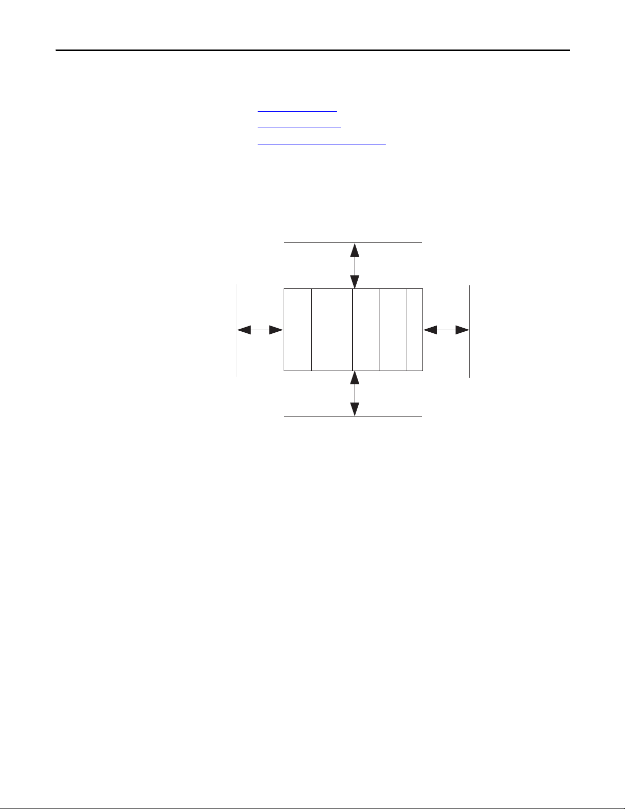
Install the CompactLogix 5370 L3 Controller Chapter 3
Bottom
Side Side
Top
CompactLogix 5370 L3 Controller
Power Supply
Compact I/O Module
End Cap
50 mm
(2 in.)
50 mm
(2 in.)
50 mm
(2 in.)
50 mm
(2 in.)
Compac t I/O Mod ule
Before you mount a CompactLogix 5370 L3 control system, consider
the following:
• Minimum Spacing
• System Dimensions
• Power Supply Distance Rating
Minimum Spacing
Maintain spacing from enclosure walls, wireways, and adjacent equipment. Allow
50 mm (2 in.) of space on all sides, as shown. This spacing provides ventilation
and electrical isolation.
Rockwell Automation Publication 1769-UM021G-EN-P - October 2015 67
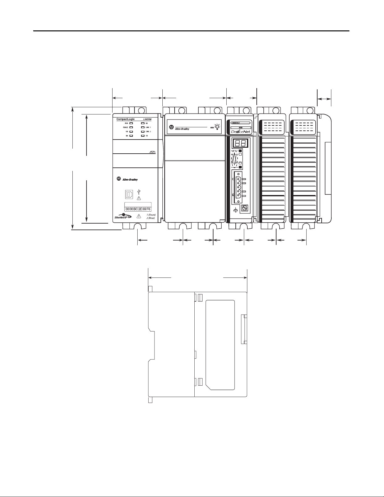
Chapter 3 Install the CompactLogix 5370 L3 Controller
132 mm
(5.20 in.)
118 mm
(4.65 in.)
55 mm
(2.17 in.)
70 mm
(2.76 in.)
35 mm
(1.38 in.)
35 mm
(1.38 in.)
35 mm
(1.38 in.)
35 mm
(1.38 in.)
35 mm
(1.38 in.)
52.5 mm
(2.07 in.)
105 mm
(4.13 in.)
18 mm
(0.71 in.)
System Dimensions
This graphic shows the system dimensions.
68 Rockwell Automation Publication 1769-UM021G-EN-P - October 2015
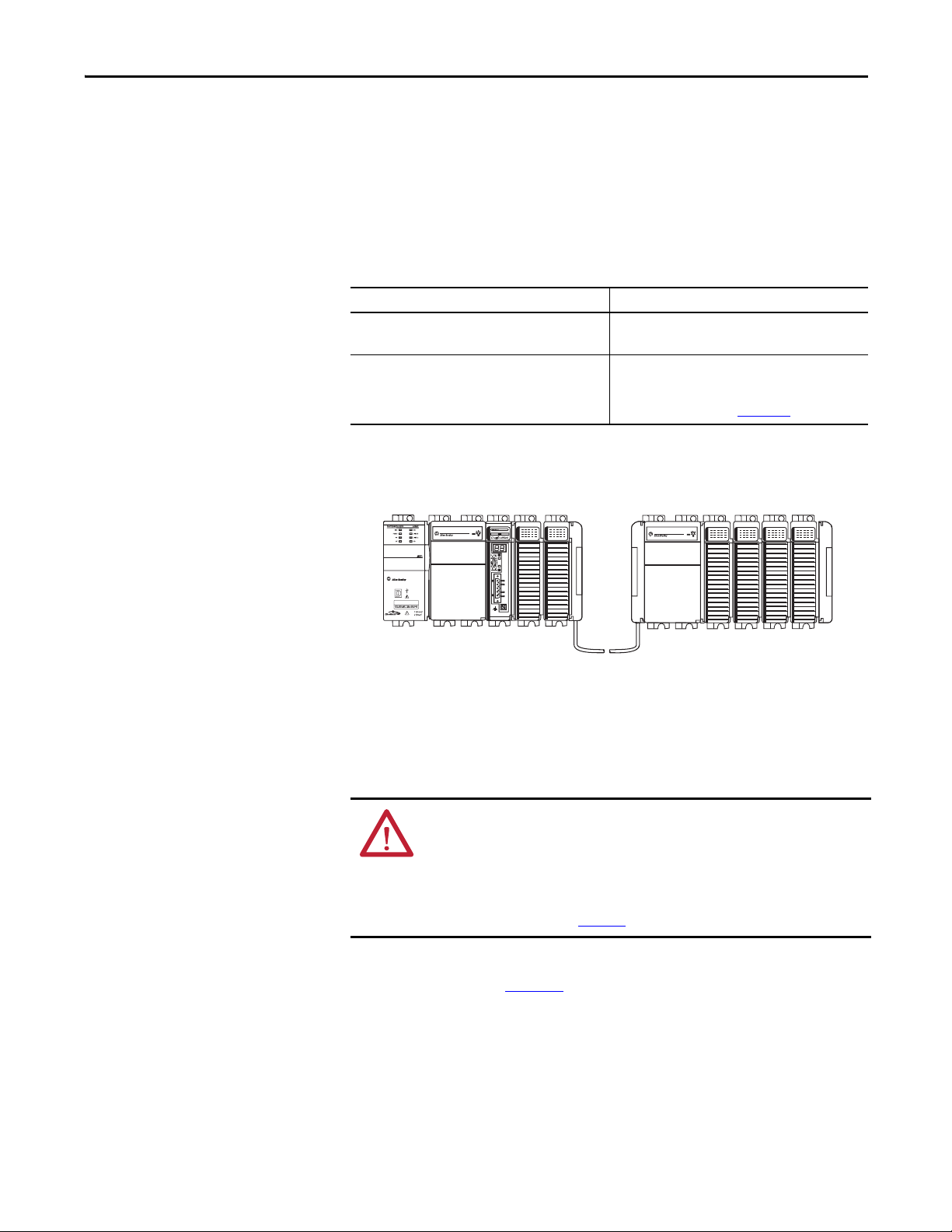
Install the CompactLogix 5370 L3 Controller Chapter 3
1769-CRLx Cable
Bank 1 Bank 2
Power Supply Distance Rating
CompactLogix 5370 L3 controllers and the Compact I/O modules have power
supply distance ratings. Power supply distance ratings determine how many slots
in a bank that a device can be from the power supply.
For example, a product with a power supply distance rating of four can only have
up to three slots between it and the power supply.
Device Power Supply Distance Rating
CompactLogix 5370 L3 controller
1769 Compact I/O DeviceNet scanner
Compact I/O module 4…8, depending on module
CompactLogix 5370 L3 controllers must be the leftmost device in the control
system, and the system only enables up to three modules between the controller
and the power supply. This graphic shows an example configuration.
4
For more information about the power supply distance
rating for a Compact I/O module, see CompactLogix
Selection Guide, publication 1769-SG001
Rockwell Automation Publication 1769-UM021G-EN-P - October 2015 69
Ground the System
ATTENTION: This product is intended to be mounted to a well-grounded
mounting surface such as a metal panel. Additional grounding connections
from the power supply's mounting tabs or DIN rail (if used) are not required
unless the mounting surface cannot be grounded.
See Industrial Automation Wiring and Grounding Guidelines, Rockwell
Automation publication 1770-4.1
For more information, see the Industrial Automation Wiring and Grounding
Guidelines, publication 1770-4.1
.
, for additional information.

Chapter 3 Install the CompactLogix 5370 L3 Controller
IMPORTANT
TIP
TIP
Mount the Controller on a Panel
Use two M4 or #8 pan head screws to mount the controller. Mounting screws are
required on many modules. Use this procedure to use the assembled modules as a
template for drilling holes in the panel.
Due to module mounting hole tolerance, it is important to follow these
procedures.
1. On a clean work surface, assemble no more than three modules.
2. Using the assembled modules as a template, carefully mark the center of all
module-mounting holes on the panel.
3. Return the assembled modules to the clean work surface, including any
previously mounted modules.
4. Drill and tap the mounting holes for the recommended M4 or #8 screw.
5. Place the modules back on the panel and check for proper hole alignment.
The grounding plate, that is, where you install the mounting screws,
grounds the module when it is panel-mounted.
6. Use the mounting screws to attach the modules to the panel.
If you are mounting more modules, mount only the last one of this group
and put the others aside. This reduces remounting time when you are
drilling and tapping the next group of modules.
7. Repeat steps 1
…6 for any remaining modules.
70 Rockwell Automation Publication 1769-UM021G-EN-P - October 2015
Install the CompactLogix 5370 L3 Controller Chapter 3
Mount the Controller on the DIN Rail
You can mount the controller on the following DIN rails:
• EN 50 022 - 35 x 7.5 mm (1.38 x 0.30 in.)
• EN 50 022 - 35 x 15 mm (1.38 x 0.59 in.)
ATTENTION: This product is grounded through the DIN rail to chassis ground.
Use zinc-plated yellow-chromate steel DIN rail to assure proper grounding.
The use of other DIN rail materials (for example, aluminum or plastic) that
can corrode, oxidize, or are poor conductors, can result in improper or
intermittent grounding. Secure DIN rail to mounting surface approximately
every 200 mm (7.8 in.) and use end-anchors appropriately.
1. Before mounting the controller on a DIN rail, close the DIN rail latches of
the controller.
2. Press the DIN rail mounting area of the controller against the DIN rail.
The latches momentarily open and lock into place.
Connect Power to the Control System
Connect power to the CompactLogix 5370 L3 control system that is based on
the 1769 Compact I/O power supply your application uses. For more
information on connecting power to your CompactLogix 5370 L3 control
system, see the Compact I/O Expansion Power Supplies Installation Instructions,
publication 1769-IN028
.
Rockwell Automation Publication 1769-UM021G-EN-P - October 2015 71
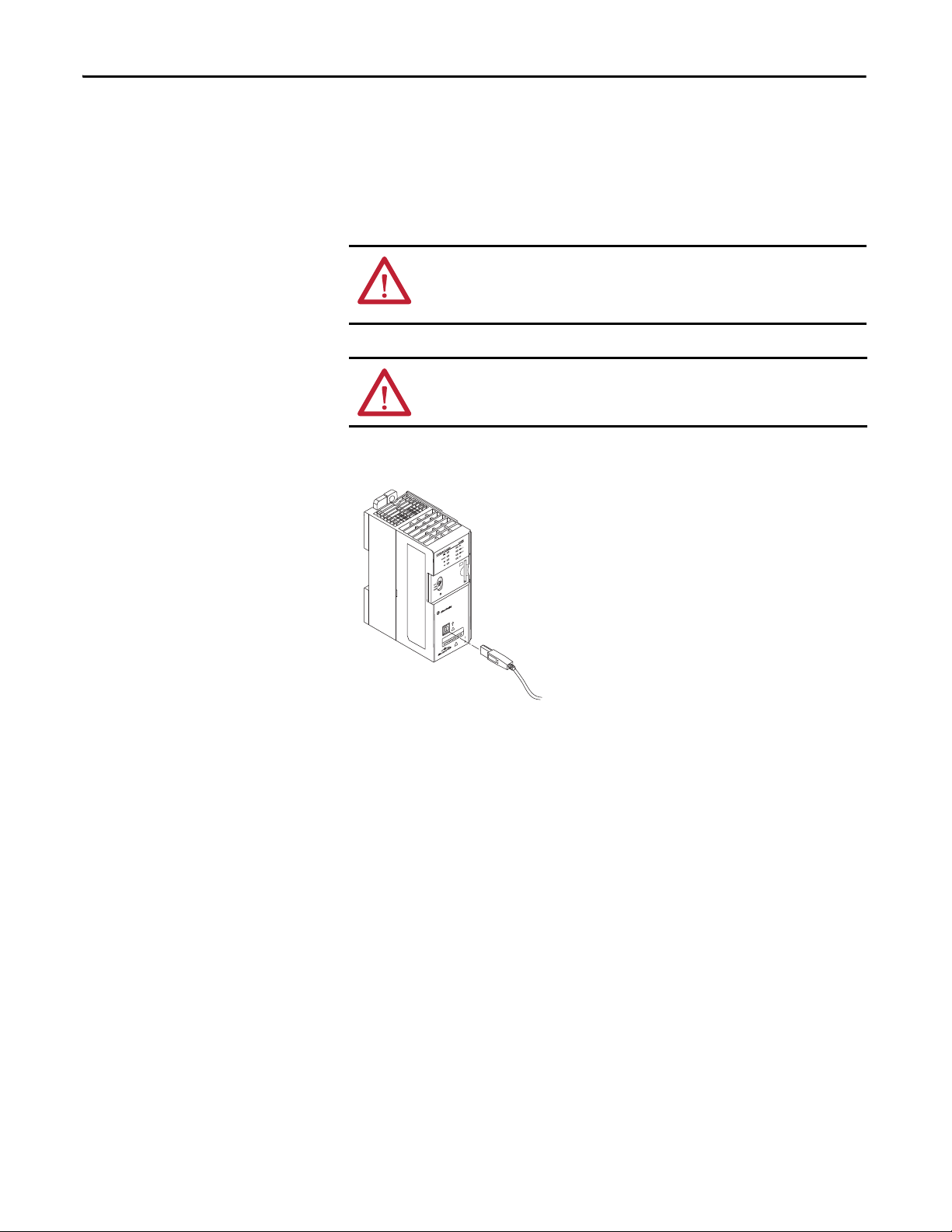
Chapter 3 Install the CompactLogix 5370 L3 Controller
Connect to the Controller
via a USB Cable
The controller has a USB port that uses a Type B receptacle. The port is USB
2.0-compatible and operates at 12 Mbps.
Use a USB cable to connect your computer to the USB port. With this
connection, you can upgrade firmware and download programs to the controller
directly from your computer.
ATTENTION: The USB port is intended only for temporary local programming
purposes and not intended for permanent connection.
The USB cable is not to exceed 3.0 m (9.84 ft) and must not contain hubs.
WARNING: Do not use the USB port in hazardous locations.
Plug the USB cable into the CompactLogix 5370 L3 controller as shown.
72 Rockwell Automation Publication 1769-UM021G-EN-P - October 2015

Install the CompactLogix 5370 L3 Controller Chapter 3
IMPORTANT
Bottom of Controller
Port 1 - Front
Port 2 - Rear
Connect the Controller to an
EtherNet/IP Network
WARNING: If you connect or disconnect the communication cable with
power applied to this module or any device on the network, an electrical arc
can occur. This could cause an explosion in hazardous location installations.
Be sure that power is removed or the area is nonhazardous before proceeding.
Connect the RJ45 connector of the Ethernet cable to one of the Ethernet ports
on the controller. The ports are on the bottom of the controller.
ATTENTION: Do not plug a DH-485 network cable or a NAP cable into the
Ethernet port. Undesirable behavior or damage to the port can result.
This example shows how to connect the controller to the network through one
port. Depending on the Ethernet network topology of your application, you can
connect both ports of the controller to the EtherNet/IP network.
For more information on EtherNet/IP network topologies, see page 127
.
Rockwell Automation Publication 1769-UM021G-EN-P - October 2015 73

Chapter 3 Install the CompactLogix 5370 L3 Controller
Connecting to Different EtherNet/IP Network Topologies
The CompactLogix 5370 L3 controllers have embedded switch technology and
two EtherNet/IP ports that let you use it in different EtherNet/IP
network topologies:
• Device-level Ring network topology - Both ports on the controller are
connected to the network with requirements about how the connections
are made.
• Linear network topology - Both ports on the controller are connected to
the network with requirements about how the connections are made.
• Star network topology - One port on the controller is connected to
the network.
For more information, see EtherNet/IP Network Topologies
on page 127.
74 Rockwell Automation Publication 1769-UM021G-EN-P - October 2015
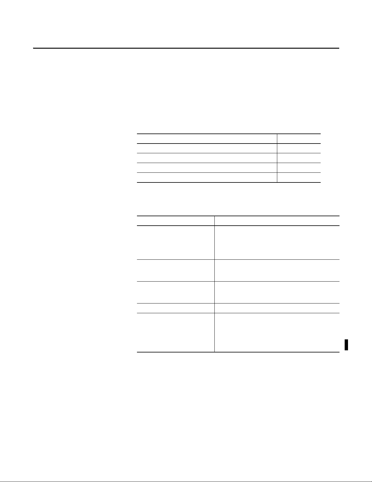
Chapter 4
Complete Software Tasks Required at
CompactLogix 5370 Controller Installation
Top ic Pag e
Set the IP Address of a Controller 77
Change the IP Address of a Controller 94
Load the Controller Firmware 98
Select the Operating Mode of the Controller 112
To complete the tasks that are described in this chapter, you must have the
software that is described in the following table installed on your computer.
Software Required Version
RSLinx Classic 2.59.00 or later
CompactLogix 5370 L2 controllers require RSLinx Classic software,
version 2.59.01 or later.
The1769-L19ER-BB1B controller requires RSLinx Classic software,
version 3.74.00
RSLogix 5000® 20 - For CompactLogix 5370 controllers using firmware revision 20.
RSLogix 5000 software does not support the 1769-L19ER-BB1B
controller.
Studio 5000® environment 21 or later - For CompactLogix™ 5370 controllers using firmware
BOOTP-DHCP ser ver Most current version is installed with RSLinx Classi c software installation
ControlFLASH™ Installed with the installation of one of the following:
revisio n 21 or later.
28 or later - For the 1769-L19ER-BB1B controller.
• RSLogix 5000 software, version 20
• Studio 5000 environment, version 21 or later
• Studio 5000 environment, version 28 or later for 1769-L19ER-BB1B
controllers
CompactLogix 5370 controllers require a network Internet Protocol (IP) address
to operate on an EtherNet/IP network.
Rockwell Automation Publication 1769-UM021G-EN-P - October 2015 75

Chapter 4 Complete Software Tasks Required at CompactLogix 5370 Controller Installation
IMPORTANT
The IP address uniquely identifies the controller. The IP address is in the form
xxx.xxx.xxx.xxx where each xxx is a number from 000
exceptions for reserved values. These numbers are examples of reserved values
you cannot use:
• 000.xxx.xxx.xxx
• 127.xxx.xxx.xxx
• 224 to 255.xxx.xxx.xxx
Some other values are reserved based on an application-by-application basis.
You can complete one of these tasks dependent on system conditions:
•Set the IP address for a controller that does not have one assigned.
•Change the IP address for a controller that has an IP address that is
assigned to it.
…254 with some
CompactLogix 5370 controllers have two EtherNet/IP ports to connect to an
EtherNet/IP network. The ports carry the same network traffic as part of the
embedded switch of the controller. However, the controller uses only one IP
address.
76 Rockwell Automation Publication 1769-UM021G-EN-P - October 2015

Complete Sof tware Tasks Required at Compa ctLogix 5370 Controller Installation Chapter 4
IMPORTANT
Set the IP Address of a
Controller
You must set the IP address of a CompactLogix 5370 controller when the
controller powers up for the first time, that is, when commissioning the controller
for the first time. You are not required to set an IP address each time that power is
cycled to the controller.
You can use these tools to set the IP address of a CompactLogix 5370 controller:
• Bootstrap Protocol (BOOTP) server
• Dynamic Host Configuration Protocol (DHCP) server
• RSLinx Classic software
• Studio 5000 Logix Designer® application
• SD card
Each tool has connection requirements to set the IP address of the controller
via that tool. For example, your computer must be connected to the controller
via a USB cable to set the initial IP address of the controller with RSLinx Classic
software or the application.
Figure 2
controller on a power cycle during initial installation or after operation has
begun.
describes how to set the IP address of your CompactLogix 5370
Rockwell Automation Publication 1769-UM021G-EN-P - October 2015 77

Chapter 4 Complete Software Tasks Required at CompactLogix 5370 Controller Installation
Control ler Power Cycle
Controller has an IP address.
Does controller have IP
address in nonvolatile
memory or is an SD card
installed that is
configured to load a
project (with an IP
address) to the controller
on a power cycle?
Yes
No
Is controller
BOOTP- enabled?
Yes
No
Use USB driver in
RSLinx Classic or the
application to set
the address.
Computer
connected to
controller via
USB?
No
Yes
Use BOOTP server to
set the IP address.
Is controller
DHCP- enabled?
Use DHCP to set
the IP address.
Connect computer to
controller via USB.
Yes
No
Figure 2 - Set the IP address on a power cycle during initial installation or after operation has
begun
78 Rockwell Automation Publication 1769-UM021G-EN-P - October 2015

Complete Sof tware Tasks Required at Compa ctLogix 5370 Controller Installation Chapter 4
Use the BOOTP Server to Set the IP Address of the Controller
Bootstrap Protocol (BOOTP) is a protocol that enables the controller to
communicate with a BOOTP server. The server can be used to assign an IP
address. You can use the BOOTP server to set an IP address for your
CompactLogix 5370 controller.
Consider these points when using the BOOTP server:
• The BOOTP server is installed automatically when you install RSLinx
Classic or the Studio 5000 environment on your computer. The BOOTP
server sets an IP address and other Transmission Control Protocol (TCP)
parameters.
• A CompactLogix 5370 controller ships from the factory without an IP
address and BOOTP-enabled.
• This section describes how to use a Rockwell Automation® BOOTP/
DHCP server. If you use another BOOTP/DHCP server, contact your
network administrator to verify that you are using it correctly.
• To use the BOOTP server, your computer and the controller must be
connected to the same EtherNet/IP network.
• If the controller is BOOTP-disabled, you cannot use the BOOTP server
to set the IP address.
There are two conditions in which the CompactLogix 5370 controllers use the
BOOTP servers to set the IP address of the controller:
•Initial powerup - Because the CompactLogix 5370 controller ships with
BOOTP-enabled, when it is first powered up, the controller sends a
request for an IP address on the EtherNet/IP network. You can use the
BOOTP server to set the IP address, as described later in this section.
• Powerup after controller operation has begun - When controller power
is cycled after operation has begun, the BOOTP/DHCP server sets the IP
address if one of these conditions exists:
– Controller is BOOTP-enabled - You set the IP address manually with
the BOOTP server.
– Controller is DHCP-enabled - The IP address is set automatically via
the DHCP server.
Rockwell Automation Publication 1769-UM021G-EN-P - October 2015 79

Chapter 4 Complete Software Tasks Required at CompactLogix 5370 Controller Installation
IMPORTANT
1769-L18ERM-BB1B Controller 1769-L24ER-QB1B Controller
1769-L33ER Controller
IMPORTANT
Access the BOOTP/DHCP utility from one of these locations:
• Start>Programs>Rockwell Software®>BOOTP-DHCP Server
If you have not installed the utility, you can download and install it from
http://www.ab.com/networks/ethernet/bootp.html
• Tools directory on the programming software installation CD
Before you start the BOOTP/DHCP utility, make sure that you have the hardware (MAC) address of the controller. The hardware
address is on the front of the controller and uses an address in a format similar to the following:
00:00:BC:2E:69:F6
.
Complete these steps to set the IP address of the controller with the
BOOTP/DHCP server.
To use the BOOTP server, your computer and the controller must be connected
to the same EtherNet/IP network.
1. Start the BOOTP/DHCP software.
80 Rockwell Automation Publication 1769-UM021G-EN-P - October 2015

Complete Sof tware Tasks Required at Compa ctLogix 5370 Controller Installation Chapter 4
2. From the Tools menu, choose Network Settings.
3. Type the Subnet Mask of the network.
The Gateway address, Primary or Secondary DNS address, and Domain
Name fields are optional.
4. Click OK.
The Request History panel appears with the hardware addresses of all
devices that issue BOOTP requests. This process can take some time to
complete.
5. Select the appropriate module.
Rockwell Automation Publication 1769-UM021G-EN-P - October 2015 81

Chapter 4 Complete Software Tasks Required at CompactLogix 5370 Controller Installation
IMPORTANT
6. Click Add to Relation List.
The New Entry dialog box appears.
7. Type an IP Address, Hostname, and Description for the controller.
8. Click OK.
9. To assign this configuration to the controller, wait for the controller to
appear in the Relation List panel and select it.
10. Click Disable BOOTP/DHCP.
When power is cycled, the controller uses the assigned configuration and
does not issue a BOOTP request.
If you do not click Disable BOOTP/DHCP on a power cycle, the host
controller clears the current IP configuration and begins sending
BOOTP requests again.
82 Rockwell Automation Publication 1769-UM021G-EN-P - October 2015
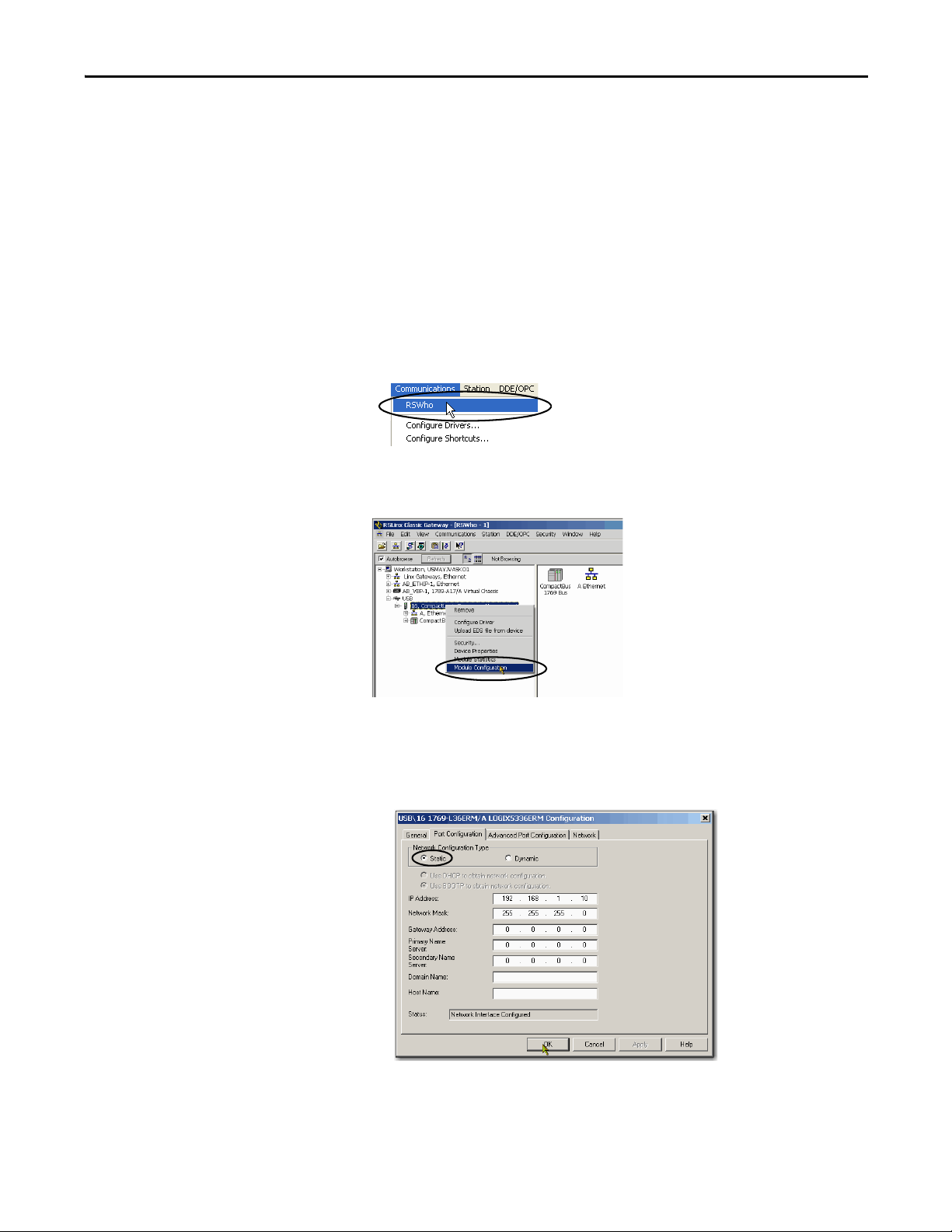
Complete Sof tware Tasks Required at Compa ctLogix 5370 Controller Installation Chapter 4
If you click Disable BOOTP/DHCP and it does not disable BOOTP/DHCP,
use RSLinx or the Studio 5000 environment to disable BOOTP/DHCP.
To disable BOOTP/DHCP from RSLinx, perform the following:
1. Make sure that a USB cable is connected to your computer and the
controller.
2. Start RSLinx Classic software.
After several seconds, an RSWho dialog box appears.
3. If no RSWho dialog box appears, from the Communications pull-down
menu, choose RSWho.
4. Navigate to the USB network
5. Right-click on the controller and choose Module Configuration.
6. Click the Port Configuration tab.
7. From the Network Configuration Type, click Static to disable BOOTP/
DHCP.
8. Click OK.
Rockwell Automation Publication 1769-UM021G-EN-P - October 2015 83
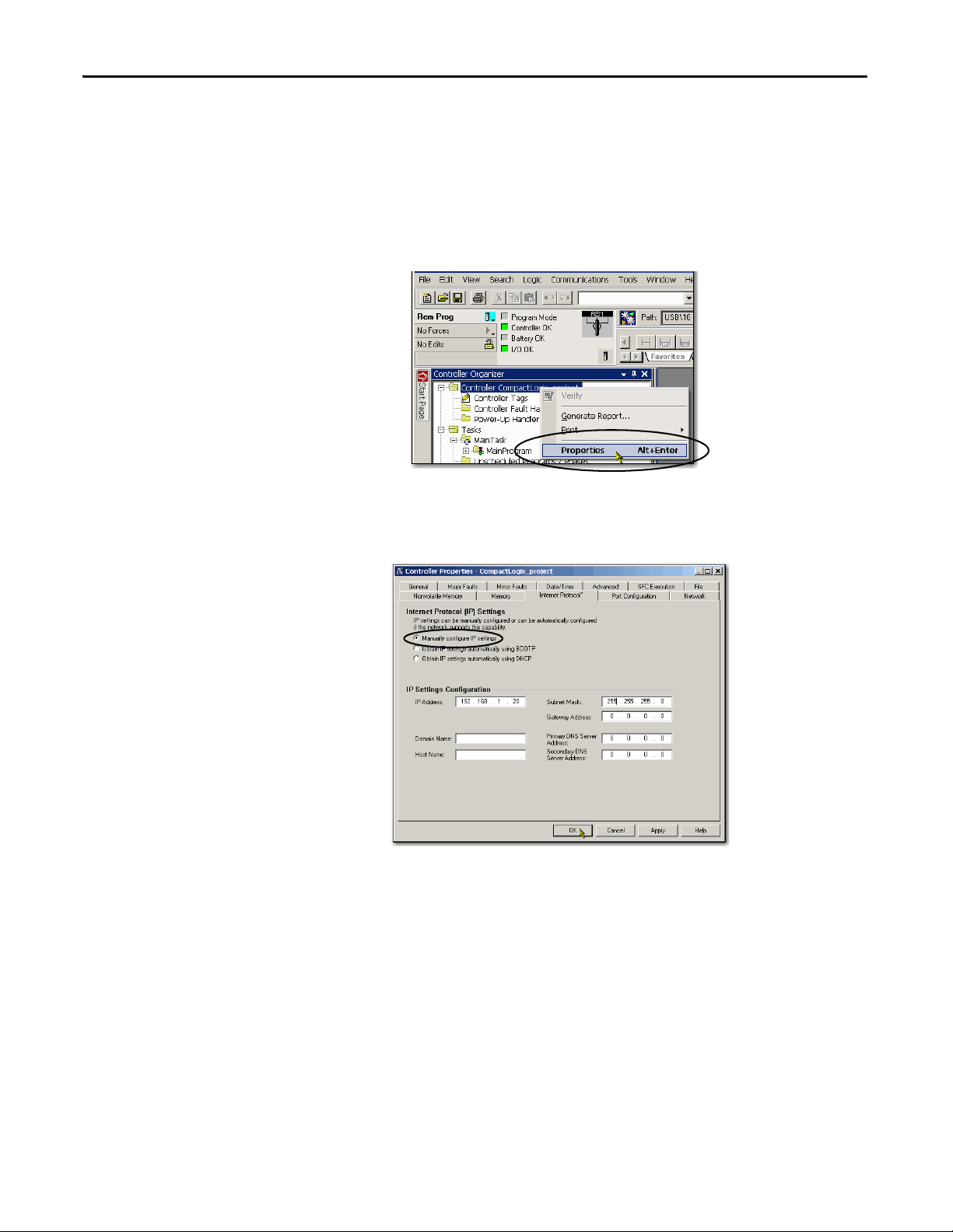
Chapter 4 Complete Software Tasks Required at CompactLogix 5370 Controller Installation
To disable BOOTP/DHCP from the Studio 5000 environment, perform the
following:
1. Start the application.
2. Open the project.
3. Right-click on the controller and choose Properties.
4. On the Controller Properties dialog box, click the Internet Protocol tab.
5. Click Manually configure IP settings.
6. Click OK.
7. When prompted to confirm the IP address setting, click Yes.
84 Rockwell Automation Publication 1769-UM021G-EN-P - October 2015
Complete Sof tware Tasks Required at Compa ctLogix 5370 Controller Installation Chapter 4
Using DHCP Software
Dynamic Host Configuration Protocol (DHCP) software automatically assigns
IP addresses to client stations logging on to a TCP/IP network. DHCP is based
on BOOTP and maintains some backward compatibility. The main difference is
that BOOTP allows for manual configuration (static), while DHCP allows for
both static and dynamic allocation of network addresses and configurations to
newly attached modules.
Be cautious when using DHCP software to configure a module. A BOOTP
client, such as the EtherNet/IP communication modules, can start from a DHCP
server only if the DHCP server is written to handle BOOTP queries. This
requirement is specific to the DHCP software package used. Consult your
system administrator to see if a DHCP package supports BOOTP commands
and manual IP allocation.
ATT EN TI ON : The EtherNet/IP communication module must be assigned a fixed
network address. The IP address of this module must not be dynamically
provided.
Failure to observe this precaution may result in unintended machine motion or loss
of process control.
Rockwell Automation Publication 1769-UM021G-EN-P - October 2015 85
Chapter 4 Complete Software Tasks Required at CompactLogix 5370 Controller Installation
Use the DHCP Server to Set the IP Address of the Controller
Dynamic Host Configuration Protocol (DHCP) server automatically assigns IP
addresses to client stations logging on to a TCP/IP network. DHCP is based on
BOOTP and maintains some backward compatibility. The main difference is
that BOOTP manual configuration (static), while DHCP enables static and
dynamic allocation of network addresses and configurations to newly attached
controllers.
Be cautious when using the DHCP server to configure a controller. A BOOTP
client, such as the CompactLogix 5370 controllers, can start from a DHCP
server only if the DHCP server is written to handle BOOTP queries. This
requirement is specific to the DHCP server used. Consult your system
administrator to see if a DHCP server supports BOOTP commands and manual
IP allocation.
AT TE NT IO N: Assign the CompactLogix 5370 controllers a fixed network
address. The IP address of this controller is not to be dynamically provided.
Failure to observe this precaution can result in unintended machine motion or
loss of process control.
If you use the Rockwell Automation BOOTP or DHCP server in an uplinked
subnet where a DHCP server exists, a controller can procure an address from the
enterprise server before the Rockwell Automation utility even sees the controller.
Disconnect from the uplink to set the address and configure the controller to
retain its static address before reconnecting to the uplink, if necessary.
86 Rockwell Automation Publication 1769-UM021G-EN-P - October 2015
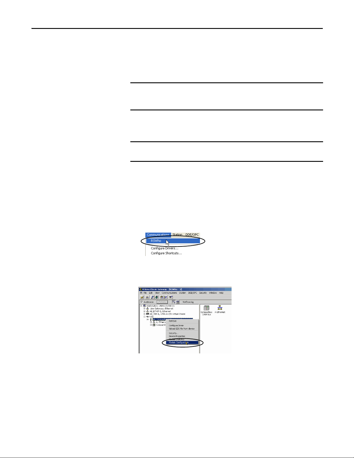
Complete Sof tware Tasks Required at Compa ctLogix 5370 Controller Installation Chapter 4
IMPORTANT
IMPORTANT
Use RSLinx Software to Set the IP Address of the Controller
You can use RSLinx software to set the IP address of the CompactLogix 5370
controller.
To set the IP address, that is, assign an IP address to a controller that does not
have one, for a CompactLogix 5370 controller via RSLinx software, you must be
connected to your controller via the USB port.
Complete these steps to set the IP address of the controller with RSLinx
software.
These steps show a 1769-L36ERM controller. The same steps also apply to all
CompactLogix 5370 controllers with slight variations in screens.
1. Make sure that a USB cable is connected to your computer and the
controller.
2. Start RSLinx software.
After several seconds, an RSWho dialog box appears.
3. If no RSWho dialog box appears, from the Communications pull-down
menu, choose RSWho.
The RSWho dialog box appears and includes the USB driver.
4. Right-click the EtherNet/IP module and choose Module Configuration.
The Module Configuration dialog box appears.
Rockwell Automation Publication 1769-UM021G-EN-P - October 2015 87
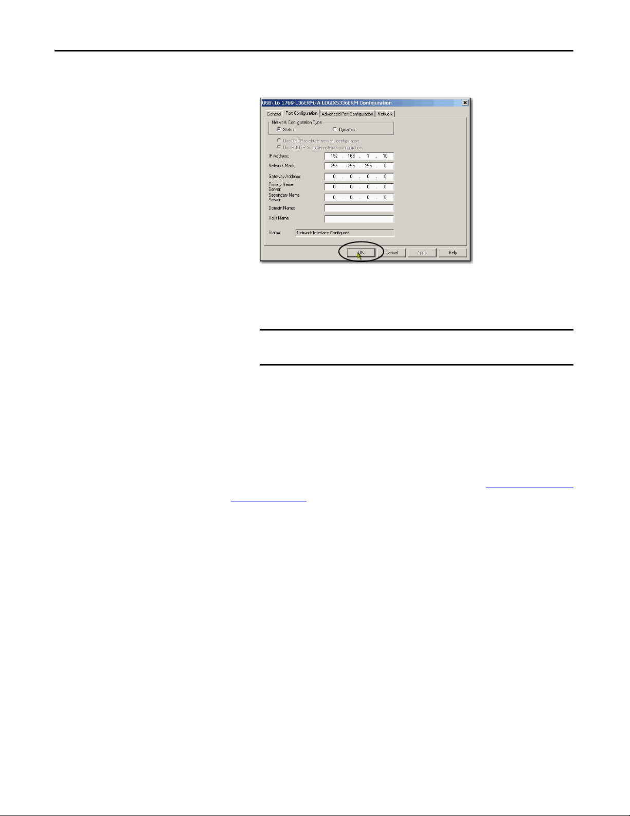
Chapter 4 Complete Software Tasks Required at CompactLogix 5370 Controller Installation
IMPORTANT
5. Click the Port Configuration tab.
6. For Network Configuration Type, select Static to assign this configuration
to the port.
If you click Dynamic, on a power cycle, the controller clears the
current IP configuration and starts to send BOOTP requests.
7. Type the new IP address and Network Mask.
8. Click OK.
As with all configuration changes, if desired, make sure that you are using the SD
card in a way that does not overwrite the IP address at the next controller power
cycle.
For more information on using the SD card, see Chapter 12, Use a Secure Digital
Card on page 297.
88 Rockwell Automation Publication 1769-UM021G-EN-P - October 2015
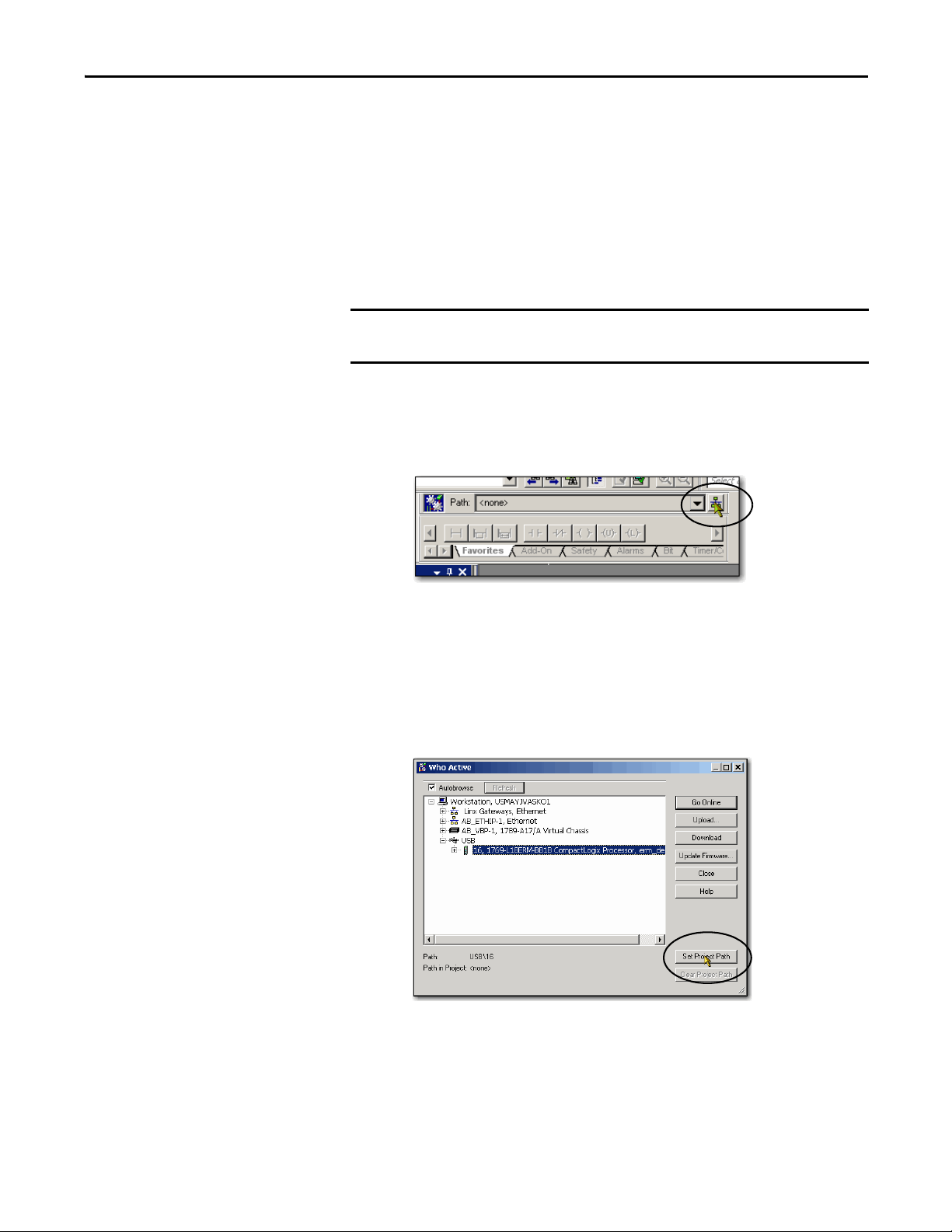
Complete Sof tware Tasks Required at Compa ctLogix 5370 Controller Installation Chapter 4
IMPORTANT
Use the Studio 5000 Environment to Set the IP Address of the
Controller
You can use Logix Designer application to set the IP address of a CompactLogix
5370 controller. To set the IP address via the application, you must be connected
to your controller via the USB port.
Complete these steps to set the IP address of the controller.
These steps show a 1769-L18ERMBB1B controller. The same steps also apply to
all CompactLogix 5370 controllers with slight variations in screens.
1. Start the application.
2. Set the Project Path.
a. Click RSWho.
The RSWho dialog box appears.
b. Navigate over the USB network and select the
CompactLogix 5370 controller.
c. Click Set Project Path.
Rockwell Automation Publication 1769-UM021G-EN-P - October 2015 89

Chapter 4 Complete Software Tasks Required at CompactLogix 5370 Controller Installation
3. Click Download.
4. Click Download again.
The new project is downloaded to the controller and the project goes
online, in Remote Program or Program mode.
90 Rockwell Automation Publication 1769-UM021G-EN-P - October 2015
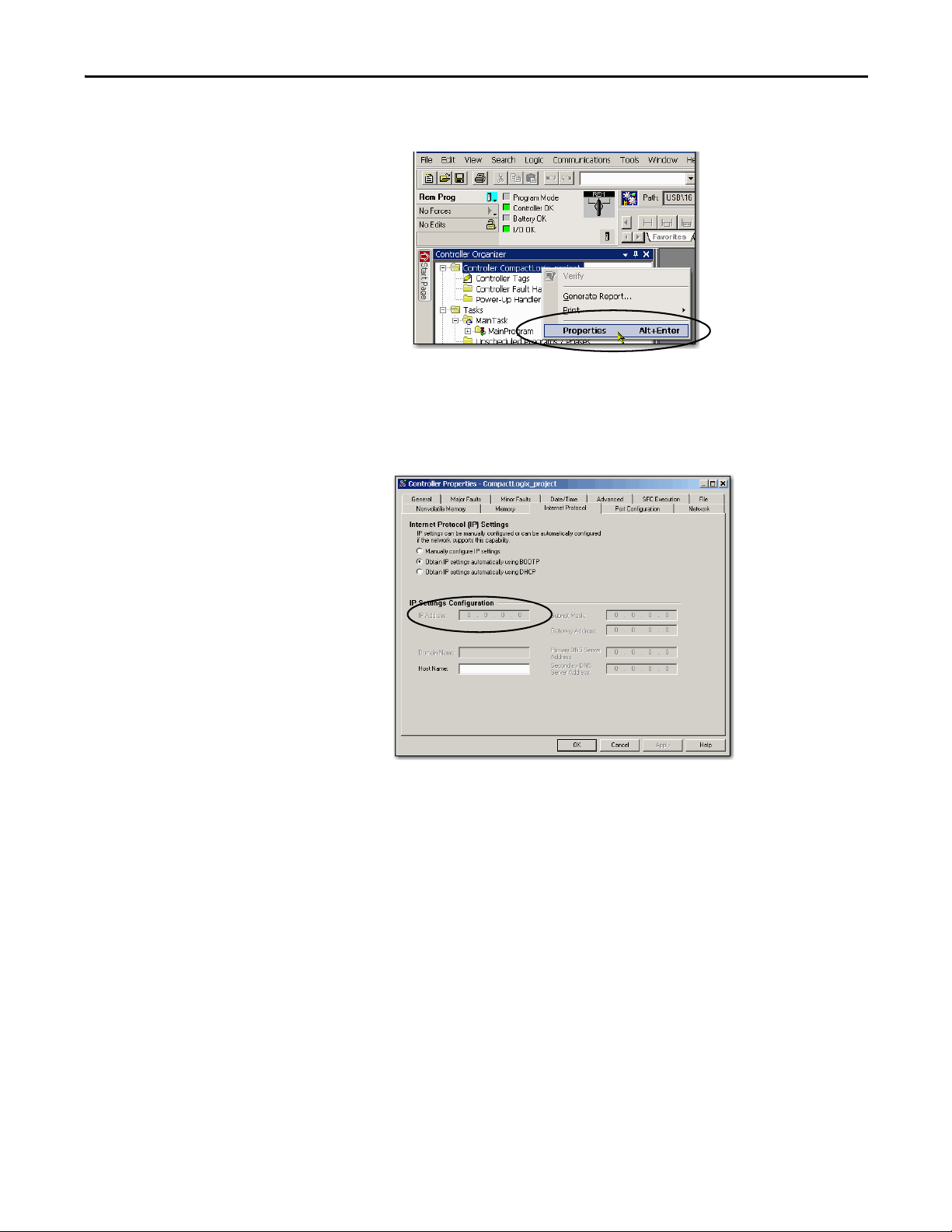
Complete Sof tware Tasks Required at Compa ctLogix 5370 Controller Installation Chapter 4
5. Right-click the controller name and choose Properties.
6. On the Controller Properties dialog box, click the Internet Protocol tab.
The IP Settings Configuration values show that the controller has no IP
address that is assigned to it.
7. Click Manually configure IP settings.
Rockwell Automation Publication 1769-UM021G-EN-P - October 2015 91
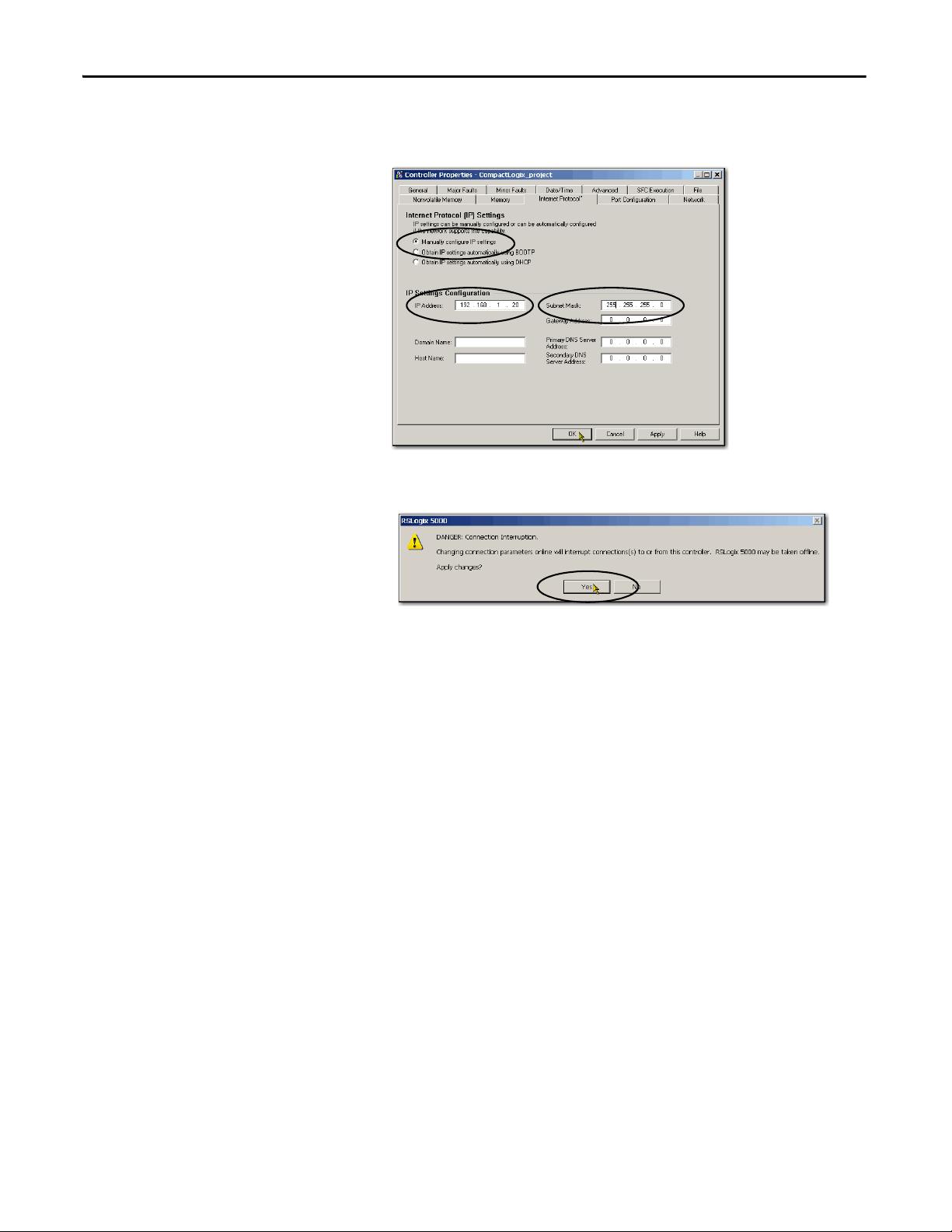
Chapter 4 Complete Software Tasks Required at CompactLogix 5370 Controller Installation
8. Enter desired IP address and other configuration information and
click OK.
9. When prompted to confirm the IP address setting, click Yes.
The controller now uses the newly set IP address.
92 Rockwell Automation Publication 1769-UM021G-EN-P - October 2015

Complete Sof tware Tasks Required at Compa ctLogix 5370 Controller Installation Chapter 4
IMPORTANT
Use the SD Card to Set the IP Address of the Controller
You can use an SD card to set the IP address for a CompactLogix 5370 controller.
Using the SD card to set the IP address eliminates the need for software to
complete this task.
To set the IP address from an SD card, software is not required during the
power-up process. However, you must have previously saved the project to the
SD card.
The IP address of the CompactLogix 5370 controller is automatically configured
at power-up as long as you have configured an IP address, stored the program
onto a controller, and set the SD card to the Load Image parameter set to On
Power Up.
The option to set the IP address of a CompactLogix 5370 controller via an SD
card at power-up is only one part of the process to load an entire project to the
controller from the SD card.
Use this option carefully. For example, the SD card can contain a desirable IP
address as part of an undesirable project, for example, a project that is older
than the project currently used on the controller.
These requirements apply when using the SD card to set the IP address on a
CompactLogix 5370 controller:
• A project must be stored on the SD card.
• The project that is stored on the SD card is configured with the Load
Image parameter set to On Power Up.
For more information on using the SD card, see Chapter 12, Use a Secure Digital
Card on page 297.
Rockwell Automation Publication 1769-UM021G-EN-P - October 2015 93

Chapter 4 Complete Software Tasks Required at CompactLogix 5370 Controller Installation
IMPORTANT
Change the IP Address of a
Controller
You can change the IP address of a CompactLogix 5370 controller after system
operation has begun. In this case, the controller has an IP address that is assigned
to it, but you must change that IP address.
You can use these tools to change the IP address of a controller:
• RSLinx Classic software
• Studio 5000 Logix Designer® application
• SD card
You cannot use any of these tools to change a the IP address of a controller:
• Bootstrap Protocol (BOOTP) server
• Dynamic Host Configuration Protocol (DHCP) server
Consider these factors when you determine how to change the IP address of a
controller:
• Network isolation from, or integration into, the plant/enterprise network
• Network size - For large, isolated networks, it can be more convenient and
safer to use a BOOTP/DHCP server rather than
the Studio 5000 environment or RSLinx Classic software. A BOOTP/
DHCP server limits the possibility of duplicate IP address assignment.
However, you can only use the BOOTP/DHCP server to set the IP
address of the controller and not to change it. If you decide to change the
IP address of the controller and want to use a BOOTP/DHCP server to
limit the possibility of duplicate IP address assignment, you must first clear
the IP address.
After clearing the IP address, use the steps that are described at Use the
BOOTP Server to Set the IP Address of the Controller on page 79 or Use
the DHCP Server to Set the IP Address of the Controller on page 86 to
set the IP address of the controller.
• Company policies and procedures that deal with plant floor network
installation and maintenance
• Level of involvement by IT personnel in plant-floor network installation
and maintenance
• Type of training that is offered to control engineers and maintenance
personnel
94 Rockwell Automation Publication 1769-UM021G-EN-P - October 2015

Complete Sof tware Tasks Required at Compa ctLogix 5370 Controller Installation Chapter 4
IMPORTANT
IMPORTANT
Change the Network IP Address with RSLinx Classic Software
The steps in Use RSLinx Software to Set the IP Address of the Controller on
page 87 describe how to assign an IP address for a CompactLogix 5370
controller that does not have an IP address.
The steps in this section describe how to change the IP address on a
CompactLogix 5370 controller that has an IP address that is assigned to it.
The graphics in this section show how to change the IP address for a
1769-L36ERM controller. The same steps also apply to all other CompactLogix
5370 controllers with slight variations in screens.
1. Right-click the controller and choose Module Configuration.
2. Click the Port Configuration tab when the Module Configuration dialog
box appears.
The controller has an IP address and Network Configuration Type.
3. Type a new IP address and make any other desired changes.
4. To assign this configuration to the controller, click Static in the Network
Configuration Type section of the dialog box.
If you click Dynamic, on a power cycle, the controller clears the
current IP configuration and starts to send BOOTP or DHCP
requests, depending on the controller configuration.
5. Click OK.
Rockwell Automation Publication 1769-UM021G-EN-P - October 2015 95

Chapter 4 Complete Software Tasks Required at CompactLogix 5370 Controller Installation
IMPORTANT
Change the Network IP Address with Logix Designer Application
The steps in Use the Studio 5000 Environment to Set the IP Address of the
Controller on page 89 describe how to assign an IP address for a
CompactLogix 5370 controller that does not have an IP address.
The steps in this section describe how to change the IP address on a
CompactLogix 5370 controller that has an IP address that is assigned to it.
You can change the IP address of a CompactLogix 5370 controller via Logix
Designer application over a USB or EtherNet/IP network connection.
The graphics in this section show how to change the IP address for a
1769-L18ERM-BB1B controller over a USB connection. The same steps also
apply to all other CompactLogix 5370 controllers with slight variations in
screens.
1. Verify that your computer is connected to the controller.
2. Verify that your project is online.
3. Right-click the controller name and choose Properties.
You can also right-click the Ethernet node in the I/O Configuration
section and choose Properties. The Controller Properties dialog box
appears on the Internet Protocol tab.
96 Rockwell Automation Publication 1769-UM021G-EN-P - October 2015

Complete Sof tware Tasks Required at Compa ctLogix 5370 Controller Installation Chapter 4
IMPORTANT
4. Change the IP address of the controller.
5. Make other changes where necessary.
6. Click OK.
Change the Network IP Address with an SD Card
You can use an SD card to change the IP address for a CompactLogix 5370
controller when controller power is cycled. Using the SD card to change the IP
address removes the need for software to complete this task.
To set the IP address from an SD card, software is not required during the
power-up process. However, you must have previously saved the project to the
SD card.
These requirements apply when using the SD card to change the IP address on a
CompactLogix 5370 controller:
• A project is stored on the SD card.
• The project that is stored on the SD card includes another IP address for
the CompactLogix 5370 controller than the IP address currently in use on
the physical controller that houses the SD card.
• The project that is stored on the SD card is configured with the Load
Image parameter set to On Power Up.
• Power is cycled to the controller with the SD card installed.
For more information on using the SD card, see Chapter 12, Use a Secure Digital
Card on page 297.
Rockwell Automation Publication 1769-UM021G-EN-P - October 2015 97

Chapter 4 Complete Software Tasks Required at CompactLogix 5370 Controller Installation
IMPORTANT
IMPORTANT
Load the Controller Firmware
You must download the current firmware before you can use the
CompactLogix 5370 controller.
Do not interrupt a firmware upgrade while it is in process. Firmware upgrade
interruption can cause the firmware revision of the CompactLogix 5370
controller to revert to its out-of-the-box revision level, that is, 1.xxx.
To load firmware, you can use any of the following:
• ControlFLASH™ software that installs with Logix Designer application
• AutoFlash that launches through the application when you download a
project and the controller does not have the matching firmware revision
• SD card (catalog numbers 1784-SD1 or 1784-SD2) with an image stored
on the card
If you use the ControlFLASH or AutoFlash utilities, you need an EtherNet/IP
network or USB connection to the controller.
The controller firmware revision that is loaded via the ControlFLASH software
or the AutoFlash option can be overwritten after future controller power cycles
if the conditions described in Use the Secure Digital Card to Load Firmware
page 111 exist.
on
The firmware is available with the application or you can download it from the
support website. Go to http://www.rockwellautomation.com/support.
98 Rockwell Automation Publication 1769-UM021G-EN-P - October 2015

Complete Sof tware Tasks Required at Compa ctLogix 5370 Controller Installation Chapter 4
Complete these steps to download firmware from the support website.
1. On the Rockwell Automation Support Page, click Product Compatibility
and Download Center under the Resources heading.
2. Click the Get Downloads tab.
Rockwell Automation Publication 1769-UM021G-EN-P - October 2015 99
Chapter 4 Complete Software Tasks Required at CompactLogix 5370 Controller Installation
3. Click Find Product Downloads.
4. Type a term in the Product Search field.
5. Select the correct series of the controller.
100 Rockwell Automation Publication 1769-UM021G-EN-P - October 2015

Complete Sof tware Tasks Required at Compa ctLogix 5370 Controller Installation Chapter 4
6. Click the correct product and select the desired firmware revision.
7. Click Downloads when the firmware is displayed in the Selections
window.
8. Click the show downloads icon.
Rockwell Automation Publication 1769-UM021G-EN-P - October 2015 101
Chapter 4 Complete Software Tasks Required at CompactLogix 5370 Controller Installation
9. Click the Firmware link.
10. Enter the required credentials and click Sign In.
11. Click I Agree.
The Download Manager window appears.
102 Rockwell Automation Publication 1769-UM021G-EN-P - October 2015

Complete Sof tware Tasks Required at Compa ctLogix 5370 Controller Installation Chapter 4
12. Click Close when the download is complete.
Rockwell Automation Publication 1769-UM021G-EN-P - October 2015 103
 Loading...