

Allen-Bradley 1756 GuardLogix, 5069 CompactLogix, 1769 CompactLogix, 1769 Compact GuardLogix, 1789 SoftLogix Instruction Manual
...Page 1

Reference Manual
LOGIX 5000 Controllers Motion Instructions
1756 ControlLogix, 1756 GuardLogix, 1769 CompactLogix, 1769 Compact GuardLogix, 1789
SoftLogix, 5069 CompactLogix, 5069 Compact GuardLogix, Studio 5000 Logix Emulate
Page 2
Important user information
Read this document and the documents listed in the additional resources section about installation, configuration, and operation of this equipment
before you install, configure, operate, or maintain this product. Users are required to familiarize themselves with installation and wiring instructions
in addition to requirements of all applicable codes, laws, and standards.
Activities including installation, adjustments, putting into service, use, assembly, disassembly, and maintenance are required to be carried out by
suitably trained personnel in accordance with applicable code of practice. If this equipment is used in a manner not specified by the manufacturer,
the protection provided by the equipment may be impaired.
In no event will Rockwell Automation, Inc. be responsible or liable for indirect or consequential damages resulting from the use or application of this
equipment.
The examples and diagrams in this manual are included solely for illustrative purposes. Because of the many variables and requirements associated
with any particular installation, Rockwell Automation, Inc. cannot assume responsibility or liability for actual use based on the examples and
diagrams.
No patent liability is assumed by Rockwell Automation, Inc. with respect to use of information, circuits, equipment, or software described in this
manual.
Reproduction of the contents of this manual, in whole or in part, without written permission of Rockwell Automation, Inc., is prohibited.
Throughout this manual, when necessary, we use notes to make you aware of safety considerations.
WARNING: Identifies information about practices or circumstances that can cause an explosion in a hazardous environment, which may lead to
personal injury or death, property damage, or economic loss.
ATTENTION: Identifies information about practices or circumstances that can lead to personal injury or death, property damage, or economic
loss. Attentions help you identify a hazard, avoid a hazard, and recognize the consequence
Important:
Labels may also be on or inside the equipment to provide specific precautions.
Identifies information that is critical for successful application and understanding of the product.
SHOCK HAZARD: Labels may be on or inside the equipment, for example, a drive or motor, to alert people that dangerous voltage may be
present.
BURN HAZARD: Labels may be on or inside the equipment, for example, a drive or motor, to alert people that surfaces may reach dangerous
temperatures.
ARC FLASH HAZARD: Labels may be on or inside the equipment, for example, a motor control center, to alert people to potential Arc Flash. Arc
Flash will cause severe injury or death. Wear proper Personal Protective Equipment (PPE). Follow ALL Regulatory requirements for safe work
practices and for Personal Protective Equipment (PPE).
Allen-Bradley, Rockwell Software, Rockwell Automation, and TechConnect are trademarks of Rockwell Automation, Inc.
Trademarks not belonging to Rockwell Automation are property of their resp ective companies.
Page 3

Summary of changes
This manual includes new and updated information. Use these reference tables to
locate changed information.
Global changes
This table identifies changes that apply to all information about a subject in the
manual and the reason for the change. For example, the addition of new supported
hardware, a software design change, or additional reference material would result
in changes to all of the topics that deal with that subject.
Subject Reason
All instruction topics. Added new safety controllers 5580 and 5380 to the list of
applicable controllers.
All instruction topics Updated the Ladder Diagram, Reset Signal, and Example
images to reflect the updated user interface.
All instruction topics In the Major/Minor Faults and See also section, replaced the
Common Attributes cross reference with a new cross
reference to the Index Through Arrays topic.
All instruction chapter title topics Added new link table with links to each instruction in the
chapter.
Topic Name Reason
Motion Axis Stop (MAS) on page 84 Updated the programming guidelines section with new
paragraph explaining using MAS on any axis associated
with a coordinate system.
Motion Direct Drive Off (MDF) on page 51 Updated the programming guidelines section with new
paragraph explaining using MAS on any axis associated
with a coordinate system.
Motion Axis Jog (MAJ) on page 101 Updated the programming guidelines section with new
paragraph explaining using MAS on any axis associated
with a coordinate system.
Motion Axis Move (MAM) on page 112 Updated the programming guidelines section with new
paragraph explaining using MAS on any axis associated
with a coordinate system.
Motion Run Hookup Diagnostic (MRHD) on page
330
Master Driven Coordinated Control (MDCC) on page
354
Motion Coordinated Stop (MCS) on page 465 Updated the descriptions for the Decel Units and Jerk Units
Motion Coordinated Transform with Orientation
(MCTO) on page 367
Updated the flow chart
Updated the description for the Nominal Master Velocity
operand.
operands.
New instruction
Rockwell Automation Publication MOTION-RM002H-EN-P-February 2018 3
Page 4

Summary of changes
Topic Name Reason
Motion Coordinated Path Move (MCPM) on page
377
Motion Calculate Transform Position with
Orientation (MCTPO) on page 406
Motion Error Codes on page 557 Added new error codes
New instruction
New instruction
4 Rockwell Automation Publication MOTION-RM002H-EN-P-February 2018
Page 5

Instruction Locator
Use this locator to find the applicable Logix5000 controllers instruction manual
for each instruction.
Logix5000 Controllers General Instructions
Reference Manual 1756-RM003
Absolute Value (ABS) Alarm (ALM) Master Driven Coordinated Control (MDCC)
Add (ADD) Attach to Equipment Phase (PATT) Motion Apply Axis Tuning (MAAT)
Analog Alarm (ALMA) Attach to Equipment Sequence (SATT) Motion Apply Hookup Diagnostics (MAHD)
Always False (AFI) Coordinated Control (CC) Motion Arm Output Cam (MAOC)
Arc Cosine (ACS, ACOS) D Flip-Flop (DFF) Motion Arm Registration (MAR)
Arc Sine (ASN, ASIN) Deadtime (DEDT) Motion Arm Watch (MAW)
Arc Tangent (ATN, ATAN) Derivative (DERV) Motion Axis Fault Reset (MAFR)
ASCII Chars in Buffer (ACB) Detach from Equipment Phase (PDET) Motion Axis Gear (MAG)
ASCII Clear Buffer (ACL) Detach from Equipment Sequence (SDET) Motion Axis Home (MAH)
ASCII Handshake Lines (AHL) Discrete 3-State Device (D3SD) Motion Axis Jog (MAJ)
ASCII Read (ARD) Discrete 2-State Device (D2SD) Motion Axis Move (MAM)
ASCII Read Line (ARL) Enhanced PID (PIDE) Motion Axis Position Cam (MAPC)
ASCII Test for Buffer Line (ABL) Enhanced Select (ESEL) Motion Axis Stop (MAS)
ASCII Write (AWT) Equipment Phase Clear Failure (PCLF) Motion Axis Time Cam (MATC)
ASCII Write Append (AWA) Equipment Phase Command (PCMD) Motion Axis Shutdown (MASD)
Bit Field Distribute (BTD) Equipment Phase External Request (PXRQ) Motion Axis Shutdown Reset (MASR)
Bit Field Distribute with Target (BTDT) Equipment Phase Failure (PFL) Motion Calculate Cam Profile (MCCP)
Bit Shift Left (BSL) Equipment Phase New Parameters (PRNP) Motion Coordinated Path Move (MCPM)
Logix5000 Controllers Advanced Process
Control and Drives and Equipment Phase
and Sequence Instructions Reference
Manual 1756-RM006
Logix5000 Controllers Motion Instructions
Reference Manual MOTION-RM002
Bit Shift Right (BSR) Equipment Phase Override Command (POVR) Motion Calculate Slave Values (MCSV)
Bitwise And (AND) Equipment Phase Paused (PPD) Motion Coordinated Transform with Orientation
(MCTO)
Bitwise (NOT) Equipment Sequence Assign Sequence Identifier
(SASI)
Bitwise (OR) Equipment Sequence Clear Failure (SCLF) Motion Calculate Transform Position with
Boolean AND (BAND) Equipment Sequence command (SCMD) Motion Change Dynamics (MCD)
Boolean Exclusive OR (BXOR) Equipment Sequence Override (SOVR) Motion Coordinated Change Dynamics (MCCD)
Boolean NOT (BNOT) Function Generator (FGEN) Motion Coordinated Circular Move (MCCM)
Boolean OR (BOR) High Pass Filter (HPF) Motion Coordinated Linear Move (MCLM)
Break (BRK) High/Low Limit (HLL) Motion Coordinated Shutdown (MCSD)
Breakpoints (BPT) Integrator (INTG) Motion Coordinated Shutdown Reset (MCSR)
Clear (CLR) Internal Model Control (IMC) Motion Coordinated Stop (MCS)
Compare (CMP) JK Flip-Flop (JKFF) Motion Coordinated Transform (MCT)
Rockwell Automation Publication MOTION-RM002H-EN-P-February 2018 5
Motion Calculate Transform Position (MCTP)
Orientation (MCTPO)
Page 6

Instruction Locator
Logix5000 Controllers General Instructions
Reference Manual 1756-RM003
Convert to BCD (TOD) Lead-Lag (LDLG) Motion Direct Drive Off (MDF)
Convert to Integer (FRD) Low Pass Filter (LPF) Motion Direct Drive On (MDO)
Copy File (COP), Synchronous Copy File (CPS) Maximum Capture (MAXC) Motion Direct Start (MDS)
Cosine (COS) Minimum Capture (MINC) Motion Disarm Output Cam (MDOC)
Compute (CPT) Modular Multivariable Control (MMC) Motion Disarm Registration (MDR)
Count down (CTD) Moving Average (MAVE) Motion Disarm Watch (MDW)
Count up (CTU) Moving Standard Deviation (MSTD) Motion Group Shutdown (MGSD)
Count up/down CTUD Multiplexer (MUX) Motion Group Shutdown Reset (MGSR)
Data Transition (DTR) Notch Filter (NTCH) Motion Group Stop (MGS)
Degrees (DEG) Phase State Complete (PSC) Motion Group Strobe Position (MGSP)
Diagnostic Detect (DDT) Position Proportional (POSP) Motion Redefine Position (MRP)
Digital Alarm (ALMD) Proportional + Integral (PI) Motion Run Axis Tuning (MRAT)
DINT To String (DTOS) Pulse Multiplier (PMUL) Motion Run Hookup Diagnostics (MRHD)
Divide (DIV) Ramp/Soak (RMPS) Motion Servo Off (MSF)
End of Transition (EOT) Rate Limiter (RLIM) Motion Servo On (MSO)
Equal to (EQU) Reset Dominant (RESD)
File Arithmetic (FAL) Scale (SCL)
File Bit Comparison (FBC) S-Curve (SCRV)
FIFO Load (FFL) Second-Order Controller (SOC)
FIFO Unload (FFU) Second-Order Lead Lag (LDL2)
Logix5000 Controllers Advanced Process
Control and Drives and Equipment Phase
and Sequence Instructions Reference
Manual 1756-RM006
Logix5000 Controllers Motion Instructions
Reference Manual MOTION-RM002
File Average (AVE) Select (SEL)
File Standard Deviation (STD) Selected Negate (SNEG)
File Fill (FLL) Selected Summer (SSUM)
File Sort (SRT) Set Dominant (SETD)
Find String (FIND) Split Range Time Proportional (SRTP)
For (FOR) Totalizer (TOT)
File Search and Compare (FSC) Up/Down Accumulator (UPDN)
Get System Value (GSV) and Set System Value
(SST)
Greater Than or Equal to (GEQ)
Greater than (GRT)
Insert String (INSERT)
Immediate Output (IOT)
Jump to Label (JMP) and Label (LBL)
Jump to Subroutine (JSR), Subroutine (SBR), and
Return (RET)
Jump to External Routine (JXR)
Less Than (LES)
6 Rockwell Automation Publication MOTION-RM002H-EN-P-February 2018
Page 7

Instruction Locator
Logix5000 Controllers General Instructions
Reference Manual 1756-RM003
Less Than or Equal to (LEQ)
LIFO Load (LFL)
LIFO Unload (LFU)
License Validation (LV)
Limit (LIM)
Log Base (LOG)
Lower to Case (LOWER)
Masked Move (MVM)
Masked Move with Target (MVMT)
Master Control Reset (MCR)
Masked Equal to (MEQ)
Message (MSG)
Middle String (MID)
Modulo (MOD)
Move (MOV)
Multiply (MUL)
Natural Log (LN)
Negate (NEG)
Not Equal to (NEQ)
No Operation (NOP)
One Shot (ONS)
One Shot Falling (OSF)
One Shot Falling with Input (OSFI)
One Shot Rising (OSR)
One Shot Rising with Input (OSRI)
Output Energize (OTE)
Output Latch (OTL)
Output Unlatch (OTU)
Proportional Integral Derivative (PID)
Radian (RAD)
Real to String (RTOS)
Reset (RES)
Reset SFC (SFR)
Return (RET)
Retentive Timer On (RTO)
Retentive Timer On with Reset (RTOR)
Pause SFC (SFP)
Size In Elements (SIZE)
Sequencer Input (SQI)
Logix5000 Controllers Advanced Process
Control and Drives and Equipment Phase
and Sequence Instructions Reference
Manual 1756-RM006
Logix5000 Controllers Motion Instructions
Reference Manual MOTION-RM002
Rockwell Automation Publication MOTION-RM002H-EN-P-February 2018 7
Page 8

Instruction Locator
Logix5000 Controllers General Instructions
Reference Manual 1756-RM003
Sequencer Load (SQL)
Sequencer Output (SQO)
Sine (SIN)
Square Roost (SQR/SQRT)
String Concatenate (CONCAT)
String Delete (DELETE)
String to DINT (STOD)
String to REAL (STOR)
Swap Byte (SWPB)
Subtract (SUB)
Tangent (TAN)
Timer Off Delay (TOF)
Timer Off Delay with Reset (TOFR)
Timer On Delay (TON)
Timer On Delay with Reset (TONR)
Temporary End (TND)
Tracepoints (TPT)
Trigger Event Task (EVENT)
Truncate (TRN)
Unknown Instruction (UNK)
Upper Case (UPPER)
User Interrupt Disable (UID)/User Interrupt Enable
(UIE)
X to the Power of Y (XPY)
Examine if Closed (XIC)
Examine If Open (XIO)
Bitwise Exclusive (XOR)
Logix5000 Controllers Advanced Process
Control and Drives and Equipment Phase
and Sequence Instructions Reference
Manual 1756-RM006
Logix5000 Controllers Motion Instructions
Reference Manual MOTION-RM002
8 Rockwell Automation Publication MOTION-RM002H-EN-P-February 2018
Page 9

Preface
Motion State Instructions
Motion Move Instructions
Table of contents
Studio 5000 environment................................................................................................. 15
Additional resources .......................................................................................................... 16
Legal Notices ....................................................................................................................... 16
Understand Instruction Timing ..................................................................................... 23
Immediate Type Instructions .......................................................................................... 23
Message Type Instructions ............................................................................................... 24
Process Type Instructions ................................................................................................. 25
Write a Motion Application Program ........................................................................... 27
Chapter 1
Motion State Instructions ................................................................................................ 29
Motion Axis Fault Reset (MAFR) .......................................................................... 35
MAFR Flow Chart (True) ....................................................................................... 39
Motion Axis Shutdown (MASD) ........................................................................... 40
MASD Flow Chart (True) ....................................................................................... 45
Motion Axis Shutdown Reset (MASR)................................................................. 45
MASR Flow Chart (True) ....................................................................................... 50
Motion Direct Drive Off (MDF) ........................................................................... 51
MDF Flow Chart (True) .......................................................................................... 55
Motion Direct Drive On (MDO) .......................................................................... 56
MDO Flow Chart (True) ......................................................................................... 62
Motion Drive Start (MDS) ...................................................................................... 63
Motion Servo Off (MSF) .......................................................................................... 71
MSF Flow Chart (True) ........................................................................................... 76
Motion Servo On (MSO) ......................................................................................... 77
MSO Flow Chart (True) .......................................................................................... 81
Rockwell Automation Publication MOTION-RM002H-EN-P-February 2018 9
Chapter 2
Motion Move Instructions ............................................................................................... 83
Motion Axis Stop (MAS) ......................................................................................... 84
Motion Axis Home (MAH) .................................................................................... 93
MAH Flow Chart (True) ....................................................................................... 100
Motion Axis Jog (MAJ) .......................................................................................... 101
Motion Axis Move (MAM) ................................................................................... 112
Motion Axis Gear (MAG) ..................................................................................... 125
MAG Flow Chart (True) ....................................................................................... 137
Motion Change Dynamics (MCD) ..................................................................... 138
MCD Flow Chart (True) ....................................................................................... 148
Motion Redefine Position (MRP) ........................................................................ 149
MRP Flow Chart (True) ........................................................................................ 155
Motion Calculate Cam Profile (MCCP) ............................................................ 156
Page 10

Table of contents
Motion Group Instructions
Motion Event Instructions
Motion Configuration
Motion Calculate Slave Values (MCSV) ............................................................. 163
Motion Axis Position Cam (MAPC) .................................................................. 166
MAPC Flow Chart (True) ..................................................................................... 190
Motion Axis Time Cam (MATC) ....................................................................... 191
MATC Flow Chart (True) .................................................................................... 209
Chapter 3
Motion Group Instructions ........................................................................................... 211
Motion Group Stop (MGS) ................................................................................... 212
MGS Flow Chart (True) ........................................................................................ 219
Motion Group Shutdown (MGSD) .................................................................... 220
MGSD Flow Chart (True) ..................................................................................... 225
Motion Group Shutdown Reset (MGSR) .......................................................... 226
MGSR Flow Chart (True) ..................................................................................... 229
Motion Group Strobe Position (MGSP) ............................................................ 230
MGSP Flow Chart (True) ...................................................................................... 233
Chapter 4
Motion Event Instructions ............................................................................................. 235
Motion Arm Watch (MAW) ................................................................................ 236
MAW Flow Chart (True) ...................................................................................... 242
Understand a Programming example ................................................................... 243
Motion Disarm Watch (MDW) ........................................................................... 243
MDW Flow Chart (True) ...................................................................................... 248
Motion Arm Registration (MAR) ........................................................................ 249
MAR Flow Chart (True) ........................................................................................ 257
Motion Disarm Registration (MDR) .................................................................. 258
Motion Arm Output Cam (MAOC) .................................................................. 262
Scheduled Output Module ..................................................................................... 282
Specifying the Output Cam ................................................................................... 289
Specifying Output Compensation ........................................................................ 293
MAOC Flow Chart (True) .................................................................................... 297
Motion Disarm Output Cam (MDOC) ............................................................. 298
MDOC Flow Chart (True) ................................................................................... 303
Instructions
10 Rockwell Automation Publication MOTION-RM002H-EN-P-February 2018
Chapter 5
Motion Configuration Instructions ............................................................................. 305
Motion Apply Axis Tuning (MAAT) ................................................................. 306
MAAT Flow Chart (True) .................................................................................... 313
Motion Run Axis Tuning (MRAT) ..................................................................... 313
MRAT Flow Chart (True)..................................................................................... 323
Motion Apply Hookup Diagnostics (MAHD) ................................................. 324
MAHD Flow Chart (True) ................................................................................... 329
Page 11

Multi-Axis Coordinated
MDSC Functionality
Motion Instructions
Table of contents
Motion Run Hookup Diagnostics (MRHD) ..................................................... 330
MRHD Flow Chart (True) ................................................................................... 343
Modify Motion Configuration Parameters ................................................................ 344
Chapter 6
Multi-Axis Coordinated Motion Instructions ........................................................... 345
Master Driven Coordinated Control (MDCC) ............................................... 354
Motion Calculate Transform Position (MCTP) .............................................. 361
Motion Coordinated Transform with Orientation (MCTO) ....................... 367
Motion Coordinated Path Move (MCPM) ....................................................... 377
Motion Coordinated Change Dynamics (MCCD) ......................................... 392
Motion Calculate Transform Position with Orientation (MCTPO) .......... 406
Motion Coordinated Circular Move (MCCM) ............................................... 414
Motion Coordinated Linear Move (MCLM) .................................................... 437
Motion Coordinated Shutdown (MCSD) ......................................................... 458
Motion Coordinated Shutdown Reset (MCSR) ............................................... 462
Motion Coordinated Stop (MCS) ....................................................................... 465
Motion Coordinated Transform (MCT) ........................................................... 476
Speed, acceleration, deceleration, and jerk enumerations for coordinated
motion ........................................................................................................................ 489
Returned Calculated Data Parameter for Coordinated System Motion
Instruction ................................................................................................................. 494
Status Bits for Motion Instructions (MCLM, MCCM) when MDCC Is
Active .......................................................................................................................... 496
Change between master driven and time driven modes for Coordinated
Motion instructions ................................................................................................. 499
Choose a Termination Type .................................................................................. 500
Common Action Table for Slave Coordinate System and Master Axis ....... 509
Input and Output Parameters Structure for Coordinate System Motion
Instructions ................................................................................................................ 511
Returned Calculated Data Parameter for Coordinated System Motion
Instruction ................................................................................................................. 519
Rockwell Automation Publication MOTION-RM002H-EN-P-February 2018 11
Chapter 7
Master Driven Axis Control (MDAC) ....................................................................... 521
Changing Between Master Driven and Time Driven Modes for Single Axis
Motion Instructions ........................................................................................................ 529
Common Action Table for Slave and Master Axis ................................................... 531
Input and Output Parameters Structure for Single Axis Motion Instructions ... 533
Speed, Acceleration, Deceleration, and Jerk Enumerations .................................... 538
Time Based Planning ....................................................................................................... 546
Status Bits for Motion Instructions (MAM, MATC, MAJ) When MDAC Is
Active .................................................................................................................................. 550
Page 12

Table of contents
Program a velocity profile
Motion Error Codes, faults,
Overview of motion-related
Overview of Structured Text
and jerk rate and tune an
S-Curve Profile
and attributes
Chapter 8
Definition of Jerk ............................................................................................................. 551
Choose a Profile ................................................................................................................ 551
Velocity Profile Effects .................................................................................................... 553
Tune an S-Curve Profile ................................................................................................. 553
Chapter 9
Motion Error Codes (.ERR) .......................................................................................... 557
Handle Motion Faults ..................................................................................................... 568
Motion Attributes ............................................................................................................ 569
Understand Motion Status and Configuration Parameters .................................... 608
Troubleshoot Axis Motion ............................................................................................ 608
Chapter 10
data types
Programming
CAM Structure ................................................................................................................. 627
CAM_PROFILE Structure ........................................................................................... 627
MOTION_GROUP Structure .................................................................................... 628
MOTION_INSTRUCTION Data Type ................................................................. 630
OUTPUT_CAM Structure .......................................................................................... 632
OUTPUT_COMPENSATION Structure............................................................... 633
Chapter 11
Structured Text Syntax ................................................................................................... 635
Structured Text Components: Assignments .............................................................. 636
Structured Text Components: Expressions ................................................................ 638
Use arithmetic operators and functions ...................................................................... 640
Use relational operators .................................................................................................. 641
Use logical operators ........................................................................................................ 642
Use bitwise operators ....................................................................................................... 643
Determine the order of execution ................................................................................. 644
Structured Text Components: Instructions ............................................................... 644
Structured Text Components: Constructs ................................................................. 645
Character string literals ................................................................................................... 646
IF_THEN .......................................................................................................................... 648
CASE_OF ......................................................................................................................... 651
FOR_DO ........................................................................................................................... 653
WHILE_DO .................................................................................................................... 655
REPEAT_UNTIL ........................................................................................................... 658
Structured Text Components: Comments ................................................................ 660
12 Rockwell Automation Publication MOTION-RM002H-EN-P-February 2018
Page 13

Common attributes for
Index
Motion instructions
Table of contents
Chapter 12
Common Attributes ........................................................................................................ 663
Index Through Arrays ..................................................................................................... 663
Immediate values .............................................................................................................. 664
Floating Point Values ...................................................................................................... 664
LINT data types ............................................................................................................... 666
Data Types ......................................................................................................................... 667
Data Conversions ............................................................................................................. 669
Math Status Flags ............................................................................................................. 673
Rockwell Automation Publication MOTION-RM002H-EN-P-February 2018 13
Page 14

Page 15

Studio 5000 environment
Preface
This manual provides a programmer with details about the available General,
Motion, Process, and Drives instruction set for a Logix-based controller.
If you design, program, or troubleshoot safety applications that use GuardLogix
controllers, refer to the
Reference Manual , publication 1756-RM095 .
This manual is one of a set of related manuals that show common procedures for
programming and operating Logix 5000™ controllers.
GuardLogix Safety Application Instruction Set Safety
For a complete list of common procedures manuals, refer to the
Controllers Common Procedures Programming Manual , publication
1756-PM001 .
The term Logix 5000 controller refers to any controller that is based on the Logix
5000 operating system.
The Studio 5000 Automation Engineering & Design Environment® combines
engineering and design elements into a common environment. The first element is
the Studio 5000 Logix Designer® application. The Logix Designer application is
the rebranding of RSLogix 5000® software and will continue to be the product to
program Logix 5000™ controllers for discrete, process, batch, motion, safety, and
drive-based solutions.
Logix 5000
Rockwell Automation Publication MOTION-RM002H-EN-P-February 2018 15
The Studio 5000® environment is the foundation for the future of
Rockwell Automation® engineering design tools and capabilities. The Studio 5000
environment is the one place for design engineers to develop all elements of their
control system.
Page 16

Preface
Additional resources
Legal Notices
These documents contain additional information concerning related Rockwell
Automation products.
Resource Description
Industrial Automation Wiring and Grounding Guidelines ,
publication 1770-4.1
Provides general guidelines for installing a Rockwell
Automation industrial system.
Product Certifications webpage, available at
http://ab.rockwellautomation.com
Provides declarations of conformity, certificates, and other
certification details.
You can view or download publications at
http://www.rockwellautomation.com/literature
. To order paper copies of
technical documentation, contact your local Rockwell Automation distributor or
sales representative.
Copyright Notice
Copyright © 2018 Rockwell Automation Technologies, Inc. All Rights Reserved.
Printed in USA.
This document and any accompanying Rockwell Software products are
copyrighted by Rockwell Automation Technologies, Inc. Any reproduction
and/or distribution without prior written consent from Rockwell Automation
Technologies, Inc. is strictly prohibited. Please refer to the license agreement for
details.
End User License Agreement (EULA)
You can view the Rockwell Automation End-User License Agreement ("EULA")
by opening the License.rtf file located in your product's install folder on your hard
drive.
16 Rockwell Automation Publication MOTION-RM002H-EN-P-February 2018
Other Licenses
Botan (http://botan.randombit.net/
) is distributed under these terms:
Copyright (C) 1999-2013, 2014 Jack Lloyd
2001 Peter J Jones
2004-2007 Justin Karneges
2004 Vaclav Ovsik
2005 Matthew Gregan
2005-2006 Matt Johnston
2006 Luca Piccarreta
2007 Yves Jerschow
2007-2008 FlexSecure GmbH
2007-2008 Technische Universitat Darmstadt
2007-2008 Falko Strenzke
Page 17

Preface
2007-2008 Martin Doering
2007 Manuel Hartl
2007 Christoph Ludwig
2007 Patrick Sona
2010 Olivier de Gaalon
2012 Vojtech Kral
2012 Markus Wanner
2013 Joel Low
All rights reserved.
Redistribution and use in source and binary forms, with or without modification,
are permitted provided that the following conditions are met:
1. Redistributions of source code must retain the above copyright notice, this
list of conditions, and the following disclaimer.
2. Redistributions in binary form must reproduce the above copyright notice,
this list of conditions, and the following disclaimer in the documentation
and/or other materials provided with the distribution.
THIS SOFTWARE IS PROVIDED BY THE COPYRIGHT HOLDERS AND
CONTRIBUTORS "AS IS" AND ANY EXPRESS OR IMPLIED
WARRANTIES, INCLUDING, BUT NOT LIMITED TO, THE IMPLIED
WARRANTIES OF MERCHANTABILITY AND FITNESS FOR A
PARTICULAR PURPOSE ARE DISCLAIMED. IN NO EVENT SHALL
THE COPYRIGHT HOLDER OR CONTRIBUTORS BE LIABLE FOR
ANY DIRECT, INDIRECT, INCIDENTAL, SPECIAL, EXEMPLARY, OR
CONSEQUENTIAL DAMAGES (INCLUDING, BUT NOT LIMITED TO,
PROCUREMENT OF SUBSTITUTE GOODS OR SERVICES; LOSS OF
USE, DATA, OR PROFITS; OR BUSINESS INTERRUPTION) HOWEVER
CAUSED AND ON ANY THEORY OF LIABILITY, WHETHER IN
CONTRACT, STRICT LIABILITY, OR TORT (INCLUDING
NEGLIGENCE OR OTHERWISE) ARISING IN ANY WAY OUT OF THE
USE OF THIS SOFTWARE, EVEN IF ADVISED OF THE POSSIBILITY OF
SUCH DAMAGE.
The package GNU Compiler Collection (GCC) is licensed under the following
licenses:
GNU General Public License v3.0, the text of which is available at
http://www.gnu.org/licenses/gpl-3.0-standalone.html
. Copyright © 2007 Free
Software Foundation, Inc.
MIT License, the text of which is available at
http://www.opensource.org/licenses/MIT
Rockwell Automation Publication MOTION-RM002H-EN-P-February 2018 17
.
Page 18

Preface
GNU General Public License v3.0 with GCC Runtime Library exception (v3.1),
the text of which is available at
https://olex-secure.openlogic.com/licenses/base_license/gpl-gcc-v3-license-base
Copyright (C) 2009 Free Software Foundation, Inc.
GNU Lesser General Public License v2.1, the text of which is available at
http://www.gnu.org/licenses/old-licenses/lgpl-2.1-standalone.html
. Copyright
(C) 1991, 1999 Free Software Foundation, Inc.
GNU General Public License v2.0, the text of which is available at
http://www.gnu.org/licenses/old-licenses/gpl-2.0-standalone.html
. Copyright
(C) 1989, 1991 Free Software Foundation, Inc.
Mozilla Public License 1.1, the text of which is available at
http://www.mozilla.org/MPL/MPL-1.1.html
.
Unicode, Inc. License Agreement, the text of which is available at
http://www.unicode.org/copyright.html
. Copyright © 1991-2009 Unicode, Inc.
.
GNU Library General Public License v2.0, the text of which is available at
http://www.gnu.org/licenses/old-licenses/lgpl-2.0-standalone.html
. Copyright
(C) 1991 Free Software Foundation, Inc.
BSD 3-clause New or Revised License, the text of which is available at
http://www.opensource.org/licenses/BSD-3-Clause
.
BSD 2-clause (FreeBSD License), the text of which is available at
http://www.freebsd.org/copyright/freebsd-license.html
. Copyright 1992-2012
The FreeBSD Project.
GNU Free Documentation License v1.3, the text of which is available at
http://www.gnu.org/licenses/fdl-1.3.txt
. Copyright © 2000, 2001, 2002, 2007,
2008 Free Software Foundation, Inc.
GNU General Public License v2.0 w/ServerHandler library exception, the text of
which is available at
https://olex-secure.openlogic.com/licenses/gpl-serverhandler-exception
.
Copyright (C) 1989, 1991 Free Software Foundation, Inc.
GNU Lesser General Public License v3.0, the text of which is available at
http://www.gnu.org/licenses/lgpl-3.0-standalone.html
. Copyright © 2007 Free
Software Foundation, Inc.
Creative Commons Attribution 3.0, the text of which is available at
http://creativecommons.org/licenses/by/3.0/legalcode
Independent JPEG Group License, the text of which is available at
https://olex-secure.openlogic.com/licenses/ijg-license
18 Rockwell Automation Publication MOTION-RM002H-EN-P-February 2018
.
.
Page 19

Preface
Boost Software License 1.0, and BSD 3-clause (University of California Regents),
the text of which is available at http://www.boost.org/LICENSE_1_0.txt
.
The package Newlib is licensed under the following licenses:
GNU General Public License v2.0 w/Autoconf exception, the text of which is
available at http://spdx.org/licenses/GPL-2.0-with-autoconf-exception
.
Copyright (C) 1989, 1991 Free Software Foundation, Inc.
GNU General Public License v3.0 w/Autoconf exception, the text of which is
available at http://spdx.org/licenses/GPL-3.0-with-autoconf-exception
.
Copyright © 2009 Free Software Foundation, Inc.
OpenSSL distributed under these terms:
Copyright (c) 1998-2017 The OpenSSL Project. All rights reserved.
Redistribution and use in source and binary forms, with or without modification,
are permitted provided that the following conditions are met:
1. Redistributions of source code must retain the above copyright notice, this
list of conditions and the following disclaimer.
2. Redistributions in binary form must reproduce the above copyright notice,
this list of conditions and the following disclaimer in the documentation
and/or other materials provided with the distribution.
3. All advertising materials mentioning features or use of this software must
display the following acknowledgment: "This product includes software
developed by the OpenSSL Project for use in the OpenSSL Toolkit.
(http://www.openssl.org/)"
4. The names "OpenSSL Toolkit" and "OpenSSL Project" must not be used to
endorse or promote products derived from this software without prior
written permission. For written permission, please contact
openssl-core@openssl.org.
5. Products derived from this software may not be called "OpenSSL" nor may
"OpenSSL" appear in their names without prior written permission of the
OpenSSL Project.
6. Redistributions of any form whatsoever must retain the following
acknowledgment: "This product includes software developed by the
OpenSSL Project for use in the OpenSSL Toolkit
(http://www.openssl.org/)"
THIS SOFTWARE IS PROVIDED BY THE OpenSSL PROJECT "AS IS''
AND ANY EXPRESSED OR IMPLIED WARRANTIES, INCLUDING, BUT
Rockwell Automation Publication MOTION-RM002H-EN-P-February 2018 19
Page 20

Preface
NOT LIMITED TO, THE IMPLIED WARRANTIES OF
MERCHANTABILITY AND FITNESS FOR A PARTICULAR PURPOSE
ARE DISCLAIMED. IN NO EVENT SHALL THE OpenSSL PROJECT OR
ITS CONTRIBUTORS BE LIABLE FOR ANY DIRECT, INDIRECT,
INCIDENTAL, SPECIAL, EXEMPLARY, OR CONSEQUENTIAL
DAMAGES (INCLUDING, BUT NOT LIMITED TO, PROCUREMENT
OF SUBSTITUTE GOODS OR SERVICES; LOSS OF USE, DATA, OR
PROFITS; OR BUSINESS INTERRUPTION) HOWEVER CAUSED AND
ON ANY THEORY OF LIABILITY, WHETHER IN CONTRACT, STRICT
LIABILITY, OR TORT (INCLUDING NEGLIGENCE OR OTHERWISE)
ARISING IN ANY WAY OUT OF THE USE OF THIS SOFTWARE, EVEN
IF ADVISED OF THE POSSIBILITY OF SUCH DAMAGE.
=================================================
===================
This product includes cryptographic software written by Eric Young
(eay@cryptsoft.com). This product includes software written by Tim Hudson
(tjh@cryptsoft.com).
/
Original SSLeay License
-----------------------
/Copyright (C) 1995-1998 Eric Young (eay@cryptsoft.com)
All rights reserved.
This package is an SSL implementation written by Eric Young
(eay@cryptsoft.com).
The implementation was written so as to conform with Netscapes SSL.
This library is free for commercial and non-commercial use as long as the
following conditions are adhered to. The following conditions apply to all code
found in this distribution, be it the RC4, RSA, lhash, DES, etc., code; not just the
SSL code. The SSL documentation included with this distribution is covered by
the same copyright terms except that the holder is Tim Hudson
(tjh@cryptsoft.com).
Copyright remains Eric Young's, and as such any Copyright notices in the code are
not to be removed.
If this package is used in a product, Eric Young should be given attribution as the
author of the parts of the library used. This can be in the form of a textual message
at program startup or in documentation (online or textual) provided with the
package.
20 Rockwell Automation Publication MOTION-RM002H-EN-P-February 2018
Page 21

Preface
Redistribution and use in source and binary forms, with or without modification,
are permitted provided that the following conditions are met:
1. Redistributions of source code must retain the copyright notice, this list of
conditions and the following disclaimer.
2. Redistributions in binary form must reproduce the above copyright notice,
this list of conditions and the following disclaimer in the documentation
and/or other materials provided with the distribution.
3. All advertising materials mentioning features or use of this software must
display the following acknowledgment: "This product includes
cryptographic software written by Eric Young (eay@cryptsoft.com)" The
word 'cryptographic' can be left out if the routines from the library being
used are not cryptographic related :-).
4. If you include any Windows specific code (or a derivative thereof) from the
apps directory (application code) you must include an acknowledgment:
"This product includes software written by Tim Hudson
(tjh@cryptsoft.com)"
THIS SOFTWARE IS PROVIDED BY ERIC YOUNG "AS IS'' AND ANY
EXPRESS OR IMPLIED WARRANTIES, INCLUDING, BUT NOT
LIMITED TO, THE IMPLIED WARRANTIES OF MERCHANTABILITY
AND FITNESS FOR A PARTICULAR PURPOSE ARE DISCLAIMED. IN
NO EVENT SHALL THE AUTHOR OR CONTRIBUTORS BE LIABLE
FOR ANY DIRECT, INDIRECT, INCIDENTAL, SPECIAL, EXEMPLARY,
OR CONSEQUENTIAL DAMAGES (INCLUDING, BUT NOT LIMITED
TO, PROCUREMENT OF SUBSTITUTE GOODS OR SERVICES; LOSS
OF USE, DATA, OR PROFITS; OR BUSINESS INTERRUPTION)
HOWEVER CAUSED AND ON ANY THEORY OF LIABILITY,
WHETHER IN CONTRACT, STRICT LIABILITY, OR TORT
(INCLUDING NEGLIGENCE OR OTHERWISE) ARISING IN ANY WAY
OUT OF THE USE OF THIS SOFTWARE, EVEN IF ADVISED OF THE
POSSIBILITY OF SUCH DAMAGE.
The licence and distribution terms for any publicly available version or derivative
of this code cannot be changed. [i.e., this code cannot simply be copied and put
under another distribution licence (including the GNU Public Licence.)]
Trademark Notices
Allen-Bradley, ControlBus, ControlFLASH, Compact GuardLogix, Compact
I/O, ControlLogix, CompactLogix, DCM, DH+, Data Highway Plus,
DriveLogix, DPI, DriveTools, Explorer, FactoryTalk, FactoryTalk Administration
Console, FactoryTalk Alarms and Events, FactoryTalk Batch, FactoryTalk
Directory, FactoryTalk Security, FactoryTalk Services Platform, FactoryTalk
View, FactoryTalk View SE, FLEX Ex, FlexLogix, FLEX I/O, Guard I/O, High
Rockwell Automation Publication MOTION-RM002H-EN-P-February 2018 21
Page 22

Preface
Performance Drive, Integrated Architecture, Kinetix, Logix5000, Logix 5000,
Logix5550, MicroLogix, DeviceNet, EtherNet/IP, PLC-2, PLC-3, PLC-5,
PanelBuilder, PowerFlex, PhaseManager, POINT I/O, PowerFlex, Rockwell
Automation, RSBizWare, Rockwell Software, RSEmulate, Historian,
RSFieldbus, RSLinx, RSLogix, RSNetWorx for DeviceNet, RSNetWorx for
EtherNet/IP, RSMACC, RSView, RSView32, Rockwell Software Studio 5000
Automation Engineering & Design Environment, Studio 5000 View Designer,
SCANport, SLC, SoftLogix, SMC Flex, Studio 5000, Ultra 100, Ultra 200,
VersaView, WINtelligent, XM, SequenceManager are trademarks of Rockwell
Automation, Inc.
Any Rockwell Automation logo, software or hardware product not mentioned
herein is also a trademark, registered or otherwise, of Rockwell Automation, Inc.
Other Trademarks
CmFAS Assistant, CmDongle, CodeMeter, CodeMeter Control Center, and
WIBU are trademarks of WIBU-SYSTEMS AG in the United States and/or
other countries. Microsoft is a registered trademark of Microsoft Corporation in
the United States and/or other countries. ControlNet is a trademark of
ControlNet International. DeviceNet is a trademark of the Open DeviceNet
Vendors Association (ODVA). Ethernet/IP is a trademark of ControlNet
International under license by ODVA.
All other trademarks are the property of their respective holders and are hereby
acknowledged.
Warranty
This product is warranted in accordance with the product license. The product’s
performance may be affected by system configuration, the application being
performed, operator control, maintenance, and other related factors. Rockwell
Automation is not responsible for these intervening factors. The instructions in
this document do not cover all the details or variations in the equipment,
procedure, or process described, nor do they provide directions for meeting every
possible contingency during installation, operation, or maintenance. This
product’s implementation may vary among users.
This document is current as of the time of release of the product; however, the
accompanying software may have changed since the release. Rockwell Automation,
Inc. reserves the right to change any information contained in this document or
the software at any time without prior notice. It is your responsibility to obtain the
most current information available from Rockwell when installing or using this
product.
22 Rockwell Automation Publication MOTION-RM002H-EN-P-February 2018
Page 23

Preface
Understand
Immediate Type
Environmental Compliance
Rockwell Automation maintains current product environmental information on
its website at
http://www.rockwellautomation.com/rockwellautomation/about-us/sustainabili
ty-ethics/product-environmental-compliance.page
Contact Rockwell
Customer Support Telephone — 1.440.646.3434
Instruction Timing
Instructions
Online Support — http://www.rockwellautomation.com/support/
Motion instructions use three types of timing sequences:
Description Timing Type
The instruction completes in one scan. immediate on page 23
The instruction completes over several
scans because the instruction sends
messages to the servo module.
The instruction could take an indefinite
amount of time to complete.
message on page 24
process on page 25
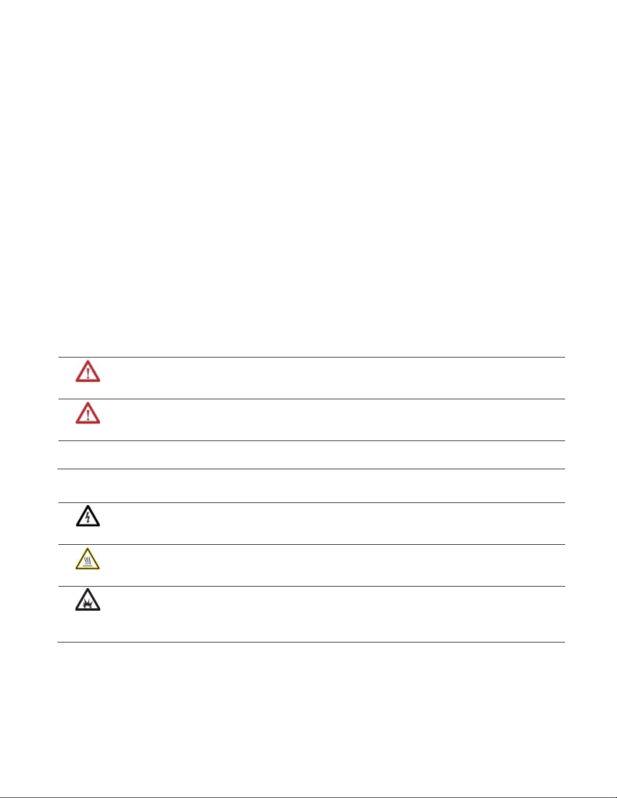
Immediate type motion instructions execute to completion in one scan. If the
controller detects an error during the execution of these instructions, the error
status bit sets and the operation ends.
Examples of immediate type instructions include the:
• Motion Change Dynamics (MCD) instruction
Rockwell Automation Publication MOTION-RM002H-EN-P-February 2018 23
• Motion Group Strobe Position (MGSP) instruction
Immediate instructions work as follows:
1. When the rung that contains the motion instruction becomes true, the
controller:
• Sets the enable (EN) bit.
• Clears the done (DN) bit.
• Clears the error (ER) bit.
2. The controller executes the instruction completely.
Page 24

Preface
Message Type
If the controller: Then:
Does not detect an error when the instruction
executes
Detects an error when the instruction executes
The controller sets the .DN bit.
The controller sets the .ER bit and stores an error
code in the control structure.
3. The next time the rung becomes false after either the .DN or .ER bit sets,
the controller clears the .EN bit.
4. The controller can execute the instruction again when the rung becomes
true.
Message type motion instructions send one or more messages to the servo module.
Instructions
Examples of message type instructions include the:
• Motion Direct Drive On (MDO) instruction
• Motion Redefine Position (MRP) instruction
Message type instruction work as follows:
1. When the rung that contains the motion instruction becomes true, the
controller:
• Sets the enable (EN) bit.
• Clears the done (DN) bit.
• Clears the error (ER) bit.
2. The controller begins to execute the instruction by setting up a message
request to the servo module.
Tip:
The remainder of the instruction executes in parallel to the program scan.
3. The controller checks if the servo module is ready to receive a new message.
24 Rockwell Automation Publication MOTION-RM002H-EN-P-February 2018
4. The controller places the results of the check in the message status word of
the control structure.
5. When the module is ready, the controller constructs and transmits the
message to the module.
Tip:
This process may repeat several times if the instruction requires multiple
messages.
6. The instruction executes.
Page 25
Preface
Process Type
If the controller: Then:
Does not detect an error when the
instruction executes
Detects an error when the instruction
executes
The controller sets the .DN bit.
The controller sets the .ER bit and stores an
error code in the control structure.
7. The next time the rung becomes false after either the .DN or .ER bit sets,
the controller clears the .EN bit.
8. When the rung becomes true, the controller can execute the instruction
again.
Instructions
See also
Motion Direct Drive On (MDO) on page 56
Motion Redefine Position (MRP) on page 149
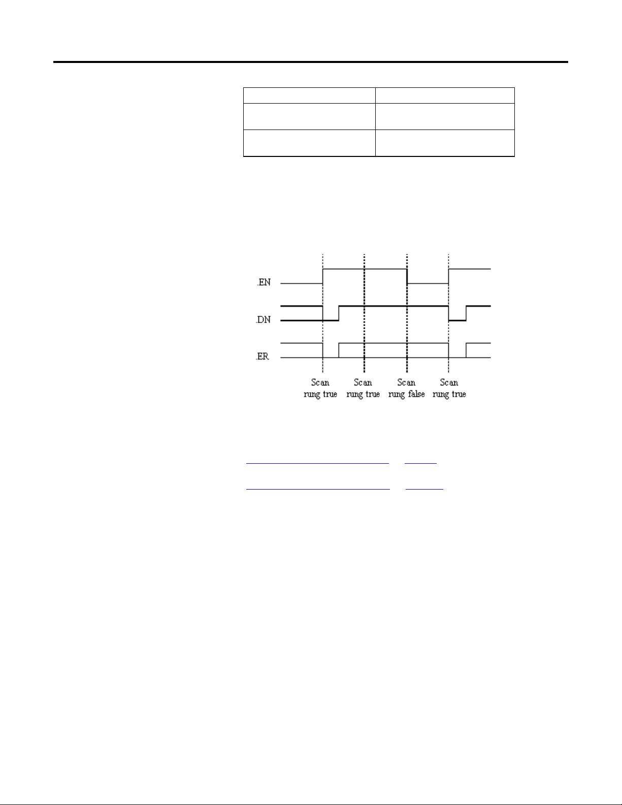
Process type motion instructions initiate motion processes that can take an
indefinite amount of time to complete.
Examples of process type instructions include the:
• Motion Arm Watch Position (MAW) instruction
• Motion Axis Move (MAM) instruction
Process type instructions work as follows:
1. When the rung that contains the motion instruction becomes true, the
controller:
Rockwell Automation Publication MOTION-RM002H-EN-P-February 2018 25
Page 26

Preface
•
• Sets the .ER bit.
•
• Sets the enable (.EN) bit.
• Clears the done (.DN) bit.
• Clears the error (.ER) bit.
• Clears the process complete (.PC) bit.
2. The controller initiates the motion process.
If: Then the controller:
The controller does not detect an error when the
instruction executes
Sets the .DN bit.
• Sets the in process (.IP) bit.
The controller detects an error when the instruction
executes
The controller detects another instance of the motion
instruction
The motion process reaches the point where the
instruction can be executed again
One of the following occurs during the motion
process:
• The motion process completes
• Another instance of the instruction executes
• Another instruction stops the motion process
• A motion fault stops the motion process
3. Once the initiation of the motion process completes, the program scan can
continue.
The remainder of the instruction and the control process continue in parallel with the program scan.
Tip:
4. The next time the rung becomes false after either the .DN bit or the .ER bit
sets, the controller clears the .EN bit.
• Stores an error code in the control structure.
• Does not change the .IP and .PC bits.
Clears the .IP bit for that instance.
Sets the .DN bit.
Tip: For some process type instructions, like MAM, this will occur on the first
scan. For others, like MAH, the .DN bit will not be set until the entire homing
process is complete.
Sets the .DN bit.
• Sets the .PC bit.
• Clears the .IP bit.
26 Rockwell Automation Publication MOTION-RM002H-EN-P-February 2018
Page 27
Preface
Write a Motion
5. When the rung becomes true, the instruction can execute again.
Application Program
To write a motion application program, you can insert motion instructions
directly into the ladder diagram application program. The motion instruction set
consists of five groups of motion instructions:
• Motion state instructions on page 29
• Motion move instructions on page 83
• Motion group instructions on page 211
• Motion event instructions on page 235
• Motion configuration instructions on page 305
These instructions operate on one or more axes. You must identify and configure
axes before you can use them. For more information about configuring axes, see
the ControlLogix Motion Module User Manual, publication 1756-6.5.16.
See also
Understand Motion Status and Configuration Parameters on page 608
Rockwell Automation Publication MOTION-RM002H-EN-P-February 2018 27
Modify Motion Configuration Parameters on page 344
Handle Motion Faults on page 568
Understand a Programming Example on page 243
Page 28

Preface
28 Rockwell Automation Publication MOTION-RM002H-EN-P-February 2018
Page 29

Motion State Instructions
Chapter 1
Motion State Instructions
Motion state control instructions directly control or change the operating states
of an axis. These are the motion state instructions.
Available Instructions
Ladder Diagram and Structured Text
MSO MSF MASD MASR MDO MDF MDS MAFR
Function Block
Not available
Important:
Tags used for the motion control attribute of instructions should only be used once. Re-use of the motion
control tag in other instructions can cause unintended operation. This may result in damage to equipment
or personal injury.
Motion state control instructions directly control or change the operating states of
an axis. The motion state instructions are:
If you want to: Use this instruction:
Enable the servo drive and activate the axis servo loop. MSO
Disable the servo drive and deactivate the axis servo
loop.
Force an axis into the shutdown operating state. Once
the axis is in the shutdown operating state, the
controller will block any instructions that initiate axis
motion.
Change an axis from an existing shutdown operating
state to an axis ready operating state. If all of the axes
of a servo module are removed from the shutdown
state as a result of this instruction, the OK relay
contacts for the module will close.
Enable the servo drive and set the servo output voltage
of an axis.
Deactivate the servo drive and set the servo output
voltage to the output offset voltage.
Activate the drive control loops for the specified axis
and run the motor at the specified speed.
Clear all motion faults for an axis. MAFR
MSF
MASD
MASR
MDO
MDF
MDS
Rockwell Automation Publication MOTION-RM002H-EN-P-February 2018 29
Page 30

Chapter 1
Motion State Instructions
The five operating states of a non-CIP axis are:
Operating State Description
Axis Ready This is the normal power-up state of the axis. In this state:
• The servo module drive enable output is inactive.
• Servo action is disabled.
• No servo faults are present.
Direct Drive Control This operating state allows the servo module DAC to directly
control an external drive. In this state:
• The servo module drive enable output is active.
• Position servo action is disabled.
Servo Control This operating state allows the servo module to perform closed
loop motion. In this state:
• The servo module drive enable output is active.
• Servo action is enabled.
• The axis is forced to maintain the commanded servo position.
Axis Faulted In this operating state, a servo fault is present, and the status of
the drive enable output, the action of the servo, and the
condition of the OK contact depend on the faults and fault
actions that are present.
Shutdown This operating state allows the OK relay contacts to open a set of
contacts in the E- string of the drive power supply. In this state:
• The servo module drive enable output is inactive.
• Servo action is disabled.
• The OK contact is open.
The 16 operating states of a CIP axis are:
As Shown in the Logix Designer
Operating State
Initializing 0 During the Initializing State, the drive first initializes
Programming Application Description
all attributes to their factory default values, that is,
resets all active faults. The drive then waits for the
controller to establish connections to it. Once
connections are established, the controller sets
configuration attributes in the drive to values stored
in the controller. If the drive supports synchronous
operation, the controller then synchronizes with the
drive. Once this process has been completed
successfully, the drive and all its associated axis
instances transition to the Pre-charge state. If a
problem is found during the initializing process, an
Initialization Fault is generated. An Initialization
Fault is an unrecoverable fault. You can only clear the
fault can via a power cycle or a drive reset. If the
connection to the drive closes for any reason during
operation, the drive returns to the Initializing State
30 Rockwell Automation Publication MOTION-RM002H-EN-P-February 2018
Page 31

Motion State Instructions
Chapter 1
Pre-Charge 1 The drive is waiting for the DC Bus to fully charge,
that is, the DC Bus Up status bit is cleared. Once the
DC Bus reaches an operational voltage level, that is,
DC Bus Up status bit is set, the axis transitions to the
Stopped state.
The drive's power structure is always disabled in this
state, that is, the Power Structure Enabled status bit
is cleared. Any attempt to enable the drive via the
Axis Control mechanism while in this state is
reported back to the controller as an error in the
Response Status and the axis remains in the
Pre-charge state.
Stopped 2 In the Stopped state, the drive's inverter power
structure should either be disabled and free of
torque, that is, the Power Structure Enabled status
bit is cleared, or held in a static condition via an
active control loop, that is, Power Structure Enabled
status bit is set. The drive cannot initiate motion in
the Stopped state nor can the drive respond to a
planner generated command reference, that is, the
Tracking Command status bit is cleared.
In general, the axis should be at rest. However, if you
apply an external force or torque to the load, a brake
may be needed to maintain the rest condition. In the
Stopped state, main power is applied to the drive
and the DC Bus are at an operational voltage level. If
there are any Start Inhibited conditions detected
while in this state, the axis transitions to the Start
Inhibited state. If an Enable request or one of the Run
Test service requests is applied to an axis in the
Stopped state, the motion axis transitions to the
Starting state.
Starting 3 When an Enable request is given to an axis in the
Stopped or Stopping state while it is performing a
Flying Start, the axis immediately transitions to the
Starting state. In this state, the drive checks the
following conditions before transitioning to the
Running state.
• Brake Release delay time
• Induction Motor flux level
The drive control and power structures are activated
during the Starting state, that is, the Power Structure
Enabled status bit is set. But the command reference
is set to a local static value and does not track the
command reference derived from the motion
planner, that is, the Tracking Command status bit is
cleared. If all the starting conditions are met, the axis
state transitions to either the Running state or the
Testing state.
Running 4 The drive's power structure is active, that is, the
Power Structure Enabled status bit is set.
Additionally, the selected Control Mode is enabled
and actively tracking command data from the
controller-based or drive-based motion planner
output to affect axis motion, that is, the Tracking
Command status bit is set.
Rockwell Automation Publication MOTION-RM002H-EN-P-February 2018 31
Page 32

Chapter 1
Motion State Instructions
Testing 5 When any one of the Run Test request services is sent
to the motion axis while in the Stopped state, that is,
services that require an active power structure to
execute, the axis immediately transitions to the
Starting state, that is, the Power Structure Enabled
status bit is set. Then once the Starting state
conditions are met, the axis transitions to the Testing
state. Like the Running state, in the Testing state,
the drive's power structure is active.
The motion axis remains in this state for the duration
of the requested test procedure and then returns to
the Stopped state. The motion axis can also exit the
Testing state by either a fault or an explicit Axis
Control request.
Stopping 6 When a Disable request is issued to an axis in the
Running or Testing state, the axis immediately
transitions to the Stopping state. In this state, the
axis is in the process of stopping and no longer tracks
command data from the motion planner, that is, the
Tracking Command status bit is cleared.
Once the selected Stopping Mode procedure has
completed, the axis transitions to the Stopped state.
Aborting 7 When a Major Fault occurs in the drive while the axis
is in either the Running or Testing states, the motion
axis immediately transitions to the Aborting state. In
this state, the axis is in the process of stopping and
no longer tracks command data from the motion
planner, that is, the Tracking Command status bit is
cleared. The Aborting state executes the appropriate
stopping action as specified by the drive. As with the
Stopping state, in the Aborting state the power
structure remains active, that is, the Power Structure
Enabled status bit is set, for as long as the stopping
action takes to complete. Once the stopping
procedure is complete the axis transitions to the
Faulted state.
When faults conditions are detected in the controller
that are not visible to the drive, or when the drive
reports a Minor Fault condition, the controller brings
the axis to a stop, either directly via an Axis Control
state change request or motion planner stop, or
indirectly via a fault handler in the user program. If
the Axis State reported by the driv e is Stopping, the
controller sets the CIP Axis State to Aborting based
on the presence of the fault condition.
32 Rockwell Automation Publication MOTION-RM002H-EN-P-February 2018
Page 33

Motion State Instructions
Chapter 1
Faulted 8 The faulted state is identical to the Stopped state or
the Shutdown state with the exception that there are
one or more faults active. Faults are latched
conditions. Therefore, a Fault Reset is required to
clear the faults and, assuming the original fault
condition has been removed, the axis transitions to
the Axis State of the drive.
There are many different sources of faults:
• CIP Initialization Faults - Faults that occur when
the drive transitions out of the Initializing state.
These faults can apply to a specific axis or the
entire drive.
• CIP Axis Faults - Faults that apply to a specific axis
and are the direct result of Axis Exceptions
configured to generate a Fault response. Axis
exceptions are run-time conditions that are
related to Motor, Inverter, Converter, Bus
Regulator, and Feedback components.
• Safety Fault: Faults that apply to a specific axis
and are generated by a fault condition detected
in the drive’s safety monitor functionality. A
Safety Fault always results in the axis
transitioning to the Stopped state.
• Motion Fault: Faults generally associated with
fault conditions generated by the motion planner
function. These faults can include conditions
related to the input, for example, actual position,
or output, for example, command position,
signals.
• Module Fault: Faults that apply to the entire drive
and affect all axes associated with that drive.
Module faults include all node faults reported by
the drive and also communication fault
conditions detected on the controller side of the
motion connection.
• Group Fault: Faults related to the motion group
object function and affect all axes associated with
the motion group. Group Fault conditions are
detected by controller and are associated with
the time synchronization function common to all
axes in the motion group.
• Configuration Fault: Fault generated anytime
there is an error when sending configuration data
to the drive.
Start Inhibited 9 This state is the same as the Stopped state with the
exception that the axis has one or more 'start inhibit'
conditions that prevent it from successfully
transitioning to the Starting state. Once corrected,
the axis state automatically transitions back to the
Stopped state.
Rockwell Automation Publication MOTION-RM002H-EN-P-February 2018 33
Page 34

Chapter 1
Motion State Instructions
Shutdown 10 When a Shutdown request is issued to the drive or a
Shutdown fault action is executed by the drive, the
targeted axis immediately transitions to the
Shutdown state. The Shutdown state has the same
basic characteristics of the Stopped state except that
it can be configured via the Shutdown Action
attribute to drop the DC Bus power to the drive's
power structure.
Regardless of whether DC Bus power is disconnected,
this state requires an explicit Shutdown Reset
request from the controller to transition to the
Pre-charge state. If the drive is configured to keep DC
Bus power active while in the Shutdown state, then
the motion axis transitions through the Pre-charge
state to the Stopped state.
In the case where a Shutdown fault action is initiated
by the drive in response to an exception condition
that is configured to be a major fault, the drive
executes the Shutdown action. However, the axis
goes to the Faulted state, not the Shutdown state.
Similarly, when the axis is in the Shutdown state and
a major fault condition occurs, the axis transitions to
the Faulted state. A Fault Reset request from the
controller clears the fault and, assuming the original
fault condition has been removed, the axis
transitions to the Shutdown state. A Shutdown Reset
request from the controller, however, both clears the
fault and performs a shutdown reset so, assuming
the original fault condition has been removed, the
axis transitions to the Pre-charge state.
Axis Inhibited 11 If you inhibit the axis, the associated instance in the
CIP Motion connection is eliminated and the axis
state transitions to the Axis Inhibited state. If this is
the only instance supported by the CIP Motion
connection, the connection itself is closed. The Axis
Inhibited state is a controller-only sub state of the
Self-test state
(1)
. The Axis Inhibited condition is
checked during the controller Self-test state as
qualification for transition to the Initializing state. If
currently Axis Inhibited, you must execute an
Un-Inhibit operation to transition to the Initializing
state and restore axis function.
Not Grouped 12 If a CIP Motion axis is created and not associated with
a Motion Group, the axis state is set to the Not
Grouped state. A CIP Motion axis must be assigned to
a Motion Group for the axis to be updated by the
periodic Motion Task and carry out its function. This
condition is checked during the controller Self-test
state as qualification for transition to the Initializing
state. For this reason, the Not Grouped state is
considered a controller-only sub state of the Self-test
state.
34 Rockwell Automation Publication MOTION-RM002H-EN-P-February 2018
Page 35

Motion State Instructions
Chapter 1
Motion Axis Fault Reset (MAFR)
No Device 13 If the CIP Motion axis in the controller is created, but
not currently associated with a drive, the axis state
indicates the No Device state. A CIP Motion axis must
be associated with a physical drive to function. This
condition is checked during the controller Self-test
state as qualification for transition to the Initializing
state. For this reason, the No Device state is
considered a controller-only sub state of the Self Test
state.
(1) The Self-test state is a drive state. This state does not appear in the Logix
Designer programming application as an operating state of a CIP axis. Instead,
self-test is represented as the Initializing state for a CIP axis.
See also
Motion Configuration Instructions on page 305
Motion Move Instructions on page 83
Multi-Axis Coordinated Motion Instructions on page 345
Motion Event Instructions on page 235
Motion Group Instructions on page 211
This information applies to the CompactLogix 5370, ControlLogix 5570,
Compact GuardLogix 5370, GuardLogix 5570, Compact GuardLogix 5380,
CompactLogix 5380, CompactLogix 5480, ControlLogix 5580, and GuardLogix
5580 controllers. Controller differences are noted where applicable.
Use the Motion Axis Fault Reset (MAFR) instruction to clear all motion faults for
an axis. This is the only method for clearing axis motion faults.
Important:
The MAFR instruction removes the fault status, but does not perform any other recovery, such as enabling
servo action. In addition, when the controller removes the fault status, the condition that generated the
fault(s) may still exist. If the condition is not corrected before using the MAFR instruction, the axis immediately
faults again.
Rockwell Automation Publication MOTION-RM002H-EN-P-February 2018 35
Available Languages
Ladder Diagram
Page 36

Chapter 1
Motion State Instructions
Function Block
This instruction is not available in function block.
Structured Text
MAFR(Axis,MotionControl);
Operands
Ladder Diagram and Structured Text
Operand Type
CompactLogix 5380,
CompactLogix 5480,
ControlLogix 5580, Compact
GuardLogix 5380, and
GuardLogix 5580 controllers
Axis AXIS_CIP_DRIVE
AXIS_VIRTUAL
Motion Control MOTION_INSTRUCTION MOTION_INSTRUCTION Tag Structure used to access
Type
CompactLogix 5370, ControlLogix
5570, Compact GuardLogix 5370,
and GuardLogix 5570 controllers
AXIS_CIP_DRIVE
AXIS_VIRTUAL
AXIS_GENERIC
AXIS_GENERIC_DRIVE
AXIS_SERVO
AXIS_SERVO_DRIVE
Format Description
Tag Name of the axis to perform
operation on
instruction status parameters.
See Structured Text Syntax for more information on the syntax of expressions
within structured text.
MOTION_INSTRUCTION Structure
Mnemonic Description
.EN (Enable) Bit 31 It is set when the rung makes a false-to-true transition and remains set until the servo message transaction is completed and the
rung goes false.
.DN (Done) Bit 29 It is set when the axis’ servo action has been successfully disabled and the drive enable and servo active status bits have been
cleared.
.ER (Error) Bit 28 It is set to indicate that the instruction detected an error, such as if you specified an unconfigured axis.
36 Rockwell Automation Publication MOTION-RM002H-EN-P-February 2018
Description
The MAFR instruction directly clears the specified fault status on the specified
axis. It does not correct the condition that caused the error. If the condition is not
corrected prior to executing the MAFR instruction the axis could immediately
fault again giving the appearance that the fault status was not reset.
This instruction is most commonly used as part of a fault handler program, which
provides application specific fault action in response to various potential motion
Page 37

Motion State Instructions
Chapter 1
control faults. Once the appropriate fault action is taken, the MAFR instruction
can be used to clear all active fault status bits.
Important:
The .DN bit is not set immediately. It will be set once the appropriate Motion Module or Drive has
completed its required resets, which could take up to several seconds. Once set the axis is in the
Ready state, but only after the request is completed.
In this transitional instruction, the relay ladder, toggle the Rung-condition-in
from cleared to set each time the instruction should execute.
Affects Math Status Flags
No
Major/Minor Faults
None specific to this instruction. See Common Attributes for operand-related
faults.
Execution
Ladder Diagram
Condition/State Action Taken
Prescan The .EN, .DN, and .ER are cleared to false.
Rung-condition-in is false The .EN bit is cleared to false if the .DN or .ER bit is true.
Rung-condition-in is true The .EN bit is set to true and the instruction executes. If
the EN bit is set to false, then there is no action taken,
Postscan N/A
Rockwell Automation Publication MOTION-RM002H-EN-P-February 2018 37
Structured Text
Condition/State Action Taken
Prescan See Prescan in Ladder Diagram table
Normal execution See Rung-condition-in is false, followed by rung is true in
the Ladder Diagram table.
Postscan See Postscan in Ladder Diagram table.
Error Codes
See Motion Error Codes (.ERR) for Motion Instructions.
Extended Error Codes
Extended Error Codes provide additional instruction specific information for the
Error Codes that are generic to many instructions. See Motion Error Codes (.ERR)
for Motion Instructions.
Page 38

Chapter 1
Motion State Instructions
MAFR Changes to Status Bits
None
Examples
When the input conditions are true, the controller clears all motion faults for
myAxis.
Ladder Diagram
Structured Text
MAFR(myAxis,myMotionControl);
See also
Common Attributes on page 663
Structured Text Syntax on page 635
Motion Error Codes (.ERR) on page 557
MAFR Flow Chart on page 39
38 Rockwell Automation Publication MOTION-RM002H-EN-P-February 2018
Page 39

Motion State Instructions
Chapter 1
MAFR Flow Chart (True)
Rockwell Automation Publication MOTION-RM002H-EN-P-February 2018 39
Page 40

Chapter 1
Motion State Instructions
Motion Axis Shutdown (MASD)
This information applies to the CompactLogix 5370, ControlLogix 5570,
Compact GuardLogix 5370, GuardLogix 5570, Compact GuardLogix 5380,
CompactLogix 5380, CompactLogix 5480, ControlLogix 5580, and GuardLogix
5580 controllers. Controller differences are noted where applicable.
Use the Motion Axis Shutdown (MASD) instruction to force a specified axis into
the Shutdown state. The Shutdown state of an axis is the condition where the
drive output is disabled, servo loop deactivated, and any available or associated OK
solid-state relay contacts open. The axis remains in the Shutdown state until either
an Axis or Group Shutdown Reset is executed.
Available Languages
Ladder Diagram
Function Block
This instruction is not available in function block.
Structured Text
MASD(Axis,MotionControl);
40 Rockwell Automation Publication MOTION-RM002H-EN-P-February 2018
Page 41

Motion State Instructions
Chapter 1
Operands
Ladder Diagram and Structured Text
Operand Type
CompactLogix 5380,
CompactLogix 5480, ControlLogix
5580, Compact GuardLogix 5380,
and GuardLogix 5580 controllers
Axis AXIS_CIP_DRIVE
AXIS_VIRTUAL
Motion Control MOTION_INSTRUCTION
See Structured Text Syntax for more information on the syntax of expressions
within structured text.
MOTION_INSTRUCTION Structure
Mnemonic Description
.EN (Enable) Bit 31 It is set when the rung makes a false-to-true transition and remains set until the servo message
.DN (Done) Bit 29 It is set when the axes have been successfully set to Shutdown state.
.ER (Done) Bit 28 It is set to indicate that the instruction detected an error, such as if you specified an unconfigured
Type
CompactLogix 5370, ControlLogix
5570, Compact GuardLogix 5370,
and GuardLogix 5570 controllers
AXIS_CIP_DRIVE
AXIS_VIRTUAL
AXIS_GENERIC
AXIS_GENERIC_DRIVE
AXIS_SERVO
AXIS_SERVO_DRIVE
transaction is completed and the rung goes false.
axis.
Format Description
Tag Name of the axis to perform
operation on
Tag Structure used to access
instruction status parameters.
Rockwell Automation Publication MOTION-RM002H-EN-P-February 2018 41
Description
The MASD instruction directly and immediately disables drive output, disables
the servo loop, and opens any associated OK contacts. This action places the axis
into the Shutdown state.
Another action initiated by the MASD instruction is the clearing of all motion
processes in progress and the clearing of all the motion status bits. Associated with
this action, the command also clears all motion instruction IP bits that are
currently set for the targeted axis.
The MASD instruction forces the targeted axis into the Shutdown state. One of
the unique characteristics of the Shutdown state is that, when available, the OK
solid state relay contact for the motion module or drive is Open. Where available
this feature can be used to open up the E-Stop string that controls main power to
the drive system. Note that there is typically only one OK contact per motion
module which means that execution of an MASD instruction for either axis
associated with a given module opens the OK contact.
Page 42

Chapter 1
Motion State Instructions
Another characteristic of the Shutdown state is that any instruction that initiates
axis motion is blocked from execution. Attempts to do so result in an execution
error. Only by executing one of the Shutdown Reset instructions can motion be
successfully initiated.
The axis remains in the shutdown state until a Motion Axis Shutdown Reset
(MASR), a Motion Group Shutdown Reset (MGSR), or a Motion Coordinate
Shutdown Reset (MCSR) instruction executes. If the axis is associated with a
Coordinate System, the axis will be reset if the Motion Coordinate Shutdown
Reset (MCSR) instruction executes.
Important:
The instruction execution may take multiple scans to execute because it requires multiple coarse
updates to complete the request. The Done (.DN) bit is not set immediately, but only after the
request is completed.
Additionally, for CIP motion, the MASD instruction supports canceling the
Motion Drive Start (MDS) instruction. This includes clearing the MDS In
Process (.IP) bit, and clearing the DirectVelocityControlStatus and the
DirectTorqueControlStatus bit in the Motion Status attribute.
In this transitional instruction, the relay ladder, toggle the Rung-condition-in
from cleared to set each time the instruction should execute.
Master Driven Speed Control (MDSC) and the MASD Instruction
When the axis is shut down:
• The IP bit of the Master Driven Axis Control (MDAC) instruction is reset
on an axis that is shutdown.
• The AC bit of the MDAC instruction is reset when the axis is stopped as it
is shutdown.
• The MASD instruction clears the pending Master Axis for all future single
motion instructions.
42 Rockwell Automation Publication MOTION-RM002H-EN-P-February 2018
Affects Math Status Flags
No
Major/Minor Faults
None specific to this instruction. See Common Attributes for operand-related
faults.
Page 43

Motion State Instructions
Chapter 1
Execution
Ladder Diagram
Condition/State Action Taken
Prescan The .EN, .DN, and .ER are cleared to false.
Rung-condition-in is false The .EN bit is cleared to false if the .DN or .ER bit is true.
Rung-condition-in is true The .EN bit is set to true and the instruction executes. If
the EN bit is set to false, then there is no action taken.
Postscan N/A
Structured Text
Condition/State Action Taken
Prescan See Prescan in the Ladder Diagram table
Normal execution See Rung-condition-in is false, followed by rung is true in
the Ladder Diagram table.
Postscan See Postscan in the Ladder Diagram table.
Error Codes
See Motion Error Codes (.ERR) for Motion Instructions.
Extended Error Codes
Extended Error Codes provide additional instruction specific information for the
Error Codes that are generic to many instructions. See Motion Error Codes (.ERR)
for Motion Instructions.
MASD Changes to Single Axis Status Bits
Axis Status Bits
Bit Name State Meaning
ServoActionStatus FALSE The axis is in the Servo Off state with the
servo loop inactive.
DriveEnableStatus FALSE The drive enable output is inactive.
ShutdownStatus TRUE The axis is in the shutdown state.
Rockwell Automation Publication MOTION-RM002H-EN-P-February 2018 43
Page 44

Chapter 1
Motion State Instructions
Motion Status Bits
Bit Name State Meaning
AccelStatus FALSE Axis is not Accelerating.
DecelStatus FALSE Axis is not Decelerating.
MoveStatus FALSE Axis is not Moving.
JogStatus FALSE Axis is not Jogging.
GearingStatus FALSE Axis is not Gearing.
HomingStatus FALSE Axis is not Homing.
StoppingStatus FALSE Axis is not Stopping.
PositionCamStatus FALSE Axis is not Position Camming.
TimeCamStatus FALSE Axis is not Time Camming.
PositionCamPendingStatus FALSE Axis does not have a Position Cam
Pending.
TimeCamPendingStatus FALSE Axis does not have a Time Cam Pending.
GearingLockStatus FALSE Axis is not in a Gear Locked condition.
PositionCamLockStatus FALSE Axis is not in a Cam Locked condition.
DirectVelocityControlStatus FALSE Axis is not under Direct Velocity Control.
DirectTorqueControlStatus FALSE Axis is not under Direct Torque Control.
Examples
Ladder Diagram
Structured Text
MASD(myAxis, myMotionControl);
See also
Structured Text Syntax on page 635
MASD Flow Chart (True) on page 45
Motion Error Codes (.ERR) on page 557
Motion State Instructions on page 29
44 Rockwell Automation Publication MOTION-RM002H-EN-P-February 2018
Common Attributes on page 663
Page 45

Motion State Instructions
Chapter 1
MASD Flow Chart (True)
Motion Axis Shutdown Reset
(MASR)
Rockwell Automation Publication MOTION-RM002H-EN-P-February 2018 45
This information applies to the CompactLogix 5370, ControlLogix 5570,
Compact GuardLogix 5370, GuardLogix 5570, Compact GuardLogix 5380,
CompactLogix 5380, CompactLogix 5480, ControlLogix 5580, and GuardLogix
5580 controllers. Controller differences are noted where applicable.
Use the Motion Axis Shutdown (MASR) instruction to transition an axis from an
existing Shutdown state to an Axis Ready state. All faults associated with the
specified axis are automatically cleared. If, as a result of this instruction, all axes of
the associated motion module are no longer in the Shutdown condition, the OK
relay contacts for the module close.
Page 46

Chapter 1
Motion State Instructions
Available Languages
Ladder Diagram
Function Block
This instruction is not available in function block.
Structured Text
MASR(Axis,MotionControl);
Operands
Ladder Diagram and Structured Text
Operand Type
CompactLogix 5380,
CompactLogix 5480,
ControlLogix 5580, Compact
GuardLogix 5380, and
GuardLogix 5580 controllers
Axis AXIS_CIP_DRIVE
AXIS_VIRTUAL
Motion Control MOTION_INSTRUCTION MOTION_INSTRUCTION Tag Structure used to
Type
CompactLogix 5370, ControlLogix
5570, Compact GuardLogix 5370,
and GuardLogix 5570 controllers
AXIS_CIP_DRIVE
AXIS_VIRTUAL
AXIS_GENERIC
AXIS_GENERIC_DRIVE
AXIS_SERVO
AXIS_SERVO_DRIVE
Format Description
Tag Name of the axis to
perform operation on
access instruction
status parameters.
See Structured Text Syntax for more information on the syntax of expressions
within structured text.
MOTION_INSTRUCTION Structure
Mnemonic Description
.EN (Enable) Bit 31 It is set when the rung makes a false-to-true transition and remains set
until the servo message transaction is completed and the rung goes
false.
.DN (Done) Bit 29 It is set when the axes is successfully reset from Shutdown state.
.ER (Done) Bit 28 It is set to indicate that the instruction detected an error, such as if you
specified an unconfigured axis.
46 Rockwell Automation Publication MOTION-RM002H-EN-P-February 2018
Page 47

Motion State Instructions
Chapter 1
Description
The MASR instruction clears all axis faults and takes the specified axis out of the
Shutdown state. If the motion module supports an OK contact, and no other
module axis is in the Shutdown state, the MASR instruction results in closure of
the module’s OK solid-state relay contact. Regardless of the OK contact
condition, execution of the MASR places the axis into the Axis Ready state.
Just as the Motion Axis Shutdown (MASD) instruction forces the targeted axis
into the Shutdown state, the MASR instruction takes the axis out of the
Shutdown state into the Axis Ready state. One of the unique characteristics of the
Shutdown state is that any associated OK solid state relay contact for the motion
module is Open. If, as a result of an MASR instruction there are no axes associated
with a given motion module in the Shutdown state, the OK relay contacts close as
a result of the MASR. This feature can be used to close the E-Stop string that
controls main power to the drive system and, thus, permit the customer to reapply
power to the drive. Note that there is typically only one OK contact per motion
module which means that execution of the MASR instruction may be required for
all axes associated with a given module for the OK contact to close.
The MASR instruction is a procedure type command that is processed from the
Logix controller, through the associated motion module, and to the associated
drives.
Important:
The instruction execution may take multiple scans to execute because it
requires multiple coarse updates to complete the request. The Done (.DN)
bit is not set immediately, but only after the request is completed.
In this transitional instruction, the relay ladder, toggle the rung-condition-in from
cleared to set each time the instruction should execute.
Affects Math Status Flags
No
Major/Minor Faults
None specific to this instruction. See Common Attributes for operand-related
faults.
Rockwell Automation Publication MOTION-RM002H-EN-P-February 2018 47
Page 48

Chapter 1
Motion State Instructions
Execution
Ladder Diagram
Condition/State Action Taken
Prescan The .EN, .DN, and .ER are cleared to false.
Rung-condition-in is false The .EN bit is cleared to false if the .DN or .ER bit is true.
Rung-condition-in is true The .EN bit is set to true and the instruction executes. If the .EN bit is set
to false, no action is taken.
Postscan N/A
Structured Text
Condition/State Action Taken
Prescan See Prescan in the Ladder Diagram table
Normal execution See Rung-condition-in is false, followed by rung is true in the Ladder
Diagram table.
Postscan See Postscan in Ladder Diagram table.
Error Codes
See Motion Error Codes (.ERR) for Motion Instructions.
Extended Error Codes
Extended Error Codes provide additional instruction specific information for the
Error Codes that are generic to many instructions. See Motion Error Codes (.ERR)
for Motion Instructions.
Status Bits
Bit Name State Meaning
ShutdownStatus FALSE The axis is not in the shutdown state.
Examples
When the input conditions are true, the controller resets axis1 from a previous
shutdown operating state into an axis ready operating state.
Ladder Diagram
48 Rockwell Automation Publication MOTION-RM002H-EN-P-February 2018
Page 49

Motion State Instructions
Chapter 1
Structured Text
MASR(myAxis, myMotionControl);
See also
Motion State Instructions on page 29
Common Attributes on page 663
Structured Text Syntax on page 635
Motion Error Codes (.ERR) on page 557
MASR Flow Chart on page 50
Rockwell Automation Publication MOTION-RM002H-EN-P-February 2018 49
Page 50

Chapter 1
Motion State Instructions
MASR Flow Chart (True)
50 Rockwell Automation Publication MOTION-RM002H-EN-P-February 2018
Page 51

Motion State Instructions
Chapter 1
Motion Direct Drive Off (MDF)
This information applies to the CompactLogix 5370, ControlLogix 5570,
Compact GuardLogix 5370, GuardLogix 5570, and ControlLogix 5580
controllers.
Use the Motion Direct Drive Off (MDF) instruction to deactivate the servo drive
and to set the servo output voltage to the output offset voltage. The output offset
voltage is the output voltage that generates zero or minimal drive motion. You can
specify this value during axis configuration.
Available Languages
Ladder Diagram
Function Block
This instruction is not available in function block.
Structured Text
MDF(Axis,MotionControl);
Operands
Ladder Diagram and Structured Text
Operand Type Format Description
Axis AXIS_SERVO Tag Motion Axis of data type
AXIS_SERVO only.
Motion Control MOTION_INSTRUCTION Tag Structure used to access
instruction status parameters.
See Structured Text Syntax for more information on the syntax of expressions
within structured text.
Rockwell Automation Publication MOTION-RM002H-EN-P-February 2018 51
Page 52

Chapter 1
Motion State Instructions
MOTION_INSTRUCTION Structure
Mnemonic Description
.EN (Enable) Bit 31 It is set when the rung makes a false-to-true transition and remains set until
the servo message transaction is completed and the rung goes false.
.DN (Done) Bit 29 It is set when the axis' drive signals have been successfully disabled and the
drive enable status bit is cleared.
.ER (Done) Bit 28 It is set to indicate that the instruction detected an error, such as if you
specified an unconfigured axis.
Description
For motion module’s with an external servo drive interface, the MDF instruction
directly disables the motion module Drive Enable output of the specified physical
axis and also zeroes the modules' servo output to the external drive by applying the
configured Output Offset value.
The MDF instruction is used to stop motion initiated by a preceding Motion
Direct Drive On (MDO) instruction and transition the axis from the Direct
Drive Control state back to the Axis Ready state.
To successfully execute an MDF instruction, the targeted axis must be configured
as a Servo axis. Otherwise, the instruction errors.
Important:
The instruction execution may take multiple scans to execute because it requires multiple
coarse updates to complete the request. The Done (.DN) bit is not set immediately, but only
after the request is completed.
This is a transitional instruction:
• In relay ladder, toggle the EanbleIn false to true each time the instruction
should execute.
• In structured text, condition the instruction so that it only executes on a
transition.
Master Driven Speed Control (MDSC) and the MDF instruction
The MDF instruction goes in conjunction with the MDO on an analog axis. If an
MDF is issued in Master Driven Mode, the system shuts the servo drive off.
The IP bit of the Master Driven Axis Control (MDAC) instruction does not
change on a servo drive that is turned off.
52 Rockwell Automation Publication MOTION-RM002H-EN-P-February 2018
The AC bit of the MDAC instruction resets when the axis stops as it is turned off.
Affects Math Status Flags
No
Page 53

Motion State Instructions
Chapter 1
Major/Minor Faults
None specific to this instruction. See Common Attributes for operand-related
faults.
Execution
Ladder Diagram
Condition/State Action Taken
Prescan The .EN, .DN, and .ER are cleared to false.
Rung-condition-in is false The .EN bit is cleared to false if the .DN or .ER bit is true.
Rung-condition-in is true The .EN bit is set to true and the instruction executes. If
the EN bit is set to false, then there is no action taken,
Postscan N/A
Structured Text
Condition/State Action Taken
Prescan See Prescan in the Ladder Diagram table
Normal execution See Rung-condition-in is false, followed by rung is true in
the Ladder Diagram table.
Postscan See Postscan in the Ladder Diagram table.
Extended Error Codes
Extended Error Codes provide additional instruction specific information for the
Error Codes that are generic to many instructions. See Motion Error Codes (.ERR)
for Motion Instructions.
MDF Changes to Single Axis Status Bits
Axis Status Bits
Bit Name State Meaning
DriveEnableStatus TRUE Axis is in Axis Ready state with the Drive Enable
output now active.
Rockwell Automation Publication MOTION-RM002H-EN-P-February 2018 53
Page 54

Chapter 1
Motion State Instructions
Example
Ladder Diagram
See also
MDF Flow Chart on page 55
Structured Text Syntax on page 635
MDF Flow Chart (True) on page 55
Motion Error Codes (.ERR) on page 557
Common Attributes on page 663
54 Rockwell Automation Publication MOTION-RM002H-EN-P-February 2018
Page 55

Motion State Instructions
Chapter 1
MDF Flow Chart (True)
Rockwell Automation Publication MOTION-RM002H-EN-P-February 2018 55
Page 56

Chapter 1
Motion State Instructions
Motion Direct Drive On (MDO)
This information applies to the CompactLogix 5370, ControlLogix 5570,
Compact GuardLogix 5370, GuardLogix 5570, and ControlLogix 5580
controllers.
Use the Motion Direct Drive On (MDO) instruction in conjunction with motion
modules that support an external analog servo drive interface. This instruction
activates the Drive Enable of the module, enabling the external servo drive, and
also sets the output voltage of the drive of the servo module to the specified voltage
level. The value for Drive Output may be specified in Volts or % of maximum axis’
Output Limit.
Available Languages
Ladder Diagram
Function Block
This instruction is not available in function block.
Structured Text
MDO(Axis,MotionControl, DriveOutput,DriveUnits);
56 Rockwell Automation Publication MOTION-RM002H-EN-P-February 2018
Page 57

Motion State Instructions
Chapter 1
Operands
Ladder Diagram and Structured Text
Operand Type Format Description
Axis AXIS_SERVO Tag Motion Axis of data type AXIS_SERVO
only.
Motion Control MOTION_INSTRUCTION Tag Structure used to access instruction
status parameters.
Drive Output SINT
INT
DINT
REAL
Drive Units Boolean Immediate How do you want to interpret the drive
Immediate
or Tag
Voltage to output in % of servo Output
Limit or in Volts.
output?
0 = Volts
1 = Percent
See Structured Text Syntax for more information on the syntax of expressions
within structured text.
Enter your selection for the operands that require you to select from available
options:
This Operand Has These Options Which You...
Enter As Text Or Enter As a Number
DriveUnits Volts
Percent
0
1
MOTION_INSTRUCTION Structure
Mnemonic Description
.EN (Enable) Bit 31 It is set when the rung makes a false-to-true transition and remains set until the servo
message transaction is completed and the rung goes false.
.DN (Done) Bit 29 It is set when the axis’ drive enable bit is activated and the specified analog output is
successfully applied.
.ER (Done) Bit 28 It is set to indicate that the instruction detected an error, such as if you entered a Drive Output
value that was too large.
Rockwell Automation Publication MOTION-RM002H-EN-P-February 2018 57
Page 58

Chapter 1
Motion State Instructions
Description
For motion modules with an external servo drive interface, the MDO instruction
can be used to directly enable the Drive Enable output of the axis and set the
analog output to a specified level determined by the Drive Output parameter. The
Drive Output parameter can be expressed as a voltage, or as a percent of the
maximum configured output voltage value given by the Output Limit attribute.
The MDO instruction can only be used on a physical axis whose Axis Type is
configured for Servo. The instruction only executes when the axis’ is in the Axis
Ready state (for example, servo action is OFF). The resulting state of the axis is
referred to as the Drive Control state.
The MDO instruction automatically enables the specified axis by activating the
appropriate Drive Enable output before setting the servo module’s analog output
to the specified voltage value. There is, typically, a 500 msec delay between the
activation of the drive enable output and the setting of the analog output to the
specified level to allow the drive’s power structure to stabilize. To minimize drift
during this drive enabling delay, the output voltage to the drive is set to the
Output Offset attribute value (default is zero). Thereafter the output voltage is
given by the specified Drive Output value of the MDO instruction and indicated
by the Servo Output status attribute value.
The 16-bit DAC hardware associated with various Logix servo modules limits the
effective resolution of the Direct Drive Motion Control to 305
V or 0.003%. In
the case of Direct Drive operation, the module’s servo loop is inactive and
bypassed. The Motion Direct Drive On instruction is only affected by the Servo
Output Polarity configuration bit, the Output Offset, and Output Limit
attributes for the axis. In the case where Output Limit configuration value is
reduced below the current output voltage value, the Servo Output value is
automatically clamped to the Output Limit value.
The most common use of this instruction is to provide an independent
programmable analog output as an open loop speed reference for an external drive
or for testing an external servo drive for closed loop operation.
To successfully execute a MDO instruction, the targeted axis must be configured
as a Servo axis and be in the Axis Ready state, with servo action off. If these
conditions are not met the instruction errs.
Important:
The instruction execution may take multiple scans to execute because it requires multiple
coarse updates to complete the request. The Done (.DN) bit is not set immediately, but only
after the request is completed.
This is a transitional instruction:
58 Rockwell Automation Publication MOTION-RM002H-EN-P-February 2018
Page 59

Motion State Instructions
Chapter 1
•
• In relay ladder, toggle the rung-condition-in from false to true each time the
instruction should execute.
• In structured text, condition the instruction so that it only executes on a
transition.
Loss of Feedback When Using an MDO Instruction
If you experience a loss of feedback when issuing an MDO instruction and need to
move the axis with an MDO instruction, follow these steps:
1. Set the Feedback Fault Actions to Status Only.
2. When a feedback fault occurs, issue an MSF instruction to turn the servo
off.
3. Issue an MAFR instruction to clear the feedback fault status.
The MDO instruction executes without another feedback fault shutting down the
system. However, the feedback fault status remains feedback fault condition exists.
Important:
Keep in mind the following when using the previous steps:
• Once feedback has been lost, the reported position may not be valid. To re-establish a valid
position, perform another home operation.
• If you need to issue another MDO instruction, such as to modify the output voltage, when the
first MDO instruction is executing, you must first issue an MSF instruction to stop the servo and
then issue an MAFR instruction to clear the feedback fault.
Affects Math Status Flags
No
Major/Minor Faults
None specific to this instruction. See Common Attributes for operand-related
faults.
Execution
Ladder Diagram
Condition/State Action Taken
Prescan The .EN, .DN, and .ER are cleared to false.
Rung-condition-in is false The .EN bit is cleared to false if the .DN or .ER bit is true.
Rung-condition-in is true The .EN bit is set to true and the instruction executes. If
the EN bit is set to false, there is no action taken,
Postscan N/A
Rockwell Automation Publication MOTION-RM002H-EN-P-February 2018 59
Page 60

Chapter 1
Motion State Instructions
Structured Text
Condition/State Action Taken
Prescan See Prescan in the Ladder Diagram table
Normal execution See Rung-condition-in is false, followed by rung is true in
the Ladder Diagram table.
Postscan See Postscan in the Ladder Diagram table.
Extended Error Codes
Extended Error Codes provide additional instruction specific information for the
Error Codes that are generic to many instructions. See Error Codes (ERR) for
Motion Instructions.
The following Extended Error codes help to pinpoint the problem when the
MDO instruction receives a Servo Message Failure (12) error message.
Extended Error Code (decimal) Associated Error Code (decimal) Meaning
Object Mode conflict (12) SERVO_MESSAGE_FAILURE (12) Axis is shutdown.
Status Bits
MDO Changes to Status Bits
Bit Name State Meaning
DriveEnableStatus TRUE Axis is in Drive Control state with the Drive Enable output
active.
Examples
Example 1
The Drive Output operand is a DINT tag and Drive Units is "Volts"
Ladder Diagram
Structured Text
60 Rockwell Automation Publication MOTION-RM002H-EN-P-February 2018
MDO(myAxis, myMotionControl, myDriveOutput_DINT, volts);
Page 61

Motion State Instructions
Chapter 1
Example 2
The Drive Output operand is a REAL tag and Drive Units is "Percent"
Ladder Diagram
Structured Text
MDO(myAxis, myMotionControl, myDriveOutput_REAL, percent);
See also
MDO Flow Chart (True) on page 62
Structured Text Syntax on page 635
Common Attributes on page 663
Motion Error Codes (.ERR) on page 557
Rockwell Automation Publication MOTION-RM002H-EN-P-February 2018 61
Page 62

Chapter 1
Motion State Instructions
MDO Flow Chart (True)
62 Rockwell Automation Publication MOTION-RM002H-EN-P-February 2018
Page 63

Motion State Instructions
Chapter 1
Motion Drive Start (MDS)
This information applies to the CompactLogix 5370, ControlLogix 5570,
Compact GuardLogix 5370, GuardLogix 5570, Compact GuardLogix 5380,
CompactLogix 5380, CompactLogix 5480, ControlLogix 5580, and GuardLogix
5580 controllers.
Use the Motion Drive Start (MDS) instruction to activate the drive control loops
for the specified axis and run the motor at the specified speed.
Important:
The MDS instruction is validated if the CIP drive device supports the S ramp
attributes, including:
• RampAcceleration
• RampDeceleration
• RampVelocity - Positive
• RampVelocity - Negative
• RampJerk - Control
Available Languages
Ladder Diagram
Function Block
This instruction is not available in function block.
Rockwell Automation Publication MOTION-RM002H-EN-P-February 2018 63
Structured Text
MDS(Axis,MotionControl,Speed,Unitspersec);
Page 64

Chapter 1
Motion State Instructions
Operands
Ladder Diagram and Structured Text
Operand Type Format Description
Axis AXIS_CIP_DRIVE Tag Motion Axis of data type AXIS_CIP_DRIVE
only.
Motion Control MOTION_INSTRUCTION Tag Structure used to control execution of the
motion instruction.
Speed SINT
INT
DINT
REAL
Speed Units SINT
INT
DINT
Immediate or Tag Defines the initial speed for the
DirectVelocityControlStatus Command
attribute.
Immediate Which units do you want to use for the
speed?
0 = % of Maximum
1 = Units per Sec
See Structured Text Syntax for more information on the syntax of expressions
within structured text.
MOTION_INSTRUCTION Structure
Mnemonic Description
.EN (Enable) Bit 31 It is set when the rung makes a false-to-true transition and remains set until the rung
makes a true-to-false transition and drive messaging is complete.
.DN (Done) Bit 29 It is set when the drive has been successfully enabled and remains set until the rung makes
a false-to-true transition.
.ER (Error) Bit 28 It is set when the instruction encounters an error condition. The error condition can be a
direct result of the initial conditions or may result during the instruction’s execution. The
bit remains set until the rung makes a false-to-true transition.
.IP (In process) Bit 26 It is set when the instruction has been successfully initiated and remains set until:
another MDS instruction supersedes the initial instruction
another instruction terminates the initial instruction
a drive fault occurs.
STATE Reflects the state of the instruction.
0 = Sending a request to the drive module to turn the drive on
1 = Waiting for the drive enable and servo action status bits to be set
64 Rockwell Automation Publication MOTION-RM002H-EN-P-February 2018
Page 65

Motion State Instructions
Chapter 1
Description
The MDS instruction:
• Is only valid for the AXIS_CIP_DRIVE axis data type.
• Performs a drive enable if the axis is not in the Running state.
• Applies desired DirectVelocityControlStatus Command attribute and/or
the DirectTorqueControlStatus Command attributes.
• Presents the DirectVelocityControlStatus Command attributes and/or the
DirectTorqueControlStatus Command attributes.
• Is activated on a Rung False-to-True transition.
The MDS instruction is used to activate the direct control of velocity or torque for
a specified axis. The instruction performs an axis enable sequence and then presets
the DirectVelocityControlStatus Command attribute and/or the
DirectTorqueControlStatus Command attribute if the selected drive supports
direct control. The most common usage of the MDS instruction is the flying start
application, where the following attributes directly control the motion dynamics:
• RampAcceleration
• RampDeceleration
• RampVelocity - Positive
• RampVelocity - Negative
• RampJerk - Control
The DirectVelocityControlStatus Command attribute is applied by taking the
value in the speed field in the instruction configuration and copying it into the
DirectVelocityControlStatus Command attribute. The
DirectVelocityControlStatus Command attribute is then scaled and summed
onto the commanded output to the drive device. The
DirectVelocityControlStatus Command attribute value can be modified directly
via the MOV instruction.
The DirectTorqueControlStatus Command attribute is applied by taking the
value in speed field in the instruction configuration and copying it into the
DirectTorqueControlStatus Command attribute. The
DirectTorqueControlStatus Command attribute is then sent directly to the drive
via the placeholder in the CIP Controller to Drive Connection.
Rockwell Automation Publication MOTION-RM002H-EN-P-February 2018 65
A combination of the DirectVelocityControlStatus Command attribute and the
DirectTorqueControlStatus Command attribute can be applied in applications
Page 66

Chapter 1
Motion State Instructions
that require Speed-limited Adjustable Torque (SLAT) modes. SLAT operation
mode provides automatic speed control under certain conditions.
The SLAT Configuration is an enumerated attribute that determines how the
drive controls torque for this axis instance. To support applications that require
SLAT control, the Min/Max torque control enumerations provide a feature to
automatically switch to and from speed control under certain conditions. In either
SLAT mode the drive operates in one of the states described in the following table.
Enumeration Mode Description
0 SLAT disabled SLAT function is disabled. This is the normal Velocity Loop operation.
1 SLAT Min Speed/Torque Drive automatically switches from torque control to speed control if
Velocity Error > SLAT set point and switches back to torque control if
Speed Error < 0.
2 SLAT Max Speed Torque Drive automatically switches from torque control to speed control if
Velocity Error < -SLAT set point and switches back to torque control if
Speed Error > 0.
When you execute the MDS instruction and the drive is configured for velocity
control, the acceleration and deceleration ramp to the specified speed is controlled
by the drives based on the Acceleration Limit and Deceleration Limit attributes.
The Motion Planner takes the value from the Direct Command Velocity attribute
and sums it into the axis output before sending the command to the drive. The
most common use of this instruction is to perform a Drive Start application into a
spinning motor, also known as a Flying Start application.
The axis remains in DirectVelocityControlStatus Command attribute or
DirectTorqueControlStatus Command attribute modes until canceled by one of
the following instructions:
• Motion Axis Stop (MAS)
• Motion Axis Shutdown (MASD)
• Motion Coordinated Shutdown (MCSD)
• Motion Group Shutdown (MGSD)
• Motion Servo Off (MSF)
Depending on how the fault action is configured, an axis fault can also cancel the
MDS instruction.
Execution of the MDS instruction has no effect on motion group or coordinate
system objects. However, the instruction affects axis objects as follows:
When the MDS instruction is initiated without errors, the
DirectVelocityControlStatus bit of the MotionStatus axis attribute is set,
indicating the DirectVelocityControlStatus bit is active on the axis.
66 Rockwell Automation Publication MOTION-RM002H-EN-P-February 2018
Page 67

Motion State Instructions
Chapter 1
The DirectVelocityControlStatus bit remains set until it is made inactive via an
MAS or MASR instruction, or via an axis fault.
Also, when the MDS instruction is initiated without errors, the
DirectTorqueControlStatus bit attribute of the MotionStatus axis attribute is set,
indicating the DirectTorqueControlStatus Command attribute is active on the
axis.
The DirectTorqueControlStatus bit remains set until it is made inactive via an
MAS or MASR instruction, or via an axis fault.
Some fault actions impact the execution of the MDS instruction.
Fault Action Description
Ignore Ignore instructs the device to completely ignore the exception condition. For some exceptions that are
fundamental to the operation of the axis, it may not be possible to Ignore the condition.
Alarm Alarm action instructs the device to set the associated bit in the Axis Alarm word but to otherwise not
affect axis behavior. For some exceptions that are fundamental to the operation of the device, it may
not be possible to select this action or any other action that leaves device operation unaffected.
Fault Status Only Fault Status Only instructs the device to set the associated bit in the Axis Faults word but to otherwise
not affect axis behavior. It is up to the controller to programmatically bring the axis to a stop in this
condition. For some exceptions that are fundamental to the operation of the device, it may not be
possible to select this action or any other action that leaves device operation unaffected.
Stop Planner Stop Motion instructs the device to set the associated bit in the Axis Faults word and instructs the
Motion Planner to perform a controlled stop of all planned motion at the configured Max Decel rate
but otherwise not affect axis behavior. This allows the axis to be subsequently moved via the Motion
Planner without first clearing the fault. For some exceptions that are fundamental to the operation of
the device, it may not be possible to select this action or any other action that leaves device enabled.
Rockwell Automation Publication MOTION-RM002H-EN-P-February 2018 67
Page 68

Chapter 1
Motion State Instructions
Fault Action Description
Stop Drive The Stop Drive action results in the device both setting the associated bit in the Axis Faults word and
bringing the axis to a stop based on the factory set "best" available stopping method. This "best"
stopping method includes both the method of decelerating the motor to a stop and the final state of
the axis given the expected level of control still available. The level of axis control available depends
on the specific exception condition and on the configured control mode.
The available deceleration methods are defined by the Stopping Mode attribute. Standard stopping
modes, listed in decreasing levels of deceleration control, are as follows:
Ramp Decel
Current Limit Decel
Coast
In general, the "best" stopping mode is the most controlled deceleration method still available given
the exception condition.
The final state of the axis in response to the Major Fault exception action can be any one of the
following states that are listed in decreasing levels of control functionality:
Hold (Stopped state with Holding Torque)
Disable (Stopped state with Power Structure Disabled)
Shutdown (DC Bus Power Disabled)
The "best" final state of the axis is the state with the most control functionality still available given the
exception condition. But in all these final states a fault reset must be executed before the axis can be
restored to enabled operation and commanded to move.
If the application requires exception action that is a more severe stopping action than the factory set
"best" method, the controller must initiate that action.
If the application requires exception action that is less severe than the factory set "best" method, the
controller must configure the device axis instance for a Minor Fault exception action and handle the
fault directly. This may put device and motor components at risk and should only be allowed by the
device when there is an opportunity, albeit temporal, for the device to remain operational. This is
important in applications where the value of the product is higher than the value of the motor or
device.
When multiple major faults occur with different stopping actions, the most severe of the associated
stopping actions is applied, i.e. the stopping action that requires the lowest level of control
functionality. This rule also applies to the stopping action associated with the Stopping Mode
associated with a Disable Request.
Shutdown Shutdown forces the axis into the Shutdown state, immediately disabling the drive's power structure.
If Shutdown Action is configured to do so, this action also drops DC Bus power to the drive's power
structure. Therefore, the Shutdown action overrides the drive's best stopping method. An explicit
Shutdown Reset is required to restore the drive to an operational state
68 Rockwell Automation Publication MOTION-RM002H-EN-P-February 2018
This is a transitional instruction:
• In relay ladder, toggle the Rung-condition-in from false to true each time
the instruction should execute.
• In structured text, condition the instruction so that it only executes on a
transition.
Affects Math Status Flags
No
Page 69

Motion State Instructions
Chapter 1
Major/Minor Faults
None specific to this instruction. See Common Attributes for operand-related
faults.
Execution
Ladder Diagram
Condition/State Action Taken
Prescan The .EN, .DN, and .ER are cleared to false.
Rung-condition-in is false The .EN bit is cleared to false if the .DN or .ER bit is true.
Rung-condition-in is true The .EN bit is set to true and the instruction executes. If
the EN bit is set to false, there is no action taken,
Postscan N/A
Structured Text
Condition/State Action Taken
Prescan See Prescan in the Ladder Diagram table
Normal execution See Rung-condition-in is false, followed by rung is true in
the Ladder Diagram table.
Postscan See Postscan in the Ladder Diagram table.
Error Codes
See Motion Error Codes (.ERR) for Motion Instructions.
Extended Error Codes
Extended Error Codes provide additional instruction specific information for the
Error Codes that are generic to many instructions. See Motion Error Codes (.ERR)
for Motion Instructions.
MDS Changes to Status Bits
Axis Status Bits
Bit Name State Meaning
DriveVelocityControlStatus FALSE Axis is not under Direct Velocity
Control.
DirectTorqueControlStatus FALSE Axis is not under Direct Torque
Control.
Rockwell Automation Publication MOTION-RM002H-EN-P-February 2018 69
Page 70

Chapter 1
Motion State Instructions
Examples
Example 1
The Speed operand is a REAL tag and Speed Units is "Units per sec"
Ladder Diagram
Structured Text
MDS(myAxis,myMotionControl,mySpeed_REAL,Unitspersec);
Example 2
The Speed operand is a DINT tag and Speed Units is % of Maximum
Ladder Diagram
Structured Text
MDS(myAxis,myMotionControl,mySpeed_DINT,%ofMaximum);
See also
Motion State Instructions on page 29
Motion Error Codes (.ERR) on page 557
Structured Text Syntax on page 635
70 Rockwell Automation Publication MOTION-RM002H-EN-P-February 2018
Common Attributes on page 663
Page 71

Motion State Instructions
Chapter 1
Motion Servo Off (MSF)
This information applies to the CompactLogix 5370, ControlLogix 5570,
Compact GuardLogix 5370, GuardLogix 5570, Compact GuardLogix 5380,
CompactLogix 5380, CompactLogix 5480, ControlLogix 5580, and GuardLogix
5580 controllers. Controller differences are noted where applicable.
Use the Motion Servo Off (MSF) instruction to deactivate the drive output for
the specified axis and to deactivate the axis' servo loop.
Important: If you execute an MSF instruction while the axis is moving, the axis coasts to an uncontrolled stop.
Available Languages
Ladder Diagram
Function Block
This instruction is not available in function block.
Structured Text
MSF (Axis,MotionControl);
Operands
Ladder Diagram and Structured Text
Operand Type
CompactLogix 5380,
CompactLogix 5480,
ControlLogix 5580, Compact
GuardLogix 5380, and
GuardLogix 5580 controllers
Axis AXIS_CIP_DRIVE AXIS_CIP_DRIVE
Motion Control MOTION_INSTRUCTION MOTION_INSTRUCTION Tag Structure used to access
Type
CompactLogix 5370, ControlLogix
5570, Compact GuardLogix 5370,
and GuardLogix 5570 controllers
AXIS_GENERIC
AXIS_GENERIC_DRIVE
AXIS_SERVO
AXIS_SERVO_DRIVE
Format Description
Tag Name of the axis to
perform operation on
instruction status
parameters.
Rockwell Automation Publication MOTION-RM002H-EN-P-February 2018 71
See Structured Text Syntax for more information on the syntax of expressions
within structured text.
Page 72

Chapter 1
Motion State Instructions
MOTION_INSTRUCTION Structure
Mnemonic Description
.EN (Enable) Bit 31 It is set when the rung makes a false-to-true transition and remains set until the servo message
transaction is completed and the rung goes false.
.DN (Done) Bit 29 It is set when the axis’ servo action has been successfully disabled and the drive enable and servo active
status bits have been cleared.
.ER (Done) Bit 28 It is set to indicate that the instruction detected an error, such as if you specified an unconfigured axis.
Description
The MSF instruction directly and immediately turns off drive output and disables
the servo loop on any physical servo axis. With non-CIP motion, this places the
axis in the Axis Ready state described in Motion State Instructions. With CIP
motion, this places the axis in the Stopped state described in Motion State
Instructions. The MSF instruction also disables any motion planners that may be
active at the time of execution. The MSF instruction requires no parameters –
simply enter or select the desired axis.
If the targeted axis does not appear in the list of available axes, the axis has not
been configured for operation. Use the Tag Editor to create and configure a new
axis.
You can use the MSF instruction to turn servo action off when you must move the
axis by hand. Since the position continues to be tracked even with servo action off.
When the servo loop is turned on again, by the Motion Servo On (MSO)
instruction, the axis is again under closed-loop control, at the new position.
The axis stopping behavior varies depending upon the type of drive. In some cases
the axis coasts to a stop and in other cases the axis decelerates to a stop using the
drive’s available stopping torque.
For non-CIP motion, to execute an MSF instruction successfully, the targeted axis
must be configured as a Servo axis. If this condition is not met, the instruction errs.
If you have an Axis Type of Virtual the instructions errors because with a Virtual
Axis the servo action and drive enable status are forced to always be true. A
Consumed axis data type also errors because only the producing controller can
change the state of a consumed axis.
Important: The instruction execution may take multiple scans to execute because it requires multiple coarse updates
to complete the request. The Done (.DN) bit is not set immediately, but only after the request is
completed.
Additionally, for CIP motion, the MSF instruction supports canceling the Motion
Drive Start (MDS) instruction. This includes clearing the MDS In Process (.IP)
bit, and clearing the DirectVelocityControlStatus bit and the
DirectTorqueControlStatus bit in the Motion Status attribute.
72 Rockwell Automation Publication MOTION-RM002H-EN-P-February 2018
Page 73

Motion State Instructions
Chapter 1
In this transitional instruction, the relay ladder, toggle the Rung-condition-in
from cleared to set each time the instruction should execute.
Master Driven Speed Control (MDSC) and the MSF Instruction
If an MSF is issued in Master Driven Mode, the system shuts the servo off.
The IP bit of the Master Driven Axis Control (MDAC) instruction does not
change on an axis that has its servos turned off.
The AC bit of the MDAC instruction resets when the axis stops as the servos are
turned off.
Affects Math Status Flags
No
Major/Minor Faults
None specific to this instruction. See Common Attributes for operand-related
faults.
Execution
Ladder Diagram
Condition Ladder Diagram Action
Prescan The .EN, .DN, and .ER bits are cleared.
The rung-condition-out is set to false.
Rung-condition-in is false The .EN bit is cleared if the .DN or .ER bit is true.
Rung-condition-in is true The .EN bit is cleared to false if the .DN or .ER bit is true
Postscan The rung-condition-out is set to false.
Structured Text
Condition/State Action Taken
Prescan See Prescan in the Ladder Diagram table
Normal execution See Rung-condition-in is false, followed by rung is true in the Ladder
Diagram table.
Postscan See Postscan in the Ladder Diagram table.
Error Codes
Rockwell Automation Publication MOTION-RM002H-EN-P-February 2018 73
See Motion Error Codes (.ERR) for Motion Instructions.
Page 74

Chapter 1
Motion State Instructions
Extended Error Codes
Extended Error Codes provide additional instruction specific information for the
Error Codes that are generic to many instructions.
MSF Changes to Status Bits
Axis Status Bits
Bit Name State Meaning
ServoActionStatus FALSE Axis is in Servo Off state with the servo loop
inactive.
DriveEnableStatus FALSE Axis Drive Enable output is active.
Motion Status Bits
Bit Name State Meaning
AccelStatus FALSE Axis is not Accelerating.
DecelStatus FALSE Axis is not Decelerating.
MoveStatus FALSE Axis is not Moving.
JogStatus FALSE Axis is not Jogging.
GearingStatus FALSE Axis is not Gearing.
HomingStatus FALSE Axis is not Homing.
StoppingStatus FALSE Axis is not Stopping.
PositionCamStatus FALSE Axis is not Position Camming.
TimeCamStatus FALSE Axis is not Time Camming.
PositionCamPendingStatus FALSE Axis does not have a Position Cam Pending.
TimeCamPendingStatus FALSE Axis does not have a Time Cam Pending.
GearingLockStatus FALSE Axis is not in a Gear Locked condition.
PositionCamLockStatus FALSE Axis is not in a Cam Locked condition.
DirectVelocityControlStatus FALSE Axis is not under Direct Velocity Control.
DirectTorqueControlStatus FALSE Axis is not under Direct Torque Control.
74 Rockwell Automation Publication MOTION-RM002H-EN-P-February 2018
Example
When the input conditions are true, the controller disables the servo drive and the
axis servo loop configured by Axis0.
Ladder Diagram
Page 75

Motion State Instructions
Chapter 1
Structured Text
MSF(myAxis, myMotionControl);
See also
MSF Flow Chart on page 76
Structured Text Syntax on page 635
Motion Error Codes (.ERR) on page 557
Motion State Instructions on page 29
Common Attributes on page 663
Rockwell Automation Publication MOTION-RM002H-EN-P-February 2018 75
Page 76

Chapter 1
Motion State Instructions
MSF Flow Chart (True)
76 Rockwell Automation Publication MOTION-RM002H-EN-P-February 2018
Page 77

Motion State Instructions
Chapter 1
Motion Servo On (MSO)
This information applies to the CompactLogix 5370, ControlLogix 5570,
Compact GuardLogix 5370, GuardLogix 5570, Compact GuardLogix 5380,
CompactLogix 5380, CompactLogix 5480, ControlLogix 5580, and GuardLogix
5580 controllers. Controller differences are noted where applicable.
Use the Motion Servo On (MSO) instruction to activate the drive amplifier for
the specified axis and to activate the axis' servo control loop.
Available Languages
Ladder Diagram
Function Block
This instruction is not available in function block.
Structured Text
MSO(Axis,MotionControl);
Operands
Ladder Diagram and Structured Text
Operand Type
CompactLogix 5380, CompactLogix
5480, ControlLogix 5580, Compact
GuardLogix 5380, and GuardLogix
5580 controllers
Axis AXIS_CIP_DRIVE AXIS_CIP_DRIVE
Motion Control MOTION_INSTRUCTION
Type
CompactLogix 5370,
ControlLogix 5570, Compact
GuardLogix 5370, and
GuardLogix 5570 controllers
AXIS_GENERIC
AXIS_GENERIC_DRIVE
AXIS_SERVO
AXIS_SERVO_DRIVE
Format Description
tag Name of the axis to
perform operation on
tag Structure used to access
instruction status
parameters.
Rockwell Automation Publication MOTION-RM002H-EN-P-February 2018 77
See Structured Text Syntax for more information on the syntax of expressions
within structured text.
Page 78

Chapter 1
Motion State Instructions
Mnemonic Description
.EN (Enable) Bit 31 It is set when the rung makes a false-to-true transition and remains set until the servo message transaction is
completed and the rung goes false.
.DN (Done) Bit 29 It is set when the axis’ servo action has been successfully enabled and the drive enable and servo active status bits
have been set.
.ER (Error) Bit 28 It is set to indicate that the instruction detected an error, such as if you specified an unconfigured axis.
Description
The MSO instruction directly activates the drive and enables the configured servo
loops associated with a physical servo axis. It can be used anywhere in a program,
but should not be used while the axis is moving. If this is attempted, the MSO
instruction generates an Axis in Motion error.
The MSO instruction automatically enables the specified axis by activating the
drive and by activating the associated servo loop. With a non-CIP axis, the
resulting state of the axis is referred to as the Servo Control state. With a CIP axis,
the resulting state of the axis is referred to as the Running state.
The most common use of this instruction is to activate the servo loop for the
specified axis in its current position in preparation for commanding motion.
Important:
The instruction execution may take multiple scans to execute because it
requires multiple coarse updates to complete the request. The Done (.DN)
bit is not set immediately, but only after the request is completed.
In this transitional instruction, the relay ladder, toggle the Rung-condition-in
from cleared to set each time the instruction should execute.
Affects Math Status Flags
No
Major/Minor Faults
None specific to this instruction. See Common Attributes for operand-related
faults.
78 Rockwell Automation Publication MOTION-RM002H-EN-P-February 2018
Page 79

Motion State Instructions
Chapter 1
Execution
Ladder Diagram
Condition/State Action Taken
Prescan The .EN, .DN, and .ER are cleared to false.
Rung-condition-in is false The .EN bit is cleared to false if the .DN or .ER bit is true.
Rung-condition-in is true The .EN bit is set to true and the instruction executes. If
the EN bit is set to false, there is no action taken,
Postscan N/A
Structured Text
Condition/State Action Taken
Prescan See Prescan in the Ladder Diagram table
Normal execution See Rung-condition-in is false, followed by rung is true in
the Ladder Diagram table.
Postscan See Postscan in the Ladder Diagram table.
Error Codes
See Motion Error Codes (.ERR) for Motion Instructions.
Extended Error Codes
Extended Error Codes provide additional instruction specific information for the
Error Codes that are generic to many instructions. See Motion Error Codes (.ERR)
for Motion Instructions. The following Extended Error codes help to pinpoint the
problem when the MSO instruction receives a Servo Message Failure (12) error
message.
Extended Error Code (decimal) Associated Error Code (decimal) Meaning
Object Mode conflict (12) SERVO_MESSAGE_FAILURE (12) Axis is shutdown.
Process terminated on request (15) SERVO_MESSAGE_FAILURE (12) Enable input switch error.
(SERCOS)
Device in wrong state (16) SERVO_MESSAGE_FAILURE (12) Device State not correct
for action. (SERCOS)
MSO Changes to Status Bits
Axis Status Bit
Bit Name State Meaning
ServoActionStatus TRUE Axis is in Servo Control state with the servo loop active.
DriveEnableStatus TRUE The axis drive enable output is active.
Rockwell Automation Publication MOTION-RM002H-EN-P-February 2018 79
Page 80

Chapter 1
Motion State Instructions
Motion Status Bits
None
Examples
Example 1
Ladder Diagram
Structured Text
MSO(myAxis, myMotionControl);
See also
MSO Flow Chart on page 81
Common Attributes on page 663
Structured Text Syntax on page 635
Motion Error Codes (.ERR) on page 557
80 Rockwell Automation Publication MOTION-RM002H-EN-P-February 2018
Page 81

Motion State Instructions
Chapter 1
MSO Flow Chart (True)
Rockwell Automation Publication MOTION-RM002H-EN-P-February 2018 81
Page 82

Page 83

Motion Move Instructions
Chapter 2
Motion Move Instructions
Use the Motion Move instructions to control axis position.
Available Instructions
Ladder Diagram and Structured Text
MAS MAH MAJ MAM MAG MCD MRP MCCP MCSV MAPC MATC MDAC
Function Block
Not available
Important:
Tags used for the motion control attribute of instructions should only be used once. Re-use of the
motion control tag in other instructions can cause unintended operation. This may result in damage
to equipment or personal injury.
The Motion Move instructions are:
If you want to: Use this instruction:
Stop any motion process on an axis. MAS
Home an axis. MAH
Jog an axis. MAJ
Move an axis to a specific position. MAM
Start electronic gearing between two axes. MAG
Change the speed, acceleration, or deceleration of a move or
a jog that is in progress.
Change the command or actual position of an axis. MRP
Calculate a Cam Profile based on an array of cam points. MCCP
Calculate the slave value, slope, and derivative of the slope
for a cam profile and master value.
Start electronic camming between two axes. MAPC
Start electronic camming as a function of time. MATC
Define a Master/Slave relationship between two motion axes
and select which type of move instructions.
MCD
MCSV
MDAC
Rockwell Automation Publication MOTION-RM002H-EN-P-February 2018 83
Page 84

Chapter 2
Motion Move Instructions
Motion Axis Stop (MAS)
See also
Motion Configuration Instructions on page 305
Motion State Instructions on page 29
Multi-Axis Coordinated Motion Instructions on page 345
Motion Event Instructions on page 235
Motion Group Instructions on page 211
This information applies to the CompactLogix 5370, ControlLogix 5570,
Compact GuardLogix 5370, GuardLogix 5570, Compact GuardLogix 5380,
CompactLogix 5380, CompactLogix 5480, ControlLogix 5580, and GuardLogix
5580 controllers. Controller differences are noted where applicable.
Use the Motion Axis Stop (MAS) instruction to stop a specific motion process on
an axis or to stop the axis completely.
Available Languages
Ladder Diagram
84 Rockwell Automation Publication MOTION-RM002H-EN-P-February 2018
Function Block
This instruction is not available for function block.
Structured Text
MAS(Axis,MotionControl,StopType,ChangeDecel,DecelRate,DecelUnits,Chang
eDecelJerk,DecelJerk,Jerk Units)
Page 85

Motion Move Instructions
Chapter 2
Jog = 1
Move = 2
Gear = 3
Home = 4
Tune = 5
Test = 6
Position Cam = 8
Master Offset Move = 9
Direct Control = 10
Operands
Ladder Diagram
Operand Type
CompactLogix 5380,
CompactLogix 5480,
ControlLogix 5580, Compact
GuardLogix 5380, and
GuardLogix 5580 controllers
Axis AXIS_CIP_DRIVE
AXIS_VIRTUAL
AXIS_SERVO
AXIS_SERVO_DRIVE
AXIS_GENERIC_DRIVE
Motion Control MOTION_INSTRUCTION
Stop Type DINT
Type
CompactLogix 5370,
ControlLogix 5570, Compact
GuardLogix 5370, and
GuardLogix 5570 controllers
AXIS_CIP_DRIVE
AXIS_VIRTUAL
AXIS_GENERIC
AXIS_GENERIC_DRIVE
AXIS_SERVO
AXIS_SERVO_DRIVE
Format Description
Tag Name of the axis.
Tag Control tag for the instruction.
Immediate
To Stop Choose this Stop Type
All motion in
process for this axis.
Only a certain type
of motion but leave
other motion
processes running.
All = 0
With this selection, the
instruction stops all motion
on an axis. The stops takes
any coordinated motion on
the axis into account when it
computes the Decel rate and
stops that component of the
coordinated motion. The
other axes components of
the coordinated motion are
unaffected and continue.
If this instruction stops a
Motion Drive Start (MDS)
instruction, the Direct
Control Feature is disabled
and the affected axis is
decelerated to a stop using
the instruction parameters.
Choose the type of motion
that you want to stop:
Rockwell Automation Publication MOTION-RM002H-EN-P-February 2018 85
Time Cam = 7
(1)
The axis could still be
moving when the MAS
instruction is complete.
Page 86

Chapter 2
Motion Move Instructions
Change Decel DINT
Immediate
If you want to Then Choose
Use the Maximum
No = 0
Deceleration rate of
the axis.
Specify the
Yes = 1
deceleration rate.
Decel Rate REAL
Immediate or
Tag
Important: The axis could overshoot its target
position if you reduce the deceleration while a
move is in process.
Deceleration rate of the axis. The instruction uses
this value only if Change Decel is Yes.
Decel Units DINT
Immediate Which units do you want to use for the Decel Rate?
• Units per sec
2
(0)
• % of Maximum (1)
Change Decel
Jerk
DINT
Immediate
If you want to Then Choose
Use the Maximum
No (0)
Deceleration Jerk
rate of the axis.
Program the
Yes (1)
deceleration jerk
rate.
Decel Jerk REAL
Jerk Units DINT
Immediate or
Tag
Immediate
Important: The axis could overshoot its target
position if you reduce the deceleration jerk while a
move is in process.
You must always enter a value for the Decel Jerk
operand. This instruction only uses the value if the
Profile is configured as S-curve.
Decel Jerk is the deceleration jerk rate of the axis.
Use these values to get started.
Decel Jerk = 100 (% of Time)
3
0 = Units per sec
1 = % of Maximum
2 = % of Time (use this value to get started)
86 Rockwell Automation Publication MOTION-RM002H-EN-P-February 2018
(1)
When the MAS instruction is used to with either an All or
DirectVelocityControlStatus Command Stop Type, the selection also clears the
MDS In Process (.IP) bit, and clears the Axis DirectVelocityControlStatus bit in
the Motion Status attribute
Page 87

Motion Move Instructions
Chapter 2
Structured Text
This Operand Has These Options Which You
Enter as Text Or Enter as a Number
Stop Type all
jog
move
gear
home
tune
test
timecam
positioncam
masteroffsetmove
directcontrol
Change Decel no
yes
Decel Units Units per sec2
%ofmaximum
Change Decel Jerk no
yes
Decel Jerk no enumeration
Jerk Units unitspersec3
% of Maximum
% of Time
0
1
2
3
4
5
6
7
8
9
10
0
1
0
1
0
1
You must always enter a value for the Decel Jerk operand. This
instruction only uses the value if the Profile is configured as
S-curve.
Decel Jerk is the deceleration jerk rate of the axis.
Use this value to get started.
Decel Jerk = 100 % of Time (2)
0
1
2
Rockwell Automation Publication MOTION-RM002H-EN-P-February 2018 87
See Structured Text Syntax for more information on the syntax of expressions
within structured text.
Page 88

Chapter 2
Motion Move Instructions
MOTION_INSTRUCTION Structure
To See If Check To See If This
Bit Is Set To
A false-to-true transition caused the
instruction to execute.
The stop was successfully initiated. DN BOOL
An error happened. ER BOOL
The axis is stopping. IP BOOL Any of these actions end the MAS instruction and
The axis is stopped. PC BOOL The PC bit stays set until the rung makes a
EN BOOL The EN bit stays set until the process is complete and
Data Type Notes
the rung goes false.
clear the IP bit:
• The axis is stopped
• Another MAS instruction supersedes this MAS
instruction
• Shutdown command
• Fault Action
false-to-true transition.
Description
Use the MAS instruction when you want a decelerated stop for any controlled
motion in process for the axis. The instruction stops the motion without disabling
the servo loop. A trapezoidal profile is always used for MAS with Stop Type=ALL
for the deceleration regardless of the programmed profile type. Use the instruction
to:
• stop a specific motion process such as jogging, moving, or gearing
• stop the axis completely
• abort a test or tune process initiated by a Motion Run Hookup Diagnostics
(MRHD) instruction or Motion Run Axis Tuning (MRAT) instruction.
If the Stop Type is Then the MAS Instruction Uses This Profile
Jog Same type of profile as the Motion Axis Jog (MAJ) instruction that started the jog.
Move Same type of profile as the Motion Axis Move (MAM) instruction that started the move.
None of the above Trapezoidal.
When MAS ( Stop Type = All ) is used on any axis associated with a coordinate
system and a coordinated motion instruction is running on it, Coordinate system’s
maximum deceleration is used to stop remaining axes. If the coordinate system
contains orientation axes, Coordinate system’s Orientation maximum
deceleration is used for stopping remaining Rx, Ry or Rz axes.
88 Rockwell Automation Publication MOTION-RM002H-EN-P-February 2018
Page 89

Motion Move Instructions
Chapter 2
Example
Suppose you use a Motion Axis Jog (MAJ) instruction with an S-curve profile to
start a jog. Then you use an MAS instruction with a Stop Type of Jog to stop the
jog. In that case, the MAS instruction uses an S-curve profile to stop the jog.
Programming Guidelines
Risk of Velocity and/or End Position Overshoot
If you change move parameters dynamically by any method, that is by changing move dynamics [Motion Change Dynamics
(MCD) instruction or Motion Coordinated Change Dynamics (MCCD)] or by starting a new instruction before the last one has
completed, be aware of the risk of velocity and/or end position overshoot.
A Trapezoidal velocity profile can overshoot if maximum deceleration is decreased while the move is decelerating or is close to
the deceleration point.
An S-curve velocity profile can overshoot if:
• Maximum deceleration is decreased while the move is decelerating or close to the deceleration point; or
• Maximum acceleration jerk is decreased and the axis is accelerating. Keep in mind, however, that jerk can be changed
indirectly if it is specified in % of time.
For more information, see Troubleshooting Axis Motion.
Guidelines Details
In ladder diagram, toggle the rung condition
each time you want to execute the instruction.
In structured text, condition the instruction so
that it only executes on a transition.
This is a transitional instruction:
• In ladder diagram, toggle the rung-condition-in from cleared to set each time you want to
execute the instruction.
In structured text, instructions execute each time they are scanned.
• Condition the instruction so that it only executes on a transition. Use either of these
methods:
• Qualifier of an SFC action
• Structured text construct
For more information, see Structured Text Syntax.
Rockwell Automation Publication MOTION-RM002H-EN-P-February 2018 89
Page 90

Chapter 2
Motion Move Instructions
Choose whether to stop all motion or only a
specific type of motion.
To stop gearing or camming, select the slave
axis.
To stop a Master Offset move, enter the slave
axis but use master units.
Be careful if the instruction changes motion
parameters.
Use the jerk operands for S-curve profiles. Use the jerk operands when
Use % of Time for the easiest programming
and tuning of jerk.
If You Want to Stop Then Choose This Stop Type
All motion in process for this axis. All
Stop only a certain type of motion but
leave other motion processes running.
Example: Suppose your axis is executing both a jog and a move at the same time. And
suppose you want to stop only the jog but leave the move running. In that case, choose a Stop
Type of Jog.
To stop a gearing or position camming process, enter the slave axis to turn off the specific
process and stop the axis. If the master axis is a servo axis, you can stop the master axis which
in turn stops the slave without disabling the gearing or position camming.
Tip: If the Master axis is moved manually while the Master axis was in a disabled state, the
actual position of the slave axis continues to track the Master's position, regardless whether
the MasterReference of the MAPC instruction is set to Actual or Command.
To stop an Absolute or Incremental Master Offset move:
• For Axis, enter the slave axis.
• For Deceleration and Jerk, enter the values and units for the master axis.
When you execute an MAS instruction, the axis uses the new deceleration and jerk rates for
the motion that’s already in process. This can cause an axis to overshoot its speed, overshoot
its end position, or reverse direction. S-curve profiles are more sensitive to parameter
changes.
For more information, see Troubleshoot Axi s Motion.
• The Stop Type is Jog or Move.
• The jog or move uses an S-curve profile.
Under those conditions, the instruction uses an S-curve profile to stop the axis. The instruction
uses a constant deceleration rate for all other types of stops. You must fill in the jerk operands
regardless of the type of stop.
For an easy way to program and tune jerk, enter it as a % of the acceleration or deceleration
time.
For more information, see Tune an S-curve Profile.
The instruction uses a trapezoidal profile and
stops the axis.
The type of motion that you want to stop
The axis could still be moving when the MAS
instruction is complete.
The instruction uses an S-curve profile to stop
the axis only if:
• The Stop Type is Jog or Move, and
• The jog or move used an S-curve profile.
90 Rockwell Automation Publication MOTION-RM002H-EN-P-February 2018
Master Driven Speed Control (MDSC) and the MAS Instruction
If the MAS is executed (goes IP) on the Slave Axis in Master Driven Mode, the
MDSC link is immediately broken. The Slave always stops in Time Driven Mode,
regardless if the active mode is Time Driven or Master Driven.
Page 91

Motion Move Instructions
Chapter 2
Stop Type for MAS
The behavior of the MAS instruction depends on the Stop Type parameter:
• Time CAM, stop type moves, and jogs - When you invoke an MAS with
Stop Type = Time Cam on an axis that is running in Master Driven Mode,
the axis terminates Master Driven Mode, changes to Time Driven Mode,
and stops as specified.
• Master Offset Move - When you invoke an MAS with Stop Type = Master
Offset Move on an axis that is running in Master Driven Mode and
controlling a Position Cam, the offset axis terminates Master Driven Mode,
changes to Time Driven Mode, and stops at the specified deceleration and
deceleration jerk.
• All - When you invoke an MAS with Stop Type = All, the MDSC link is
broken immediately. All motion planners on the specified axis terminate
Master Driven Mode and axes are stopped at the specified deceleration and
deceleration jerk in Time Driven Mode.
If the axes are involved in any coordinated motion (in Master Driven Mode), then
the axes break from the coordinate motion planner and the other axes in the
coordinate system continue. The IP bit is cleared on the Master Driven Axis
Control (MDAC).
Note that MAS ALL on the Master axis does not break the MDSC link. For all
other stop types in which you execute an MAS instruction on an axis that is being
controlled in Master Driven Mode, the motion planner terminates Master Driven
Mode on the requested axis for the requested Stop Type, changes to Time Driven
Mode, and stops at the specified deceleration and deceleration jerk in Time
Driven Mode. Other stop types do not clear the IP bit on the MDAC.
The AC bit of the MDAC instruction resets when the axis is stopped.
MAS All reset the IP bit of the MDAC. Other stop types do not reset the IP bit.
Note that if a stop is issued very close to the programmed endpoint, the actual stop
may be beyond the programmed endpoint, especially if run in Master Driven
Mode.
The status bit CalculatedDataAvailable in an active motion instruction status
word for an MAS instruction resets when an MAS is executed (goes IP). The
CalculatedData is not recomputed.
Affects Math Status Flags
No
Rockwell Automation Publication MOTION-RM002H-EN-P-February 2018 91
Page 92

Chapter 2
Motion Move Instructions
Major/Minor Faults
None specific to this instruction. See Common Attributes for operand related
faults.
Execution
Ladder Diagram
Condition/State Action Taken
Prescan The .EN, .DN, .ER, and .IP bits are cleared to false.
Rung-condition-in is false The .EN bit is cleared to false if the .DN or .ER bit is true.
Rung-condition-in is true The .EN bit is set to true and the instruction executes.
Postscan N/A
Structured Text
Condition/State Action Taken
Prescan See Prescan in Ladder Diagram table
Normal execution See Rung-condition-in is false, followed by rung is true in the Ladder
Diagram table.
Postscan See Postscan in Ladder Diagram table.
Error Codes
See Motion Error Codes (.ERR).
Extended Error Codes
Use Extended Error Codes (.EXERR) for more instructions about an error. See
Motion Error Codes (.ERR).
If ERR is And EXERR is Then
13 Varies An operand is outside its range. The EXERR is the number of the operand that is out of
Cause Corrective Action
range. The first operand is 0.
For example, if EXERR = 4, then check the Decel Rate.
EXERR MAS Operand
0 Axis
1 Motion Control
2 Stop Type
3 Change Decel
4 Decel Rate
92 Rockwell Automation Publication MOTION-RM002H-EN-P-February 2018
Page 93

Motion Move Instructions
Chapter 2
Motion Axis Home (MAH)
MAS Changes to Single Axis Status Bits
Motion Status Bits
If the Stop Type Is Then
NOT All The instruction clears the Motion Status bit for the motion process that you stopped.
All The instruction clears all Motion Status bits.
Bit Name State Meaning
MoveStatus FALSE Axis is not Moving.
JogStatus FALSE Axis is not Jogging.
GearingStatus FALSE Axis is not Gearing.
HomingStatus FALSE Axis is not Homing.
StoppingStatus TRUE Axis is Stopping.
PositionCamStatus FALSE Axis is not Position Camming.
TimeCamStatus FALSE Axis is not Time Camming.
PositionCamPendingStatus FALSE Axis does not have a Position Cam Pending.
TimeCamPendingStatus FALSE Axis does not have a Time Cam Pending.
GearingLockStatus FALSE Axis is not in a Gear Locked condition.
PositionCamLockStatus FALSE Axis is not in a Cam Locked condition.
DirectVelocityControlStatus FALSE Axis is not under Direct Velocity Control.
DirectTorqueControlStatus FALSE Axis is not under Direct Torque Control.
See also
Troubleshoot Axis Motion on page 608
Structured Text Syntax on page 635
Motion Error Codes (.ERR) on page 557
Motion Move Instructions on page 83
Common Attributes on page 663
This information applies to the CompactLogix 5370, ControlLogix 5570,
Compact GuardLogix 5370, GuardLogix 5570, Compact GuardLogix 5380,
CompactLogix 5380, CompactLogix 5480, ControlLogix 5580, and GuardLogix
5580 controllers. Controller differences are noted where applicable.
Use the Motion Axis Home (MAH) instruction to home an axis. Two different
homing modes can be selected during axis configuration: Active or Passive. If an
Active homing sequence is selected, the axis executes the configured Home
Sequence Type and establishes an absolute axis position. If Passive homing is
selected, however, no specific homing sequence is executed and the axis is left
waiting for the next marker pulse to establish the home position.
Rockwell Automation Publication MOTION-RM002H-EN-P-February 2018 93
Page 94

Chapter 2
Motion Move Instructions
Available Languages
Ladder Diagram
Function Block
This instruction is not available in function block
Structured Text
MAH(Axis,MotionControl);
Operands
Ladder Diagram and Structured Text
Operand Type
CompactLogix 5380,
CompactLogix 5480,
ControlLogix 5580,
Compact GuardLogix
5380, and GuardLogix
5580 controllers
Axis AXIS_CIP_DRIVE
AXIS_VIRTUAL
Motion Control
See Structured Text Syntax for more information on the syntax of expressions
within structured text.
Type
CompactLogix 5370, ControlLogix
5570, Compact GuardLogix 5370, and
GuardLogix 5570 controllers
AXIS_CIP_DRIVE
AXIS_VIRTUAL
AXIS_GENERIC
AXIS_GENERIC_DRIVE
AXIS_SERVO
AXIS_SERVO_DRIVE
MOTION_INSTRUCTION Tag Structure used to access
Format Description
Tag Name of the axis to
perform operation on.
instruction status
parameters.
94 Rockwell Automation Publication MOTION-RM002H-EN-P-February 2018
Page 95

Motion Move Instructions
Chapter 2
MOTION_INSTRUCTION Structure
Mnemonic Description
.EN (Enable) Bit 31 It is set when the rung makes a false-to-true transition and remains set until the servo
message transaction is completed and the rung goes false.
.DN (Done) Bit 29 It is set when axis home has been successfully completed or is aborted.
.ER (Error) Bit 28 It is set to indicate that the instruction detected an error, such as if you specified an
unconfigured axis.
.IP (In Process) Bit 27 It is set on positive rung transition and cleared after the Motion Home Axis is complete, or
terminated by a stop command, shutdown, or a servo fault.
.PC (Process Complete) Bit 26 It is set when axis home is successfully completed.
Description
The MAH instruction is used to calibrate the absolute position of the specified
axis. For axes that are configured as type Servo, the axis can be homed using Active,
Passive, or Absolute Homing Mode configuration. For Feedback Only axes, only
Passive and Absolute homing modes are available. Absolute Homing Mode
requires the axis to be equipped with an absolute feedback device.
Important: Absolute Homing mode is not available with a CIP axis. However, any successful Home sequence
establishes an absolute position.
For CIP axes only, software overtravels are disabled if the Home status bit
transitions to the FALSE state.
The MAH instructions sets the HomedStatus bit upon successful completion of
the configured homing sequence. This bit indicates that an absolute machine
reference position has been established. When this bit is set, operations that
require a machine reference, such as Software Overtravel checking can be
meaningfully enabled.
For non-CIP Drive axis data types, the HomedStatus bit is cleared under the
following conditions:
• Download
• Control power cycle
• Reconnection to Motion Module
• Feedback Loss Fault
• Shutdown
Rockwell Automation Publication MOTION-RM002H-EN-P-February 2018 95
Page 96

Chapter 2
Motion Move Instructions
Active Homing
When the axis Homing Mode is configured as Active, the physical axis is first
activated for servo operation. As part of this process, all other motion in process is
canceled and appropriate status bits are cleared. The axis is then homed using the
configured Home Sequence, which may be Immediate, Switch, Marker, or
Switch-Marker. The latter three Home Sequences result in the axis being jogged in
the configured Home Direction and then, after the position is re-defined based on
detection of the home event, the axis is automatically moved to the configured
Home Position.
Passive Homing
When the axis Homing Mode is configured as Passive, the MAH instruction
re-defines the actual position of a physical axis on the next occurrence of the
encoder marker. Passive homing is most commonly used to calibrate Feedback
Only axes to their markers, but can also be used on Servo axes. Passive homing is
identical to active homing to an encoder marker, except that the motion controller
does not command any axis motion.
After initiating passive homing, the axis must be moved past the encoder marker
for the homing sequence to complete properly. For closed-loop Servo axes, this
may be accomplished with a MAM or MAJ instruction. For physical Feedback
Only axes, motion cannot be commanded directly by the motion controller, and
must be accomplished via other means.
Absolute Homing
If the motion axis hardware supports an absolute feedback device, Absolute
Homing Mode may be used. The only valid Home Sequence for an absolute
Homing Mode is "immediate". In this case, the absolute homing process
establishes the true absolute position of the axis by applying the configured Home
Position to the reported position of the absolute feedback device. Prior to
execution of the absolute homing process via the MAH instruction, the axis must
be in the Axis Ready state with the servo loop disabled.
To successfully execute a MAH instruction on an axis configured for Active
homing mode, the targeted axis must be configured as a Servo Axis Type. To
successfully execute an MAH instruction, the targeted axis must be configured as
either a Servo or Feedback Only axis. If any of these conditions are not met, the
instruction errors.
96 Rockwell Automation Publication MOTION-RM002H-EN-P-February 2018
Important: The instruction execution may take multiple scans to execute because it requires multiple coarse updates to
complete the request. The Done (.DN) bit is not set immediately, but only after the request is completed.
In this transitional instruction, the relay ladder, toggle the Rung-condition-in
from cleared to set each time the instruction should execute.
Page 97

Motion Move Instructions
Chapter 2
Master Driven Speed Control (MDSC) and the MAH Instruction
When either an MDAC or MDCC is active:
• If a MAH is executed (goes IP) on a Master axis and the Master axis is not
moving, the MDAC or MDCC remains active. If MDAC or MDCC is
active while the MAH is executed (goes IP), the slave moves.
• If an MAH is executed (goes IP) on a Master axis and the Master axis is
moving, the MAH will error. The MDAC or MDCC state remains
unchanged.
• If an MAH is executed (goes IP) on a Slave axis and the Slave axis is not
moving, the MDAC or MDCC is canceled.
• If an MAH is executed (goes IP) on a Slave axis while it is moving in MDSC
Driven or Time Driven modes, the MAH will error. The state of MDAC or
MDCC remains unchanged.
Affects Math Status Flags
No
Major/Minor Faults
None specific to this instruction. See Common Attributes for operand-related
faults.
Execution
Ladder Diagram
Condition/State Action Taken
Prescan The .EN, .DN, .ER, and .IP bits are cleared to false.
Rung-condition-in is false The .EN bit is cleared to false if the .DN or .ER bit is true.
Rung-condition-in is true The .EN bit is set to true and the instruction executes.
Postscan N/A
Structured Text
Condition/State Action Taken
Prescan See Prescan in Ladder Diagram table
Normal execution See Rung-condition-in is false, followed by rung is true in
the Ladder Diagram table.
Postscan See Postscan in Ladder Diagram table.
Rockwell Automation Publication MOTION-RM002H-EN-P-February 2018 97
Page 98

Chapter 2
Motion Move Instructions
Error Codes
See Motion Error Codes (.ERR) for Motion Instructions.
Extended Error Codes
Extended Error Codes provide additional instruction specific information for the
Error Codes that are generic to many instructions. See Motion Error Codes
(.ERR) for Motion Instructions.
The following Extended Error codes help to pinpoint the problem when the
MAH instruction receives a Servo Message Failure (12) error message or Illegal
Homing Configuration (41).
Associated Error Code (decimal) Extended Error Code (decimal) Meaning
SERVO_MESSAGE_FAILURE (12) Process terminated on request (1) Home execution followed by an
instruction to shutdown/disable drive,
or a motion stop instruction or a
Processor change requests a cancel of
Home.
SERVO_MESSAGE_FAILURE (12) No Resources (2) Not enough memory resources to
complete request. (SERCOS)
SERVO_MESSAGE_FAILURE (12) Object Mode conflict (12) Axis is in shutdown.
SERVO_MESSAGE_FAILURE (12) Permission denied (15) Enable input switch error. (SERCOS)
SERVO_MESSAGE_FAILURE (12) Device in wrong state (16) Redefine Position, Home, and
Registration 2 are mutually exclusive
(SERCOS), device state not correct for
action. (SERCOS)
ILLEGAL_HOMING_CONFIG (41) Home sequence (4) The Home Sequence is incompatible
with the Home Mode.
ILLEGAL_HOMING_CONFIG (41) Home speed of zero (6) Home speed cannot be zero.
ILLEGAL_HOMING_CONFIG (41) Home return speed of zero (7) The Home Return Speed cannot be zero.
98 Rockwell Automation Publication MOTION-RM002H-EN-P-February 2018
For the Error Code 54 – Maximum Deceleration Value is Zero, if the Extended
Error returns a positive number (0-n) it is referring to the offending axis in the
coordinate system. Go to the Coordinate System Properties General Tab and look
under the Brackets ([ ])column of the Axis Grid to determine which axis has a
Maximum Deceleration value of 0. Click on the ellipsis button next to the
offending axis to access the Axis Properties screen. Go to the Dynamics tab and
make the appropriate change to the Maximum Deceleration Value. If the
Extended Error number is -1, this means the Coordinate System has a Maximum
Deceleration Value of 0. Go to the Coordinate System Properties Dynamics Tab
to correct the Maximum Deceleration value.
Page 99

Motion Move Instructions
Chapter 2
Status Bits
MAH Changes to Single Axis Status Bits
Bit Name State Meaning
HomingStatus TRUE Axis is Homing.
JogStatus FALSE Axis is no longer Jogging.*
MoveStatus FALSE Axis is no longer Moving.*
GearingStatus FALSE Axis is no longer Gearing.
StoppingStatus FALSE Axis is no loner Stopping.
*During portions of the active homing sequence these bits may be set and cleared.
The MAH instruction uses the Move and Jog motion profile generators to move
the axis during the homing sequence. This also means that any disruption in the
Move or Jog motion profiles due to other motion instructions can affect the
successful completion of the MAH initiated homing sequence.
If in Passive homing mode, the MAH instruction simply sets the Homing Status
bit.
See also
Structured Text Syntax on page 635
MAH Flow Chart (True) on page 100
Motion Error Codes (.ERR) on page 557
Common Attributes on page 663
Rockwell Automation Publication MOTION-RM002H-EN-P-February 2018 99
Page 100

Chapter 2
Motion Move Instructions
MAH Flow Chart (True)
100 Rockwell Automation Publication MOTION-RM002H-EN-P-February 2018
 Loading...