

Allen-Bradley 1756-L55M13, 1756-L55M22, 1756-L55M12, 1756-L55M14, 1756-L55M16 User Manual
...Page 1

ControlLogix
Controllers
1756-L55M12, 1756-L55M13,
1756-L55M14, 1756-L55M16,
1756-L55M22, 1756-L55M23,
1756-L55M24, 1756-L61, 1756-L62,
1756-L63, 1756-L64,
1756-L60M03SE
Firmware Revision 16
User Manual
Page 2
Important User Information
Solid state equipment has operational characteristics differing from those of
electromechanical equipment. Safety Guidelines for the Application,
Installation and Maintenance of Solid State Controls (Publication SGI-1.1
available from your local Rockwell Automation sales office or online at
http://literature.rockwellautomation.com) describes some important
differences between solid state equipment and hard-wired electromechanical
devices. Because of this difference, and also because of the wide variety of
uses for solid state equipment, all persons responsible for applying this
equipment must satisfy themselves that each intended application of this
equipment is acceptable.
In no event will Rockwell Automation, Inc. be responsible or liable for
indirect or consequential damages resulting from the use or application of
this equipment.
The examples and diagrams in this manual are included solely for illustrative
purposes. Because of the many variables and requirements associated with
any particular installation, Rockwell Automation, Inc. cannot assume
responsibility or liability for actual use based on the examples and diagrams.
No patent liability is assumed by Rockwell Automation, Inc. with respect to
use of information, circuits, equipment, or software described in this manual.
Reproduction of the contents of this manual, in whole or in part, without
written permission of Rockwell Automation, Inc. is prohibited.
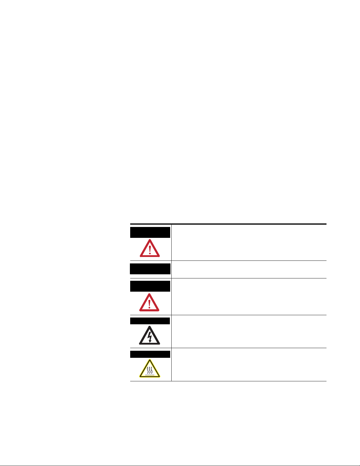
Throughout this manual we use notes to make you aware of safety
considerations.
WARNING
IMPORTANT
ATTENTION
SHOCK HAZARD
BURN HAZARD
Identifies information about practices or circumstances that can cause
an explosion in a hazardous environment, which may lead to personal
injury or death, property damage, or economic loss.
Identifies information that is critical for successful application and
understanding of the product.
Identifies information about practices or circumstances that can lead
to personal injury or death, property damage, or economic loss.
Attentions help you identify a hazard, avoid a hazard, and recognize
the consequence
Labels may be on or inside the equipment, for example, a drive or
motor, to alert people that dangerous voltage may be present.
Labels may be on or inside the equipment, for example, a drive or
motor, to alert people that surfaces may reach dangerous
temperatures.
Page 3

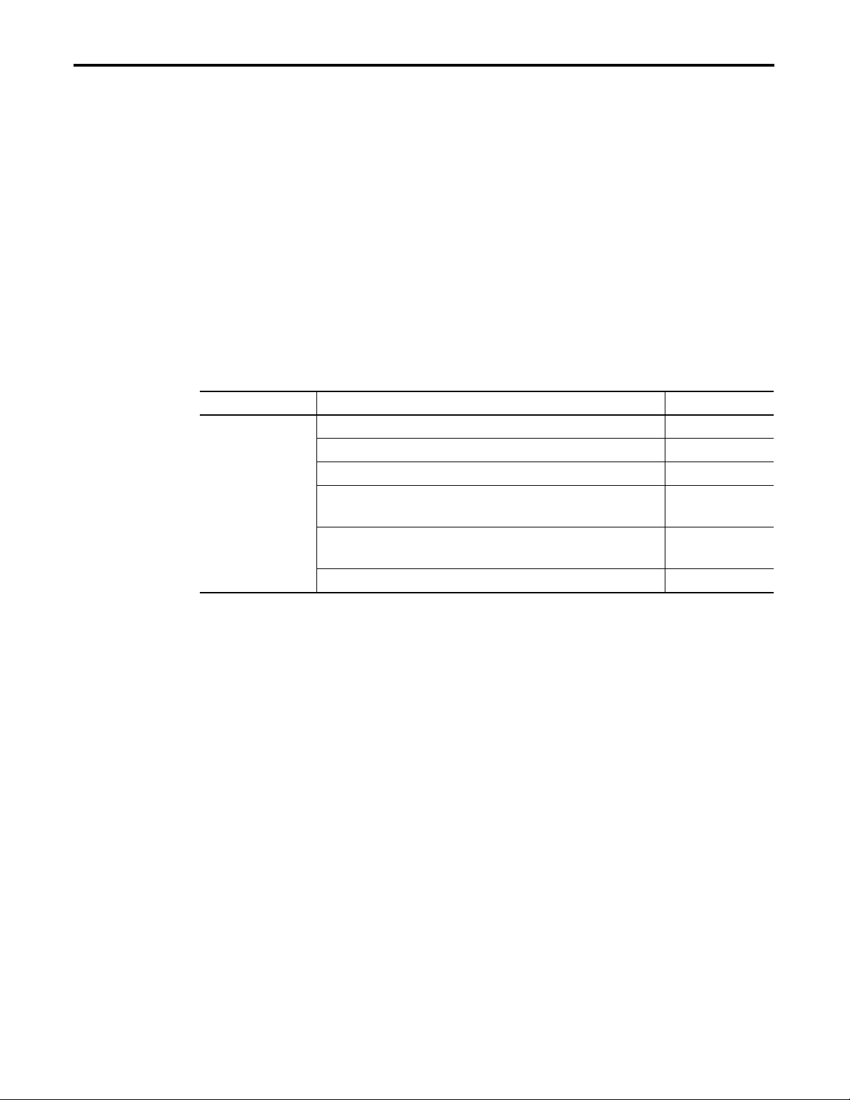
Summary of Changes
Introduction
Updated Information
Topic Page
1756-L64 ControlLogix Controller Throughout manual
Add-On Instructions 73
Select a System Overhead Percentage 79
Add Your Axes 100
Obtain Axis Information 108
The release of this document contains new and updated information.
To find new and updated information, look for change bars, as shown
next to this paragraph.
The document contains these changes.
3 Publication 1756-UM001G-EN-P - January 2007
Page 4

Summary of Changes 4
Notes:
Publication 1756-UM001G-EN-P - January 2007
Page 5

ControlLogix System Overview
Directly Connect to the Controller
via the Serial Port
Communicate over Networks
Table of Contents
Preface
About this Publication . . . . . . . . . . . . . . . . . . . . . . . . . . . . . . 9
Who Should Use This Publication . . . . . . . . . . . . . . . . . . . . . 9
Additional Resources. . . . . . . . . . . . . . . . . . . . . . . . . . . . . . . 9
Chapter 1
Introduction . . . . . . . . . . . . . . . . . . . . . . . . . . . . . . . . . . . . 11
Design . . . . . . . . . . . . . . . . . . . . . . . . . . . . . . . . . . . . . . . . 13
Install Hardware . . . . . . . . . . . . . . . . . . . . . . . . . . . . . . . . . 13
Chapter 2
Introduction . . . . . . . . . . . . . . . . . . . . . . . . . . . . . . . . . . . . 15
Connect the Controller to via the Serial Port. . . . . . . . . . . . . 15
Configure the Serial Driver . . . . . . . . . . . . . . . . . . . . . . . . . 17
Select the Controller Path . . . . . . . . . . . . . . . . . . . . . . . . . . 19
Chapter 3
Introduction . . . . . . . . . . . . . . . . . . . . . . . . . . . . . . . . . . . . 21
EtherNet/IP Network Communication . . . . . . . . . . . . . . . . . 22
Connections Over an EtherNet/IP Network . . . . . . . . . . . 24
Additional Resources . . . . . . . . . . . . . . . . . . . . . . . . . . . 25
ControlNet Network Communication . . . . . . . . . . . . . . . . . . 25
Connections Over a ControlNet Network . . . . . . . . . . . . 27
Additional Resources . . . . . . . . . . . . . . . . . . . . . . . . . . . 28
DeviceNet Network Communication . . . . . . . . . . . . . . . . . . 28
Connections over DeviceNet . . . . . . . . . . . . . . . . . . . . . 30
Additional Resources . . . . . . . . . . . . . . . . . . . . . . . . . . . 30
Serial Network Communication . . . . . . . . . . . . . . . . . . . . . . 31
Communicate with DF1 Devices. . . . . . . . . . . . . . . . . . . 32
Communicate with ASCII Devices. . . . . . . . . . . . . . . . . . 34
Modbus Support . . . . . . . . . . . . . . . . . . . . . . . . . . . . . . 37
DH-485 Network Communication . . . . . . . . . . . . . . . . . . . . 37
Additional Resources . . . . . . . . . . . . . . . . . . . . . . . . . . . 41
DH+ Network Communication. . . . . . . . . . . . . . . . . . . . . . . 41
Communicate over a DH+ Network . . . . . . . . . . . . . . . . 42
Universal Remote I/O Communication . . . . . . . . . . . . . . . . . 43
Communicate Over a Universal Remote I/O Network . . . 44
Foundation Fieldbus . . . . . . . . . . . . . . . . . . . . . . . . . . . . . . 45
Additional Resources . . . . . . . . . . . . . . . . . . . . . . . . . . . 45
HART (Highway Addressable Remote Transducer) Protocol . 46
Additional Resources . . . . . . . . . . . . . . . . . . . . . . . . . . . 46
Chapter 4
Manage Controller
Communication
5 Publication 1756-UM001G-EN-P - January 2007
Introduction . . . . . . . . . . . . . . . . . . . . . . . . . . . . . . . . . . . . 47
Connection Overview . . . . . . . . . . . . . . . . . . . . . . . . . . . . . 47
Additional Resources . . . . . . . . . . . . . . . . . . . . . . . . . . . 47
Page 6

6 Table of Contents
Place, Configure, and Monitor I/O
Modules
Produce and Consume (Interlock) Data . . . . . . . . . . . . . . . . 48
Additional Resources . . . . . . . . . . . . . . . . . . . . . . . . . . . 48
Send and Receive Messages. . . . . . . . . . . . . . . . . . . . . . . . . 49
Determine Whether to Cache Message Connections . . . . 49
Calculate Connection Use . . . . . . . . . . . . . . . . . . . . . . . . . . 50
Connections Example. . . . . . . . . . . . . . . . . . . . . . . . . . . 52
Chapter 5
Introduction . . . . . . . . . . . . . . . . . . . . . . . . . . . . . . . . . . . . 53
Select I/O Modules . . . . . . . . . . . . . . . . . . . . . . . . . . . . . . . 53
Additional Resources . . . . . . . . . . . . . . . . . . . . . . . . . . . 53
Place Local I/O Modules . . . . . . . . . . . . . . . . . . . . . . . . . . . 54
Additional Resources . . . . . . . . . . . . . . . . . . . . . . . . . . . 54
Configure I/O . . . . . . . . . . . . . . . . . . . . . . . . . . . . . . . . . . . 55
I/O Connections . . . . . . . . . . . . . . . . . . . . . . . . . . . . . . 56
Additional Resources . . . . . . . . . . . . . . . . . . . . . . . . . . . 56
Configure Distributed I/O on an EtherNet/IP Network . . . . . 57
Additional Resources . . . . . . . . . . . . . . . . . . . . . . . . . . . 57
Configure Distributed I/O on a ControlNet Network . . . . . . . 58
Additional Resources . . . . . . . . . . . . . . . . . . . . . . . . . . . 58
Configure Distributed I/O on a DeviceNet Network . . . . . . . 59
Additional Resources . . . . . . . . . . . . . . . . . . . . . . . . . . . 59
Address I/O Data . . . . . . . . . . . . . . . . . . . . . . . . . . . . . . . . 60
Add 1756 I/O at Runtime. . . . . . . . . . . . . . . . . . . . . . . . . . . 61
ControlNet I/O Considerations . . . . . . . . . . . . . . . . . . . . 61
EtherNet/IP I/O Considerations . . . . . . . . . . . . . . . . . . . 62
Determine When Data Is Updated . . . . . . . . . . . . . . . . . . . . 63
Reconfigure an I/O Module . . . . . . . . . . . . . . . . . . . . . . . . . 64
Reconfigure a Module via RSLogix 5000
Programming Software . . . . . . . . . . . . . . . . . . . . . . . . . . 64
Reconfigure an I/O Module via a MSG Instruction. . . . . . 65
Develop Applications
Publication 1756-UM001G-EN-P - January 2007
Chapter 6
Introduction . . . . . . . . . . . . . . . . . . . . . . . . . . . . . . . . . . . . 67
Additional Resources . . . . . . . . . . . . . . . . . . . . . . . . . . . 67
Manage Tasks . . . . . . . . . . . . . . . . . . . . . . . . . . . . . . . . . . . 67
DevelopPrograms . . . . . . . . . . . . . . . . . . . . . . . . . . . . . . . . 68
Define Tasks . . . . . . . . . . . . . . . . . . . . . . . . . . . . . . . . . 69
Define Programs . . . . . . . . . . . . . . . . . . . . . . . . . . . . . . 70
Define Routines . . . . . . . . . . . . . . . . . . . . . . . . . . . . . . . 70
Sample Controller Projects . . . . . . . . . . . . . . . . . . . . . . . 71
Additional Resources . . . . . . . . . . . . . . . . . . . . . . . . . . . 71
Organize Tags. . . . . . . . . . . . . . . . . . . . . . . . . . . . . . . . . . . 72
Select a Programming Language . . . . . . . . . . . . . . . . . . . . . 73
Add-On Instructions. . . . . . . . . . . . . . . . . . . . . . . . . . . . 73
Page 7

Configure PhaseManager
Table of Contents 7
Additional Resources . . . . . . . . . . . . . . . . . . . . . . . . . . . 75
Monitor Controller Status. . . . . . . . . . . . . . . . . . . . . . . . . . . 75
Additional Resources . . . . . . . . . . . . . . . . . . . . . . . . . . . 76
Monitor Connections . . . . . . . . . . . . . . . . . . . . . . . . . . . . . . 76
Determine if Communication Has Timed Out with
Any Device . . . . . . . . . . . . . . . . . . . . . . . . . . . . . . . . . . 76
Determine if Communication Has Timed Out with
a Specific I/O Module . . . . . . . . . . . . . . . . . . . . . . . . . . 77
Interrupt the Execution of Logic and Execute the
Fault Handler. . . . . . . . . . . . . . . . . . . . . . . . . . . . . . . . . 78
Select a System Overhead Percentage . . . . . . . . . . . . . . . . . 79
Chapter7
Introduction . . . . . . . . . . . . . . . . . . . . . . . . . . . . . . . . . . . . 83
Additional Resources . . . . . . . . . . . . . . . . . . . . . . . . . . . 83
PhaseManager Overview . . . . . . . . . . . . . . . . . . . . . . . . . . . 83
State Model Overview . . . . . . . . . . . . . . . . . . . . . . . . . . . . . 85
How Equipment Changes States . . . . . . . . . . . . . . . . . . . 86
Manually Change States . . . . . . . . . . . . . . . . . . . . . . . . . 87
Compare PhaseManager to Other State Models. . . . . . . . . . . 87
Minimum System Requirements . . . . . . . . . . . . . . . . . . . . . . 88
Equipment Phase Instructions . . . . . . . . . . . . . . . . . . . . . . . 88
Develop Motion Applications
Chapter 8
Introduction . . . . . . . . . . . . . . . . . . . . . . . . . . . . . . . . . . . . 89
Make the Controller the CST Master . . . . . . . . . . . . . . . . . . . 90
Multiple Controllers in the Chassis . . . . . . . . . . . . . . . . . 90
Add the Motion Modules . . . . . . . . . . . . . . . . . . . . . . . . . . . 91
Additional Information . . . . . . . . . . . . . . . . . . . . . . . . . . 92
Add SERCOS Interface Drives . . . . . . . . . . . . . . . . . . . . . . . 93
Additional Resources . . . . . . . . . . . . . . . . . . . . . . . . . . . 94
Set Up Each SERCOS Interface Module . . . . . . . . . . . . . . . . 95
Add the Motion Group . . . . . . . . . . . . . . . . . . . . . . . . . . . . 97
Add Your Axes . . . . . . . . . . . . . . . . . . . . . . . . . . . . . . . . . 100
Set Up Each Axis. . . . . . . . . . . . . . . . . . . . . . . . . . . . . . . . 101
Check the Wiring of Each Drive. . . . . . . . . . . . . . . . . . . . . 104
Additional Resources . . . . . . . . . . . . . . . . . . . . . . . . . . 105
Tune Each Axis. . . . . . . . . . . . . . . . . . . . . . . . . . . . . . . . . 106
Additional Resources . . . . . . . . . . . . . . . . . . . . . . . . . . 107
Obtain Axis Information . . . . . . . . . . . . . . . . . . . . . . . . . . 108
Program Motion Control . . . . . . . . . . . . . . . . . . . . . . . . . . 109
Additional Resources . . . . . . . . . . . . . . . . . . . . . . . . . . 110
Publication 1756-UM001G-EN-P - January 2007
Page 8

8 Table of Contents
Configure Redundancy
SIL 2 Certification
Maintain Nonvolatile Memory
Chapter 9
Introduction . . . . . . . . . . . . . . . . . . . . . . . . . . . . . . . . . . . 111
Additional Resources . . . . . . . . . . . . . . . . . . . . . . . . . . 111
ControlLogix Redundancy Overview . . . . . . . . . . . . . . . . . 111
Build a Redundant System. . . . . . . . . . . . . . . . . . . . . . . . . 113
System Considerations . . . . . . . . . . . . . . . . . . . . . . . . . 114
ControlNet Considerations in Redundant Systems . . . . . . . . 114
EtherNet/IP Considerations in Redundant Systems . . . . . . . 115
IP Address Swapping . . . . . . . . . . . . . . . . . . . . . . . . . . 115
Redundancy and Scan Time. . . . . . . . . . . . . . . . . . . . . . . . 116
Minimum System Requirements . . . . . . . . . . . . . . . . . . . . . 116
Chapter 10
Introduction . . . . . . . . . . . . . . . . . . . . . . . . . . . . . . . . . . . 117
SIL 2 Overview . . . . . . . . . . . . . . . . . . . . . . . . . . . . . . . . . 117
SIL 2 Application. . . . . . . . . . . . . . . . . . . . . . . . . . . . . . . . 118
Chapter 11
Introduction . . . . . . . . . . . . . . . . . . . . . . . . . . . . . . . . . . . 119
Choose a Controller That Has Nonvolatile Memory. . . . . . . 120
Prevent a Major Fault During a Load. . . . . . . . . . . . . . . 120
Use a CompactFlash Reader. . . . . . . . . . . . . . . . . . . . . . . . 121
Additional Resources . . . . . . . . . . . . . . . . . . . . . . . . . . 121
Maintain the Battery
LED Indicators
Chapter 12
Introduction . . . . . . . . . . . . . . . . . . . . . . . . . . . . . . . . . . . 123
Check If the Battery Is Low . . . . . . . . . . . . . . . . . . . . . . . . 124
Estimate 1756-BA1 Battery Life . . . . . . . . . . . . . . . . . . . . . 124
Estimate 1756-BA2 Battery Life
(1756-L6x series B controllers only) . . . . . . . . . . . . . . . . . . 126
Estimate Warning Time . . . . . . . . . . . . . . . . . . . . . . . . 127
Maintain a 1756-BATM Battery Module . . . . . . . . . . . . . . . 128
Check the BAT LED Indicator. . . . . . . . . . . . . . . . . . . . 128
Store Batteries. . . . . . . . . . . . . . . . . . . . . . . . . . . . . . . . . . 129
Additional Resources . . . . . . . . . . . . . . . . . . . . . . . . . . 129
Appendix A
Introduction . . . . . . . . . . . . . . . . . . . . . . . . . . . . . . . . . . . 131
Index
Publication 1756-UM001G-EN-P - January 2007
Page 9
Preface
About this Publication
Who Should Use This Publication
Additional Resources
Catalog Number Title Publication
1756-L55Mx
1756-L6x
Use this manual to become familiar with the ControlLogix controller
and its features. This version of the manual corresponds to controller
firmware revision 15.
This manual describes the necessary tasks to install, configure,
program, and operate a ControlLogix system. In some cases, this
manual includes references to additional documentation that provides
the more comprehensive details.
These core documents address the Logix5000 family of controllers:
Logix5000 Controllers Quick Start 1756-QS001
Logix5000 Controllers Common Procedures Programming Manual 1756-PM001
Logix5000 Controllers System Reference 1756-QR107
Logix5000 Process Control and Drives Instructions Reference
Manual
Logix5000 Process Control and Drives Instructions Reference
Manual
Logix5000 Controllers Motion Instructions 1756-RM007
1756-RM003
1756-RM006
To view or download manuals, visit
http://literature.rockwellautomation.com/literature.
To obtain a hard copy of a manual, contact your local Rockwell
Automation distributor or sales representative.
9 Publication 1756-UM001G-EN-P - January 2007
Page 10

10
Notes:
Publication 1756-UM001G-EN-P - January 2007
Page 11
ControlLogix System Overview
Chapter
1
Introduction
1756 I/O Modules in the
Same Chassis as the
ControlLogix Controller
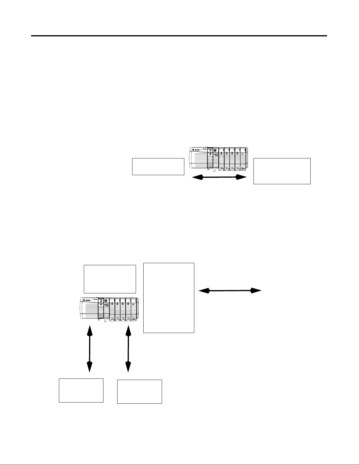
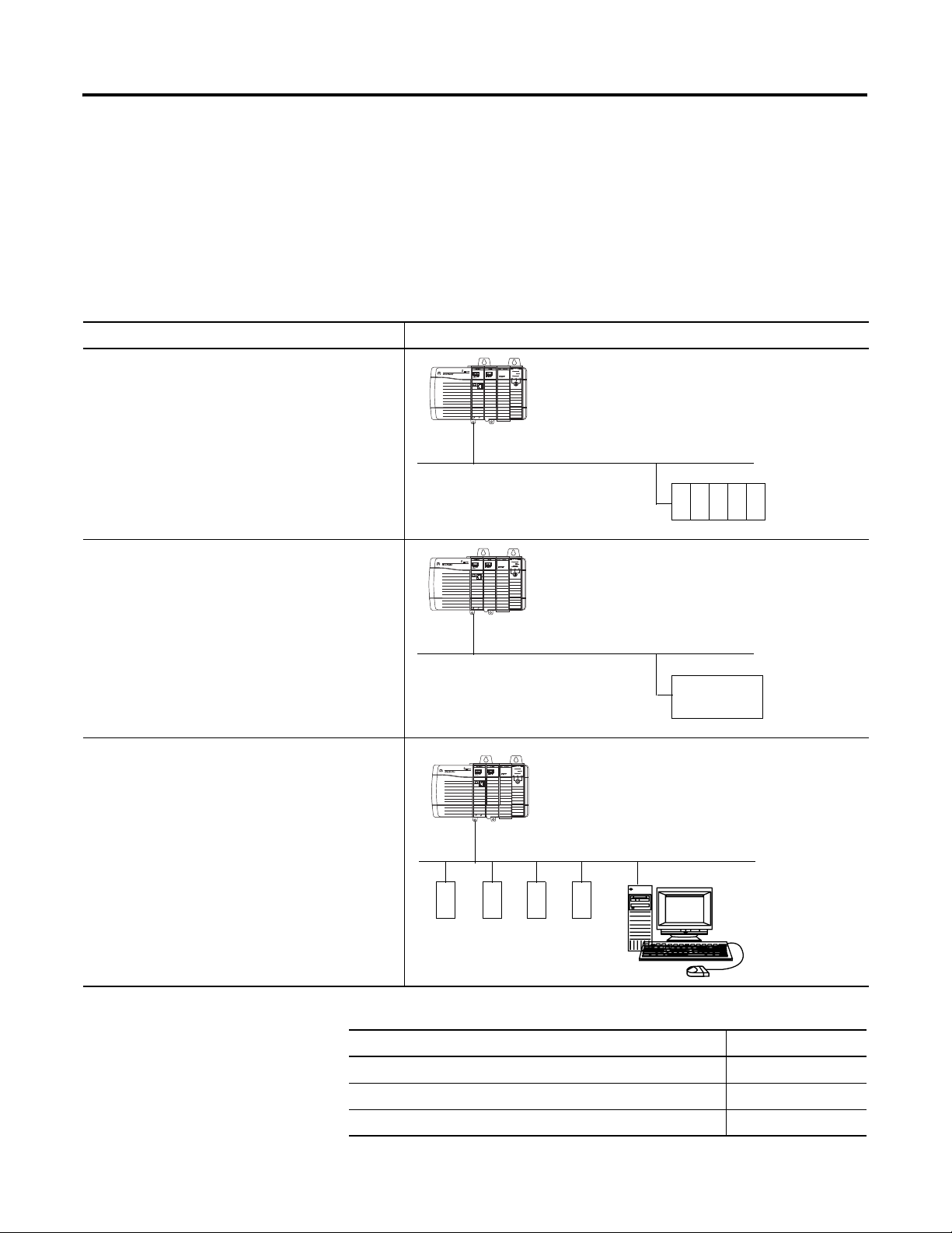
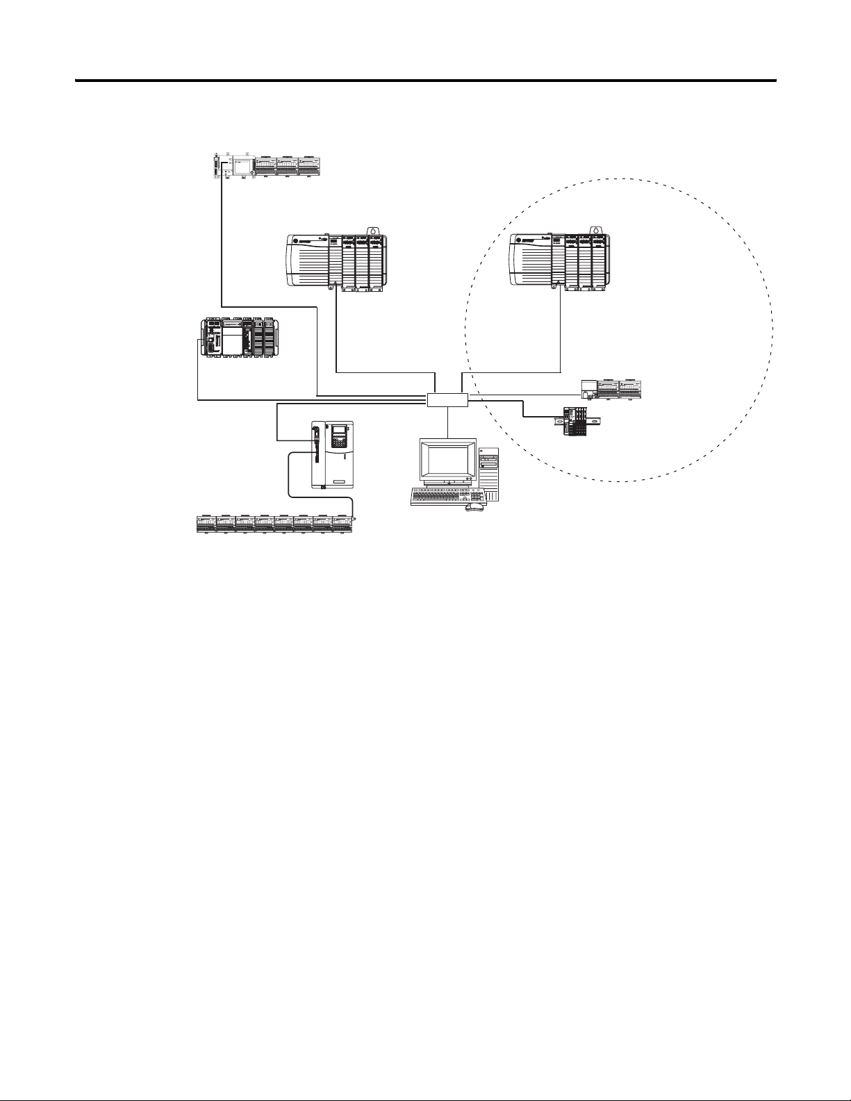
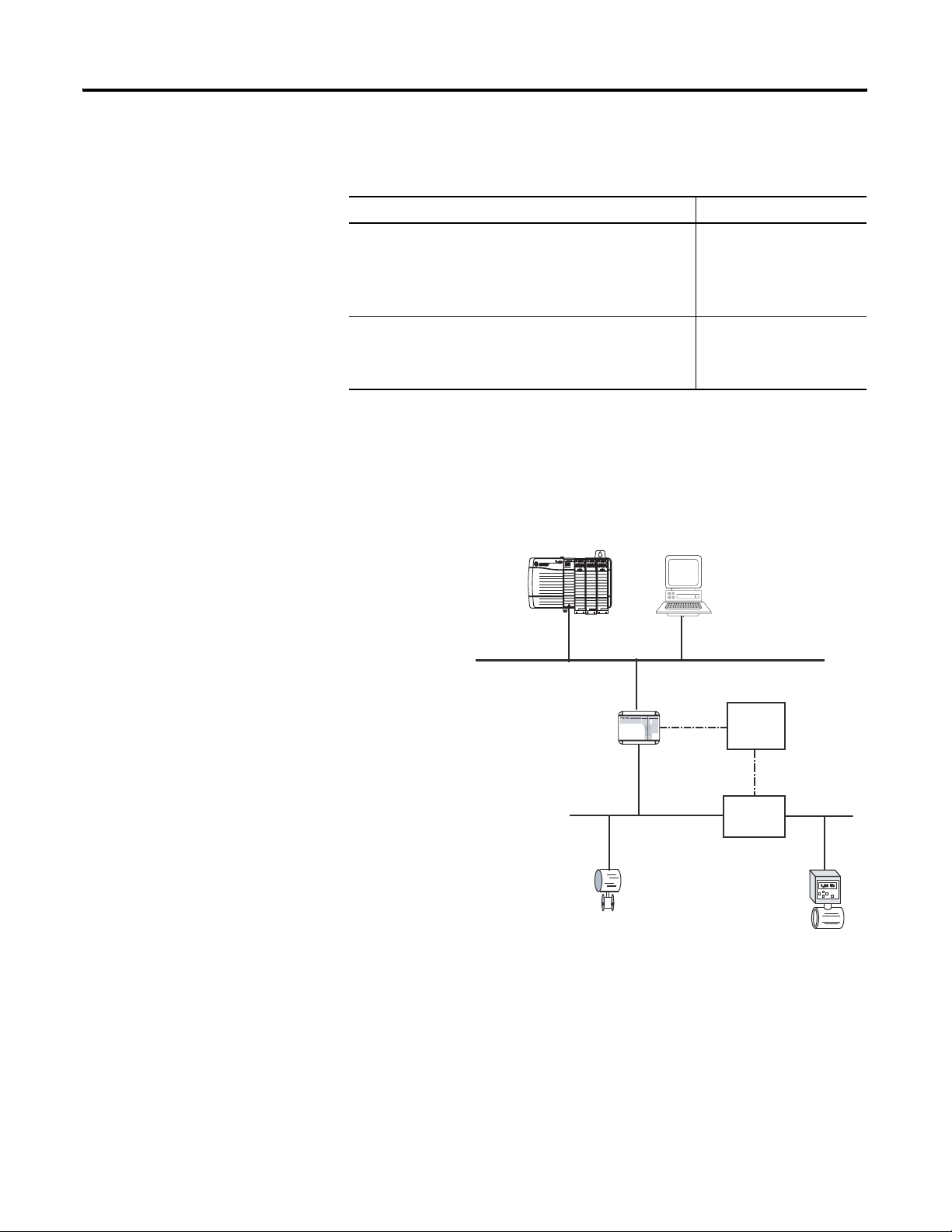
This chapter provides an overview of the ControlLogix system. The
ControlLogix system provides sequential, process, motion, and drive
control together with communication and I/O in a chassis-based
system. A simple ControlLogix system consists of a stand-alone
controller and I/O modules in a single chassis.
ControlLogix Controller
For a more flexible system, use:
• multiple controllers in a single chassis.
• multiple controllers joined across networks.
• I/O from multiple platforms that is distributed in many locations
and connected over multiple I/O links.
ControlLogix System Overview
Communication Interface
Modules in the Same
Chassis as the
ControlLogix Controller
EtherNet/IP Link
1756 I/O modules in the
Same chassis as the
ControlLogix Controller
Remote I/O Modules
Drives
}
ControlNet Link
EtherNet/IP Link
ControlNet Link
Computers
Other Controllers
11 Publication 1756-UM001G-EN-P - January 2007
SERCOS Drives
SERCOS Link
DeviceNet Link
Universal remote I/O Link
Page 12

12 ControlLogix System Overview
The ControlLogix controller is part of the Logix5000 family of
controllers. A ControlLogix system includes:
• the ControlLogix controller is available in different combinations
of user memory.
Controller Memory for Data
and Logic
I/O Nonvolatile
Backup Memory
1756-L55M12 750 KB 208 KB no
1756-L55M13 1.5 MB 208 KB no
1756-L55M14 3.5 MB 208 KB no
1756-L55M16 7.5 MB
208 KB no
≤ 3.5 MB of data
1756-L55M22 750 KB 208 KB Integrated
1756-L55M23 1.5 KB 208 KB Integrated
1756-L55M24 3.5 KB 208 KB Integrated
1756-L61 2 MB 478 KB
1756-L62 4 MB 478 KB
1756-L63 8 MB 478 KB
1756-L64 16 MB 478 KB
1756-L60M03SE 750 KB 478 KB
(1)
CompactFlash is optional and does not come with the controller.
CompactFlash
CompactFlash
CompactFlash
CompactFlash
CompactFlash
(1)
(1)
(1)
(1)
(1)
card
card
card
card
card
• RSLogix 5000 programming software.
• 1756 ControlLogix I/O modules that reside in a 1756 chassis.
• different communication modules for EtherNet/IP, ControlNet,
DeviceNet, DH+, and Universal remote I/O networks.
• other networks via third-party devices, such as Foundation
Fieldbus and the Highway Addressable Remote Transducer
(HART).
• a built-in serial port on every ControlLogix controller.
Publication 1756-UM001G-EN-P - January 2007
Page 13
ControlLogix System Overview 13
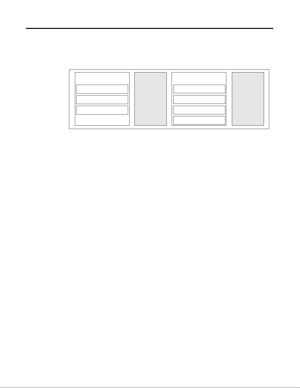
The ControlLogix controller divides resources between a Logix CPU
and a backplane CPU.
Logix CPU and Backplane CPU
Design
Logic and Data Memory
Program Source Code
Tag Data
RSLinx Tag Group Lists
• The Logix CPU executes application code and messages.
• The backplane CPU communicates with I/O and sends and
When you design a ControlLogix system, select:
• I/O devices.
• motion control and drives requirements.
• communication modules.
• controllers.
• chassis.
• power supplies.
• software.
I/O Memory
I/O Data
Logix
CPU
I/O Force Tables
Message Buffers
Produced/consumed Tags
Backplane
CPU
receives data from the backplane. This CPU operates
independently from the Logix CPU, so it sends and receives I/O
information asynchronous to program execution.
Install Hardware
To install a ControlLogix controller:
• install memory options.
– on a 1756-L55, install a memory board for additional memory.
– on a 1756-L6x, install a 1784-CF64 CompactFlash card for
nonvolatile memory.
See the chapter Maintain Nonvolatile Memory.
• connect the battery.
See the chapter Maintain the Battery.
• install the controller in the chassis.
Publication 1756-UM001G-EN-P - January 2007
Page 14

14 ControlLogix System Overview
• make serial connections.
See the chapter Directly Connect to the Controller via the Serial
Port.
• load controller firmware.
• make additional network connections.
See the chapter Communicate over Networks.
Publication 1756-UM001G-EN-P - January 2007
Page 15
Chapter
2
Directly Connect to the Controller via the Serial Port
Introduction
Connect the Controller to via the Serial Port
This chapter explains how to connect the controller to the serial port
and how to upload and download a project to the controller.
Topic Page
Connect the Controller to via the Serial Port 15
Configure the Serial Driver 17
Select the Controller Path 19
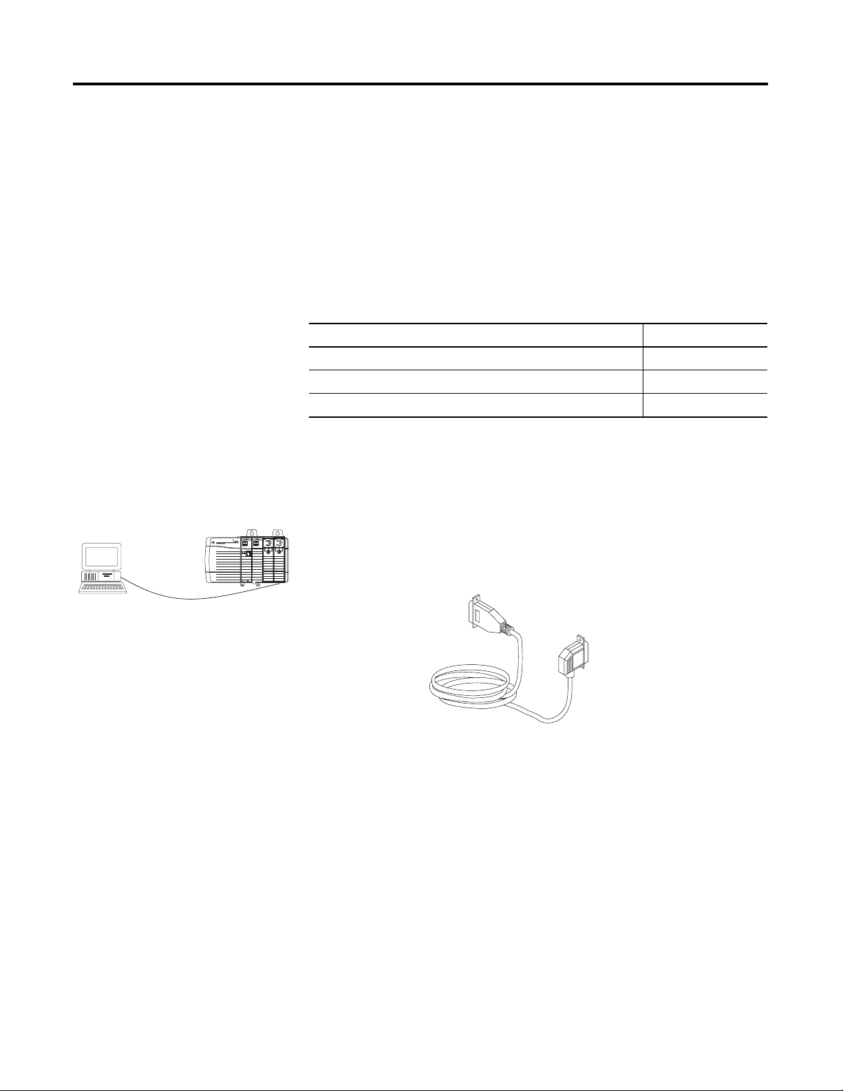
To connect a serial cable, perform this procedure.
1. Obtain a 1756-CP3 serial cable.
You can also use a 1747-CP3 cable from the SLC product family,
but once the cable is connected you cannot close the controller
door.
15 Publication 1756-UM001G-EN-P - January 2007
Page 16

16 Directly Connect to the Controller via the Serial Port
TIP
I
If you make your own serial cable:
• Limit the length to 15.2m (50 ft).
• Wire the connectors this way.
Workstation Controller
1 CD
2 RDX
3 TXD
4 DTR
COMMON
6 DSR
7 RTS
8 CTS
9
1 CD
2 RDX
3 TXD
4 DTR
COMMON
6 DSR
7 RTS
8 CTS
9
• Attach the shield to both connectors.
2. Connect the cable to the controller and to your workstation.
CP3 Cable
Publication 1756-UM001G-EN-P - January 2007
Page 17

Directly Connect to the Controller via the Serial Port 17
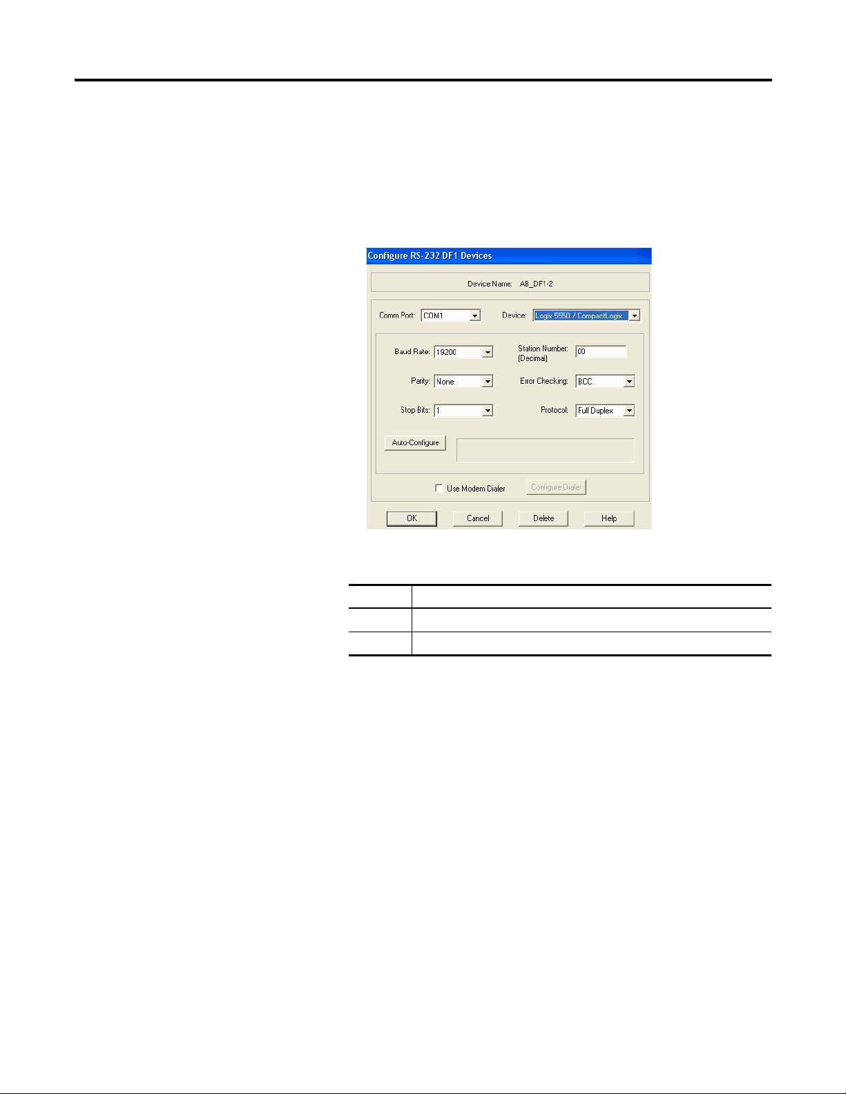
Configure the Serial Driver
Use RSLinx software to configure the RS-232 DF1 Device driver for
serial communication.
To configure the driver, perform this procedure.
1. From the Communications pull-down menu in RSLinx software,
choose Configure Drivers.
The Configure Drivers dialog appears.
2. From the Available Driver Types pull-down menu, choose the
RS-232 DF1 Device driver.
3. Click Add New.
The Add New RSLinx Driver dialog appears.
4. Type the driver name and click OK.
Publication 1756-UM001G-EN-P - January 2007
Page 18
18 Directly Connect to the Controller via the Serial Port
5. Specify the serial port settings.
a. From the Comm Port pull-down menu, choose the serial port
on the workstation to which the cable is connected.
b. From the Device pull-down menu, choose Logix 5550-Serial
Port.
c. Click Auto-Configure.
6. Was the auto configuration successful?
If Then
Yes Click OK.
No Go to step 5. and verify that you selected the correct Comm Port.
7. Click Close.
Publication 1756-UM001G-EN-P - January 2007
Page 19
Directly Connect to the Controller via the Serial Port 19
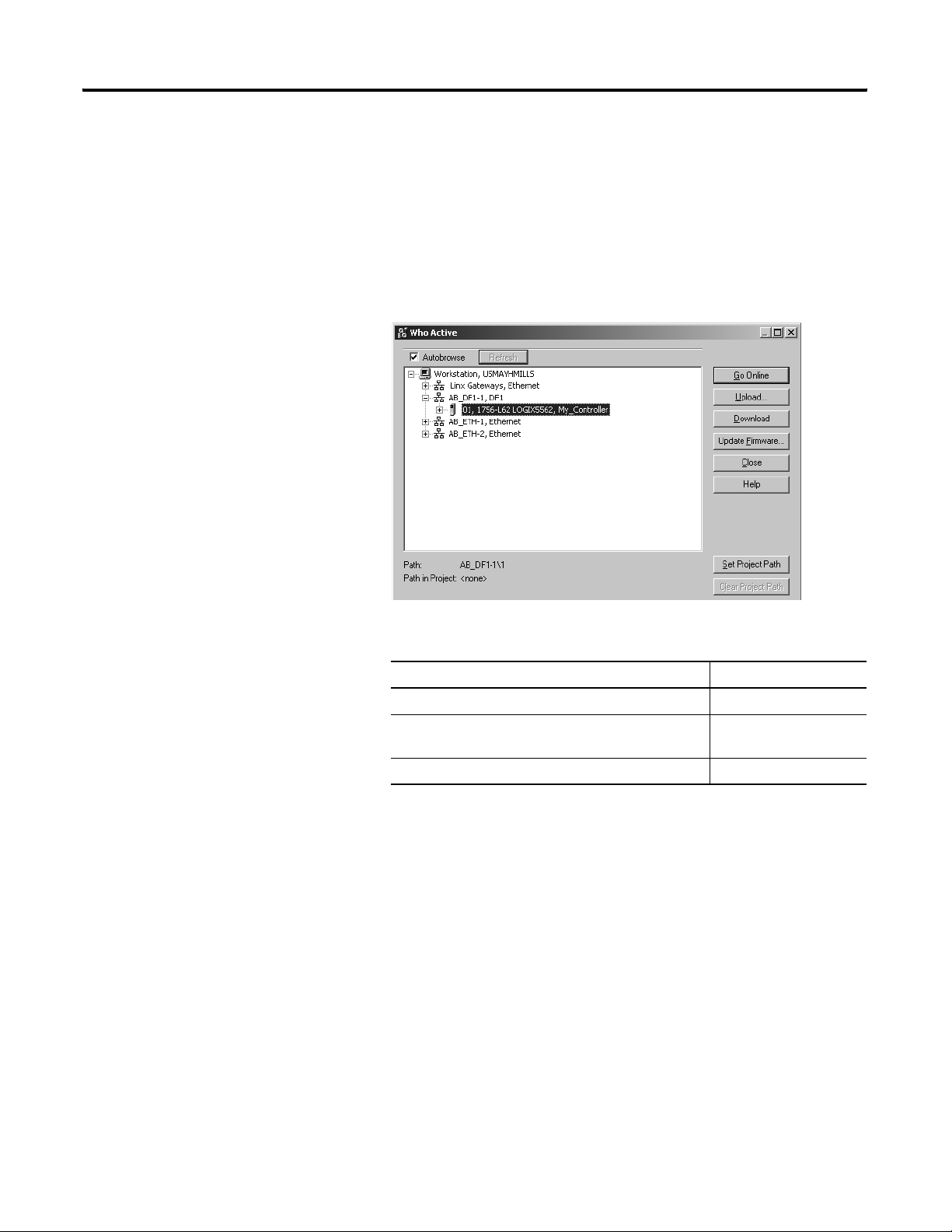
Select the Controller Path
In RSLogix 5000 programming software, to select the controller path,
perform this procedure.
1. Open an RSLogix 5000 project for the controller.
2. From the Communications pull-down menu, choose Who
Active.
3. Expand the communication driver to the level of the controller.
4. Select the controller.
To Choose
Monitor the project in the controller Go Online
Transfer a copy of the project from the controller to
RSLogix 5000 software
Transfer the open project to the controller Download
Upload
Publication 1756-UM001G-EN-P - January 2007
Page 20

20 Directly Connect to the Controller via the Serial Port
Notes:
Publication 1756-UM001G-EN-P - January 2007
Page 21
Communicate over Networks
e
Chapter
3
Introduction
Network Support Example
Control distributed (remote) I/O
• EtherNet/IP network
• ControlNet network
• DeviceNet network
• Universal remote I/O network
• Foundation Fieldbus network
• HART network
Produce/consume (interlock) data between controllers
• EtherNet/IP network
• ControlNet network
This chapter explains over what networks you can communicate.
ControlLogix Controller
Control Network
Distributed (remot
I/O Platform)
ControlLogix Controller
Control Network
Other Logix5000
Controller
Send and receive messages to and from other devices.
This includes access to the controller via RSLogix 5000
programming software.
• EtherNet/IP network
• ControlNet network
• DeviceNet (to devices only) network
• serial network
• DH+ network
• DH-485 network
Topic Page
EtherNet/IP Network Communication 22
ControlNet Network Communication 25
DeviceNet Network Communication 28
21 Publication 1756-UM001G-EN-P - January 2007
ControlLogix Controller
Control Network
Other Remote
Devices
Page 22

22 Communicate over Networks
Topic Page
Serial Network Communication 31
DH-485 Network Communication 37
DH+ Network Communication 41
Universal Remote I/O Communication 43
Foundation Fieldbus 45
HART 46
EtherNet/IP Network Communication
The EtherNet/IP network offers a full suite of control, configuration,
and data collection services by layering the Common Industrial
Protocol (CIP) over the standard Internet protocols, such as TCP/IP
and UDP. This combination of well-accepted standards provides the
capability required to both support information data exchange and
control applications.
The EtherNet/IP network also uses commercial, off-the-shelf Ethernet
components and physical media, providing you with a cost-effective
plant-floor solution.
For EtherNet/IP network communication, you have several
communication modules from which to choose.
EtherNet/IP Communication Modules
Functions Required
Module
• Control I/O modules.
• Require an adapter for distributed I/O on EtherNet/IP links.
• Communicate with other EtherNet/IP devices (messages).
• Share data with other Logix5000 controllers (produce/consume).
• Bridge EtherNet/IP links to route messages to devices on other
networks.
• Require remote access via Internet browser to tags in a local
ControlLogix controller.
• Communicate with other EtherNet/IP devices (messages).
• BridgesEtherNet/IP links to route messages to devices on other
networks.
• Does not support I/O or produced/consumed tags.
1756-ENBT
1756-EWEB
Publication 1756-UM001G-EN-P - January 2007
Page 23

Communicate over Networks 23
Required Software for EtherNet/IP Communication
Software Functions Requirement
RSLogix 5000 • Configure ControlLogix projects.
• Define EtherNet/IP communication.
RSLogix 5000
BOOTP/DHCP Utility
RSNetWorx for
EtherNet/IP
Assign IP addresses to devices on an
EtherNet/IP network.
• Configure EtherNet/IP devices by IP
addresses and/or host names.
• Provide bandwidth status.
Yes
No
RSLinx • Configure communication devices.
• Provide diagnostics.
• Establish communication between devices.
Yes
The EtherNet/IP communication modules:
• support messaging, produced/consumed tags, HMI, and
distributed I/O.
• encapsulate messages within standard TCP/UDP/IP protocol.
• share a common application layer with ControlNet and
DeviceNet networks.
• connect via RJ45 cable.
• support half/full duplex 10 MB or 100 MB operation.
• support standard switches.
In this example:
• The controllers produce and consume tags.
• The controllers initiate MSG instructions that send and receive
data or configure devices.
• The personal computer uploads and downloads projects to the
controllers.
• The personal computer configures devices on an EtherNet/IP
network.
Publication 1756-UM001G-EN-P - January 2007
Page 24
24 Communicate over Networks
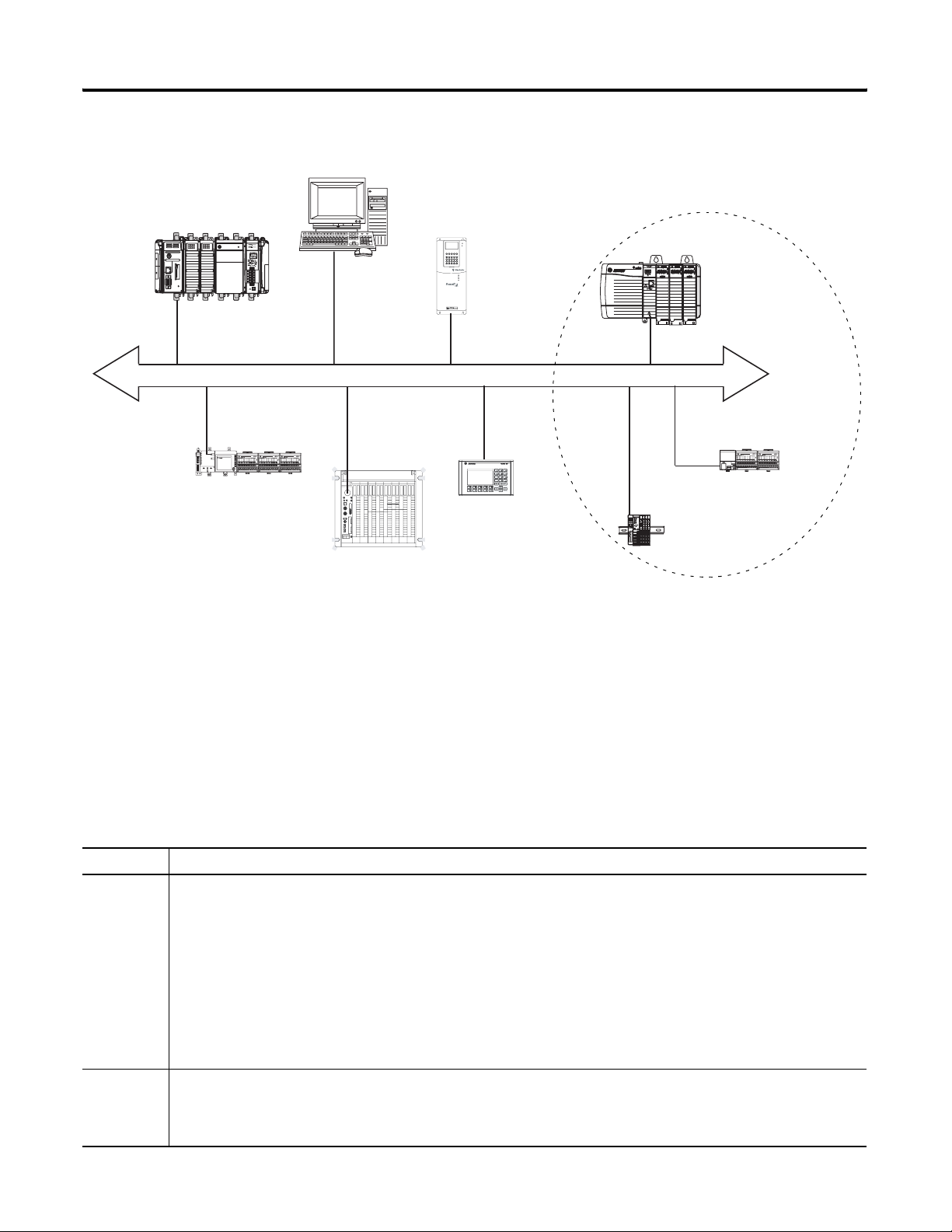
EtherNet/IP Network Overview
FlexLogix Controller with
1788-ENBT Module
Distributed I/O
CompactLogix Controller
with Integrated
EtherNet/IP Port
PowerFlex 700S AC
Drive with DriveLogix
LINK NET OK
ControlLogix
Controller with
1756-ENBT
Module
Switch
Workstation
LINK NET OK
1756-ENBT Module
(as an adapter) with 1756
I/O Modules
1734-AENT Adapter with
1734 I/O Modules
Connections Over an EtherNet/IP Network
1794-AENT Adapter with
1794 I/O Modules
You indirectly determine the number of connections the controller
uses by configuring the controller to communicate with other devices
in the system. Connections are allocations of resources that provide
more reliable communication between devices compared to
unconnected messages.
All EtherNet/IP connections are unscheduled. An unscheduled
connection is triggered by the requested packet interval (RPI) for I/O
control or the program, such as a MSG instruction. Unscheduled
messaging lets you send and receive data when needed.
The 1756 EtherNet/IP communication modules support 128 CIP
(Common Industrial Protocol) connections over an EtherNet/IP
network.
Publication 1756-UM001G-EN-P - January 2007
Page 25

Communicate over Networks 25
Additional Resources
For additional information, consult these publications:
• EtherNet/IP Modules in Logix5000 Control Systems User Manual,
publication ENET-UM001
• Logix5000 Controllers Design Considerations Reference Manual,
publication 1756-RM094
ControlNet Network Communication
The ControlNet network is a real-time control network that provides
high-speed transport of both time-critical I/O and interlocking data
and messaging data, including uploading and downloading of
programming and configuration data on a single physical-media link.
The ControlNet network’s highly-efficient data transfer capability
significantly enhances I/O performance and peer-to-peer
communication in any system or application.
The ControlNet network is highly deterministic and repeatable and
remains unaffected as devices are connected or disconnected from the
network. This robust quality results in dependable, synchronized, and
coordinated real-time performance.
The ControlNet network often functions as:
• a substitute/replacement for the remote I/O (RIO) network
because the ControlNet network adeptly handles large numbers
of I/O points.
• a backbone to multiple distributed DeviceNet networks.
• a peer interlocking network.
For ControlNet communication, you have two communication
modules from which to choose.
ControlNet Communication Modules
Functions Required
Module
• Control I/O modules.
• Require an adapter for distributed I/O on ControlNet links.
• Communicate with other ControlNet devices (messages).
• Share data with other Logix5000 controllers (produce/consume).
• Bridge ControlNet links to route messages to devices on other networks.
• Perform same functions as a 1756-CNB module.
• Support redundant ControlNet media.
Publication 1756-UM001G-EN-P - January 2007
1756-CNB
1756-CNBR
Page 26

26 Communicate over Networks
Required Software for ControlNet Communication
Software Functions Requirement
RSLogix 5000 • Configure ControlLogix projects.
• Define ControlNet communication.
RSNetWorx
for ControlNet
RSLinx • Configure communication devices.
• Configure ControlNet devices by IP addresses
and/or host names.
• Schedule a network.
• Provide diagnostics.
• Establish communication between devices.
Yes
The 1756-CNB and 1756-CNBR ControlNet communication modules:
• support messaging, produced/consumed tags and distributed
I/O.
• share a common application layer with DeviceNet and
EtherNet/IP networks.
• require no routing tables.
• support the use of coax and fiber repeaters for isolation and
increased distance
• support redundant media (1756-CNBR module only)
In this example:
• the controllers produce and consume tags.
• the controllers initiate MSG instructions that send and receive
data or configure devices.
• the personal computer uploads and downloads projects to the
controllers.
• the personal computer configures devices on a ControlNet
network, and it can configure the network itself.
Publication 1756-UM001G-EN-P - January 2007
Page 27
CompactLogix Controller
Communicate over Networks 27
ControlNet Network Overview
Workstation
Distributed I/O
PowerFlex 700S AC
Drive with DriveLogix
1756-CNB Module
(as an adapter) with
1756 I/O Modules
ControlNet Network
FlexLogix Controller with
1788-CNC Card
PanelView Terminal
PLC-5/40C Controller
1794-ACN15 Adapter
with 1794 I/O Modules
1734-ACNR Adapter with
1734 I/O Modules
Connections Over a ControlNet Network
You indirectly determine the number of connections the controller
uses by configuring the controller to communicate with other devices
in the system. Connections are allocations of resources that provide
more reliable communication between devices compared to
unconnected messages.
ControlNet Connections
Connection Definition
Scheduled
(unique to a
ControlNet
network)
Unscheduled An unscheduled connection is a message transfer between controllers that is triggered by the requested packet interval
A scheduled connection is unique to ControlNet communication. A scheduled connection lets you send and receive data
repeatedly at a predetermined interval, which is the requested packet interval (RPI). For example, a connection to an I/O
module is a scheduled connection because you repeatedly receive data from the module at a specified interval. Other
scheduled connections include connections to:
• communication devices.
• produced/consumed tags.
On a ControlNet network, you must use RSNetWorx for ControlNet software to enable all scheduled connections and
establish a network update time (NUT). Scheduling a connection reserves network bandwidth to specifically handle the
connection.
(RPI) or the program, such as a MSG instruction. Unscheduled messaging lets you send and receive data when you need to.
Unscheduled connections use the remainder of network bandwidth after scheduled connections are allocated.
Publication 1756-UM001G-EN-P - January 2007
Page 28

28 Communicate over Networks
The 1756-CNB and 1756-CNBR communication modules support 64
CIP connections over a ControlNet network. However, for optimal
performance, only configure 48 connections for each module.
Additional Resources
For additional information, consult these publications:
• ControlNet Modules in Logix5000 Control Systems User Manual,
publication CNET-UM001
• Logix5000 Controllers Design Guidelines Reference Manual,
publication 1756-RM094
DeviceNet Network Communication
The DeviceNet network uses the Common Industrial Protocol (CIP) to
provide the control, configuration, and data collection capabilities for
industrial devices. The DeviceNet network uses the proven Controller
Area Network (CAN) technology, which lowers installation costs and
decreases installation time and costly downtime.
A DeviceNet network provides access to the intelligence present in
your devices by letting you connect devices directly to plant-floor
controllers without having to hard wire each device into an I/O
module.
DeviceNet communication requires a 1756-DNB DeviceNet
communication module. The DeviceNet network uses the Common
Industrial Protocol (CIP) to provide the control, configuration, and
data collection capabilities for industrial devices.
Functions Required Module
• Control I/O modules.
• Require an adapter for distributed I/O on DeviceNet links.
• Communicate with other DeviceNet devices (messages).
• Link an EtherNet/IP network to a DeviceNet network.
• Require multiple networks.
• Link a ControlNet network to a DeviceNet network.
• Require multiple networks.
1756-DNB
1788-EN2DN
1788-CN2DN
Publication 1756-UM001G-EN-P - January 2007
Page 29
Communicate over Networks 29
Required Software for DeviceNet Communication
Software Functions Requirement
RSLogix 5000 • Configure ControlLogix projects.
• Define EtherNet/IP communication.
RSNetWorx for
DeviceNet
• Configure DeviceNet devices.
• Define the scan list for those devices.
RSLinx • Configure communication devices.
• Provide diagnostics.
• Establish communication between devices.
The DeviceNet communication module:
• supports messaging to devices, not controller to controller.
• shares a common application layer with ControlNet and
EtherNet/IP networks.
• offers diagnostics for improved data collection and fault
detection.
• requires less wiring than traditional, hardwired systems.
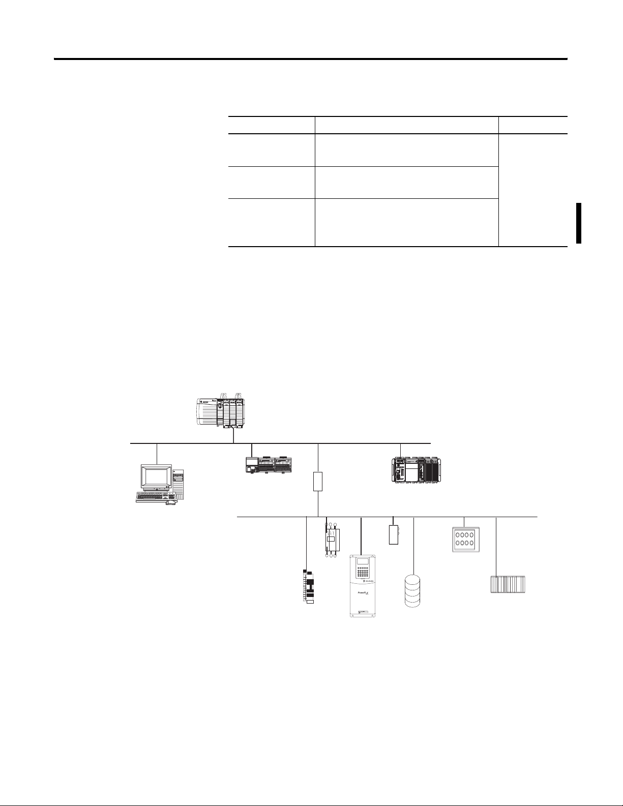
ControlLogix DeviceNet Network Overview
ControlLogix Controller
with 1756-ENBT Module
EtherNet/IP Network
CompactLogix Controller
FLEX Adapter and I/O
Linking
Devices
Yes
Personal Computer
Input/output
Devices
Motor
Starter
PowerFlex
ac Drive
DeviceNet Network
Sensor
PWR
PWR
STS
STS
PORT
MOD
PORT
NET A
MOD
NET B
NET A
NET B
Indicator
Lights
Publication 1756-UM001G-EN-P - January 2007
Pushbutton
Cluster
Bar Code
Scanner
Page 30

30 Communicate over Networks
Connections over DeviceNet
The ControlLogix controller requires two connections for each
1756-DNB module. One connection is for module status and
configuration. The other connection is a rack-optimized connection
for the device data.
The 1756-DNB module has fixed sections of memory for the input and
output data of the DeviceNet devices on the network. Each device on
your network requires either some input or output memory of the
scanner. Some devices both send and receive data, so they need both
input and output memory. The 1756-DNB module supports up to:
• 124 DINTs of input data.
• 123 DINTs of output data.
Additional Resources
For more information, consult these publications:
• DeviceNet Modules in Logix5000 Control Systems User Manual,
publication DNET-UM004
• Logix5000 Controllers Design Considerations Reference Manual,
publication 1756-RM094
Publication 1756-UM001G-EN-P - January 2007
Page 31

Communicate over Networks 31
Serial Network Communication
Mode Functions
DF1
point-to-point
Communication between the controller and one other DF1-protocol-compatible device.
This is the default system mode. Default parameters are:
The ControlLogix controller has one built-in RS-232 port.
Functions Required
• Communicates between a controller and other
DF1-compatible devices using DF1 protocols.
• Uses modems.
• Controls SCADA applications.
• Controls ASCII devices.
• Requires additional RS-232 connections.
• Requires RS-422 and/or RS-485 connections.
IMPORTANT
DF1 Modes for Logix5000 Controllers
Limit the length of RS-232 serial cables to 15.2 m (50 ft).
Built-in serial port
1756-MVI
1756-MVID
• Baud Rate: 19200
• Data Bits: 8
• Parity: None
• Stop Bits: 1
• Control Line: No Handshake
• RTS send Delay: 0
• RTS Off Delay: 0
This mode is typically used to program the controller through its serial port.
DF1 master
mode
DF1 slave • Using a controller as a slave station in a master/slave serial communication network.
User • Communication with ASCII devices.
DH-485 Communication with other DH-485 devices multi-master, token passing network allowing programming and peer-to-peer
• Control of polling and message transmission between the master and slave nodes.
• The master/slave network includes one controller configured as the master node and up to 254 slave nodes. Link slave
nodes using modems or line drivers.
• A master/slave network can have node numbers from 0...254. Each node must have a unique node address. Also, at
least 2 nodes must exist to define your link as a network, one master and one slave station being the two nodes.
• When there are multiple slave stations on the network, link slave stations using modems or line drivers to the master.
When you have a single slave station on the network, you do not need a modem to connect the slave station to the
master. You can configure the control parameters for no handshaking. You can connect 2...255 nodes to a single link. In
DF1 slave mode, a controller uses DF1 half-duplex protocol.
• One node is designated as the master and it controls who has access to the link. All the other nodes are slave stations
and must wait for permission from the master before transmitting.
• This requires your program to use ASCII instructions to read and write data from and to an ASCII device.
messaging.
Publication 1756-UM001G-EN-P - January 2007
Page 32

32 Communicate over Networks
Communicate with DF1 Devices
You can configure the controller as a master or slave on a serial
communication network. Use serial communication to get information
to and from remote controllers (stations) when:
• the system contains three or more stations.
• communication occurs on a regular basis and requires
leased-line, radio, or power-line modems.
ControlLogix DF1 Device Communication
EtherNet/IP
Network
RS-232 Connection
RS-232 Connection
Modem
DH+ Connection
RS-232 Connection
Modem
Modem
Publication 1756-UM001G-EN-P - January 2007
Page 33

Communicate over Networks 33
To configure the controller for DF1 communication, perform this
procedure.
1. In the Controller Organizer of RSLogix 5000 programming
software, right-click your controller and select Properties.
The Controller Properties dialog appears.
2. Click the Serial Port tab.
3. From the Mode pull-down menu, choose System.
4. Specify DF1 communication settings.
5. Click the System Protocol tab.
Publication 1756-UM001G-EN-P - January 2007
Page 34

34 Communicate over Networks
6. From the Protocol pull-down menu, choose DF1 Point-to-Point.
7. Specify DF1 system protocol settings.
8. Click OK.
Additional Resources
For additional information, consult these publications:
• Logix5000 Controllers General Instructions Reference Manual,
publication 1756-RM003
• SCADA System Application Guide, publication AG-UM008.
Communicate with ASCII Devices
When you configure the serial port for user mode, you can use it to:
• read ASCII characters from a weigh scale module or bar code
reader.
• send and receive messages from an ASCII-triggered device, such
as a MessageView terminal.
Connection from the Controller’s Serial Port to the ASCII Device
To communicate with ASCII devices, perform this procedure.
1. In the Controller Organizer of RSLogix 5000 programming
software, right-click your controller and select Properties.
Publication 1756-UM001G-EN-P - January 2007
Page 35

Communicate over Networks 35
The Controller Properties dialog appears.
2. Click the Serial Port tab.
3. From the Mode pull-down menu, choose User.
4. Specify ASCII communication settings.
5. Click the User Protocol tab.
6. Specify ASCII user protocol settings.
7. Click OK.
Publication 1756-UM001G-EN-P - January 2007
Page 36

36 Communicate over Networks
The controller supports several ladder diagram (LD) and structured
text (ST) instructions to manipulate ASCII characters.
Read and Write ASCII Characters
Instruction Code Command
ABL Determine when the buffer contains termination characters
ACB Count the characters in the buffer
ACL Clear the buffer
Clear out ASCII Serial Port instructions that are currently
executing or are in the queue
AHL Obtain the status of the serial port control lines
Turn on or off the DTR signal
Turn on or off the RTS signal
ARD Read a fixed number of characters
ARL Read a varying number of characters, up to and including the
first set of termination characters
AWA Send characters and automatically append one or two
additional characters to mark the end of the data
AWT Send characters
Create and Modify Strings of ASCII Characters
Instruction Code Command
CONCAT Add characters to the end of a string
DELETE Delete characters from a string
FIND Determine the starting character of a sub-string
INSERT Insert characters into a string
MID Extract characters from a string
Convert Data to or from ASCII Characters
Instruction Code Command
STOD Convert the ASCII representation of an integer value to a SINT,
INT, DINT, or REAL value
STOR Convert the ASCII representation of a floating-point value to a
REAL value
DTOS Convert a SINT, INT, DINT, or REAL value to a string of ASCII
characters
RTOS Convert a REAL value to a string of ASCII characters
Publication 1756-UM001G-EN-P - January 2007
UPPER Convert the letters in a string of ASCII characters to upper case
LOWER Convert the letters in a string of ASCII characters to lower case
Page 37

Communicate over Networks 37
Additional Resources
For additional information, consult these publications:
• Logix5000 Controllers General Instructions Reference Manual,
publication 1756-RM003
• Logix5000 Controllers Common Procedures Programming
Manual, publication 1756-PM001
Modbus Support
To use Logix5000 controllers on the Modbus protocol, establish a
serial port connection and execute a specific ladder-logic routine. The
controller project is available with RSLogix 5000 programming
software.
DH-485 Network Communication
Additional Resources
For additional information, consult Using Logix5000 Controllers as
Masters or Slaves on Modbus Application Solution, publication
CIG-AP129.
For DH-485 communication, use the serial port of the controller. The
controller can send and receive messages to and from other
controllers on a DH-485 network. The DH-485 connection supports
remote programming and monitoring via RSLogix 5000 programming
software. However, excessive traffic over a DH-485 connection can
adversely affect overall performance and lead to timeouts and
decreased RSLogix 5000 configuration performance.
IMPORTANT
The DH-485 protocol uses RS-485 half-duplex as its physical interface.
RS-485 is a definition of electrical characteristics, not a protocol. You
can configure the RS-232 port of the ControlLogix controller to act as a
DH-485 interface. By using a 1761-NET-AIC converter and the
appropriate RS-232 cable (1756-CP3 or 1747-CP3), a ControlLogix
controller can send and receive data on a DH-485 network.
Use Logix5000 controllers on DH-485 networks only when you
want to add controllers to an existing DH-485 network. For new
applications with Logix5000 controllers, we recommend you
use networks in the NetLinx open architecture.
Publication 1756-UM001G-EN-P - January 2007
Page 38

38 Communicate over Networks
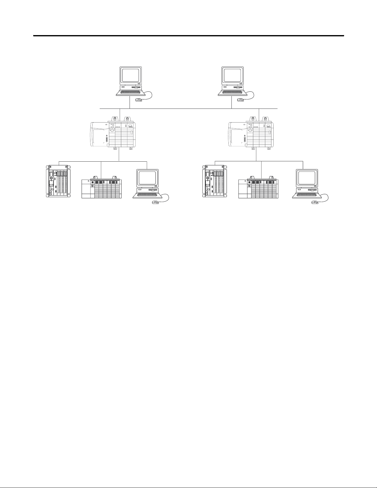
ControlLogix DH-485 Network Communication Overview
Connection from ControlLogix
Controller to Port 1 or Port 2
1761-NET-AIC+
Converter
DH-485 Network
ControlLogix Controller
1747-AIC
Programmable
Controller Isolated
Link Coupler
SLC 5/03 Controller
On the DH-485 network, the ControlLogix controller can send and
receive messages to and from other controllers.
IMPORTANT
A DH-485 network consists of multiple cable segments. Limit
the total length of all the segments to 1219 m (4000 ft).
For the controller to operate on a DH-485 network, you need a
1761-NET-AIC interface converter for each controller you want to put
on the DH-485 network.
You can have two controllers for each 1761-NET-AIC converter, but
you need a separate cable for each controller. Connect the serial port
of the controller to either port 1 or port 2 of the 1761-NET-AIC
converter. Use the RS-485 port to connect the converter to the DH-485
network.
Cable Selection
Connection Required Cable
Port 1
DB-9 RS-232, DTE connection
Port 2
Mini-DIN 8 RS-232 connection
1747-CP3
or
1761-CBL-AC00
1761-CBL-AP00
or
1761-CBL-PM02
Publication 1756-UM001G-EN-P - January 2007
Page 39

Communicate over Networks 39
To communicate with DH-485 devices, perform this procedure.
1. In the Controller Organizer of RSLogix 5000 programming
software, right-click your controller and select Properties.
The Controller Properties dialog appears.
2. Click the Serial Port tab.
3. From the Mode pull-down menu, choose System.
4. Specify DH-485 communication settings.
The baud rate specifies the communication rate for the DH-485
port. All devices on the same DH-485 network must be
configured for the same baud rate.
a. From the Baud Rate pull-down menu, choose 9600 or 19200
kbps.
Publication 1756-UM001G-EN-P - January 2007
Page 40

40 Communicate over Networks
Click the System Protocol tab.
5. Specify system protocol settings.
The station address specifies the node address of the controller
on the DH-485 network.
a. From the Station Address pull-down menu, choose a station
address number from 1...31, decimal.
To optimize network performance, assign station addresses in
sequential order.
Assign initiators, such as personal computers, the lowest
station address numbers to minimize the time required to
initialize the network.
The maximum station address specifies the maximum node
address of all the devices on the DH-485 network.
b. From the Max Station Address pull-down menu, choose a
maximum station address number from 1...31, decimal.
To optimize network performance, make sure:
•the maximum station address is the highest node number
being used on the network.
•that all the devices on the same DH-485 network have the
same selection for the maximum station address.
Publication 1756-UM001G-EN-P - January 2007
The token hold factor is the number of transmissions (plus
retries) that an address holding a token can send onto the data
link each time that it receives the token.
Page 41

Communicate over Networks 41
c. In the Token Hold Factor box, enter a token hold factor value
from 1...4.
The default is 1.
6. Click OK.
Additional Resources
For more information, consult Data Highway/Data Highway Plus/Data
Highway II/Data Highway-485 Cable Installation Manual, publication
1770-6.2.2.
DH+ Network Communication
For DH+ network communication, use a 1756-DHRIO module to
exchange information between:
• PLC controllers and SLC controllers.
• ControlLogix controllers and PLC or SLC controllers.
• ControlLogix controllers
Functions Required
• Share data with program maintenance on a plantwide and
cell-level basis.
• Send data regularly.
• Transfer information between controllers.
You can connect a maximum of 32 stations to a single DH+ link.
• Channel A supports 57.6 Kbps, 115.2 Kbps, and 230.4 Kbps.
• Channel B supports 57.6 Kbps and 115.2 Kbps.
.
Module
1756-DHRIO
Publication 1756-UM001G-EN-P - January 2007
Page 42
42 Communicate over Networks
ControlLogix DH+ Network Communication Overview
DH+ Network
PLC-5 Processor
SLC 500 Controller
Data Collection and
Recipe Management
EtherNet/IP Network
ControlLogix
Controller
RSView Station SLC 500 ControllerPLC-5 Controller RSView Station
Workstation
ControlLogix
Controller
DH+ Network
Communicate over a DH+ Network
For the controller to communicate to a workstation or other device
over a DH+ network, use RSLinx software to:
• specify a unique link ID for each ControlLogix backplane and
additional network in the communication path.
• configure the routing table for the 1756-DHRIO module.
The 1756-DHRIO module can route a message through up to four
communication networks and three chassis. This limit applies only to
the routing of a message and not to the total number of networks or
chassis in a system.
Additional Resources
For additional information, consult the ControlLogix Data Highway
Plus - Universal Remote I/O Module User Manual, publication
1756-UM514.
Publication 1756-UM001G-EN-P - January 2007
Page 43

Communicate over Networks 43
Universal Remote I/O Communication
For universal remote I/O communication, use a 1756-DHRIO module.
Functions Required
Module
• Establish connections between controllers and I/O adapters.
• Send data regularly.
• Distribute control so that each controller has its own I/O.
• Communicate with a supervisory controller.
• Use an RIO scanner.
• Communicate with as many as 32 RIO adapters.
• Support HART (Highway Addressable Remote Transducer) devices.
• Use scheduled connections to update data on a ControlLogix
controller.
1756-DHRIO
1757-ABRIO
When a channel on the 1756-DHRIO module is configured for remote
I/O, the module acts as a scanner for a universal remote I/O network.
The controller communicates to the module to send and receive the
I/O on the universal remote I/O network.
ControlLogix Universal Remote I/O Communication Overview
ControlLogix Controller
Universal Remote I/O Network
1771-ASB and I/O Modules
1746-ASB and I/O Modules
PLC-5 Controller in Adapter Mode
1794-ASB and I/O Modules
Publication 1756-UM001G-EN-P - January 2007
Page 44

44 Communicate over Networks
Communicate Over a Universal Remote I/O Network
For the controller to control I/O over a universal remote I/O network,
you must perform this procedure.
1. Configure the remote I/O adapter.
2. Lay out the remote I/O network cable.
3. Connect the remote I/O network cable.
4. Configure the scanner channel.
As you design your remote I/O network, remember that:
• all devices connected to a remote I/O network must
communicate using the same communication rate. These rates
are available for remote I/O:
– 57.6 Kbps
– 115.2 Kbps
– 230.4 Kbps
• you must assign unique partial and full racks to each channel
used in remote I/O scanner mode.
Both channels of a 1756-DHRIO module cannot scan the same
partial or full rack address. Both module channels can
communicate to 00...37 octal or 40...77 octal, but each channel
can only communicate with one address at a time in whichever
of these two ranges it falls.
• a channel can have up to 32 rack numbers with 32 physical
devices connected to it.
• a channel can have a maximum of 16 block-transfer
connections.
Additional Resources
For additional information, consult these publications:
• ControlLogix Data Highway Plus - Universal Remote I/O Module
User Manual, publication 1756-UM514
• Process Remote I/O Interface Module User Manual, publication
1757-UM007
Publication 1756-UM001G-EN-P - January 2007
Page 45
Communicate over Networks 45
Foundation Fieldbus
Foundation Fieldbus is an open interoperable fieldbus designed for
process control instrumentation.
Application Required Linking Device
• Bridge an EtherNet/IP network to Foundation Fieldbus.
1757-FFLD
• Connect via a low-speed serial (H1) and high-speed
Ethernet (HSE) network connections.
• Access devices directly via an OPC server.
• Connect via low-speed serial (H1) connections.
1788-CN2FF
• Bridge a ControlNet network to a Foundation Fieldbus.
• Support redundant ControlNet media.
Foundation Fieldbus distributes and executes control in the device.
The Foundation Fieldbus linking device:
• bridges from an Ethernet/IP network to an H1 connection.
• accepts either HSE or EtherNet/IP messages and converts them
to the H1 protocol.
Foundation Fieldbus Overview
ControlLogix Controller with
a 1756-ENBT Module
LINK NET OK
RSFieldbus
24V dc
Power
Supply
1757-FFLD Linking Device
FOUNDATION F
iel
dbu
s
H1
H1-1
H1
H1-2
F
OUNDATIO
N
F
iel
dbu
s
H1
H1-3
L
inking
D
evi
ce
H1
H1-4
STATU
S
WDOG
BA
TT
NS
1
MOD
E
Power
Conditioner
Field Device Field Device
Additional Resources
For additional information, consult these devices:
• RSFieldbus User Manual, publication RSFBUS-UM001
• Foundation Fieldbus Linking Device User Manual, publication
1757-UM010
Publication 1756-UM001G-EN-P - January 2007
Page 46

46 Communicate over Networks
HART (Highway Addressable Remote Transducer) Protocol
HART is an open protocol designed for process control
instrumentation.
Functions Required Device
• Acquire data or control application with slow update
requirements, such as a tank farm.
• Does not require external hardware to access HART signal.
• Does not provide a direct connection to asset management
software.
• Contain analog and HART in one module.
• Does not require external hardware to access HART signal.
• Transmit HART commands as unscheduled messages.
• Support asset management software to HART device
• Contain analog and HART in one module.
• Provide instrumentation in hazardous locations (FLEX Ex).
• Transmit HART commands as unscheduled messages.
• Directly connect asset management software to HART devices.
Prosoft interface
MVI56-HART
Spectrum analog
I/O modules
• 1756sc-IF8H
• 1756sc-OF8H
1794 FLEX I/O
modules
• 1794-IE8H
• 1794-OE8H
1797 FLEX Ex I/O
modules
• 1797-IE8H
• 1797-OE8H
The HART protocol combines digital signals with analog signals to
ready the digital signal for the process variable (PV). The HART
protocol also provides diagnostic data from the transmitter.
HART Protocol Overview
ControlLogix Controller
with 1756SC-IF8H or
1756SC-OF8H Modules
HART Field Devices
Additional Resources
Publication 1756-UM001G-EN-P - January 2007
For additional information, consult these resources:
• FLEX Ex HART Analog Modules User Manual, publication
1797-6.5.3
• Encompass website at http://automation/rockwell/encompass
Page 47

Chapter
Manage Controller Communication
4
Introduction
Connection Overview
This chapter explains how to manage controller communication.
Topic Page
Connection Overview 47
Produce and Consume (Interlock) Data 48
Send and Receive Messages 49
Calculate Connection Use 50
A Logix5000 system uses a connection to establish a communication
link between two devices. The types of connections include:
• controller-to-local I/O modules or local communication
modules.
• controller-to-remote I/O or remote communication modules.
• controller-to-remote I/O (rack-optimized) modules.
• produced and consumed tags.
• messages.
• controller access by RSLogix 5000 programming software.
• controller access by RSLinx software for HMI or other
applications.
Additional Resources
For additional information, consult Logix5000 Controllers Design
Considerations Reference Manual, publication 1756-RM094.
47 Publication 1756-UM001G-EN-P - January 2007
Page 48

48 Manage Controller Communication
Produce and Consume (Interlock) Data
Tag Type Description
Produced A produced tag lets other controllers to consume the tag, which means that a
Consumed Each consumed tag requires one connection for the controller that is consuming the
The controller supports the ability to produce (broadcast) and
consume (receive) system-shared tags over ControlNet or EtherNet/IP
networks. Produced and consumed tags each require connections.
Over a ControlNet network, produced and consumed tags are
scheduled connections.
Tag Types
controller can receive the tag data from another controller. The producing controller
uses one connection for the produced tag and one connection for each consumer. The
controller’s communication device uses one connection for each consumer.
As you increase the number of controllers that can consume a produced tag, you also
reduce the number of connections the controller and communication device have
available for other operations, such as communication and I/O.
tag. The controller’s communication device uses one connection for each consumer.
For two controllers to share produced or consumed tags, both must
be attached to the same network. You cannot bridge produced and
consumed tags over two networks.
The number of available connections limits the number of tags that
can be produced or consumed. If the controller uses all of its
connections for I/O and communication devices, no connections are
left for produced and consumed tags.
Available Connections
Device Supported Connections
ControlLogix controller 250
• 1756-ENBT module
• 1756-EWEB module
• 1756-CNB module
• 1756-CNBR module
128
64
48 is the recommended maximum.
Additional Resources
For additional information, consult these publications:
• Logix5000 Controllers Common Procedures Programming
Manual, publication 1756-PM001
• Logix5000 Controllers Design Considerations Reference Manual,
publication 1756-RM094
Publication 1756-UM001G-EN-P - January 2007
Page 49

Manage Controller Communication 49
Send and Receive Messages
Messages transfer data to other devices, such as other controllers or
operator interfaces. Some messages use unscheduled connections to
send or receive data. These connected messages can leave the
connection open (cache) or close the connection when the message is
done transmitting. Each message uses one connection, regardless of
how many devices are in the message path. To conserve connections,
configure one message to read from or write to multiple devices.
Message Types
Message Type Communication
Method
CIP data table read or write N/A Yes Yes
PLC-2, PLC-3, PLC-5, or SLC
(all types)
CIP generic N/A
Block-transfer read or write N/A Yes Yes
(1)
You can connect CIP generic messages. However, for most applications we recommend you leave CIP generic
messages unconnected.
(2)
Consider caching only if the target module requires a connection.
CIP No No
CIP with Source ID No No
DH+ Yes Yes
Connected
Message
Optional
(1)
Message Can
Be Cached
(2)
Yes
Each message uses one connection, regardless of how many devices
are in the message path. You can programmatically change the target
of a MSG instruction to optimize message transfer time.
Determine Whether to Cache Message Connections
When you configure a MSG instruction, you can choose whether or
not to cache the connection.
Caching Message Connections
Message
Execution
Repeatedly Cache the connection.
Infrequently Do not cache the connection.
Function
This keeps the connection open and optimizes execution time. Opening
a connection each time the message executes increases execution
time.
This closes the connection upon completion of the message, which
frees up that connection for other uses.
Publication 1756-UM001G-EN-P - January 2007
Page 50

50 Manage Controller Communication
Additional Resources
For additional information, consult these publications:
• Logix5000 Controllers General Instructions Reference Manual,
publication 1756-RM003
• Logix5000 Controllers Common Procedures Programming
Manual, publication 1756-PM001
Calculate Connection Use
The total connection requirements of a ControlLogix system include
both local and remote connections.
Local Connections
Local Connection Type Device
Quantity
Local I/O module (always a direct connection) 1
1756-M16SE, 1756-M08SE, 1756-M02AE servo module 3
1756-CNB, 1756-CNBR ControlNet communication module 0
1756-ENBT EtherNet/IP communication module 0
1756-EWEB EtherNet/IP web server module 0
1756-DNET DeviceNet communication module 2
1756-DHRIO DH+/Universal remote I/O communication module 1
Connections
per Device
Tota l
Tota l
Connections
Publication 1756-UM001G-EN-P - January 2007
Page 51

Manage Controller Communication 51
The number of connections the module itself supports determines
how many remote connections the controller can access through that
module.
Remote Connections
Remote Connection Type Device
Quantity
Remote ControlNet communication module
I/O configured as direct connection (none)
I/O configured as rack-optimized connection
Remote I/O module over a ControlNet network (direct connection) 1
Remote EtherNet/IP communication module
I/O configured as direct connection (none)
I/O configured as rack-optimized connection
Remote I/O module over a EtherNet/IP network (direct connection) 1
Remote device over a DeviceNet network
(accounted for in rack-optimized connection for local 1756-DNB) 0
Other remote communication adapter 1
Produced tag
Each consumer
Consumed tag 1
Connections
per Device
0 or
1
0 or
1
1
1
Tota l
Connections
Message (depending on type) 1
Block-transfer message 1
Total
Publication 1756-UM001G-EN-P - January 2007
Page 52

52 Manage Controller Communication
Connections Example
In this example system, the 1756 ControlLogix controller:
• controls local digital I/O modules in the same chassis.
• controls remote I/O devices on a DeviceNet network.
• sends and receives messages to and from a CompactLogix
controller on an EtherNet/IP network.
• produces one tag that the 1794 FlexLogix controller consumes.
• is programmed via RSLogix 5000 programming software.
Workstation
Redistation
Series 9000
Photoeye
1769-L35E CompactLogix
with 1769-SDN Module
EtherNet/IP Network
1769-ADN Adapter with Compact I/O Modules
DeviceNet Network
ControlLogix Controller
with 1756-ENBT and
1756-DNB Modules
FlexLogix with 1788-DNBO Daughtercard
The ControlLogix controller in this example uses these connections:
Example Connection Types
Connection Type Device
Quantity
Connections
per Device
Controller to local I/O modules 4 1 1
Controller to 1756-ENBT module 1 0 0
Controller to 1756-DNB module 1 2 2
Controller to RSLogix 5000 programming software 1 1 1
Message to CompactLogix controller 2 1 2
Produced tag
Consumed by FlexLogix controller
1
1
1
1
Tota l 8
Publication 1756-UM001G-EN-P - January 2007
Tota l
Connections
1
1
Page 53

Chapter
5
Place, Configure, and Monitor I/O Modules
Introduction
Select I/O Modules
This chapter explains how to place, configure, and monitor I/O
modules.
Topic Page
Select I/O Modules 53
Place Local I/O Modules 54
Configure I/O 55
Configure Distributed I/O on an EtherNet/IP Network 57
Configure Distributed I/O on a ControlNet Network 58
Configure Distributed I/O on a DeviceNet Network 59
Address I/O Data 60
Add 1756 I/O at Runtime 61
Determine When Data Is Updated 63
Reconfigure an I/O Module 64
When selecting 1756 I/O modules, select:
• specialty I/O modules, when appropriate.
Some modules have field-side diagnostics, electronic fusing, or
individually-isolated inputs/outputs.
• 1756 remote terminal blocks (RTBs) or 1492 wiring systems for
the I/O modules.
• 1492 PanelConnect modules and cables to connect input
modules to sensors.
Additional Resources
For additional information, consult the ControlLogix Selection Guide,
publication 1756-SG001.
53 Publication 1756-UM001G-EN-P - January 2007
Page 54

54 Place, Configure, and Monitor I/O Modules
Place Local I/O Modules
Your choice of 1756 chassis determines how many local I/O modules
you can use. You can fill your chassis’ slots with any combination of
controllers, communication modules, and I/O modules.
Available Chassis Slots
Chassis Available Slots
1756-A4 4
1756-A7 7
1756-A10 10
1756-A13 13
1756-A17 17
For empty slots, use the 1756-N2 slot-filler module.
The ControlLogix controller also supports distributed (remote) I/O via
these networks:
• EtherNet/IP
• ControlNet
• DeviceNet
• Universal remote I/O
Additional Resources
For additional information, consult these publications:
• ControlLogix Digital I/O Modules User Manual, publication
1756-UM058
• ControlLogix Analog I/O Modules User Manual, publication
1756-UM009
Publication 1756-UM001G-EN-P - January 2007
Page 55

Place, Configure, and Monitor I/O Modules 55
Configure I/O
Configuration Option Description
Requested Packet
Interval (RPI)
Change of State (COS)
The RPI specifies the period at which data updates over a connection. For example, an input module sends data
to a controller at the RPI that you assign to the module.
• Typically, you configure an RPI in milliseconds (ms). The range is 0.2...750 ms.
• If a ControlNet network connects the devices, the RPI reserves a slot in the stream of data flowing across
the ControlNet network. The timing of this slot may not coincide with the exact value of the RPI, but the
control system guarantees that the data transfers at least as often as the RPI.
Digital I/O modules use COS to determine when to send data to the controller. If a COS does not occur within
the RPI, the module multicasts data at the rate specified by the RPI.
To communicate with an I/O module in your system, add the module
to the I/O Configuration folder of the controller in RSLogix 5000
programming software.
Addition of I/O Modules
Add I/O modules to the
1756 backplane.
When you add a module, you also define a specific configuration for
the module. While the configuration options vary from module to
module, there are some common options that you typically configure.
Configuration Options
Because the RPI and COS functions are asynchronous to the logic scan, it is possible for an input to change
state during program scan execution. If this is a concern, buffer input data so your logic has a stable copy of
data during its scan. Use the Synchronous Copy (CPS) instruction to copy the input data from your input tags to
another structure and use the data from that structure.
Communication Format Many I/O modules support different formats. The communication format that you choose also determines:
• data structure of tags.
• connections.
• network usage.
• ownership.
• whether the module returns diagnostic information.
Electronic Keying When you configure a module, you specify the slot number for the module. However, it is possible to purposely
or accidentally place a different module in that slot. Electronic keying lets you protect your system against the
accidental placement of the wrong module in a slot. The chosen keying option determines how closely any
module in a slot must match the configuration for that slot before the controller opens a connection to the
module. Keying options differ depending on your application needs.
Publication 1756-UM001G-EN-P - January 2007
Page 56

56 Place, Configure, and Monitor I/O Modules
I/O Connections
A Logix5000 system uses connections to transmit I/O data.
Connection Type Description
Direct A direct connection is a real-time, data-transfer link between the controller and an I/O module. The controller
maintains and monitors the connection between the controller and the I/O module. Any break in the connection,
such as a module fault or the removal of a module while under power, causes the controller to set fault status bits in
the data area associated with the module.
Typically, analog I/O modules, diagnostic I/O modules, and specialty modules require direct connections.
Rack-optimized For digital I/O modules, you can select rack-optimized communication. A rack-optimized connection consolidates
connection usage between the controller and all of the digital I/O modules on a rack or DIN rail. Rather than having
individual, direct connections for each I/O module, there is one connection for the entire rack or DIN rail.
Additional Resources
For additional information, consult these publications:
• Logix5000 Controllers Common Procedures Programming
Manual, publication 1756-PM001
• Logix5000 Controllers Design Considerations Reference Manual,
publication 1756-RM094
Publication 1756-UM001G-EN-P - January 2007
Page 57

Place, Configure, and Monitor I/O Modules 57
Configure Distributed I/O on
To communicate with distributed I/O modules over an EtherNet/IP
network, add an EtherNet/IP adapter and I/O modules to the I/O
an EtherNet/IP Network
Configuration folder of the controller.
Within the I/O Configuration folder, organize the modules into a
hierarchy of tree/branch and parent/child.
Configuring I/O on an EtherNet/IP Network
For a typical distributed I/O network…
1768-ENBT
Module
…you build the I/O configuration in this order.
Controller
Remote
Adapter
I/O
Module
Device
1. Add the remote adapter for the distributed
I/O chassis or DIN rail.
2. Add the distributed I/O modules.
Additional Resources
For additional information, consult EtherNet/IP Communication
Modules in Logix5000 Control Systems User Manual, publication
ENET-UM001.
Publication 1756-UM001G-EN-P - January 2007
Page 58

58 Place, Configure, and Monitor I/O Modules
Configure Distributed I/O on
To communicate with the I/O modules over a ControlNet network,
add a ControlNet bridge, ControlNet adapter, and I/O modules to the
a ControlNet Network
I/O Configuration folder of the controller.
Within the I/O Configuration folder, organize the modules into a
hierarchy of tree/branch and parent/child.
Configuring I/O on a ControlNet Network
For a typical distributed I/O network…
Local
Controller
…you build the I/O configuration in this order
Communication
Module
Remote
Adapter
I/O
Module
Device
1.Add the local communication module
2.Add the remote adapter for the
distributed I/O chassis or DIN rail.
3.Add the I/O module.
Publication 1756-UM001G-EN-P - January 2007
(bridge).
Additional Resources
For additional information, consult ControlNet Modules in Logix5000
Control Systems User Manual, publication CNET-UM001.
Page 59
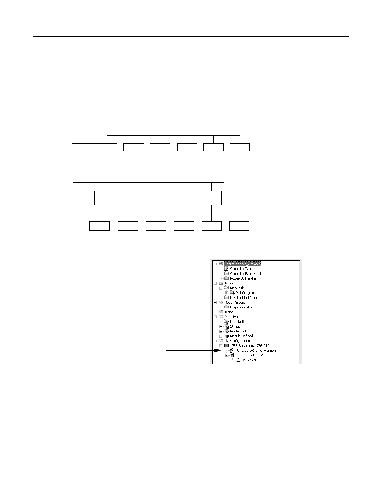
Place, Configure, and Monitor I/O Modules 59
Configure Distributed I/O on
To communicate with the I/O modules over a DeviceNet network,
add the DeviceNet bridge to the I/O Configuration folder of the
a DeviceNet Network
controller. You define a scanlist within the DeviceNet scanner to
communicate data between devices and the controller.
Configuring Distributed I/O on a DeviceNet Network
For a typical distributed I/O network…
Single Network
ScannerController
Several Smaller Distributed Networks (subnets)
Controller
Device
Device Device Device Device
Linking
Device
Device Device Device Device Device
Device
Linking
Device
…you build the I/O configuration in this order
Add the local communication module (bridge).
Additional Resources
For additional information, consult DeviceNet Communication
Modules in Logix5000 Control Systems User Manual, publication
DNET-UM004.
Publication 1756-UM001G-EN-P - January 2007
Page 60

60 Place, Configure, and Monitor I/O Modules
Address I/O Data
I/O information is presented as a set of tags.
• Each tag uses a structure of data. The structure depends on the
specific features of the I/O module.
• The name of the tags is based on the location of the I/O module
in the system.
An I/O address follows this format.
Location :Slot :Type .Member .SubMember .Bit
Where Definition
Location Network location
LOCAL = same chassis or DIN rail as the controller
ADAPTER_NAME = identifies remote communication adapter or bridge module
Slot Slot number of I/O module in its chassis or DIN rail
Type Type of data
I = input
= Optional
O = output
C = configuration
S = status
Member Specific data from the I/O module; depends on what type of data the module can store.
• For a digital module, a Data member usually stores the input or output bit values.
• For an analog module, a Channel member (CH#) usually stores the data for a channel.
SubMember Specific data related to a Member.
Bit Specific point on a digital I/O module; depends on the size of the I/O module (0...31 for a 32-point module)
Publication 1756-UM001G-EN-P - January 2007
Page 61

Place, Configure, and Monitor I/O Modules 61
Add 1756 I/O at Runtime
With RSLogix 5000 programming software, version 16, you:
• can only add 1756 I/O modules to the Controller Organizer at
runtime.
• can remotely add the 1756 I/O modules to the local chassis via
the unscheduled portion of a ControlNet network.
• can remotely add the 1756 I/O modules to the local chassis via
the unscheduled portion of an EtherNet/IP network.
ControlNet I/O Considerations
When you add ControlNet I/O at runtime:
• remember that the ControlNet I/O modules you add can be
added to existing rack-optimized connections or added as direct
connections.
You cannot create new rack-optimized connections when
adding ControlNet I/O modules at runtime.
• disable the Change of State (COS) feature on digital input
modules because it can cause inputs to be sent more quickly
than the RPI.
• dedicate one ControlNet network to I/O communication only.
On the dedicated I/O network, make sure there is:
– no HMI traffic.
– no MSG traffic.
– no programming workstations.
• RPIs faster than 25 ms for unscheduled modules will overload
the 1756-CNB or 1756-CNBR communication module, so:
– use a NUT if 10 ms or more.
– keep the SMAX and UMAX values as small as possible.
• you can add I/O modules until you reach:
– 75% utilization of the 1756-CNB or 1756-CNBR
communication module.
– a utilization increase of 1...4% for each I/O module you add,
depending on the RPI.
– 48 connections on the 1756-CNB or 1756-CNBR
communication module.
– < 350,000 bytes as the remaining unscheduled bandwidth on
the ControlNet network.
Publication 1756-UM001G-EN-P - January 2007
Page 62

62 Place, Configure, and Monitor I/O Modules
EtherNet/IP I/O Considerations
When you add EtherNet/IP I/O at runtime:
• the EtherNet/IP I/O modules you add at runtime use can be:
– added to existing rack-optimized connections.
– added to new rack-optimized connections.
– added as direct connections.
You can create new rack-optimized connections when adding
EtherNet/IP I/O modules at runtime.
• you can add I/O modules until you reach the limits of the
communication module.
Module Type Pulses per
Second, Max
1756-ENBT 4500
1756-ENET,
Series B
810 160 64
Additional Resources
For additional information, consult the EtherNet/IP Performance
Application Guide, publication ENET-AP001.
TCP
Connections,
Max
64
CIP
Connected
Messages,
Max
128
Connected
Bridged
Messages,
Max
128 32
Connected
End Node
Messages,
Max
Unconnected
Messages,
Max
256
Publication 1756-UM001G-EN-P - January 2007
Page 63

Place, Configure, and Monitor I/O Modules 63
Determine When Data Is Updated
Input or Output Data?
Input
Analog or Digital?
Analog
RTS ≤ RPI?
Yes
Data is sent to the backplane
at the RTS.
No
Data is sent to the backplane at
the RTS and RPI.
ControlLogix controllers update date asynchronously with the
execution of logic. Use this flowchart to determine when a producer,
such as a controller, input module, or bridge module, will send data.
Overview - Updating Data
Digital
Output
COS for Any Point on the
Module?
Yes
Analog or Digital?
No
Analog
Remote or Local?
Remote
Digital
Local
Data is sent to the backplane at the RPI
and at the change of a specified point.
• Over a ControlNet network, remote data is sent at the actual packet
interval.
• Over an EtherNet/IP network, remote data is usually sent close to
the RPI.
Data is sent to the backplane at the
RPI.
Data is sent to the backplane at the RPI
and at the end of every task.
Publication 1756-UM001G-EN-P - January 2007
Page 64

64 Place, Configure, and Monitor I/O Modules
Reconfigure an I/O Module
If an I/O module supports reconfiguration, you can reconfigure the
module via:
• RSLogix 5000 programming software.
• a MSG instruction in program logic.
WARNING
Use care when changing the configuration of an I/O module.
You could inadvertently cause the I/O module to operate
incorrectly.
Reconfigure a Module via RSLogix 5000 Programming Software
To reconfigure a module, perform this procedure.
1. In RSLogix 5000 programming software, right-click a module in
the I/O Configuration tree and select Properties.
The Module Properties dialog appears.
2. Reconfigure the I/O module.
3. Click OK.
Publication 1756-UM001G-EN-P - January 2007
Page 65

Place, Configure, and Monitor I/O Modules 65
Reconfigure an I/O Module via a MSG Instruction
Use a MSG instruction of type Module Reconfigure to send new
configuration information to an I/O module. During the
reconfiguration:
• input modules continue to send input data to the controller.
• output modules continue to control their output devices.
To reconfigure an I/O module, perform this procedure.
1. Set the required member of the configuration tag of the module
to the new value.
2. Send a Module Reconfigure message to the module..
EXAMPLE
Reconfigure an I/O module
When reconfigure[5] is on, the MOV instruction sets the high alarm to 60 for the local module in slot 4. The Module
Reconfigure message then sends the new alarm value to the module. The ONS instruction prevents the rung from
sending multiple messages to the module while the reconfigure[5] is on.
Publication 1756-UM001G-EN-P - January 2007
Page 66

66 Place, Configure, and Monitor I/O Modules
Notes:
Publication 1756-UM001G-EN-P - January 2007
Page 67

Develop Applications
Chapter
6
Introduction
This chapter explains how to develop applications.
Topic Page
Manage Tasks 67
DevelopPrograms 68
Organize Tags 72
Select a Programming Language 73
Monitor Controller Status 75
Monitor Connections 76
Select a System Overhead Percentage 79
Additional Resources
For additional general information, consult these publications:
• Logix5000 Controllers Common Procedures Programming
Manual, publication 1756-PM001.
• Logix5000 Controllers Design Considerations Reference Manual,
publication 1756-RM094
Manage Tasks
67 Publication 1756-UM001G-EN-P - January 2007
A Logix5000 controller lets you use multiple tasks to schedule and
prioritize the execution of your programs based on specific criteria.
This multitasking allocates the controller’s processing time among the
different operations in your application.
• The controller executes only one task at a time.
• One task can interrupt another execution and take control.
• In any given task, only one program executes at a time.
Page 68

68 Develop Applications
DevelopPrograms
Control Application
Tas k 1
The controller operating system is a preemptive multitasking system
that is IEC 1131-3 compliant. This environment provides:
• tasks to configure controller execution.
• programs to group data and logic.
• routines to encapsulate executable code written in a single
programming language.
Program Development Overview
Controller Fault Handler
Task 8
Configuration
Status
Program 32
Watchdog
Program 1
Main Routine
Fault Routine
Controller (global) Tags I/O Data System-shared Data
Program (local)
Ta gs
Other Routines
Publication 1756-UM001G-EN-P - January 2007
Page 69

Develop Applications 69
Define Tasks
A task provides scheduling and priority information for a set of one or
more programs. You can configure tasks as continuous, periodic, or
event.
Types of ControlLogix Controller Tasks
Task Execution Task Type Description
All of the time Continuous The continuous task runs in the background. Any CPU time not allocated to other operations (such as
motion, communication, and other tasks) is used to execute the programs in the continuous task.
• The continuous task runs constantly. When the continuous task completes a full scan, it restarts
immediately.
• A project does not require a continuous task. If used, there can be only one continuous task.
• At a set interval,
such as every
100 ms
• Multiple times
within the scan
of your other
logic
Immediately when
an event occurs
Periodic A periodic task performs a function at a specific interval.
• Whenever the time for the periodic task expires, the task interrupts any lower priority tasks,
executes once, and then returns control to where the previous task left off.
• You can configure the time period from 0.1...2000 μs. The default is
10 ms. It is also controller and configuration dependent.
• The performance of a periodic task depends on the type of Logix5000 controller and on the logic in
the task.
Event An event task performs a function only when a specific event (trigger) occurs. The trigger for the event
task can be:
• a consumed tag trigger.
• an EVENT instruction.
• an axis trigger.
• a motion event trigger.
The ControlLogix controller supports up to 32 tasks, only one of
which can be continuous.
A task can have up to 100 separate programs, each with its own
executable routines and program-scoped tags. Once a task is triggered
(activated), all the programs assigned to the task execute in the order
in which they are grouped. Programs can only appear once in the
Controller Organizer and cannot be shared by multiple tasks.
Specify Task Priorities
Each task in the controller has a priority level. The operating system
uses the priority level to determine which task to execute when
multiple tasks are triggered. You can configure periodic tasks to
execute from the lowest priority of 15 up to the highest priority of 1. A
higher priority task will interrupt any lower priority task. The
continuous task has the lowest priority and is always interrupted by a
periodic or event task.
Publication 1756-UM001G-EN-P - January 2007
Page 70

70 Develop Applications
Define Programs
Each program contains program tags, a main executable routine, other
routines, and an optional fault routine. Each task can schedule as
many as 100 programs.
The scheduled programs within a task execute to completion from
first to last. Programs that aren’t attached to any task show up as
unscheduled programs. You must specify (schedule) a program within
a task before the controller can scan the program.
Unscheduled programs within a task are downloaded to the controller
with the entire project. The controller verifies unscheduled programs
but does not execute them.
Define Routines
A routine is a set of logic instructions in a single programming
language, such as Ladder Diagram. Routines provide the executable
code for the project in a controller. A routine is similar to a program
file or subroutine in a PLC or SLC processor.
Each program has a main routine. This is the first routine to execute
when the controller triggers the associated task and calls the
associated program. Use logic, such as the Jump to Subroutine (JSR)
instruction, to call other routines.
You can also specify an optional program fault routine. The controller
executes this routine if it encounters an instruction-execution fault
within any of the routines in the associated program.
Publication 1756-UM001G-EN-P - January 2007
Page 71

Develop Applications 71
Sample Controller Projects
RSLogix 5000 Enterprise programming software includes sample
projects that you can copy and then modify to fit your application.
To obtain a list of sample projects, perform this procedure.
1. In RSlogix 5000 programming software, from the Help menu,
choose Vendor Sample Projects.
2. Scroll down to select the appropriate set of sample projects.
Additional Resources
For more information, consult Logix5000 Controllers Design
Considerations Reference Manual, publication 1756-RM094.
Publication 1756-UM001G-EN-P - January 2007
Page 72

72 Develop Applications
Organize Tags
With a Logix5000 controller, you use a tag (alphanumeric name) to
address data (variables). In Logix5000 controllers, there is no fixed,
numeric format. The tag name itself identifies the data. This lets you:
• organize your data to mirror your machinery.
• document your application as you develop it.
Tag Organization Overview
Analog I/O Device
Integer Value
Storage Bit
Counter
Tim er
Digital I/O Device
When you create a tag, you assign these properties to the tag:
• tag type
• data type
• scope
Publication 1756-UM001G-EN-P - January 2007
Page 73

Develop Applications 73
Select a Programming
The ControlLogix controller supports these programming languages,
both online and offline.
Language
Logix5000 Programming Languages
Required Language Programs
Ladder diagram (LD) Continuous or parallel execution of multiple operations (not sequenced)
Boolean or bit-based operations
Complex logical operations
Message and communication processing
Machine interlocking
Operations that service or maintenance personnel may have to interpret in order to
troubleshoot the machine or process
Function block diagram (FBD) Continuous process and drive control
Loop control
Calculations in circuit flow
Sequential function chart (SFC) High-level management of multiple operations
Repetitive sequence of operations
Batch process
Motion control using structured text
State machine operations
Structured text (ST) Complex mathematical operations
Specialized array or table loop processing
ASCII string handling or protocol processing
Add-On Instructions
With version 16 of RSLogix 5000 programming software, you can
design and configure sets of commonly used instructions to increase
project consistency. Similar to the built-in instructions contained in
Logix5000 controllers, these instructions you create are called Add-On
Instructions. Add-On Instructions reuse common control algorithms.
With them, you can:
• ease maintenance by animating logic for a single instance.
• protect intellectual property with locking instructions.
• reduce documentation development time.
You can use Add-On Instructions across multiple projects. You can
define your instructions, obtain them from somebody else, or copy
them from another project.
Publication 1756-UM001G-EN-P - January 2007
Page 74

74 Develop Applications
Once defined in a project, Add-On Instructions behave similarly to the
built-in instructions in Logix5000 controllers. They appear on the
instruction tool bar for easy access, as do internal RSLogix 5000
software instructions.
Save Time
With Add-On Instructions, you can combine your most commonly
used logic into sets of reusable instructions. You save time when you
create instructions for your projects and then share them with others.
Add-On Instructions increase project consistency since commonly
used algorithms all work in the same manner, regardless of who
implements the project.
Use Standard Editors
You create Add-On Instructions by using one of three RSLogix 5000
software programming editors.
• Standard Ladder
• Function Block Diagram
• Structured Text
Once you have created instructions, you can use them in any RSLogix
5000 editor.
Export Add-On Instructions
You can export Add-On Instructions to other projects as well as copy
and paste them from one project to another. Give each instruction a
unique name so that you don’t accidentally overwrite another
instruction of the same name.
Use Context Views
Context views let you visualize an instruction’s logic for a specific
instant, simplifying online troubleshooting of your Add-On
Instructions. Each instruction contains a revision, a change history,
and an auto-generated help page.
Create Custom Help
Publication 1756-UM001G-EN-P - January 2007
When you create an instruction, you enter information for the
description fields in software dialogs, information that becomes what
is known as Custom Help. Custom Help makes it easier for users to
get the help they need when implementing the instructions.
Page 75

Develop Applications 75
Apply Source Protection
As the creator of Add-On Instructions, you can limit users of your
instructions to read-only access, or you can bar access to the internal
logic or local parameters used by the instructions. This source
protection lets you prevent unwanted changes to your instructions
and protects your intellectual property.
Additional Resources
For additional information, consult the Logix5000 Controllers
Execution Time and Memory Use Reference Manual, publication
1756-RM087.
Monitor Controller Status
The ControlLogix controller uses Get System Value (GSV) and Set
System Value (SSV) instructions to get and set (change) controller
data. The controller stores system data in objects. There is no status
file, as in the PLC-5 processor.
The GSV instruction retrieves the specified information and places it
in the destination. The SSV instruction sets the specified attribute with
data from the source.
When you enter a GSV/SSV instruction, the programming software
displays the valid object classes, object names, and attribute names for
each instruction. For the GSV instruction, you can get values for all the
available attributes. For the SSV instruction, the software displays only
those attributes you are allowed to set.
Some object types appear repeatedly, so you may have to specify the
object name. For example, there can be several tasks in your
application. Each task has its own TASK object that you access by the
task name.
You can access these object classes:
• AXIS
• CONTROLLER
• CONTROLLERDEVICE
• CST
• DF1
• FAULTLOG
• MESSAGE
• MODULE
• MOTIONGROUP
• PROGRAM
• ROUTINE
• SERIALPORT
• TASK
• WALLCLOCKTIME
Publication 1756-UM001G-EN-P - January 2007
Page 76
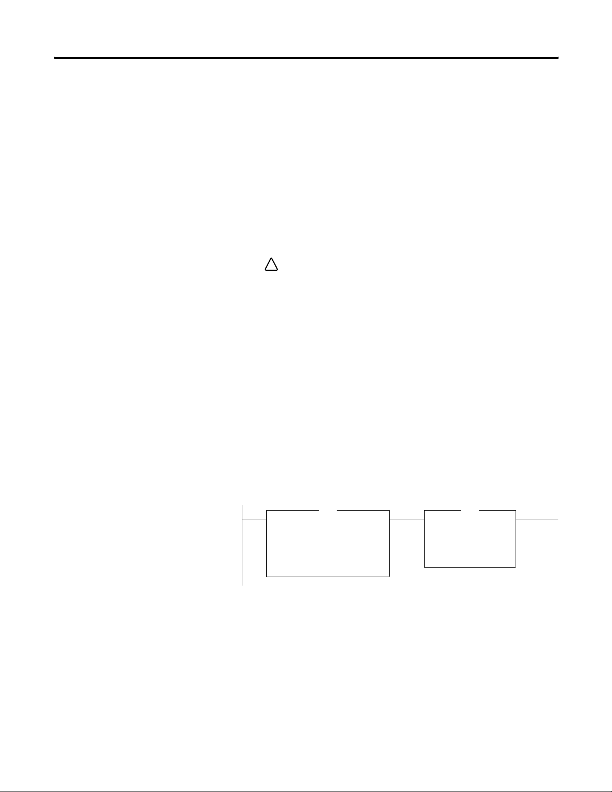
76 Develop Applications
Additional Resources
For additional information, consult the Logix5000 Controllers General
Instructions Reference Manual, publication 1756-RM003.
Monitor Connections
If communication with a device in the I/O configuration of the
controller does not occur for 100 ms or 4 times the RPI, whichever is
less, the communication times out and the controller produces these
warnings.
• The I/O LED on the front of the controller flashes green.
• A
shows over the I/O configuration folder and over the
!
devices that have timed out.
• A module fault code is produced, which you can access via:
– the Module Properties dialog.
– a GSV instruction.
Determine if Communication Has Timed Out with Any Device
If communication times out with at least one device (module) in the
I/O configuration of the controller, the I/O LED on the front of the
controller flashes green.
• The GSV instruction gets the status of the I/O LED and stores it
in the I_O_LED tag.
• If I_O_LED equal 2, the controller has lost communication with
at least one device.
Publication 1756-UM001G-EN-P - January 2007
Get System Value
GSV
CIP Object Class MODULE
CIP Object Name
Attribute Name LedStatus
Dest I_O_LED
EQU
Equal
Source A I_O_LED
Source B 2
where:
I_O_LED is a DINT tag that stores the status of the I/O LED on
the front of the controller.
Page 77

Develop Applications 77
Determine if Communication Has Timed Out with a Specific I/O Module
If communication times out with a device (module) in the I/O
configuration of the controller, the controller produces a fault code for
the module.
• The GSV instruction gets the fault code for Io_Module and stores
it in the Module_Status tag.
• If Module_Status is any value other than 4, the controller is not
communicating with the module.
Publication 1756-UM001G-EN-P - January 2007
Page 78

78 Develop Applications
Interrupt the Execution of Logic and Execute the Fault Handler
To interrupt the execution of logic and execute the fault handler,
perform this procedure.
1. In the Controller Organizer of RSLogix 5000 programming
software, right-click the module and select Properties.
The Module Properties dialog appears.
Publication 1756-UM001G-EN-P - January 2007
2. Click the Connection tab.
3. Select the Major Fault If Connection Fails While in Run Mode
check box.
4. Develop a routine for the Controller Fault Handler.
Page 79

Develop Applications 79
Select a System Overhead Percentage
The Controller Properties dialog lets you specify a percentage for the
system overhead, or time slice. The system overhead time slice
specifies the percentage of controller time, excluding the time for
periodic and event tasks, devoted to communication and background
functions.
To select a system overhead percentage slice, perform this procedure.
1. In the Controller Organizer of RSLogix 5000 programming
software, right-click the controller and select Properties.
The Controller Properties dialog appears.
2. Click the Advanced tab.
3. Specify the system overhead settings.
System overhead functions include:
• communication with programming and HMI devices (such as
RSLogix 5000 programming software).
• responding to messages.
• transmission of messages.
Publication 1756-UM001G-EN-P - January 2007
Page 80

80 Develop Applications
4. Click OK.
The controller performs system overhead functions for up to 1 ms at a
time. If the controller completes the overhead functions in less than
1 ms, it resumes the continuous task.
As the system overhead percentage increases, time allocated to
executing the continuous task decreases. If there is no communication
for the controller to manage, the controller uses the communication
time to execute the continuous task. While increasing the system
overhead percentage does increase communication performance, it
also increases the amount of time it takes to execute a continuous
task, increasing overall scan time.
Ratio between the Continuous Task and System Overhead Functions
Time Slice Continuous Task Length Max Overhead Function Time
10% 9 ms 1 ms
20% 4 ms 1 ms
33% 2 ms 1 ms
50% 1 ms 1 ms
Periodic
System Overhead
Continuous Task
At a time slice of 10%, system overhead interrupts the continuous task
every 9 ms (of continuous task time).
Legend:
Task executes.
Task is interrupted (suspended).
1 ms 1 ms
9 ms 9 ms
0 5 10 15 20 25
Elapsed Time (ms)
Publication 1756-UM001G-EN-P - January 2007
Page 81

Periodic Task
System Overhead
Continuous Task
System Overhead
Continuous Task
Develop Applications 81
The interruption of a periodic task increases the elapsed time (clock
time) between the execution of system overhead functions.
1 ms 1 ms 1 ms 1 ms 1 ms
1 ms 1 ms
9 ms of Continuous Task Time 9 ms of Continuous Task Time
0 5 10 15 20 25
Elapsed Time (ms)
If you use the default time slice of 20%, the system overhead
interrupts the continuous task every 4 ms.
1 ms 1 ms 1 ms 1 ms 1 ms
4 ms 4 ms 4 ms 4 ms 4 ms
5 10152025
Elapsed Time (ms)
System Overhead
Continuous Task
Periodic Task
System Overhead
Continuous Task
If you increase the time slice to 50%, the system overhead interrupts
the continuous task every millisecond.
1 ms
1 ms
5 10152025
Elapsed Time (ms)
If the controller only contains periodic tasks, the system overhead
time slice value has no effect. System overhead runs whenever a
periodic task is not running.
5 10152025
Elapsed Time (ms)
Publication 1756-UM001G-EN-P - January 2007
Page 82

82 Develop Applications
Notes:
Publication 1756-UM001G-EN-P - January 2007
Page 83

Configure PhaseManager
Chapter
7
Introduction
This chapter explains how to configure PhaseManager.
Within RSLogix 5000 programming software, PhaseManager provides a
state model for your equipment.
Topic Page
PhaseManager Overview 83
State Model Overview 85
Compare PhaseManager to Other State Models 87
Minimum System Requirements 88
Equipment Phase Instructions 88
Additional Resources
For more information consult, PhaseManager User Manual,
publication LOGIX-UM001.
PhaseManager Overview
Term Description
Equipment phase • As with a program, an equipment phase is run in a task and is given a set of routines and tags.
• Unlike a program, an equipment phase runs by a state model and lets you do one activity.
State model • A state model divides the operating cycle of your equipment into a series of states. Each state is an instant in the
operation of the equipment, the actions, or conditions of the equipment at a given time.
• The state model of an equipment phase resembles that of the S88 and PackML state models.
State machine An equipment phase includes an embedded state machine that:
• calls the main routine (state routine) for an acting state.
• manages the transitions between states with minimal coding.
• makes sure that the equipment goes from state to state along an allowable path.
PHASE tag When you add an equipment phase, RSLogix 5000 programming software makes a tag for the equipment phase. The
tag uses the PHASE data type.
83 Publication 1756-UM001G-EN-P - January 2007
PhaseManager lets you add equipment phases to your controller. An
equipment phase helps you lay out your code in sections that are
easier to write, find, follow, and change.
PhaseManager Terms
Page 84

84 Configure PhaseManager
Controller
Controller Tags
Tasks
MainTask
PhaseManager Overview
A PHASE tag gives you the status of an equipment phase.
An equipment phase directs one activity of your equipment.
Add Water Phase
Mix Phase
Drain Phase
Space Parts Phase
MainProgram
My Equipment Program
A state model divides the activity into a series of states.
Running State Routine
How to add
water
Equipment phase instructions control the transitions between states and
handle faults.
PSC POVR PCLF PRNP PATT
PCMD PFL PXRQ PPD PDET
Other code controls the specific actions of your equipment.
Water Feed
Conveyor Enable Axes
Publication 1756-UM001G-EN-P - January 2007
Page 85

Configure PhaseManager 85
State Model Overview
Start
Idle
Resetting
Reset
Running
Complete
A state model defines what your equipment does under different
conditions, such as run, hold, and stop.
PhaseManager States
State Description
Acting Does something or several things for a certain time or until certain conditions
are met. An acting state runs once or repeatedly.
Waiting Shows that certain conditions are met and the equipment is waiting for the
signal to go to the next state.
PhaseManager State Transitions
Hold
Holding
Hold
Restarting
Stop
Stopping
Held
Restart
Abort
Abort
Aborting
Your equipment can go from any state in
the box to the stopping or aborting state.
Acting
Acting states represent the things your
equipment does at a given time.
Waiting
Reset
Waiting states represent the condition of your
equipment when it is between acting states.
Stopped Aborted
With a state model, you define the behavior of your equipment.
PhaseManager State Models
State Question to be asked
Stopped What happens when you turn on power?
Resetting How does the equipment get ready to run?
Idle How do you tell that the equipment is ready to run?
Running What does the equipment do to make product?
Holding How does the equipment temporarily stop making product without making
scrap?
Held How do you tell if the equipment is safely holding?
Restarting How does the equipment resume production after holding?
Complete How do you tell when the equipment is done with what it had to do?
Stopping What happens during a normal shutdown?
Aborting How does the equipment shut down if a fault or failure occurs?
Aborted How do you tell if the equipment is safely shut down?
Publication 1756-UM001G-EN-P - January 2007
Page 86
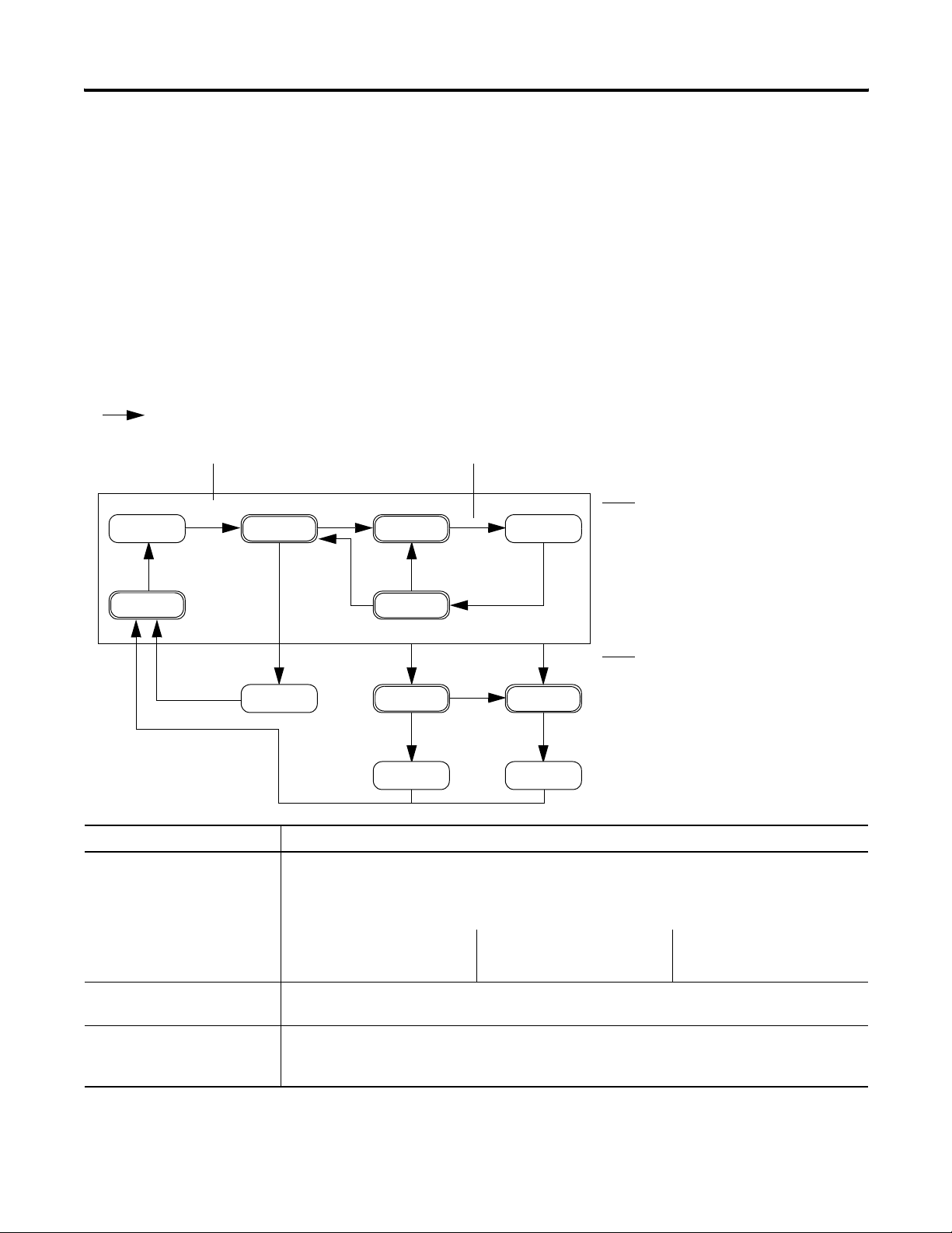
86 Configure PhaseManager
= Transition
Command Done — No command. Use PSC instruction instead.
How Equipment Changes States
The state model’s arrows show the states through which your
equipment progresses.
• Each arrow is called a transition.
• A state model lets the equipment make only certain transitions.
This restriction standardizes the equipment’s behavior so that
other equipment using the same model will behave the same
way.
PhaseManager Transition Commands
Your equipment can go from any state in
the box to the stopping or aborting state.
Fault (specific use of the abort
command)
Idle
Resetting
Reset
Start
Running
Complete
Reset
Hold
Holding
Hold
Restart
Restarting
Stop
Abort
Stopping
Stopped Aborted
Held
Aborting
Abort
Type of Transition Description
Command A command tells the equipment to do something. For example, the operator pushes the start button to
begin production and the stop button to halt production.
PhaseManager uses these commands:
Reset Stop Restart
Start Hold Abort
Done Equipment goes to a waiting state when it is finished with what it is doing. You do not give the
equipment a command. Instead, you set up your code to signal when the equipment is finished.
Fault A fault tells you that something out of the ordinary has happened. You set up your code to look for
faults and take action if it finds any. If you want to shut down your equipment as quickly as possible
when it detects a fault, set up your code to look for that fault and give the abort command if it finds it.
Publication 1756-UM001G-EN-P - January 2007
Page 87

Current Equipment Phase
Configure PhaseManager 87
Manually Change States
With RSLogix 5000 programming software, you can manually change
an equipment phase.
To manually change a PhaseManager state, perform this procedure.
1. Take ownership of the equipment phase.
2. Give a command.
Compare PhaseManager to Other State Models
You can compare PhaseManager state models to other state models.
S88 PackML PhaseManager
Idle Starting ⇒ Ready Resetting ⇒ Idle
Running ⇒ Complete Producing Running ⇒ Complete
Pausing ⇒ Paused Standby Subroutines or breakpoints
Holding ⇒ Held Holding ⇒ Held Holding ⇒ Held
Restarting None Restarting
Stopping ⇒ Stopped Stopping ⇒ Stopped Stopping ⇒ Stopped
Aborting ⇒ Aborted Aborting ⇒ Aborted Aborting ⇒ Aborted
Publication 1756-UM001G-EN-P - January 2007
Page 88

88 Configure PhaseManager
Minimum System Requirements
Equipment Phase Instructions
To develop PhaseManager programs, you need:
• a ControlLogix controller, firmware revision 16.0 or later.
• a communication path to the controller.
• RSLogix 5000 software, version 16.0 or later.
To enable PhaseManager support, you need the full or professional
editions of RSLogix 5000 programming software or RSLogix 5000 with
PhaseManager software (9324-RLDPMENE).
The controller supports several equipment-phase ladder diagram (LD)
and structured text (ST) instructions.
PhaseManager Instructions
Instruction Instruction Function
PSC Signal a phase that the state routine is complete and to
proceed to the next state.
PCMD Change the state or substate of a phase.
PFL Signal a failure for a phase.
PCLF Clear the failure code of a phase.
PXRQ Initiate communication with RSBizWare Batch software.
PRNP Clear the NewInputParameters bit of a phase.
PPD Set up breakpoints within the logic of a phase.
PATT Take ownership of a phase to either:
• prevent another program or RSBizWare Batch software
from commanding a phase.
• make sure another program or RSBizWare Batch software
does not already own a phase.
PDET Relinquish ownership of a phase.
POVR Override a command.
Publication 1756-UM001G-EN-P - January 2007
Page 89

Develop Motion Applications
Chapter
8
Introduction
RSLogix 5000 Programming
Software
Integrated
Axis
Configuration
Programming
Motion
This chapter explains how to configure a motion control program.
Topic Page
Make the Controller the CST Master 90
Add the Motion Modules 91
Add SERCOS Interface Drives 93
Set Up Each SERCOS Interface Module 95
Add the Motion Group 97
Add Your Axes 100
Set Up Each Axis 101
Check the Wiring of Each Drive 104
Tune Each Axis 106
Obtain Axis Information 108
Program Motion Control 109
Overview of Motion Control Configuration
ControlLogix Controller
Program Execution
Motion Planner
Position Velocity
1756 Analog Motion Module
Drive
Position Velocity
Motor
Feedback
Drive
Position Velocity
Motor
Feedback
1756 SERCOS Interface Module
SERCOS Interface Drive
Position Velocity
Motor
Feedback
89 Publication 1756-UM001G-EN-P - January 2007
Page 90
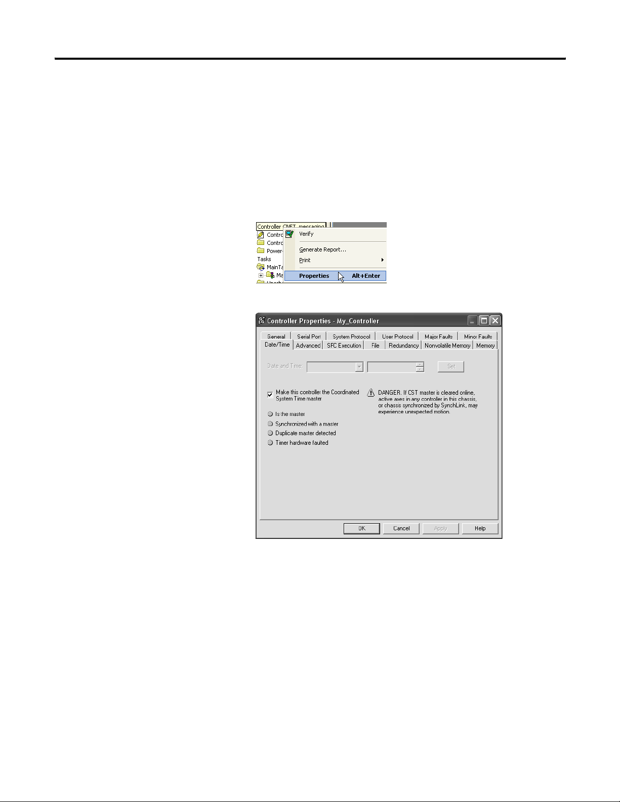
90 Develop Motion Applications
Make the Controller the CST Master
You must make one module in the chassis the master clock for motion
control. This module is called the coordinated system time (CST)
master. Motion modules set their clocks to the master.
In most cases, make the controller the CST master.
To make the controller the CST master, perform this procedure.
1. In RSLogix 5000 programming software, right-click the controller
and select Properties.
The Controller Properties dialog appears.
Publication 1756-UM001G-EN-P - January 2007
2. Click the Date/Time tab.
3. Select the Make this controller the Coordinated System Time
master check box.
4. Click OK.
Multiple Controllers in the Chassis
If you have more than one controller in the chassis, designate one
controller as the CST master. You cannot have more than one CST
master for the chassis.
Page 91

Develop Motion Applications 91
Add the Motion Modules
Each ControlLogix controller controls up to 16 motion modules.
IMPORTANT
For your motion modules, use the firmware revision that
matches that of your controller. See the release notes for your
controller’s firmware revision.
Required Motion Modules
Used with Equipment Feedback Type Required Motion Module
Rockwell Automation
SERCOS interface drives
Analog command signal Quadrature feedback 1756-M02AE
⇒ ⇒ ⇒ ⇒ 1756-M03SE (3 axes)
1756-M08SE (8 axes)
1756-M16SE (16 axes)
1756-L60M03SE (3 axes)
LDT feedback 1756-HYD02
SSI feedback 1756-M02AS
To add motion modules, perform this procedure.
1. In the Controller Organizer of RSLogix 5000 programming
software, right-click your module and select New Module.
The Select Module dialog appears.
2. Double-click Motion.
3. Select the motion module you want to add.
Publication 1756-UM001G-EN-P - January 2007
Page 92

92 Develop Motion Applications
4. Click OK.
The New Module dialog appears.
5. In the Name box, type the name of the new module
6. In the Slot box, enter the slot the new module will occupy.
7. Leave Open Module Properties unchecked.
8. Click OK.
Additional Information
For additional information, consult these publications:
• Motion Analyzer Selection Guide, publication PST-SG003
• ControlLogix Selection Guide, publication 1756-SG001
Publication 1756-UM001G-EN-P - January 2007
Page 93

Develop Motion Applications 93
Add SERCOS Interface Drives
With the addition of SERCOS interface modules to a controller’s I/O
configuration, you can use RSLogix 5000 programming software to set
up the modules.
To add SERCOS interface modules, perform this procedure.
1. In the I/O configuration tree in RSLogix 5000 programming
software, right-click the SERCOS network and select New
Module.
The Select Module dialog appears.
2. Double-click Other.
3. Select your drive.
Choose from these SERCOS interface drives:
• 1394
• Kinetix 6000
• Ultra3000
• 8720MC
4. Click OK.
Publication 1756-UM001G-EN-P - January 2007
Page 94

94 Develop Motion Applications
The New Module dialog appears.
5. In the Name box, type the name of the new drive.
6. In the Node box, select the node number of the drive in the
SERCOS ring.
7. Click OK.
Additional Resources
For additional information, consult these publications:
• Motion Analyzer Selection Guide, publication PST-SG003
• ControlLogix Selection Guide, publication 1756-SG001
• Logix5000 Motion Module User Manual, publication 1756-UM006
Publication 1756-UM001G-EN-P - January 2007
Page 95

Develop Motion Applications 95
Set Up Each SERCOS Interface Module
To set the data rate and cycle time for each SERCOS interface module
in your project, perform this procedure.
1. In the I/O configuration tree in RSLogix 5000 programming
software, right-click your module and select Properties.
The Module Properties dialog appears.
2. Click the SERCOS Interface tab.
3. From the Data Rate pull-down menu, choose Auto Detect.
Publication 1756-UM001G-EN-P - January 2007
Page 96

96 Develop Motion Applications
4. From the Cycle Time pull-down menu, choose the cycle time.
Baud Rate
of Drive
4 MB 1 or 2 Kinetix 6000 0.5 ms
8 MB 1…4 Kinetix 6000 0.5 ms
Number of Drives
on Ring
3 or 4 1 ms
5…8 2 ms
9…16 Not possible. You must
1…4 Not Kinetix 6000 1 ms
5…8 2 ms
9…16 Not possible. You must
5…8 1 ms
9…16 2 ms
1…8 Not Kinetix 6000 1 ms
9…16 2 ms
Type of Drive Cycle Time
5. Click OK.
have 2 motion modules.
have 2 motion modules.
Publication 1756-UM001G-EN-P - January 2007
Page 97

Develop Motion Applications 97
Add the Motion Group
Motion Planner Part of the controller that takes care of position and velocity information for your axes
Coarse Update Period How often the motion planner runs. When the motion planner runs, it interrupts all other
Motion Planner
Scans of your code,
System overhead,
and so on
IMPORTANT
0 ms 10 ms
In this example, the coarse update period = 10 ms. Every 10 ms the controller stops scanning your code
and whatever else it is doing and runs the motion planner.
You can add a motion group to set up the motion planner.
tasks regardless of their priority.
20 ms 30 ms 40 ms
Add only one motion group for the project. RSLogix 5000 software does not let you
add more than one motion group.
To add a motion group to set up the motion planner, perform this
procedure.
1. Choose your coarse update period.
IMPORTANT
The coarse update period is the interval between updating
your axes’ positions and scanning your code.
a. Set the coarse update period to 10 ms.
b. Leave at least half the controller’s time for the scanning of all
your code.
c. Set the coarse update period to a multiple of the cycle time of
the motion module.
Example: If the cycle time is 2 ms, set the coarse update
period to 8 ms, 10 ms, 12 ms, and so on.
2. In RSLogix 5000 programming software, right-click Motion
Groups and select New Motion Group.
Publication 1756-UM001G-EN-P - January 2007
Page 98

98 Develop Motion Applications
The New Tag dialog appears.
3. In the Name box, enter the tag name.
4. From the Data Type pull-down menu, choose
MOTION_GROUP.
5. Click OK.
The Motion Group Wizard dialog appears.
Publication 1756-UM001G-EN-P - January 2007
6. Click Next.
Page 99

Develop Motion Applications 99
The Motion Group Wizard Attributes dialog appears.
7. In the Coarse Update Period box, enter the intervals at which
you want to run your motion planner.
8. Click Finish.
Publication 1756-UM001G-EN-P - January 2007
Page 100

100 Develop Motion Applications
Add Your Axes
To add an axis for each of your drives, perform this procedure.
1. Decide which data type to use.
Motion Module Data Type
• 1756-M03SE
• 1756-M08SE
• 1756-M16SE
• 1756-L60M03SE
1756-M08SEG AXIS_GENERIC_DRIVE
AXIS_SERVO_DRIVE
2. In Motion Groups within RSLogix 5000 programming software,
right-click My Motion Group and select New Axis and then the
type of axis you want to add.
Analog
SERCOS Interface
The New Tag dialog appears.
3. In the Name box, enter the name of your new axis.
4. Leave Open AXIS_SERVO_DRIVE Configuration unchecked.
5. Click OK.
Publication 1756-UM001G-EN-P - January 2007
 Loading...