

Page 1

ControlLogix Digital I/O Modules
Catalog Numbers 1756-IA8D, 1756-IA16, 1756-IA16I, 1756-IA32, 1756-IB16, 1756-IB16D, 1756-IB16I, 1756-IB16IF, 1756-IB32,
1756-IC16, 1756-IG16, 1756-IH16I, 1756-IM16I, 1756-IN16, 1756-IV16, 1756-IV32, 1756-OA8, 1756-OA8D, 1756-OA8E,
1756-OA16, 1756-OA16I, 1756-OB8, 1756-OB8EI, 1756-OB8I, 1756-OB16D, 1756-OB16E, 1756-OB16I, 1756-OB16IEF,
1756-OB16IEFS, 1756-OB16IS, 1756-OB32, 1756-OC8, 1756-OG16, 1756-OH8I, 1756-ON8, 1756-OV16E, 1756-OV32E,
1756-OW16I, 1756-OX81
User Manual
Page 2
Important User Information
Solid-state equipment has operational characteristics differing from those of electromechanical equipment. Safety
Guidelines for the Application, Installation and Maintenance of Solid State Controls (publication SGI-1.1
available from
your local Rockwell Automation® sales office or online at http://www.rockwellautomation.com/literature/
) describes some
important differences between solid-state equipment and hard-wired electromechanical devices. Because of this difference,
and also because of the wide variety of uses for solid-state equipment, all persons responsible for applying this equipment
must satisfy themselves that each intended application of this equipment is acceptable.
In no event will Rockwell Automation, Inc. be responsible or liable for indirect or consequential damages resulting from the
use or application of this equipment.
The examples and diagrams in this manual are included solely for illustrative purposes. Because of the many variables and
requirements associated with any particular installation, Rockwell Automation, Inc. cannot assume responsibility or
liability for actual use based on the examples and diagrams.
No patent liability is assumed by Rockwell Automation, Inc. with respect to use of information, circuits, equipment, or
software described in this manual.
Reproduction of the contents of this manual, in whole or in part, without written permission of Rockwell Automation,
Inc., is prohibited.
Throughout this manual, when necessary, we use notes to make you aware of safety considerations.
Allen-Bradley, ControlLogix, ControlLogix-XT, DH+, Data Highway Plus, Integrated Architecture, Rockwell Software, Rockwell Automation, RS Logix, RSNetWorx, and TechConnect are trademarks of Rockwe ll
Automation, Inc.
Trademarks not belonging to Rockwell Automation are property of their respective companies.
WARNING: Identifies information about practices or circumstances that can cause an explosion in a hazardous environment,
which may lead to personal injury or death, property damage, or economic loss.
ATTENTION: Identifies information about practices or circumstances that can lead to personal injury or death, property
damage, or economic loss. Attentions help you identify a hazard, avoid a hazard, and recognize the consequence.
SHOCK HAZARD: Labels may be on or inside the equipment, for example, a drive or motor, to alert people that dangerous
voltage may be present.
BURN HAZARD: Labels may be on or inside the equipment, for example, a drive or motor, to alert people that surfaces may
reach dangerous temperatures.
IMPORTANT
Identifies information that is critical for successful application and understanding of the product.
Page 3

Rockwell Automation Publication 1756-UM058G-EN-P - November 2012 3
Summary of Changes
This manual contains new and updated information. Changes throughout this
revision are marked by change bars, as shown to the right of this paragraph.
Top ic Pag e
Studio 5000™ Logix Designer application is the rebranding of RSLogix™ 5000 software 11
Added the 1756-OB16IEFS module to the list of I/O modules 15
Added content to describe when output data is sent to the 1756-OB16IEFS module in motion
applications
33
Added the 1756-OB16IEFS module to the CIP Sync time section 48
Added the 1756-OB16IEFS module to sections about electronic fusing, diagnostic latching, and
time-scheduled output control
54, 58, 63
Added the 1756-OB16IEFS module to the list of fast I/O modules 83
Added software version requirements for the 1756-OB16IEFS module 84
Added the 1756-OB16IEFS module to the table of connection formats 133
Added the wiring diagram for the 1756-OB16IEFS module 165
Added status indicators for the 1756-OB16IEFS module 179
Added tag definitions for the 1756-OB16IEFS module 202
Added the 1756-OB16IEFS module to the list of IFMs 245
Page 4

4 Rockwell Automation Publication 1756-UM058G-EN-P - November 2012
Summary of Changes
Notes:
Page 5

Rockwell Automation Publication 1756-UM058G-EN-P - November 2012 5
Table of Contents
Preface
Studio 5000 Environment . . . . . . . . . . . . . . . . . . . . . . . . . . . . . . . . . . . . . . . . 11
Additional Resources . . . . . . . . . . . . . . . . . . . . . . . . . . . . . . . . . . . . . . . . . . . . . 12
Chapter 1
What Are ControlLogix
Digital I/O Modules?
Available Features . . . . . . . . . . . . . . . . . . . . . . . . . . . . . . . . . . . . . . . . . . . . . . . . 13
I/O Modules in the ControlLogix System . . . . . . . . . . . . . . . . . . . . . . . . . . 14
Module Identification and Status Information. . . . . . . . . . . . . . . . . . . . . . 17
Chapter 2
Digital I/O Operation
in the ControlLogix System
Ownership . . . . . . . . . . . . . . . . . . . . . . . . . . . . . . . . . . . . . . . . . . . . . . . . . . . . . . 20
Use RSNetWorx and RSLogix 5000 Software . . . . . . . . . . . . . . . . . . . . . . 20
Internal Module Operation . . . . . . . . . . . . . . . . . . . . . . . . . . . . . . . . . . . . . . . 21
Input Modules . . . . . . . . . . . . . . . . . . . . . . . . . . . . . . . . . . . . . . . . . . . . . . . 21
Output Modules . . . . . . . . . . . . . . . . . . . . . . . . . . . . . . . . . . . . . . . . . . . . . 22
Connections. . . . . . . . . . . . . . . . . . . . . . . . . . . . . . . . . . . . . . . . . . . . . . . . . . . . . 23
Direct Connections . . . . . . . . . . . . . . . . . . . . . . . . . . . . . . . . . . . . . . . . . . 24
Rack-optimized Connections. . . . . . . . . . . . . . . . . . . . . . . . . . . . . . . . . . 24
Suggestions for Rack-optimized Connections . . . . . . . . . . . . . . . . . . . 26
Input Module Operation . . . . . . . . . . . . . . . . . . . . . . . . . . . . . . . . . . . . . . . . . 26
Input Modules in a Local Chassis. . . . . . . . . . . . . . . . . . . . . . . . . . . . . . . . . . 27
RPI . . . . . . . . . . . . . . . . . . . . . . . . . . . . . . . . . . . . . . . . . . . . . . . . . . . . . . . . . 27
COS . . . . . . . . . . . . . . . . . . . . . . . . . . . . . . . . . . . . . . . . . . . . . . . . . . . . . . . . 27
Trigger Event Tasks . . . . . . . . . . . . . . . . . . . . . . . . . . . . . . . . . . . . . . . . . . 28
Input Modules in a Remote Chassis. . . . . . . . . . . . . . . . . . . . . . . . . . . . . . . . 28
Remote Input Modules Connected via the ControlNet Network. 29
Remote Input Modules Connected via the EtherNet/IP Network 30
Output Module Operation . . . . . . . . . . . . . . . . . . . . . . . . . . . . . . . . . . . . . . . 31
Output Modules in a Local Chassis . . . . . . . . . . . . . . . . . . . . . . . . . . . . . . . . 31
Output Modules in a Remote Chassis. . . . . . . . . . . . . . . . . . . . . . . . . . . . . . 32
Remote Output Modules Connected via the ControlNet Network. 32
Remote Output Modules Connected via the EtherNet/IP Network 33
Listen-only Mode . . . . . . . . . . . . . . . . . . . . . . . . . . . . . . . . . . . . . . . . . . . . . . . . 34
Multiple Owner-Controllers of Input Modules . . . . . . . . . . . . . . . . . . . . . 34
Configuration Changes in an Input Module with Multiple Owners . . 35
Chapter 3
Common Module Features
Input Module Compatibility. . . . . . . . . . . . . . . . . . . . . . . . . . . . . . . . . . . . . . 37
Output Module Compatibility . . . . . . . . . . . . . . . . . . . . . . . . . . . . . . . . . . . . 38
Common Features . . . . . . . . . . . . . . . . . . . . . . . . . . . . . . . . . . . . . . . . . . . . . . . 39
Removal and Insertion Under Power. . . . . . . . . . . . . . . . . . . . . . . . . . . 39
Module Fault Reporting . . . . . . . . . . . . . . . . . . . . . . . . . . . . . . . . . . . . . . 39
Software Configurable . . . . . . . . . . . . . . . . . . . . . . . . . . . . . . . . . . . . . . . . 40
Electronic Keying . . . . . . . . . . . . . . . . . . . . . . . . . . . . . . . . . . . . . . . . . . . . 40
Module Inhibiting. . . . . . . . . . . . . . . . . . . . . . . . . . . . . . . . . . . . . . . . . . . . 46
Page 6

6 Rockwell Automation Publication 1756-UM058G-EN-P - November 2012
Table of Contents
Use the System Clock to Timestamp Inputs and Schedule Outputs. 47
Producer/Consumer Communication. . . . . . . . . . . . . . . . . . . . . . . . . . 50
Status Indicator Information . . . . . . . . . . . . . . . . . . . . . . . . . . . . . . . . . . 50
Common Features Specific to Input Modules. . . . . . . . . . . . . . . . . . . . . . . 50
Data Transfer on Either Cyclic Time or Change of State . . . . . . . . . 51
Set RPI . . . . . . . . . . . . . . . . . . . . . . . . . . . . . . . . . . . . . . . . . . . . . . . . . . . . . . 51
Enable Change of State. . . . . . . . . . . . . . . . . . . . . . . . . . . . . . . . . . . . . . . . 52
Software Configurable Filter Times . . . . . . . . . . . . . . . . . . . . . . . . . . . . 53
Isolated and Nonisolated Varieties of Input Modules . . . . . . . . . . . . 53
Multiple Input Point Densities . . . . . . . . . . . . . . . . . . . . . . . . . . . . . . . . 54
Common Features Specific to Output Modules . . . . . . . . . . . . . . . . . . . . . 54
Configurable Point-level Output States. . . . . . . . . . . . . . . . . . . . . . . . . 55
Output Data Echo . . . . . . . . . . . . . . . . . . . . . . . . . . . . . . . . . . . . . . . . . . . . 56
Isolated and Nonisolated Varieties of Output Modules . . . . . . . . . . 56
Multiple Output Point Densities. . . . . . . . . . . . . . . . . . . . . . . . . . . . . . . 57
Electronic Fusing . . . . . . . . . . . . . . . . . . . . . . . . . . . . . . . . . . . . . . . . . . . . . 57
Field Power Loss Detection. . . . . . . . . . . . . . . . . . . . . . . . . . . . . . . . . . . . 60
Diagnostic Latch of Information . . . . . . . . . . . . . . . . . . . . . . . . . . . . . . . 61
Time-scheduled Output Control . . . . . . . . . . . . . . . . . . . . . . . . . . . . . . 63
Fault and Status Reporting between Input Modules and Controllers. . 64
Fault and Status Reporting between Output Modules and Controllers 65
Chapter 4
Diagnostic Module Features
Diagnostic Input Module Compatibility . . . . . . . . . . . . . . . . . . . . . . . . . . . 67
Diagnostic Output Module Compatibility. . . . . . . . . . . . . . . . . . . . . . . . . . 68
Diagnostic Features. . . . . . . . . . . . . . . . . . . . . . . . . . . . . . . . . . . . . . . . . . . . . . . 68
Diagnostic Latch of Information . . . . . . . . . . . . . . . . . . . . . . . . . . . . . . . 68
Diagnostic Timestamp . . . . . . . . . . . . . . . . . . . . . . . . . . . . . . . . . . . . . . . . 69
8-Point AC/16-Point DC . . . . . . . . . . . . . . . . . . . . . . . . . . . . . . . . . . . . . 70
Point-level Fault Reporting . . . . . . . . . . . . . . . . . . . . . . . . . . . . . . . . . . . . 70
Features Specific to Diagnostic Input Modules. . . . . . . . . . . . . . . . . . . . . . 71
Diagnostic Change of State for Input Modules . . . . . . . . . . . . . . . . . . 71
Open Wire Detection. . . . . . . . . . . . . . . . . . . . . . . . . . . . . . . . . . . . . . . . . 73
Field Power Loss Detection. . . . . . . . . . . . . . . . . . . . . . . . . . . . . . . . . . . . 74
Features Specific to Diagnostic Output Modules . . . . . . . . . . . . . . . . . . . . 75
Field Wiring Options . . . . . . . . . . . . . . . . . . . . . . . . . . . . . . . . . . . . . . . . . 75
No Load Detection . . . . . . . . . . . . . . . . . . . . . . . . . . . . . . . . . . . . . . . . . . . 75
Field-side Output Verification . . . . . . . . . . . . . . . . . . . . . . . . . . . . . . . . . 76
Pulse Test . . . . . . . . . . . . . . . . . . . . . . . . . . . . . . . . . . . . . . . . . . . . . . . . . . . . 78
Diagnostic Change of State for Output Modules . . . . . . . . . . . . . . . . 79
Fault and Status Reporting between Input Modules and Controllers. . 79
Fault and Status Reporting between Output Modules and Controllers 81
Page 7

Rockwell Automation Publication 1756-UM058G-EN-P - November 2012 7
Table of Contents
Chapter 5
Fast Module Features
Fast Input Module Compatibility . . . . . . . . . . . . . . . . . . . . . . . . . . . . . . . . . 83
Fast Output Module Compatibility. . . . . . . . . . . . . . . . . . . . . . . . . . . . . . . . 84
Fast Features. . . . . . . . . . . . . . . . . . . . . . . . . . . . . . . . . . . . . . . . . . . . . . . . . . . . . 84
Response Time. . . . . . . . . . . . . . . . . . . . . . . . . . . . . . . . . . . . . . . . . . . . . . . 85
Features Specific to Fast Input Modules. . . . . . . . . . . . . . . . . . . . . . . . . . . . 85
Pulse Capture . . . . . . . . . . . . . . . . . . . . . . . . . . . . . . . . . . . . . . . . . . . . . . . . 86
Per Point Timestamping and Change of State. . . . . . . . . . . . . . . . . . . 87
Software Configurable Filter Times . . . . . . . . . . . . . . . . . . . . . . . . . . . . 90
Dedicated Connection for Event Tasks. . . . . . . . . . . . . . . . . . . . . . . . . 93
Features Specific to Fast Output Modules . . . . . . . . . . . . . . . . . . . . . . . . . . 95
Programmable Fault State Delays . . . . . . . . . . . . . . . . . . . . . . . . . . . . . . 95
Pulse Width Modulation. . . . . . . . . . . . . . . . . . . . . . . . . . . . . . . . . . . . . . 97
Fault and Status Reporting between Input Modules and Controllers 106
Fault and Status Reporting between Output Modules and Controllers 107
Chapter 6
Install ControlLogix I/O Modules
Install the Module. . . . . . . . . . . . . . . . . . . . . . . . . . . . . . . . . . . . . . . . . . . . . . . 111
Key the Removable Terminal Block. . . . . . . . . . . . . . . . . . . . . . . . . . . . . . . 113
Connect the Wires . . . . . . . . . . . . . . . . . . . . . . . . . . . . . . . . . . . . . . . . . . . . . . 114
RTB Types . . . . . . . . . . . . . . . . . . . . . . . . . . . . . . . . . . . . . . . . . . . . . . . . . 116
RTB Wiring Recommendations . . . . . . . . . . . . . . . . . . . . . . . . . . . . . . 118
Assemble the Removable Terminal Block and Housing. . . . . . . . . . . . . 119
Choose Extended-depth Housing . . . . . . . . . . . . . . . . . . . . . . . . . . . . . . . . 120
Cabinet Size Considerations with Extended-depth Housing . . . . 121
Install the Removable Terminal Block . . . . . . . . . . . . . . . . . . . . . . . . . . . . 122
Remove the Removable Terminal Block. . . . . . . . . . . . . . . . . . . . . . . . . . . 123
Remove the Module from the Chassis. . . . . . . . . . . . . . . . . . . . . . . . . . . . . 125
Chapter 7
Configure ControlLogix
Digital I/O Modules
Configuration Process Overview . . . . . . . . . . . . . . . . . . . . . . . . . . . . . . . . . 128
Create a New Module . . . . . . . . . . . . . . . . . . . . . . . . . . . . . . . . . . . . . . . . . . . 129
Communication or Connection Formats. . . . . . . . . . . . . . . . . . . . . . 131
Edit the Configuration . . . . . . . . . . . . . . . . . . . . . . . . . . . . . . . . . . . . . . . . . . 134
Connection Properties . . . . . . . . . . . . . . . . . . . . . . . . . . . . . . . . . . . . . . . . . . 135
View and Change Module Tags . . . . . . . . . . . . . . . . . . . . . . . . . . . . . . . . . . 136
Chapter 8
Wiring Diagrams
1756-IA8D . . . . . . . . . . . . . . . . . . . . . . . . . . . . . . . . . . . . . . . . . . . . . . . . . 139
1756-IA16. . . . . . . . . . . . . . . . . . . . . . . . . . . . . . . . . . . . . . . . . . . . . . . . . . 139
1756-IA16I . . . . . . . . . . . . . . . . . . . . . . . . . . . . . . . . . . . . . . . . . . . . . . . . . 140
1756-IA32. . . . . . . . . . . . . . . . . . . . . . . . . . . . . . . . . . . . . . . . . . . . . . . . . . 141
1756-IB16 . . . . . . . . . . . . . . . . . . . . . . . . . . . . . . . . . . . . . . . . . . . . . . . . . . 142
1756-IB16D . . . . . . . . . . . . . . . . . . . . . . . . . . . . . . . . . . . . . . . . . . . . . . . . 143
1756-IB16I . . . . . . . . . . . . . . . . . . . . . . . . . . . . . . . . . . . . . . . . . . . . . . . . . 144
1756-IB16IF . . . . . . . . . . . . . . . . . . . . . . . . . . . . . . . . . . . . . . . . . . . . . . . . 145
Page 8

8 Rockwell Automation Publication 1756-UM058G-EN-P - November 2012
Table of Contents
1756-IB32 . . . . . . . . . . . . . . . . . . . . . . . . . . . . . . . . . . . . . . . . . . . . . . . . . . 146
1756-IC16 . . . . . . . . . . . . . . . . . . . . . . . . . . . . . . . . . . . . . . . . . . . . . . . . . . 147
1756-IG16 . . . . . . . . . . . . . . . . . . . . . . . . . . . . . . . . . . . . . . . . . . . . . . . . . . 148
1756-IH16I . . . . . . . . . . . . . . . . . . . . . . . . . . . . . . . . . . . . . . . . . . . . . . . . . 149
1756-IM16I. . . . . . . . . . . . . . . . . . . . . . . . . . . . . . . . . . . . . . . . . . . . . . . . . 150
1756-IN16. . . . . . . . . . . . . . . . . . . . . . . . . . . . . . . . . . . . . . . . . . . . . . . . . . 150
1756-IV16 . . . . . . . . . . . . . . . . . . . . . . . . . . . . . . . . . . . . . . . . . . . . . . . . . . 151
1756-IV32 . . . . . . . . . . . . . . . . . . . . . . . . . . . . . . . . . . . . . . . . . . . . . . . . . . 152
1756-OA8 . . . . . . . . . . . . . . . . . . . . . . . . . . . . . . . . . . . . . . . . . . . . . . . . . . 153
1756-OA8D . . . . . . . . . . . . . . . . . . . . . . . . . . . . . . . . . . . . . . . . . . . . . . . . 154
1756-OA8E. . . . . . . . . . . . . . . . . . . . . . . . . . . . . . . . . . . . . . . . . . . . . . . . . 155
1756-OA16 . . . . . . . . . . . . . . . . . . . . . . . . . . . . . . . . . . . . . . . . . . . . . . . . . 156
1756-OA16I . . . . . . . . . . . . . . . . . . . . . . . . . . . . . . . . . . . . . . . . . . . . . . . . 157
1756-OB8 . . . . . . . . . . . . . . . . . . . . . . . . . . . . . . . . . . . . . . . . . . . . . . . . . . 158
1756-OB8EI . . . . . . . . . . . . . . . . . . . . . . . . . . . . . . . . . . . . . . . . . . . . . . . . 159
1756-OB8I. . . . . . . . . . . . . . . . . . . . . . . . . . . . . . . . . . . . . . . . . . . . . . . . . . 160
1756-OB16D . . . . . . . . . . . . . . . . . . . . . . . . . . . . . . . . . . . . . . . . . . . . . . . 161
1756-OB16E. . . . . . . . . . . . . . . . . . . . . . . . . . . . . . . . . . . . . . . . . . . . . . . . 162
1756-OB16I . . . . . . . . . . . . . . . . . . . . . . . . . . . . . . . . . . . . . . . . . . . . . . . . 163
1756-OB16IEF. . . . . . . . . . . . . . . . . . . . . . . . . . . . . . . . . . . . . . . . . . . . . . 164
1756-OB16IEFS . . . . . . . . . . . . . . . . . . . . . . . . . . . . . . . . . . . . . . . . . . . . 165
1756-OB16IS . . . . . . . . . . . . . . . . . . . . . . . . . . . . . . . . . . . . . . . . . . . . . . . 166
1756-OB32 . . . . . . . . . . . . . . . . . . . . . . . . . . . . . . . . . . . . . . . . . . . . . . . . . 167
1756-OC8 . . . . . . . . . . . . . . . . . . . . . . . . . . . . . . . . . . . . . . . . . . . . . . . . . . 168
1756-OG16 . . . . . . . . . . . . . . . . . . . . . . . . . . . . . . . . . . . . . . . . . . . . . . . . . 169
1756-OH8I . . . . . . . . . . . . . . . . . . . . . . . . . . . . . . . . . . . . . . . . . . . . . . . . . 170
1756-ON8 . . . . . . . . . . . . . . . . . . . . . . . . . . . . . . . . . . . . . . . . . . . . . . . . . . 171
1756-OV16E. . . . . . . . . . . . . . . . . . . . . . . . . . . . . . . . . . . . . . . . . . . . . . . . 172
1756-OV32E. . . . . . . . . . . . . . . . . . . . . . . . . . . . . . . . . . . . . . . . . . . . . . . . 173
1756-OW16I . . . . . . . . . . . . . . . . . . . . . . . . . . . . . . . . . . . . . . . . . . . . . . . 174
1756-OX8I . . . . . . . . . . . . . . . . . . . . . . . . . . . . . . . . . . . . . . . . . . . . . . . . . 175
Appendix A
Troubleshoot Your Module
Status Indicators for Input Modules. . . . . . . . . . . . . . . . . . . . . . . . . . . . . . . 177
Status Indicators for Output Modules. . . . . . . . . . . . . . . . . . . . . . . . . . . . . 178
Use RSLogix 5000 Software for Troubleshooting . . . . . . . . . . . . . . . . . . 180
Fault Type Determination. . . . . . . . . . . . . . . . . . . . . . . . . . . . . . . . . . . . 181
Appendix B
Tag Definitions
Standard and Diagnostic Input Module Tags . . . . . . . . . . . . . . . . . . . . . . 183
Standard and Diagnostic Output Module Tags . . . . . . . . . . . . . . . . . . . . 186
Fast Input Module Tags. . . . . . . . . . . . . . . . . . . . . . . . . . . . . . . . . . . . . . . . . . 189
Fast Output Module Tags. . . . . . . . . . . . . . . . . . . . . . . . . . . . . . . . . . . . . . . . 194
1756-OB16IEF Module. . . . . . . . . . . . . . . . . . . . . . . . . . . . . . . . . . . . . . 194
1756-OB16IEFS Module. . . . . . . . . . . . . . . . . . . . . . . . . . . . . . . . . . . . . 202
Array Data Structures. . . . . . . . . . . . . . . . . . . . . . . . . . . . . . . . . . . . . . . . . . . . 211
Page 9

Rockwell Automation Publication 1756-UM058G-EN-P - November 2012 9
Table of Contents
Appendix C
Use Ladder Logic To Perform
Run Time Services and
Reconfiguration
Using Message Instructions . . . . . . . . . . . . . . . . . . . . . . . . . . . . . . . . . . . . . . 213
Processing Real-time Control and Module Services . . . . . . . . . . . . . . . . 214
One Service Performed Per Instruction . . . . . . . . . . . . . . . . . . . . . . . . . . . 214
Create a New Tag . . . . . . . . . . . . . . . . . . . . . . . . . . . . . . . . . . . . . . . . . . . . . . . 214
Enter Message Configuration. . . . . . . . . . . . . . . . . . . . . . . . . . . . . . . . . 217
Configuration Tab . . . . . . . . . . . . . . . . . . . . . . . . . . . . . . . . . . . . . . . . . . 218
Communication Tab . . . . . . . . . . . . . . . . . . . . . . . . . . . . . . . . . . . . . . . . 221
Use Timestamped Inputs and Scheduled Outputs
for Standard and Diagnostic I/O Modules. . . . . . . . . . . . . . . . . . . . . 222
Use Timestamped Inputs and Scheduled Outputs
for Fast I/O Modules . . . . . . . . . . . . . . . . . . . . . . . . . . . . . . . . . . . . . . . . 224
Reset a Fuse, Perform Pulse Test and Reset Latched Diagnostics. 227
Perform a WHO to Retrieve Module Identification and Status. . 228
Review of Tags in Ladder Logic. . . . . . . . . . . . . . . . . . . . . . . . . . . . . . . 231
Appendix D
Choose a Correct Power Supply
. . . . . . . . . . . . . . . . . . . . . . . . . . . . . . . . . . . . . . . . . . . . . . . . . . . . . . . . . . . . . . . . .233
Appendix E
Motor Starters for Digital I/O Modules
Determine the Maximum Number of Motor Starters. . . . . . . . . . . 236
Appendix F
Major Revision Upgrades
If Using a Compatible or Disabled Keying I/O Configuration . . . . . . 238
If Using an Exact Match Keying Configuration . . . . . . . . . . . . . . . . . . . . 238
Appendix G
1492 IFMs for Digital I/O Modules
Cable Overview . . . . . . . . . . . . . . . . . . . . . . . . . . . . . . . . . . . . . . . . . . . . . . . . . 239
Appendix H
History of Changes
1756-UM058F-EN-P, April 2012 . . . . . . . . . . . . . . . . . . . . . . . . . . . . . . . . 249
1756-UM058E-EN-P, August 2010 . . . . . . . . . . . . . . . . . . . . . . . . . . . . . . 250
Glossary
Index
Page 10

10 Rockwell Automation Publication 1756-UM058G-EN-P - November 2012
Table of Contents
Notes:
Page 11

Rockwell Automation Publication 1756-UM058G-EN-P - November 2012 11
Preface
This manual describes how to install, configure, and troubleshoot your
ControlLogix® digital I/O modules. There is also a complete listing of digital
input and output modules, including specifications and wiring diagrams. You
must be able to program and operate a ControlLogix controller to efficiently use
your digital I/O module.
Studio 5000 Environment
The Studio 5000™ Engineering and Design Environment combines engineering
and design elements into a common environment. The first element in the
Studio 5000 environment is the Logix Designer application. The Logix Designer
application is the rebranding of RSLogix™ 5000 software and will continue to be
the product to program Logix5000™ controllers for discrete, process, batch,
motion, safety, and drive-based solutions.
The Studio 5000 environment is the foundation for the future of Rockwell
Automation® engineering design tools and capabilities. It is the one place for
design engineers to develop all the elements of their control system.
Page 12

12 Rockwell Automation Publication 1756-UM058G-EN-P - November 2012
Preface
Additional Resources
These documents contain additional information concerning related products
from Rockwell Automation.
You can view or download publications at
http://www.rockwellautomation.com/literature/
. To order paper copies of
technical documentation, contact your local Allen-Bradley distributor or
Rockwell Automation sales representative.
Resource Description
1756 ControlLogix I/O Modules Specifications
Technical Data, publication 1756-TD002
Provides specifications for ControlLogix I/O modules.
ControlLogix High-speed Counter Module User Manual,
publication 1756-UM007
Describes how to install, configure, and troubleshoot the
1756-HSC counter module.
ControlLogix Low-speed Counter Module User Manual,
publication 1756-UM536
Describes how to install, configure, and troubleshoot the
1756-LSC8XIB8I counter module.
ControlLo gix Peer I/O Control Appl ication Techni que,
publication 1756-AT016
Describes typical peer control applications and provides
details about how to configure I/O modules for peer
control operation.
Position-based Output Control with the MAOC Instruction,
publication 1756-AT017
Describes typical applications for using scheduled output
modules with the Motion Axis Output Cam (MAOC)
instruction.
Integrated Architecture and CIP Sync Configuration
Application Technique, publication IA-AT003
Describes how to configure CIP Sync with Integrated
Architecture™ products and applications.
ControlLogix Chassis and Power Supplies Installation
Instructions, publication 1756-IN005
Describes how to install and troubleshoot standard and
ControlLogix-XT versions of the 1756 chassis and power
supplies, including redundant power supplies.
ControlLogix Analog I/O Modules User Manual,
publication 1756-UM009
Describes how to install, configure, and troubleshoot
ControlLogix analog I/O modules.
ControlLogix Data Highway Plus-Remote I/O
Communication Interface Module User Manual,
publication 1756-UM514
Describes how to configure and operate the ControlLogix
DH+™ / Remote I/O module.
ControlLogix-XT Data Highway Plus-Remote I/O
Communication Interface Module Installation
Instructions, publication 1756-IN638
Describes how to install, configure, and troubleshoot the
ControlLogix-XT Data Highway Plus™-Remote I/O
Communication Interface module.
ControlLogix System User Manual,
publication 1756 UM001
Describes how to install, configure, program, and operate
a ControlLogix system.
Industrial Automation Wiring and Grounding Guidelines,
publication 1770-4.1
Provides general guidelines for installing a Rockwell
Automation industrial system.
Product Certifications website, http://ab.com
Provides declarations of conformity, certificates, and other
certification details.
Page 13

Rockwell Automation Publication 1756-UM058G-EN-P - November 2012 13
Chapter 1
What Are ControlLogix Digital I/O Modules?
ControlLogix® digital I/O modules are input and output modules that provide
On/Off detection and actuation. By using the producer/consumer network
model, digital I/O modules can produce information when needed while
providing additional system functions.
Available Features
The table lists several features available on ControlLogix digital I/O modules.
Top ic Pag e
Available Features 13
I/O Modules in the ControlLogix System 14
Module Identification and Status Info rmation 17
Feature Description
Removal and Insertion Under Power (RIUP) You can remove and insert modules and removable terminal blocks
(RTB) while power is applied.
Producer/consumer communication This communication method is an intelligent data exchange between
modules and other system devices in which each module produces
data without first being polled.
System time stamp of data A 64-bit system clock places a time stamp on the transfer of data
between the module and its owner-controller.
Module-level fault reporting and field-side
diagnostic detection
Fault and diagnostic detection capabilities to help you effec tively and
efficiently use your module and troubleshoot your application.
Agency Certification Class 1, Division 2 agency certification for any applic ation that
requires approval.
Page 14

14 Rockwell Automation Publication 1756-UM058G-EN-P - November 2012
Chapter 1 What Are ControlLogix Digital I/O Modules?
I/O Modules in the
ControlLogix System
ControlLogix modules mount in a ControlLogix chassis and require either a
removable terminal block (RTB) or a Bulletin 1492 wiring interface module
(IFM)
(1)
to connect all field-side wiring.
Before you install and use your module, you must do the following:
• Install and ground a 1756 chassis and power supply. To install these
products, refer to the publications listed in Additional Resources
on
page 12.
• Order and receive an RTB or IFM and its components for your
application.
(1) The ControlLogix system has been agency certified using only the ControlLogix RTB catalog numbers 1756-TBCH, 1756-T BNH,
1756-TBSH, and 1756-TBS6H. Any application that requires agency certification of the ControlLogix system using other wiring
termination methods may require application-specific approval by the certifying agenc y.
IMPORTANT
RTBs and IFMs are not included with your module purchase. See page 116 for
RTBs and page 239
for IFMs.
Table 1 - ControlLogix Digital I/O Modules
Cat. No. Description Page
1756-IA8D 79…132V AC 8-point diagnostic input module 139
1756-IA16 74…132V AC 16-point input module 139
1756-IA16I 79…132V AC 16-point isolated input module 140
1756-IA32 74…132V AC 32-point input module 141
1756-IB16 10…31.2V DC 16-point input module 142
1756-IB16D 10…30V DC diagnostic input module 143
1756-IB16I 10…30V DC 16-point, isolated input module 144
1756-IB16IF 10…30V DC,16-point, isolated, fast peer control input module 145
1756-IB32 10…31.2V DC 32-point input module 146
1756-IC16 30…60V DC 16-point input module 147
1756-IG16 Transitor-transitor logic (TTL) input module 148
1756-IH16I 90…146V DC 16-point isolated input module 149
1756-IM16I 159…265V AC 16-point isolated input module 150
1756-IN16 10…30V AC 16-point input module 150
1756-IV16 10…30V DC 16-point sourcing current input module 151
1756-IV32 10…30V DC 32-point sourcing current input module 152
1756-OA8 74…265V AC 8-point output module
153
1756-OA8D 74…132V AC 8-point diagnostic output module 154
1756-OA8E 74…132V AC 8-point electronically-fused output module 155
1756-OA16 74... 265V AC 16-point output module 156
1756-OA16I 74…265V AC 16-point isolated output module 157
1756-OB8 10…30V DC 8-point output module 158
1756-OB8EI 10…30V DC 8-point electronically-fused, isolated output module 159
1756-OB8I 10…30V DC 8-point isolated output module 160
1756-OB16D 19.2…30V DC 16-point diagnostic output module 161
Page 15

Rockwell Automation Publication 1756-UM058G-EN-P - November 2012 15
What Are ControlLogix Digital I/O Modules? Chapter 1
1756-OB16E 10…31.2V DC 16-point electronically-fused output module 162
1756-OB16I 10…30V DC 16-point isolated output module 163
1756-OB16IEF 10…30V DC,16-point, isolated, fast peer control output module 164
1756-OB16IEFS 10…30V DC, 16-point, isolated, fast, scheduled per point output module 165
1756-OB16IS 10…30V DC scheduled, isolated output module 166
1756-OB32 10…31.2V DC 32-point output module 167
1756-OC8 30…60V DC 8-point output module 168
1756-OG16 Transitor-transitor logic (TTL) output module 169
1756-OH81 90…146V DC 8-point isolated output module 170
1756-ON8 10…30V AC 8-point output module 171
1756-OV16E 10…30V DC 16-point electronically-fused, sinking current output module 172
1756-OV32E 10…30V DC 32-point electronically-fused, sinking current output module 173
1756-OW16I 10…265V, 5-150V DC 16-point isolated contact module 174
1756-OX8I 10…265V, 5-150V DC 8-point isolated contact module 175
Table 1 - ControlLogix Digital I/O Modules (continued)
Cat. No. Description Page
Page 16
16 Rockwell Automation Publication 1756-UM058G-EN-P - November 2012
Chapter 1 What Are ControlLogix Digital I/O Modules?
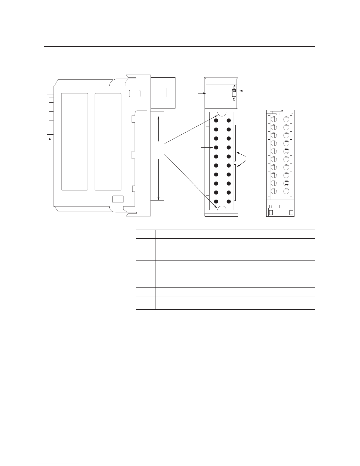
Figure 1 - Parts Illustration
40200-M
DC OUTPUT
ST
O
K
01234567
3
5
Removable Terminal Block
6
4
2
1
Item Description
1 Backplane Connector—Interface for the ControlLogix system that connects the module to the
backplane.
2 Top and bottom guides—Guides provide assistance in seating the RTB or IFM onto the module.
3 Status indicators—Indicators display the status of communication, module health, and input/output
devices. Indicators help in troubleshooting anomalies.
4 Connector pins—Input/output, power, and grounding connections are made to the module through
these pins with the use of an RTB or IFM.
5 Locking tab—The locking tab anchors the RTB or IFM on the module, maintaining wiring connections.
6 Slots for keying—Mechanically keys the RTB to prevent making the wrong wire connections to your
module.
Page 17

Rockwell Automation Publication 1756-UM058G-EN-P - November 2012 17
What Are ControlLogix Digital I/O Modules? Chapter 1
Module Identification and
Status Information
Each ControlLogix I/O module maintains specific identification information
that separates it from all other modules. This information assists you in tracking
all the components of your system.
For example, you can track module identification information to know which
modules are located in any ControlLogix chassis at any time. While retrieving
module identity, you can also retrieve module status.
Item Description
Product type Module’s product type, such as digital I/O or analog I/O
Product code Module’s catalog number
Major revision Module’s major revision number
Minor revision Module’s minor revision number
Status Module’s statu s, including these items:
• Controller ownership
• Whether the module has been configured
• Device-specific status, such as the following:
– Self-test
– Update in progress
– Communications fault
– Not owned (outputs in Program mode)
– Internal fault (needs update)
– Run mode
– Program mode (outputs only)
• Minor recoverable fault
• Minor unrecoverable fault
• Major recoverable fault
• Major unrecoverable fault
Vendor Module’s manufacturer vendor, such as Allen-Bradley
Serial number Module’s serial number
Length of ASCII text string Number of characters in module’s text string
ASCII text string Module’s ASCII text string description
IMPORTANT
You must perform a WHO service to retrieve this information. For more
information, refer to page 228
.
Page 18

18 Rockwell Automation Publication 1756-UM058G-EN-P - November 2012
Chapter 1 What Are ControlLogix Digital I/O Modules?
Notes:
Page 19

Rockwell Automation Publication 1756-UM058G-EN-P - November 2012 19
Chapter 2
Digital I/O Operation in the ControlLogix System
I/O modules are the interface between controllers and field devices in a
ControlLogix system. Digital I/O modules transfer data to devices that require
just one bit to be represented (0 or 1). For example, a switch is open or closed, or
a light is on or off.
Top ic Pa ge
Ownership 20
Use RSNetWorx and RSLogix 5000 Software 20
Internal Module Operation 21
Connec tions 23
Input Module Operation 26
Input Modules in a Local Chassis 27
Input Modules in a Remote Chassis 28
Output Module Operation 31
Output Modules in a Local Chassis 31
Output Modules in a Remote Chassis 32
Listen-only Mode 34
Multiple Owner-Controllers of Input Modules 34
Configuration Changes in an Input Module with Multiple Owners 35
Page 20

20 Rockwell Automation Publication 1756-UM058G-EN-P - November 2012
Chapter 2 Digital I/O Operation in the ControlLogix System
Ownership
I/O modules in a ControlLogix system can be owned by an RSLogix™ 5000
controller. An owner-controller fulfills these functions:
• Stores configuration data for every module that it owns
• Sends I/O modules configuration data to define module behavior and
begin module operation with the control system
• Resides in a local or remote chassis in regard to the I/O module’s position
Each ControlLogix I/O module must continuously maintain communication
with its owner-controller to operate normally.
Typically, each module in the system will have only one owner-controller. Input
modules can have more than one owner-controller. Output modules, however,
are limited to a single owner-controller.
For more information about using multiple owner-controllers, see Configuration
Changes in an Input Module with Multiple Owners on page 35.
Use RSNetWorx and
RSLogix 5000 Software
The I/O configuration within RSLogix 5000 software generates the
configuration data for each I/O module in the control system, including modules
in a remote chassis. A remote chassis contains the I/O module but not the
module’s owner-controller. A remote chassis can be connected to the controller
via an EtherNet/IP network or a scheduled connection on the
ControlNet network.
Configuration data from RSLogix 5000 software is transferred to the controller
during the program download and subsequently transferred to I/O modules. The
I/O modules in the local or remote chassis are ready to run as soon as the
configuration data has been downloaded. However, to enable scheduled
connections to I/O modules on the ControlNet network, you must schedule the
network by using RSNetWorx™ for ControlNet software.
RSNetWorx software transfers configuration data to I/O modules on a scheduled
ControlNet network and establishes a network update time (NUT) for the
ControlNet network that is compliant with the desired communication options
specified for each module during configuration.
Anytime a controller references a scheduled connection to I/O modules on a
scheduled ControlNet network, you must run RSNetWorx software to configure
the ControlNet network.
Page 21

Rockwell Automation Publication 1756-UM058G-EN-P - November 2012 21
Digital I/O Operation in the ControlLogix System Chapter 2
Refer to the following general steps when configuring I/O modules.
1. Configure all I/O modules for a given controller by using
RSLogix 5000 software and download that information to the controller.
2. If the I/O configuration data references a scheduled connection to a
module in a remote chassis connected via the ControlNet network, run
RSNetWorx for ControlNet software to schedule the network.
3. After running RSNetWorx software, perform an online save of the
RSLogix 5000 project to make sure the configuration information that
RSNetWorx software sends to the controller is saved.
Internal Module Operation
ControlLogix I/O modules experience signal propagation delays that must be
accounted for during operation. Some of these delays are user-configurable, and
some are inherent to the module hardware.
For example, there is a small delay, typically less than 1 ms, between when a signal
is applied at the RTB of a ControlLogix input module and when a signal is sent
to the system over the backplane. This time reflects a filter time of 0 ms for a DC
input.
This section offers an explanation of the time limitations with ControlLogix I/O
modules.
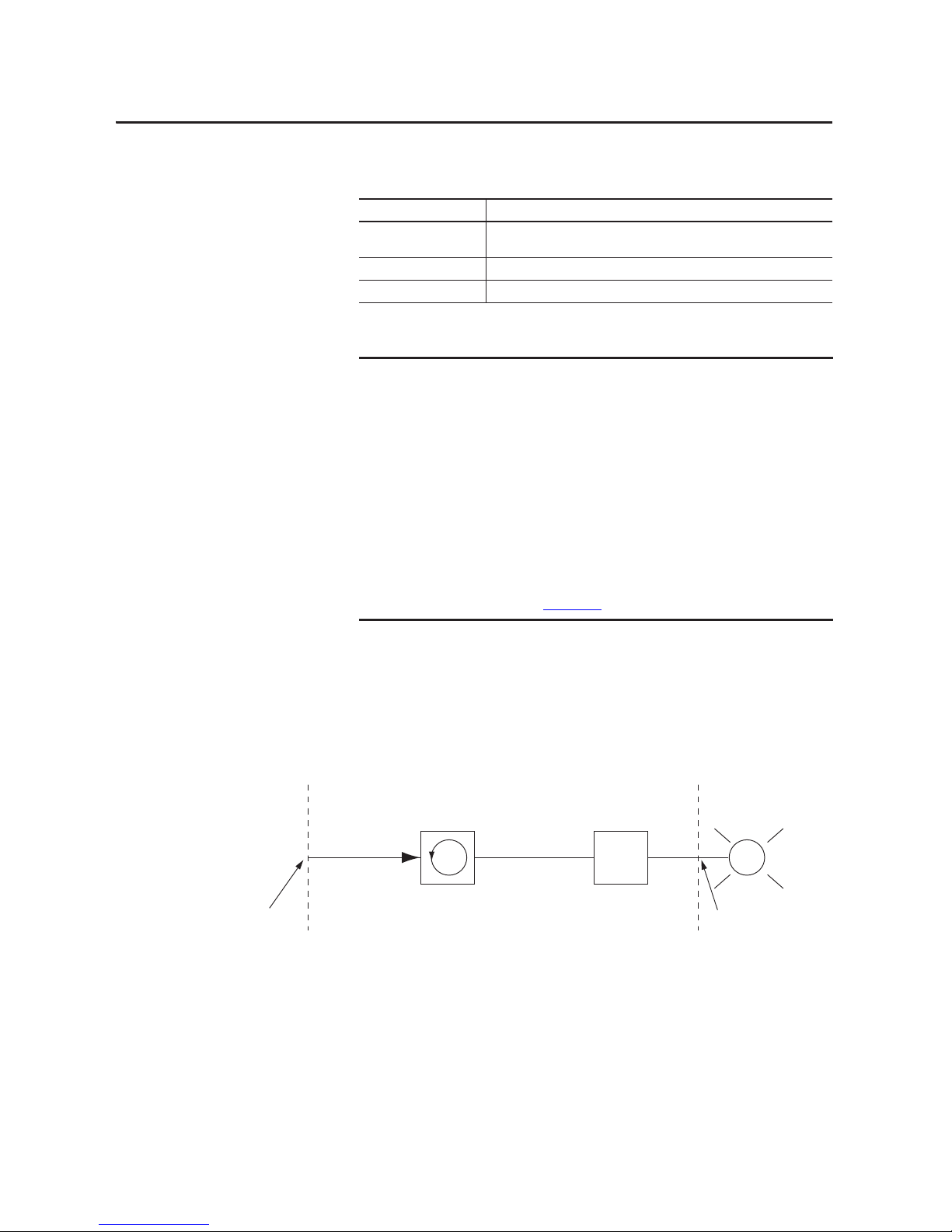
Input Modules
As shown in the illustration below, ControlLogix input modules receive a signal
at the RTB and process it internally through hardware, filters, and an ASIC scan
before sending a signal to the backplane via the requested packet interval (RPI) or
at a Change of State (COS) occurrence. The RPI is a configured interval of time
that determines when a module’s data is sent to the controller.
IMPORTANT
You must run RSNetWorx for ControlNet software whenever a new I/O module
is added to a scheduled ControlNet chassis. When a module is permanently
removed from a remote chassis, we recommend that you run RSNetWorx for
ControlNet software to reschedule the network and optimize the allocation of
network bandwidth.
42701
Hardware Delay
Filter Delay
ASIC Delay
Signal Applied
at the RTB
Signal Sent to
the Backplane
Page 22
22 Rockwell Automation Publication 1756-UM058G-EN-P - November 2012
Chapter 2 Digital I/O Operation in the ControlLogix System
The table defines some of the delay factors that affect the signal propagation on
an I/O module.
Output Modules
ControlLogix output modules receive a signal from the controller and process it
internally via hardware and an ASIC scan before sending a signal to the output
device via the RTB.
Delay Description
Hardware How the module is configured and the variance between the type of modules affects
how the signal is processed.
Filter User configuration varies between modules, thus affecting the signal propagation.
ASIC ASIC scan = 200 µs.
EXAMPLE
A typical delay time can be estimated despite the number of factors that might
contribute. For example, if you are turning on a 1756-IB16 module at 24V DC in
25 °C (77 °F) conditions, the signal propagation delay is affected by these
factors:
• Hardware delay to energize the input (typically 290 µs on the
1756-IB16 module)
• User-configurable filter time of 0, 1, or 2 ms
• ASIC scan of 200 µs
In the worst case scenario with a filter time of 0 ms, the 1756-IB16 module has
a 490 µs signal propagation delay.
These times are not guaranteed. For nominal and maximum delay times for
each module, see the 1756 ControlLogix I/O Modules Specifications Technical
Data, publication 1756-TD002
.
Hardware DelayASIC Delay
42702
Signal Sent from
RTB Output Point
Signal Received
from Controller
Page 23

Rockwell Automation Publication 1756-UM058G-EN-P - November 2012 23
Digital I/O Operation in the ControlLogix System Chapter 2
The table defines some of the delay factors that affect the signal propagation on
an I/O module.
Connections
With ControlLogix I/O modules, a connection is the data transfer link between
a controller and an I/O module. A connection can be one of these types:
• Direct
• Rack-optimized
The table lists the advantages and disadvantages of each connection type.
Delay Description
Hardware How the module is configured and the variance between the type of modules affects
how the signal is processed.
ASIC ASIC scan = 200 µs.
EXAMPLE
A typical delay time can be estimated despite the number of factors that might
contribute. For example, if you are turning on a 1756-OB16E module at 24V DC
in 25 °C (77 °F) conditions, the signal propagation delay is affected by these
factors:
• Hardware delay to energize the input (typically 70 µs on the
1756-OB16E module)
• ASIC scan of 200 µs
In the worst case scenario with a filter time of 0 ms, the 1756-OB16E module
has a 270 µs signal propagation delay.
These times are not guaranteed. See Chapter 8
for nominal and maximum
delay times for each module.
Connection Type Advantages Dis advantages
Direct All input and data echo information is
transferred, including diagnostic
information and fusing data.
With more data transferring over the
network, your system does not operate as
efficiently as with rack connections.
Rack-optimized Connection usage is economized. The
owner-controller has a single RPI value for
each connection.
Input and data echo information is limited
to general faults and data.
Page 24

24 Rockwell Automation Publication 1756-UM058G-EN-P - November 2012
Chapter 2 Digital I/O Operation in the ControlLogix System
Direct Connections
A direct connection is a real-time data transfer link between the controller and
the device that occupies the slot that the configuration data references. When
module configuration data is downloaded to an owner-controller, the controller
attempts to establish a direct connection to each of the modules referenced by the
data.
If a controller has configuration data referencing a slot in the control system, the
controller periodically checks for the presence of a device there. When a device’s
presence is detected there, the controller automatically sends the configuration
data.
If the data is appropriate to the module found in the slot, a connection is made
and operation begins. If the configuration data is not appropriate, the data is
rejected and an error message appears in the software. In this case, the
configuration data can be inappropriate for any of a number of reasons. For
example, a module’s configuration data may be appropriate except for a mismatch
in electronic keying that prevents normal operation.
The controller maintains and monitors its connection with a module. Any break
in the connection causes the controller to set fault status bits in the data area
associated with the module. Breaks in the connection can be caused by a module
fault or the removal of the module from the chassis while under power.
RSLogix 5000 software monitors fault status bits to annunciate module failures.
Rack-optimized Connections
When a digital I/O module is located in a remote chassis with respect to its
owner-controller, you can choose Rack Optimization or Listen-only Rack
Optimization during module configuration. The option you choose depends on
the communication module configuration. If the communication module uses
Listen-only Rack Optimization, then the I/O module must also use Listen-only
Rack Optimization.
A rack-optimized connection economizes bandwidth between owner-controllers
and digital I/O modules in the remote chassis. Rather than having several direct
connections with individual RPI values, an owner-controller has a single rack
connection with a single RPI value. That RPI value accommodates all digital I/O
modules in the remote chassis.
Page 25
Rockwell Automation Publication 1756-UM058G-EN-P - November 2012 25
Digital I/O Operation in the ControlLogix System Chapter 2
The input, or data echo, information is limited to general faults and data. No
additional status, such as diagnostic information, is available.
The illustration below shows how a rack-optimized connection eliminates the
need for three separate connections. The owner-controller in the local chassis
communicates with all the I/O modules in the remote chassis but uses only one
connection. The ControlNet communication module sends data from the
modules simultaneously at the RPI.
Figure 2 - Rack-optimized Connection
IMPORTANT
Because rack-optimized connections are applicable only in applications that
use a remote chassis, you must configure the communication format , as
described in Chapter 7
, for both the remote I/O module and the remote
1756-CNB module or EtherNet/IP module.
Make sure you configure both modules for rack optimization. If you choose a
different communication format for each module, the controller makes two
connections to the same chassis (one for each format) and the same data
travels across the ControlNet network.
If you use rack optimization for both modules, you preserve bandwidth and
configure your system to operate more efficiently.
IMPORTANT
Each controller can establish connections, in any combination of direct or rackoptimized. In other words, you can use a rack-optimized connection between
an owner-controller and multiple remote I/O modules while simultaneously
using a direct connection between that same controller and any other I/O
modules in the same remote chassis.
Local Chassis
Remote Chassis
ControlNet Network
41021
One Connection for
All Remote I/O
Page 26

26 Rockwell Automation Publication 1756-UM058G-EN-P - November 2012
Chapter 2 Digital I/O Operation in the ControlLogix System
Suggestions for Rack-optimized Connections
We recommend that you use a rack-optimized connection for these applications:
• Standard digital I/O modules
• Non-fused digital output modules
• Owner-controllers running low on connections
Input Module Operation
In traditional I/O systems, controllers poll input modules to obtain their input
status. In the ControlLogix system, a controller does not poll digital input
modules. Instead, the modules multicast their data either upon change of state
(COS) or requested packet interval (RPI). The frequency depends on the
options chosen during configuration and whether the input module is local or
remote. This method of communication uses the Producer/Consumer model.
The input module is the producer of input data and the controller is the
consumer of the data.
All ControlLogix inputs are updated asynchronously in relation to the
controller’s task execution. In other words, an input may be updated in the
controller at any time during the controller’s execution of the tasks it is
configured to run. The input device determines when the input is sent based on
its configuration.
An input module’s behavior also varies depending upon whether it operates in the
local chassis or in a remote chassis. The following sections detail the differences in
data transfers between local and remote installations.
IMPORTANT
Rack-optimized connections are available only to digital I/O modules.
However, do not use a rack-optimized connection for diagnostic I/O modules or
fused output modules. Diagnostic and fused output data will not be
transferred over a rack-optimized connection. This defeats the purpose of using
those modules.
Page 27

Rockwell Automation Publication 1756-UM058G-EN-P - November 2012 27
Digital I/O Operation in the ControlLogix System Chapter 2
Input Modules in a
Local Chassis
When a module resides in the same chassis as the owner-controller, the following
two configuration parameters affect how and when an input module multicasts
data:
• Requested packet interval (RPI)
• Change of state (COS)
RPI
The RPI defines the slowest rate at which a module multicasts its data to the
owner-controller. The time ranges from 200 µs…750 ms and is sent to the module
with all other configuration parameters. When the specified time frame elapses,
the module will multicast data. This is also called a cyclic update.
COS
COS instructs the module to transfer data whenever a specified input point
transitions from On to Off or Off to On. The transition is referred to as a change
of state.
COS configuration occurs on a per-point basis, but all module data is multicast
when any point enabled for COS changes state. COS is more efficient than RPI
because it multicasts data only when a change occurs.
For example, if an input is changing state consistently every two seconds and the
RPI is set at 750 ms, the data transfer will look like the illustration.
IMPORTANT
The module’s COS feature defaults to Enabled for both On to Off and Off to On.
IMPORTANT
You must specify an RPI regardless of whether you enable COS. If a change does
not occur within the RPI timeframe, the module still will multicast data at the
rate specified by the RPI.
41381
= COS Multicast
= RPI Multicast
250 500 750
1 Second
1250 1500 1750
2 Seconds 3 Seconds
2250 2500 2750 3250
Page 28

28 Rockwell Automation Publication 1756-UM058G-EN-P - November 2012
Chapter 2 Digital I/O Operation in the ControlLogix System
Because the RPI and COS functions are asynchronous to the program scan, it is
possible for an input to change state during program scan execution. The point
must be buffered to prevent this from occurring. To buffer the point, you can
copy the input data from your input tags to another structure and use the data
from there.
Trigger Event Tasks
When configured, ControlLogix digital input modules can trigger an event task.
The event task lets you execute a section of logic immediately when an event, or
receipt of new data, occurs.
Your ControlLogix digital I/O module can trigger event tasks whenever module
input data changes state. Refer to these considerations when using a digital input
module to trigger an event task:
• Only one input module can trigger a specific event task.
• Input modules trigger the event task based on the module’s COS
configuration. The COS configuration defines which points prompt the
module to produce data if they turn On or Off. This production of data
triggers the event task.
• Typically, enable COS for only one point on the module. If you enable
COS for multiple points, a task overlap of the event task may occur.
For more information on event tasks, refer to the Logix5000 Controllers Tasks,
Programs, and Routines Programming Manual, publication 1756-PM005
.
Input Modules in a
Remote Chassis
If an input module physically resides in a chassis other than where the
owner-controller resides, the role of the RPI and the module’s COS behavior
changes slightly with respect to getting data to the owner.
The RPI and COS behavior still define when the module will multicast data
within its own chassis, as described in the previous section. But, only the value of
the RPI determines when the owner-controller will receive it over the network.
TIP
To minimize traffic and conserve bandwidth, use a larger RPI value if COS is
enabled and the module is in the same chassis as its owner-controller.
Page 29
Rockwell Automation Publication 1756-UM058G-EN-P - November 2012 29
Digital I/O Operation in the ControlLogix System Chapter 2
Remote Input Modules Connected via the ControlNet Network
When an RPI value is specified for an input module in a remote chassis
connected by a scheduled ControlNet network, in addition to instructing the
module to multicast data within its own chassis, the RPI also reserves a spot in
the stream of data flowing across the ControlNet network.
The timing of this reserved spot may or may not coincide with the exact value of
the RPI. But, the control system will guarantee that the owner-controller will
receive data at least as often as the specified RPI.
As shown in the illustration below, the input data within the remote chassis is
multicast at the configured RPI. The ControlNet communication module sends
input data back to the owner-controller at least as often as the RPI.
Figure 3 - Remote Input Modules on ControlNet Network
The module’s RPI and reserved spot on the network are asynchronous to each
other. This means there are best and worst case scenarios as to when the
owner-controller will receive updated data from the module in a remote chassis.
Best Case RPI Multicast Scenario
In the best case scenario, the module performs an RPI multicast with updated
channel data just before the reserved network slot is made available. In this case,
the remotely-located owner receives the data almost immediately.
40947
ControlNet Network
Local Chassis Remote Chassis
Multicast Data
Page 30

30 Rockwell Automation Publication 1756-UM058G-EN-P - November 2012
Chapter 2 Digital I/O Operation in the ControlLogix System
Worst Case RPI Multicast Scenario
In the worst case scenario, the module performs an RPI multicast just after the
reserved network slot has passed. In this case, the owner-controller will not
receive data until the next available network slot.
When selecting values for the remotely located module’s RPI, system throughput
is optimized when its RPI value is a power of two times the current NUT
running on the ControlNet network.
For example, the following table shows recommended RPI values for a system by
using a NUT of 5 ms.
Remote Input Modules Connected via the EtherNet/IP Network
When remote digital input modules are connected to the owner-controller via an
EtherNet/IP network, data is transferred to the owner-controller at these times:
• At the RPI, the module produces data within its own chassis.
• At the COS (if enabled), the 1756 EtherNet/IP communication module
in the remote chassis immediately sends the module’s data over the
network to the owner-controller as long as it has not sent data within a
timeframe that is one-quarter the value of the digital input module’s RPI.
This prevents flooding the network with data.
For example, if a digital input module uses an RPI = 100 ms, the
EtherNet/IP module sends module data immediately on receiving it if
another data packet was not sent within the last 25 ms.
For more information about specifying an RPI rate, see the Logix5000
Controllers Design Considerations Reference Manual,
publication 1756-RM094
.
IMPORTANT
Enabling the COS feature on an input module in a remote chassis allows the
module to multicast data at both the RPI rate and when the input changes
state. This helps to reduce the worst case time.
Table 2 - Recommended RPI Values for System by Using NUT of 5 ms
NUT=5 ms x2
0
x2
1
x2
2
x2
3
x2
4
x2
5
x2
6
x2
7
Optimal RPI
Valu es ( ms)
5 ms 10 ms 20 ms 40 ms 80 ms 160 ms 320 ms 640 ms
Page 31

Rockwell Automation Publication 1756-UM058G-EN-P - November 2012 31
Digital I/O Operation in the ControlLogix System Chapter 2
Output Module Operation
An owner-controller sends output data to an output module when either one of
two things occur:
• At the end of every one of its tasks (local chassis only)
• At the rate specified in the module’s RPI
When an output module physically resides in a remote chassis with respect to the
owner-controller, the owner-controller sends data to the output module only at
the RPI rate specified for the module. Updates are not performed at the end of
the owner-controller’s tasks.
Whenever the module receives data from the controller, it immediately
multicasts the output commands it received to the rest of the system. The actual
output data is echoed by the output module as input data and multicast back out
onto the network. This is called output data echo.
Output Modules in a
Local Chassis
The owner-controller updates ControlLogix digital output modules in the local
chassis at the end of every task and at the RPI.
When you specify an RPI value for a digital output module, you instruct the
owner-controller when to broadcast the output data to the module. If the module
resides in the same chassis as the owner-controller, as shown in the illustration
below, the module receives the data almost immediately after the ownercontroller sends it. Backplane transfer times are small.
Figure 4 - Local Output Modules
Depending on the value of the RPI with respect to the length of the program
scan, the output module can receive and echo data multiple times during one
program scan.
IMPORTANT
In this Producer/Consumer model, the output module is the consumer of the
controller’s output data and the producer of the data echo.
40949
Data is sent at the end of
every task and at the RPI.
Page 32
32 Rockwell Automation Publication 1756-UM058G-EN-P - November 2012
Chapter 2 Digital I/O Operation in the ControlLogix System
Output Modules in a
Remote Chassis
If an output module physically resides in a chassis other than that of the
owner-controller, the owner-controller normally sends data to the output module
at the RPI rate specified. Updates are not performed at the end of the controller’s
tasks.
In addition, the role of the RPI for a remote output module changes slightly with
respect to getting data from the owner-controller.
Remote Output Modules Connected via the ControlNet Network
When an RPI value is specified for an output module in a remote chassis
connected to the owner-controller by a scheduled ControlNet network, in
addition to instructing the owner-controller to multicast the output data within
its own chassis, the RPI also reserves a spot in the stream of data flowing across
the ControlNet network.
The timing of this reserved spot may or may not coincide with the exact value of
the RPI. But, the control system will guarantee that the output module will
receive data at least as often as the specified RPI, as shown in the illustration
below.
Figure 5 - Remote Output Modules on ControlNet Network
The reserved spot on the network and the output data sent by the controller are
asynchronous to each other. This means there are best and worst case scenarios as
to when the owner-controller will receive updated data from the module in a
remote chassis.
Best Case RPI Multicast Scenario
In the best case scenario, the owner-controller sends the output data just before
the reserved network slot is made available. In this case, the remote output
module receives the data almost immediately.
42675
ControlNet Network
Local Chassis Remote Chassis
Data is sent from t he
owner-co ntroller.
Output data is sent at
least as often as RPI.
Page 33

Rockwell Automation Publication 1756-UM058G-EN-P - November 2012 33
Digital I/O Operation in the ControlLogix System Chapter 2
Worst Case RPI Multicast Scenario
In the worst case scenario, the owner-controller sends the output data just after
the reserved network slot has passed. In this case, the output module does not
receive data until the next available network slot.
Remote Output Modules Connected via the EtherNet/IP Network
When remote digital output modules are connected to the owner-controller via
an EtherNet/IP network, the controller sends output data at these times:
• When the RPI timer expires
• When an Immediate Output (IOT) instruction, if programmed, is
executed
An IOT sends data immediately and resets the RPI timer.
• When a new schedule is created for a 1756-OB16IEFS module from the
motion planner for a cam that has been armed by an MAOC instruction
Because the 1756-OB16IEFS module is the only 1756 module that can be
used in a remote chassis with the MAOC instruction, it is the only module
that receives output data in this scenario
.
IMPORTANT
These best and worst case scenarios indicate the time required for output data
to transfer from the owner-controller to the module once the owner-controller
has produced it. They do not take into account the user program time in the
owner-controller.
The receipt of new data is a function of the length of the user program and its
asynchronous relationship with the RPI.
The owner-controller updates remote output modules at the end of each task
as well as at the RPI, as described earlier in this section, if your application uses
these components:
• 1756-CNB/D or 1756-CNBR/D modules
• RSLogix 5000 software, version 8.02.00 or later
Page 34

34 Rockwell Automation Publication 1756-UM058G-EN-P - November 2012
Chapter 2 Digital I/O Operation in the ControlLogix System
Listen-only Mode
Any controller in the system can listen to the data from any I/O module, such as
input data, echoed output data, or echoed diagnostic information. Even if a
controller does not own a module, or hold the module’s configuration data, the
controller can still listen to the module.
During the module configuration process, you can specify one of several Listen
modes. For more information, see Communication or Connection Formats
on
page 131.
Choosing a Listen mode allows the controller and module to establish
communication without the controller sending any configuration data. In this
instance, another controller owns the module being listened to.
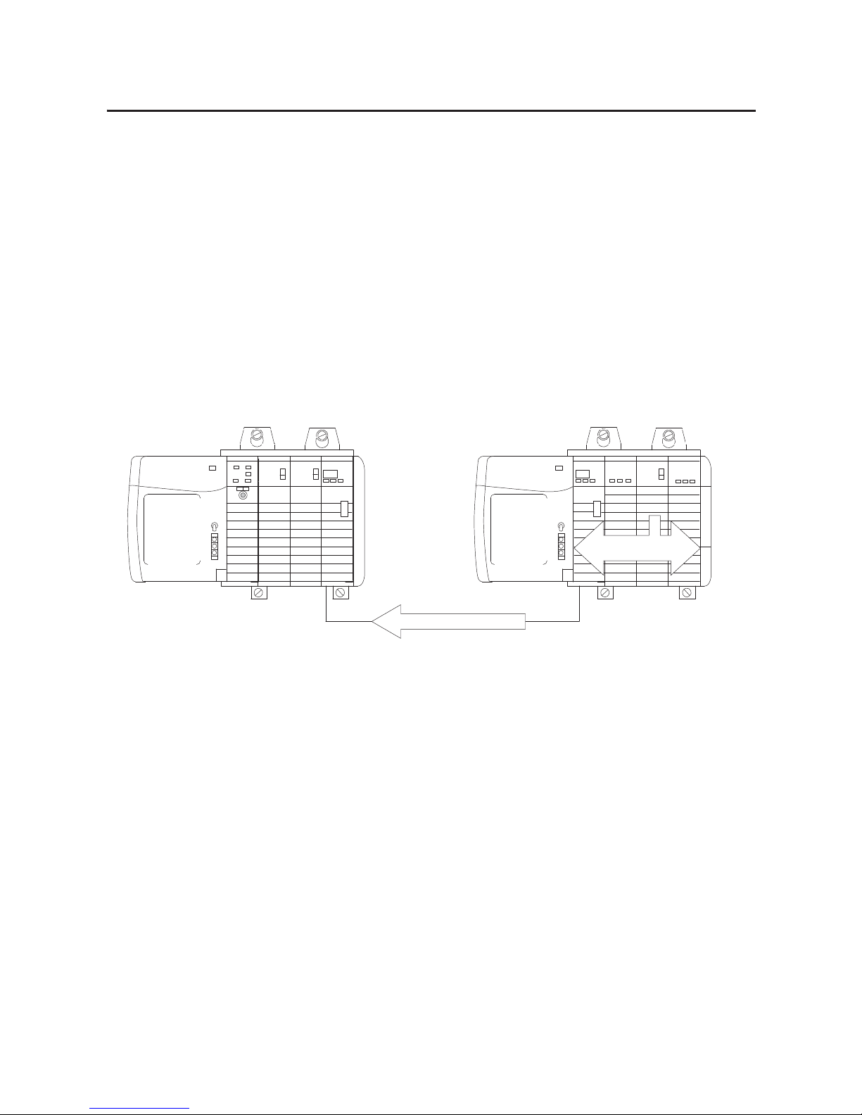
Multiple Owner-Controllers
of Input Modules
If a connection is lost between an owner-controller and a module, the connection
is also lost between any controllers listening to that module. As a result, the
ControlLogix system lets you define more than one owner-controller for input
modules.
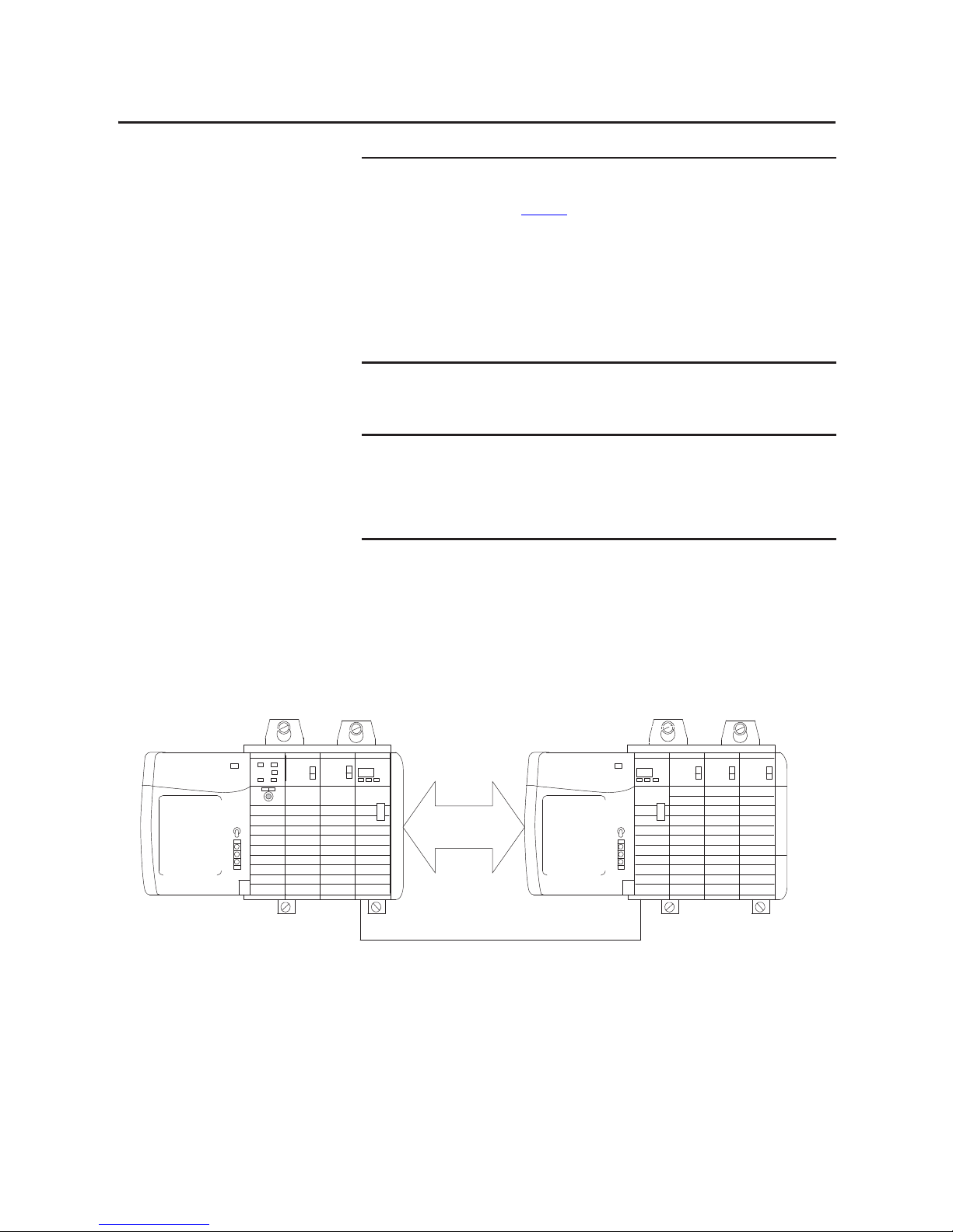
In the illustration below, controller A and controller B both have been config ured
to be owner-controllers of the same input module.
Figure 6 - Identical Owner-Controller Configurations for Input Module
IMPORTANT
In Listen-only mode, controllers continue to receive data multicast from the I/O
module as long as the connection between the owner-controller and I/O
module is maintained.
If the connection between the owner-controller and module is broken, the
module stops multicasting data and connections to all listening controllers are
also broken.
IMPORTANT
Only input modules can have multiple owner-controllers. If multiple ownercontrollers are connected to the same input module, they must maintain
identical configurations for that module.
Input Module
Configuration
Data
Xxxxx
Xxxxx
Xxxxx
Input Module
Configuration
Data
Xxxxx
Xxxxx
Xxxxx
41056
Initial Configuration Initial Configuration
A
B
Input
A B
Page 35

Rockwell Automation Publication 1756-UM058G-EN-P - November 2012 35
Digital I/O Operation in the ControlLogix System Chapter 2
As soon as a controller receives its user program, it will try to establish a
connection with the input module. A connection is established with the
controller whose configuration data arrives first. When the second controller’s
configuration data arrives, the module compares it to its current configuration
data, which was received and accepted from the first controller.
If the configuration data sent by the second controller matches the data sent by
the first controller, that connection is also accepted. If any parameter of the
second configuration data is different from the first, the module rejects the
connection and the user is informed by an error in the software or via program
logic.
The advantage of multiple owners over a Listen-only connection is that either of
the controllers can break the connection to the module, and the module will
continue to operate and multicast data to the system through the connection
maintained by the other controller.
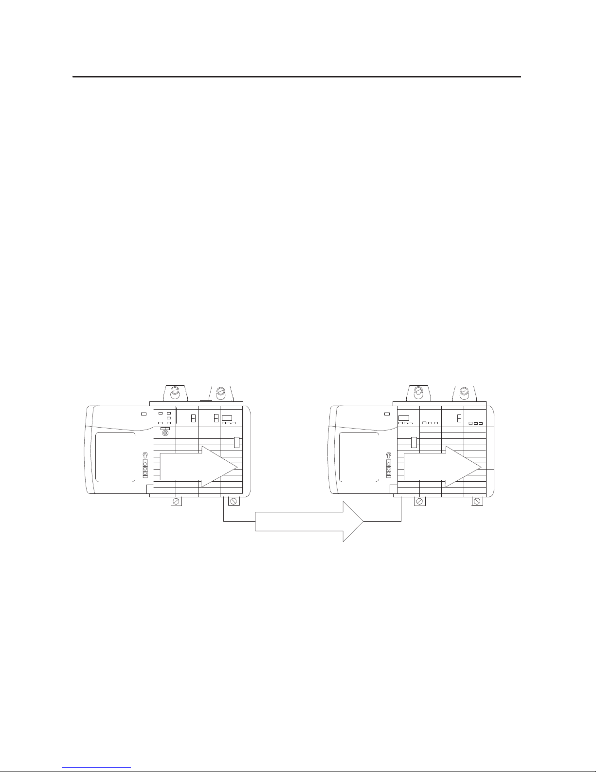
Configuration Changes in an
Input Module with Multiple
Owners
You must be careful when changing an input module’s configuration data in a
multiple owner scenario. If the configuration data is changed in owner A and sent
to the module, that configuration data is accepted as the new configuration for
the module. Owner B will continue to listen unaware that any changes have been
made in the module’s behavior, as illustrated below.
Figure 7 - Module Configuration Changes with Multiple Owners
41057
Input Module
Configuration
Data
Xxxxx
Zzzzz
Xxxxx
Input Module
Configuration
Data
Xxxxx
Xxxxx
Xxxxx
Initial Configuration Initial Configuration
A BInput
AB
IMPORTANT
A message in RSLogix 5000 software alerts you to the possibility of a multiple
owner-controller situation and lets you inhibit the connection before changing
the module’s configuration. When changing the configuration for a module
with multiple owners, we recommend the connection be inhibited.
Page 36

36 Rockwell Automation Publication 1756-UM058G-EN-P - November 2012
Chapter 2 Digital I/O Operation in the ControlLogix System
To prevent other owner-controllers from receiving potentially erroneous data, use
these steps when changing a module’s configuration in a multiple owner scenario
while online.
1. For each owner-controller, inhibit the connection to the module either in
the software on the Connection tab or the message dialog box warning you
of the multiple owner condition.
2. Make the appropriate configuration data changes in the software. For more
information about using RSLogix 5000 software to change the
configuration, see Chapter
7.
3. Repeat step 1
and step 2 for all owner-controllers, making the exact same
changes in each.
4. Clear the Inhibit checkbox in each owner-controller configuration.
Page 37

Rockwell Automation Publication 1756-UM058G-EN-P - November 2012 37
Chapter 3
Common Module Features
Input Module Compatibility
ControlLogix digital input modules interface to sensing devices and detect
whether they are On or Off.
ControlLogix input modules convert AC or DC On/Off signals from user
devices to appropriate logic level for use within the processor. Typical input
devices include the following:
• Proximity switches
• Limit switches
• Selector switches
• Float switches
• Push button switches
When designing systems with ControlLogix input modules, consider these
factors:
• Voltage necessary for your application
• Current leakage
• Whether you need a solid state device
• Whether your application should use sinking or sourcing wiring
Top ic P age
Input Module Compatibility 37
Output Module Compatibility 38
Common Features 39
Common Features Specific to Input Modules 50
Common Features Specific to Output Modules 54
Fault and Status Reporting between Input Modules and Controllers 64
Fault and Status Reporting between Output Modules and Controllers 65
Page 38

38 Rockwell Automation Publication 1756-UM058G-EN-P - November 2012
Chapter 3 Common Module Features
Output Module Compatibility
ControlLogix output modules can be used to drive a variety of output devices.
Typical output devices compatible with ControlLogix outputs include these
items:
• Motor starters
• Solenoids
• Indicators
Follow these guidelines when designing a system:
• Make sure that the ControlLogix outputs can supply the necessary surge
and continuous current for proper operation.
• Make sure that the surge and continuous current are not exceeded.
Damage to the module could result.
When sizing output loads, refer to the documentation supplied with the output
device for the surge and continuous current needed to operate the device.
The ControlLogix standard digital outputs are capable of directly driving the
ControlLogix standard digital inputs. The exceptions are the AC and DC
diagnostic input modules. When diagnostics are used, a shunt resistor is required
for leakage current.
For information on the compatibility of motor starters with ControlLogix
output modules, see Appendix
E.
Page 39

Rockwell Automation Publication 1756-UM058G-EN-P - November 2012 39
Common Module Features Chapter 3
Common Features
The table below lists features common to all ControlLogix digital I/O modules.
Removal and Insertion Under Power
All ControlLogix I/O modules may be inserted and removed from the chassis
while power is applied. This feature allows greater availability of the overall
control system. While the module is being removed or inserted, there is no
additional disruption to the rest of the control process. This helps prevent an
entire production line from having to be shut down.
Module Fault Reporting
ControlLogix digital I/O modules provide both hardware and software
indication when a module fault has occurred. Each module’s fault status indicator
and RSLogix 5000 software will graphically display this fault and include a fault
message describing the nature of the fault.
This feature lets you determine how your module has been affected and what
action should be taken to resume normal operation.
The 1756-OB16IEF module extends this feature by enabling you to define the
duration of time before the module transitions to On or Off after a fault occurs.
For more information, see Programmable Fault State Delays
on page 95.
Top ic Pag e
Removal and Insertion Under Power 39
Module Fault Reporting 39
Software Configurable 40
Electronic Keying 40
Module Inhibiting 46
Use the System Clock to Timestamp Inputs and Schedule Outputs 47
Producer/Consumer Communication 50
Status Indicator Information 50
Page 40

40 Rockwell Automation Publication 1756-UM058G-EN-P - November 2012
Chapter 3 Common Module Features
Software Configurable
RSLogix 5000 software provides an interface to configure each module. All
module features are enabled or disabled through the I/O configuration within
the software.
You can also use the software to retrieve the following information from any
module in the system:
• Serial number
• Firmware revision information
• Product code
• Ve n d o r
• Error and fault information
• Diagnostic counters
By eliminating tasks, such as setting hardware switches and jumpers, the software
makes module configuration easier and more reliable.
Electronic Keying
The electronic keying feature automatically compares the expected module, as
exists in the RSLogix 5000 I/O Configuration tree, to the physical module in the
chassis before I/O communication begins. You can use electronic keying to help
prevent communication to a module that does not match the type and revision
expected.
For each module in the I/O Configuration tree, the user-selected keying option
determines if and how an electronic keying check is performed. Typically, three
keying options are available:
• Exact Match
• Compatible Keying
• Disable Keying
You must carefully consider the benefits and implications of each keying option
when selecting between them. For some specific module types, fewer options are
available.
Page 41
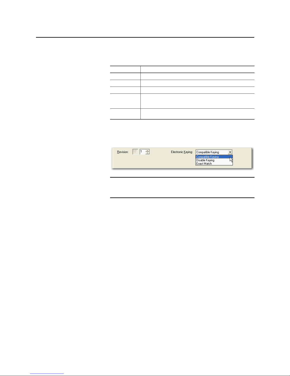
Rockwell Automation Publication 1756-UM058G-EN-P - November 2012 41
Common Module Features Chapter 3
Electronic keying is based on a set of attributes unique to each product revision.
When a Logix5000 controller begins communicating with a module, this set of
keying attributes is considered.
You can find revision information on the General tab of a module’s Properties
dialog box.
Figure 8 - General Tab
Exact Match
Exact Match keying requires all keying attributes, that is, Vendor, Product Type,
Product Code (catalog number), Major Revision, and Minor Revision, of the
physical module and the module created in the software to match precisely to
establish communication. If any attribute does not match precisely, I/O
communication is not permitted with the module or with modules connected
through it, as in the case of a communication module.
Use Exact Match keying when you need the system to verify that the module
revisions in use are exactly as specified in the project, such as for use in highlyregulated industries. Exact Match keying is also necessary to enable Automatic
Firmware Update for the module via the Firmware Supervisor feature from a
Logix5000 controller.
Attribute Description
Vendor The manufacturer of the module, for example, Allen-Bradley.
Product Type The general type of the module, for example, communication adapter, AC drive, or digital I/O.
Product Code The specific type of module, generally represented by its cat alog number, suc h as 1756-IB16I.
Major Revision A number that represents the functional capabilities and data exchange formats of the
module. Typically, a later major revision supports at least all of the data formats supported by
an earlier major revision of the same catalog number.
Minor Revision A number that indicates the module’s spec ific firmware revision. Minor revisions typically do
not impact data compatibility but may indicate performance or behavior improvement.
IMPORTANT
Changing electronic keying selections online may cause the I/O
communication connection to the module to be disrupted and may result in a
loss of data
Page 42

42 Rockwell Automation Publication 1756-UM058G-EN-P - November 2012
Chapter 3 Common Module Features
Compatible Keying
Compatible Keying indicates that the module determines whether to accept or
reject communication. Different module families, communication adapters, and
module types implement the compatibility check differently based on the family
capabilities and on prior knowledge of compatible products.
Compatible Keying is the default setting. Compatible Keying allows the physical
module to accept the key of the module configured in the software, provided that
the configured module is one the physical module is capable of emulating. The
exact level of emulation required is product and revision specific.
With Compatible Keying, you can replace a module of a certain Major Revision
with one of the same catalog number and the same or later, that is higher, Major
Revision. In some cases, the selection makes it possible to use a replacement that
is a different catalog number than the original. For example, you can replace a
1756-CNBR module with a 1756-CN2R module.
Release notes for individual modules indicate the specific compatibility details.
EXAMPLE
In the following scenario, Exact Match keying prevents I/O
communication.
The module configuration is for a 1756-IB16D module with module revision
3.1. The physical module is a 1756-IB16D module with module revision 3.2. In
this case, communication is prevented because the Minor Revision of the
module does not match precisely.
IMPORTANT
Changing electronic keying selections online may cause the I/O
Communication connection to the module to be disrupted and may result in a
loss of data.
Module Configuration
Vendor = Allen-Bradley
Product Type = Digital Input Module
Catalog Number = 1756-IB16D
Major Revision = 3
Minor Revision = 1
Physical Module
Vendor = Allen-Bradley
Product Type = Digital Input Module
Catalog Number = 1756-IB16D
Major Revision = 3
Minor Revision = 2
Communication is prevented
Page 43
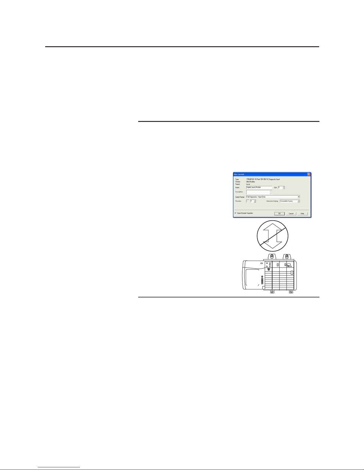
Rockwell Automation Publication 1756-UM058G-EN-P - November 2012 43
Common Module Features Chapter 3
When a module is created, the module developers consider the module’s
development history to implement capabilities that emulate those of the previous
module. However, the developers cannot know future developments. Because of
this, when a system is configured, we recommend that you config ure your module
by using the earliest, that is, lowest, revision of the physical module that you
believe will be used in the system. By doing this, you can avoid the case of a
physical module rejecting the keying request because it is an earlier revision than
the one configured in the software.
EXAMPLE
In the following scenario, Compatible Keying prevents I/O
communication.
The module configuration is for a 1756-IB16D module with module revision
3.3. The physical module is a 1756-IB16D module with module revision 3.2. In
this case, communication is prevented because the minor revision of the
module is lower than expected and may not be compatible with 3.3.
Module Configuration
Vendor = Allen-Bradley
Product Type = Digital Input Module
Catalog Number = 1756-IB16D
Major Revision = 3
Minor Revision = 3
Physical Module
Vendor = Allen-Bradley
Product Type = Digital Input Module
Catalog Number = 1756-IB16D
Major Revision = 3
Minor Revision = 2
Communication is prevented
Page 44

44 Rockwell Automation Publication 1756-UM058G-EN-P - November 2012
Chapter 3 Common Module Features
Disabled Keying
Disabled Keying indicates the keying attributes are not considered when
attempting to communicate with a module. Other attributes, such as data size
and format, are considered and must be acceptable before I/O communication is
established. With Disabled Keying, I/O communication may occur with a
module other than the type specified in the I/O Configuration tree with
unpredictable results. We generally do not recommend using Disabled Keying.
If you use Disabled Keying, you must take full responsibility for understanding
whether the module being used can fulfill the functional requirements of the
application.
EXAMPLE
In the following scenario, Compatible Keying allows I/O communication.
The module configuration is for a 1756-IB16D module with module revision
2.1. The physical module is a 1756-IB16D module with module revision 3.2. In
this case, communication is allowed because the major revision of the physical
module is higher than expected and the module determines that it is
compatible with the prior major revision.
IMPORTANT
Changing electronic keying selections online may cause the I/O
communication connection to the module to be disrupted and may result in a
loss of data.
ATT EN TI ON : Be extremely cautious when using Disabled Keying; if used
incorrectly, this option can lead to personal injury or death, property damage,
or economic loss.
Module Configuration
Vendor = Allen-Bradley
Product Type = Digital Input Module
Catalog Number = 1756-IB16D
Major Revision = 2
Minor Revision = 1
Physical Module
Vendor = Allen-Bradley
Product Type = Digital Input Module
Catalog Number = 1756-IB16D
Major Revision = 3
Minor Revision = 2
Communication is allowed
Page 45

Rockwell Automation Publication 1756-UM058G-EN-P - November 2012 45
Common Module Features Chapter 3
EXAMPLE
In the following scenario, Disable Keying prevents I/O communication.
The module configuration is for a 1756-IA16 digital input module. The physical
module is a 1756-IF16 analog input module. In this case, communication is
prevented because the analog module rejects the data formats that
the digital module configuration requests.
EXAMPLE
In the following scenario, Disable Keying allows I/O communication:
The module configuration is for a 1756-IA16 digital input module. The physical
module is a 1756-IB16 digital input module. In this case, communication is
allowed because the two digital modules share common data formats.
Module Configuration
Vendor = Allen-Bradley
Product Type = Digital Input Module
Catalog Number = 1756-IA16
Major Revision = 3
Minor Revision = 1
Physical Module
Vendor = Allen-Bradley
Product Type = Analog Input Module
Catalog Number = 1756-IF16
Major Revision = 3
Minor Revision = 2
Communication is prevented
Module Configuration
Vendor = Allen-Bradley
Product Type = Digital Input Module
Catalog Number = 1756-IA16
Major Revision = 2
Minor Revision = 1
Physical Module
Vendor = Allen-Bradley
Product Type = Digital Input Module
Catalog Number = 1756-IB16
Major Revision = 3
Minor Revision = 2
Communication is allowed
Page 46

46 Rockwell Automation Publication 1756-UM058G-EN-P - November 2012
Chapter 3 Common Module Features
Module Inhibiting
Module inhibiting lets you indefinitely suspend a connection between an
owner-controller and a digital I/O module without having to remove the module
from the configuration. This process lets you temporarily disable communication
to a module, such as to perform maintenance. You can use module inhibiting in
these ways:
• You write a configuration for an I/O module but inhibit the module to
prevent it from communicating with the owner-controller. In this case, the
owner does not establish a connection and the configuration is not sent to
the module until the connection is uninhibited.
• In your application, a controller already owns a module, has downloaded
the configuration to the module, and is currently exchanging data over the
connection between the devices. In this case, you can inhibit the module
and the owner-controller behaves as if the connection to the module does
not exist.
You may need to use module inhibiting in these instances:
• Multiple controllers own the same digital input module. A change is
required in the module’s configuration. However, the change must be
made to the program in all controllers. In this case, you follow these steps.
a. Inhibit the module.
b. Change configuration in all controllers.
c. Uninhibit the module.
• You want to upgrade a digital I/O module. We recommend you use this
procedure.
a. Inhibit the module.
b. Perform the upgrade.
c. Uninhibit the module.
• You are using a program that includes a module that you do not physically
possess yet, and you do not want the controller to continually look for a
module that does not yet exist. In this case, you can inhibit the module in
your program until it physically resides in the proper slot.
IMPORTANT
Changing electronic keying selections online may cause the I/O
communication connection to the module to be disrupted and may result in a
loss of data.
IMPORTANT
Whenever you inhibit an output module, it enters Program mode, and all
outputs change to the state configured for Program mode. For example, if an
output module is configured so that the state of the outputs transition to zero
during Program mode, whenever that module is inhibited, outputs transition
to zero.
Page 47

Rockwell Automation Publication 1756-UM058G-EN-P - November 2012 47
Common Module Features Chapter 3
Use the System Clock to Timestamp Inputs and Schedule Outputs
This section describes how to use CST timestamps in standard and diagnostic
I/O modules and the CIP Sync timestamps in fast I/O modules.
Use Coordinated System Time with Standard and Diagnostic I/O Modules
Time masters generate a 64-bit coordinated system time (CST) for their
respective chassis. The CST is a chassis-specific time that is not synchronized
with, or in any way connected to, the time generated over the ControlNet
network to establish a network update time (NUT). For more information about
NUT, refer to Use RSNetWorx and RSLogix 5000 Software
on page 20.
You can configure your digital input modules to access the CST and timestamp
input data with a relative time reference of when that input data changes state.
The following table describes how you can use CST timestamps.
IMPORTANT
Because only one CST value is returned to the controller when any input point
changes state, we recommend that you use timestamping on only one input
point per module.
Topic Description
Timestamping for a
sequence of events
The CST can be used to establish a sequence of events occurring at a particular input module
point by timestamping the input data. To determine a sequence of events, you must do the
following:
• Set the input module’s communication format to CST Timestamped Input Data.
• Enable COS for the input point where a sequence will occur, and disable COS for all other
points on the module.
TIP
If you decide to configure multiple input points for COS, your
module generates a unique CST each time any of those input
points change state, as long as the changes do not occur within
500 s of each other.
If multiple input points configured for COS change state within
500 s of each other, a single CST value is generated for all
making it appear that they changed at exactly the same time.
Timestamping in
conjunction with
scheduled outputs
Timestamping can be used in conjunction with the scheduled outputs feature, so that after
input data changes state and a timestamp occurs, an output point will actuate at some
configured time in the future.
You can schedule outputs up to 16 seconds into the future. When you use timestamping of
inputs and scheduled outputs, you must do the following:
• Choose a communication or connection format for each input and output module that
allows timestamping. For more information, refer to Communication or Connection
Forma ts on page 131.
• Have a time master in the same chassis as both I/O modules.
• Disable COS for all input points on the input module except the point being timestamped.
TIP
For scheduled outputs to work most effectively, remember the
following items:
• The time to schedule outputs to transition in the future must
account for any controller, backplane, and network delays.
• The I/O modules must reside in the same rack as the time
master.
Page 48

48 Rockwell Automation Publication 1756-UM058G-EN-P - November 2012
Chapter 3 Common Module Features
Use CIP Sync Time with Fast I/O Modules
The 1756-IB16IF, 1756-OB16IEF, and 1756-OB16IEFS modules use CIP Sync
for both timestamps and scheduling.
CIP Sync is a CIP implementation of the IEEE 1588 PTP (Precision Time
Protocol). CIP Sync provides accurate real-time (Real-World Time) or Universal
Coordinated Time (UTC) synchronization of controllers and devices connected
over CIP networks. This technolog y supports highly distributed applications
that require timestamping, sequence of events recording, distributed motion
control, and increased control coordination.
The 1756-IB16IF, 1756-OB16IEF, and 1756-OB16IEFS modules are CIP Sync
slave-only devices. There must be another module on the network that will
function as a master clock. For more information on how to use CIP Sync
technology, see the Integrated Architecture and CIP Sync Configuration
Application Technique, publication IA-AT003
.
Fast I/O modules can be used to capture timestamps and schedule outputs like
CST-based modules while providing the following advantages:
• Fast I/O modules have much higher precision than CST-based modules.
• Inputs are timestamped by point, so multiple inputs can be configured for
COS without losing timestamp data.
• CIP Sync is system wide, so timestamp and schedule values are consistent
across all modules in the system. For instance, using 1756-IB16IF input
timestamps to schedule outputs on a 1756-OB16IEF module means the
controller, input module, and output module are not restricted to the same
chassis as is the case with CST-based I/O.
• Output modules use all 64 bits of the timestamp to schedule, so there are
no limits on schedule ranges.
Page 49

Rockwell Automation Publication 1756-UM058G-EN-P - November 2012 49
Common Module Features Chapter 3
Mixing CST and CIP Sync Modules in a ControlLogix System
CST is automatically enabled for each chassis that has been configured to use
CIP Sync. Therefore, it is possible to include modules that use CST for their time
base into systems that have been configured to use CIP Sync. Also, there is a
direct correlation between CIP Sync system time and the local chassis CST time.
The CIP Sync system time and local chassis CST time are related by this
equation:
CIP Sync system time = CST time + offset
The offset in the above equation is a value unique to each chassis and can be
obtained by using one of these methods:
• CSTOffset from the Wall Clock Time (WCT) object of a controller in
the chassis
• SystemOffset from the Time Synchronize object of a controller in the
chassis
• LocalClockOffset returned in an I/O connection from a CIP Sync capable
module in the chassis
The relationship described above enables CST and CIP Sync-based I/O to
interoperate as long as the offset in the chassis containing the CST-based module
is accessible.
Page 50

50 Rockwell Automation Publication 1756-UM058G-EN-P - November 2012
Chapter 3 Common Module Features
Producer/Consumer Communication
By using Producer/Consumer communication, ControlLogix I/O modules can
produce data without first being polled by a controller. The modules produce the
data and any other owner-controller device can decide to consume it.
For example, an input module produces data and any number of processors can
consume the data at the same time. This eliminates the need for one processor to
send the data to another processor. For more information about this process, see
Input Module Operation
on page 26.
Status Indicator Information
Each ControlLogix digital I/O module has a status indicator on the front of the
module that lets you check the health and operational status of a module. The
status indicator displays vary for each module.
See Appendix
A for examples of status indicators on ControlLogix digital I/O
modules.
Common Features
Specific to Input Modules
The table below lists features specific to ControlLogix digital input modules.
Status Description
I/O status
ST
This yellow display indicates the On/Off state of the field device.
IMPORTANT: For the 1756-OA8D and 1756-OA8E modules, the I/O status indicator does not
illuminate without field power applied.
Module status
OK
This green display indicates the module’s communication status.
Fault status
FLT
This display is only found on some modules and indicates the presence or absence of various
faults.
Fuse status
Fuse
This display is only found on electronically fused modules and indicates the state of the
module’s fuse.
Top ic Page
Data Transfer on Either Cyclic Time or Change of State 51
Set RPI 51
Enable Change of State 52
Software Configurable Filter Times 53
Isolated and Nonisolated Varieties of Input Modules 53
Multiple Input Point Densities 54
Page 51

Rockwell Automation Publication 1756-UM058G-EN-P - November 2012 51
Common Module Features Chapter 3
Data Transfer on Either Cyclic Time or Change of State
Digital input modules always send data at the RPI, but they send data at a change
of state only if the COS feature is enabled. COS is more efficient than RPI
because it multicasts data only when a change occurs.
The table describes the two ways a module sends data to the owner-controller.
Set RPI
The Connection tab on the Module Properties dialog box lets you enter an RPI.
The RPI guarantees the slowest rate at which data is multicast.
The module’s actual data transfer rate may be faster than the RPI setting. But, the
RPI provides a defined, maximum period of time when data is transferred to the
owner-controller.
Follow these steps to set an RPI value.
1. On the Module Properties dialog box, click the Connection tab.
2. In the Requested Packet Interval (RPI) field, enter an RPI value.
3. Click OK.
Method Description
RPI A user-defined rate at which the module updates the information sent to its owner-controller.
This is also known as Cyclic Data Transfer.
COS Configurable feature that, when enabled, instructs the module to update its owner-controller
with new data whenever a specified input point transitions from On to Off and Off to On. The data
will be sent at the RPI rate when there is no change of state. By default, this setting is always
enabled for input modules.
Page 52
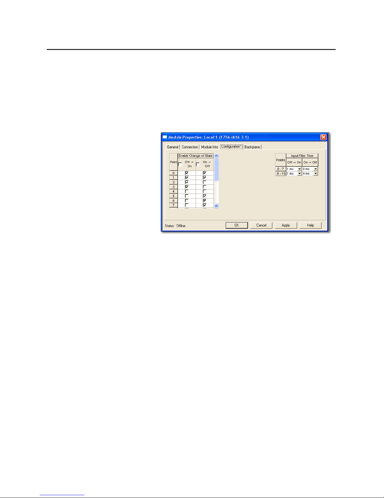
52 Rockwell Automation Publication 1756-UM058G-EN-P - November 2012
Chapter 3 Common Module Features
Enable Change of State
The Point column on the left side of the Configuration tab lets you set whether a
COS occurs when a field device transitions from Off to On or On to Off.
Follow these steps to enable or disable COS.
1. On the Module Properties dialog box, click the Configuration tab.
2. Do one of the following in the Enable Change of State columns:
• To enable COS for a point, check the corresponding Off to On or On
to Off checkbox.
• To disable COS for a point, clear the corresponding Off to On or On to
Off checkbox.
3. Click OK.
Page 53

Rockwell Automation Publication 1756-UM058G-EN-P - November 2012 53
Common Module Features Chapter 3
Software Configurable Filter Times
On to Off and Off to On filter times can be adjusted through
RSLogix 5000 software for all ControlLogix input modules. These filters
improve noise immunity within a signal. A larger filter value affects the length of
delay times for signals from these modules.
Follow these steps to configure the input filter time.
1. On the right side of the Configuration tab, choose the input filter times
from the Off
On and On O pull-down menus.
2. Click OK.
Isolated and Nonisolated Varieties of Input Modules
ControlLogix input modules provide isolated or nonisolated wiring options.
Some applications require power for the I/O circuits to originate on separate,
isolated power sources. Because these conditions require separate commons for
each channel, some input modules use individual isolation, or point-to-point
isolation so if one point faults, the others continue to operate.
Other types of isolation available with ControlLogix input modules are channelto-channel isolation and no isolation. Your application determines what type of
isolation is necessary and which input module to use.
IMPORTANT
Input filters on the 1756-IB16IF module function differently than other digital
I/O modules. For information about input filters on the 1756-IB16IF module,
see page 90
.
Page 54

54 Rockwell Automation Publication 1756-UM058G-EN-P - November 2012
Chapter 3 Common Module Features
Multiple Input Point Densities
ControlLogix input modules use either 8-, 16-, or 32-point densities for greater
flexibility in your application. A point is the termination where a wire attaches to
the input module from a field device. The module receives information from the
device to this designated point, thus signaling when activity occurs.
Common Features
Specific to Output Modules
The table below lists features specific to ControlLogix digital output modules.
IMPORTANT
Some features are not available on all output modules. The table indicates
which modules support each feature.
Topic Page Available Modules
Configurable Point-level Output States 55 All modules
Output Data Echo 56 All modules
Isolated and Nonisolated Varieties of Output Modules 56 All modules
Multiple Output Point Densities 57 All modules
Electronic Fusing 57 1756-OA8D
1756-OA8E
1756-OB16D
1756-OB16E
1756-OB8EI
1756-OB16IEF
1756-OB16IEFS
1756-OV16E
1756-OV32E
Field Power Loss Detection 60 1756-OA8E
Diagnostic Latch of Information 61 1756-OA8E
1756-OB16IEF
1756-OB16IEFS
Time-scheduled Output Control 63 1756-OB16IS
1756-OB16IEFS
Page 55

Rockwell Automation Publication 1756-UM058G-EN-P - November 2012 55
Common Module Features Chapter 3
Configurable Point-level Output States
Individual outputs can be configured to unique output states if the module goes
into Program mode or Fault mode.
Follow these steps to configure an output state.
1. On the Module Properties dialog box, click the Configuration tab.
2. From the Program Mode pull-down menu, choose whether the module’s
output state is On or Off during Program mode:
• On
• Off
• Hold (Retain current output state)
3. From the Fault Mode pull-down menu, choose whether the module’s
output state during Fault mode:
• On
• Off
• Hold (Retain current output state)
4. Click OK.
IMPORTANT
Whenever you inhibit an output module, it enters Program mode, and all
outputs change to the state configured for Program mode. For example, if an
output module is configured so that the state of outputs turn Off during
Program mode, whenever that module is inhibited, outputs turn Off.
Page 56

56 Rockwell Automation Publication 1756-UM058G-EN-P - November 2012
Chapter 3 Common Module Features
Output Data Echo
During normal operation, when a controller sends out an output command to the
ControlLogix system, the output module that is targeted for that command
returns the commanded state of the output to the system. This process verifies
that the module has received the command and will try to execute it.
Other devices can use this broadcast signal through a Listen-only connection to
determine the desired state of the output without having to interrogate the
owner-controller.
Monitor Fault Bits
The output data echo only matches the commanded state of the outputs if the
module is operating under normal conditions. If there is an anomaly with the
module, the commanded state and the output data echo may not match.
You can monitor the fault bits for your output points for fault conditions. If a
fault occurs, the fault bit is set and your program alerts you to the condition. In
this case, the output data echo may not match the commanded state of the
outputs.
If there is a mismatch between the commanded state of the outputs and the
output data echo, check your output module for the following conditions:
• Communication fault.
• Connection is inhibited.
• Blown fuse—The module will not turn on an output if an overload or
short circuit is detected.
• (1756-OA8D and 1756-OA8E only) Loss of field power—The module
will not turn on an output unless AC power is detected.
Isolated and Nonisolated Varieties of Output Modules
As with input modules, ControlLogix output modules provide isolated or
nonisolated wiring options. I/O modules provide point-to-point, group-togroup, or channel-to-channel wiring isolation. Your specific application will
determine what type of isolation is necessary and which output module to use.
IMPORTANT
Although some ControlLogix I/O modules provide nonisolated, field-side
wiring options, each I/O module maintains internal electrical isolation
between the system side and field side.
Page 57

Rockwell Automation Publication 1756-UM058G-EN-P - November 2012 57
Common Module Features Chapter 3
Multiple Output Point Densities
ControlLogix output modules use either 8-, 16-, or 32-point densities for greater
flexibility in your application. A point is the termination where a wire attaches to
the I/O module from a device. The I/O gets information from the device to this
designated point, thus signaling when activity occurs.
Electronic Fusing
Some digital outputs have internal electronic or mechanical fusing to prevent too
much current from flowing through the module. This feature protects the
module from electrical damage. Other modules require external fusing.
Modules that use electronic fusing are fused on either a per point basis or per
group basis to protect output points from the surge of too much current. If too
much current begins to flow through a point, the fuse is tripped and a point-level
fault is sent to the controller. A corresponding tag can be examined in the event of
a fault. For more information about fault tags, see Appendix
B.
These modules use electronic fusing:
• 1756-OA8E
• 1756-OB8EI
• 1756-OA8D
• 1756-OB16D
• 1756-OB16E
• 1756-OV16E
• 1756-OV32E
• 1756-OB16IEF
• 1756-OB16IEFS
Refer to Tab l e 3
to determine what fuse to use in your application. If your module
does not support fusing, you can use a fused IFM to protect outputs. See
publication 1492-TD008
.
Table 3 - Recommended Fuses
Circuit Type Cat. No. Fusing on the module Recommended Fuse Fuse Supplier
AC 1756-OA8
(1)
None—Fused IFM can be used to protect outputs
(9)
5x20mm
6.3A Medium lag
SAN-O Industry Corp.
(SOC) p/n
MT 4-6.3A
1756-OA8D
(2) (3)
Yes—Fused on a per point basis Electronically fused
1756-OA8E
(2) (3)
1756-OA16
(1) (4) (5)
Yes—Fused on a per group basis 5x20mm
3.15A Slo-Blow
1500A Interruption current
Littelfuse p/n
H2153.15
1756-OA16I
(1)
None—Fused IFM can be used to protect outputs
(9)
5x20mm
6.3A Medium lag
SOC p/n
MT 4-6.3A
1756-ON8
Page 58

58 Rockwell Automation Publication 1756-UM058G-EN-P - November 2012
Chapter 3 Common Module Features
DC 1756-OB8
(6)
None—Fused IFM can be used to protect outputs
(9)
5x20mm
4A Quick acting
SOC p/n
MQ2-4A
1756-OB81
(6)
1756-OB8EI
(2) (3) (6)
Yes—Fused on a per point basis Electronically fused
1756-OB16D
(2) (3) (7)
1756-OB16E
(2) (3) (6)
Yes—Fused on a per group basis
1756-OB16I
(6) (8)
None—Fused IFM can be used to protect outputs
(9)
5x20mm
4A Quick acting
SOC p/n
MQ2-4A
1756-OB16IEF
(2) (3) (6)
Yes—Fused on a per point basis Electronically fused
1756-OB16IEFS
(2) (3) (6)
1756-OB16IS
(6) (8)
None—Fused IFM can be used to protect outputs
(9)
5x20mm
4A Quick acting
SOC p/n
MQ2-4A
1756-OB32
(6) (8)
5x20mm
800mA
Littelfuse p/n
SP001.1003 or
Schurter p/n
216.800
1756-OC8
(6)
5x20mm
4A Quick acting
SOC p/n
MQ2-4A
1756-OG16
(6)
1756-OH8I
(6) (8)
1756-OV16E
(2) (3) (6)
Yes—Fused on a per group basis Electronically fused
1756-OV32E
(2) (3) (6)
Relay 1756-OW16I
(8)
None—Fused IFM can be used to protect outputs
(9)
5x20mm
6.3A Medium lag
SOC p/n
MT 4-6.3A
1756-OX8I
(8)
(1) For voltages above 132V AC, the Interface Modules (IFM) are not an acceptable means to provide external fusing. A rated terminal block for the intended application must be used.
(2) Electronic protection is not intended to replace fuses, circuit breakers, or other code-required wiring protection devices.
(3) The electronic protection of this module has been designed to provide protection for the module from short-circuit conditions. The protection is based on a thermal cut-out principle. In the event of a
short-circuit condition on an output channel, that channel will limit the current within milliseconds after its thermal cut-out temperature has been reached. All other channels with a NUT of that group
will continue to operate as directed by the module master (CPU, bridge, and so forth).
(4) A fuse is provided on each common of this module for a total of two fuses. The fuses are designed to protect the module from short circuit conditions. The fuse does not provide overload protection. In the
event of an overload on an output channel, it i s likely that the fuse will not blow and the output device associated with that channel will be damaged. To provide overload protection for your application,
user supplied fuses should be externally installed.
(5) If a short circuit condition occurs on any channel within this module’s group, the entire group is turned Off.
(6) The module does not provide protection against reverse polarity wiring or wiring to AC power sources.
(7) The electronic protection of this module has been designed to provide protection for the module from short-circuit conditions. The protection is based on a thermal cut-out principle. In the event of a
short-circuit condition on an output channel, that channel will limit the current within milliseconds after its thermal cut-out temperature has been reached. Other channels could produce a false error on
the output verify fault signal due to the supply dropping below the minimum detect level of 19.2V DC. The output channels that are affected by this phenomena will continue to operate as directed by the
module master (CPU, bridge, and so forth). What this means is that the output verify fault signals of the other channels should be checked and reset if a short-circuit on one channel occurs.
(8) The recommended fuse for this module has been sized to provide short circuit protection for wiring only to external loads. In the event of a short circuit on an output channel, it is likely that the transistor
or relay associated with that channel will be damaged and the module should be replaced or a spare output channel used for the load. The fuse does not provide overload protection. In the event of an
overload on an output channel, it is likely that the fuse will not blow and the transistor or relay associated with that channel will be damaged. To provide overload protection for your application, user
supplied fuse should be installed externally and properly sized to match the individual load characteristics.
(9) The ControlLogix system has been agency certified using only the ControlLogix RTBs (1756-TBCH, 1756-TBNH, 1756-TBSH and 1756-TBS6H). Any application that requires agency certification of the
ControlLogix system using other wiring termination methods may require application specific approval by the certifying agency.
Table 3 - Recommended Fuses (continued)
Circuit Type Cat. No. Fusing on the module Recommended Fuse Fuse Supplier
Page 59
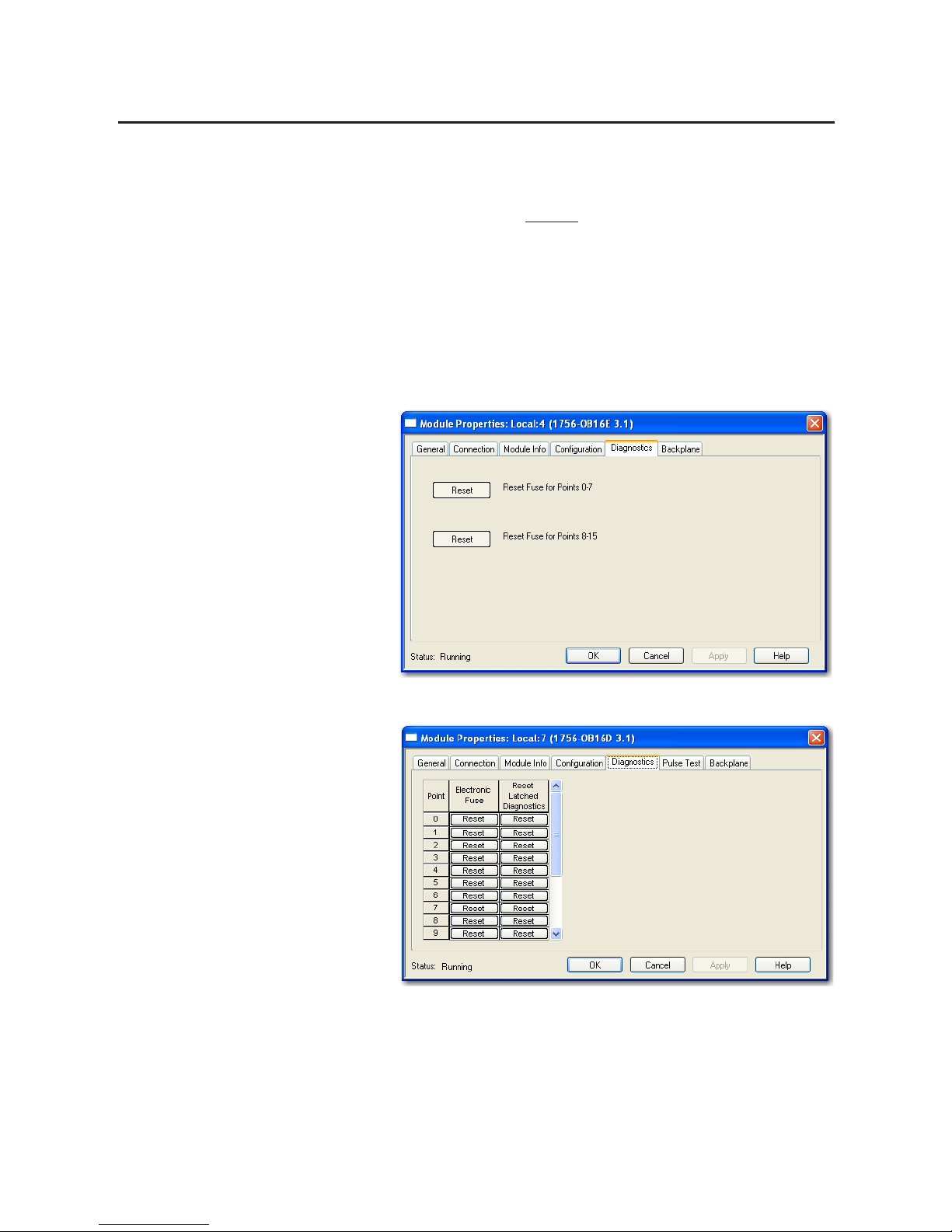
Rockwell Automation Publication 1756-UM058G-EN-P - November 2012 59
Common Module Features Chapter 3
You can reset an electronic fuse through RSLogix 5000 software during online
monitoring or through program logic running on a controller. If your module
uses point-level fusing, you can reset a fuse with a CIP Generic Message
instruction, as described on page 227
.
Follow these steps to reset an electronic fuse through RSLogix5000 software
during online monitoring.
1. On the Module Properties dialog box, click the Diagnostics tab.
The fields on the Diagnostic tab vary depending on whether your module
supports fusing on a per point basis or a per group basis.
2. Click Reset for the output points for which to reset a fuse.
3. Click OK.
Fusing on a per group basis
Fusing on a per point basis
Page 60

60 Rockwell Automation Publication 1756-UM058G-EN-P - November 2012
Chapter 3 Common Module Features
Field Power Loss Detection
For the standard digital output modules, the Field Power Loss detection feature is
found on the 1756-OA8E module only. When field power to the module is lost,
or zero cross cannot be detected, a point-level fault is sent to the controller to
identify the exact point faulted.
This feature has a corresponding tag that can be examined in the user program in
the event of a fault. For information on these tags, see Chapter A
.
Follow these steps to enable or disable diagnostics for field power loss.
1. On the Module Properties dialog box, click the Configuration tab.
2. Do one of the following in the Enable Diagnostics for Field Power Loss
column:
• To enable field power loss detection for a specific point, check the
corresponding check box.
• To disable field loss detection for a specific point, clear the
corresponding checkbox.
3. Click OK.
IMPORTANT
Only enable Field Power Loss detection for points that are in use. If this feature
is enabled for points that are not in use, you will receive faults for those points
during operation.
Page 61

Rockwell Automation Publication 1756-UM058G-EN-P - November 2012 61
Common Module Features Chapter 3
Diagnostic Latch of Information
The diagnostic latch feature is available for the 1756-OA8E modules only.
Diagnostic latching allows this module to latch a fault in the set position once it
has been triggered, even if the error condition causing the fault to occur
disappears.
Follow these steps to enable diagnostic latch of information.
1. On the Module Properties dialog box, click the Configuration tab.
2. Do one of the following in Enable Diag. Latching column:
• To enable diagnostic latching for a specific point, check the
corresponding checkbox.
• To disable diagnostic latching for a specific point, clear the
corresponding checkbox.
3. Click OK.
Page 62
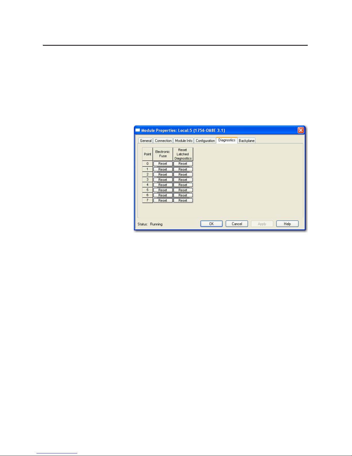
62 Rockwell Automation Publication 1756-UM058G-EN-P - November 2012
Chapter 3 Common Module Features
Latched diagnostic features can be cleared by using these methods:
• Reset Diagnostic Latch service
• Software reset during online monitoring
• Cycling power to the module’s
Follow these steps to a reset a latched fault through RSLogix 5000 software
during online monitoring.
1. On the Modules Properties screen, click the Diagnostics tab.
2. In the Reset Latched Diagnostics column, click Reset next to the output
point for which to reset a latched fault.
3. Click OK.
Page 63

Rockwell Automation Publication 1756-UM058G-EN-P - November 2012 63
Common Module Features Chapter 3
Time-scheduled Output Control
Time-scheduled output control is available for these modules:
• 1756-OB16IS—Provides time-scheduled output control in CST time for
outputs 0…7. Allows for schedules with a minimum interval of 100 µs.
• 1756-OB16IEFS—Provides time-scheduled output control in CIP Sync
time for outputs 0…15. Allows for schedules with a minimum interval of
5µs.
By using the time-scheduled output control feature, the module can turn the
outputs On or Off at a scheduled time. You can set the time for the output to
turn On or Off in program logic. The modules manage the time locally, so that
the output is turned On or Off at the specified time.
MAOC Instructions with Time-scheduled Output Control
The Motion Axis Output Cam (MAOC) instruction provides position-based
control of outputs by using position and velocity information of any motion axis.
When the 1756-OB16IS or 1756-OB16IEFS module is specified as the output
destination for the MAOC instruction, the MAOC instruction automatically
handles time-based scheduling for outputs. The benefit of using output
scheduling in this manner is that the resolution of the output control is improved
from the motion coarse update rate (typically 1…32 ms) to 100 µs for outputs
0…7 on the 1756-OB16IS module and 10 µs for outputs 0…15 on the 1756OB16IEFS module.
You can also use outputs 8…15 on the 1756-OB16IS module with the MAOC
instruction. However, only outputs 0…7 have 100 µs resolution. Outputs 8…15
are updated at the motion coarse update rate.
For more information about using the MAOC instruction with scheduled
output modules, refer to the Position-based Output Control with the
MAOC Instruction Application Technique, publication 1756-AT017
.
Module Major Revision Considerations with Timestamping
When using timestamping for inputs or diagnostic timestamping of I/O
modules, the following conditions may occur depending on the module’s major
revision:
• If the module has a Major Revision = 1, it always returns a positive
timestamping value.
• If the module has a Major Revision > 2, it returns a negative timestamping
value until the module is synchronized with the owner-controller and the
first change of state condition occurs.
Page 64
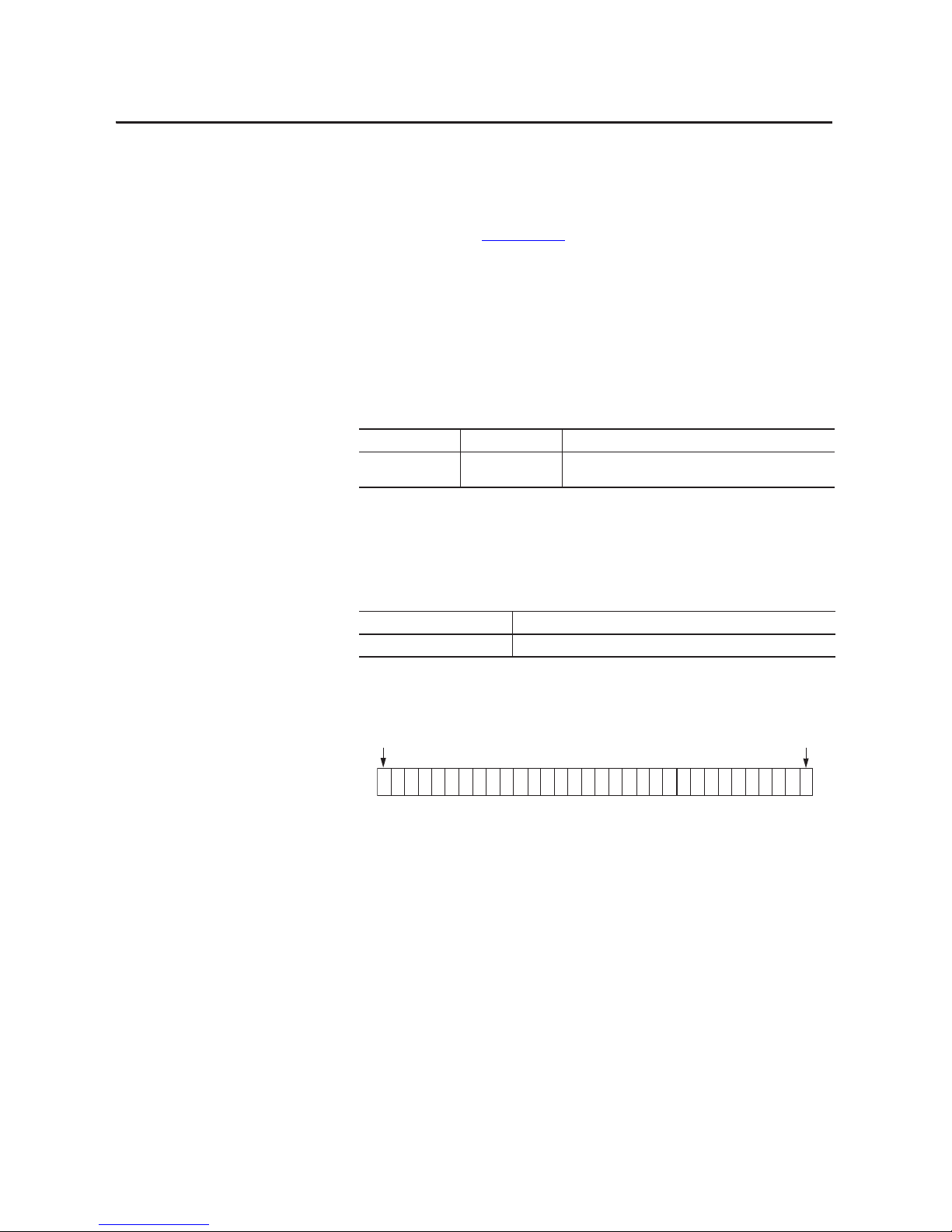
64 Rockwell Automation Publication 1756-UM058G-EN-P - November 2012
Chapter 3 Common Module Features
Use the Module Properties dialog box in RSLogix 5000 software to determine if
the module has been synchronized with the owner-controller and whether the
controller is synchronized with the CST. For more information on synchronizing
owner-controllers and modules with the CST, see the ControlLogix System User
Manual, publication 1756-UM001
.
Fault and Status Reporting
between Input Modules and
Controllers
ControlLogix digital input modules multicast fault and status data to any ownercontroller or listening controller. All input modules maintain a module-fault
word, the highest level of fault reporting.
The table lists the fault word and the associated tag that can be examined in
program logic to indicate when a fault has occurred for a standard input module.
All words are 32-bit, although only the number of bits appropriate for each
module’s density are used. For example, the 1756-IA16I module has a modulefault word of 32 bits. But, because this is a 16-point module, only 16 bits (0…15)
are used in the module-fault word.
The following illustration offers an overview of the fault reporting process on
ControlLogix standard digital input modules.
Table 4 - Fault Word on Input Modules
Word Tag Name Description
Module-fault Fault Provides fault summary reporting. Available on all digital input
modules.
Table 5 - Bits Set in Module-fault Word
Condition Bits Set
Communication fault All 32 bits are set to 1, regardless of the module’s density.
Module-fault Word
All Modules
42676
Bit 31 Bit 0
A communication fault sets all bits in the module-fault word.
Page 65

Rockwell Automation Publication 1756-UM058G-EN-P - November 2012 65
Common Module Features Chapter 3
Fault and Status Reporting
between Output Modules
and Controllers
ControlLogix digital output modules multicast fault and status data to any
owner-controller or listening controller. Like input modules, output modules
maintain a module-fault word, the highest level of fault reporting. However,
some output modules use additional words to indicate fault conditions.
The table lists the fault words and the associated tags that can be examined in
program logic to indicate when a fault has occurred for a standard output
module.
All words are 32-bit, although only the number of bits appropriate for each
module’s density are used. For example, the 1756-OB8 module has a modulefault word of 32 bits. But, because this is a eight-point module, only the first eight
bits (0…7) are used in the module-fault word.
Fault bits in the fuse blown word and field power loss word are logically entered
into the module-fault word. Depending on the module type, a bit set in the
module-fault word can mean multiple things, as indicated in the following table.
Table 6 - Fault Words on Output Modules
Word Tag Name Description
Module-fault Fault Provides fault summary reporting. Available on all digital output
modules.
Fuse blown FuseBlown Indicates a point/group fuse blown on the module. Available only on
1756-OA16, 1756-OA8D, 1756-OA8E, 1756-OB16D, 1756-OB16E,
1756-OB16EIF, 1756-OB8EI, 1756-OV16E, and 1756-OV32E modules.
For more information, see Electronic Fusing
on page 57.
Field power loss FieldPwrLoss Indicates a loss of field power to a point on the module. Available on
the 1756-OA8E module only. For more information, see Field Power
Loss Detection on page 60.
Table 7 - Bits Set in Module-fault Word
Condition Bits Set
Communication fault All 32 bits are set to 1, regardless of the module’s density.
Fuse bl own
Only the bit affected is set to 1.
Field power loss
Page 66
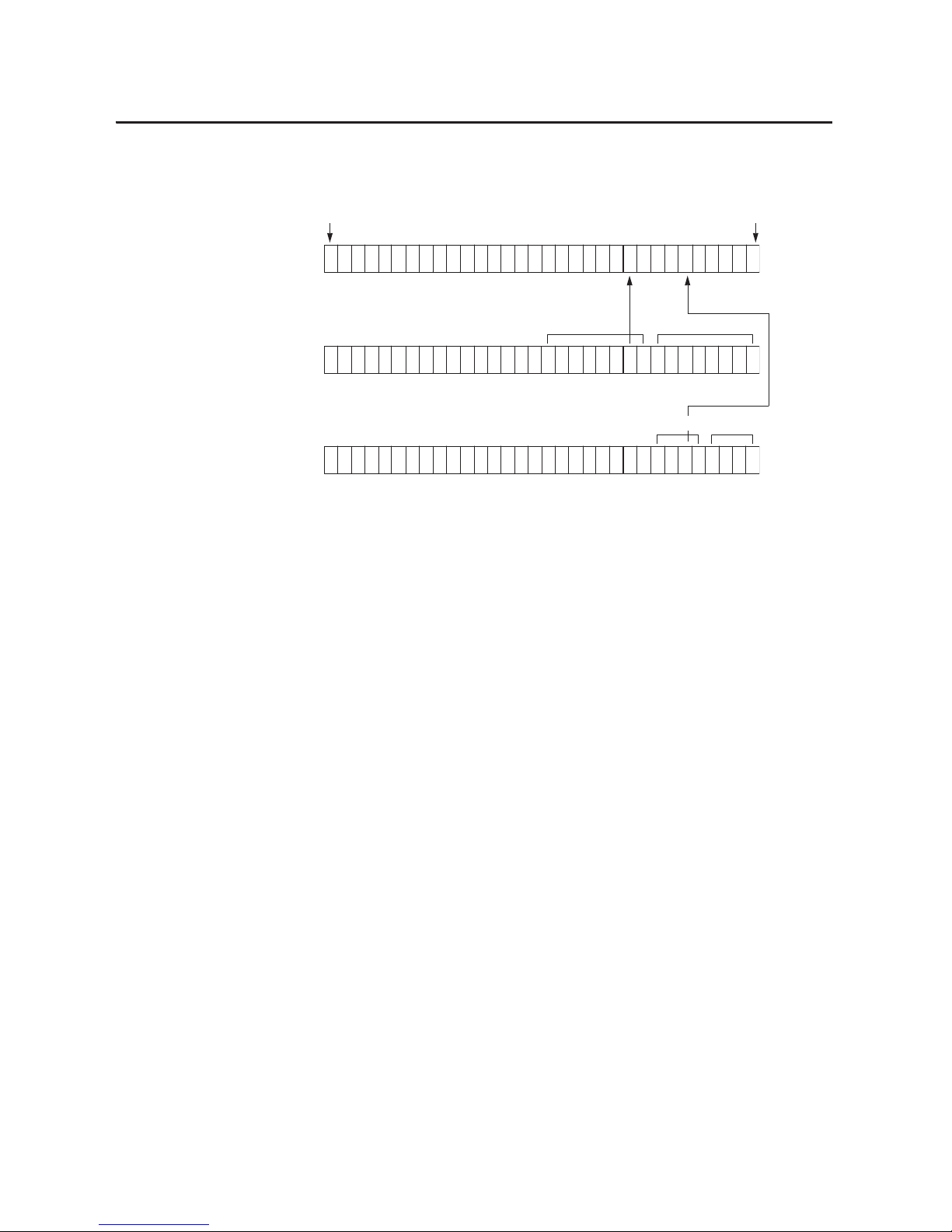
66 Rockwell Automation Publication 1756-UM058G-EN-P - November 2012
Chapter 3 Common Module Features
The following illustration offers an overview of the fault reporting process on
ControlLogix digital output modules.
Module-fault Word
All modules
Fuse Blown Word
Point Level Group Level
1756-OA8D 1756-OA16
1756-OA8E 1756-OB16E
1756-OB8EI 1756-OV16E
1756-OB16D 1756-OV32E
1756-OB16IEF
Field Power Loss Word
1756-OA8E only
41457
Bit 31 Bit 0
A blown fuse for any point or group sets the bit for that point or group in the
fuse blown word and also sets the appropriate bits in the module-fault word.
A communications fault sets all bits in the module-fault word. A fuse blown or
field power loss condition sets the appropriate bits in the module-fault word.
A loss of field power from any group sets the bit for that point in the field power
loss word and also sets the appropriate bits in the module-fault word.
Group 0
Group 0
Group 1
1
1
Group 1
1
1
Page 67

Rockwell Automation Publication 1756-UM058G-EN-P - November 2012 67
Chapter 4
Diagnostic Module Features
Diagnostic modules provide additional reporting information to the controller,
such as a timestamp of the time a module fault occurs or clears, no load detection,
and pulse tests. The table lists the available diagnostic digital I/O modules.
Diagnostic Input
Module Compatibility
When designing systems with ControlLogix diagnostic input modules, consider
these factors:
• Voltage necessary for your application
• Current leakage
• Whether you need a solid state device
• Whether your application should use sinking or sourcing wiring
Top ic P age
Diagnostic Input Module Compatibility 67
Diagnostic Output Module Compatibility 68
Diagnostic Features 68
Features Specific to Diagnostic Input Modules 71
Features Specific to Diagnostic Output Modules 75
Fault and Status Reporting between Input Modules and Controllers 79
Fault and Status Reporting between Output Modules and Controllers 81
Cat. No. Description
1756-IA8D 79…132V AC 8-point diagnostic input module
1756-IB16D 10…30V DC diagnostic input module
1756-OA8D 74…132V AC 8-point diagnostic output module
1756-OB16D 19.2…30V DC 16-point diagnostic output module
Page 68

68 Rockwell Automation Publication 1756-UM058G-EN-P - November 2012
Chapter 4 Diagnostic Module Features
Diagnostic Output
Module Compatibility
ControlLogix diagnostic output modules are capable of directly driving the
ControlLogix diagnostic digital inputs. When diagnostics are used, a shunt
resistor is required for leakage current.
For more information on the compatibility of motor starters with ControlLogix
output modules, see Appendix
E.
Diagnostic Features
The table below lists features common to all ControlLogix diagnostic digital I/O
modules.
Diagnostic I/O modules also have the common module features
described in Chapter 3
.
Diagnostic Latch of Information
Diagnostic latching allows diagnostic I/O modules to latch a fault in the set
position once it has been triggered, even if the error condition causing the fault to
occur disappears.
The Point column on the left side of the Configuration tab lets you set diagnostic
latching to occur for a specific point where the field device is wired to the I/O
module.
Follow these steps to enable or disable diagnostic latching.
1. On the Module Properties dialog box, click the Configuration tab.
Top ic Pag e
Diagnostic Latch of Information 68
Diagnostic Timestamp 69
8-Point AC/16-Point DC 70
Point-level Fault Reporting 70
Page 69

Rockwell Automation Publication 1756-UM058G-EN-P - November 2012 69
Diagnostic Module Features Chapter 4
2. Do one of the following in the Enable Diag. Latching column:
• To enable diagnostic latching for a specific point, check the
corresponding checkbox.
• To disable diagnostic latching for a specific point, clear the
corresponding checkbox.
3. Click OK.
Latched diagnostic features can be cleared by using these methods:
• Reset Diagnostic Latch service
• Software reset during online monitoring
• Cycling power to the module’s
Follow these steps to a reset a latched fault through RSLogix 5000 software
during online monitoring.
1. On the Modules Properties screen, click the Diagnostics tab.
2. Click Reset next to the point for which to reset a latched fault.
3. Click OK.
Diagnostic Timestamp
Diagnostic I/O modules can timestamp the time when a fault occurs or when it
clears. This feature provides greater accuracy and flexibility in running
applications. Modules use the ControlLogix system clock from a local controller
to generate timestamps.
To use diagnostic timestamps, you must choose the appropriate communication
format during initial configuration. For more information, see To c on fi g ur e
features specific to fast modules, see Chapter 5. on page 134.
Page 70

70 Rockwell Automation Publication 1756-UM058G-EN-P - November 2012
Chapter 4 Diagnostic Module Features
8-Point AC/16-Point DC
Diagnostic I/O modules provide various grouping of points on different
modules. The eight-point AC modules and 16-point DC modules provide
additional flexibility when designing module applications. The greater number of
points allows for more field devices to be attached to I/O modules to boost
efficiency.
Point-level Fault Reporting
Diagnostic I/O modules set bits to indicate when a fault has occurred on a
point-by-point basis. The following fault conditions generate their own unique
fault bits.
Using these bits in tandem with data echo and manually performing a pulse test
can help to further isolate the fault. Ta b l e 9
lists possible diagnostic faults on the
1756-OA8D module.
Table 8 - Unique Fault Bits for I/O Points
Input Points Output Points
These conditions can set a fault bit for an input point:
• Open wire
• Field power loss (1756-IA8D only)
These conditions can set a fault bit for an output point:
• Fuse b lown
• No load
• Output verify
• Field power loss (1756-IA8D only)
Table 9 - 1756-OA8D Point-level Fault Scenarios
Ladder commands output to be On Ladder commands output to be Off Possible cause of fault
1. Output Data Echo returns the state of the output as Off.
2. Fuse Blown bit is set.
1. Output Data Echo returns the state of the output as Off.
(4)
2. Pulse Test fails.
Output is shorted to L2.
1. Output Data Echo returns the state of the output as On.
2. Pulse Test fails.
(1)
1. Output Data Echo returns the state of the output as Off.
2. No Load bit is off.
No Load or output is shorted to L1.
1. Output Data Echo returns the state of the output as Off.
2. No Load shows a fault.
3. Field Power Loss shows a fault.
4. Pulse Test fails.
1. Output Data Echo returns the state of the output as Off.
2. No Load bit is set.
3. Field Power Loss is set.
4. Pulse Test fails.
L1 or L2 are disconnected or outside the 47-63 Hz
frequency range.
1. Output Data Echo returns the state of the output as On.
(2)
2. Output Verify bit is set.
(3)
1. Data Echo returns the state of the output as Off.
2. Pulse Test fails.
Hardware point damage.
(5)
(1) When pulse test is executed, it is normal operation to see a momentary pulsation on the module display.
(2) The output cannot turn On due to hardware point damage.
(3) Depending on the characteristics of an applied short-circuit, an output verify fault could be set until the short- circuit is detected by the module and the output is turned Off.
(4) It is not possible to create a fuse blown fault in the Off state. If a short-circuit occurs, the output point is turned Off and the fault appears in the Off state until the point is reset.
(5) During normal operating conditions, hardware damage should not be possible. An output shorted to L2 may temporarily cause a hardware point fault. See output shorted to L2 as a possible cause.
Page 71

Rockwell Automation Publication 1756-UM058G-EN-P - November 2012 71
Diagnostic Module Features Chapter 4
The following table lists possible diagnostic faults on the 1756-OB16D module.
Features Specific to
Diagnostic Input Modules
The table below lists features specific to ControlLogix diagnostic digital input
modules.
Diagnostic Change of State for Input Modules
If the diagnostic change of state feature is enabled, a diagnostic input module
sends new data to the owner-controller when one of the events described in the
table occurs.
Table 10 - 1756-OB16D Point-level Fault Scenarios
Ladder commands output to be On Ladder commands output to be Off Possible cause of fault
1. Output Data Echo returns the state of the output as Off.
2. Fuse Blown bit is set.
(1)
1. Output Data Echo returns the state of the output as Off.
(4)
2. Pulse Test fails.
(5)
Output is shorted to GND.
1. Output Data Echo returns the state of the output as On.
2. Pulse Test fails
1. Output Data Echo returns the state of the output as Off.
2. No Load bit is set.
3. Pulse Test passes.
One of the following could be the cause.
1. No Load.
2. Output shorted to DC+.
3. No power at module.
1. Output Data Echo returns the state of the output as On.
(2)
2. Output Verify sets a bit.
(3)
1. Output Data Echo returns the state of the output as Off.
2. Pulse Test fails.
Hardware po int damage.
(6)
(1) The electronic protection of this module has been designed to provide protection for the module from short-circuit conditions. The protection is based on a thermal cutout principal. In the event of a
short-circuit condition on an output channel, that channel will limit the current within milliseconds after its thermal cutout temperature has been reached. Other channels could produce a false error on
the output verify fault signal due to the supply dropping below the minimum detect level of 19.2V DC. The output channels that are affected by this phenomena will continue to operate as directed by the
module master (CPU, bridge, and so forth). What this means is that the output verify fault signals of the other channels should be checked and reset if a short-circuit on one channel occurs.
(2) The output cannot turn On due to hardware point damage.
(3) Depending on the characteristics of an applied short-circuit, an output verify fault could be set until the short- circuit is detected by the module and the output is turned Off.
(4) It is not possible to create a fuse blown fault in the Off state. If a short-circuit occurs, the point is turned Off and the fault appears in the Off state until that point is reset.
(5) When the pulse test is executed, it is normal operation to see a momentary pulsation on the module display.
(6) During normal operating conditions, hardware damage should not be possible. An output shorted to GND may temporarily cause a hardware point fault. See output shorted to GND as a possible cause.
Top ic Page
Diagnostic Change of State for Input Modules 71
Open Wire Detection 73
Field Power Loss Detection 74
Event Description
RPI A user-defined rate at which the module updates the information sent to its
owner-controller. This is also known as Cyclic Data Transfer.
Change of State Configurable feature that, when enabled, instructs the module to update its
owner-controller with new data whenever a specified input point transitions from
On to Off and Off to On. The data will be sent at the RPI rate where there is no
change of state. By default, this setting is always enabled for input modules.
Diagnostic Change of State Information updates when any change in the diagnostics for an input module
occurs.
Page 72

72 Rockwell Automation Publication 1756-UM058G-EN-P - November 2012
Chapter 4 Diagnostic Module Features
Although the RPI occurs continuously, the COS feature lets you to decide
whether changes in a module’s diagnostic detection should cause the module to
send real-time data to the owner-controller.
1. On the Module Properties dialog box, click the Configuration tab.
2. Do the following in the Enable Change of State column:
• To enable the input module to send new data to the owner-controller at
the RPI, on input COS if it is enabled, and if a diagnostic fault occurs,
check the corresponding Off
On or On Off checkbox for a point.
• To disable the feature, clear the corresponding checkbox for a point.
Real-time data is not sent when a diagnostic fault occurs but is still sent
at the specified RPI or on input COS if it is enabled.
3. Click OK.
Page 73

Rockwell Automation Publication 1756-UM058G-EN-P - November 2012 73
Diagnostic Module Features Chapter 4
Open Wire Detection
Open Wire is used to verify the field wiring is connected to the module. The field
device must provide a minimum leakage current to function properly.
A leakage resistor must be placed across the contacts of an input device. The
resulting current is then expected to exist when the input is open. For more
information, see each module’s specifications in Chapter
8.
When an Open Wire condition is detected, a point-level fault is sent to the
controller to identify the exact point fault. This feature has a corresponding tag
that can be examined in the user program in the event of a fault.
Follow these steps to configure open wire detection.
1. On the Module Properties dialog box, click the Configuration tab.
2. Do one of the following in the Open Wire (middle) column:
• To enable the open wire detection for a specific point, check the
corresponding checkbox.
• To disable open wire detection for a specific point, clear the
corresponding checkbox.
3. Click OK.
Page 74
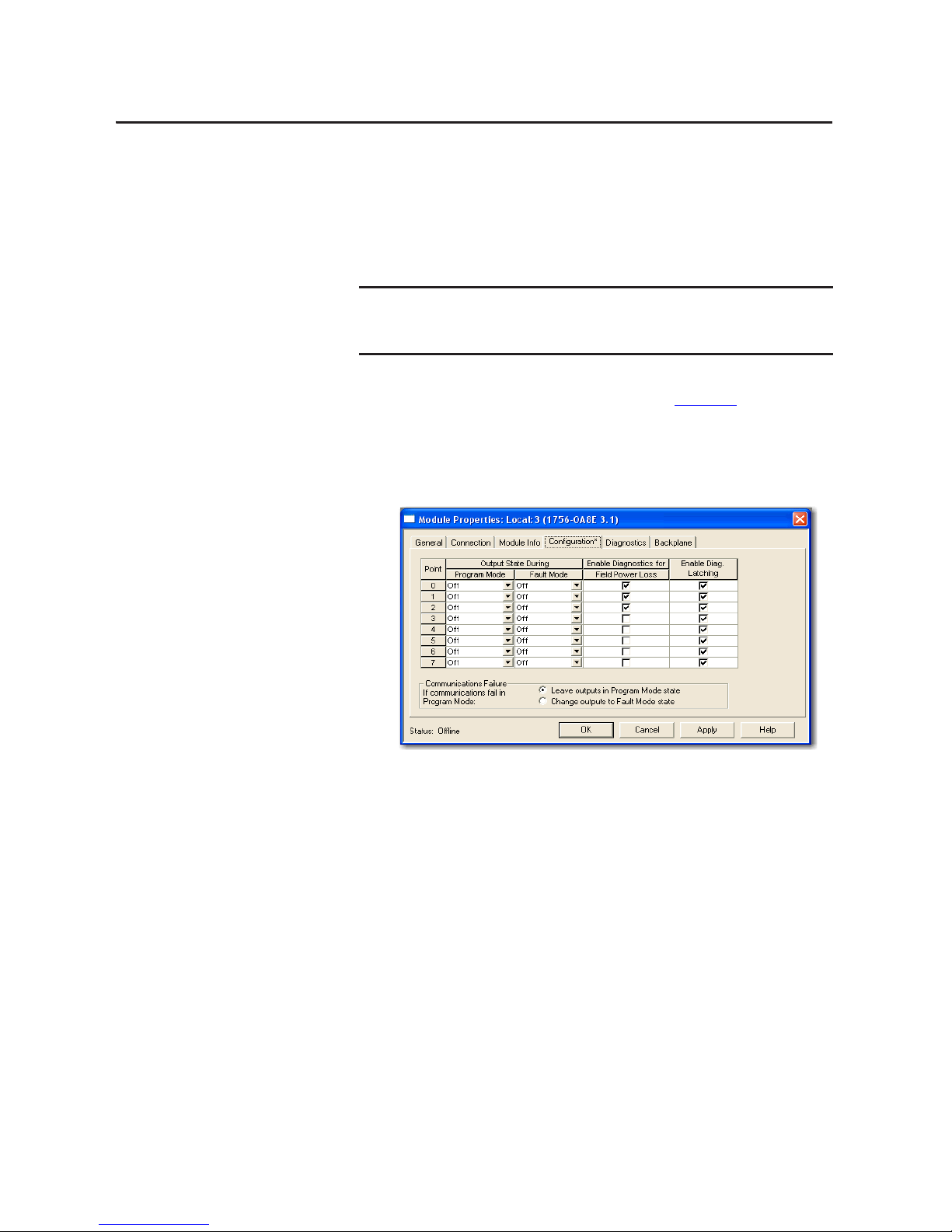
74 Rockwell Automation Publication 1756-UM058G-EN-P - November 2012
Chapter 4 Diagnostic Module Features
Field Power Loss Detection
For the standard digital output modules, the Field Power Loss detection feature is
found on the 1756-IA8D module only. When field power to the module is lost,
or zero cross cannot be detected, a point-level fault is sent to the controller to
identify the exact point faulted.
This feature has a corresponding tag that can be examined in the user program in
the event of a fault. For information on these tags, see Chapter A
.
Follow these steps to enable or disable diagnostics for field power loss.
1. On the Module Properties dialog box, click the Configuration tab.
2. Do one of the following in the Enable Diagnostics for Field Power Loss
column:
• To enable field power loss detection for a specific point, check the
corresponding checkbox.
• To disable field loss detection for a specific point, clear the
corresponding checkbox.
3. Click OK.
IMPORTANT
Only enable Field Power Loss detection for points that are in use. If this feature
is enabled for points that are not in use, you will receive faults for those points
during operation.
Page 75

Rockwell Automation Publication 1756-UM058G-EN-P - November 2012 75
Diagnostic Module Features Chapter 4
Features Specific to
Diagnostic Output Modules
The table below lists features specific to ControlLogix diagnostic digital output
modules.
Field Wiring Options
As with diagnostic input modules, ControlLogix diagnostic output modules
provide isolated or nonisolated wiring options. I/O modules provide point-topoint, group-to-group, or channel-to-channel wiring isolation.
Your specific application determines what type of isolation is necessary and
which output module to use.
No Load Detection
For each output point, no load detection senses the absence of field wiring or a
missing load from each output point in the Off state only.
The output circuit on a diagnostic output module has a current sensing
optoisolator used in parallel with the output transistor. Current flows through
this sensing circuit only when the output is Off, as shown in the simplified
diagram.
Top ic Pag e
Field Wiring Options 75
No Load Detection 75
Field-side Output Verification 76
Pulse Test 78
Diagnostic Change of State for Output Modules 79
IMPORTANT
Although some ControlLogix diagnostic I/O modules provide nonisolated,
field-side wiring options, each I/O module maintains internal electrical
isolation between the system side and field side.
Current
Sense
Load
V+
41681
Output
Tra ns is to r
Current Flow with
Output Off
Current Flow with
Output On
Page 76

76 Rockwell Automation Publication 1756-UM058G-EN-P - November 2012
Chapter 4 Diagnostic Module Features
Diagnostic output modules list a minimum load current specification
(1756-OA8D = 10 mA & 1756-OB16D = 3 mA). In the On state, the module
must be connected to a load that will draw a minimum current equal to these
values.
If a connected load is sized in accordance with the minimum load current
specification, diagnostic output modules are capable of sensing current through
the optoisolator and the load when the output point is Off.
Follow these steps to enable no load detection.
1. On the Module Properties dialog box, click the Configuration tab.
2. Do one of the following in the No Load column:
• To enable the feature for a specific point, check the corresponding
checkbox.
• To disable the feature for a specific point, clear the corresponding
checkbox.
3. Click OK.
This feature has a corresponding tag that can be examined in the user program in
the event of a fault. For more information on these tags, see Appendix
B.
Field-side Output Verification
Field-side output verification informs you that logic-side instructions consumed
by the module are accurately represented on the power side of a switching device.
For each output point, this feature confirms that the output is On when it is
commanded to be On.
The diagnostic output module can tell a controller that it received a command
and whether the field-side device connected to the module has executed the
command. For example, in applications that need to verify that the module has
accurately followed the processor’s instructions, the module samples the field-side
state and compares it to the system-side state.
Page 77

Rockwell Automation Publication 1756-UM058G-EN-P - November 2012 77
Diagnostic Module Features Chapter 4
This feature has a corresponding tag that can be examined in the user program in
the event of a fault. For more information on these tags, see Appendix
B.
If an output cannot be verified, a point-level fault is sent to the controller.
Follow these steps to enable the field-side output verification.
1. On the Module Properties dialog box, click the Configuration tab.
2. Do one of the following in the Output Verify column:
• To enable the feature for a specific point, check the corresponding
checkbox.
• To disable the feature for a specific point, clear the corresponding
checkbox.
3. Click OK.
Page 78

78 Rockwell Automation Publication 1756-UM058G-EN-P - November 2012
Chapter 4 Diagnostic Module Features
Pulse Test
Pulse test is a feature found on diagnostic output modules that can verify outputcircuit functionality without actually changing the state of the output load
device. A short pulse is sent to the targeted output circuit. The circuit should
respond as it would if a real change-of-state command was issued, but the load
device does not transition.
See page 227
in Appendix C for instructions on performing a pulse test with a
CIP Generic Message instruction.
The table explains how a pulse test can be used to perform a preemptive diagnosis
of possible future module conditions.
TIP
Consider the following when using the pulse test:
• Only use the test when the output state does not transition for long periods
of time. Normal diagnostics will catch faults if the outputs are transitioning
regular ly.
• When first performing the pulse test, verify that the load will not
transition. You should be at the actual load while the test is performed.
Objective Pulse Test Description
Detect a blown fuse before it
happens
The Blown Fuse diagnostic can be used only when an output module is in the On
state. However, you can use a pulse test when an output module is in an Off state to
determine whether operating conditions may cause a blown fuse.
When you perform a pulse test on a module in the Off state, the output point is
commanded to be On briefly. Although no diagnostic bits are set in the output data
echo, the pulse test reports a failure if the conditions when the point is On indicate a
blown fuse may occur. See Point-level Fault Reporting
on page 70.
IMPORTANT
The pulse test does not guarantee a fuse will blow
when the output point turns On. It merely indicates a
blown fuse is possible.
Detect a No Load condition
with an output On
No Load detection can only detect a fault when an output point is in the Off state.
However, you can use a pulse test when an output module is in an On state to
determine whether operating conditions for a point may cause a No Load condition.
If you perform a pulse test on an output point while it is in the On state, the output
point is commanded to be Off briefly. The pulse test reports a fail ure because
conditions when the point is Off indicate t he possible absence of a field device; in this
case, though, the No Load bit will not be set. See Point-level Fault Reporting
on
page 70.
IMPORTANT
The Pulse Test does not guarantee the absence of a
load. It merely indicates a No Load condition is
possible.
Page 79

Rockwell Automation Publication 1756-UM058G-EN-P - November 2012 79
Diagnostic Module Features Chapter 4
Diagnostic Change of State for Output Modules
If the Diagnostic Change of State feature is enabled, a diagnostic output module
sends new data to the owner-controller when one of the events described in the
table occurs.
Unlike diagnostic input modules, this feature cannot be disabled for diagnostic
output modules. There is no Enable Change of State for Diagnostic Transitions
checkbox on the Configuration tab to check or clear for diagnostic output
modules.
Fault and Status Reporting
between Input Modules and
Controllers
ControlLogix diagnostic digital input modules multicast fault and status data to
any owner-controller or listening controller. All diagnostic input modules
maintain a module-fault word, the highest level of fault reporting. Some modules
use additional words to indicate fault conditions.
The following table lists the fault words and the associated tags that can be
examined in program logic to indicate when a fault has occurred for a diagnostic
input module.
All words are 32-bit, although only the number of bits appropriate for each
module’s density are used. For example, the 1756-IA16I module has a modulefault word of 32 bits. But, because this is a 16-point module, only the first 16 bits
(0…15) are used in the module-fault word.
Table 11 - Diagnostic Change of State Events
Event Description
Receipt of output data Output module sends data when it echoes back to the owner-controller.
Diagnostic change of state O utput module sends data when any change in the diagnostics output point
occurs.
Table 12 - Fault Words on Diagnostic Input Modules
Word Tag Name Description
Module-fault Fault Provides fault summary reporting. Available on all digital input
modules.
Field Power Loss FieldPwrLoss Indicates loss of field power to a group on the module. Available on
the 1756-IA8D only.
For more information, see Field Power Loss Detection
on page 74.
Open Wire OpenWire Indicates the loss of a wire from a point on the module. For more
information, see Open Wire Detection
on page 73.
Page 80

80 Rockwell Automation Publication 1756-UM058G-EN-P - November 2012
Chapter 4 Diagnostic Module Features
Fault bits in the field-power loss word and open wire word are logically entered
into the module-fault word. Depending on the module type, a bit set in the
module-fault word can mean multiple things, as indicated in the table.
The following illustration provides an overview of the fault reporting process for
digital input modules.
Table 13 - Bits Set in Module-fault Word
Condition Bits Set
Communications fault All 32 bits are set to 1, regardless of the module’s density.
Field-power loss
Only the bit affected is set to 1.
Open wire
Module-fault Word
All modules
Field Power Loss Word
1756-IA8D only
Open Wire Word
Bit 31 Bit 0
An open wire condition on any point sets the bit for that point in the open
wire word and also sets the appropriate bit in the module-fault word.
A loss of field power sets the bit for that group in the field-power loss
word and also sets the appropriate bit in the module-fault word.
A communications fault sets all bits in the module-fault word. A field-power loss
or open wire condition sets the appropriate bit in the module -fault word.
1
1
1
1
Group 0
Group 1
41456
Page 81
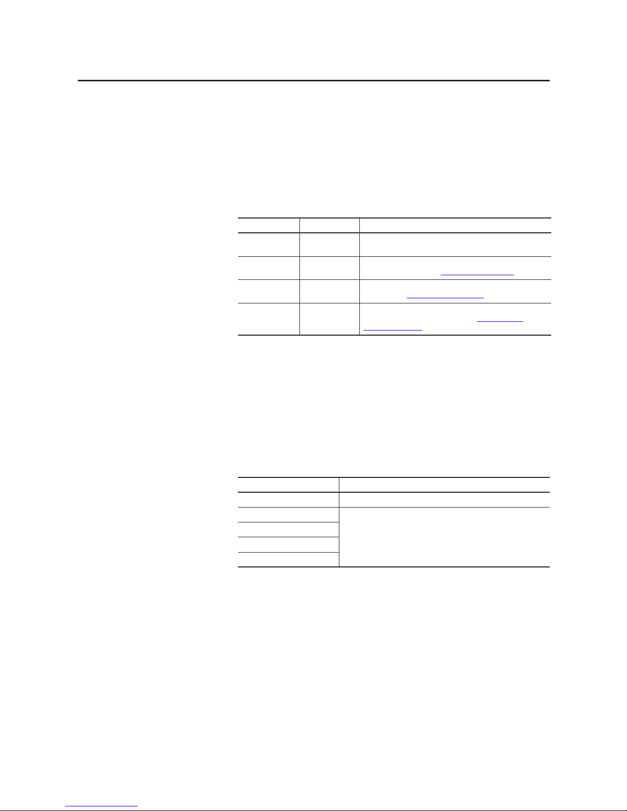
Rockwell Automation Publication 1756-UM058G-EN-P - November 2012 81
Diagnostic Module Features Chapter 4
Fault and Status Reporting
between Output Modules
and Controllers
ControlLogix diagnostic digital output modules multicast fault and status data to
any owner-controller or listening controller. Like input modules, output modules
maintain a module-fault word, the highest level of fault reporting. However,
some output modules use additional words to indicate fault conditions.
The table lists the fault words and the associated tags that can be examined in
program logic to indicate when a fault has occurred for a diagnostic output
module.
All words are 32-bit, although only the number of bits appropriate for each
module’s density are used. For example, the 1756-OB8 module has a modulefault word of 32 bits. But, because the module is an 8-point module, only the first
8 bits (0…7) are used in the module-fault word.
Fault bits in the fuse blown word, field-power loss word, no load word and output
verify word are logically entered into the module-fault word. Depending on the
module type, a bit set in the module-fault word can mean multiple things, as
indicated in the table.
Table 14 - Fault Words on Diagnostic Output Modules
Word Tag Name Description
Module-fault Fault Provides fault summary reporting. Available on all digital output
modules.
Fuse Blown FuseBlown Indicates a blown fuse for a point on the module. For more information,
see For more information, see Electronic Fusing
on page 57.
No Load NoLoad Indicates a loss of a load from a point on the module. For more
information, see No Load Detection
on page 75.
Output Verify OutputVerify Indicates when an output is not performing as commanded by the
owner- controller. For more in formation, see Field-side Output
Verification on page 76.
Table 15 - Bits Set in Module-fault Word
Condition Bits Set
Communication fault All 32 bits are set to 1, regardless of the module’s density.
Fuse bl own
Only the bit affected is set to 1.
Field-power loss
No load
Output verify
Page 82

82 Rockwell Automation Publication 1756-UM058G-EN-P - November 2012
Chapter 4 Diagnostic Module Features
The following illustration provides an overview of the fault reporting process for
digital output modules.
Module-fault Word
Fuse Blown Wor d
Field-power Loss Word
1756-OA8D only
Bit 31 Bit 0
A no load condition for any point sets the bit for that point in the no
load word and also sets the appropriate bit in the module-fault word.
A blown fuse for any point sets the bit for that point in the fuse blown word and
also sets the appropriate bits in the module-fault word.
A communications fault sets all bits in the module-fault word. A fuse blown,
field-power loss, no load or output verify condition sets the appropriate bit in
the module-fault word.
No Load Word
Output Verify Word
A loss of field power from any group sets the bit for that point in the field-power
loss word and also sets the appropriate bits in the module-fault word.
An output verify condition for any point sets the bit for that point in the output
verify word and also sets the appropriate bit in the module-fault word.
1
Group 0
1
1
1
1
1
Group 1
1
1
41457
Page 83

Rockwell Automation Publication 1756-UM058G-EN-P - November 2012 83
Chapter 5
Fast Module Features
Fast digital I/O modules provide quick response time for high-speed control
applications. The table lists the available fast digital I/O modules.
Fast Input Module
Compatibility
When designing systems with ControlLogix fast input modules, consider these
factors:
• Voltage necessary for your application
• Sensor performance and specifications
• Whether your application should use sinking or sourcing wiring
Top ic Pag e
Fast Input Module Compatibility 83
Fast Output Module Compatibility 84
Fast Feat ures 84
Features Specific to Fast Input Modules 85
Features Specific to Fast Output Modules 95
Fault and Status Reporting between Input Modules and Controllers 106
Fault and Status Reporting between Output Modules and Controllers 107
Cat. No. Description
1756-IB16IF 10…30V DC,16-point, isolated, fast peer control input module
1756-OB16IEF 10…30V DC,16-point, isolated, fast peer control output module
1756-OB16IEFS 10…30V DC, 16-point, isolated, fast, scheduled per point output module
Page 84

84 Rockwell Automation Publication 1756-UM058G-EN-P - November 2012
Chapter 5 Fast Module Features
Fast Output Module
Compatibility
ControlLogix fast output modules can be used to drive a variety of output
devices. Typical output devices compatible with ControlLogix outputs include
these items:
• Solenoids
• Indicators
Follow these guidelines when designing a system:
• Make sure that the ControlLogix outputs can supply the necessary surge
and continuous current for proper operation.
• Make sure that the surge and continuous current are not exceeded.
Damage to the module could result.
When sizing output loads, refer to the documentation supplied with the output
device for the surge and continuous current needed to operate the device.
Outputs on fast output modules can be directly wired to inputs on fast input
modules.
Fast Features
Module features include all the common features described in Chapter 3, as well
the extended capabilities described within this chapter.
For higher-speed control, the 1756-OB16IEF output module can be configured
to receive input status over the backplane directly from the 1756-IB16IF input
module or 1756-LSC8XIB8I counter module without controller processing.
This feature, know as peer ownership, is described in the ControlLogix Peer
Ownership Application Technique, publication 1756-AT016
.
IMPORTANT
To configure the modules, you must have the following:
• The 1756-OB16IEF module requires RSLogix 5000 software, version
18.02.00 or later or Studio 5000 environment, version 21.00.00 or later.
• The 1756-OB16IEFS module requires Studio 5000 environment, version
21.00.00 or later.
• The Add-on Profile (AOP) for each module available for download at
http://support.rockwellautomation.com/controlflash/LogixProfiler.asp
.
Page 85

Rockwell Automation Publication 1756-UM058G-EN-P - November 2012 85
Fast Modu le Fea tures Chapter 5
Response Time
The tables below indicate the screw-to-backplane response time of fast input and
fast output modules.
Features Specific to
Fast Input Modules
The table below lists features specific to ControlLogix fast digital input modules.
Table 16 - Input Response Time
Delay Respons e Time
Total On/Off delay (screw to backplane) 14 s nom/23 s max + user-configurable filter time
Hardware delay < 1 µs nom, 2 µs max
Firmware delay 13 µs nom, 21 µs max
User-configurable filter time 0…30,000 µs
Table 17 - Output Response Time
Delay Respons e Time
Total On/Off delay (screw to backplane) 14 s nom/23 s max
Hardware delay < 1 µs nom, 2 µs max
Firmware delay 13 µs nom, 21 µs max
Top ic Page
Pulse Capt ure 86
Per Point Timestamping and Change of State 87
Software Configurable Filter Times 90
Dedicated Connection for Event Tasks 93
IMPORTANT
In RSLogix 5000 software, version 18.02.00 and 19.01.00, output tag
information is sent to the 1756-IB16IF module only at the RPI rate defined
during configuration. For optimal performance, use an Immediate Output (IOT)
instruction.
For example, the rung shown below contains an IOT instruction for a fast input
module in slot 3. Add a similar rung to your last routine within the Main Task to
mimic normal output tag processing.
Page 86

86 Rockwell Automation Publication 1756-UM058G-EN-P - November 2012
Chapter 5 Fast Module Features
Pulse Capture
The 1756-IB16IF fast input module can be used to detect or latch short duration
pulses. The module can detect incoming pulses with a duration as short as 10 µs if
the frequency is under 4 kHz (period of 250 µs).
When the module detects a short duration pulse at an input point, it sets the
corresponding bit for the Pt[x].NewDataOffOn or Pt[x].NewDataOnOff input
tag. This bit remains latched until acknowledged. As a result, you can use this bit
to detect a transition that is too fast to be detected by the program scan. You can
also determine how rapid the transition was by configuring the module to latch
timestamps for the point, as described in Per Point Timestamping and Change of
State on page 87.
To acknowledge the last captured pulse and reset the pulse latch, you set the rising
edge of the corresponding bit in these output tags:
• Pt[x].NewDataOffOnAck—Acknowledges that the input point has
transitioned to an On state and resets the pulse latch.
• Pt[x].NewDataOnOffAck—Acknowledges that the input point has
transitioned to an Off state and resets the pulse latch.
You can change output tag values in program logic while normal module
operation continues or through the RSLogix 5000 tag editor. For more
information about module tags, refer to Appendix
B.
Once a pulse latch is reset for an input point, the next pulse at that point sets the
corresponding bit in the Pt[x].NewDataOffOn or Pt[x].NewDataOnOff input
tags.
Page 87

Rockwell Automation Publication 1756-UM058G-EN-P - November 2012 87
Fast Modu le Fea tures Chapter 5
Per Point Timestamping and Change of State
With per point timestamping, each input point on the module records
timestamps in CIP Sync format at these speeds:
• ± 4 µs for inputs < 4 kHz
• ± 13 µs for inputs > 4 kHz
You can configure an input point to record a timestamp when the point
transitions from On to Off, Off to On, or in both directions. By default, all
points are configured to record a timestamp in both directions.
You can also configure the module to latch timestamps for an input point’s last
transition. When latching is enabled for a specific point, the point records a
timestamp in the Pt[x].Timestamp.OffOn or Pt[x].Timestamp.OnOff input
tags. The timestamp remains latched, and no new timestamps are recorded for
the input point until the timestamp is acknowledged and reset. As a result, you
can use the timestamp to determine the speed of a transition that is too fast to be
detected by the program scan.
To acknowledge a transition and reset a timestamp latch, you set the
corresponding bit in these output tags:
• Pt[x].NewDataOffOnAck—Acknowledges that the input point has
transitioned to an On state and resets the timestamp latch.
• Pt[x].NewDataOnOffAck—Acknowledges that the input point has
transitioned to an Off state and resets the timestamp latch.
The Pt[x].TimestampDropped input tag indicates whether a new timestamp has
not been recorded because a previous timestamp was either latched or
unacknowledged.
Once a timestamp latch is reset for an input point, a new timestamp may be
recorded in the Pt[x].Timestamp.OffOn or Pt[x].Timestamp.OnOff input tags
upon the next transition.
You can configure per point timestamping in three ways:
• Timestamping enabled without latching (default configuration)
• Timestamping enabled with latching
• Timestamping disabled
IMPORTANT
Timestamping functions only in a CIP Sync system. If you are using change of
state (COS) in a system using Coordinated System Time (CST), all timestamp
values and the GrandMasterClockID input tag are set to zero.
To set up CIP Sync time synchronization on the local controller, use the
Date/Time tab in the controller properties. For more information about CIP
Sync configuration, refer to the Integrated Architecture and CIP Sync
Configuration Application Technique, publication IA-AT003
.
Page 88

88 Rockwell Automation Publication 1756-UM058G-EN-P - November 2012
Chapter 5 Fast Module Features
Follow these steps to configure per point timestamping and enable COS.
1. On the New Module dialog box, click Change to display the Module
Definition dialog box.
2. Use the table below to choose a connection format and input data type
from the Connection and Input Data pull-down menus.
IMPORTANT
To enable timestamping, choose Timestamp Data as the input data type.
Connection Format Input Data Data Return
Data Timestamp Data Module returns input data with COS timestamps in CIP Sync system
time.
Data Module returns input data without COS timestamps. This format is
useful when the highest possible throughp ut is required, and
timestamps are not required.
Data with Event Timestamp Data Results in two input connections:
• Connection to return input data with COS timestamps in CIP Sync
system time.
• Connection to initiate event tasks. See page 93
.
Listen Only Timestamp Data These formats have the same definition as those above except that
they are Listen-only connections.
Data
Listen Only with Event Timestamp Data
TIP
You can change the connection format at any time after creating a new
module except when you are online. The AOP will apply all the configuration
data and create the tags required for the new connection format.
Opens the Module Definition dialog box.
Page 89

Rockwell Automation Publication 1756-UM058G-EN-P - November 2012 89
Fast Modu le Fea tures Chapter 5
3. On the New Module or Module Properties dialog box, click the
Configuration tab.
Timestamp fields only appear on the Configuration tab when you choose
Timestamp Data from the Input Data pull-down menu on the Module
Definition dialog box.
4. Complete the fields as described in the table below and click OK.
5. If you checked the Latch Timestamps checkbox, use program logic or the
RSLogix 5000 tag editor to acknowledge transitions and clear latched
timestamps via the Pt[x].NewDataOffOnAck and
Pt[x].NewDataOnOffAck output tags.
For more information about module tags, refer to Appendix
B.
Field Description Configuration Tag
Enable COS/Timestamps
Off
On
To enable COS and timestamping for an Off to On transition for a
point, check the corresponding checkbox.
To disable COS and timestamping for an Off to On transition for a
point, clear the corresponding checkbox.
Pt[x].COSOffOnEn
Enable COS/Timestamps
On
Off
To enable COS and timestamping for an On to Off transition for a
point, check the corresponding checkbox.
To disable COS and timestamping for an On to Off transition for a
point, clear the corresponding checkbox.
Pt[x].COSOnOffEn
Latch Timestamps Check the checkbox to latch a CIP Sync timestamp for a COS
transition:
• When an initial timestamp is latched, timestamps fo r
subsequent COS transitions are dropped.
• Once a latched timestamp is acknowledged via the
corresponding bit in the Pt[x].NewDataOffOnAck or
Pt[x].NewDataOnOffAck tag, the timestamp is overridden
upon the next COS transition.
IMPORTANT: Timestamps are latched only for points that are
enabled for COS and timestamping.
LatchTimestamps
Page 90

90 Rockwell Automation Publication 1756-UM058G-EN-P - November 2012
Chapter 5 Fast Module Features
Software Configurable Filter Times
To account for hard contact bounce, you can configure Off to On and On to Off
input filter times of 0…30, 000 µs in RSLogix 5000 software. These filters define
how long an input transition must remain in the new state before the module
considers the transition valid.
When an input transition occurs, the module timestamps the transition on the
edge of the transition and stores timestamp data for the transition. The module
then monitors the input for the duration of the filter time to verify that the input
remains in the new state:
• If the input remains in the new state for a time period equal to the filter
time, the input is recognized and recorded. The module sends timestamp
data for the transition and the input’s On/Off state to the controller.
• If the input changes state again before the duration of the filter time has
elapsed, the module continues to scan that input for up to 10x
the filter
time. During this continued scan period, one of the following events
occurs:
– In the time period that is 10x the duration of the filter time, the input
returns to the transitioned state for the duration of the filter time. In
this case, the module sends timestamp data from the initial transition to
the controller.
– In the time period that is 10x the duration of the filter time, the input
never remains in the transitioned state for the duration of the filter
time. In this case, the input is recognized, but the module does not
consider the original transition valid and drops the timestamp.
EXAMPLE
A 1756-IB16IF module is configured for a 2 ms filter time for Off to On
transitions. In this example, three possible scenarios can result after an input
transitions from Off to On:
•Scenario 1—The input turns On and remains On for the full 2 ms filter
time. The module considers the transition valid and sends the data
recorded at the transition to the controller (Figure 9 on page 91
).
•Scenario 2—The input turns On but turns Off before the 2 ms filter time
elapses. The module continues to monitor the input for 10x the duration of
the filter time. Within that time period, the input turns On again and
remains On for at least 2 ms. The module considers the transition valid and
sends the data timestamped at the original transition to the controller
(Figure 10 on page 91
).
•Scenario 3—The input turns On but turns Off before the 2 ms filter time
elapses. The module continues to monitor the input for 10x the duration of
the filter time. Within that time period, the input never remains On for at
least 2 ms. The module considers the transition invalid and drops the data
timestamped at the original transition (Figure 11 on page 91
).
Page 91
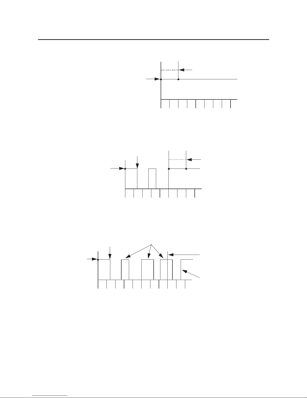
Rockwell Automation Publication 1756-UM058G-EN-P - November 2012 91
Fast Modu le Fea tures Chapter 5
Figure 9 - Valid Transition with No Bounce
Figure 10 - Transition Valid with Bounce
Figure 11 - Invalid Transition
012345678
Input turns On, and a
timestamp is recorded.
Time in milliseconds
Input remains On for at least 2 ms. The transition is
considered valid, and the timestamp is sent to the controller.
012345678
Time in milliseconds
Input turns On and remains On for at least 2 ms in the
20 ms time period that is 10x the input filter time.
The module sends the timestamp recorded at the
original transition point (time 0) to the controller.
Input turns Off before 2 ms elapses.
Input turns On, and a
timestamp is recorded.
012341718 19 20
Time in m illiseconds
Input turns Off before 2 ms elapses.
The input never remains
On for at least 2 ms.
After the 20 ms time period that is 10x the input filter
time, the module drops the data recorded at the
original transition. If an RPI occurs during this time,
the module sends the controller its current valid input
data. The data that is sent does not include data from
the transition because the input transition has not
cleared the filter and been recognized as a valid input.
Input turns On, and a
timestamp is recorded.
The next time the input turns On, the module
records the transition as timestamp 21.6 once
the input passes the filter time.
…
21
22
Page 92

92 Rockwell Automation Publication 1756-UM058G-EN-P - November 2012
Chapter 5 Fast Module Features
Follow these steps to configure input filter times.
1. On the Module Properties dialog box, click the Configuration tab.
2. In the Input Filter Time column, enter Off to On and On to Off input
filter times from 0…30,000 µs and click OK.
3. Complete the fields as described in the table below and click OK.
Field Description Configuration Tag
Enable Filter To enable filtering for a point, check the corresponding checkbox.
To disable filtering for a point, clear the corresponding checkbox.
Pt[x].FilterEn
Input Filter Time
Off
On
Enter an Off to On input filter time from 0…30,000 µs. FilterOffOn
Input Filter Time
On
Off
Enter an On to Off input filter time from 0…30,000 µs. FilterOnOff
Page 93

Rockwell Automation Publication 1756-UM058G-EN-P - November 2012 93
Fast Modu le Fea tures Chapter 5
Dedicated Connection for Event Tasks
The 1756-IB16IF input module can initiate an event task over a dedicated
second connection in response to four user-defined input patterns. You can
define these patterns in real time during a control process by using these output
tags:
• Event[x].Mask—Defines which input points trigger the event task.
• Event[x].Value—Defines whether the masked input points must be in the
On or Off state before the event task is triggered.
Each pattern can use any of the module’s 16 input points, as shown in the
examples below.
In example pattern 1, the input module triggers the event task when input points
0…7 are in the On state.
In example pattern 2, the input module triggers the event task when input points
0…7 are in the Off state.
In example pattern 3, the input module triggers the event task when input points
4, 6, 8, and 10 are in the On state.
Table 18 - Example Pattern 1
Output Tag Bit Position
0123456789101112131415
Event[x].Mask 1111111100000000
Event[x].Value 11111111xxx xxxxx
Table 19 - Example Pattern 2
Output Tag Bit Position
0123456789101112131415
Event[x].Mask 1111111100000000
Event[x].Value 00000000xx xx xxxx
Table 20 - Example Pattern 3
Output Tag Bit Position
0123456789101112131415
Event[x].Mask 0000101010100000
Event[x].Value xxxx1x1x1x1xxxxx
Page 94
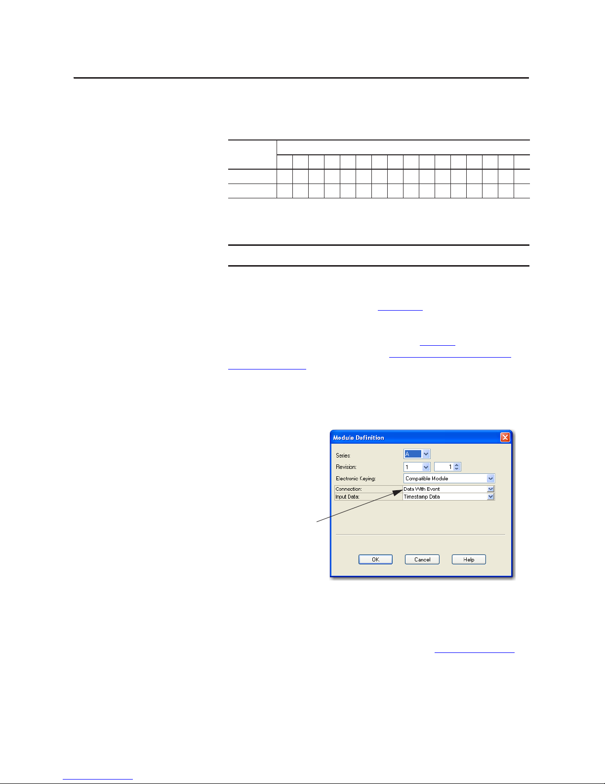
94 Rockwell Automation Publication 1756-UM058G-EN-P - November 2012
Chapter 5 Fast Module Features
In example pattern 4, the input module triggers the event task when input points
0…3 are in the On state, and input points 12…15 are in the Off state.
Once you define a pattern, you can disable an event from being triggered without
clearing its output data by using the Event[x].Disarm output tag.
You can change output tag values in program logic while normal module
operation continues or through the RSLogix 5000 tag editor. For more
information about module tags, refer to Appendix
B.
To use a dedicated connection to trigger event tasks, you must set the module’s
connection format to Data with Event, as shown in Figure 12
. For more
information about connection formats, see Communication or Connection
Formats on page 131.
Figure 12 - Event Connection Format
When you choose the Data with Event connection format, the following occurs:
• A second connection dedicated to event data only is established with the
module. This dedicated event connection reduces controller overhead
when using inputs or input patterns to trigger event tasks in the controller.
• A new set of event tags is created, as described in Table 46 on page 193
.
Table 21 - Example Pattern 4
Output Tag Bit Position
0123456789101112131415
Event[x].Mask 1111000000001111
Event[x].Value 1111xxxxxx xx0000
IMPORTANT
All event masks and event values must be defined in the module’s output tags.
TIP
You can change the connection format at any time after creating a new
module except when you are online. The AOP will apply all the
configuration data required for the new connection format.
Choose Data with Event from the
Connection pull-down menu.
Page 95
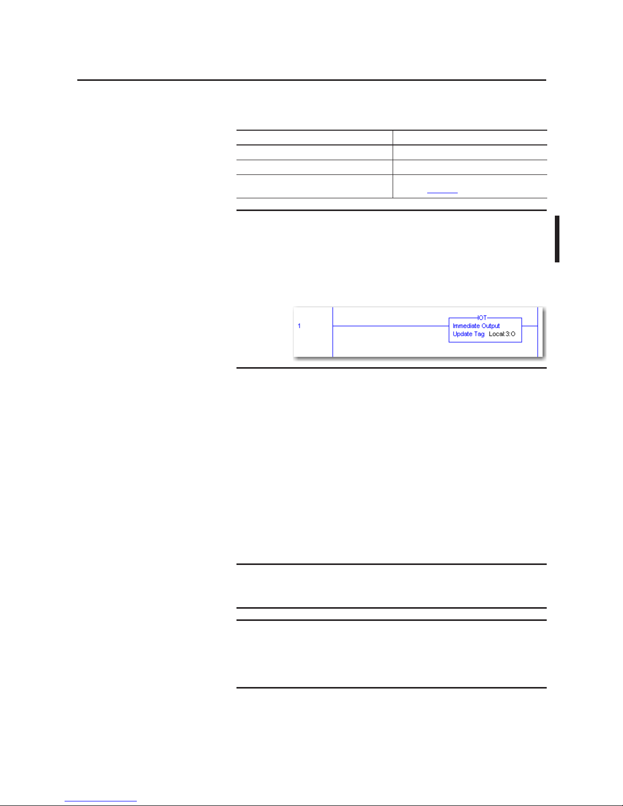
Rockwell Automation Publication 1756-UM058G-EN-P - November 2012 95
Fast Modu le Fea tures Chapter 5
Features Specific to
Fast Output Modules
The table below lists features specific to ControlLogix fast digital output
modules.
Programmable Fault State Delays
You can define the following states for an output point that is in Fault mode due
to a communication failure:
• Duration—Defines the length of time that the output remains in the Fault
mode state before transitioning to a final state of On or Off. By default, the
output remains in the Fault mode state as long as the fault condition
persists.
• Final state—Defines whether the output transitions to the On or Off state
after the duration of the Fault mode state elapses. By default, the output
transitions to the Off state.
Top ic Pa ge
Programmable Fault State Delays 95
Pulse Width Modulation 97
Peer I/O Control (1756-OB16IEF only) See the Peer I/O Control Application Technique,
publication 1756-AT016
IMPORTANT
In RSLogix 5000 software, version 18.02.00 and 19.01.00, output tag
information is sent to the 1756-OB16IEF module only at the RPI rate defined
during configuration. For optimal performance, use an Immediate Output (IOT)
instruction.
For example, the rung shown below contains an IOT instruction for a fast
output module in slot 3. Add a similar rung to your last routine within the Main
Task to mimic normal output tag processing.
EXAMPLE
You define a duratio n of 1 sec ond and a final s tate of O n for an o utput po int. If a
fault occurs at that point, the output remains in its Fault mode state (O ff, On, or
Hold) for 1 second before transitioning to the On state.
IMPORTANT
If a connection is reestablished after an output point goes into Fault mode but
before the duration time elapses, the settings you specify for the duration and
final state no longer apply. For example, if you specify a 10 second duration and
a final state of Off, and the fault ends in 3 seconds, the output point never
transitions to the final state of Off.
Page 96

96 Rockwell Automation Publication 1756-UM058G-EN-P - November 2012
Chapter 5 Fast Module Features
For more information about defining a Fault mode state, refer to Configurable
Point-level Output States on page 55.
Follow these steps to configure a fault state delay.
1. On the Module Properties dialog box, click the Output State tab.
2. Complete the fields as described in the table below and click OK.
Field Description 1756-OB16IEF
Configuration Tag
1756-OB16IEFS
Configuration Tag
Fault Mode Output State
Duration
Choose the length of time you want the output to remain in Fault mode state
before transitioning to the final state:
• 1 second
• 2 seconds
• 5 seconds
• 10 seconds
• Forever (de fault)
IMPORTANT: If you choose Forever, the output will remain in the Fa ult mode
state until a connection is reestablished. For example, if the Fault mode is Hold,
and you specify a duration of Forever, then the output retains its Hold state and
does not transition to a Final state if a fault occurs.
Pt[x].FaultValueStateDuration FaultValueStateDuration
Fault Mode Output State
Final State
Choose whether you want the module to transition to an On or Off state after the
Fault mode duration time elapses.
The default final state is Off. If you chose Forever, you cannot choose a final state.
The module will retain its current Fault mode state.
Pt[x].FaultFinalState FaultFinalState
Page 97

Rockwell Automation Publication 1756-UM058G-EN-P - November 2012 97
Fast Modu le Fea tures Chapter 5
Pulse Width Modulation
Pulse Width Modulation (PWM) provides precise, onboard control of an
output’s pulse train with no program variability. To configure a PWM signal, you
define two real-time values for the pulse train in the module’s output tags:
• Cycle time—The duration of a pulse cycle in seconds from 1 ms…1 hour.
• On time—The pulse width, or length of time that a pulse is active within a
cycle from 200 µs…1 hour. You can define the On time in seconds or as
0…100 percent of the cycle time. You may want to use a steady-state On
time, such as for gluing applications, or a dynamic On time that is defined
by program logic.
If the cycle time or On time is outside the valid range for an output, the
corresponding bit in the Fault input tag is set and the module responds as
described below.
If the cycle time or On time value changes while the output is generating a PWM
signal, the changes are not applied until the next cycle of the PWM output. For
instance, if the cycle time is erroneously set to an hour, a new cycle time will not
go into effect until the last cycle of the hour is complete. To trigger the PWM
output to restart immediately with a new cycle time or On time, turn the output
Off and then back On.
Condition Result
PWMCycleTime <
minimum of 1ms PWMCycleTime = 1 ms
PWMCycleTime > maximum of 1 hour PWMCycleTime = 1 hour
PWMCycleTime
≤ PWMOnTime Output is always On
PWMOnTime < minimum of 200 µs Out put is always Off
PWMOnTime > maximum of 1 hour PWMOnTime = 1 hour
EXAMPLE
If PWMOnTime is 0.1 second and PWMCycleTime is 1.0 second and the
PWMCycleTime is changed to 0.5 second just after the output turns On, the
output will stay on for 0.1 second and then turn Off for 0.9 second to complete
the cycle before the new 0.5 second cycle begins.
IMPORTANT
Before PWM will function, you must enable PWM during configuration and
define the PWM cycle time and On time in the PWMCycleTime and
PWMOnTime output tags.
If PWM is enabled (PWMEnable = 1) and the output is instructed to turn On
(Data = 1), the output generates a PWM signal.
Page 98

98 Rockwell Automation Publication 1756-UM058G-EN-P - November 2012
Chapter 5 Fast Module Features
Figure 13 compares two applications in which the output is instructed to turn
On for 4.5 seconds:
• In the application without PWM, a single pulse is generated. The pulse
remains active for the same length of time the Data output tag is On
(4.5 seconds).
• In the application with PWM, a series of pulses are generated. Each pulse is
active for a configured On time of .5 seconds or 50% of the 1 second cycle
time. The Data output tag is On for 4.5 seconds.
Figure 13 - PWM
By default, PWM is configured to continue the output pulse train until the
output logic turns Off. When the output logic turns Off, the output pulse train
immediately stops.
Figure 14 - PWM with Truncated Pulse
Output Logic
Output State
Output logic is On for 4.5 seconds.
Output is active for 4.5 seconds.
Output Logic
Output State
Output logic is On for 4.5 seconds.
Each pulse is active for 0.5 seconds (On time)
Application without PWM
Application with PWM
1 Second
Cycl e Time
EXAMPLE
In Figure 14, the output logic is On for 4.25 seconds and then turns Off in the
middle of the last pulse. Even though the PWM On time is configured for 0.5
seconds, the last pulse is only active for 0.25 seconds because it is truncated
when the output logic turns Off.
Output Logic
Output State
Output logic is On for 4.25 seconds.
The last pulse is truncated when the output logic turns Off.
Page 99

Rockwell Automation Publication 1756-UM058G-EN-P - November 2012 99
Fast Modu le Fea tures Chapter 5
You can modify the default PWM configuration for each of a module’s 16
outputs for further control of an output’s pulse train, as described in PWM
Configuration on page 103. Configuration options include the following:
• Cycle Limit and Execute All Cycles, as described below
• Minimum On Time, Extend Cycle, and Stagger Output as described on
page 100
Cycle Limit and Execute All Cycles
You can limit the number of pulse cycles that occur while an output is On. This
feature is useful when you want to apply a level of output control when a process
is stopped. For example, in a gluing application, you may want to apply 4 drops of
glue to a product when the product is within a fixed window on a conveyor belt.
By configuring a cycle limit of 4, you can make sure that only 4 drops of glue are
applied even if the conveyor belt stops with the product in the window.
Controlling the process with the Cycle Limit feature eliminates the need to write
complex logic to detect a stopped conveyor belt.
Figure 15
shows a PWM pulse train configured with a cycle limit of 2. The
PWMCycleLimitDone input tag indicates when the PWM cycle limit has been
reached. The corresponding bit is reset upon the next rising edge of the output
which restarts PWM.
Figure 15 - PWM Cycle Limit
IMPORTANT
The Program and Fault mode states configured for the module override the
PWM output state unless the point is configured to hold the last state while in
Program or Fault mode. If a point is configured to hold the last state and the
output is currently On, the output will continue to use PWM until the PWM
cycle limit is reached, the module transitions out of Program or Fault mode, or
a final fault state goes into effect.
For more information, see the following:
• Configurable Point-level Output States
on page 55
• Programmable Fault State Delays on page 95
• Cycle Limit and Execute All Cycles on page 99
Output Logic
Only 2 cycles are executed even
though the output logic remains On.
Output State
The cycle limit restarts when the output begins pulsing
on the next rising edge of output logic.
Page 100
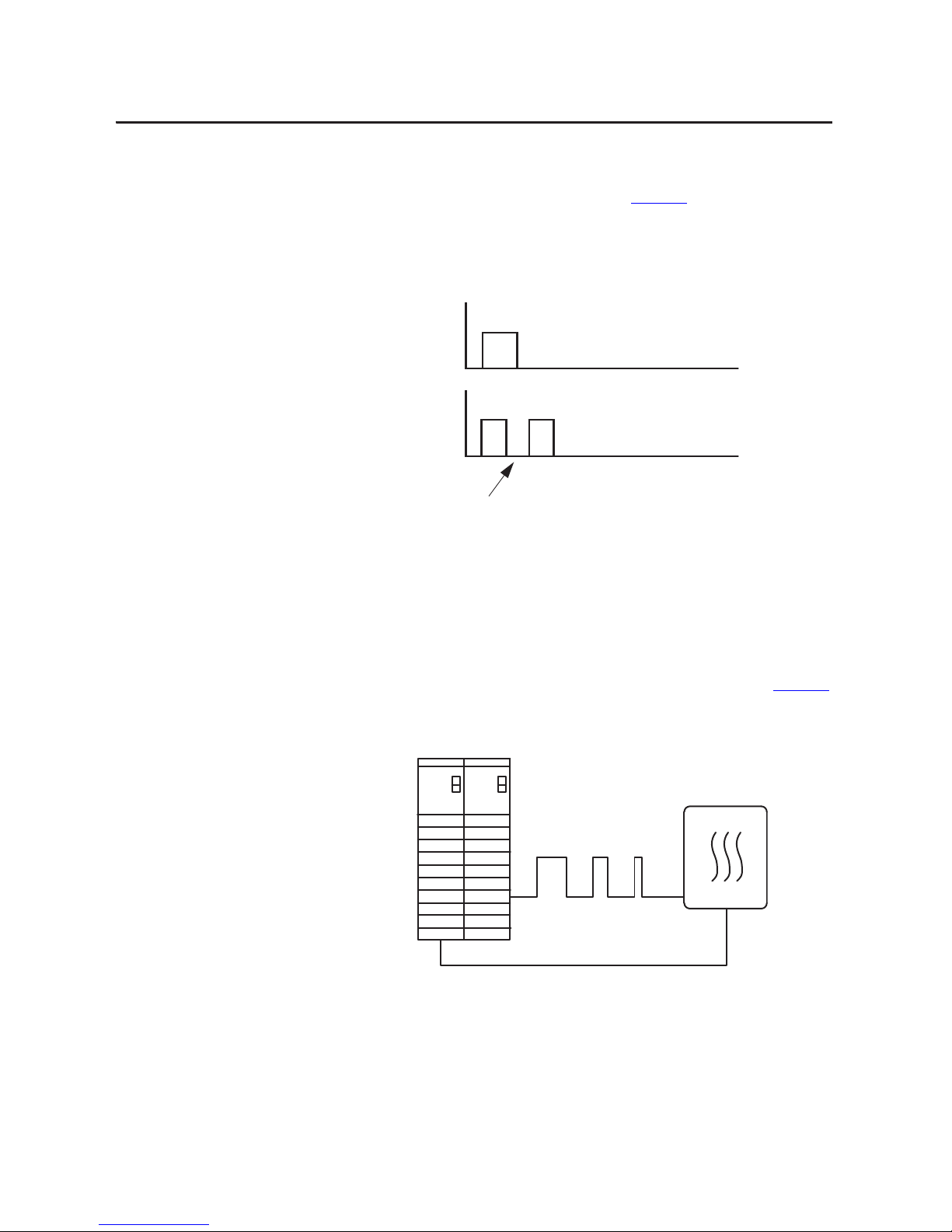
100 Rockwell Automation Publication 1756-UM058G-EN-P - November 2012
Chapter 5 Fast Module Features
If the output logic turns Off before the cycle limit is reached, you can
configure the pulse cycles to continue until the cycle limit is reached by
enabling the Execute All Cycles option. Figure 16
shows a cycle limit of 2
with the Execute All Cycles option enabled.
Figure 16 - PWM Cycle Limit with Execute All Cycles Option
Minimum On Time, Extend Cycle, and Stagger Output
The Minimum On Time, Extend Cycle, and Stagger Output configuration
options are useful in time-proportional control applications, such as temperature
control. In these applications, PID calculations compare the actual temperature
to the desired setpoint and vary the PWM On time to a heating element in real
time to regulate temperature as it approaches the setpoint, as shown in Figure 17
.
Figure 17 - PWM for Time Proportioned Control
Output Logic
Both cycles are executed even though the output
logic turned Off before the cycle limit was reached.
Output State
Heated Vessel
Variable PWM On Time
from PID Calculation
Temperature Feedback to Analog Input
 Loading...