

Page 1
ProcessLogix
Function Blocks
1757 Series
Reference Manual
Spare Allen-Bradley Parts
Page 2

Page 3

Important User Information
Because of the variety of uses for the products described in this
publication, those responsible for the application and use of these
products must satisfy themselves that all necessary steps have been
taken to assure that each application and use meets all performance
and safety requirements, including any applicable laws, regulations,
codes and standards. In no event will Allen-Bradley be responsible
or liable for indirect or consequential damage resulting from the use
or application of these products.
Any illustrations, charts, sample programs, and layout examples
shown in this publication are intended solely for purposes of
example. Since there are many variables and requirements associated
with any particular installation, Allen-Bradley does not assume
responsibility or liability (to include intellectual property liability) for
actual use based upon the examples shown in this publication.
Allen-Bradley publication SGI-1.1, Safety Guidelines for the
Application, Installation and Maintenance of Solid-State Control
(available from your local Allen-Bradley office), describes some
important differences between solid-state equipment and
electromechanical devices that should be taken into consideration
when applying products such as those described in this publication.
Reproduction of the contents of this copyrighted publication, in
whole or part, without written permission of Rockwell Automation, is
prohibited.
Throughout this publication, notes may be used to make you aware
of safety considerations. The following annotations and their
accompanying statements help you to identify a potential hazard,
avoid a potential hazard, and recognize the consequences of a
potential hazard:
WARNING
Identifies information about practices or
circumstances that can cause an explosion in a
hazardous environment, which may lead to personal
injury or death, property damage, or economic loss.
!
ATTENTION
Identifies information about practices or
circumstances that can lead to personal injury or
death, property damage, or economic loss.
!
IMPORTANT
Identifies information that is critical for successful
application and understanding of the product.
Allen-Bradley is a trademark of Rockwell Automation
Spare Allen-Bradley Parts
Page 4

Rockwell Automation Support
Rockwell Automation offers support services worldwide, with over 75
sales/support offices, 512 authorized distributors, and 260 authorized
systems integrators located throughout the United States alone, plus
Rockwell Automation representatives in every major country in the
world.
Local Product Support
Contact your local Rockwell Automation representative for:
• sales and order support
• product technical training
• warranty support
• support service agreements
Technical Product Assistance
If you need to contact Rockwell Automation for technical assistance,
first call your local Rockwell Automation representative, then:
• Technical Support, 440.646.5800
• Web Links, http://www.ab.com
Your Questions or Comments on this Manual
If you find a problem with this manual, please notify us of it on the
How Are We Doing? form at the back of this manual.
Page 5

Introduction to Control Builder
Components
Table of Contents
Important User Information . . . . . . . . . . . . . . . . . . . . . . . . . iii
Rockwell Automation Support . . . . . . . . . . . . . . . . . . . . . . . iv
Local Product Support . . . . . . . . . . . . . . . . . . . . . . . . . . iv
Technical Product Assistance . . . . . . . . . . . . . . . . . . . . . iv
Your Questions or Comments on this Manual . . . . . . . . . iv
Chapter 1
Component Categories and Types . . . . . . . . . . . . . . . . . . . 1-1
Hardware relation category . . . . . . . . . . . . . . . . . . . . . 1-1
Functional relation category . . . . . . . . . . . . . . . . . . . . . 1-5
Component Libraries . . . . . . . . . . . . . . . . . . . . . . . . . . . . . 1-7
System (SYSTEM) Library . . . . . . . . . . . . . . . . . . . . . . . 1-7
Auxiliary (AUXILIARY) Library . . . . . . . . . . . . . . . . . . . 1-7
Device Control (DEVCTL) Library . . . . . . . . . . . . . . . . . 1-7
Data Acquisition (DATAACQ) Library . . . . . . . . . . . . . . 1-7
Input/Output Module (IO) Library . . . . . . . . . . . . . . . . 1-8
Input/Output Channel (IOCHANNEL) Library . . . . . . . . 1-9
Logic (LOGIC) Library . . . . . . . . . . . . . . . . . . . . . . . . . 1-9
Regulatory Control (REGCTL) library. . . . . . . . . . . . . . . 1-10
Sequential Control Module (SCM) library . . . . . . . . . . . 1-10
Utility (UTILITY) Library. . . . . . . . . . . . . . . . . . . . . . . . 1-10
ControlNet Interoperability (Exchange) Library . . . . . . . 1-11
Pulse Input Channel/Module (PULSEINPUT) Library . . . 1-11
1797 FLEX Ex Modules (RAIL_IO_HAZ) . . . . . . . . . . . . 1-11
Profibus Interface (PBUSIF) Library. . . . . . . . . . . . . . . . 1-11
1794 FLEX I/O Modules (RAIL_IO) . . . . . . . . . . . . . . . . 1-12
Fieldbus Interface (FBUSIF) Library . . . . . . . . . . . . . . . 1-12
Chapter 2
Physical Equipment Blocks
Overview . . . . . . . . . . . . . . . . . . . . . . . . . . . . . . . . . . . . . 2-1
Control Processor Module (CPM) . . . . . . . . . . . . . . . . . 2-1
Control Execution Environment (CEE) . . . . . . . . . . . . . 2-2
Redundancy Module (RM) . . . . . . . . . . . . . . . . . . . . . . 2-3
Input Module Blocks. . . . . . . . . . . . . . . . . . . . . . . . . . . . . 2-4
1756-IA16 . . . . . . . . . . . . . . . . . . . . . . . . . . . . . . . . . . 2-4
1756-IA16I . . . . . . . . . . . . . . . . . . . . . . . . . . . . . . . . . 2-5
1756-IA8D . . . . . . . . . . . . . . . . . . . . . . . . . . . . . . . . . . 2-6
1756-IB16D . . . . . . . . . . . . . . . . . . . . . . . . . . . . . . . . . 2-7
1756-IB16I. . . . . . . . . . . . . . . . . . . . . . . . . . . . . . . . . . 2-8
1756-IB32 . . . . . . . . . . . . . . . . . . . . . . . . . . . . . . . . . . 2-8
1756-IF6I . . . . . . . . . . . . . . . . . . . . . . . . . . . . . . . . . . . 2-9
1756-IF16 . . . . . . . . . . . . . . . . . . . . . . . . . . . . . . . . . . 2-9
1756-IM16I . . . . . . . . . . . . . . . . . . . . . . . . . . . . . . . . . 2-10
1756-IR6I. . . . . . . . . . . . . . . . . . . . . . . . . . . . . . . . . . . 2-10
1756-IT6I. . . . . . . . . . . . . . . . . . . . . . . . . . . . . . . . . . . 2-11
Spare Allen-Bradley Parts
v Publication 1757-RM810A-EN-P - May 2002
Page 6

vi
Functional Blocks
Output Module Blocks . . . . . . . . . . . . . . . . . . . . . . . . . . . 2-12
1756-OA16 . . . . . . . . . . . . . . . . . . . . . . . . . . . . . . . . . 2-12
1756-OA16I . . . . . . . . . . . . . . . . . . . . . . . . . . . . . . . . . 2-13
1756-OA8D . . . . . . . . . . . . . . . . . . . . . . . . . . . . . . . . . 2-14
1756-OB16D . . . . . . . . . . . . . . . . . . . . . . . . . . . . . . . . 2-15
1756-OB16I . . . . . . . . . . . . . . . . . . . . . . . . . . . . . . . . . 2-16
1756-OB32 . . . . . . . . . . . . . . . . . . . . . . . . . . . . . . . . . 2-17
1756-OF6CI . . . . . . . . . . . . . . . . . . . . . . . . . . . . . . . . . 2-18
1756-OF6VI . . . . . . . . . . . . . . . . . . . . . . . . . . . . . . . . . 2-18
1756-OF8. . . . . . . . . . . . . . . . . . . . . . . . . . . . . . . . . . . 2-19
Serial Interface Module (SIM) TC-MUX021 . . . . . . . . . . 2-19
Chapter 3
Overview . . . . . . . . . . . . . . . . . . . . . . . . . . . . . . . . . . . . . 3-1
System Blocks. . . . . . . . . . . . . . . . . . . . . . . . . . . . . . . . . . 3-1
CONTROLMODULE (Continuous Control). . . . . . . . . . . 3-1
SCM (Sequential Control) . . . . . . . . . . . . . . . . . . . . . . . 3-2
Auxiliary Blocks . . . . . . . . . . . . . . . . . . . . . . . . . . . . . . . . 3-3
AUXCALC (Auxiliary Calculation) . . . . . . . . . . . . . . . . . 3-3
DEADTIME . . . . . . . . . . . . . . . . . . . . . . . . . . . . . . . . . 3-5
GENLIN (General Linearization) . . . . . . . . . . . . . . . . . . 3-6
LEADLAG (Lead Lag) . . . . . . . . . . . . . . . . . . . . . . . . . . 3-6
TOTALIZER . . . . . . . . . . . . . . . . . . . . . . . . . . . . . . . . . 3-7
Device Control Block . . . . . . . . . . . . . . . . . . . . . . . . . . . . 3-8
DEVCTL . . . . . . . . . . . . . . . . . . . . . . . . . . . . . . . . . . . 3-8
Data Acquisition Block . . . . . . . . . . . . . . . . . . . . . . . . . . . 3-9
DATAACQ. . . . . . . . . . . . . . . . . . . . . . . . . . . . . . . . . . 3-9
IO Channel Blocks . . . . . . . . . . . . . . . . . . . . . . . . . . . . . . 3-10
AICHANNEL . . . . . . . . . . . . . . . . . . . . . . . . . . . . . . . . 3-10
AOCHANNEL. . . . . . . . . . . . . . . . . . . . . . . . . . . . . . . . 3-11
DICHANNEL . . . . . . . . . . . . . . . . . . . . . . . . . . . . . . . . 3-11
DOCHANNEL . . . . . . . . . . . . . . . . . . . . . . . . . . . . . . . 3-12
PWMCHANNEL . . . . . . . . . . . . . . . . . . . . . . . . . . . . . . 3-12
SIFLAGARRCH. . . . . . . . . . . . . . . . . . . . . . . . . . . . . . . 3-13
SINUMARRCH . . . . . . . . . . . . . . . . . . . . . . . . . . . . . . . 3-14
SITEXTARRCH . . . . . . . . . . . . . . . . . . . . . . . . . . . . . . . 3-15
Logic Blocks . . . . . . . . . . . . . . . . . . . . . . . . . . . . . . . . . . . 3-16
2OO3 (2 out of 3 voting) . . . . . . . . . . . . . . . . . . . . . . . 3-16
AND . . . . . . . . . . . . . . . . . . . . . . . . . . . . . . . . . . . . . . 3-16
CHECKBAD. . . . . . . . . . . . . . . . . . . . . . . . . . . . . . . . . 3-17
DELAY . . . . . . . . . . . . . . . . . . . . . . . . . . . . . . . . . . . . 3-17
EQ (Equal) . . . . . . . . . . . . . . . . . . . . . . . . . . . . . . . . . 3-17
FTRIG (Falling-edge Trigger) . . . . . . . . . . . . . . . . . . . . 3-18
GE (Greater than or Equal to). . . . . . . . . . . . . . . . . . . . 3-18
GT (Greater Than) . . . . . . . . . . . . . . . . . . . . . . . . . . . . 3-19
LE (Less than or Equal to) . . . . . . . . . . . . . . . . . . . . . . 3-19
Publication 1757-RM810A-EN-P - May 2002
Page 7

vii
LIMIT . . . . . . . . . . . . . . . . . . . . . . . . . . . . . . . . . . . . . 3-20
LT (Less Than). . . . . . . . . . . . . . . . . . . . . . . . . . . . . . . 3-20
MAX . . . . . . . . . . . . . . . . . . . . . . . . . . . . . . . . . . . . . . 3-20
MAXPULSE . . . . . . . . . . . . . . . . . . . . . . . . . . . . . . . . . 3-21
MIN. . . . . . . . . . . . . . . . . . . . . . . . . . . . . . . . . . . . . . . 3-21
MINPULSE. . . . . . . . . . . . . . . . . . . . . . . . . . . . . . . . . . 3-21
MUX (Multiplexer) . . . . . . . . . . . . . . . . . . . . . . . . . . . . 3-22
MUXREAL (Real Multiplexer) . . . . . . . . . . . . . . . . . . . . 3-22
MVOTE (Majority Voting). . . . . . . . . . . . . . . . . . . . . . . 3-22
NAND . . . . . . . . . . . . . . . . . . . . . . . . . . . . . . . . . . . . . 3-23
NE (Not Equal) . . . . . . . . . . . . . . . . . . . . . . . . . . . . . . 3-23
nOON (n out of N voting) . . . . . . . . . . . . . . . . . . . . . . 3-24
NOR . . . . . . . . . . . . . . . . . . . . . . . . . . . . . . . . . . . . . . 3-24
NOT . . . . . . . . . . . . . . . . . . . . . . . . . . . . . . . . . . . . . . 3-25
OFFDELAY . . . . . . . . . . . . . . . . . . . . . . . . . . . . . . . . . 3-25
ONDELAY . . . . . . . . . . . . . . . . . . . . . . . . . . . . . . . . . . 3-25
OR . . . . . . . . . . . . . . . . . . . . . . . . . . . . . . . . . . . . . . . 3-26
PULSE . . . . . . . . . . . . . . . . . . . . . . . . . . . . . . . . . . . . . 3-26
QOR (Qualified OR) . . . . . . . . . . . . . . . . . . . . . . . . . . 3-27
ROL (Rotate Output Left) . . . . . . . . . . . . . . . . . . . . . . . 3-27
ROR (Rotate Output Right) . . . . . . . . . . . . . . . . . . . . . . 3-27
RS (Reset dominant SR-FLIP-FLOP) . . . . . . . . . . . . . . . . 3-28
RTRIG (Rising edge Trigger). . . . . . . . . . . . . . . . . . . . . 3-28
SEL (Binary Selection) . . . . . . . . . . . . . . . . . . . . . . . . . 3-28
SELREAL (Real Selection) . . . . . . . . . . . . . . . . . . . . . . . 3-29
SHL (Shift Output Left). . . . . . . . . . . . . . . . . . . . . . . . . 3-29
SHR (Shift Output Right) . . . . . . . . . . . . . . . . . . . . . . . 3-29
SR (Set dominant SR-FLIP-FLOP). . . . . . . . . . . . . . . . . . 3-30
TRIG (Rising or Falling edge Trigger) . . . . . . . . . . . . . . 3-30
WATCHDOG. . . . . . . . . . . . . . . . . . . . . . . . . . . . . . . . 3-30
XOR . . . . . . . . . . . . . . . . . . . . . . . . . . . . . . . . . . . . . . 3-31
Regulatory Control Blocks . . . . . . . . . . . . . . . . . . . . . . . . . 3-31
AUTOMAN (Auto Manual) . . . . . . . . . . . . . . . . . . . . . . 3-31
FANOUT . . . . . . . . . . . . . . . . . . . . . . . . . . . . . . . . . . . 3-33
OVRDSEL(Override Selector) . . . . . . . . . . . . . . . . . . . . 3-35
PID . . . . . . . . . . . . . . . . . . . . . . . . . . . . . . . . . . . . . . . 3-37
PIDFF (PID Feedforward). . . . . . . . . . . . . . . . . . . . . . . 3-39
POSPROP (Position Proportional) . . . . . . . . . . . . . . . . . 3-42
PULSECOUNT . . . . . . . . . . . . . . . . . . . . . . . . . . . . . . . 3-45
PULSELENGTH . . . . . . . . . . . . . . . . . . . . . . . . . . . . . . 3-46
RAMPSOAK . . . . . . . . . . . . . . . . . . . . . . . . . . . . . . . . . 3-47
RATIOBIAS . . . . . . . . . . . . . . . . . . . . . . . . . . . . . . . . . 3-49
REGCALC (Regulatory Control Calculator). . . . . . . . . . . 3-52
REMCAS . . . . . . . . . . . . . . . . . . . . . . . . . . . . . . . . . . . 3-55
SWITCH . . . . . . . . . . . . . . . . . . . . . . . . . . . . . . . . . . . 3-57
Spare Allen-Bradley Parts
Publication 1757-RM810A-EN-P - May 2002
Page 8

viii
Sequential Control Module Blocks . . . . . . . . . . . . . . . . . . . 3-59
HANDLER . . . . . . . . . . . . . . . . . . . . . . . . . . . . . . . . . . 3-59
STEP . . . . . . . . . . . . . . . . . . . . . . . . . . . . . . . . . . . . . . 3-60
TRANSITION . . . . . . . . . . . . . . . . . . . . . . . . . . . . . . . . 3-61
Utility Blocks . . . . . . . . . . . . . . . . . . . . . . . . . . . . . . . . . . 3-62
FLAG. . . . . . . . . . . . . . . . . . . . . . . . . . . . . . . . . . . . . . 3-62
FLAGARRAY . . . . . . . . . . . . . . . . . . . . . . . . . . . . . . . . 3-62
MESSAGE . . . . . . . . . . . . . . . . . . . . . . . . . . . . . . . . . . 3-63
NUMERIC . . . . . . . . . . . . . . . . . . . . . . . . . . . . . . . . . . 3-63
NUMERICARRAY . . . . . . . . . . . . . . . . . . . . . . . . . . . . . 3-64
PUSH . . . . . . . . . . . . . . . . . . . . . . . . . . . . . . . . . . . . . 3-64
TEXTARRAY . . . . . . . . . . . . . . . . . . . . . . . . . . . . . . . . 3-68
TIMER . . . . . . . . . . . . . . . . . . . . . . . . . . . . . . . . . . . . . 3-68
TYPECONVERT . . . . . . . . . . . . . . . . . . . . . . . . . . . . . . 3-69
Exchange Blocks (ControlNet Interoperability) . . . . . . . . . . 3-70
REQFLAGARRAY (Request Flag Array) . . . . . . . . . . . . . 3-70
REQNUMARRAY (Request Number Array). . . . . . . . . . . 3-70
REQTEXTARRAY (Request Text Array) . . . . . . . . . . . . . 3-71
RSPFLAGARRAY (Response Flag Array) . . . . . . . . . . . . 3-71
RSPNUMARRAY (Response Number Array) . . . . . . . . . . 3-72
RSPTEXTARRAY (Response Text Array) . . . . . . . . . . . . 3-72
Pulse Input Channel/Module Blocks . . . . . . . . . . . . . . . . . 3-73
PICFASTCUTOFF
(Pulse Input Channel with Fast Cutoff) . . . . . . . . . . . . . 3-73
PICHANNEL (Pulse Input Channel). . . . . . . . . . . . . . . . 3-74
PITOTALIZER (Pulse Input Totalizer) . . . . . . . . . . . . . . 3-74
1757-PIM (Pulse Input Module Block). . . . . . . . . . . . . . 3-75
Publication 1757-RM810A-EN-P - May 2002
Page 9

Chapter
Introduction to Control Builder Components
1
Component Categories and Types
We divide the Control Builder components into these two major
categories:
• Hardware Relation Category (physical equipment)
• Functional Relation Category
Hardware relation category
The hardware relation category includes the physical equipment
blocks provided in Control Builder. These blocks let you quickly
integrate the related control hardware into your control strategy.
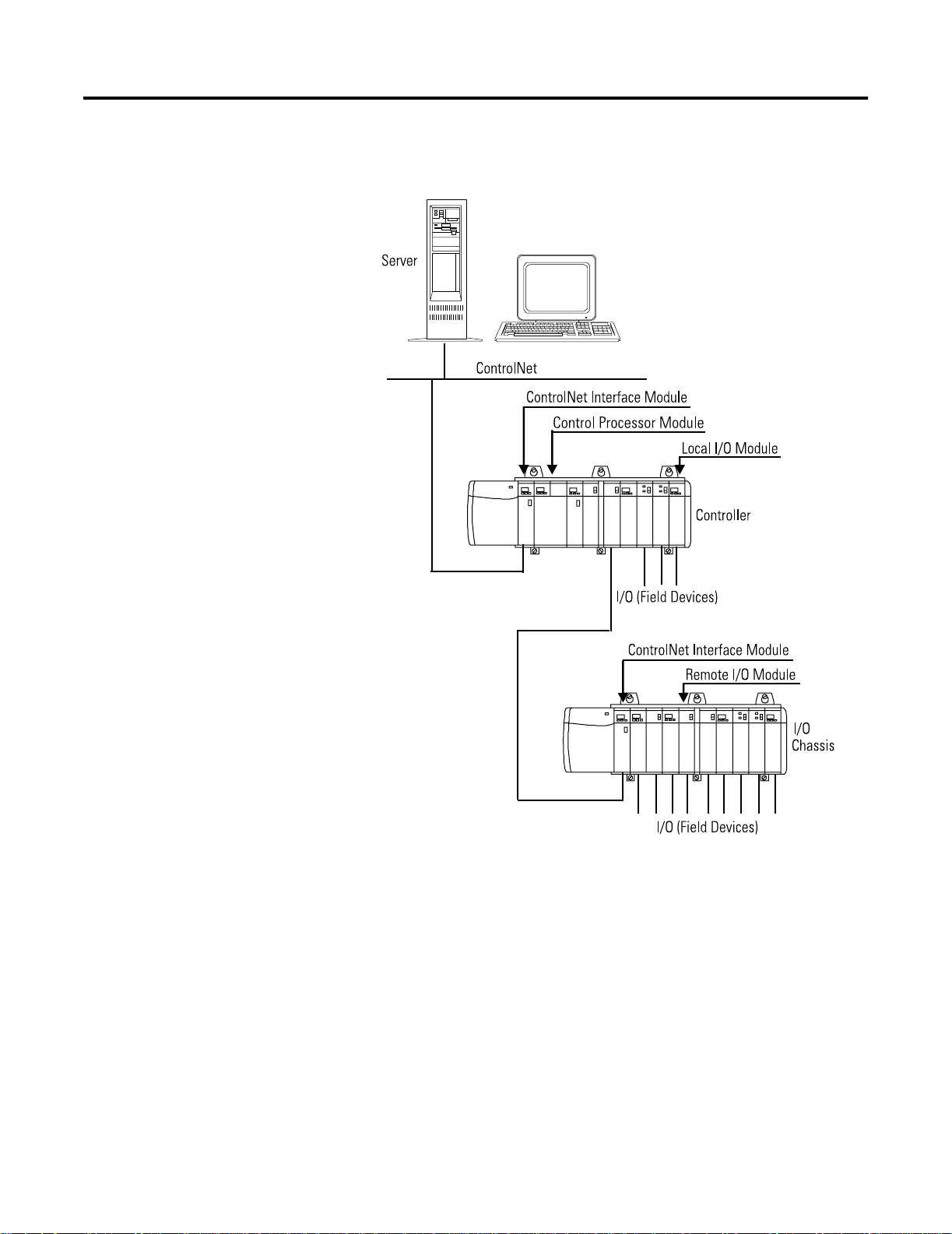
Figure 1.1 on page 1-2 shows the physical equipment that relates to
the corresponding hardware relations covered in this document for a
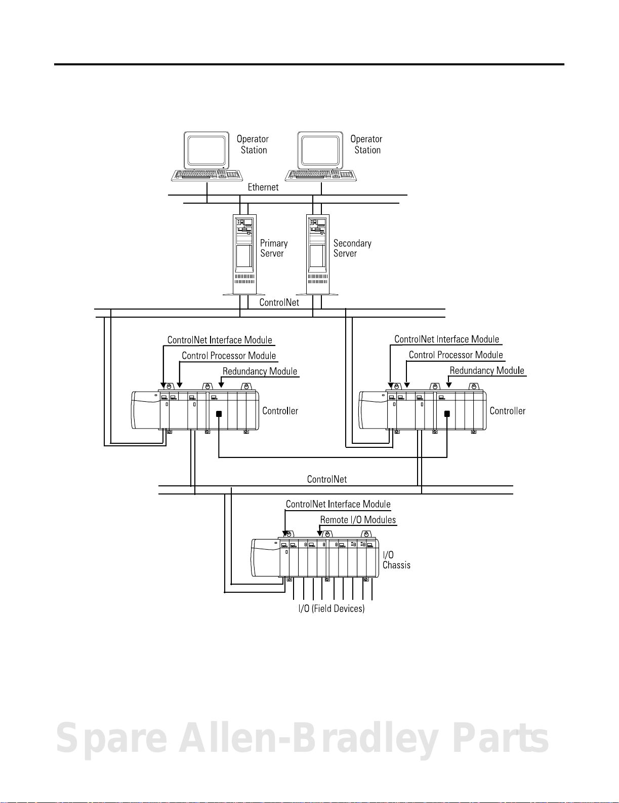
typical non-redundant system. Figure 1.2 on page 1-3 shows the
physical equipment that relates to the corresponding hardware
relations for a typical redundant system.
Spare Allen-Bradley Parts
1 Publication 1757-RM810A-EN-P - May 2002
Page 10
1-2 Introduction to Control Builder Components
Figure 1.1 Physical Equipment reference for corresponding hardware component
in typical non-redundant system architecture.
Publication 1757-RM810A-EN-P - May 2002
42778
Page 11
Introduction to Control Builder Components 1-3
Figure 1.2 Physical Equipment reference for corresponding hardware component
in typical redundant system architecture.
42779
Spare Allen-Bradley Parts
Publication 1757-RM810A-EN-P - May 2002
Page 12

1-4 Introduction to Control Builder Components
Physical equipment block types
Table identifies the physical equipment block types provided to
represent corresponding major control hardware components. The
Control Execution Environment (CEE) block is included as one of
these block types because of its relationship with the Control
Processor, although it is a functional type more than a physical one.
Physical Equipment Blocks
Type Description
Control Processor Module (CPM) Defines name/location and Control Execution
Environment (CEE) assignment for Primary and
Secondary CPMs in connected Hybrid Controllers.
This CPM is redundancy compliant.
Control Execution Environment (CEE) Supports block execution and communications in
given CPM.
Redundancy Module (RM) Defines name/location of Primary and Secondary
Redundancy Modules in Redundant Chassis Pair.
This module is redundancy compliant.
I/O Modules (IOM) Provides links for I/O channels to interface
physical I/O module to given Control Processor
Module. This includes 1756, 1757, 1797 FLEX Ex
and 1794 FLEX I/O modules.
Serial Interface Module (SIM) Provides configuration and communication
software to enable devices to communicateVia
an ASCII serial protocol to perform bi-directional
data exchange directly with the ProcessLogix
Control Processor.
Pulse Input Module Serves as the interface board between the
ProcessLogix Controller and field transducers
such as tachometers, flow meters, and magnetic
pickups. Module block descriptions are listed
under Functional Blocks, on page 3-73.
Publication 1757-RM810A-EN-P - May 2002
Page 13
Introduction to Control Builder Components 1-5
Functional relation category
Control Builder includes comprehensive libraries of function blocks
that streamline the control strategy configuration process. You simply
“drag and drop” selected blocks into a Control Module and/or
Sequential Control Module container to emulate the necessary
functional requirements of your process.
See the Control Builder Reference Manual, publication 1757-RM808,
for more information.
The functional relation category conveniently groups function blocks
according to a related functional block type or component library. The
component libraries provide a convenient way to group related
function blocks for easy access and reference.
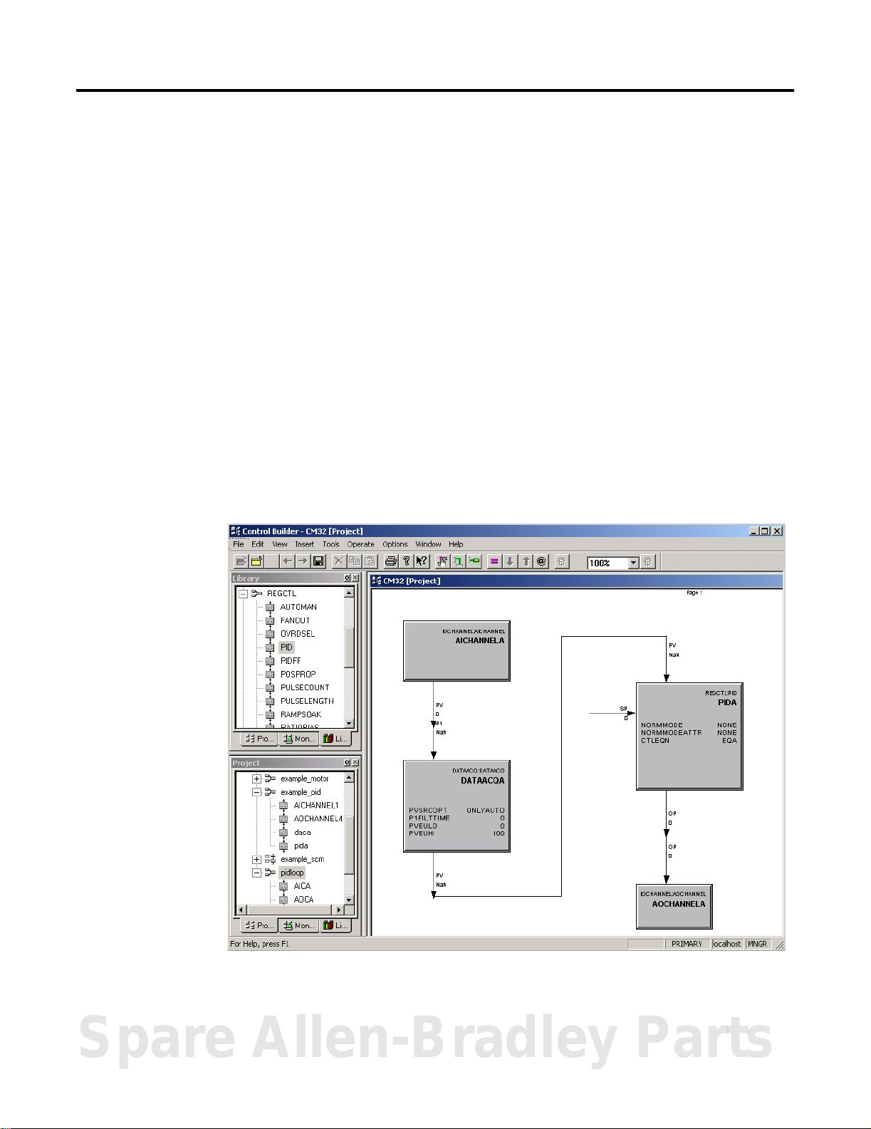
Figure 1.3 on page 1-5 shows the general graphic orientation and
Windows look-and-feel of Control Builder.
Figure 1.3 TypicalView of control module configuration in Control Builder.
Spare Allen-Bradley Parts
Publication 1757-RM810A-EN-P - May 2002
Page 14

1-6 Introduction to Control Builder Components
Functional block types
Table identifies the functional block types used to represent a group
of corresponding function blocks provided in Control Builder. These
block types are used as a way to simplify information retrieval for a
given function block, and do not necessarily correspond to an actual
Control Builder function.
Functional Blocks
Type Description
System/
Continuous Control/
Sequential Control
Auxiliary Includes block types for performing auxiliary control functions, such as: calculation, general
Device Control Provides a multi-input/multi-output function that provides an interface to discrete devices such as
Data Acquisition Provides signal conditioning for a process inputValue from another function block.
I/O Channel (IOC) Includes channel block types (analog input, analog output, digital input, digital output, pulse width
Logic Provides a set of Boolean, selection and comparison functions to be used as a basis for integrated
Regulatory Control Includes block types for building internal control loops.
Sequential Control Module Includes block types for building a sequential control function.
Utility Includes block types for performing utility control functions, such as: status flag, numeric storage
ControlNet Interoperability
(Exchange) Blocks
Control Module (CM) is a Control Builder “container” that uses predefined continuous (discrete)
control function blocks to define a given process control strategy.
Sequential Control Module (SCM) is a Control Builder “container” that uses predefined sequential
control function blocks to define the sequential operation for a given process control strategy.
linearization and totalization.
motors, pumps, solenoidValves, and motor-operatedValves.
modulator) to represent I/O points that are device independent; each I/O channel type has a
standard interface with control function blocks.
This category also includes array channel blocks to support communications with the associated
Serial Interface Module and the connected Field Terminal Assembly (FTA) device. You assign an
array channel block to one of the SIM block’s 32 channels as well as designating which of the two
FTAs it is associated with. The array channel block types are flag, numeric, and text.
logic control.
and timer capabilities. Blocks have been added for message, data array, and parameter type
convert support.
Includes block types for performing ControlNet Interoperability functions, such as: Flag, Numeric
and Text storage.
Pulse Input Channel/ Module Blocks Provides a standard interface to the Pulse Input Module, 1757-PIM.
PROFIBUS Interface Provides a standard interface to the PROFIBUS Interface Module, SST-PFBCLX.
Fieldbus Interface Provides a standard interface to the Fieldbus Interface Module, 1757-FIM.
Publication 1757-RM810A-EN-P - May 2002
Page 15

Introduction to Control Builder Components 1-7
Component Libraries
System (SYSTEM) Library
The System Library includes the function blocks listed below. Detailed
descriptions are given in the following chapter titled Functional
Blocks.
• CONTROL MODULE
• SEQUENTIAL CONTROL MODULE
Auxiliary (AUXILIARY) Library
The Auxiliary Library includes the function blocks listed below.
Detailed descriptions are given in the following chapter titled
Functional Blocks.
• AUXCALC
• DEADTIME
• GENLIN
• LEADLAG
• TOTALIZER
Device Control (DEVCTL) Library
The Device Control Library includes the DEVCTL function block. A
detailed description is given in the following chapter titled Functional
Blocks.
Data Acquisition (DATAACQ) Library
The Data Acquisition Library includes the DATAACQ function block. A
detailed description is given in the following chapter titled Functional
Blocks.
Spare Allen-Bradley Parts
Publication 1757-RM810A-EN-P - May 2002
Page 16

1-8 Introduction to Control Builder Components
I/O Module Library
Input/Output Module (IO) Library
The Input/Output Module Library includes the Input/Output Module
(IOM) function blocks listed in the following table. Blocks are
identified by model number. Detailed descriptions are presented in
the following chapter titled Functional Blocks.
IOM Function
Blocks
1756-IA8D 8 Diagnostic Input 120V ac Yes
1756-IA16 16 Digital Input 120V ac No
1756-IA16I 16 Digital Input 120V ac Yes
1756-IB32 32 Digital Input 24V dc No
1756-IB16D 16 Diagnostic Input 24V dc Yes
1756-IB16I 16 Digital Input 24V dc Yes
1756-IF6I 6 Analog Input 10V and
1756-IF16 16 Analog Input 10V and
1756-IM16I 16 Digital Input 220V ac Yes
1756-IT6I 6 Resistance Temperature Detector (RTD) Input Resistance Yes
1756-IR6I 6 Thermocouple Input Low level mV No
1756-OA8D 8 Diagnostic Output 120V ac Yes
1756-OA16 16 Digital Output 120/220V ac No
1756-OA16I 16 Digital Output 120/220V ac Yes
Number of Channels Type Rating Isolated
Yes
4 to 20 mA
No
4 to 20 mA
1756-OB16D 16 Diagnostic Output 24V dc Yes
1756-OB32 32 Digital Output 24V dc No
1756-OB16I 16 Digital Output 24V dc Yes
1756-OF6CI 6 Analog Output 4 to 20 mA Yes
TC-OAV061 6 Analog Output 10V Yes
1756-OF8 8 Analog Output 10V and
4 to 20 mA
TC-MUX021 Up to 32 FTA Array
Points
Publication 1757-RM810A-EN-P - May 2002
Bi-directional data exchange with devices
using ASCII serial protocol communications
Modbus FTA or
A-B FTA
No
Page 17

Introduction to Control Builder Components 1-9
Input/Output Channel (IOCHANNEL) Library
The Input/Output Channel Library includes the function blocks listed
below. Detailed descriptions are given in the following chapter titled
Functional Blocks.
• AICHANNEL
• DOCHANNEL
• AOCHANNEL
• PWMCHANNEL
• DICHANNEL
• SIFLAGARRCH
• SINUMARRCH
• SITEXTARRCH
Logic (LOGIC) Library
The Logic Library includes the function blocks listed below. Detailed
descriptions are given in the following chapter titled Functional
Blocks.
• AND
• CHECKBAD
• DELAY
• EQ
• FTRIG
• GE
• GT
• LE
• LIMIT
• LT
• MAX
• MAXPULSE
• MIN
• MINPULSE
• MUX
• MUXREAL
• MVOTE
• NAND
• NE
• nOON
• NOR
• NOT
• OFFDELAY
• ONDELAY
• OR
• PULSE
• QOR
• ROL
• ROR
• RS
• RTRIG
• SEL
• SELREAL
• SHL
• SHR
• SR
• TRIG
• WATCHDOG
• XOR
• 2OO3
Spare Allen-Bradley Parts
Publication 1757-RM810A-EN-P - May 2002
Page 18

1-10 Introduction to Control Builder Components
Regulatory Control (REGCTL) library
The Regulatory Control Library includes the function blocks listed
below. Detailed descriptions are given in the following chapter titled
Functional Blocks.
• AUTOMAN
• FANOUT
• OVRDSEL
• PID
• PIDEXTRESET
• PIDFF
• POSPROP
• PULSECOUNT
• PULSELENGTH
• RAMPSOAK
• RATIOBIAS
• REGCALC
• REMCAS
• SWITCH
Sequential Control Module (SCM) library
The Sequential Control Module Library includes the function blocks
listed below. Detailed descriptions are given in the following chapter
titled Functional Blocks.
• HANDLER
• STEP
• TRANSITION
Publication 1757-RM810A-EN-P - May 2002
Utility (UTILITY) Library
The Utility Library includes the function blocks listed below. Detailed
descriptions are given in the following chapter titled Functional
Blocks.
• FLAG
• FLAGARRAY
• MESSAGE
• NUMERIC
• NUMERICARRAY
• PUSH
• TEXTARRAY
• TIMER
• TYPECONVERT
Page 19

Introduction to Control Builder Components 1-11
ControlNet Interoperability (Exchange) Library
The Exchange Library includes the function blocks listed below.
Detailed descriptions are given in the following chapter titled
Functional Blocks.
• REQFLAGARRAY
• RSPFLAGARRAY
• REQNUMARRAY
• RSPNUMARRAY
• REQTEXTARRAY
• RSPTEXTARRAY
Pulse Input Channel/Module (PULSEINPUT) Library
The Pulse Input Channel/Module Library includes the function blocks
listed below. Detailed descriptions are given in the following chapter
titled Functional Blocks.
• Pulse Input Channel with Fast Cutoff
• Pulse Input Channel
• Pulse Input Module
• Pulse Input Totalizer
1797 FLEX Ex Modules (RAIL_IO_HAZ)
The 1797 FLEX Ex I/O Library includes the IOM blocks associated
with the 1797 FLEX EX components designed for use in locations with
potentially explosive atmospheres. Please refer to the 1797 FLEX Ex
Implementation Guide in Knowledge Builder for complete details
about the 1797 FLEX Ex I/O Modules.
Profibus Interface (PBUSIF) Library
The Profibus Interface Library includes the blocks associated with
linking Profibus devices with the ProcessLogix system. Please refer to
the Profibus Interface Implementation Guide in Knowledge Builder
for complete details about Profibus components.
Spare Allen-Bradley Parts
Publication 1757-RM810A-EN-P - May 2002
Page 20

1-12 Introduction to Control Builder Components
1794 FLEX I/O Modules (RAIL_IO)
The 1794 FLEX I/O Module library includes the IOM blocks associated
with the 1794 FLEX I/O components designed for use in general
purpose locations. Please refer to the 1794 FLEX I/O Implementation
Guide in Knowledge Builder for complete details about the 1794 FLEX
I/O Modules.
Fieldbus Interface (FBUSIF) Library
The Fieldbus Interface Library includes the IOM and IOC blocks
associated with linking F
ProcessLogix system through the Linking Device. Please refer to the
Linking Device Implementation Guide in Knowledge Builder for
complete details about the Fieldbus Interface components.
OUNDATION Fieldbus devices with the
Publication 1757-RM810A-EN-P - May 2002
Page 21

Physical Equipment Blocks
Chapter
2
Overview
This section provides detailed reference data for each physical
equipment block type that is part of the hardware relation category for
Control Builder.
See the ProcessLogix Function Block Parameter Reference Manual,
publication 1757-RM811A-EN-P, for definitions of each parameter.
Control Processor Module (CPM)
Description Identifies the primary and secondary Control Processor Modules (CPM) and associated CEE to implement the control
strategy built in the Control Builder application. This block’s parameters characterize the redundant CPM as a whole.
This block always runs at an execution period of 2 seconds. It is redundancy compliant.
Function • Supports Hybrid Controller Redundant Chassis Pair hardware configurations.
• Publishes parameters describing the status and configuration of the CPM.
• Processes the computation of statistical parameters and notification reporting.
• Serves as a faceplate for any parameters whose scope corresponds to that of the entire CPM.
• Secondary waits to take control if the “Primary” fails.
• The address of the Secondary chassis equals the address of the Primary chassis plus one.
Inputs Integrated Control Protocol (ICP) communications
Outputs See above.
Parameters ALMENBSTATE
BATTERYNOTOK
CCLCNT
CCLINFO
CCLLOADSTAT
CCLNAME
CEECOMMAND
CEESTATE
CPMCOMMAND
[0..numChans-1]
CPMSTATE
CPUFREEAVG
CPUFREEMIN
DESC
DRIVERNAME
EUDESC
FREEMEM
FREEMEMINK
HIALM
INALM
IPADDRESS
MAXFREEBLKSZ
MAXFREEINK
MODISREDUN
MULREDUNSTAT
NETWORKTYPE
PCMSTATE
RAMSCRUBERRS
RAMSWEEPERR
RDNCAPABILITY
RDNCHASSISID
RDNDELAYAVG
RDNDELAYMAX
RDNSYNCSTATE
RDNXFERAVG
RDNXFERMAX
SCANAREA
SCANASSOCDSP
SCANCTRLLVL
SCANEUHI
SCANEULO
SCANGRPDTL
SCANPNTDTL
SECMODNAME
SECNAMESTRING
SECTMPNAME
SLOTNUMBER
STATSRESET
TOTALMEM
TOTALMEMINK
ULCNBMAC
USEDMEM
USEDMEMINK
USESIM
Spare Allen-Bradley Parts
1 Publication 1757-RM810A-EN-P - May 2002
Page 22

2-2 Physical Equipment Blocks
Control Execution Environment (CEE)
Description Provides control functionality for associated Control Processor Module block. This block’s parameters characterize the
CEE within the CPM. In the future, multiple CEEs may be assigned to a single CPM.
This block always runs at an execution period of 2 seconds.
There are two versions of the CEE available, the standard version CEE-50ms, and the fast version CEE-5ms.
Function • Publishes parameters describing the status and configuration of the CEE.
• Processes the computation of statistical parameters and notification reporting.
• Runs on the CPM hardware platform. In the future, CEE will run on other platforms as well.
• Serves as a faceplate for any parameters whose scope corresponds to that of the CEE rather than the CPM as a
whole.
• Supports configurable subscription rate for peer-to-peer communications.
• Supports peer-to-peer communications among CEEs assigned to CPMs located in the same management domain.
• Sequential Control Module function blocks are supported. Special care should be taken in configuring the SCMs in
5 msec CEE.
Inputs Integrated Control Protocol (ICP) communications
Outputs See above.
Parameters ALMENBSTATE
BASEPERIOD
CEECOMMAND
CEESTATE
CPUCYCLEAVG [0..39]
CPUCYCLEMAX [0..39]
CPUFREEAVG
CRCYCLEOVRN [0..40]
DESC
EUDESC
HIALM
INALM
LSCYCLEOVRN [0..40]
NUMACCRQUAVG
NUMACCRQUMAXNUMCC
LRQU
NUMNTFRQUAVG
NUMNTFRQUMAX
NUMPARRSPAVG
NUMPARRSPMAX
SCANAREA
SCANASSOCDSP
SCANCTRLLVL
SCANEUHI
SCANEULO
SCANGRPDTL
SCANPNTDTL
STATSRESET
SUBSCPERIOD
Publication 1757-RM810A-EN-P - May 2002
Page 23

Physical Equipment Blocks 2-3
Redundancy Module (RM)
Description Identifies the Primary and Secondary Redundancy Modules connected by a dedicated redundancy cable in a
Redundant Chassis Pair (RCP). It associates the Primary RM with its “partner” Secondary RM block.
This block always runs at an execution period of 2 seconds. It is redundancy compliant.
Function • Provides parameters describing the status and configuration of the RM.
• Handles notification reporting.
• Serves as a faceplate for any parameters whose scope corresponds to that of the RM as a whole.
Inputs Integrated Control Protocol (ICP) communications
Redundancy communications through the redundancy cable.
Outputs See above.
Parameters ALMENBSTATE
AREVISION
AUTOSYNCCMD
AUTOSYNCOPT
AUTOSYNCSTAT
AVERSION
BECMPRICMD
BREVISION
BVERSION
CHANINUSE [0..31]
CJDISABLE
CLKADJUST
CLKTIME
CLKZONE
CONFIGURED
DISPPOS
DISQSECCMD
DRIVERNAME
ENTERSBYCMD
ERRFL
ERRORCODE
ERRORMSGIDX
EUDESC
GENSTATE
GENSTATEA
HIALM
INTISWCMD
IPADDRESS
KEYWORD
LASTSYNCABRT
LASTSYNCARES
MAJRECFAULT
MAJURECFAULT
MINRECFAULT
MINURECFAULT
MODCOMPATA
MODTYPEA
MULREDUNSTAT
NETWORKTYPE
NUMSLOTS
PREVISION
PRODCODE
PRODTYPE
PRODTYPEA
PROGCMD
PROGCMDRECOG
QUALPROGA
READINESS
READINESSA
RECOVMSGIDX
REDUNSTATE
REDUNSTATEA
REFRESHMS
SCANAREA
SCANASSOCDSP
SCANCTRLLVL
SCANEUHI
SCANEULO
SCANGRPDTL
SCANPNTDTL
SECMODNAME
SECNAMESTRING
SECTMPNAME
SERIALNUM
SLOTNUMBER
STDTIME
SWAPCTRLCMD
SWAPPOSCMD
SWAPSBYCMD
SYNCSECCMD
ULCNBMAC
VENDORID
WCTCLKTIME
Spare Allen-Bradley Parts
Publication 1757-RM810A-EN-P - May 2002
Page 24

2-4 Physical Equipment Blocks
Input Module Blocks
1756-IA16
1756-IA16 (16-Channel - 120Vac Non-Isolated - Digital Input)
Description Identifies the physical IOM for the CPM to provide links to associated IOC.
Function • Defines type of IOM, number of channels, execution state, and communications path for data.
• Provides link to IOC through IO manager software resident in the CPM.
• Executes once every cycle.
• Includes IOC assignment to one of 16 channels (points), as part of IOM configuration.
Inputs Real-time data transmission from physical device.
Outputs Real-time data transmission to configured IOC.
Parameters ALMENBSTATE
ASACONNSTS
ASAERRCODE
ASAERRINFO
CATNUMBER
CEESTATE
CHANTEXT
COS [0..numChans-1]
DESC
DLCNBSLOT
ELOF [0..numChans-1]
ESTWEIGHT
EUDESC
EWIREOFF [0..numChans-1]
EXECSTATE
FILTERHDR
[0..numChans-1]
FILTEROFF [0..numChans/8]
FILTERON [0..numChans/8]
HIALM
HWFAULT [0..numChans-1]
INALM
IOMSLOT
IOMTYPE
KEYWORD
MAJORREV
MINORREV
NOFIELDPWR
[0..numChans-1]
NUMCHANS
NUMCONN
NUMDISCONN
NUMSHUTDOWN
ORDERINCEE
ORDERINCM
PERIOD
PHASE
PRODTYPE
PVVAL [0..numChans-1]
SCANAREA
SCANASSOCDSP
SCANCTRLLVL
SCANEUHI
SCANEULO
SCANGRPDTL
SCANPNTDTL
ULCNBMAC
UPDATOPT
VENDOR
WIREOFF [0..numChans-1]
Publication 1757-RM810A-EN-P - May 2002
Page 25

Physical Equipment Blocks 2-5
1756-IA16I
16-Channel - 120Vac Isolated - Digital Input
Description Identifies the physical IOM for the CPM to provide links to associated IOC.
Function • Defines type of IOM, number of channels, execution state, and communications path for data.
• Provides link to IOC through IO manager software resident in the CPM.
• Executes once every cycle.
• Includes IOC assignment to one of 16 channels (points), as part of IOM configuration.
Inputs Real-time data transmission from physical device.
Outputs Real-time data transmission to configured IOC.
Parameters ALMENBSTATE
ASACONNSTS
ASAERRCODE
ASAERRINFO
CATNUMBER
CEESTATE
CHANTEXT
COS [0..numChans-1]
DESC
DLCNBSLOT
ELOF [0..numChans-1]
ESTWEIGHT
EUDESC
EWIREOFF [0..numChans-1]
EXECSTATE
FILTERHDR
[0..numChans-1]
FILTEROFF [0..numChans/8]
FILTERON [0..numChans/8]
HIALM
HWFAULT [0..numChans-1]
INALM
IOMSLOT
IOMTYPE
KEYWORD
MAJORREV
MINORREV
NOFIELDPWR
[0..numChans-1]
NUMCHANS
NUMCONN
NUMDISCONN
NUMSHUTDOWN
ORDERINCEE
ORDERINCM
PERIOD
PHASE
PRODTYPE
PVVA L [0..numChans-1]
SCANAREA
SCANASSOCDSP
SCANCTRLLVL
SCANEUHI
SCANEULO
SCANGRPDTL
SCANPNTDTL
ULCNBMAC
UPDATOPT
VENDOR
WIREOFF [0..numChans-1]
Spare Allen-Bradley Parts
Publication 1757-RM810A-EN-P - May 2002
Page 26

2-6 Physical Equipment Blocks
1756-IA8D
8-Channel - 120Vac Diagnostic Input
Description Identifies the physical IOM for the CPM to provide links to associated IOC and provides selected diagnostic
information for associated channels.
Function • Defines type of IOM, number of channels, execution state, and communications path for data.
• Supports the following diagnostics, which are user configurable for each channel:
– Open Wire Detection: Senses when current input for a given channel falls below a certain value. When an
input uses dry contacts, you must include a bleed resistor in the input. You may not need a bleed resistor for
solid state contacts.
– Loss of Field Power: Senses when field power of a group of channels is lost.
• Provides link to IOC through IO manager software resident in the CPM.
• Executes once every cycle.
• Includes IOC assignment to one of 8 channels (points), as part of IOM configuration.
Inputs Real-time data transmission from physical device.
Outputs Real-time data transmission to configured IOC.
Parameters ALMENBSTATE
ASACONNSTS
ASAERRCODE
ASAERRINFO
CATNUMBER
CEESTATE
CHANTEXT
DESC
DLCNBSLOT
ESTWEIGHT
EUDESC
EXECSTATE
HIALM
INALM
IOMSLOT
IOMTYPE
KEYWORD
MAJORREV
MINORREV
NUMCHANS
NUMCONN
NUMDISCONN
NUMSHUTDOWN
ORDERINCEE
ORDERINCM
PERIOD
PHASE
PRODTYPE
SCANAREA
SCANASSOCDSP
SCANCTRLLVL
SCANEUHI
SCANEULO
SCANGRPDTL
SCANPNTDTL
ULCNBMAC
UPDATOPT
VENDOR
Publication 1757-RM810A-EN-P - May 2002
Page 27

Physical Equipment Blocks 2-7
1756-IB16D
116-Channel - 24Vdc Diagnostic Input
Description Identifies the physical IOM for the CPM to provide links to associated IOC and provides selected diagnostic
information for associated channels.
Function • Defines type of IOM, number of channels, execution state, and communications path for data.
• Supports the following diagnostic, which is user configurable for each channel:
– Open Wire Detection: Senses when current input for a given channel falls below a certain value. When an
input uses dry contacts, you must include a bleed resistor in the input. You may not need a bleed resistor for
solid state contacts.
• Provides link to IOC through IO manager software resident in the CPM.
• Executes once every cycle.
• Includes IOC assignment to one of 16 channels (points), as part of IOM configuration.
Inputs Real-time data transmission from physical device.
Outputs Real-time data transmission to configured IOC.
Parameters ALMENBSTATE
ASACONNSTS
ASAERRCODE
ASAERRINFO
CATNUMBER
CEESTATE
CHANTEXT
DESC
DLCNBSLOT
ESTWEIGHT
EUDESC
EXECSTATE
HIALM
INALM
IOMSLOT
IOMTYPE
KEYWORD
MAJORREV
MINORREV
NUMCHANS
NUMCONN
NUMDISCONN
NUMSHUTDOWN
ORDERINCEE
ORDERINCM
PERIOD
PHASE
PRODTYPE
SCANAREA
SCANASSOCDSP
SCANCTRLLVL
SCANEUHI
SCANEULO
SCANGRPDTL
SCANPNTDTL
ULCNBMAC
UPDATOPT
VENDOR
Spare Allen-Bradley Parts
Publication 1757-RM810A-EN-P - May 2002
Page 28

2-8 Physical Equipment Blocks
1756-IB16I
116 Channel - 24Vdc Isolated - Digital Input
Description Identifies the physical IOM for the CPM to provide links to associated IOC.
Function • Defines type of IOM, number of channels, execution state, and communications path for data.
• Provides link to IOC through IO manager software resident in the CPM.
• Executes once every cycle.
• Includes IOC assignment to one of 16 channels (points), as part of IOM configuration.
Inputs Real-time data transmission from physical device. Data is “triggered”, or is current digital (Boolean) value.)
Outputs Real-time data transmission to configured IOC.
Parameters ALMENBSTATE
ASACONNSTS
ASAERRCODE
ASAERRINFO
CATNUMBER
CEESTATE
CHANTEXT
COS [0..numChans-1]
DESC
DLCNBSLOT
ELOF [0..numChans-1]
ESTWEIGHT
EUDESC
EWIREOFF
[0..numChans-1]
EXECSTATE
FILTERHDR
[0..numChans-1]
FILTEROFF
[0..numChans/8]
FILTERON [0..numChans/8]
HIALM
HWFAULT [0..numChans-1]
INALM
IOMSLOT
IOMTYPE
KEYWORD
MAJORREV
MINORREV
NOFIELDPWR
[0..numChans-1]
NUMCHANS
NUMCONN
NUMDISCONN
NUMSHUTDOWN
ORDERINCEE
ORDERINCM
PERIOD
PHASE
PRODTYPE
PVVAL [0..numChans-1]
SCANAREA
SCANASSOCDSP
SCANCTRLLVL
SCANEUHI
SCANEULO
SCANGRPDTL
SCANPNTDTL
ULCNBMAC
UPDATOPT
VENDOR
WIREOFF [0..numChans-1]
1756-IB32
32 Channel - 24Vdc Non-Isolated - Digital Input
Description Identifies the physical IOM for the CPM to provide links to associated IOC.
Function • Defines type of IOM, number of channels, execution state, and communications path for data.
• Provides link to IOC through IO manager software resident in the CPM.
• Executes once every cycle.
• Includes IOC assignment to one of 32 channels (points), as part of IOM configuration.
Inputs Real-time data transmission from physical device. Data is “triggered”, or is current digital (Boolean) value.)
Outputs Real-time data transmission to configured IOC.
Parameters ALMENBSTATE
ASACONNSTS
ASAERRCODE
ASAERRINFO
CATNUMBER
CEESTATE
CHANTEXT
COS [0..numChans-1]
DESC
DLCNBSLOT
ELOF [0..numChans-1]
ESTWEIGHT
EUDESC
Publication 1757-RM810A-EN-P - May 2002
EWIREOFF
[0..numChans-1]
EXECSTATE
FILTERHDR
[0..numChans-1]
FILTEROFF
[0..numChans/8]
FILTERON [0..numChans/8]
HIALM
HWFAULT [0..numChans-1]
INALM
IOMSLOT
IOMTYPE
KEYWORD
MAJORREV
MINORREV
NOFIELDPWR
[0..numChans-1]
NUMCHANS
NUMCONN
NUMDISCONN
NUMSHUTDOWN
ORDERINCEE
ORDERINCM
PERIOD
PHASE
PRODTYPE
PVVAL [0..numChans-1]
SCANAREA
SCANASSOCDSP
SCANCTRLLVL
SCANEUHI
SCANEULO
SCANGRPDTL
SCANPNTDTL
ULCNBMAC
UPDATOPT
VENDOR
WIREOFF [0..numChans-1]
Page 29

Physical Equipment Blocks 2-9
1756-IF6I
6-Channel, 10V, 4–20mA, Isolated Analog Input
Description Identifies the physical IOM for the CPM to provide links to associated IOC.
Function • Defines type of IOM, number of channels, execution state, and communications path for data.
• Provides link to IOC through IO manager software resident in the CPM.
• Executes once every cycle.
• Includes IOC assignment to one of 6 channels (points), as part of IOM configuration.
Inputs Real-time data transmission from physical device.
Outputs Real-time data transmission to configured IOC.
Parameters ALMENBSTATE
ASACONNSTS
ASAERRCODE
ASAERRINFO
BADCAL [0..numChans-1]
CALBIAS [0..numChans-1]
CATNUMBER
CEESTATE
CHANTEXT
CJDISABLE
CJOFFSET
CJOFFSET
[0..numChans-1]
DESC
DIGFILTER
[0..numChans-1]
DLCNBSLOT
ESTWEIGHT
EUDESC
EXECSTATE
HIALM
HIGHENG [0..numChans-1]
HIGHSIGNAL
[0..numChans-1]
IFTRANS
INALM
INPUTRANGE
[0..numChans-1]
IOMSLOT
IOMTYPE
KEYWORD
LOWENG [0..numChans-1]
LOWSIGNAL
[0..numChans-1]
MAJORREV
MINORREV
NOTCHFILTER
[0..numChans-1]
NUMCHANS
NUMCONN
NUMDISCONN
NUMSHUTDOWN
OHMOFFSET
[0..numChans-1]
ORDERINCEE
ORDERINCM
OVERRANGE
[0..numChans-1]
PERIOD
PHASE
PRODTYPE
PVRAW [0..numChans-1]
RTPPRESENT
SAMPLERATE
1756-IF16
16-Channel,10V, 4 –20mA, Non-Isolated Analog Input
Description Identifies the physical IOM for the CPM to provide links to associated IOC.
SCANAREA
SCANASSOCDSP
SCANCTRLLVL
SCANEUHI
SCANEULO
SCANGRPDTL
SCANPNTDTL
SENSORTYPE
[0..numChans-1]
SIPTYPE [0..numChans-1]
TEMPMODE
ULCNBMAC
UNDERRANGE
[0..numChans-1]
UPDATOPT
VENDOR
Function • Defines type of IOM, number of channels, execution state, and communications path for data.
• Provides link to IOC through IO manager software resident in the CPM.
• Executes once every cycle.
• Includes IOC assignment to one of 16 channels (points), as part of IOM configuration.
Inputs Real-time data transmission from physical device.
Outputs Real-time data transmission to configured IOC.
Parameters ALMENBSTATE
ASACONNSTS
ASAERRCODE
ASAERRINFO
CATNUMBER
CEESTATE
CHANTEXT
DESC
DLCNBSLOT
ESTWEIGHT
EUDESC
EXECSTATE
HIALM
INALM
IOMSLOT
IOMTYPE
KEYWORD
MAJORREV
MINORREV
NUMCHANS
NUMCONN
NUMDISCONN
NUMSHUTDOWN
ORDERINCEE
ORDERINCM
PERIOD
PHASE
PRODTYPE
SCANAREA
SCANASSOCDSP
SCANCTRLLVL
SCANEUHI
SCANEULO
SCANGRPDTL
SCANPNTDTL
ULCNBMAC
UPDATOPT
VENDOR
Spare Allen-Bradley Parts
Publication 1757-RM810A-EN-P - May 2002
Page 30

2-10 Physical Equipment Blocks
1756-IM16I
6-Channel - 220Vac Isolated - Digital Input
Description Identifies the physical IOM for the CPM to provide links to associated IOC.
Function • Defines type of IOM, number of channels, execution state, and communications path for data.
• Provides link to IOC through IO manager software resident in the CPM.
• Executes once every cycle.
• Includes IOC assignment to one of 16 channels (points), as part of IOM configuration.
Inputs Real-time data transmission from physical device.
Outputs Real-time data transmission to configured IOC.
Parameters ALMENBSTATE
ASACONNSTS
ASAERRCODE
ASAERRINFO
CATNUMBER
CEESTATE
CHANTEXT
COS [0..numChans-1]
DESC
DLCNBSLOT
ELOF [0..numChans-1]
ESTWEIGHT
EUDESC
EWIREOFF [0..numChans-1]
EXECSTATE
FILTERHDR
[0..numChans-1]
FILTEROFF [0..numChans/8]
FILTERON [0..numChans/8]
HIALM
HWFAULT [0..numChans-1]
INALM
IOMSLOT
IOMTYPE
KEYWORD
MAJORREV
MINORREV
NOFIELDPWR
[0..numChans-1]
NUMCHANS
NUMCONN
NUMDISCONN
NUMSHUTDOWN
ORDERINCEE
ORDERINCM
PERIOD
PHASE
PRODTYPE
PVVAL [0..numChans-1]
SCANAREA
SCANASSOCDSP
SCANCTRLLVL
SCANEUHI
SCANEULO
SCANGRPDTL
SCANPNTDTL
ULCNBMAC
UPDATOPT
VENDOR
WIREOFF [0..numChans-1]
1756-IR6I
6-Channel - RTD Input
Description Identifies the physical IOM for the CPM to provide links to associated IOC.
Function • Defines type of IOM, number of channels, execution state, and communications path for data.
• Provides link to IOC through IO manager software resident in the CPM.
• Executes once every cycle.
• Includes IOC assignment to one of 6 channels (points), as part of IOM configuration.
Inputs Real-time data transmission from physical device.
Outputs Real-time data transmission to configured IOC.
Parameters ALMENBSTATE
ASACONNSTS
ASAERRCODE
ASAERRINFO
CATNUMBER
CEESTATE
CHANTEXT
DESC
DLCNBSLOT
ESTWEIGHT
Publication 1757-RM810A-EN-P - May 2002
EUDESC
EXECSTATE
HIALM
INALM
IOMSLOT
IOMTYPE
KEYWORD
MAJORREV
MINORREV
NUMCHANS
NUMCONN
NUMDISCONN
NUMSHUTDOWN
ORDERINCEE
ORDERINCM
PERIOD
PHASE
PRODTYPE
SCANAREA
SCANASSOCDSP
SCANCTRLLVL
SCANEUHI
SCANEULO
SCANGRPDTL
SCANPNTDTL
ULCNBMAC
UPDATOPT
VENDOR
Page 31

Physical Equipment Blocks 2-11
1756-IT6I
6-Channel - Thermocouple Input
Description Identifies the physical IOM for the CPM to provide links to associated IOC.
Function • Defines type of IOM, number of channels, execution state, and communications path for data.
• Provides link to IOC through IO manager software resident in the CPM.
• Executes once every cycle.
• Includes IOC assignment to one of 6 channels (points), as part of IOM configuration.
Inputs Real-time data transmission from physical device.
Outputs Real-time data transmission to configured IOC.
Parameters ALMENBSTATE
ASACONNSTS
ASAERRCODE
ASAERRINFO
CATNUMBER
CEESTATE
CHANTEXT
DESC
DLCNBSLOT
ESTWEIGHT
EUDESC
EXECSTATE
HIALM
INALM
IOMSLOT
IOMTYPE
KEYWORD
MAJORREV
MINORREV
NUMCHANS
NUMCONN
NUMDISCONN
NUMSHUTDOWN
ORDERINCEE
ORDERINCM
PERIOD
PHASE
PRODTYPE
SCANAREA
SCANASSOCDSP
SCANCTRLLVL
SCANEUHI
SCANEULO
SCANGRPDTL
SCANPNTDTL
ULCNBMAC
UPDATOPT
VENDOR
Spare Allen-Bradley Parts
Publication 1757-RM810A-EN-P - May 2002
Page 32

2-12 Physical Equipment Blocks
Output Module Blocks
1756-OA16
116-Channel - 120/220Vac Non-Isolated - Digital Output
Description Identifies the physical IOM for the CPM to provide links to associated IOC.
Function • Defines type of IOM, number of channels, execution state, and communications path for data.
• Provides link to IOC through IO manager software resident in the CPM.
• Executes once every cycle.
• Includes IOC assignment to one of 16 channels (points), as part of IOM configuration.
Inputs Real-time data transmission from configured IOC.
Outputs Real-time data transmission to physical device.
Parameters ALMENBSTATE
ASACONNSTS
ASAERRCODE
ASAERRINFO
CATNUMBER
CEESTATE
CHANTEXT
DESC
DLCNBSLOT
ENOLOAD
[0..numChans-1]
ESTWEIGHT
ETRANS
EUDESC
EVERIFY [0..numChans-1]
EXECSTATE
EZCROSS [0..numChans-1]
FAILSTATE
[0..numChans-1]
HIALM
INALM
IOMSLOT
IOMTYPE
KEYWORD
MAJORREV
MINORREV
NOFIELDPWR
[0..numChans-1]
NOLOAD [0..numChans-1]
NUMCHANS
NUMCONN
NUMDISCONN
NUMSHUTDOWN
ORDERINCEE
ORDERINCM
PERIOD
PHASE
PRODTYPE
PVSTS
PVVAL [0..numChans-1]
PWMPERIOD
[0..numChans-1]
SAFESTATE
[0..numChans-1]
SCANAREA
SCANASSOCDSP
SCANCTRLLVL
SCANEUHI
SCANEULO
SCANGRPDTL
SCANPNTDTL
SHORT [0..numChans-1]
ULCNBMAC
UPDATOPT
VENDOR
VERIFYLOST
[0..numChans-1]
Publication 1757-RM810A-EN-P - May 2002
Page 33

Physical Equipment Blocks 2-13
1756-OA16I
16-Channel - 120/220Vac Isolated - Digital Output
Description Identifies the physical IOM for the CPM to provide links to associated IOC.
Function • Defines type of IOM, number of channels, execution state, and communications path for data.
• Provides link to IOC through IO manager software resident in the CPM.
• Executes once every cycle.
• Includes IOC assignment to one of 16 channels (points), as part of IOM configuration.
Inputs Real-time data transmission from configured IOC.
Outputs Real-time data transmission to physical device.
Parameters ALMENBSTATE
ASACONNSTS
ASAERRCODE
ASAERRINFO
CATNUMBER
CEESTATE
CHANTEXT
DESC
DLCNBSLOT
ENOLOAD
[0..numChans-1]
ESTWEIGHT
ETRANS
EUDESC
EVERIFY [0..numChans-1]
EXECSTATE
EZCROSS [0..numChans-1]
FAILSTATE
[0..numChans-1]
HIALM
INALM
IOMSLOT
IOMTYPE
KEYWORD
MAJORREV
MINORREV
NOFIELDPWR
[0..numChans-1]
NOLOAD [0..numChans-1]
NUMCHANS
NUMCONN
NUMDISCONN
NUMSHUTDOWN
ORDERINCEE
ORDERINCM
PERIOD
PHASE
PRODTYPE
PVSTS
PVVAL [0..numChans-1]
PWMPERIOD
[0..numChans-1]
SAFESTATE
[0..numChans-1]
SCANAREA
SCANASSOCDSP
SCANCTRLLVL
SCANEUHI
SCANEULO
SCANGRPDTL
SCANPNTDTL
SHORT [0..numChans-1]
ULCNBMAC
UPDATOPT
VENDOR
VERIFYLOST
[0..numChans-1]
Spare Allen-Bradley Parts
Publication 1757-RM810A-EN-P - May 2002
Page 34

2-14 Physical Equipment Blocks
1756-OA8D
8-Channel - 120Vac- Diagnostic Output
Description Identifies the physical IOM for the CPM to provide links to associated IOC and provides selected diagnostic
information for associated channels.
Function • Defines type of IOM, number of channels, execution state, and communications path for data.
• Supports the following diagnostics, which are user configurable for each channel with the exception of the Short
Circuit Protection/Overload diagnostic which is always enabled:
– Short Circuit Protection/Overload: Senses when current draw for a given channel is above the limit and
protects the device from damage.
– Loss of Field Power: Senses lack of power for a channel, if zero-crossing on the ac-line power is not detected
which causes the output state to change.
– No Load/Hardware Point Fault: Senses when the output current draw falls below the threshold or a hardware
output failure occurs. It only works when the output is in the OFF state.
– Output Verification: Verifies if the actual output state matches the commanded output state for field side
verification. It only works when the output is in the ON state.
– Pulse Test: Periodically checks the output to verify that it still has the ability to change states without causing
the load to transition. (This function only operates in systems with software version R120 or greater.)
• Provides link to IOC through IO manager software resident in the CPM.
• Executes once every cycle.
• Includes IOC assignment to one of 8 channels (points), as part of IOM configuration.
Inputs Real-time data transmission from configured IOC. Data is “triggered”, or is current digital (Boolean) value or pulsed
(real) value.
Outputs Real-time data transmission to physical device.
Parameters ALMENBSTATE
ASACONNSTS
ASAERRCODE
ASAERRINFO
CATNUMBER
CEESTATE
CHANTEXT
DESC
DLCNBSLOT
ESTWEIGHT
EUDESC
EXECSTATE
HIALM
INALM
IOMSLOT
IOMTYPE
KEYWORD
MAJORREV
MINORREV
NUMCHANS
NUMCONN
NUMDISCONN
NUMSHUTDOWN
ORDERINCEE
ORDERINCM
PERIOD
PHASE
PRODTYPE
SCANAREA
SCANASSOCDSP
SCANCTRLLVL
SCANEUHI
SCANEULO
SCANGRPDTL
SCANPNTDTL
ULCNBMAC
UPDATOPT
VENDOR
Publication 1757-RM810A-EN-P - May 2002
Page 35

Physical Equipment Blocks 2-15
1756-OB16D
116-Channel - 24Vdc- Diagnostic Output
Description Identifies the physical IOM for the CPM to provide links to associated IOC and provides selected diagnostic
information for associated channels.
Function • Defines type of IOM, number of channels, execution state, and communications path for data.
• Supports the following diagnostics, which are user configurable for each channel with the exception of the Short
Circuit Protection/Overload diagnostic, which is always enabled.
– Short Circuit Protection/Overload: Senses when current draw for a given channel is above the limit and
protects the device from damage.
– No Load/Hardware Point Fault: Senses when the output current draw falls below the threshold or a hardware
output failure occurs. It only works when the output is in the OFF state.
– Output Verification: Verifies if the actual output state matches the commanded output state for field side
verification. It only works when the output is in the ON state.
– Pulse Test: Periodically checks the output to verify that it still has the ability to change states without causing
the load to transition. (This function only operates in systems with software version R120 or greater.)
• Provides link to IOC through IO manager software resident in the CPM.
• Executes once every cycle.
• Includes IOC assignment to one of 16 channels (points), as part of IOM configuration.
Inputs Real-time data transmission from configured IOC. Data is “triggered”, or is current digital (Boolean) value or pulsed
(real) value.
Outputs Real-time data transmission to physical device.
Parameters ALMENBSTATE
ASACONNSTS
ASAERRCODE
ASAERRINFO
CATNUMBER
CEESTATE
CHANTEXT
DESC
DLCNBSLOT
ESTWEIGHT
EUDESC
EXECSTATE
HIALM
INALM
IOMSLOT
IOMTYPE
KEYWORD
MAJORREV
MINORREV
NUMCHANS
NUMCONN
NUMDISCONN
NUMSHUTDOWN
ORDERINCEE
ORDERINCM
PERIOD
PHASE
PRODTYPE
SCANAREA
SCANASSOCDSP
SCANCTRLLVL
SCANEUHI
SCANEULO
SCANGRPDTL
SCANPNTDTL
ULCNBMAC
UPDATOPT
VENDOR
Spare Allen-Bradley Parts
Publication 1757-RM810A-EN-P - May 2002
Page 36

2-16 Physical Equipment Blocks
1756-OB16I
16-Channel - 24Vdc Isolated Digital Output
Description Identifies the physical IOM for the CPM to provide links to associated IOC.
Function • Defines type of IOM, number of channels, execution state, and communications path for data.
• Provides link to IOC through IO manager software resident in the CPM.
• Executes once every cycle.
• Includes IOC assignment to one of 16 channels (points), as part of IOM configuration.
Inputs Real-time data transmission from configured IOC. Data is “triggered”, or is current digital (Boolean) value or pulsed
(real) value.
Outputs Real-time data transmission to physical device.
Parameters ALMENBSTATE
ASACONNSTS
ASAERRCODE
ASAERRINFO
CATNUMBER
CEESTATE
CHANTEXT
DESC
DLCNBSLOT
ENOLOAD
[0..numChans-1]
ESTWEIGHT
ETRANS
EUDESC
EVERIFY [0..numChans-1]
EXECSTATE
EZCROSS [0..numChans-1]
FAILSTATE
[0..numChans-1]
HIALM
INALM
IOMSLOT
IOMTYPE
KEYWORD
MAJORREV
MINORREV
NOFIELDPWR
[0..numChans-1]
NOLOAD [0..numChans-1]
NUMCHANS
NUMCONN
NUMDISCONN
NUMSHUTDOWN
ORDERINCEE
ORDERINCM
PERIOD
PHASE
PRODTYPE
PVSTS
PVVAL [0..numChans-1]
PWMPERIOD
[0..numChans-1]
SAFESTATE
[0..numChans-1]
SCANAREA
SCANASSOCDSP
SCANCTRLLVL
SCANEUHI
SCANEULO
SCANGRPDTL
SCANPNTDTL
SHORT [0..numChans-1]
ULCNBMAC
UPDATOPT
VENDOR
VERIFYLOST
[0..numChans-1]
Publication 1757-RM810A-EN-P - May 2002
Page 37

Physical Equipment Blocks 2-17
1756-OB32
2-Channel - 24Vdc Non-Isolated Digital Output
Description Identifies the physical IOM for the CPM to provide links to associated IOC.
Function • Defines type of IOM, number of channels, execution state, and communications path for data.
• Provides link to IOC through IO manager software resident in the CPM.
• Executes once every cycle.
• Includes IOC assignment to one of 32 channels (points), as part of IOM configuration.
Inputs Real-time data transmission from configured IOC. Data is “triggered”, or is current digital (Boolean) value or pulsed
(real) value.
Outputs Real-time data transmission to physical device.
Parameters ALMENBSTATE
ASACONNSTS
ASAERRCODE
ASAERRINFO
CATNUMBER
CEESTATE
CHANTEXT
DESC
DLCNBSLOT
ENOLOAD
[0..numChans-1]
ESTWEIGHT
ETRANS
EUDESC
EVERIFY [0..numChans-1]
EXECSTATE
EZCROSS [0..numChans-1]
FAILSTATE
[0..numChans-1]
HIALM
INALM
IOMSLOT
IOMTYPE
KEYWORD
MAJORREV
MINORREV
NOFIELDPWR
[0..numChans-1]
NOLOAD [0..numChans-1]
NUMCHANS
NUMCONN
NUMDISCONN
NUMSHUTDOWN
ORDERINCEE
ORDERINCM
PERIOD
PHASE
PRODTYPE
PVSTS
PVVAL [0..numChans-1]
PWMPERIOD
[0..numChans-1]
SAFESTATE
[0..numChans-1]
SCANAREA
SCANASSOCDSP
SCANCTRLLVL
SCANEUHI
SCANEULO
SCANGRPDTL
SCANPNTDTL
SHORT [0..numChans-1]
ULCNBMAC
UPDATOPT
VENDOR
VERIFYLOST
[0..numChans-1]
Spare Allen-Bradley Parts
Publication 1757-RM810A-EN-P - May 2002
Page 38

2-18 Physical Equipment Blocks
1756-OF6CI
6-Channel - 4 to 20mA - Analog Output
Description Identifies the physical IOM for the CPM to provide links to associated IOC.
Function • Defines type of IOM, number of channels, execution state, and communications path for data.
• Provides link to IOC through IO manager software resident in the CPM.
• Executes once every cycle.
• Includes IOC assignment to one of 6 channels (points), as part of IOM configuration.
Inputs Real-time data transmission from configured IOC.
Outputs Real-time data transmission to physical device.
Parameters ALMENBSTATE
ASACONNSTS
ASAERRCODE
ASAERRINFO
BADCAL [0..numChans-1]
CALBIAS
[0..numChans-1]
CATNUMBER
CEESTATE
CHANTEXT
DESC
DLCNBSLOT
ESTWEIGHT
EUDESC
EXECSTATE
FAULTVALUE
[0..numChans-1]
HIALM
HIGHENG [0..numChans-1]
HIGHSIGNAL
[0..numChans-1]
INALM
IOMSLOT
IOMTYPE
KEYWORD
LOWENG [0..numChans-1]
LOWSIGNAL
[0..numChans-1]
MAJORREV
MINORREV
NUMCHANS
NUMCONN
NUMDISCONN
NUMSHUTDOWN
OPFINAL [0..numChans-1]
ORDERINCEE
ORDERINCM
PERIOD
PHASE
PRODTYPE
SAMPLERATE
SCANAREA
SCANASSOCDSP
SCANCTRLLVL
SCANEUHI
SCANEULO
SCANGRPDTL
SCANPNTDTL
SIPTYPE [0..numChans-1]
ULCNBMAC
UPDATOPT
VENDOR
1756-OF6VI
6-Channel - 10V - Analog Output
Description Identifies the physical IOM for the CPM to provide links to associated IOC.
Function • Defines type of IOM, number of channels, execution state, and communications path for data.
• Provides link to IOC through IO manager software resident in the CPM.
• Executes once every cycle.
• Includes IOC assignment to one of 6 channels (points), as part of IOM configuration.
Inputs Real-time data transmission from configured IOC.
Outputs Real-time data transmission to physical device.
Parameters ALMENBSTATE
ASACONNSTS
ASAERRCODE
ASAERRINFO
BADCAL [0..numChans-1]
CALBIAS [0..numChans-1]
CATNUMBER
CEESTATE
CHANTEXT
DESC
DLCNBSLOT
ESTWEIGHT
EUDESC
EXECSTATE
Publication 1757-RM810A-EN-P - May 2002
FAULTVALUE
[0..numChans-1]
HIALM
HIGHENG [0..numChans-1]
HIGHSIGNAL
[0..numChans-1]
INALM
IOMSLOT
IOMTYPE
KEYWORD
LOWENG [0..numChans-1]
LOWSIGNAL
[0..numChans-1]
MAJORREV
MINORREV
NUMCHANS
NUMCONN
NUMDISCONN
NUMSHUTDOWN
OPFINAL [0..numChans-1]
ORDERINCEE
ORDERINCM
PERIOD
PHASE
PRODTYPE
SAMPLERATE
SCANAREA
SCANASSOCDSP
SCANCTRLLVL
SCANEUHI
SCANEULO
SCANGRPDTL
SCANPNTDTL
SIPTYPE [0..numChans-1]
ULCNBMAC
UPDATOPT
VENDOR
Page 39

Physical Equipment Blocks 2-19
1756-OF8
8-Channel - 10V & 4 to 20mA Non-Isolated - Analog Output
Description Identifies the physical IOM for the CPM to provide links to associated IOC.
Function • Defines type of IOM, number of channels, execution state, and communications path for data.
• Provides link to IOC through IO manager software resident in the CPM.
• Executes once every cycle.
• Includes IOC assignment to one of 8 channels (points), as part of IOM configuration.
Inputs Real-time data transmission from configured IOC.
Outputs Real-time data transmission to physical device.
Parameters ALMENBSTATE
ASACONNSTS
ASAERRCODE
ASAERRINFO
BADCAL [0..numChans-1]
CALBIAS [0..numChans-1]
CATNUMBER
CEESTATE
CHANTEXT
DESC
DLCNBSLOT
ESTWEIGHT
EUDESC
EXECSTATE
FAULTVALUE
[0..numChans-1]
HIALM
HIGHENG [0..numChans-1]
HIGHSIGNAL
[0..numChans-1]
INALM
IOMSLOT
IOMTYPE
KEYWORD
LOWENG [0..numChans-1]
LOWSIGNAL [0..numChans-1]
MAJORREV
MINORREV
NUMCHANS
NUMCONN
NUMDISCONN
NUMSHUTDOWN
OPFINAL [0..numChans-1]
ORDERINCEE
ORDERINCM
PERIOD
PHASE
PRODTYPE
SAMPLERATE
SCANAREA
SCANASSOCDSP
SCANCTRLLVL
SCANEUHI
SCANEULO
SCANGRPDTL
SCANPNTDTL
SIPTYPE
[0..numChans-1]
ULCNBMAC
UPDATOPT
VENDOR
Serial Interface Module (SIM) TC-MUX021
Up to 32 Array Channel Function Blocks
Description Identifies the physical Serial Interface Module (SIM) for the CPM to provide links to associated Array Channel blocks
and provides selected diagnostic events for associated channels.
Function • Provides configuration and communication software to enable devices to communicate via an ASCII serial protocol
to perform bi-directional data exchange directly with the ProcessLogix Control Processor.
• Stores are not guaranteed during a failover. That is, the store attempt may occur in the primary, but not reach the
IO Module before the failover occurs. The secondary will not attempt to re-send the information.
Inputs Real-time data transmission from configured FTAs.
Outputs Real-time data transmission to physical device.
Parameters ALMENBSTATE
ASACONNSTS [0..7]
ASAERRCODE [0..7]
ASAERRINFO [0..7]
CATNUMBER
CEESTATE
CHANINUSE [0..31]
CHANSTS [0..31]
DESC
DLCNBSLOT
ERRCODE [0..31]
ERRFL [0..31]
ESTWEIGHT
EUDESC
EXECSTATE
FTAAOVRNFL
FTAASTS
FTABOVRNFL
FTA BS TS
INALM
IOMSLOT
IOMTYPE
KEYWORD
MAJORREV
MINORREV
NUMCHANS
NUMCONN [0..7]
NUMDISCONN [0..7]
NUMSHUTDOWN [0..7]
ORDERINCEE
ORDERINCM
PERIOD
PHASE
PRODTYPE
SCANAREA
SCANASSOCDSP
SCANCTRLLVL
SCANEUHI
SCANEULO
SCANGRPDTL
SCANPNTDTL
ULCNBMAC
VENDOR
Spare Allen-Bradley Parts
Publication 1757-RM810A-EN-P - May 2002
Page 40

2-20 Physical Equipment Blocks
Publication 1757-RM810A-EN-P - May 2002
Page 41

Functional Blocks
Chapter
3
Overview
This section provides detailed reference data for each functional block
type that is part of the functional relation category for the Control
Builder. It presents the block types associated with a given
component library. The reference data is organized alphabetically by
component library/block type, and then alphabetically within each
type by the function block name.
See the ProcessLogix Function Block Parameter Reference Manual,
publication 1757-RM811, for definitions of each parameter.
System Blocks
CONTROLMODULE (Continuous Control)
Description One of two system container blocks supported by CEE. It holds continuous and discrete function blocks.
Function Configurable building block for defining control strategies. Lets you encapsulate strategies according to function.
It provides these basic services for configured blocks:
• Serves as the unit of load for continuous and discrete control strategies.
• Transfers data between passive parameters that have no associated active connector.
• Executes component function blocks in an established order, which is configurable or arbitrarily determined by the
CM.
• Provides independent tag names component blocks their parameters.
• Serves the execution master for continuous and discrete control strategies.
Inputs Input parameters for component blocks that connect to other CMs and SCMs.
Outputs Output parameters for component blocks that connect to other CMs and SCMs.
Parameters ALMENBSTATE
CEESTATE
CONNLISTSIZE
DESC
ESTWEIGHT
EUDESC
EXECSTATE
HIALM
INALM
INSERTINDEX
KEYWORD
LOADSTATE
ORDERINCEE
ORDERINCM
PERIOD
PHASE
PREVLOADSTAT
SCANAREA
SCANASSOCDSP
SCANCTRLLVL
SCANEUHI
SCANEULO
SCANGRPDTL
SCANPNTDTL
SCMASTEP [1..10]
SCMID
SCMMODE
SCMNAME
SCMOPT
SCMSTATE
TBREF [0..2]
UNITTEXT
VERSION
Spare Allen-Bradley Parts
1 Publication 1757-RM810A-EN-P - May 2002
Page 42

3-2 Functional Blocks
SCM (Sequential Control)
Description A system container block that consists of sequences of STEP and TRANSITION blocks grouped by specific HANDLER
blocks.
• The SCM block may only contain its own components (that is, HANDLER, STEP and TRANSITION blocks); it cannot
contain other basic blocks such as PID or logic blocks.
Function Used to organize normal- and exception-based sequential control logic.
Parameters ABORTALM.FL
ABORTALM.PR
ABORTALM.SV
ABORTLOCK
ACTIVEHANDLR [1..8]
ACTIVELOC.HANDLER
ACTIVELOC.HANDLERN
ACTIVELOC.HNDTYPE
ACTIVELOC.STEP [1..10]
ACTIVELOC.STEPN [1..10]
ACTIVELOC.TIME [1..10]
ALIASBLKTYP [ ]
ALIASOPT
ALIASPRMTYP [ ]
ALMENBSTATE
AUXCMD
AUXOPT
AUXREQ
AUXREQDATA [1..5]
AUXSTS
AUXUNIT
CEESTATE
CMDEXEC
COMMAND
CONFIGCODE
CONFIGDESC
CONFIGSTS
CONTROLLOCK
DESC
ENBHANDLER [1..8]
ESTWEIGHT
EUDESC
EVALTRANS [1..10] [1..10]
EVALTRANSN [1..10]
[1..10]
EXCMODEOPT
EXECCODE
EXECDESC
EXECSTATE
EXECSTS
FAILALM.FL
FAILALM.PR
FAILALM.SV
HIALM
HIALM.PR
HIALM.SV
HIALM.TYPE
HISTDESC
HOLDALM.FL
HOLDALM.PR
HOLDALM.SV
INALM
INSERTINDEX
INSTSELECT
INVCOND [1..8]
INVFRMHNDLER [1..8]
INVFRMHNDLERN [1..8]
INVFRMHNDTYP [1..8]
INVFROMSTEP [1..8] [1..10]
INVFROMSTEPN [1..8]
[1..10]
INVREASON [1..8]
INVTHREAD [1..8]
INVTIME [1..8]
KEYWORD
LOADSTATE
MODE
MODEATTR
NORMMODE
NORMMODEATTR
NUMALIASES
NUMHISTPARMS
NUMINSTANCES
NUMRECPARMS
NUMTHREADS
NUMTRANS
ORDERINCEE
ORDERINCM
PAUSEFL
PERIOD
PHASE
PREVLOADSTAT
RECDESC [1..50]
RECMATCODE [1..50]
RECSCALE [1..50]
RECTARGET [1..50]
RECTARGETMAX [1..50]
RECTARGETMIN [1..50]
RESADDR [1..10]
RESADDRFUTRN [1..10]
RESADDRFUTUR [1..10]
RESADDRN [1..10]
RSTPROCESSED
SCANAREA
SCANASSOCDSP
SCANCTRLLVL
SCANEUHI
SCANEULO
SCANGRPDTL
SCANPNTDTL
SELHANDLER [1..8]
SELHANDLERN [1..8]
SSTEPLOCK
STATE
STEPALM.FL
STEPALM.PR
STEPALM.SV
STOPALM.FL
STOPALM.PR
STOPALM.SV
TARGETSTEP [1..10]
TIME [1..8]
UNITTEXT
VERSION
Publication 1757-RM810A-EN-P - May 2002
Page 43

Functional Blocks 3-3
Auxiliary Blocks
AUXCALC (Auxiliary Calculation)
Description Lets you write up to eight for computing a Process Variable (PV) value.
Function • Each expression can contain any valid combination of inputs, operators and functions and may perform arithmetic
or logic operations, test conditions, etc.
• Status information is made available for input as well as the expression results.
• You can assign the result of an expression, a status, or an input to PV and PVSTS parameters which are then
processed like the result of any other Auxiliary function block.
Inputs • Accepts up to six optional inputs (P [1] to P [6]) - none are required.
• No inputs are required
• All inputs must be fetched from other function blocks.
• The number of process input connections are equal to the number of inputs; the default is 1.
• Configure P inputs contiguously (without breaks) in arrays.
Outputs Produces these outputs according to the values you assign to them.
• PV and its status PVSTS, as well as a Boolean flag, PVSTSFL.BAD, to indicate to other function blocks, that this
block’s PV status is bad.
• Up to eight expression results (C [1] to C [8])
Operators and
Functions
Table 3.A on page 3-4 lists the expression operators and functions supported by this block.
Parameter
Identification
Expression
Rules
Parameters C [1..8]
You must specify a parameter by its full tag name. For example, “CM25.PumpASelect.PVFL”, or
“CM57.PID100.MODE”.
In effect, tag names allow expressions to have an unlimited number of inputs and work with any data type.
• Must include tag.parameter name for P inputs in the expression and enclose identification number in brackets
instead of parenthesizes. For example, CM151.AUXCALC BLOCK.P [1] * CM151.AUXCALC BLOCK.P [2] is valid.
• Expressions cannot contain an assignment operation (a colon and equal sign with the current syntax) For example,
“CM1.PID1.MODE:=X [1]” is invalid.
• Each expression produces a single value (arithmetic or logical which is automatically stored in a “C” parameter.
For example, if you write four expressions, the result of the first expression is stored in C [1], the result of the
second is stored in C [2], etc. You can use these results, by name, in succeeding expressions. In this example, you
could use C [1] as an input to expressions 2, 3, and 4.
• You can mix and nest all operators and functions (including conditional assignments) in any order as long as types
match or can be converted.
• You can use blanks between operators and parameter names, but they are not required.
• You can use all data types in expressions, including enumerations. They are all treated as numeric types.
• You must configure calculator expressions contiguously (without breaks) in the arrays.
CONFIGCODE [1..8]
CONFIGDESC [1..8]
CONFIGSTS [1..8]
CSTS [1..8]
DESC
EXECCODE [1..8]
EXECDESC
EXECDESC [1..8]
EXECSTS
EXECSTS [1..8]
EXPR [1..8]
EXPRPCODE [1..8]
ORDERINCM
P [1..6]
PSTS [1..6]
PV
PVFORMAT
PVSRC
PVSTS
PVSTSFL.BAD
PVSTSFL.MAN
PVSTSFL.NORM
PVSTSFL.UNCER
PVSTSSRC
PVVALSTS
SRC
Spare Allen-Bradley Parts
Publication 1757-RM810A-EN-P - May 2002
Page 44

3-4 Functional Blocks
Table3.A Expression Operators and Functions Reference
Operators Description
Unary + –
Binary Arithmetic
+ – / MOD (x MOD y) ^ (x^y)
Logical AND OR NOT
Relational = <> <= >= < >
Conditional ? : (For example, X ? Y : Z; similar to IF, THEN, ELSE)
Assignment :=
Parenthesis ()
Array Syntax [ ]
Unary Functions
ABS Absolute value LOG Natural Logarithm of a number
ATN arc tangent RND Round value
COS Cosine SGN sign of value (returns -1,0 or +1)
EXP e to the power of x SIN Sine
INT convert to integer SQR Square of a number
ISFIN is finite SQRT Square root
ISNAN is Not a Number TAN Tangent
LN Log to the base of e
Multiple Argument Functions
MIN Minimum of n arguments (ignore
bad values)
MID Medium value of n arguments
(average of middle values for even
n)
MAX Maximum of n arguments
MUL Product of n arguments
(ignore bad values)
AVG Average of n arguments SUM sum of n arguments
Publication 1757-RM810A-EN-P - May 2002
Page 45

Functional Blocks 3-5
DEADTIME
Description Provides calculated output (PV) in which value changes may be delayed from the time that the corresponding change
occurred in the P1 input. The delay time can be fixed, or it can vary as the inverse of another input (P2).
Function Applies a fixed or variable delay to a process input value
Inputs Requires an input value (P1); a second input (P2) is optional.
P1 and P2 must be fetched from other function blocks
Outputs Produces the following output:
PV and it’s status, PVSTS and PVSTSFL
Operators and
Functions
Delay Table Is used to accomplish the desired delays in the input (P1). P1 values are stored and shifted through the table at a rate
Delay Type Two types of delay are supported:
Parameters C1
Table 3.A on page 3-4 lists the expression operators and functions supported by this block for reference.
that is calculated to produce the desired Deadtime. The table-shift rate is derived from the following information:
• The sample rate of the P1 value (TS). This is the execution rate of the function block.
• The delay time (DELAYTIME). If fixed delay is selected, user specifies the delay; if variable delay is selected, the
delay is derived from P2.
• The number of entries to use in the delay table (NUMLOC). The table has a maximum of 60 entries, but the user
may request to use fewer than that (by sorting to NUMLOC).
• Fixed Delay
• Variable Delay
PVSTSFL.BAD
PVSTSFL.MAN
PVSTSFL.NORM
PVSTSFL.UNCER
PVVALSTS
C2
CPV
CUTOFF.LM
D1
D2
DELAYTABLE [1..60]
DELAYTIME
DELAYTYPE
DESC
DPV
INITREQ
NUMLOC
ORDERINCM
P1
P1STS
P2
P2STS
PV
PVFORMAT
PVSTS
Spare Allen-Bradley Parts
Publication 1757-RM810A-EN-P - May 2002
Page 46

3-6 Functional Blocks
GENLIN (General Linearization)
Description Calculates an output value (PV) as a function of the input value (P1) based on a separate function that can be
represented by 2 to 13 user-defined coordinates. (You specify the IN and OUT values of each coordinate to make a
segment.) The input value (P1) is then compared with the input range of each segment and the output is set at the
intersection of the input with the appropriate segment.
Function Typically used to provide a linearized PV (in engineering units) for a sensor with nonlinear characteristics. Block can
also be used to characterize functions of a single parameter, such as heat transfer versus flow rate, or efficiency as a
function of load. It is particularly useful when the relationship of the input to engineering units is empirically
determined.
Inputs One input value (P1) is required:
• P1 must be fetched from another function block.
• Number of process input connections is 1.
Outputs PV and its status, PVSTS, as well as a Boolean flag, PVSTSFL.BAD, to indicate to other function blocks, that this
block’s PV status is bad.
Segment
Extension
Parameters DESC
The first and last segments are treated as if they are infinitely extended. This means, if P1 is less than IN [0] or greater
than IN (NUMSEGS), PV is computed by assuming that the slope in the appropriate segment continues from the
intersection point.
PVSTSFL.NORM
PVSTSFL.UNCER
PVVALSTS
IN [0..12]
NUMSEGS
ORDERINCM
OUT [0..12]
P1
P1STS
PV
PVFORMAT
PVSTS
PVSTSFL.BAD
PVSTSFL.MAN
LEADLAG (Lead Lag)
Description May be configured to apply a lead-time and two lag-time compensation factors to a process input value.
Function Provides dynamic lead-lag compensation to the P1 input. It supports one lead compensation and two lag
compensation factors. There is a time constant for each compensation factor. Specifying a zero value for any time
constant will suppress the corresponding compensation.
Inputs One input value (P1) is required:
P1 must be fetched from another function block.
Outputs The following output is produced:
PV and its status, PVSTS and PVSTSFL
Equations This function block only supports one equation – a single input filtered with one lead compensation and two lag
compensations. There is a time constant for each compensation factor. Specifying a zero value for any time constant
will suppress the corresponding compensation.
Parameters CPV
DESC
DPV
INITREQ
LAG1TIME
LAG2TIME
LEADTIME
ORDERINCM
P1
P1STS
PV
PVFORMAT
PVSTS
PVSTSFL.BAD
PVSTSFL.MAN
PVSTSFL.NORM
PVSTSFL.UNCER
PVVALSTS
Publication 1757-RM810A-EN-P - May 2002
Page 47

Functional Blocks 3-7
TOTALIZER
Description Periodically adds an input value (P1) to an accumulator value (PV); sets status flags to indicate when accumulator
value is “near”, “nearer”, “nearest” the user specified target value.
Function Typically used to accumulate flows. For situations where flow transmitter may not be precisely calibrated near
zero-flow value, a zero-flow cutoff feature is provided such that when P1 is below the cutoff value it clamps to 0
(zero).
Block also supports warm restart.
Input One input (P1) is required:
• P1 is the value to be accumulated -- input value may be real, integer or Boolean, but is stored as a real number.
• P1 must be fetched from another block.
• Number of process input connections is 1.
Outputs The following outputs are produced:
• Accumulated value (PV) and its status (PVSTS), as well as a Boolean flag, PVSTSFL.BAD, to indicate to other
function blocks, that this block’s PV status is bad.
• Flags, indicating if accumulated value has reached user-specified target value or one of the accumulator deviation
trip points (ACCTVFL and ACCDEV.FL(1-4]).
Equations You can configure PVEQN to specify how the block should handle bad input and warm restarts. Specific handling
combinations for a given PVEQN selection are:
Equation Bad Input Handling Warm Restart Handling
EqA Stop accumulation while input is bad Continue after input turns valid
EqB Use last good value if input is bad Continue after input turns valid
EqC Stop if the input is bad and set PV to NaN Continue after input turns valid
EqD Stop accumulation while input is bad Stop after a warm restart
EqE Use last good value if input is bad Stop after a warm restart
EqF Stop if the input is bad and set PV to NaN Stop after a warm restart
Parameters ACCDEV.FL [1..4]
ACCDEV.TP [1..4]
ACCTV
ACCTVFL
CI
CMDATTR
COMMAND
CUTOFF.LM
DELTATIME
DESC
LASTGOOD
OLDAV
ORDERINCM
P1
P1STS
PV
PVEQN
PVFORMAT
PVSTS
PVSTSFL.BAD
PVSTSFL.MAN
PVSTSFL.NORM
PVSTSFL.UNCER
PVVALSTS
RESETFL
RESETVAL
STARTFL
STATE
STOPFL
TIMEBASE
Spare Allen-Bradley Parts
Publication 1757-RM810A-EN-P - May 2002
Page 48

3-8 Functional Blocks
Device Control Block
DEVCTL
Description Provides multi-input, multi-output function for interfacing to discrete devices such as motors, pumps, solenoid valves
and motor-operated valves. The Device Control block contains built-in structures for handling interlocks and supports
display of the interlock conditions in group, detail and graphic displays.
Function • Allows the manipulation of sets of digital outputs and interprets corresponding feedback of digital inputs
represented by the state parameter PV (Current Feedback State).
• Operation consists of transmitting commands represented by state parameter OP (commanded output state),
monitoring PV, and producing alarms based on various configurations, such as if PV has not achieved state
commanded in OP.
• Provides safety interlocks, individual state interlocks, initialization manual, maintenance statistics, and batch level
1 drive functions.
Inputs May have from 0 to 4 inputs (DI [1..4]); each input is a Boolean value that represents the state of other block output or
a field DICHANNEL block.
Outputs • May have from 0 to 3 outputs. Each output can be Boolean (DO [1..3]) or pulsed (PO [1..3]). You can only connect a
DO [1..3] or a PO [1..3] to any one output at a time.
• You can connect the Boolean output DO [1..3] to a Boolean parameter in any other function block or to the DO.SO in
the DOCHANNEL block.
• You can only connect the pulsed output PO [1..3] to a DO.ONPULSE or DO.OFFPULSE in the DOCHANNEL block.
• Note that you can only connect one Boolean (DO [1..3]) or one pulsed (PO [1..3]) output to any one DOCHANNEL
block as a DO.SO or DO.ONPULSE or DO.OFFPULSE, respectively.
Alarms An available set of PV state alarms may be configured to represent Bad PV or disagreements between the
commanded output state (OP) and the feedback state (PV). A variety of override alarms are also available. Each of
these alarms possesses all the standard attributes of system alarms.
Parameters ASTEPID
BADPVALM.FL
BADPVALM.PR
BADPVALM.SV
BYPASS
BYPPERM
CLROPREQFL
CMDDISALM.FL
CMDDISALM.PR
CMDDISALM.SV
CMDDISALM.TM [0..2]
CMDFALALM.FL
CMDFALALM.PR
CMDFALALM.SV
CMDFALALM.TM [0..2]
CONTROLREQ
DESC
DIXCONNECTED[1..4]
DI [1..4]
DIPVMAP [0..15]
DO [1..3]
EUDESC
GOP
GOPFINAL
GOPREQ
GOPSCADA
GPV
GPVAUTO
HIALM.PR
HIALM.SV
HIALM.TYPE
HOLDOPT
INALM
INBETFL
INITCONNECTD [1..3]
INITMAN
INITOPOPT
INITREQ [0..2]
LASTGOPREQ
LASTOPREQ
LASTOPTYPE
LASTREQFL
LASTSTEP
LOCALMAN
MAINTOPT
MAXTIME [0..2]
MAXTRANS [0..2]
MODE
MODEATTR
MODEATTRFL.NORM
MODEATTRFL.OPER
MODEATTRFL.PROG
MODETRACK
MOMSTATE
NORMMODE
NORMMODEATTR
NULLPVFL
NUMDINPTS
NUMDOUTS
NUMSIOVRD
NUMSTATES
NUMTRANS [0..2]
OFFNRMALM.FL
OFFNRMALM.OPT
OFFNRMALM.PR
OFFNRMALM.SV
OI [0..2]
OIALM.FL [0..2]
OIALM.OPT [0..2]
OIALM.PR [0..2]
OIALM.SV [0..2]
OP
OPCMD [0..2]
OPDOMAP [0..3] [1..3]
OPFINAL
OPREQ
OPTYPE
ORDER
ORDERINCM
PI [0..2]
PO [1..3]
POCONNECTED [1..3]
PULSEWIDTH [1..3]
PV
PVAUTO
PVFL [0..2]
PVSOURCE
PVSRCOPT
REDTAG
RESETFL
RESTARTOPT
SAFEOP
SAFEREDTAG
SEALOPT
SI
SIALM.FL
SIALM.OPT
SIALM.PR
SIALM.SV
STARTOPT
STATETEXT [0..6]
STATETIME [0..2]
STOPOPT
UNCMDALM.FL
UNCMDALM.PR
UNCMDALM.SV
Publication 1757-RM810A-EN-P - May 2002
Page 49

Functional Blocks 3-9
Data Acquisition Block
DATAACQ
Description Processes a specified process input value (P1) with or without filtering into an output value (PV).
Function Normally configured to fetch process input from an AI device, controller or another function block; it performs the
following major functions:
• Brings input data and updates the input (P1) and its status P1STS. If input provides value only, P1STS is derived
from the value.
• PV characterization option lets you configure Linear or Square Root conversion on the P1 input, if required.
• Low signal cut off function lets you configure a low cutoff value for P1 with Linear or Square Root PV
characterization.
• Performs filtering (P1FILTTIME) and clamping (P1CLAMPOPT) on P1 through parameters P1FILTTIME and
P1CLAMPOPT, and stores the result in PVAUTO.
• Generates alarm flags when PV exceeds any of a number of user-specified alarm trip points for more than a
designated time interval.
• PV source selection option (PVSOURCE) supports automatic, manual, and substitute. A PV source selection of
manual means an operator can store a value to the output (PV). A selection of substitute means a user program can
store a value to PV.
Inputs • Requires one process input value (P1) that must be fetched from another block.
• Number of process input connections (NUMPINT) is 1.
• P1STS provides the status of P1.
Input Ranges
and Limits
• PVEUHI and PVEULO define the full range of P1 in engineering units.
• PVEUHI is 100% of full scale value.
• PVEULO is 0% of full scale value.
• PVEXHILM and PVEXLOLM define the high and low limits of P1in engineering units.
• If P1 clamping is desired (P1CLAMPOPT = Enable), the block clamps the input within PVEXHILM and PVEXLOLM.
Output Produces an output value (PV) and its status (PVSTS).
Alarm
Processing
Parameters on following page
Block may be configured to generate an alarm when PV exceeds one of various trip points (XXXX.TP parameters) for
more than a specified time.
Parameters with the following suffixes also apply to alarm processing:
• XXXX.DB, XXXX.DBU (deadband, deadband units)
• XXXX.FL (alarm flag)
• XXXX.PR (priority)
• XXXX.SV (severity)
• XXXX.TP (trip point)
• XXXX.CT (alarm count)
• Where XXXX stands for one of the following:
PVHIALM PVLLALM PVHISIGCHG
PVHHALM ROCPOSALM PVLOSIGCHG
PVLOALM ROCNEGALM BADPVALM
Spare Allen-Bradley Parts
Publication 1757-RM810A-EN-P - May 2002
Page 50

3-10 Functional Blocks
Parameters ALMDB
ALMDBU
ALMTM
BADPVALM.FL
BADPVALM.PR
BADPVALM.SV
DESC
EUDESC
HIALM
HIALM.PR
HIALM.SV
HIALM.TYPE
INALM
LASTGOODPV
LOCUTOFF
ORDERINCM
P1
P1CLAMPOPT
P1EU
P1FILTINIT
P1FILTTIME
IO Channel Blocks
P1STS
PV
PVAUTO
PVAUTOSTS
PVCHAR
PVEUHI
PVEULO
PVEXHIFL
PVEXHILM
PVEXLOFL
PVEXLOLM
PVFORMAT
PVHHALM.DB
PVHHALM.DBU
PVHHALM.FL
PVHHALM.PR
PVHHALM.SV
PVHHALM.TM
PVHHALM.TP
PVHIALM.DB
PVHIALM.DBU
PVHIALM.FL
PVHIALM.PR
PVHIALM.SV
PVHIALM.TM
PVHIALM.TP
PVHISIGCHG.CT
PVHISIGCHG.TP
PVLLALM.DB
PVLLALM.DBU
PVLLALM.FL
PVLLALM.PR
PVLLALM.SV
PVLLALM.TM
PVLLALM.TP
PVLOALM.DB
PVLOALM.DBU
PVLOALM.FL
PVLOALM.PR
PVLOALM.SV
PVLOALM.TM
PVLOALM.TP
PVLOSIGCHG.CT
PVLOSIGCHG.TP
PVP
PVSOURCE
PVSRCOPT
PVSTS
PVSTSFL.BAD
PVSTSFL.MAN
PVSTSFL.NORM
PVSTSFL.UNCER
PVVALSTS
ROCNEGALM.FL
ROCNEGALM.PR
ROCNEGALM.SV
ROCNEGALM.TP
ROCPOSALM.FL
ROCPOSALM.PR
ROCPOSALM.SV
ROCPOSALM.TP
AICHANNEL
Description Provides standard analog interface to control function blocks.
Function • Brings PV data from an associated IOM block.
• Assigns BAD status to PV parameter when appropriate.
Inputs Floating point value in engineering units.
Outputs Floating point value in engineering units.
Associated
Block
Parameters BADCAL
Prior to loading, block must be “associated” with 1 channel of corresponding IOM block that interfaces with the
physical AI hardware module at execution runtime.
FETCHMODE
BADCODE
CALBIAS
CJOFFSET
DEBUG
EXECCOUNT
FREEZETIME
IOCNUMBER
IOCSTATE
IOCTYPE
IOMCONN
OHMOFFSET
ORDERINCM
UPDATOPT
OVERRANGE
PV
PVRAW
PVSTS
PVVALSTS
UNDERRANGE
Publication 1757-RM810A-EN-P - May 2002
Page 51

Functional Blocks 3-11
AOCHANNEL
Description Provides a standard analog output signal for operating final control elements.
Function • Brings OP data from connected blocks and conveys OP data to be stored in an associated IOM block.
• Sets INITVAL parameter to appropriate value based on echo data.
• Assigns safe value if STS parameter is BAD or UNCERTAIN.
• Sets INITREQ to TRUE value if AOC or IOM block is inactive or a communications error occurs.
Inputs Only one control block can interface to this block.
Outputs Floating point value in engineering units.
Associated
Block
Parameters BACKCALCOUT
Prior to loading, block must be “associated” with 1 channel of corresponding IOM block that interfaces with physical
AO hardware module at execution runtime.
DEBUG
BADCAL
BADCODE
CALBIAS
COMMFAILFL
EXECCOUNT
FETCHMODE
FREEZETIME
IOCNUMBER
DICHANNEL
Description Provides a standard digital interface to control blocks.
Function • Brings PV data from an associated IOM block.
• Assigns Bad status to PV parameter when appropriate
Inputs Digital (PV) signals received from the field.
Outputs PV status value that can be used by other data points in system.
Associated
Block
Parameters BADCODE
Prior to loading, block must be “associated” with 1 channel of corresponding IOM block that interfaces with physical
Digital Input hardware module at execution runtime.
FETCHMODE
BADPV
COMMFAILFL
COS
DEBUG
EXECCOUNT
FREEZETIME
HWFAULT
INBADOPT
IOCNUMBER
IOCSTATE
INITREQ
INITVAL
IOCSTATE
IOCTYPE
IOMCONN
IOCTYPE
IOMCONN
NOFIELDPWR
ORDERINCM
PVFL
OP
OPFINAL
OPSOURCE
ORDERINCM
UPDATOPT
PVSTS
PVVAL
PVVALSTS
UPDATOPT
WIREOFF
Spare Allen-Bradley Parts
Publication 1757-RM810A-EN-P - May 2002
Page 52

3-12 Functional Blocks
DOCHANNEL
Description Generates status output (0 or 1), pulsed output (ON or OFF) for specified pulse time based on origin of input and
parameters.
Function • Brings SO or PO from connected blocks and stores value in an associated IOM block.
• Sets INITVAL parameter to appropriate value based on echo data.
• Stops SO if INTREQ is TRUE
• Sets INITREQ to TRUE value if DOC or IOM block is inactive or a communications error occurs.
• You can configure PO to be Direct or Reverse by connecting ONPULSE or OFFPULSE pin.
Inputs Only one control block can interface to this block.
Outputs Digital (Boolean) value or pulsed (real) value.
Associated
Block
Parameters BACKCALCOUT
Prior to loading, block must be “associated” with 1 channel of corresponding IOM block that interfaces with physical
DO hardware module at execution runtime.
SO
SOSOURCE
UPDATOPT
VERIFYLOST
BADCODE
DEBUG
DOMSO
DOTYPE
EXECCOUNT
FETCHMODE
FREEZETIME
INITREQ
INITVAL
IOCNUMBER
IOCSTATE
IOCTYPE
IOMCONN
LASTSERIAL
NOFIELDPWR
NOLOAD
OFFPULSE
ONPULSE
ORDERINCM
SHORT
PWMCHANNEL
Description Provides a pulse width modulated output signal for operating final control elements in combination with a DO
Module.
Function • Brings OP data from connected block and stores data in an associated IOM block.
• Sends out a pulse based on the configured pulse width period (PWMPERIOD) with its duty cycle determined by the
OP data.
• Sets INITVAL parameter to appropriate value based on echo data.
• Assigns safe value if status parameter is BAD or UNCERTAIN.
• Sets INITREQ to TRUE (ON) value if CM containing PWMC block or IOM block is inactive or a communications error
occurs. If communication fails, the pulse function terminates. So, be sure you select the proper SHED VALUE for
the DOM channel to reflect the desired inactive digital state.
Inputs OP value from another block. Typically, output in 0 to 100% from a PID block, which indicates the proportion of time
period that the output will be turned on.
Outputs Pulsed (real) value
Associated
Block
Parameters BACKCALCOUT
Publication 1757-RM810A-EN-P - May 2002
Prior to loading, block must be “associated” with 1 channel of corresponding IOM block that interfaces with physical
DO hardware module at execution runtime.
BADCODE
COMMFAILFL
DEBUG
DOMSO
EXECCOUNT
FETCHMODE
FREEZETIME
IOCNUMBER
IOCSTATE
IOCTYPE
IOMCONN
INITREQ
INITVAL
NOFIELDPWR
NOLOAD
OP
OPSOURCE
ORDERINCM
PWMPERIOD
SHORT
VERIFYLOST
Page 53

Functional Blocks 3-13
SIFLAGARRCH
Description Provides a read/write interface to a Boolean array of data from a serial device.
Function • Reads data from the connected block and writes data to the associated field device. Or, reads data from the
associated field device and makes it available to the connected block.
• Supports up to 512 Boolean values(PVFL [1..512] from the device.
• Provides access to the array of data by other blocks – one element at a time.
• Sets an overall error flag (ERRFL) ON when the array data is invalid and generates a detailed error code
(ERRORCODE).
• Provides bad PV flag (BADPVFL) and initialization request flag (INITREQ) parameters to mirror the status of the
ERRFL parameter – data is valid or invalid.
Inputs Boolean value from device or another block
Outputs Boolean value
Associated
Block
Prior to loading, block must be “associated” with 1 channel of corresponding SIM block that interfaces with physical
FTA A and FTA B hardware at execution runtime. Use channels 0-15 for FTA A and channels 16-31 for FTA B. For
optimum performance, assign channels to SIM block for given FTA contiguously. For example, if you have four
SIFLAGARRCH blocks to use with the FTA A, assign them to SIM block channels 0, 1, 2, and 3 rather than 0, 2, 4, and
6.
Parameters ACCLOCK
AUXDATA [0..7]
BADCODE
BADPVFL
DEBUG
DEVADDR
ERRCODE
ERRFL
EXECCOUNT
FETCHMODE
FREEZETIME
INITREQ
IOCNUMBER
IOCSTATE
IOCTYPE
IOMCONN
NFLAG
ORDERINCM
PVFL [1..512]
PVSTS [1..512]
STARTINDEX
UPDATOPT
WRITEOPT
Spare Allen-Bradley Parts
Publication 1757-RM810A-EN-P - May 2002
Page 54

3-14 Functional Blocks
SINUMARRCH
Description Provides a read/write interface to a Numeric array of data from a serial device.
Function • Reads data from the connected block and writes data to the associated field device. Or, reads data from the
associated field device and makes it available to the connected block.
• Provides Numeric values of the type 64-bit floating point, but data from the device can be of type 32-/64-bit
floating point (Real: 4-byte), 32-bit integer (Integer: 2-byte), or Boolean (Byte: 1-byte).
• Supports up to 64 Numeric values (PV [1..64] from the device. Since the maximum size of the interface to the
device is 64 bytes, the number of Numerics (NNUMERIC) per data type is 0 to 16 for Real, 0 to 32 for Integer, or 0
to 64 for Byte type register in the device.
• Provides access to the array of data by other blocks – one element at a time.
• Sets an overall error flag (ERRFL) ON when the array data is invalid and generates a detailed error code
(ERRORCODE).
• Provides bad PV flag (BADPVFL) and initialization request flag (INITREQ) parameters to mirror the status of the
ERRFL parameter – data is valid or invalid.
Inputs Up to 64 bytes of Real, Integer, or Byte type data from the device. (Block always provides Numeric values of 64-bit
floating point type.)
Outputs See above.
Associated
Block
Parameters ACCLOCK
Prior to loading, block must be “associated” with 1 channel of corresponding SIM block that interfaces with physical
FTA A and FTA B hardware at execution runtime. Use channels 0-15 for FTA A and channels 16-31 for FTA B. For
optimum performance, assign channels to SIM block for given FTA contiguously. For example, if you have four
SINUMARRCH blocks to use with the FTA A, assign them to SIM block channels 0, 1, 2, and 3 rather than 0, 2, 4, and
6.
AUXDATA [0..7]
BADCODE
BADPVFL
DEBUG
DEVADDR
ERRCODE
ERRFL
EXECCOUNT
FETCHMODE
FREEZETIME
INITREQ
IOCNUMBER
IOCSTATE
IOCTYPE
IOMCONN
NNUMERIC
ORDERINCM
PV [1..64]
PVSTS [1..64]
STARTINDEX
UPDATOPT
WRITEOPT
Publication 1757-RM810A-EN-P - May 2002
Page 55

Functional Blocks 3-15
SITEXTARRCH
Description Provides a read/write interface to a Text (or String) array of data from a serial device.
Function • Reads data from the connected block and writes data to the associated field device. Or, reads data from the
associated field device and makes it available to the connected block.
• Supports up to 8 Text values (STR [1..8]) from the device. Since the maximum size of the interface to the device is
64 bytes, the valid range of values depends on the combination of number of string values (NSTRING) and length
of string values (STRLEN) as follows.
• If NSTRING is 1 and STRLEN is 64, valid STR [1..8] range is 1.
• If NSTRING is 2 and STRLEN is 32, valid STR [1..8] range is 1 to 2.
• If NSTRING is 4 and STRLEN is 16, valid STR [1..8] range is 1 to 4.
• If NSTRING is 8 and STRLEN is 8, valid STR [1..8] range is 1 to 8.
• Provides access to the array of data by other blocks – one element at a time.
• Sets an overall error flag (ERRFL) ON when the array data is invalid and generates a detailed error code
(ERRORCODE).
• Provides bad PV flag (BADPVFL) and initialization request flag (INITREQ) parameters to mirror the status of the
ERRFL parameter – data is valid or invalid.
Inputs Up to 8 string values depending on whether the length of the string is 8, 16, 32, or 64 characters.
Outputs See above.
Associated
Block
Prior to loading, block must be “associated” with 1 channel of corresponding SIM block that interfaces with physical
FTA A and FTA B hardware at execution runtime. Use channels 0-15 for FTA A and channels 16-31 for FTA B. For
optimum performance, assign channels to SIM block for given FTA contiguously. For example, if you have four
SITEXTARRCH blocks to use with the FTA A, assign them to SIM block channels 0, 1, 2, and 3 rather than 0, 2, 4, and
6.
Parameters ACCLOCK
AUXDATA [0..7]
BADCODE
BADPVFL
DEBUG
DEVADDR
ERRCODE
ERRFL
EXECCOUNT
FETCHMODE
FREEZETIME
INITREQ
IOCNUMBER
IOCSTATE
IOCTYPE
IOMCONN
NSTRING
ORDERINCM
STARTINDEX
STR [1..8]
STRLEN
UPDATOPT
WRITEOPT
Spare Allen-Bradley Parts
Publication 1757-RM810A-EN-P - May 2002
Page 56

3-16 Functional Blocks
Logic Blocks
2OO3 (2 out of 3 voting)
Description 2-out-of-3 Voting block – outputs (DISCREP and MAJ) are determined as follows:
DISCREP = NOT (IN [1] = IN [2] = IN [3]) for duration >= DELAY
MAJ = value held by the majority of the inputs.
Function Sets the output (DISCREP) to ON if NOT all inputs agree for a specified time duration (DELAY); otherwise, it is set to
OFF.
Inputs IN [1..3] = Boolean values
Outputs DISCREP & MAJ = Boolean values
Parameters DELAYTIME
DISCREP
EUDESC
HIALM
IN [0..2]
MAJ
ORDERINCM
AND
Description Provides an up to 8-input AND algorithm, meaning that it performs the Boolean operation of conjunction. Each input
(IN [1]
, IN [2], ..., IN [8]) has the capability of being optionally inverted, if required.
Function
Truth Table IN [1]
Inputs IN [1..8] = Boolean value
Outputs OUT = Boolean value controlled by the status of the input signals.
Turns the Boolean value output (OUT) ON only when all inputs (IN [1]
• If all inputs (IN [1..8]) are ON, then: OUT = ON.
• If any input (IN [x]) is OFF, then: OUT = OFF.
If input is inverted, then:
• Actual_IN [x] = NOT (IN [x])
• Else, Actual_IN [x] = IN [x]
Where x equals any valid input.
OUT
OFF
OFF
OFF
ON
OFF
OFF
ON
ON
IN [2]
OFF
ON
OFF
ON
, IN [2], ..., IN [8]) are ON. Therefore:
Parameters IN [1..8]
INPTINVSTS [1..8]
Publication 1757-RM810A-EN-P - May 2002
ORDERINCM
OUT
Page 57

Functional Blocks 3-17
CHECKBAD
Description Provides bad input handling for desired input.
Function Checks if input (IN) value equals NaN.
If IN = NaN
Then, OUT = ON
Else, OUT = OFF
Inputs IN = Real number
Outputs OUT = Boolean value
Parameters IN
ORDERINCM
OUT
DELAY
Description Provides the ability to delay the output (OUT) response to the given input (IN) by one sample time delay.
Function The OUT always follows the input (IN) action after one sample time delay.
Inputs IN = Boolean value
Outputs OUT = Boolean value
Parameters DELAYTIME
IN
ORDERINCM
OUT
EQ (Equal)
Description Provides a 2-input Compare Equal (with deadband range) function, meaning that it compares two inputs for equality
within a specified deadband range.
Function Turns the digital output (OUT) ON only when the two inputs (IN [1] and IN [2]) are considered equal within a specified
deadband range.
Inputs IN [1..2] = real numbers
If only 1 input connection is configured, an input port is displayed for parameter TP and the value of TP is used instead
of IN [2].
If IN [1] and/or IN [2] are NaN (Not a Number), OUT = OFF.
DEADBAND1, DEADBAND2 and TP have the same data types as the inputs.
DEADBAND1 and DEADBAND2 must satisfy this constraint: 0 <= DEADBAND1 <= DEADBAND2
Outputs OUT = Boolean value controlled by the status of the input signals.
Comparison blocks should set their outputs to Off if any of the inputs are NaN. This “fail safe” behavior is consistent
with the IEEE 754 floating point standard.
Parameters DEADBAND1
DEADBAND2
IN [0..2]
NUMOFINPUTS
ORDERINCM
OUT
TP
Spare Allen-Bradley Parts
Publication 1757-RM810A-EN-P - May 2002
Page 58

3-18 Functional Blocks
FTRIG (Falling-edge Trigger)
Description Falling-edge Trigger Block -- sets the output (OUT) to ON following the ON-to-OFF transition of the input and stays ON
until the next execution cycle, at which time it returns to OFF.
Function Provides falling edge change detection, thereby turning the output ON if an ON-to-OFF transition is detected.
Inputs IN = Boolean value
Outputs OUT = Boolean value
Parameters IN
ORDERINCM
OUT
GE (Greater than or Equal to)
Description Provides a 2-input Compare Greater Than or Equal (with deadband) function, meaning it checks to see if one
designated input (IN [1]) is greater than or equal to either a second input (IN [2]) or, for single input, a designated trip
point parameter.
Function Turns the digital output (OUT) ON only when one designated input (IN [1]) is greater than or equal to a second input (IN
[2]) or, for single input, a designated trip point parameter (TP) as follows:
• If IN [1] >= IN [2], then: OUT = ON.
• If IN [1] < (IN [2] - DEADBAND), then: OUT = OFF.
• If (IN [2] - DEADBAND) < IN [1] < IN [2], then output is not changed.
Inputs IN [1..2] = Real numbers
If only one input connection is configured, an input port is displayed for parameter TP and the value of TP is used
instead of IN [2].
If IN [1] and/or IN [2] are NaN (Not a Number), OUT is not changed.
DEADBAND and TP have the same data type as that of the inputs.
Outputs OUT = Boolean value controlled by the status of the input signals.
Comparison blocks should set their outputs to Off if any of the inputs are NaN. This “fail safe” behavior is consistent
with the IEEE 754 floating point standard.
Parameters DEADBAND
IN [0..2]
NUMOFINPUTS
ORDERINCM
OUT
TP
Publication 1757-RM810A-EN-P - May 2002
Page 59

Functional Blocks 3-19
GT (Greater Than)
Description Provides a 1- or 2-input Compare Greater Than (with deadband) function, meaning that it checks to see if one
designated input (IN [1]) is greater than either a second input (IN [2]) or, for single input, a designated trip point
parameter (TP).
Function Turns the digital output (OUT) ON only when one designated input (IN [1]) is greater than a second input (IN [2]) or, for
single input, a designated trip point parameter (TP) as follows:
• If IN [1] > IN [2], then: OUT = ON.
• If IN [1] <= (IN [2] - DEADBAND), then: OUT = OFF.
• If (IN [2] - DEADBAND) < IN [1] <= IN [2], then: OUT is not changed.
Inputs IN [1..2] = Real numbers
If only one input connection is configured, an input port is displayed for parameter TP and the value of TP is used
instead of IN [2].
If IN [1] and/or IN [2]are NaN (Not a Number), OUT is not changed.
DEADBAND and TP have the same data type as that of the inputs.
Outputs OUT = Boolean value controlled by the status of the input signals.
Comparison blocks should set their outputs to Off if any of the inputs are NaN. This “fail safe” behavior is consistent
with the IEEE 754 floating point standard.
Parameters DEADBAND
IN [0..2]
NUMOFINPUTS
ORDERINCM
OUT
TP
LE (Less than or Equal to)
Description Provides a 2-input Compare Less Than or Equal (with deadband) function, meaning it checks to see if one designated
input (IN [1]) is less than or equal to either a second input (IN [2]) or, for single input, a designated trip point parameter
(TP).
Function Turns the digital output (OUT) ON only when one designated input (IN [1]) is less than or equal to a second input (IN
[2]) or, for single input, a designated trip point parameter (TP) as follows:
• If IN [1] <= IN [2], then: OUT = ON.
• If IN [1] > (IN [2] + DEADBAND), then: OUT = OFF.
• If IN [2] < IN [1] <= (IN [2] + DEADBAND), then: output is not changed.
Inputs IN [1..2] = Real numbers
If only one input connection is configured, an input port is displayed for parameter TP and the value of TP is used
instead of IN [2].
If IN [1] and/or IN [2] are NaN (Not a Number), OUT is not changed.
DEADBAND and TP have the same data type as that of the inputs.
Outputs OUT = Boolean value controlled by the status of the input signals.
Comparison blocks should set their outputs to Off if any of the inputs are NaN. This “fail safe” behavior is consistent
with the IEEE 754 floating point standard.
Parameters DEADBAND
IN [0..2]
NUMOFINPUTS
ORDERINCM
OUT
TP
Spare Allen-Bradley Parts
Publication 1757-RM810A-EN-P - May 2002
Page 60

3-20 Functional Blocks
LIMIT
Description Provides a 3-input limit function, meaning that it provides an output that is maintained within a specified range as
defined by user-specified minimum and maximum values.
Function Provides an output that is maintained within a specified range as follows:
• MIN <= OUT <= MAX
• If IN = NaN, then, OUT = NaN
Inputs IN = real number
Outputs OUT = real number maintained within a specified range
Parameters IN
MAX
MIN
ORDERINCM
OUT
LT (Less Than)
Description Provides a 1- or 2-input Compare Less Than (with deadband) function, meaning that it checks to see if one designated
input (IN [1]) is less than either a second input (IN [2]) or, for single input, a designated trip point parameter (TP).
Function Turns the digital output (OUT) ON only when one designated input (IN [1]) is less than a second input (IN [2]) or, for
single input, a designated trip point parameter (TP) as follows:
• If IN [1] < IN [2], then: OUT = ON.
• If IN [1] >= (IN [2] + DEADBAND), then: OUT = OFF.
• If IN [2]
Inputs IN [1..2] = Real numbers
If only one input connection is configured, an input port is displayed for parameter TP and the value of TP is used
instead of IN [2].
If IN [1] and/or IN [2] are NaN (Not a Number), OUT is not changed.
DEADBAND and TP have the same data type as that of the inputs.
Outputs OUT = Boolean value controlled by the status of the input signals.
Comparison blocks should set their outputs to Off if any of the inputs are NaN. This “fail safe” behavior is consistent
with the IEEE 754 floating point standard.
Parameters DEADBAND
IN [0..2]
NUMOFINPUTS
<= IN [1] < (IN [2] + DEADBAND), then: OUT is not changed.
ORDERINCM
OUT
TP
MAX
Description Provides an 8-input MAX function, meaning that it provides an output that is the maximum value of eight inputs.
Function Used to isolate the highest value of multiple input values and use it as a designated output value. This block ignores
NaN inputs.
Inputs IN [1..8] = Real numbers
Outputs OUT = Real number
Parameters EUDESC
HIALM
IN [1..8]
INPTINVSTS [1..8]
Publication 1757-RM810A-EN-P - May 2002
NUMOFINPUTS
ORDERINCM
OUT
Page 61

Functional Blocks 3-21
MAXPULSE
Description Provides a maximum time limit pulse output (OUT) each time the input (IN) transitions from OFF to ON. You specify the
maximum output pulse width (PULSEWIDTH) in seconds through configuration.
Function • Used to limit the output (OUT) pulse to a maximum width.
• If the input (IN) pulse time is less than or equal to the specified PULSEWIDTH time, IN is assumed to equal one
output (OUT) pulse.
• If the IN pulse time is greater than the specified PULSEWIDTH time, OUT pulse terminates at end of specified
PULSEWIDTH time.
Inputs IN = Boolean value
Outputs OUT = Boolean value
Parameters IN
ORDERINCM
OUT
PULSEWIDTH
MIN
Description Provides an 8-input MIN function, meaning that it provides an output that is the minimum value of eight inputs.
Function Used to isolate the lowest value of multiple input values and use it as a designated output value. This block ignores
NaN inputs.
Inputs IN [..8] = Real numbers
Outputs OUT = Real number
Parameters IN [1..8]
NUMOFINPUTS
ORDERINCM
OUT
MINPULSE
Description Provides a minimum time limit pulse output (OUT) each time the input (IN) transitions from OFF to ON. You specify the
minimum output pulse width (PULSEWIDTH) in seconds through configuration.
Function • Used to define the minimum output (OUT) pulse width.
• If the input (IN) pulse time is less than or equal to the specified PULSEWIDTH time, output (OUT) pulse width
equals the specified PULSEWIDTH time.
• If the IN pulse time is greater than the specified PULSEWIDTH time, OUT pulse width tracks IN pulse time, so OUT
pulse exceeds specified PULSEWIDTH time.
Inputs IN = Boolean value
Outputs OUT = Boolean value
Parameters IN
ORDERINCM
OUT
PULSEWIDTH
Spare Allen-Bradley Parts
Publication 1757-RM810A-EN-P - May 2002
Page 62

3-22 Functional Blocks
MUX (Multiplexer)
Description Provides an up to 8-input Extensible Multiplexer algorithm, meaning that it selects 1 of “n” inputs depending on a
separate input K.
Function Sets the actual output (OUT) to a particular input (IN [1], IN [2], ..., IN [8]) depending on the value of a separate input K.
Input K is clamped at 0 and 7.
Truth Table K
0
1
n-1
Inputs IN [1..8] = Boolean value
K = 8-bit unsigned integer.
Outputs OUT = Boolean value
Parameters IN [1..8]
K
OUT
IN1
IN2
IN
n
ORDERINCM
OUT
MUXREAL (Real Multiplexer)
Description Provides an up to 8-input real Multiplexer algorithm, meaning that it selects 1 of “n” inputs depending on a separate
input K.
Function Sets the actual output (OUT) to a particular input (IN [1], IN [2], ..., IN [8]) depending on the value of a separate input K.
Input K is clamped at 0 and 7.
Truth Table K
0
1
n-1
Inputs IN [..8] = Real numbers
K = 8-bit unsigned integer.
OUT
IN1
IN2
INn
Outputs OUT = real number
Parameters IN [1..8]
K
ORDERINCM
OUT
MVOTE (Majority Voting)
Description Provides an output (MAJ) value that equals the value of the majority of the inputs (IN [1..8]) and sets another output
(DISCREP) to ON if not all inputs agree for a specified time (DELAY). You specify the time (DELAYTIME) in seconds
through configuration. You must also specify the number of inputs (NUMOFINPUTS) through configuration.
Function • Sets the MAJ output equal to the value of the majority of the inputs (IN [1..8]).
• Sets the DISCREP output to ON, if not all inputs agree during the specified time (DELAY). DELAY is a unit integer
with time unit in seconds.
Inputs IN [1..8] = Boolean value.
Outputs MAJ, DISCREP =Boolean value
Parameters DELAYTIME
DISCREP
IN [1..8]
Publication 1757-RM810A-EN-P - May 2002
MAJ
NUMOFINPUTS
ORDERINCM
Page 63

Functional Blocks 3-23
NAND
Description Provides an up to 8-input NAND algorithm, meaning that it performs an inverted AND function. Each input (IN [1], IN
[2], ..., IN [8]) has the capability of being optionally inverted, if required.
Function Turns the digital output (OUT) OFF only when all inputs (IN [1], IN [2], ..., IN [8]) are ON; therefore:
• If all inputs are ON, then: OUT = OFF.
• If any input is OFF, then: OUT = ON.
Truth Table IN [1]
OFF
OFF
ON
ON
Inputs IN [1], IN [2], ..., IN [8] = digital signals
Outputs OUT = digital signal controlled by status of the input signals.
Parameters IN [1..8]
INPTINVSTS [1..8]
IN [2]
OFF
ON
OFF
ON
NE (Not Equal)
Description Provides a 2-input Compare Not Equal (with deadband range) function, meaning that it checks to see if one
designated input (IN [1]) is not equal to either a second input (IN [2]) or, for single input, a designated trip point
parameter (TP).
Function Turns the digital output (OUT) ON only when the two inputs (IN [1] and IN [2]) are not considered equal within a
specified deadband range.
If ABS (IN [1] -IN [2]) <= DEADBAND1, then: OUT = OFF.
Else, if ABS (IN [1] -IN [2]) > DEADBAND2, then: OUT = ON.
If IN [1] and/or IN [2] are NaN (Not a Number), OUT is not changed.
DEADBAND1 and DEADBAND2 must satisfy the following constraint: 0<= DEADBAND1 <= DEADBAND2.
DEADBAND1, DEADBAND2, and TP = real numbers.
Inputs IN [1] and IN [2] = real numbers
If there is only one input, then IN [2] = TP.
Outputs OUT = Boolean value.
Comparison blocks should set their outputs to Off if any of the inputs are NaN. This “fail safe” behavior is consistent
with the IEEE 754 floating point standard.
Parameters DEADBAND1
DEADBAND2
IN [0..2]
NUMOFINPUTS
ORDERINCM
OUT
TP
Spare Allen-Bradley Parts
Publication 1757-RM810A-EN-P - May 2002
Page 64

3-24 Functional Blocks
nOON (n out of N voting)
Description n-out-of-N voting block; outputs are computed as follows:
• VOTED output is set to ON if at least n inputs are ON, otherwise it is set to OFF.
• ORED output is set to ON if any input is ON, otherwise it is set to OFF.
• ALARM output is a pulse output -- every time an input turns ON, a fixed pulse (of the pulsewidth specified by
PULSEWIDTH parameter) is generated, provided the total number of inputs which are ON is less than n.
Function Provides VOTED, ORED and ALARM outputs in support of logical functions.
Inputs IN [1..20] = Boolean value
n = 8-bit unsigned integer (range = 1-5)
There can be a maximum of 20 inputs (N = 20)
Outputs VOTED, ORED = Boolean state (ON or OFF) as determined by the inputs.
ALARM = pulse output, width specified by parameter PULSEWIDTH. PULSEWIDTH is a unit integer with time unit in
seconds
Parameters ALARM
IN [1..20]
N
ORDERINCM
ORED
PULSEWIDTH
VOTED
NOR
Description Provides an up to 8-input NOR algorithm, meaning that it performs an inverted OR function. Each input
(IN [1], IN [2], ..., IN [8]) has the capability of being optionally inverted, if required.
Function Turns the digital output (OUT) OFF if any one input (IN [1], IN [2], ..., IN [8]) is ON; therefore:
If all inputs are OFF, then: OUT = ON.
If any one input is ON, then: OUT = OFF.
Truth Table IN [1]
OFF
OFF
ON
ON
Inputs IN [1..8] = Boolean values
Outputs OUT = Boolean value controlled by status of input signals
Parameters INPTINVSTS [1..8]
IN [2]
OFF
ON
OFF
ON
Publication 1757-RM810A-EN-P - May 2002
Page 65

Functional Blocks 3-25
NOT
Description Provides a NOT algorithm, meaning it performs an inversion function.
Function Reverses the state of a digital input (IN) such that the output (OUT) is the complement of the single input; therefore:
OUT = opposite of IN
If IN = ON, then: OUT = OFF.
If IN = OFF, then OUT = ON.
Truth Table IN
OFF
ON
Inputs IN = Boolean value
Outputs OUT = complement of input signal (Boolean)
OUT
ON
OFF
Parameters EUDESC
HIALM
IN
ORDERINCM
OUT
OFFDELAY
Description When the input state changes from ON to OFF, an internal timer starts counting down the delay specified by
DLYTIME. When it times out, the input is monitored again, and if it is still OFF, the output is set OFF, When the input
state transitions too ON, the output is set to ON immediately and the timer is shut off.
Function Used to delay the input by a specified delay time after an ON/OFF device transitions from the ON state to the OFF
state.
• Delay time in seconds is specified by the DELAYTIME parameter.
Inputs IN = Boolean value
• No delay is provided when the input goes from the OFF state back to the ON state.
Outputs OUT = Boolean value
When the input transitions from the OFF state to the ON state, the output is set to ON immediately.
Parameters DELAYTIME
IN
ORDERINCM
OUT
ONDELAY
Description When the input state changes from OFF to ON, an internal timer starts counting down the delay specified by
DLYTIME. When it times out, the input is monitored again, and if it is still ON, the output is set ON, When the input
state transitions to OFF, the output is set to OFF immediately and the timer is shut off.
Function Used to delay the input by a specified delay time after an ON/OFF device transitions from the OFF state to the ON
state.
• Delay time in seconds is specified by the DELAYTIME parameter.
Inputs IN = Boolean value
• No delay is provided when the input goes from the ON state back to the OFF state.
Outputs OUT = Boolean value
• When the input transitions from the ON state to the OFF state, the output is set to OFF immediately.
Parameters DELAYTIME
IN
ORDERINCM
OUT
Spare Allen-Bradley Parts
Publication 1757-RM810A-EN-P - May 2002
Page 66

3-26 Functional Blocks
OR
Description Provides an up to 8-input OR algorithm, meaning that it performs the inclusive OR Boolean function. Each input (IN [1],
IN [2], ..., IN [8]) has the capability of being optionally inverted, if required.
Function Turns the digital output (OUT) ON if any one input (IN [1], IN [2], ..., IN [8]) is ON; therefore:
If all inputs are OFF, then: OUT = OFF.
If any one input is ON, then: OUT = ON.
Truth Table IN [1]
OFF
ON
OFF
ON
Inputs IN [1..8] = Boolean value
Outputs OUT = Boolean value controlled by the status of input signals.
Parameters IN [1..8]
INPTINVSTS [1..8]
IN [2]
OFF
OFF
ON
ON
PULSE
Description Provides a fixed pulse output (OUT) each time the input (IN) transitions from OFF to ON. You specify the fixed output
pulse width (PULSEWIDTH) in seconds through configuration.
Function Used to define the fixed output (OUT) pulse width.
• If the input (IN) pulse time is less than or equal to the fixed PULSEWIDTH time, output (OUT) pulse width equals
the fixed PULSEWIDTH time.
• If the IN pulse time is greater than the fixed PULSEWIDTH time, OUT pulse width is restricted to the fixed
PULSEWIDTH time. Another output pulse cannot be generated until the preceding pulse has completed.
Inputs IN = Boolean value
Outputs OUT = Boolean value
Parameters IN
ORDERINCM
OUT
PULSEWIDTH
Publication 1757-RM810A-EN-P - May 2002
Page 67

Functional Blocks 3-27
QOR (Qualified OR)
Description Qualified-OR provides an (N + 1)-input generic qualified-OR function, meaning that the output (OUT) is turned ON if a
certain number (k) of total inputs (IN [n]) is ON. Each input (IN [1], IN [2], ..., IN [8]) has the capability of being optionally
inverted, if required.
Function Turns the output (OUT) ON if a specified number (K) of total inputs is ON.
Truth Table IN [1]
ON
Inputs IN [1..8] = Boolean value
K = 1 to 8 (Integer)
Outputs OUT = Boolean value controlled by status of input signals.
Parameters IN [1..8]
INPTINVSTS [1..8]
IN [2]
ON
IN [3]
OFF
K
ORDERINCM
OUT
IN [4]
ON
IN [5]
OFF
K
3
OUT
ON
ROL (Rotate Output Left)
Description Provides a 16-bit integer output (OUT) that is rotated to the left by the number of bits (N) specified from the 16-bit
integer input (IN). You specify the number of bits through configuration.
Function Used to shift out bits in the output (OUT) by rotating the bits in the input (IN) left by the number of bits (N) specified.
OUT = IN left rotated by N bits, circular.
If IN is NaN, then, OUT = NaN.
Inputs IN = 16-bit integer only
Outputs OUT = 16-bit integer
Parameters IN
N
ORDERINCM
OUT
ROR (Rotate Output Right)
Description Provides a 16-bit integer output (OUT) that is rotated to the right by the number of bits (N) specified from the 16-bit
integer input (IN). You specify the number of bits through configuration.
Function Used to shift out bits in the output (OUT) by rotating the bits in the input (IN) right by the number of bits (N) specified.
OUT = IN right rotated by N bits, circular.
If IN is NaN, then, OUT = NaN.
Inputs IN = 16-bit integer only
Outputs OUT = 16-bit integer
Parameters IN
N
ORDERINCM
OUT
Spare Allen-Bradley Parts
Publication 1757-RM810A-EN-P - May 2002
Page 68

3-28 Functional Blocks
RS (Reset dominant SR-FLIP-FLOP)
Description Provides a bistable Reset Dominant flip-flop as defined in the IEC DIS 1131-3 standard.
Function Specifies the output (Q) of the flip-flop as a function of the input S (Set), the input R (Reset), and the last state of Q.
Truth Table S
0 (OFF)
0 (OFF)
1 (ON)
1 (ON)
Inputs S and R = Boolean value
Outputs Q = Boolean value controlled by the status of the input signals.
R
0 (OFF)
1 (ON)
0 (OFF)
1 (ON)
Q
No Change
0 (OFF)
1 (ON)
0 (OFF)
Parameters ORDERINCM
Q
R
S
RTRIG (Rising edge Trigger)
Description Rising-edge Trigger sets the output (OUT) to ON following the OFF-to-ON transition of the input (IN) and stays at ON
until the next execution cycle, at which time it returns to OFF.
Function Provides rising edge change detection, thereby turning the output ON if an OFF-to-ON transition is detected.
Inputs IN = Boolean value
Outputs OUT = Boolean value
Parameters IN
ORDERINCM
OUT
SEL (Binary Selection)
Description Provides a 3-input selector function, meaning it selects 1 of 2 inputs (IN [1] or IN [2]) depending on the separate
input G.
Function Sets the actual output (OUT) equal to the value of 1 of 2 inputs (IN [1] or IN [2]), depending on the value of a separate
input (G).
Truth Table IN [1]
IN [1]
IN [1]
Inputs IN [1..2] =Boolean value
G = Boolean value
Outputs OUT =Boolean value depending on the values of IN [1] and IN [2].
Parameters G
IN [0..2]
Publication 1757-RM810A-EN-P - May 2002
IN [2]
IN [2]
IN [2]
G
OFF
ON
OUT
IN [1]
IN [2]
Page 69

Functional Blocks 3-29
SELREAL (Real Selection)
Description Provides a 3-input selector function, meaning it selects 1 of 2 inputs (IN [1] or IN [2]) depending on the separate input
(G).
Function Sets the actual output (OUT) equal to the value of 1 of 2 inputs (IN [1] or IN [2]), depending on the value of a separate
input (G).
Truth Table IN [1]
IN [1]
IN [1]
Inputs IN
Outputs OUT = Real number
Parameters G
and IN2 = real numbers
1
G = Boolean value
IN [0..2]
IN [2]
IN [2]
IN [2]
ORDERINCM
OUT
Provides a 3-input selector function, meaning it selects 1
of 2 inputs (IN [1] or IN [2]) depending on the separate
input (G).
SHL (Shift Output Left)
Description Provides a 16-bit integer output (OUT) that is shifted to the left by the number of bits (N) specified from the 16-bit
integer input (IN). You specify the number of bits (N) through configuration.
Function Used to shift out bits in the output (OUT) by shifting the bits in the input (IN) left by the number of bits (N) specified.
OUT = IN left shifted by N bits, zero filled on right.
If IN is NaN, then, OUT = NaN.
Inputs IN = 16-bit integer only
Outputs OUT = 16-bit integer
Parameters IN
N
ORDERINCM
OUT
SHR (Shift Output Right)
Description Provides a 16-bit integer output (OUT) that is shifted to the right by the number of bits (N) specified from the 16-bit
integer input (IN). You specify the number of bits through configuration.
Function Used to shift out bits in the output (OUT) by shifting the bits in the input (IN) right by the number of bits (N) specified.
OUT = IN right shifted by N bits, zero filled on left.
If IN is NaN, then, OUT = NaN.
Inputs IN = 16-bit integer only
Outputs OUT = 16-bit integer
Parameters IN
N
ORDERINCM
OUT
Spare Allen-Bradley Parts
Publication 1757-RM810A-EN-P - May 2002
Page 70

3-30 Functional Blocks
SR (Set dominant SR-FLIP-FLOP)
Description Provides a bistable Set Dominant flip-flop as defined in the IEC DIS 1131-3 standard.
Function Specifies the output (Q) of the flip-flop as a function of the input S (set), the input R (Reset), and the last state of Q.
Truth Table S
0 (OFF)
0 (OFF)
1 (ON)
1 (ON)
Inputs S and R = Boolean values
Outputs Q = Boolean value controlled by the status of the input signals.
R
0 (OFF)
1 (ON)
0 (OFF)
1 (ON)
Q
No Change
0 (OFF)
1 (ON)
1 (ON)
Parameters ORDERINCM
PVERSION
Q
R
S
TRIG (Rising or Falling edge Trigger)
Description Sets the output (OUT) to ON following the OFF-to-ON or ON-to-OFF transition of the input (IN) and stays at ON until
the next execution cycle, at which time it returns to OFF.
Function Provides edge change detection, thereby turning the output ON if an OFF-to-ON or ON-to-OFF transition is detected.
This block assumes that the input is starting at its OFF stage the first time it is activated.
Inputs IN = Boolean value
Outputs OUT = Boolean value
Parameters IN
ORDERINCM
OUT
WATCHDOG
Description Monitors other system functions or remote devices and sets the output (OUT) to ON if the monitored function or
device fails.
Function • Used to monitor other system functions or remote devices.
• Monitored function or device must set IN parameter to ON within a specified time interval (DELAYTIME),
otherwise it is assumed to have failed and output (OUT) is set to ON. The DELAYTIME is an integer with unit time
in seconds.
• If output (OUT) is ON, it is reset to OFF as soon as IN is set to ON.
Inputs IN = Boolean value (ON/OFF)
Outputs OUT = Boolean value (ON/OFF)
Parameters DELAYTIME
IN
Publication 1757-RM810A-EN-P - May 2002
ORDERINCM
OUT
Page 71

Functional Blocks 3-31
XOR
Description Provides an up to 8-input XOR algorithm, meaning it performs the exclusive OR function. Each input (IN [1], IN [2], ...,
IN [8]) has the capability of being optionally inverted, if required.
Function Turns output (OUT) ON only if an odd number of inputs are ON; otherwise, OUT is OFF.
Truth Table IN [1]
OFF
ON
OFF
ON
Inputs IN [1..8] = Boolean value
Outputs OUT = Boolean value controlled by the status of input signals.
Parameters IN [1..8]
INPTINVSTS [1..8]
IN [2]
OFF
OFF
ON
ON
OUT
OFF
ON
ON
OFF
ORDERINCM
OUT
Regulatory Control Blocks
AUTOMAN (Auto Manual)
Description Applies a user-specified gain and bias as well as a calculated bias (OPBIAS.FLOAT) to the output. The user-specified
values can be fixed or external. A fixed value is stored manually or by a program, and an external value is brought from
another function block.
Function Provides control initialization and override feedback processing. Typically used either:
• in cascade control strategy where an upstream block may not accept an initialization request from its secondary,
• between FANOUT block and a final control element to provide “bumpless” output on return to cascade.
Tim eou t
Monitoring
Inputs X1 = initializable input which must come from another function block; an operator cannot set it.
Outputs Block has following initializable outputs:
More on following page
In cascade mode, performs timeout monitoring on the input (X1). If the X1 value is not updated within a predefined
time, this block invokes the following timeout processing:
1. Sets the “input timeout” flag (TMOUTFL).
2. Sets the input value to Bad (NaN).
3. Requests the X1 primary to initialize.
This block does not support mode shedding on timeout.
XEUHI and XEULO define the full range of X1:
XEUHI is the value that represents 100% of full scale.
XEULO is the value that represents 0% of full scale.
OP = Calculated output in percent.
OPEU = Calculated output in engineering units
Note that the default OP connection pin is exposed on the blocks and the implicit/hidden connection function
automatically makes the appropriate value/status parameter (OPX/OPEUX) connection when required.
Spare Allen-Bradley Parts
Publication 1757-RM810A-EN-P - May 2002
Page 72

3-32 Functional Blocks
Output Ranges • CVEUHI and CVEULO define the full range of CV in engineering units. If this block has a secondary, it brings the
secondary’s input range through the BACKCALC and sets its CV range to that. If it has no secondary, CVEUHI and
CVEULO track its own input range (XEUHI and XEULO).
• OPHILM and OPLOLM define the normal high and low limits for OP as a percent of CV range; these are
user-specified values. OP clamps to these limits if algorithm’s calculated result (CV) exceeds them or another
function block or user program attempts to store an OP value that exceeds them. However, an operator may store
an OP value that is outside these limits.
• OPEXHILM and OPEXLOLM define the extended high and low limits for OP as a percent of the CV range. These are
user-specified values. Operator is prevented from storing an OP that exceeds these limits.
Parameters ALMDB
ALMDBU
ALMTM
ARWNET [1..8]
ARWOP
ASTEPID
BADCTLALM.FL
BADCTLALM.PR
BADCTLALM.SV
BADCTLFL
BADCTLOPT
CTLINIT
CV
CVEUHI
CVEULO
DESC
ESWENB
ESWFL.AUTO
ESWFL.BCAS
ESWFL.CAS
ESWFL.MAN
ESWPERM
EUDESC
FBORSTS
GAINHILM
GAINLOLM
HIALM
HIALM.PR
HIALM.SV
HIALM.TYPE
HOLDOPT
HOLDRATE
HOLDVAL
INALM
INITMAN
INITREQ [1..8]
INITVAL [1..8]
K
LASTMODEREQ
LASTOPREQ
LASTOPTYPE
LASTREQFL
LASTSTEP
MODE
MODEAPPL [1..4]
MODEATTR
MODEATTRFL.NORM
MODEATTRFL.OPER
MODEATTRFL.PROG
MODEFL.AUTO
MODEFL.BCAS
MODEFL.CAS
MODEFL.MAN
MODEFL.NORM
MODEPERM
MODEREQ
MODETRACK
NORMMODE
NORMMODEATTR
NUMONESHOT
NUMPRI
NUMPROPREQ
NUMSEC
OP
OPBIAS
OPBIAS.FIX
OPBIAS.FLOAT
OPBIAS.RATE
OPEU
OPEXHIFL
OPEXHILM
OPEXLOFL
OPEXLOLM
OPHIALM.DB
OPHIALM.DBU
OPHIALM.FL
OPHIALM.PR
OPHIALM.SV
OPHIALM.TM
OPHIALM.TP
OPHIFL
OPHILM
OPLOALM.DB
OPLOALM.DBU
OPLOALM.FL
OPLOALM.PR
OPLOALM.SV
OPLOALM.TM
OPLOALM.TP
OPLOFL
OPLOLM
OPMINCHG
OPREQ
OPROCLM
OPROCNEGFL
OPROCPOSFL
OPSECDATA.ARWSTS
OPSECDATA.EUHI
OPSECDATA.EULO
OPSECDATA.INITREQ
OPSECDATA.INITVAL
OPSECDATA.ONESHOT
OPSECDATA.ORFBVA
OPSECDATA.OROFFS
OPTYPE
ORDERINCM
REDTAG
RESTARTOPT
SAFEOP
SECINITOPT [1..8]
SIALM.FL
SIALM.OPT
SIALM.PR
SIALM.SV
SIFL
SIOPT
SPHILM
STARTOPT
STARTRATE
STARTVAL
STOPOPT
STOPRATE
STOPVAL
TMOUTFL
TMOUTMODE
TMOUTTIME
X1
X1P
X1STS
XEUHI
XEULO
Publication 1757-RM810A-EN-P - May 2002
Page 73

Functional Blocks 3-33
FANOUT
Description Uses one input and provides up to eight initializable outputs. It may also have up to eight secondaries, since there is
one secondary per initializable output. You may specify a separate gain, bias, and rate for each output. Each specified
value can be fixed or external. A fixed value is stored manually or by a program, and an external value is brought from
another function block. This block calculates a separate floating bias for each output following an initialization or
mode change. This provides a "bumpless" transition for each output.
Function Provides a “bumpless” output for each of up to 8 outputs following initialization or mode changes.
Tim eou t
Monitoring
Input X1 = initializable input which must come from another function block; an operator cannot set it.
Outputs May have up to 8 initializable outputs as follows:
Output Ranges CVEUHI [1..8] and CVEULO [1..8] define the full range of CV [1..8] in engineering units -- block has separate output
Windup
Processing
Parameters on following page
In cascade mode, performs timeout monitoring on X1. If the X1 value is not updated within a predefined time, this
block invokes the following timeout processing.
1. Sets the “input timeout” flag (TMOUTFL).
2. Sets the input value to Bad (NaN).
3. Requests the X1 primary to initialize (through BACKCALCOUT).
This block does not support mode shedding on timeout.
XEUHI and XEULO define the full range of X1:
XEUHI represents the 100% of full scale value.
XEULO represents the 0% of full scale value.
• OP [1..8] = Calculated output in percent.
• OPEU [1..8] = Calculated output in engineering units.
Note that the default OP [1], [2] connection pins are exposed on the blocks and the implicit/hidden connection
function automatically makes the appropriate value/status parameter (OPX [1..8]/OPEUX [1..8]) connection when
required.
range for each output based on the input range of each secondary.
• OPHILM and OPLOLM define the normal high and low limits for OP as a percent of the CV range; these are
user-specified values -- the same limits apply to all outputs. An operator may store an OP value that is outside
these limits.
• OPEXHILM and OPEXLOLM define the extended high and low limits for OP as a percent of the CV range; these are
user-specified values -- the same limits apply to all outputs and operator is prevented from storing an OP that
exceeds these limits.
If all secondaries are in high windup, block propagates a high windup status to its primary (ARWNET [1..8] = Hi)
If all secondaries are in low windup, block propagates a low windup status to its primary (ARWNET [1..8] = Lo)
If at least one secondary has a normal windup status or is in high windup and another is in low, block propagates a
normal windup status to its primary.
If the gain is reversed for one of the outputs, then high windup on that output is the same as low windup on the
others.
Spare Allen-Bradley Parts
Publication 1757-RM810A-EN-P - May 2002
Page 74

3-34 Functional Blocks
Parameters ALMDB
ALMDBU
ALMTM
ARWNET [1..8]
ARWOP
ASTEPID
BADCTLALM.FL
BADCTLALM.PR
BADCTLALM.SV
CTLINIT
CV
CV [1..8]
CVEUHI [1..8]
CVEULO [1..8]
DESC
ESWENB
ESWFL.AUTO
ESWFL.BCAS
ESWFL.CAS
ESWFL.MAN
ESWPERM
EUDESC
FBORSTS
GAINHILM
GAINLOLM
HIALM
HIALM.PR
HIALM.SV
HIALM.TYPE
HOLDOPT
HOLDRATE
HOLDVAL
INALM
INITMAN
INITREQ [1..8]
INITVAL [1..8]
K
K [1..8]
K1
K2
LASTMODEREQ
LASTOPREQ
LASTOPTYPE
LASTREQFL
LASTSTEP
MODE
MODEAPPL [1..4]
MODEATTR
MODEATTRFL.NORM
MODEATTRFL.OPER
MODEATTRFL.PROG
MODEFL.AUTO
MODEFL.BCAS
MODEFL.CAS
MODEFL.MAN
MODEFL.NORM
MODEPERM
MODEREQ
MODETRACK
NORMMODE
NORMMODEATTR
NUMONESHOT
NUMPRI
NUMPROPREQ
NUMSEC
OP [1..8]
OPBIAS [1..8]
OPBIAS [1..8].FIX
OPBIAS [1..8].FLOAT
OPBIAS [1..8].RATE
OPEU [1..8]
OPEXHIFL [1..8]
OPEXHILM
OPEXLOFL
OPEXLOFL [1..8]
OPEXLOLM
OPHIFL
OPHIFL [1..8]
OPHILM
OPLOFL [1..8]
OPLOLM
OPMINCHG
OPREQ
OPROCLM
OPROCNEGFL [1..8]
OPROCPOSFL
OPROCPOSFL [1..8]
OPSECDATA.ARWSTS
OPSECDATA.EUHI
OPSECDATA.EULO
OPSECDATA.INITREQ
OPSECDATA.INITVAL
OPSECDATA.ONESHOT
OPSECDATA.ORFBVA
OPSECDATA.OROFFS
OPTYPE
ORDERINCM
REDTAG
RESTARTOPT
SAFEOP
SECINITOPT [1..8]
SIALM.FL
SIALM.OPT
SIALM.PR
SIALM.SV
SIFL
SIOPT
SPHILM
STARTOPT
STARTRATE
STARTVAL
STOPOPT
STOPRATE
STOPVAL
TMOUTFL
TMOUTMODE
TMOUTTIME
X1
X1P
X1STS
XEUHI
XEULO
Publication 1757-RM810A-EN-P - May 2002
Page 75

Functional Blocks 3-35
OVRDSEL(Override Selector)
Description Provides override feedback data to every block in an upstream cascade control strategy. Also provides bypass
processing, control initialization, and override feedback propagation.
Function Accepts up to four inputs (primaries) and selects the one with the highest or lowest value.
Tim eou t
Monitoring
Inputs Accepts up to 4 inputs -- X [1] through X [4].
Input Ranges XEUHI and XEULO define the full range of inputs.
Outputs Block has following initializable outputs:
Output Ranges CVEUHI and CVEULO define the full range of CV in engineering units. If this block has a secondary, it brings the
In cascade mode, performs timeout monitoring on all inputs X [1] through X [4] that are not bypassed. If an input value
is not updated within a predefined time, this block invokes the following timeout processing.
1. Sets the “input timeout” flag (TMOUTFL).
2. Sets the input value to Bad (NaN).
3. Requests the input’s primary to initialize.
This block does not support mode shedding on timeout.
At least 2 inputs (X1 and X2) are required, others are optional.
You can configure a 15-character description for each input.
The inputs must come from other function blocks; an operator cannot store to them.
XEUHI represents the 100% of full scale value.
XEULO represents the 0% of full scale value.
• OP = Calculated output in percent.
• OPEU = Calculated output in engineering units
Note that the default OP connection pin is exposed on the blocks and the implicit/hidden connection function
automatically makes the appropriate value/status parameter (OPX/OPEUX) connection when required.
secondary’s input range through the BACKCALC and sets its CV range to that. If it has no secondary, CVEUHI and
CVEULO track its own input range (XEUHI and XEULO).
• OPHILM and OPLOLM (user-specified values) define normal high and low limits for OP as a percent of the CV
range.
• OP clamps to these limits if algorithm's calculated result (CV) exceeds them or another block or user program
attempts to store an OP value exceeding them.
• Operator may store an OP value outside these limits.
• OPEXHILM and OPEXLOLM (user-specified values) define the extended high and low limits for OP as a percent of
the CV range.
• Operator is prevented from storing an OP value that exceeds these limits.
Parameters on following page
Spare Allen-Bradley Parts
Publication 1757-RM810A-EN-P - May 2002
Page 76

3-36 Functional Blocks
Parameters ALMDB
ALMDBU
ALMTM
ARWNET [1..8]
ARWOP
ASTEPID
BACKCALCCONN
BACKCALCIN
BACKCALCOUT [1..4]
BADCTLALM.FL
BADCTLALM.PR
BADCTLALM.SV
BADCTLFL
BADCTLOPT
BADINPTOPT [1..8]
CONTROLREQ
CTLEQN
CTLINIT
CV
CVEUHI
CVEULO
DESC
ESWENB
ESWFL.AUTO
ESWFL.BCAS
ESWFL.CAS
ESWFL.MAN
ESWPERM
EUDESC
FBORSTS
HIALM
HIALM.PR
HIALM.SV
HIALM.TYPE
HOLDOPT
HOLDRATE
HOLDVAL
INALM
INITMAN
INITREQ [1..8]
INITVAL [1..8]
K [1..4]
LASTMODEREQ
LASTOPREQ
LASTOPTYPE
LASTREQFL
LASTSTEP
MODE
MODEAPPL [1..4]
MODEATTR
MODEATTRFL.NORM
MODEATTRFL.OPER
MODEATTRFL.PROG
MODEFL.AUTO
MODEFL.BCAS
MODEFL.CAS
MODEFL.MAN
MODEFL.NORM
MODEPERM
MODEREQ
MODETRACK
NORMMODE
NORMMODEATTR
NUMONESHOT
NUMPRI
NUMPROPREQ
NUMSEC
OP
OPBIAS
OPBIAS.FIX
OPBIAS.FLOAT
OPBIAS.RATE
OPEU
OPEXHIFL
OPEXHILM
OPEXLOFL
OPEXLOLM
OPHIALM.DB
OPHIALM.DBU
OPHIALM.FL
OPHIALM.PR
OPHIALM.SV
OPHIALM.TM
OPHIALM.TP
OPHIFL
OPHILM
OPLOALM.DB
OPLOALM.DBU
OPLOALM.FL
OPLOALM.PR
OPLOALM.SV
OPLOALM.TM
OPLOALM.TP
OPLOFL
OPLOLM
OPMINCHG
OPREQ
OPROCLM
OPROCNEGFL
OPROCPOSFL
OPSECDATA.ARWSTS
OPSECDATA.EUHI
OPSECDATA.EULO
OPSECDATA.INITREQ
OPSECDATA.INITVAL
OPSECDATA.ONESHOT
OPSECDATA.ORFBVA
OPSECDATA.OROFFS
OPTYPE
ORBYPASSFL [1..4]
ORBYPPERM
ORDERINCM
OROFFSET
OROPT
REDTAG
RESTARTOPT
SAFEOP
SECINITOPT [1..8]
SELXDESC
SELXFL [1..4]
SELXFL [1..8]
SELXINP
SIALM.FL
SIALM.OPT
SIALM.PR
SIALM.SV
SIFL
SIOPT
SPHILM
STARTOPT
STARTRATE
STARTVAL
STOPOPT
STOPRATE
STOPVAL
TMOUTFL
TMOUTMODE
TMOUTTIME
X [1..4]
X [1..8]
XDESC [1..4]
XEUHI
XEULO
Publication 1757-RM810A-EN-P - May 2002
Page 77

Functional Blocks 3-37
PID
Description Operates as a proportional-integral-derivative (PID) controller and supports the Ideal form of calculating the PID terms.
Function Accepts 2 analog inputs -- process variable (PV) and set point (SP); produces output calculated to reduce the difference
between PV and SP. Provides anti-windup protection, control initialization and override feedback processing.
Tim eou t
Monitoring
Inputs Required number of inputs is determined by this block’s mode:
Input Ranges
and Limits
Outputs Block has following initializable outputs:
Output Ranges
and Limits
Equation
Options
In cascade mode, performs timeout monitoring on SP. If a good SP value is not received within a predefined time, this
block invokes the following timeout processing.
• Sets the input timeout flag (TMOUTFL).
• Holds the SP value at its last good value.
• Changes the mode to a user-specified TMOUTMODE.
• Requests the input’s primary to initialize.
If SP times out and the block sheds to Auto mode, block sets the Cascade Request flag (CASREQFL).
• If Mode = Cascade, 2 inputs are required – PV and SP. Both must be pulled from other function blocks.
• If Mode = Auto or Man, only PV is required. PV must be pulled from another function block; the user cannot store
to it.
SP contains set point value in engineering units; SPP contains value in percent.
• If Mode = Auto, operator or user program may store to either SP or SPP.
SP is an initializable input; PV is non-initializable.
• PVEUHI and PVEULO define full range of PV in engineering units. They also define the engineering unit range of SP,
since PV and SP are assumed to have the same range.
• PVEUHI represents the 100% of full scale value.
• PVEULO represents the 0% of full scale value.
• SPHILM and SPLOLM define set point operating limits in engineering units.
• Prevents operator from storing SP value outside limits; if primary or user program attempts to store value outside
limits, block clamps it to appropriate limit and sets primary’s windup status.
• OP = Calculated output in percent.
• OPEU = Calculated output in engineering units
Note that the default OP connection pin is exposed on the blocks and the implicit/hidden connection function
automatically makes the appropriate value/status parameter (OPX/OPEUX) connection when required.
• CVEUHI and CVEULO define full range of CV in engineering units. If this block has a secondary, it brings the
secondary’s input range through the BACKCALC and sets its CV range to that. If it has no secondary, you must
specify CVEUHI and CVEULO range.
• OPHILM and OPLOLM define normal high and low limits for OP as a percent of CV range (user-specified values).
• OP clamps to limits if calculated CV exceeds them, or another block or user program attempts to store OP value
exceeding them; operator may store OP value outside these limits.
• OPEXHILM and OPEXLOLM define extended high and low limits for OP as percent of CV range (user-entered
values).
• Prevents operator from storing OP value that exceeds these limits.
Equation A – Proportional, Integral, and Derivative on error.
Equation B -- Proportional and Integral on error and Derivative on changes in PV.
Equation C -- Integral on error and Proportional and Derivative on changes in PV.
Equation D -- Integral only.
Equation E -- Proportional only; this equation supports the following two options that affect CV:
Output bias processing which adds fixed and floating bias to unbiased CV.
Reverse-control action causes the sign of the unbiased CV to be reversed.
Gain Options If equation A, B, or C is selected, any of the following gain options may be chosen:
Linear Gain -- provides proportional control action that is equal to a constant (K) times the error.
Gap Gain -- used to reduce sensitivity of control system when PV is in user-specified band (gap) around set point.
Nonlinear Gain -- control action is proportional to square of error, rather than error itself.
External Gain -- gain (K) is modified by input value that can come from the process, another block or user program.
More on following page
Spare Allen-Bradley Parts
Publication 1757-RM810A-EN-P - May 2002
Page 78

3-38 Functional Blocks
Direct or
Reverse Control
Direct action -- increase in error increases output (OP).
Reverse action -- increase in error decreases output (OP).
Parameters ADVDEVALM.DB
ADVDEVALM.DBU
ADVDEVALM.FL
ADVDEVALM.PR
ADVDEVALM.SV
ADVDEVALM.TM
ADVDEVALM.TP
ADVDEVOPT
ADVSP
ADVSPP
ALMDB
ALMDBU
ALMTM
ARWNET [1..8]
ARWOP
ASTEPID
BACKCALCCONN
BACKCALCIN
BACKCALCOUT [1..4]
BADCTLALM.FL
BADCTLALM.PR
BADCTLALM.SV
BADCTLFL
BADCTLOPT
BADINPTOPT [1..8]
CASREQFL
CONTROLREQ
CTLACTN
CTLEQN
CTLINIT
CV
CVEUHI
CVEULO
DELCV
DESC
DEV
DEVHIALM.DB
DEVHIALM.DBU
DEVHIALM.FL
DEVHIALM.PR
DEVHIALM.SV
DEVHIALM.TM
DEVHIALM.TP
DEVLOALM.DB
DEVLOALM.DBU
DEVLOALM.FL
DEVLOALM.PR
DEVLOALM.SV
DEVLOALM.TM
DEVLOALM.TP
ESWENB
ESWFL.AUTO
ESWFL.BCAS
ESWFL.CAS
ESWFL.MAN
ESWPERM
EUDESC
FBORSTS
GAINHILM
GAINLOLM
GAINOPT
GAPHILM
GAPLOLM
HIALM
HIALM.PR
HIALM.SV
HIALM.TYPE
HOLDOPT
HOLDRATE
HOLDVAL
INALM
INITMAN
INITREQ [1..8]
INITVAL [1..8]
K
KLIN
KMODIFEXT
KMODIFGAP
KMODIFNL
LASTGOODPV
LASTMODEREQ
LASTOPREQ
LASTOPTYPE
LASTRATEREQ
LASTREQFL
LASTSPREQ
LASTSPTVREQ
LASTSTEP
MODE
MODEAPPL [1..4]
MODEATTR
MODEATTRFL.NORM
MODEATTRFL.OPER
MODEATTRFL.PROG
MODEFL.AUTO
MODEFL.BCAS
MODEFL.CAS
MODEFL.MAN
MODEFL.NORM
MODEPERM
MODEREQ
MODETRACK
NLFORM
NLGAIN
NORMMODE
NORMMODEATTR
NUMONESHOT
NUMPRI
NUMPROPREQ
NUMSEC
OP
OPBIAS
OPBIAS.FIX
OPBIAS.FLOAT
OPBIAS.RATE
OPEU
OPEXHIFL
OPEXHILM
OPEXLOFL
OPEXLOLM
OPHIALM.DB
OPHIALM.DBU
OPHIALM.FL
OPHIALM.PR
OPHIALM.SV
OPHIALM.TM
OPHIALM.TP
OPHIFL
OPHILM
OPLOALM.DB
OPLOALM.DBU
OPLOALM.FL
OPLOALM.PR
OPLOALM.SV
OPLOALM.TM
OPLOALM.TP
OPLOFL
OPLOLM
OPMINCHG
OPREQ
OPROCLM
OPROCNEGFL
OPROCPOSFL
OPSECDATA.ARWSTS
OPSECDATA.EUHI
OPSECDATA.EULO
OPSECDATA.INITREQ
OPSECDATA.INITVAL
OPSECDATA.ONESHOT
OPSECDATA.ORFBVA
OPSECDATA.OROFFS
OPTYPE
ORDERINCM
OROPT
PV
PVEUHI
PVEULO
PVFORMAT
PVMANOPT
PVP
PVSTS
PVSTSFL.BAD
PVSTSFL.MAN
PVSTSFL.NORM
PVSTSFL.UNCER
PVTRAKOPT
PVVALSTS
REDTAG
RESTARTOPT
SAFEOP
SECINITOPT [1..8]
SIALM.FL
SIALM.OPT
SIALM.PR
SIALM.SV
SIFL
SIOPT
SP
SPEUHI
SPEULO
SPFORMAT
SPHIFL
SPHILM
SPLOFL
SPLOLM
SPP
SPRATEREQ
SPREQ
SPTV
SPTVDEVFL
SPTVDEVMAX
SPTVNORMRATE
SPTVOPT
SPTVP
SPTVRATE
SPTVREQ
SPTVSTATE
SPTVTIME
STARTOPT
STARTRATE
STARTVAL
STOPOPT
STOPRATE
STOPVAL
T1
T1HILM
T1LOLM
T2
T2HILM
T2LOLM
TMOUTFL
TMOUTMODE
TMOUTTIME
Publication 1757-RM810A-EN-P - May 2002
Page 79

Functional Blocks 3-39
PIDFF (PID Feedforward)
Description The PIDFF block is like the PID block but it accepts a feedforward signal as an additional input. You can configure the
PIDFF block so the feedforward signal is added to or multiplied by the normal PID algorithm’s incremental output to
meet your particular control requirements.
Function • The multiplicative feedforward action is typically used to compensate for variations in process gain that are
caused by changes in the throughput. It is usually used with a lead/lag relay to provide dynamic feedforward
control for a given application. For example, if the feed rate is doubled in a heating application, twice the amount
of fuel might be required, which is equivalent to doubling the process gain.
• Includes the feedforward signal (FF) in the calculation of the PID’s incremental output before the full value output
is accumulated.
Tim eou t
Monitoring
Inputs • Requires both PV and FF inputs to provide its feedforward function. The PV and FF inputs must be pulled from other
Input Ranges
and Limits
More on following page
In cascade mode, performs timeout monitoring on SP. If a good SP value is not received within a predefined time, this
block invokes the following timeout processing.
• Sets the input timeout flag (TMOUTFL).
• Holds the SP value at its last good value.
• Changes the mode to a user-specified TMOUTMODE.
• Requests the input’s primary to initialize.
If SP times out and the block sheds to Auto mode, block sets its Cascade Request flag (CASREQFL).
blocks; you cannot store to them. The feedforward signal may come from a field device (via an IA channel block) or
an Auxiliary function block. Field inputs are typically subjected to deadtime or lead-lag compensation before being
connected to the FF input of this block, which may be provided by the Deadtime or Lead-Lag Auxiliary function
blocks.
• The SP input is not required, since it does not have to be pulled from another function block.
• If Mode is CAScade and the SP is pulled from another function block, it receives its value from an upstream
primary and it is an initializable input.
• If Mode is CAScade and the SP is not connected to another function block, the value of the SP is frozen at the last
acquired value.
• If Mode is AUTOmatic, the SP value may be stored by the operator or a user program.
• SP is an initializable input; PV and FF are non-initializable.
• PVEUHI and PVEULO define full range of PV in engineering units. They also define the engineering unit range of SP,
since PV and SP are assumed to have the same range.
• PVEUHI represents the 100% of full scale value.
• PVEULO represents the 0% of full scale value.
• SPHILM and SPLOLM define set point operating limits in engineering units.
• Prevents operator from storing SP value outside limits; if primary or user program attempts to store value outside
limits, block clamps it to appropriate limit and sets primary’s windup status.
Spare Allen-Bradley Parts
Publication 1757-RM810A-EN-P - May 2002
Page 80

3-40 Functional Blocks
Outputs Block has following initializable outputs:
• OP = Calculated output in percent.
• OPEU = Calculated output in engineering units
Note that the default OP connection pin is exposed on the blocks and the implicit/hidden connection function
automatically makes the appropriate value/status parameter (OPX/OPEUX) connection when required.
Output Ranges
and Limits
CVEUHI and CVEULO define full range of CV in engineering units. If this block has a secondary, it brings the
secondary’s input range through the BACKCALC and sets its CV range to that. If it has no secondary, you must specify
CVEUHI and CVEULO range.
• OPHILM and OPLOLM define normal high and low limits for OP as a percent of CV range (user-specified values).
– OP clamps to limits if calculated CV exceeds them, or another block or user program attempts to store OP value
exceeding them; operator may store OP value outside these limits.
• OPEXHILM and OPEXLOLM define extended high and low limits for OP as percent of CV range (user-entered
values).
– Prevents operator from storing OP value that exceeds these limits.
Equation
Options
• Equation A – Proportional, Integral, and Derivative on error.
• Equation B -- Proportional and Integral on error and Derivative on changes in PV.
• Equation C -- Integral on error and Proportional and Derivative on changes in PV.
• Equation D -- Integral only.
• Equation E -- Proportional only; this equation supports the following two options that affect CV:
– Output bias processing which adds fixed and floating bias to unbiased CV.
– Reverse-control action causes the sign of the unbiased CV to be reversed.
Gain Options If equation A, B, or C is selected, any of the following gain options may be chosen:
• Linear Gain -- provides proportional control action that is equal to a constant (K) times the error.
• Gap Gain -- used to reduce sensitivity of control system when PV is in user-specified band (gap) around set point.
• Nonlinear Gain -- control action is proportional to square of error, rather than error itself.
• External Gain -- gain (K) is modified by input value that can come from the process, another block or user program.
Direct or
Reverse Control
• Direct action -- increase in error increases output (OP).
• Reverse action -- increase in error decreases output (OP).
Parameters on following page
Publication 1757-RM810A-EN-P - May 2002
Page 81

Functional Blocks 3-41
Parameters ADVDEVALM.DB
ADVDEVALM.DBU
ADVDEVALM.FL
ADVDEVALM.PR
ADVDEVALM.SV
ADVDEVALM.TM
ADVDEVALM.TP
ADVDEVOPT
ADVSP
ADVSPP
ALMDB
ALMDBU
ALMTM
ARWNET [1..8]
ARWOP
ASTEPID
BADCTLALM.FL
BADCTLALM.PR
BADCTLALM.SV
BFF
CASREQFL
CONTROLREQ
CTLACTN
CTLEQN
CTLINIT
CV
CVEUHI
CVEULO
DELCV
DESC
DEV
DEVHIALM.DB
DEVHIALM.DBU
DEVHIALM.FL
DEVHIALM.PR
DEVHIALM.SV
DEVHIALM.TM
DEVHIALM.TP
DEVLOALM.DB
DEVLOALM.DBU
DEVLOALM.FL
DEVLOALM.PR
DEVLOALM.SV
DEVLOALM.TM
DEVLOALM.TP
ESWENB
ESWFL.AUTO
ESWFL.BCAS
ESWFL.CAS
ESWFL.MAN
ESWPERM
EUDESC
FBORSTS
FF
FFCONN
FFOPT
FFSTS
GAINHILM
GAINLOLM
GAINOPT
GAPHILM
GAPLOLM
HIALM
HIALM.PR
HIALM.SV
HIALM.TYPE
HOLDOPT
HOLDRATE
HOLDVAL
INALM
INITMAN
INITREQ [1..8]
INITVAL [1..8]
K
KFF
KLIN
KMODIFEXT
KMODIFGAP
KMODIFNL
LASTGOODPV
LASTMODEREQ
LASTOPREQ
LASTOPTYPE
LASTRATEREQ
LASTREQFL
LASTSPREQ
LASTSPTVREQ
LASTSTEP
MODE
MODEAPPL [1..4]
MODEATTR
MODEATTRFL.NORM
MODEATTRFL.OPER
MODEATTRFL.PROG
MODEFL.AUTO
MODEFL.BCAS
MODEFL.CAS
MODEFL.MAN
MODEFL.NORM
MODEPERM
MODEREQ
MODETRACK
NLFORM
NLGAIN
NORMMODE
NORMMODEATTR
NUMONESHOT
NUMPRI
NUMPROPREQ
NUMSEC
OP
OPBIAS
OPBIAS.FIX
OPBIAS.FLOAT
OPBIAS.RATE
OPEU
OPEXHIFL
OPEXHILM
OPEXLOFL
OPEXLOLM
OPHIALM.DB
OPHIALM.DBU
OPHIALM.FL
OPHIALM.PR
OPHIALM.SV
OPHIALM.TM
OPHIALM.TP
OPHIFL
OPHILM
OPLOALM.DB
OPLOALM.DBU
OPLOALM.FL
OPLOALM.PR
OPLOALM.SV
OPLOALM.TM
OPLOALM.TP
OPLOFL
OPLOLM
OPMINCHG
OPREQ
OPROCLM
OPROCNEGFL
OPROCPOSFL
OPSECDATA.ARWSTS
OPSECDATA.EUHI
OPSECDATA.EULO
OPSECDATA.INITREQ
OPSECDATA.INITVAL
OPSECDATA.ONESHOT
OPSECDATA.ORFBVA
OPSECDATA.OROFFS
OPTYPE
ORDERINCM
PV
PVEUHI
PVEULO
PVFORMAT
PVMANOPT
PVP
PVSTS
PVSTSFL.BAD
PVSTSFL.MAN
PVSTSFL.NORM
PVSTSFL.UNCER
PVTRAKOPT
PVVALSTS
REDTAG
RESTARTOPT
SAFEOP
SECINITOPT [1..8]
SIALM.FL
SIALM.OPT
SIALM.PR
SIALM.SV
SIFL
SIOPT
SP
SPEUHI
SPEULO
SPFORMAT
SPHIFL
SPHILM
SPLOFL
SPLOLM
SPP
SPRATEREQ
SPREQ
SPTV
SPTVDEVFL
SPTVDEVMAX
SPTVNORMRATE
SPTVOPT
SPTVP
SPTVRATE
SPTVREQ
SPTVSTATE
SPTVTIME
STARTOPT
STARTRATE
STARTVAL
STOPOPT
STOPRATE
STOPVAL
T1
T1HILM
T1LOLM
T2
T2HILM
T2LOLM
TMOUTFL
TMOUTMODE
TMOUTTIME
Spare Allen-Bradley Parts
Publication 1757-RM810A-EN-P - May 2002
Page 82

3-42 Functional Blocks
POSPROP (Position Proportional)
Description Used to pulse two digital output devices (one for raise pulses and another for lower pulses) to drive a process variable
(PV) toward its set point (SP). The only valid output destinations are to Digital Output Channel blocks or the Pulse
Count and Pulse Length blocks.
Function • Typically used to step a valve open or closed, raise or lower a rotary device, or move the plates of a pulp mill
refiner together or apart.
• Compares the error signal (PV - SP) with an error deadband for the raise and lower directions at an interval based
on the configurable cycle time parameter (CYCLETIME). You can also configure the raise and lower deadband
values that are denoted as the parameters ERRORDBR and ERRORDBL, respectively.
• Generates a raise pulse, when the PV is less than the SP minus the raise error deadband (ERRORDBR); or a lower
pulse, when the PV is greater than the SP plus the lower error deadband (ERRORDBL) to reduce the error.
• The pulse duration determines the magnitude of a pulse - the longer the duration, the bigger the pulse. The
POSPROP block will not issue a raise or lower pulse that is longer than the configured cycle time (CYCLETIME) or
the respective maximum pulse time parameter MAXPULSER or MAXPULSEL, whichever is smaller. The block uses
the following values in its pulse duration calculation.
– Error signal (PV - SP)
– Raise or lower gain setting (KR or KL)
– Raise or lower pulse stroke rate (RAISERATE or LOWERRATE)
– Additional raise or lower pulse time (RAISEDEADTM or LOWERDEADTM) based on stiction compensation
(STICTIONR or STICTIONL), when a motor starts up; or backlash compensation (BACKLASHR or BACKLASHL),
when a motor changes direction.
– Minimum raise or lower pulse time (MINPULSER or MINPULSEL)
Timeout
Monitoring
In cascade mode, performs timeout monitoring on SP. If a good SP value is not received within a predefined time, this
block invokes the following timeout processing.
• Sets the input timeout flag (TMOUTFL)
• Holds the SP value at its last good value.
• Changes the mode to a user-specified TMOUTMODE.
• Requests the input’s primary to initialize.
If SP times out and the block sheds to Auto mode, block sets its Cascade Request flag (CASREQFL).
Inputs The required number of inputs is determined by the mode of the POSPROP block.
• If Mode is CAScade, two inputs are required - PV and SP.
• If Mode is AUTOmatic or MANual, only PV is required.
– SP is an initializable input; PV is non-initializable.
– PV must be pulled from another block; you cannot store to it – typically it is connected to the output of an
auxiliary or data acquisition (DATAACQ) block.
– If Mode is CAScade, SP is pulled from another block; if Mode is AUTOmatic, it may be stored by the operator.
– The POSPROP block may have one primary or none, depending on whether SP is configured or not; there is one
primary per initializable input.
The optional raise and lower flag inputs (RAISELMFL and LOWERLMFL) may be set externally to inhibit raise and
lower pulses, respectively. These optional inputs can be pulled from other function blocks.
Input Ranges
and Limits
More on following page
• PVEUHI and PVEULO define full range of PV in engineering units. They also define the engineering unit range of SP,
since PV and SP are assumed to have the same range.
– PVEUHI represents the 100% of full scale value.
– PVEULO represents the 0% of full scale value.
• SPHILM and SPLOLM define set point operating limits in engineering units.
Prevents operator from storing SP value outside limits; if primary or user program attempts to store value outside
limits, block clamps it to appropriate limit and sets primary’s windup status.
Publication 1757-RM810A-EN-P - May 2002
Page 83

Outputs The POSPROP block has the following initializable outputs:
• RAISETIME = Raise pulse duration.
• LOWERTIME = Lower pulse duration.
• PULSETIME = Pulse duration.
Output Ranges
and Limits
Equation
Options
Control
Initialization
The POSPROP block uses the maximum and minimum pulse parameters to define pulse duration ranges and limits.
• MAXPULSER and MAXPULSEL define the maximum pulse time in the Raise and Lower directions, respectively. The
POSPROP block will not issue a Raise/Lower pulse with a duration that exceeds these values. If the output and
CYCLETIME are greater than MAXPULSER/MAXPULSEL, the output is clamped to MAXPULSER/MAXPULSEL.
• MINPULSER and MINPULSEL define the minimum pulse time in the Raise and Lower directions, respectively. The
POSPROP block will not issue a Raise/Lower pulse with a duration that is less than these values. If the output is
less than MINPULSER/MINPULSEL, the output retains its old value.
(Note that the POSPROP block does not use these common regulatory control block range and limit parameters:
CVEUHI, CVEULO, OPHILM, OPLOLM, OPEXHILM, and OPEXLOLM.)
The POSPROP block generates Raise and Lower pulses at a rate specified by the configurable cycle time (CYCLETIME)
parameter. It calculates the pulse duration at the beginning of each cycle depending on whether:
• The PVP is greater than (SPP – ERRORDBR) and the Raise limit flag (RAISELMFL) is OFF, then issue a Raise pulse.
• The PVP is less than (SPP + ERRORDBL) and the Lower limit flag (LOWERLMFL) is OFF, then issue a Lower pulse.
The PULSETIME output is set to either the RAISETIME or –LOWERTIME, when either RAISETIME or LOWERTIME is
non-zero.
The POSPROP block accepts initialization information from its three initializable outputs: RAISETIME, LOWERTIME,
and PULSETIME. If any output requests initialization, the POSPROP block sets its INITMAN parameter to ON. When no
output requests initialization, the POSPROP block sets its INITMAN parameter to OFF. When cycling resumes after
initialization, the Raise and Lower outputs are both set to OFF (or their normal states) and the cycle time is restarted.
Functional Blocks 3-43
Override
Feedback
Processing
Parameters on following page
The POSPROP block does not propagate override feedback data. It ignores any override feedback requests.
Spare Allen-Bradley Parts
Publication 1757-RM810A-EN-P - May 2002
Page 84

3-44 Functional Blocks
Parameters ADVDEVALM.DB
ADVDEVALM.DBU
ADVDEVALM.FL
ADVDEVALM.PR
ADVDEVALM.SV
ADVDEVALM.TM
ADVDEVALM.TP
ADVDEVOPT
ADVSP
ADVSPP
ALMDB
ALMDBU
ALMTM
ARWNET [1..8]
ARWOP
ASTEPID
BACKLASHL
BACKLASHR
BADCTLALM.FL
BADCTLALM.PR
BADCTLALM.SV
CASREQFL
CTLINIT
CYCLETIME
DESC
DEV
DEVHIALM.DB
DEVHIALM.DBU
DEVHIALM.FL
DEVHIALM.PR
DEVHIALM.SV
DEVHIALM.TM
DEVHIALM.TP
DEVLOALM.DB
DEVLOALM.DBU
DEVLOALM.FL
DEVLOALM.PR
DEVLOALM.SV
DEVLOALM.TM
DEVLOALM.TP
ERRORDBL
ERRORDBR
ESWENB
ESWFL.AUTO
ESWFL.BCAS
ESWFL.CAS
ESWFL.MAN
ESWPERM
EUDESC
EXTRAPULSE
EXTRAPULSETM
FBORSTS
GAINHILM
GAINLOLM
HIALM
HIALM.PR
HIALM.SV
HIALM.TYPE
HOLDOPT
HOLDRATE
HOLDVAL
INALM
INITMAN
INITREQ [1..8]
INITVAL [1..8]
KL
KR
LASTGOODPV
LASTMODEREQ
LASTOPREQ
LASTOPTYPE
LASTRATEREQ
LASTREQFL
LASTSPREQ
LASTSPTVREQ
LASTSTEP
LOWERDEADTM
LOWERDESC
LOWERLMFL
LOWERRATE
LOWERTIME
MANPULSECMD
MANPULSETIME
MAXPULSEL
MAXPULSER
MINPULSEL
MINPULSER
MODE
MODEAPPL [1..4]
MODEATTR
MODEATTRFL.NORM
MODEATTRFL.OPER
MODEATTRFL.PROG
MODEFL.AUTO
MODEFL.BCAS
MODEFL.CAS
MODEFL.MAN
MODEFL.NORM
MODEPERM
MODEREQ
MODETRACK
NORMMODE
NORMMODEATTR
NUMONESHOT
NUMPRI
NUMPROPREQ
NUMSEC
OPTYPE
ORDERINCM
PULSECMD
PULSETIME
PV
PVEUHI
PVEULO
PVFORMAT
PVMANOPT
PVP
PVSTS
PVSTSFL.BAD
PVSTSFL.MAN
PVSTSFL.NORM
PVSTSFL.UNCER
PVTRAKOPT
RAISEDEADTM
RAISEDESC
RAISELMFL
RAISERATE
RAISETIME
REDTAG
RESTARTOPT
SAFEOP
SAFEOPCMD
SECINITOPT [1..8]
SIALM.FL
SIALM.OPT
SIALM.PR
SIALM.SV
SIFL
SIOPT
SP
SPEUHI
SPEULO
SPFORMAT
SPHIFL
SPHILM
SPLOFL
SPLOLM
SPP
SPRATEREQ
SPREQ
SPTV
SPTVDEVFL
SPTVDEVMAX
SPTVNORMRATE
SPTVOPT
SPTVP
SPTVRATE
SPTVREQ
SPTVSTATE
SPTVTIME
STARTOPT
STARTRATE
STARTVAL
STICTIONL
STICTIONR
STOPOPT
STOPRATE
STOPVAL
TMOUTFL
TMOUTMODE
TMOUTTIME
Publication 1757-RM810A-EN-P - May 2002
Page 85

Functional Blocks 3-45
PULSECOUNT
Description The PULSECOUNT block generates pulses according to its pulse count control algorithm. The pulsed outputs are
usually fed to Digital Output Channel blocks.
Dual Pulse Train: A control algorithm turns on either a “raise” channel or a “lower” channel after every execution of
this algorithm. The output is modulated with a 50% duty-cycle pulse train. The on-duration (or pulse length) is
configured for the channel and is indicted with a tuning parameter. The calculated on-duration will be in 10 msec
increments.
Single Pulse Train: A single output channel is used to indicate the direction (raise or lower) of the actuator. A second
output channel is used to deliver a 50% duty cycle pulse train. The on-duration (or pulse length) is configured for the
channel and is indicted with a tuning parameter. The calculated on-duration will be in 10 msec increments.
Function • Typically used in conjunction with a POSPROP block to step a valve open or closed, raise or lower a rotary device,
or move the plates of a pulp mill refiner together or apart.
• The POSPROP block feeds the PULSETIME input parameter to the PULSECOUNT block. This parameter is an
internal structure that contains the pulse width specification (in seconds). It also contains a Serial Number that
changes every time there is a new pulse width value. The PULSECOUNT block checks for a change in the Serial
Number before reacting to the pulse width specification.
Inputs • Requires a pulse time (PULSETIME) input from another block. A POSPROP block usually supplies this.
• The POPERIOD input is user configurable in seconds.
• The PDELAYDIRCHG input is user configurable in seconds.
• The optional LOCALMAN input should come from another block in a logic strategy where an ON condition means
that the CEE is not controlling the output of the device.
Outputs The PULSECOUNT block has the following initializable outputs:
• PORAISE = Pulse output for Raise pulses. These pulses are generated if the pulse width specified by the
PULSETIME input is positive.
• POLOWER = Pulse output for Lower pulses. These pulses are generated if the pulse width specified by the
PULSETIME input is negative.
• PO = Pulse output for both Raise and Lower pulses. These pulses are generated as a logical OR between the
PORAISE and POLOWER pulses.
• PODIR = Direction for PO. This output is OFF for a Lower pulse and is ON for a Raise pulse.
Parameters ALMDB
ALMDBU
ALMTM
INITMAN
INITREQ
LOCALMAN
ORDERINCM
PDELAYDIRCHG
PO
PODIR
POLOWER
POPERIOD
PORAISE
PULSETIME
Spare Allen-Bradley Parts
Publication 1757-RM810A-EN-P - May 2002
Page 86

3-46 Functional Blocks
PULSELENGTH
Description Generates pulse trains according to its pulse length control algorithm. The pulsed outputs are usually fed to Digital
Output Channel blocks.
Dual Pulse Length: A control algorithm turns on either a “raise” channel or a “lower” channel after every execution of
this algorithm. The selected output stays on for a time period that is calculated by the control algorithm. The
calculated on-duration will be in 10 msec increments.
Single Pulse Length: A single output channel is used to indicate the direction (raise or lower) of the actuator. A
second output channel is used to indicate the calculated on-duration (or length) of the pulse. The calculated
on-duration will be in 10 msec increments.
Function • Typically used in conjunction with a POSPROP block to step a valve open or closed, raise or lower a rotary device,
or move the plates of a pulp mill refiner together or apart.
• The POSPROP block feeds the PULSETIME input parameter to the PULSELENGTH block. This parameter is an
internal structure that contains the pulse width specification (in seconds). It also contains a Serial Number that
changes every time there is a new pulse width value. The PULSELENGTH block checks for a change in the Serial
Number before reacting to the pulse width specification.
Inputs • Requires a pulse time (PULSETIME) input from another block. A POSPROP block usually supplies this.
• The PDELAYDIRCHG input is user configurable in seconds.
• The optional LOCALMAN input should come from another block in a logic strategy where an ON condition means
that the CEE is not controlling the output of the device.
Outputs The PULSELENGTH block has the following initializable outputs:
• PORAISE = Pulse output for Raise pulses. These pulses are generated if the pulse width specified by the
PULSETIME input is positive.
• POLOWER = Pulse output for Lower pulses. These pulses are generated if the pulse width specified by the
PULSETIME input is negative.
• PO = Pulse output for both Raise and Lower pulses. These pulses are generated as a logical OR between the
PORAISE and POLOWER pulses.
• PODIR = Direction for PO. This output is OFF for a Lower pulse and is ON for a Raise pulse.
Parameters ALMDB
ALMDBU
ALMTM
INITMAN
INITREQ
LOCALMAN
ORDERINCM
PDELAYDIRCHG
PO
PODIR
POLOWER
PORAISE
PULSETIME
Publication 1757-RM810A-EN-P - May 2002
Page 87

Functional Blocks 3-47
RAMPSOAK
Description Provides an output that tracks a user configured set point versus time profile. The block supports up to 10 separate
profiles with up to 30 user configured ramp and soak segment pairs per profile, for a total of 60 segments (where each
segment is one ramp or one soak)
Each ramp/soak pair is defined by a soak value (i.e., the target value for the ramp segment), a ramp rate and a soak
time. This lets you implement a set point program control function by driving the set point of another regulatory
control function block.
Function This function is also known as a “set point programmer” because the output follows a sequence of user-programmed
functions, and is typically used as the set point of a PID.
Typically used for automatic temperature cycling in furnaces and ovens. It can also be used for automatic startup of
units and for simple batch-sequence control where the batch sequence is part of a process that is otherwise a
continuous process. This block monitors an input value (typically the PV of the PID), and guarantees that its output
will not deviate from the input by more than some user-specified limits.
This function block may be configured to execute a profile once and stop; repeat continuously the same profile; or
execute the next profile in order after completion of the current profile.
Inputs Only requires a PV input for the guaranteed ramp option.
Input Ranges
and Limits
Outputs Block has following initializable outputs:
Output Ranges
and Limits
Guaranteed
Ramp Rate
Guaranteed
Soak Time
PVEUHI and PVEULO define full range of PV in engineering units. The default range is 0 to 100.
• PVEUHI represents the 100% of full scale value.
• PVEULO represents the 0% of full scale value.
• OP = Calculated output in percent.
• OPEU = Calculated output in engineering units
Note that the default OP connection pin is exposed on the blocks and the implicit/hidden connection function
automatically makes the appropriate value/status parameter (OPX/OPEUX) connection when required.
CVEUHI and CVEULO define full range of CV in engineering units. If this block has a secondary, it brings the
secondary’s input range through the BACKCALC and sets its CV range to that. If it has no secondary, you must specify
CVEUHI and CVEULO range.
• OPHILM and OPLOLM define normal high and low limits for OP as a percent of CV range (user-specified values).
– OP clamps to limits if calculated CV exceeds them, or another block or user program attempts to store OP value
exceeding them; operator may store OP value outside these limits.
• OPEXHILM and OPEXLOLM define extended high and low limits for OP as percent of CV range (user-entered
values).
Prevents operator from storing OP value that exceeds these limits.
(Note that the RAMPSOAK block does not apply a floating bias to the output.)
If you configure a maximum ramp deviation (MAXRAMPDEV [n]) value for a given profile, the RAMPSOAK block makes
sure that the calculated output (CV) value does not deviate from the input (PV) by more than the configured deviation
value
If you configure the maximum high soak deviation (MAXHISOAKDEV [n]) and/or the maximum low soak deviation
(MAXLOSOAKDEV [n]) value, the RAMPSOAK block makes sure the calculated output (CV) value is at the proper value
before it starts the soak timer.
Event Timers You can configure up to 16 event flags (EVENTFL [n,e]) to provide Boolean outputs for a specified time during a given
ramp or soak segment in a given profile. This means you can have up to 16 events per profile or a total of 160 events
in 10 profiles.
Parameters on following page
Spare Allen-Bradley Parts
Publication 1757-RM810A-EN-P - May 2002
Page 88

3-48 Functional Blocks
Parameters ACTRAMPRATE
[1..NUMPROFILES]
[1..NUMRAMPSOAK]
ACTSOAKTIME
[1..NUMPROFILES]
[1..NUMRAMPSOAK]
ACTSOAKVAL
[1..NUMPROFILES]
[1..NUMRAMPSOAK]
ACTSTARTOP
[1..NUMPROFILES]
ACTSTARTSEG
[1..NUMPROFILES]
ALMDB
ALMDBU
ALMTM
ARWNET [1..8]
ARWOP
ASTEPID
BADCTLALM.FL
BADCTLALM.PR
BADCTLALM.SV
CTLINIT
CURPROFILEID
CURSEGID
CURSEGTYP
CV
CVEUHI
CVEULO
CYCLEOPT
[1..NUMPROFILES]
DESC
DEVHIALM.DB
DEVHIALM.DBU
DEVHIALM.FL
DEVHIALM.PR
DEVHIALM.SV
DEVHIALM.TM
DEVHIALM.TP
DEVLOALM.DB
DEVLOALM.DBU
DEVLOALM.FL
DEVLOALM.PR
DEVLOALM.SV
DEVLOALM.TM
DEVLOALM.TP
ESWENB
ESWFL.AUTO
ESWFL.BCAS
ESWFL.CAS
ESWFL.MAN
ESWPERM
EUDESC
EVENTBGNTIME
[1..NUMPROFILES]
[1..NUMEVENTS]
EVENTENDTIME
[1..NUMPROFILES]
[1..NUMEVENTS]
EVENTFL [1..NUMEVENTS]
EVENTSEGID
[1..NUMPROFILES]
[1..NUMEVENTS]
FBORSTS
HIALM
HIALM.PR
HIALM.SV
HIALM.TYPE
HOLDCMD
HOLDOPT
HOLDRATE
HOLDVAL
INALM
INITMAN
INITREQ [1..8]
INITVAL [1..8]
LASTMODEREQ
LASTOPREQ
LASTOPTYPE
LASTREQFL
LASTSTEP
MAXHISOAKDEV
[1..NUMPROFILES]
MAXLOSOAKDEV
[1..NUMPROFILES]
MAXRAMPDEV
[1..NUMPROFILES]
MAXSOAKVAL
[1..NUMPROFILES]
MINSOAKVAL
[1..NUMPROFILES]
MODE
MODEAPPL [1..4]
MODEATTR
MODEATTRFL.NORM
MODEATTRFL.OPER
MODEATTRFL.PROG
MODEFL.AUTO
MODEFL.BCAS
MODEFL.CAS
MODEFL.MAN
MODEFL.NORM
MODEPERM
MODEREQ
MODETRACK
NETELAPSEDTM
NORMMODE
NORMMODEATTR
NUMEVENTS
[1..NUMPROFILES]
NUMONESHOT
NUMPRI
NUMPROFILES
NUMPROPREQ
NUMRAMPSOAK
[1..NUMPROFILES]
NUMSEC
OP
OPBIAS
OPBIAS.FIX
OPBIAS.FLOAT
OPBIAS.RATE
OPEU
OPEXHIFL
OPEXHILM
OPEXLOFL
OPEXLOLM
OPHIALM.DB
OPHIALM.DBU
OPHIALM.FL
OPHIALM.PR
OPHIALM.SV
OPHIALM.TM
OPHIALM.TP
OPHIFL
OPHILM
OPLOALM.DB
OPLOALM.DBU
OPLOALM.FL
OPLOALM.PR
OPLOALM.SV
OPLOALM.TM
OPLOALM.TP
OPLOFL
OPLOLM
OPMINCHG
OPREQ
OPROCLM
OPROCNEGFL
OPROCPOSFL
OPSECDATA.ARWSTS
OPSECDATA.EUHI
OPSECDATA.EULO
OPSECDATA.INITREQ
OPSECDATA.INITVAL
OPSECDATA.ONESHOT
OPSECDATA.ORFBVA
OPSECDATA.OROFFS
OPTYPE
ORDERINCM
PROFILEDESC
[1..NUMPROFILES]
PROFILEID
PV
PVEUHI
PVEULO
PVSTS
PVSTSFL.MAN
PVSTSFL.NORM
PVSTSFL.UNCER
RAMPRATE
[1..NUMPROFILES]
[1..NUMRAMPSOAK]
REDTAG
REMSOAKTIME
RESETTIMR
RESTARTOPT
SAFEOP
SECINITOPT [1..8]
SECINITOPT1
SIALM.FL
SIALM.OPT
SIALM.PR
SIALM.SV
SIFL
SIOPT
SOAKTIME
[1..NUMPROFILES]
[1..NUMRAMPSOAK]
SOAKVAL
[1..NUMPROFILES]
[1..NUMRAMPSOAK]
SPHILM
STARTOP
[1..NUMPROFILES]
STARTOPT
STARTRATE
STARTSEG
[1..NUMPROFILES]
STARTVAL
STOPOPT
STOPRATE
STOPVAL
TMOUTFL
TMOUTMODE
TMOUTTIME
TOTALTIME [1..50]
TOTELAPSEDTM
Publication 1757-RM810A-EN-P - May 2002
Page 89

Functional Blocks 3-49
RATIOBIAS
Description Accepts a ratio value input (RT) and an input value (X1) to provide a calculated output based on the ratio of the input
variables plus a fixed and/or a floating bias. The input value must come from another function block. In the Cascade
mode, the ratio input value must come from another function block; but, in the Automatic (Auto) Mode, an operator or
user program can set the ratio value.
Function Lets you implement a form of ratio control by using this block between two PID blocks. In this case, the output from
one PID block is used as the X1 input to the RATIOBIAS block and the output from the RATIOBIAS block is used as the
SP input to the second PID block.
Tim eou t
Monitoring
Control
Initialization
In cascade mode, this block performs timeout monitoring on both inputs (X1 and RT). If either input value is not
updated within a predefined time, this block invokes the following timeout processing.
• If RT times out, block
– Sets the input timeout flag (TMOUTFL).
– Holds RT at its last good value.
– Sheds to the configured timeout mode (TMOUTMODE).
– Requests the RT primary to initialize.
• If X1 times out, block
– Sets the X1 value to NaN. This causes CV to go to NaN, which results in the initialization of the RT and X1
primaries.
If RT times out and the block sheds to Auto mode, block sets the Cascade Request flag (CASREQFL). When CASREQFL
is set, it means the block is waiting to return to the cascade mode, and will do so as soon as it gets a good X1 value.
This is true only, if the original mode was Cascade and the TMOUTMODE is Auto . If you change the mode, this clears
the CASREQFL and disables the return to cascade operation.
Block brings initialization requests from its secondary through BACKCALC. In addition, the secondary may propagate
oneshot initialization requests to this block. However, you can disable the SECINITOPT so the block ignores
initialization requests from the secondary.
If the secondary is requesting initialization, block:
• Initializes its output:
– CV = initialization value from the secondary,
• Calculates an initialization value for the X1 and RT primaries.
– INITVAL [1] = CV - OPBIAS.FIX / RT
– INITVAL [2] = CV – OPBIAS.FIX / INITVAL [1]
• Requests both primaries to initialize:
– INITREQ [1] = ON
– INITREQ [2] = ON
Override
Feedback
Processing
More on following page
If this block is in a cascade strategy with a downstream Override Selector (OVRDSEL) block, it receives override
feedback data. The data consists of an override status, override feedback value and an override offset flag. The status
indicates if this block is in the selected or unselected strategy. The offset flag only applies to PID type function blocks.
However, you can disable the SECINITOPT so the block ignores override requests from the secondary.
When override status changes from selected to unselected, this block:
• Computes a feedback value for X1 and RT primaries:
– feedback value for X1 = ORFBVAL - OPBIAS.FIX -OPBIAS.FLOAT / RT
– feedback value for RT = ORFBVAL - OPBIAS.FIX - OPBIAS.FLOAT / X1 override feedback value
Spare Allen-Bradley Parts
Publication 1757-RM810A-EN-P - May 2002
Page 90

3-50 Functional Blocks
Inputs Required number of inputs is determined by this block’s mode:
• If Mode = Cascade, 2 inputs are required – X1 and RT. Both must come from other function blocks.
• If Mode = Auto or Man, only X1 is required. X1 must come from another function block; an operator cannot set it.
• Both X1 and RT are initializable inputs. So, this block may have one or two primaries, depending upon whether RT
input is used or not.
• If mode = Auto, an operator or user program can set the RT value.
Input Ranges • XEUHI and XEULO define the full range of X1 inputs in engineering units. This block applies no range checking,
since it assumes that X1 is within XEUHI and XEULO.
– XEUHI represents the 100% of full scale value.
– XEULO represents the 0% of full scale value.
• RTHILM and RTLOLM define the ratio limits for RT inputs in engineering units. An operator is prevented from
setting an RT value that is outside these limits. If the RT value from a function block or user program is outside
these limits, this block clamps the value to the appropriate limit and sets RT primary windup status.
– RTHILM represents high ratio limit value.
– RTLOLM represents low ratio limit value.
Outputs Block has following initializable outputs:
• OP = Calculated output in percent.
• OPEU = Calculated output in engineering units
Note that the default OP connection pin is exposed on the blocks and the implicit/hidden connection function
automatically makes the appropriate value/status parameter (OPX/OPEUX) connection when required.
Output Ranges CVEUHI and CVEULO define the full range of CV in engineering units.
If this block has a secondary, it uses the secondary’s input range through BACKCALC to set its CV range. If it does not
have a secondary, its CV range tracks its own input range (XEUHI and XEULO).
• OPHILM and OPLOLM define normal high and low limits for OP as a percent of the CV range (user-specified
values).
– OP clamps to these limits if algorithm's calculated result (CV) exceeds them or another block or user program
attempts to store OP value exceeding them.
– Operator may store OP value outside these limits.
• OPEXHILM and OPEXLOLM define the extended high and low limits for OP as a percent of the CV range
(user-specified values).
– Operator is prevented from storing an OP value that exceeds these limits.
Parameters on following page
Publication 1757-RM810A-EN-P - May 2002
Page 91

Functional Blocks 3-51
Parameters ALMDB
ALMDBU
ALMTM
ARWNET [1..8]
ARWOP
ASTEPID
BADCTLALM.FL
BADCTLALM.PR
BADCTLALM.SV
CASREQFL
CTLINIT
CV
CVEUHI
CVEULO
DESC
ESWENB
ESWFL.AUTO
ESWFL.BCAS
ESWFL.CAS
ESWFL.MAN
ESWPERM
EUDESC
FBORSTS
HIALM
HIALM.PR
HIALM.SV
HIALM.TYPE
HOLDOPT
HOLDRATE
HOLDVAL
INALM
INITMAN
INITREQ [1..8]
INITVAL [1..8]
K1
K2
LASTMODEREQ
LASTOPREQ
LASTOPTYPE
LASTREQFL
LASTSTEP
MODE
MODEAPPL [1..4]
MODEATTR
MODEATTRFL.NORM
MODEATTRFL.OPER
MODEATTRFL.PROG
MODEFL.AUTO
MODEFL.BCAS
MODEFL.CAS
MODEFL.MAN
MODEFL.NORM
MODEPERM
MODEREQ
MODETRACK
NORMMODE
NORMMODEATTR
NUMONESHOT
NUMPRI
NUMPROPREQ
NUMSEC
OP
OPBIAS
OPBIAS.FIX
OPBIAS.FLOAT
OPBIAS.RATE
OPEU
OPEXHIFL
OPEXHILM
OPEXLOFL
OPEXLOLM
OPHIALM.DB
OPHIALM.DBU
OPHIALM.FL
OPHIALM.PR
OPHIALM.SV
OPHIALM.TM
OPHIALM.TP
OPHIFL
OPHILM
OPLOALM.DB
OPLOALM.DBU
OPLOALM.FL
OPLOALM.PR
OPLOALM.SV
OPLOALM.TM
OPLOALM.TP
OPLOFL
OPLOLM
OPMINCHG
OPREQ
OPROCLM
OPROCNEGFL
OPROCPOSFL
OPSECDATA.ARWSTS
OPSECDATA.EUHI
OPSECDATA.EULO
OPSECDATA.INITREQ
OPSECDATA.INITVAL
OPSECDATA.ONESHOT
OPSECDATA.ORFBVA
OPSECDATA.OROFFS
OPTYPE
ORDERINCM
REDTAG
RESTARTOPT
RT
RTBACKCALOUT
RTCONN
RTHIFL
RTHILM
RTLOFL
RTLOLM
SAFEOP
SECINITOPT [1..8]
SIALM.FL
SIALM.OPT
SIALM.PR
SIALM.SV
SIFL
SIOPT
SPHILM
STARTOPT
STARTRATE
STARTVAL
STOPOPT
STOPRATE
STOPVAL
TMOUTFL
TMOUTMODE
TMOUTTIME
X1
XEUHI
XEULO
Spare Allen-Bradley Parts
Publication 1757-RM810A-EN-P - May 2002
Page 92

3-52 Functional Blocks
REGCALC (Regulatory Control Calculator)
Description • Lets you write up to eight expressions for creating custom algorithms for Calculated Variable (CV) calculations.
• Provides an interface to windup, initialization and override feedback processing, so you can add user-defined
control blocks to your control strategies.
Function • Each expression can contain any valid combination of inputs, operators and functions; and may perform arithmetic
or logic operations.
• You can write expressions for calculating CV under normal, initialization and override feedback conditions. Or, you
can write expressions which produce initialization and override feedback values for this block and its primaries.
• You can assign the result of an expression or an input to any assignable output that produces the same outputs as
every other regulatory control block. You can assign the same input to multiple outputs.
Timeout
Monitoring
Control
Initialization
Override
Feedback
Processing
In cascade mode, this block performs timeout monitoring on X [1]. If the X [1] input value is not updated within a
predefined time, this block invokes the following timeout processing.
• Sets the input timeout flag (TMOUTFL)
• Sets the input value to Bad (NaN).
• Requests the X1 primary to initialize.
This block does not support mode shedding on timeout.
Block brings initialization requests from its secondary through BACKCALC. In addition, the secondary may propagate
oneshot initialization requests to this block. However, you can disable the SECINITOPT so the block ignores
initialization requests from the secondary.
If the secondary is requesting initialization, block:
• Initializes its output:
– CV = CVINIT (assignable output)
• Builds an initialization request for the designated primaries, using INITREQ and INITVAL (both assignable outputs).
If this block is in a cascade strategy with a downstream Override Selector (OVRDSEL) block, it receives override
feedback data. The data consists of an override status, override feedback value and an override offset flag. The status
indicates if this block is in the selected or unselected strategy. The offset flag only applies to PID type function blocks.
However, you can disable the SECINITOPT so the block ignores override requests from the secondary.
When override status changes from selected to unselected, this block:
• Initializes its output:
– CV = CVORFB (assignable output)
• Computes a feedback value for X1 input:
– feedback value for X1 = ORFBVAL (assignable output)
– feedback status for X1 = ORFBSTS (assignable output)
If ORFBVAL and ORFBSTS are not assigned and this block has a secondary, the ORFBVAL and ORFBSTS received from
the secondary are used to compute ORFBVAL for the primary.
Inputs The REGCALC block can function without any inputs. The following inputs are optional and they only accept real data
types.
• X [1] - An initializable input that must come from another block, an operator can not set it.
• X [2] through X [6] general purpose inputs.
• XWHIFL – An external windup high flag.
• XWLOFL – An external windup low flag.
Input Ranges XEUHI and XEULO define the full range of X [1] input in engineering units. This block applies no range checking, since
it assumes that X1 is within XEUHI and XEULO. If this function is required, you must write an expression for it.
• XEUHI represents the 100% of full scale value.
• XEULO represents the 0% of full scale value.
Outputs Block has following initializable outputs:
• OP = Calculated output in percent.
• OPEU = Calculated output in engineering units
Note that the default OP connection pin is exposed on the blocks and the implicit/hidden connection function
automatically makes the appropriate value/status parameter (OPX/OPEUX) connection when required.
More on following page
Publication 1757-RM810A-EN-P - May 2002
Page 93

Output Ranges CVEUHI and CVEULO define the full range of CV in engineering units.
If this block has a secondary, it uses the secondary’s input range through BACKCALC to set its CV range. If it does not
have a secondary, you must define the range through CVEUHI and CVEULO.
• OPHILM and OPLOLM define normal high and low limits for OP as a percent of the CV range (user-specified
values).
– OP clamps to these limits if algorithm's calculated result (CV) exceeds them or another block or user program
attempts to store OP value exceeding them.
– Operator may store OP value outside these limits.
• OPEXHILM and OPEXLOLM define the extended high and low limits for OP as a percent of the CV range
(user-specified values).
– Operator is prevented from storing an OP value that exceeds these limits.
Functional Blocks 3-53
Assignable
Outputs
Operators and
Functions
Parameter
Identification
Expression
Rules
Parameters on following page
You can assign expression results and/or inputs to the following outputs.
• CV – This block’s CV under normal operating conditions.
• CVINIT – This block’s CV during initialization.
• CVORFB – This block’s CV during override (in unselected path).
• INITREQ – Initialization request flag, to be provided to the primary.
• INITVAL – Initialization value, to be provided to the primary.
• ORFBVAL – Override feedback value, to be provided to the primary.
• ORFBSTS – Override feedback status, to be provided to the primary.
Table 3 lists the expression operators and functions supported by this block for reference.
You must specify a parameter by its full tag name. For example, “CM25.PumpASelect.PVFL”, or
“CM57.PID100.MODE”.
In effect, tag names allow expressions to have an unlimited number of inputs and work with any data type.
• Must include tag.parameter name for X inputs in the expression and enclose identification number in brackets
instead of parenthesizes. For example, CM151.REGCALC BLOCK.X [1] CM151.REGCALC BLOCK.X [2] is valid.
• Expressions cannot contain an assignment operation (a colon and equal sign with the current syntax) For example,
“CM1.PID1.MODE:=X [1]” is invalid.
Each expression produces a single value (arithmetic or logical which is automatically stored in a “C” parameter. For
example, if you write four expressions, the result of the first expression is stored in C [1], the result of the second
is stored in C [2], etc. You can use these results, by name, in succeeding expressions. In this example, you could
use C [1] as an input to expressions 2, 3, and 4.
• You can mix and nest all operators and functions (including conditional assignments) in any order as long as value
types match or can be converted.
• You can use blanks between operators and parameter names, but they are not required.
• You can use all data types in expressions, including enumerations. They are all treated as numeric types.
• You must configure calculator expressions contiguously (without breaks) in the arrays.
Spare Allen-Bradley Parts
Publication 1757-RM810A-EN-P - May 2002
Page 94

3-54 Functional Blocks
Parameters ALMDB
ALMDBU
ALMTM
ARWNET [1..8]
ARWOP
ASTEPID
B [1..6]
BADCTLALM.FL
BADCTLALM.PR
BADCTLALM.SV
C [1..8]
CONFIGCODE
CONFIGDESC
CONFIGSTS
CSTS [1..8]
CTLINIT
CV
CVEUHI
CVEULO
CVINIT
CVINITSRC
CVORFB
CVORFBSRC
CVSRC
DESC
ESWENB
ESWFL.AUTO
ESWFL.BCAS
ESWFL.CAS
ESWFL.MAN
ESWPERM
EUDESC
EXECCODE [1..8]
EXECDESC
EXECSTS
EXPR [1..8]
EXPRPCODE [1..8]
FBORSTS
GAINHILM
GAINLOLM
HIALM
HIALM.PR
HIALM.SV
HIALM.TYPE
HOLDOPT
HOLDRATE
HOLDVAL
INALM
INITMAN
INITREQ [1..8]
INITREQSRC
INITVAL [1..8]
INITVALSRC
K
LASTMODEREQ
LASTOPREQ
LASTOPTYPE
LASTREQFL
LASTSTEP
MODE
MODEAPPL [1..4]
MODEATTR
MODEATTRFL.NORM
MODEATTRFL.OPER
MODEATTRFL.PROG
MODEFL.AUTO
MODEFL.BCAS
MODEFL.CAS
MODEFL.MAN
MODEFL.NORM
MODEPERM
MODEREQ
MODETRACK
NORMMODE
NORMMODEATTR
NUMONESHOT
NUMPRI
NUMPROPREQ
NUMSEC
OP
OPBIAS
OPBIAS.FIX
OPBIAS.FLOAT
OPBIAS.RATE
OPEU
OPEXHIFL
OPEXHILM
OPEXLOFL
OPEXLOLM
OPHIALM.DB
OPHIALM.DBU
OPHIALM.FL
OPHIALM.PR
OPHIALM.SV
OPHIALM.TM
OPHIALM.TP
OPHIFL
OPHILM
OPLOALM.DB
OPLOALM.DBU
OPLOALM.FL
OPLOALM.PR
OPLOALM.SV
OPLOALM.TM
OPLOALM.TP
OPLOFL
OPLOLM
OPMINCHG
OPREQ
OPROCLM
OPROCNEGFL
OPROCPOSFL
OPSECDATA.ARWSTS
OPSECDATA.EUHI
OPSECDATA.EULO
OPSECDATA.INITREQ
OPSECDATA.INITVAL
OPSECDATA.ONESHOT
OPSECDATA.ORFBVA
OPSECDATA.OROFFS
OPTYPE
ORDERINCM
ORFBSTSSRC
ORFBVALSRC
REDTAG
RESTARTOPT
SAFEOP
SECINITOPT [1..8]
SIALM.FL
SIALM.OPT
SIALM.PR
SIALM.SV
SIFL
SIOPT
SPHILM
STARTOPT
STARTRATE
STARTVAL
STOPOPT
STOPRATE
STOPVAL
TMOUTFL
TMOUTMODE
TMOUTTIME
X [1..6]
X [1..8]
X1BACKCALOUT
XB [1..6]
XEUHI
XEULO
XK [1..6]
XKB [1..6]
XSTS [0..5]
XWHIFL
XWLOFL
Publication 1757-RM810A-EN-P - May 2002
Page 95

Functional Blocks 3-55
REMCAS
Description Receives two inputs (X1 and X2), – X1 comes from a remote cascade source and X2 comes from a backup cascade –
performs timeout monitoring on both inputs, and normally operates in Cascade mode.
Function Provides automatic switching between a remote and backup cascade – typically used with PID block that normally
gets its set point from a remote source, but sheds to a local source if there is a communications failure.
Tim eou t
Monitoring
Control
Initialization
Override
Feedback
Processing
Inputs • X1 = initializable input from a remote source.
More on following page
In cascade or backup cascade mode, performs timeout monitoring on both inputs (X1 and X2). If either input value is
not updated within a predefined time, this block invokes the following timeout processing.
• If X1 times out, but X2 is good, block
– Sets the input timeout flag (TMOUTFL).
– Sets MODE to backup cascade.
– Sets the currently selected input (SELXINP) to X2.
– Requests the X1 primary to initialize.
• If X2 times out, but X1 is good, block
– Requests the X2 primary to initialize. Since mode is cascade and X1 is already the currently selected input.
• If both inputs timeout, block
– Sets CV to NaN, which forces a “Bad Control” condition. The user specifies what actions to take on Bad
Control through the BADCTLOPT.
– Sets the currently selected input (SELXINP) to None.
– Requests both primaries to initialize.
If X1 times out and the block sheds to Backup Cascade mode, block sets the Cascade Request flag (CASREQFL). When
CASREQFL is set, it means the block is waiting to return to the cascade mode, and will do so as soon as it brings a
good X1 value.
Block brings initialization requests from its secondary through BACKCALC. In addition, the secondary may propagate
oneshot initialization requests to this block. However, SECINITOPT [1..8] may be used to ignore initialization requests
from this secondary.
If the secondary is requesting initialization, block:
• Initializes its output:
– CV = initialization value from the secondary
• Builds an initialization request for X1 primary as:
– INITREQ [1] = ON
– INITVAL [ [1] = CV – OPBIAS.FIX
• Builds an initialization request for X2 primary as:
– INITREQ [2] = ON
– INITVAL [2] = CV – OPBIAS.FIX
If this block is in a cascade strategy with a downstream Override Selector block, it receives override feedback data.
The data consists of an override status, override feedback value and an override offset flag. The status indicates if this
block is in the selected or unselected strategy. The offset flag only applies to PID type function blocks. However,
SECINITOPT [1..8] may be used to ignore override requests from the secondary.
When override status changes from selected to unselected, this block:
• Computes a feedback value for the selected primary.
– The selected primary feedback value = BACKCALCOUT.ORFBVAL - OPBIAS.FIX - OPBIAS.FLOAT.
– The non-selected primary is propagated with “non-connected” status.
• X2 = initializable input from backup cascade.
• You can configure a description of up to 15 characters for each input.
Spare Allen-Bradley Parts
Publication 1757-RM810A-EN-P - May 2002
Page 96

3-56 Functional Blocks
Input Ranges • XEUHI and XEULO define the full range of inputs.
– XEUHI represents the 100% of full scale value.
– XEULO represents the 0% of full scale value.
Outputs Block has following initializable outputs:
• OP = Calculated output in percent.
• OPEU = Calculated output in engineering units
Note that the default OP connection pin is exposed on the blocks and the implicit/hidden connection function
automatically makes the appropriate value/status parameter (OPX/OPEUX) connection when required.
Output Ranges CVEUHI and CVEULO define the full range of CV in engineering units.
• OPHILM and OPLOLM define normal high and low limits for OP as a percent of the CV range (user-specified
values).
– OP clamps to these limits if algorithm's calculated result (CV) exceeds them or another block or user program
attempts to store OP value exceeding them.
– Operator may store OP value outside these limits.
• OPEXHILM and OPEXLOLM define the extended high and low limits for OP as a percent of the CV range
(user-specified values).
– Operator is prevented from storing an OP value that exceeds these limits.
Parameters ALMDB
ALMDBU
ARWNET [1..8]
ARWOP
ASTEPID
BADCTLALM.FL
BADCTLALM.PR
BADCTLALM.SV
CASREQFL
CTLINIT
CV
CVEUHI
CVEULO
DESC
ESWENB
ESWFL.AUTO
ESWFL.BCAS
ESWFL.CAS
ESWFL.MAN
ESWPERM
EUDESC
FBORSTS
HIALM
HIALM.PR
HIALM.SV
HIALM.TYPE
HOLDOPT
HOLDRATE
HOLDVAL
INALM
INITMAN
INITREQ [1..8]
INITVAL [1..8]
LASTMODEREQ
LASTOPREQ
LASTOPTYPE
LASTREQFL
LASTSTEP
MODE
MODEAPPL [1..4]
MODEATTR
MODEATTRFL.NORM
MODEATTRFL.OPER
MODEATTRFL.PROG
MODEFL.AUTO
MODEFL.BCAS
MODEFL.CAS
MODEFL.MAN
MODEFL.NORM
MODEPERM
MODEREQ
MODETRACK
NORMMODE
NORMMODEATTR
NUMONESHOT
NUMPRI
NUMPROPREQ
NUMSEC
OP
OPBIAS
OPBIAS.FIX
OPBIAS.FLOAT
OPBIAS.RATE
OPEU
OPEXHIFL
OPEXHILM
OPEXLOFL
OPEXLOLM
OPHIALM.DB
OPHIALM.DBU
OPHIALM.FL
OPHIALM.PR
OPHIALM.SV
OPHIALM.TM
OPHIALM.TP
OPHIFL
OPHILM
OPLOALM.DB
OPLOALM.DBU
OPLOALM.FL
OPLOALM.PR
OPLOALM.SV
OPLOALM.TM
OPLOALM.TP
OPLOFL
OPLOLM
OPMINCHG
OPREQ
OPROCLM
OPROCNEGFL
OPROCPOSFL
OPSECDATA.ARWSTS
OPSECDATA.EUHI
OPSECDATA.EULO
OPSECDATA.INITREQ
OPSECDATA.INITVAL
OPSECDATA.ONESHOT
OPSECDATA.ORFBVA
OPSECDATA.OROFFS
OPTYPE
ORDERINCM
REDTAG
RESTARTOPT
SAFEOP
SECINITOPT [1..8]
SELXDESC
SELXINP
SIALM.FL
SIALM.OPT
SIALM.PR
SIALM.SV
SIFL
SIOPT
SPHILM
STARTOPT
STARTRATE
STARTVAL
STOPOPT
STOPRATE
STOPVAL
TMOUTFL
TMOUTMODE
TMOUTTIME
TRACKING
X1
X2
XDESC [1..2]
XEUHI
XEULO
Publication 1757-RM810A-EN-P - May 2002
Page 97

Functional Blocks 3-57
SWITCH
Description Accepts up to 8 initializable inputs (that is, primaries) and operates as a single-pole, 8-position rotary switch.
• An Operator, user program or another block may change switch position.
Function Typically used to assign different primary to a secondary; allows user to select one from as many as 8 inputs and
outputs the selected value.
Tim eou t
Monitoring
Control
Initialization
Override
Feedback
Processing
In cascade mode, performs timeout monitoring on all inputs X [1] through X [8]. If an input value is not updated within
a predefined time, this block invokes the following timeout processing.
• Sets the “input timeout” flag (TMOUTFL).
• Sets the input value to Bad (NaN).
• Requests the input’s primary to initialize.
This block does not support mode shedding on timeout.
Block brings initialization requests from its secondary through BACKCALC. In addition, the secondary may propagate
oneshot initialization requests to this block. However, SECINITOPT [1..8] may be used to ignore initialization requests
from this secondary.
If the secondary is requesting initialization, block:
• Initializes its output:
– CV = initialization value from the secondary
• Builds an initialization request for selected primary as:
– INITREQ(s) = ON
– INITVAL(s) = CV – OPBIAS.FIX
• If TRACKING is ON, block also builds an initialization request for the non-selected primaries as:
– INITREQ(n) = ON
– INITVAL(n) = CV – OPBIAS.FIX
If this block is in a cascade strategy with a downstream Override Selector block, it receives override feedback data.
The data consists of an override status, override feedback value and an override offset flag. The status indicates if this
block is in the selected or unselected strategy. The offset flag only applies to PID type function blocks. However,
SECINITOPT [1..8] may be used to ignore override requests from the secondary.
When override status changes from selected to unselected, this block:
• Computes a feedback value for the selected primary.
– The selected primary feedback value = BACKCALCOUT.ORFBVAL - OPBIAS.FIX - OPBIAS.FLOAT
– The non-selected primaries are propagated with “not selected” status.
Inputs Accepts up to 8 initializable inputs -- X [1] through X [8].
• X [1] and X [2] are required; X [3] through X [8] are optional.
• Inputs must be pulled from other blocks (cannot be stored).
• You can configure a description of up to 15 characters for each input.
Input Ranges
and Limits
More on following page
User must specify an X-input engineering unit range, XEUHI and XEULO, which defines the full range of inputs (for all
X-inputs).
• XEUHI represents the 100% of full scale value.
• XEULO represents the 0% of full scale value.
Block provides its input range (XEUHI/XEULO) to the primaries through BACKCALC. The primaries use this for their
output range (CVEUHI/CVEULO).
Spare Allen-Bradley Parts
Publication 1757-RM810A-EN-P - May 2002
Page 98

3-58 Functional Blocks
Outputs Block has the following initializable outputs:
• OP = Calculated output in percent.
• OPEU = Calculated output in engineering units.
– User may specify a fixed bias to be added to the output.
– Block calculates floating bias to provide bumpless transition after input switching, initialization or mode
change.
Note that the default OP connection pin is exposed on the blocks and the implicit/hidden connection function
automatically makes the appropriate value/status parameter (OPX/OPEUX) connection when required.
Output Ranges • CVEUHI and CVEULO define full range of CV in engineering units. If block has no secondary, CVEUHI and CVEULO
track the “X” input range (XEUHI and XEULO).
• OPHILM and OPLOLM define normal high and low limits for OP as a percent of CV range (user-specified values).
• OPEXHILM and OPEXLOLM define extended high and low limits for OP as a percent of CV range (user-specified).
– Prevents operator from storing an OP that exceeds these limits.
Parameters ALMDB
ALMDBU
ALMTM
ARWNET [1..8]
ARWOP
ASTEPID
BADCTLALM.FL
BADCTLALM.PR
BADCTLALM.SV
BADCTLFL
BADCTLOPT
BADINPTOPT [1..8]
CTLEQN
CTLINIT
CV
CVEUHI
CVEULO
DESC
ESWENB
ESWFL.AUTO
ESWFL.BCAS
ESWFL.CAS
ESWFL.MAN
ESWPERM
EUDESC
FBORSTS
HIALM
HIALM.PR
HIALM.SV
HIALM.TYPE
HOLDOPT
HOLDRATE
HOLDVAL
INALM
INITMAN
INITREQ [1..8]
INITVAL [1..8]
LASTMODEREQ
LASTOPREQ
LASTOPTYPE
LASTREQFL
LASTSTEP
MODE
MODEAPPL [1..4]
MODEATTR
MODEATTRFL.NORM
MODEATTRFL.OPER
MODEATTRFL.PROG
MODEFL.AUTO
MODEFL.BCAS
MODEFL.CAS
MODEFL.MAN
MODEFL.NORM
MODEPERM
MODEREQ
MODETRACK
NORMMODE
NORMMODEATTR
NUMONESHOT
NUMPRI
NUMPROPREQ
NUMSEC
OP
OPBIAS
OPBIAS.FIX
OPBIAS.FLOAT
OPBIAS.RATE
OPEU
OPEXHIFL
OPEXHILM
OPEXLOFL
OPEXLOLM
OPHIALM.DB
OPHIALM.DBU
OPHIALM.FL
OPHIALM.PR
OPHIALM.SV
OPHIALM.TM
OPHIALM.TP
OPHIFL
OPHILM
OPLOALM.DB
OPLOALM.DBU
OPLOALM.FL
OPLOALM.PR
OPLOALM.SV
OPLOALM.TM
OPLOALM.TP
OPLOFL
OPLOLM
OPMINCHG
OPREQ
OPROCLM
OPROCNEGFL
OPROCPOSFL
OPSECDATA.ARWSTS
OPSECDATA.EUHI
OPSECDATA.EULO
OPSECDATA.INITREQ
OPSECDATA.INITVAL
OPSECDATA.ONESHOT
OPSECDATA.ORFBVA
OPSECDATA.OROFFS
OPTYPE
ORDERINCM
REDTAG
RESTARTOPT
SAFEOP
SECINITOPT [1..8]
SELXDESC
SELXFL [1..8]
SELXINP
SIALM.FL
SIALM.OPT
SIALM.PR
SIALM.SV
SIFL
SIOPT
SPHILM
STARTOPT
STARTRATE
STARTVAL
STOPOPT
STOPRATE
STOPVAL
TMOUTFL
TMOUTMODE
TMOUTTIME
TRACKING
X [1..8]
XDESC [1..8]
XEUHI
XEULO
Publication 1757-RM810A-EN-P - May 2002
Page 99

Sequential Control Module Blocks
HANDLER
Description SCM HANDLER blocks are execution modules that group STEP and TRANSITION blocks.
• Multiple Handler blocks may be contained within an SCM block, each modeled as a set of STEP and TRANSITION
blocks, based on the following categories:
– Edit Handler
– Main Handler
– Check Handler
– Interrupt Handler
• Choices of which HANDLER block of each category to invoke are manifested through a HANDLER block selection
list on the SCM block.
• A HANDLER block is invoked when
– its invoke conditions, modeled in its Invoke TRANSITION block, are met
– when the SCM block is commanded to invoke the Handler (for example, the STOP command causes the STOP
Handler to execute).
– Restart Handler
– Hold Handler
– Stop Handler
– Abort Handler
Functional Blocks 3-59
Function Used to describe, group, and categorize sequential control behavior.
Parameters CONFIGCODE
CONFIGDESC
CONFIGSTS
EUDESC
EXECCODE
EXECDESC
EXECSTS
HANDLER
HIALM
INVOKT.HANDLE
NUM
ORDERINCM
PROCESSED
PRODCODEA
STATE
TYPE
Spare Allen-Bradley Parts
Publication 1757-RM810A-EN-P - May 2002
Page 100

3-60 Functional Blocks
STEP
Description An SCM block which defines specific output actions.
• A specified output action usually generates a request to a control device to do something (for example, open a
valve, start a pump, set furnace temperature).
• The source value of each output can be an expression (thereby enabling calculations in each output).
Function Organizes the output expressions of an SCM HANDLER block at a specific stage of the HANDLER's execution thread.
Outputs • Up to 16 outputs may be defined per SCM STEP block.
• The STEP block whose outputs are active is called the Active Step.
Expressions You enter desired output expressions into the Step output configuration form. You compose an output expression to
include a target store destination for a source value and a source expression that generates the value to be stored.
(For example, cm1.pid1.sp := cm2.pid2.op + 50.0.) Source expressions can evaluate to a Boolean value using a
combination of arithmetic and logical operators, to an arithmetic value using arithmetic operators, or may simply
specify any scalar value (Floating Point, Boolean, Enumeration) for comparison in a logical expression or as a value to
be stored to the target store destination. Parameters of other blocks can be referenced as long as the block is already
defined in the system database. Note that :
• String data types are not supported.
• Enumerations and Boolean are supported, but values must be entered as integers. For example:
– cm1.flag1.pvfl := 1 (PVFL is turned ON)
Operators and
Functions
Parameters ACTIVEFL
Table 3.A on page 3-4 lists the expression operators and functions supported by this block.
ACTVTNTIME
CONFIGCODE
CONFIGDESC
CONFIGSTS
DESC
EXECCODE
EXECDESC
EXECSTS
HANDLER
HIALM
IC.BYPPERM
IC.BYPREQ
IC.CONFIGCODE
IC.CONFIGDESC
IC.CONFIGSTS
IC.DESC
IC.EXECCODE
IC.EXECDESC
IC.EXECSTS
IC.EXPR
IC.FL
IC.INVOKFL
IC.OPT
ID
MAXTIME
MAXTIMEFL
MINTIME
NEXTCOMP [1..10]
NEXTHANDLE [1..10]
NEXTNUMBER
NUM
NUMOUTPUTS
OP [1..16].CONFIGCODE
OP [1..16].CONFIGDESC
OP [1..16].CONFIGSTS
OP [1..16].DESC
OP [1..16].DSTNCTRLREQ
OP [1..16].EXECCODE
OP [1..16].EXECDESC
OP [1..16].EXECSTS
OP [1..16].SRCEXPR
OP [1..16].STATE
OP [1..16].TYPE
ORDERINCM
PROCESSED
PRODCODEA
SC.BYPPERM
SC.BYPREQ
SC.CONFIGCODE
SC.CONFIGDESC
SC.CONFIGSTS
SC.DESC
SC.EXECCODE
SC.EXECDESC
SC.EXECSTS
SC.EXPR
SC.FL
SC.INVOKFL
SC.OPT
STATE
TIME
UPDRESOPT
Publication 1757-RM810A-EN-P - May 2002
 Loading...