

Allen-Bradley 1769 Compact GuardLogix, 1756 ControlLogix, 1789 SoftLogix, 5069 CompactLogix, 5069 Compact GuardLogix Programming Manual
...Page 1

Programming Manual
Logix 5000 Controllers Messages
1756 ControlLogix, 1756 GuardLogix, 1769 CompactLogix, 1769 Compact GuardLogix,
1789 SoftLogix, 5069 CompactLogix, 5069 Compact GuardLogix, Studio 5000 Logix Emulate
Page 2
Important user information
Read this document and the documents listed in the additional resources section about installation, configuration, and operation of this equipment
before you install, configure, operate, or maintain this product. Users are required to familiarize themselves with installation and wiring instructions
in addition to requirements of all applicable codes, laws, and standards.
Activities including installation, adjustments, putting into service, use, assembly, disassembly, and maintenance are required to be carried out by
suitably trained personnel in accordance with applicable code of practice. If this equipment is used in a manner not specified by the manufacturer,
the protection provided by the equipment may be impaired.
In no event will Rockwell Automation, Inc. be responsible or liable for indirect or consequential damages resulting from the use or application of this
equipment.
The examples and diagrams in this manual are included solely for illustrative purposes. Because of the many variables and requirements associated
with any particular installation, Rockwell Automation, Inc. cannot assume responsibility or liability for actual use based on the examples and
diagrams.
No patent liability is assumed by Rockwell Automation, Inc. with respect to use of information, circuits, equipment, or software described in this
manual.
Reproduction of the contents of this manual, in whole or in part, without written permission of Rockwell Automation, Inc., is prohibited.
Throughout this manual, when necessary, we use notes to make you aware of safety considerations.
WARNING: Identifies information about practices or circumstances that can cause an explosion in a hazardous environment, which may lead to
personal injury or death, property damage, or economic loss.
ATTENTION: Identifies information about practices or circumstances that can lead to personal injury or death, property damage, or economic
loss. Attentions help you identify a hazard, avoid a hazard, and recognize the consequence
Important:
Labels may also be on or inside the equipment to provide specific precautions.
Identifies information that is critical for successful application and understanding of the product.
SHOCK HAZARD: Labels may be on or inside the equipment, for example, a drive or motor, to alert people that dangerous voltage may be
present.
BURN HAZARD: Labels may be on or inside the equipment, for example, a drive or motor, to alert people that surfaces may reach dangerous
temperatures.
ARC FLASH HAZARD: Labels may be on or inside the equipment, for example, a motor control center, to alert people to potential Arc Flash. Arc
Flash will cause severe injury or death. Wear proper Personal Protective Equipment (PPE). Follow ALL Regulatory requirements for safe work
practices and for Personal Protective Equipment (PPE).
Allen-Bradley, Rockwell Software, Rockwell Au tomation, and TechConnect are trademarks of Rockwell Automation, Inc.
Trademarks not belonging to Rockwell Automation are prope rty of their respective companies.
Page 3
Summary of changes
This manual includes new and updated information. Use these reference tables to
locate changed information.
Grammatical and editorial style changes are not included in this summary.
Global changes
This table identifies changes that apply to all information about a subject in the
manual and the reason for the change. For example, the addition of new supported
hardware, a software design change, or additional reference material would result
in changes to all of the topics that deal with that subject.
Subject Reason
Updated screen shots throughout. The graphical user interface has been updated in release 31 of the
Logix Designer application.
Updated supported controllers. Logix Designer supports new 5069 Compact GuardLogix controllers.
New or enhanced features
This table contains a list of topics changed in this version, the reason for the
change, and a link to the topic that contains the changed information.
Topic Name Reason
Guidelines on page 15 Added tip that MSG tags can be created at the controller or Program Local
scope for some controllers in version 31 of the Logix Designer application.
Rockwell Automation Publication 1756-PM012H-EN-P - February 2018 3
Page 4

Page 5

Preface
Controller messages
Manage multiple messages
Send a message to multiple
Index
Table of contents
Studio 5000 environment.................................................................................................... 7
Additional resources ............................................................................................................. 8
Legal notices ........................................................................................................................... 8
Chapter 1
Introduction to Controller Messages ............................................................................. 11
Supported data types ......................................................................................................... 11
Message Queue ................................................................................................................... 12
Cache list .............................................................................................................................. 13
Unconnected buffers ......................................................................................................... 15
Guidelines ............................................................................................................................ 15
Get or set the number of unconnected buffers ............................................................. 16
Get the number of unconnected buffers ................................................................ 16
Set the number of unconnected buffers ................................................................. 16
Convert between INTs and DINTs............................................................................... 18
Chapter 2
Introduction ........................................................................................................................ 23
Message manager logic ....................................................................................................... 23
controllers
Chapter 3
Introduction ........................................................................................................................ 27
Configure the I/O configuration .................................................................................... 28
Define your source and destination elements ............................................................... 29
Create the MESSAGE_ CONFIGURATION data type ......................................... 30
Create the configuration array ......................................................................................... 31
Get the size of the local array ........................................................................................... 32
Load the message properties for a controller ................................................................ 33
Configure the message ....................................................................................................... 34
Step to the next controller ................................................................................................ 34
Restart the sequence .......................................................................................................... 35
Rockwell Automation Publication 1756-PM012H-EN-P - February 2018 5
Page 6

Page 7
Studio 5000 environment
Preface
This manual shows how to program message (MSG) instructions to and from
Logix 5000™ controllers. This manual is one of a set of related manuals that show
common procedures for programming and operating Logix 5000™ controllers.
For a complete list of common procedures manuals, refer to the
Controllers Common Procedures Programming Manual, publication 1756PM001.
• The term Logix 5000 controller refers to any controller that is based on the
Logix 5000 operating system.
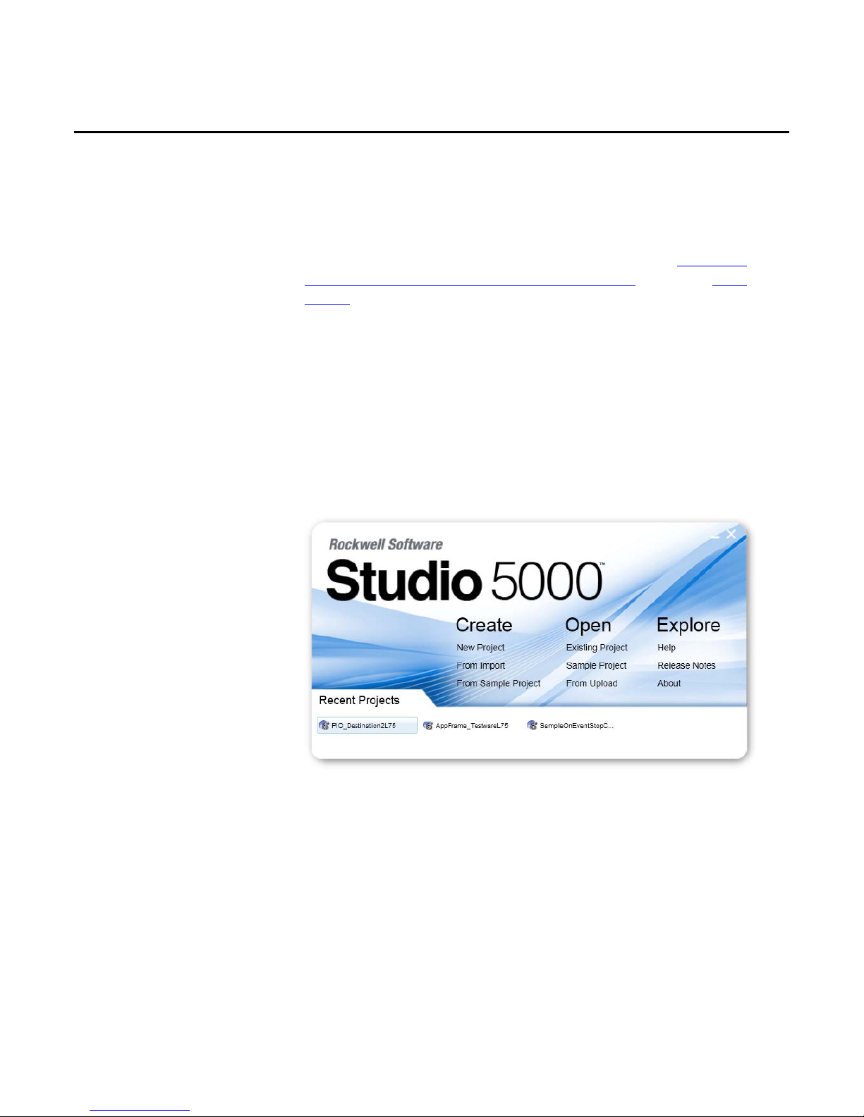
The Studio 5000 Automation Engineering & Design Environment® combines
engineering and design elements into a common environment. The first element is
the Studio 5000 Logix Designer® application. The Logix Designer application is
the rebranding of RSLogix 5000® software and will continue to be the product to
program Logix 5000™ controllers for discrete, process, batch, motion, safety, and
drive-based solutions.
Logix 5000
Rockwell Automation Publication 1756-PM012H-EN-P - February 2018 7
The Studio 5000® environment is the foundation for the future of
Rockwell Automation® engineering design tools and capabilities. The Studio 5000
environment is the one place for design engineers to develop all elements of their
control system.
Page 8
Preface
Provides declarations of conformity, certificates, and other
Additional resources
Legal notices
These documents contain additional information concerning related Rockwell
Automation products.
Resource Description
Industrial Automation Wiring and Grounding Guidelines,
publication 1770-4.1
Product Certifications webpage, available at
http://ab.rockwellautomation.com
Provides general guidelines for installing a Rockwell
Automation industrial system.
certification details.
You can view or download publications at
http://www.rockwellautomation.com/literature. To order paper copies of
technical documentation, contact your local Rockwell Automation distributor or
sales representative.
Copyright notice
Copyright © 2018 Rockwell Automation Technologies, Inc. All Rights Reserved.
Printed in USA.
This document and any accompanying Rockwell Software products are
copyrighted by Rockwell Automation Technologies, Inc. Any reproduction
and/or distribution without prior written consent from Rockwell Automation
Technologies, Inc. is strictly prohibited. Please refer to the license agreement for
details.
End User License Agreement (EULA)
You can view the Rockwell Automation End-User License Agreement ("EULA")
by opening the License.rtf file located in your product's install folder on your hard
drive.
Other Licenses
The software included in this product contains copyrighted software that is
licensed under one or more open source licenses. Copies of those licenses are
included with the software. Corresponding Source code for open source packages
included in this product can be located at their respective web site(s).
You may alternately obtain complete Corresponding Source code by contacting
Rockwell Automation via our Contact form on the Rockwell Automation
website:
http://www.rockwellautomation.com/global/aboutus/contact/contact.page.
Please include "Open Source" as part of the request text.
8 Rockwell Automation Publication 1756-PM012H-EN-P - February 2018
Page 9

Preface
A full list of all open source software used in this product and their corresponding
licenses can be found in the OPENSOURCE folder included with the Release
Notes. The default installed location of these licenses is C:\Program Files
(x86)\Common
Files\Rockwell\Help\<Product>\ReleaseNotes\OPENSOURCE\index.htm.
Trademark Notices
Allen-Bradley, ControlBus, ControlFLASH, Compact GuardLogix, Compact
I/O, ControlLogix, CompactLogix, DCM, DH+, Data Highway Plus,
DriveLogix, DPI, DriveTools, Explorer, FactoryTalk, FactoryTalk Administration
Console, FactoryTalk Alarms and Events, FactoryTalk Batch, FactoryTalk
Directory, FactoryTalk Security, FactoryTalk Services Platform, FactoryTalk
View, FactoryTalk View SE, FLEX Ex, FlexLogix, FLEX I/O, Guard I/O, High
Performance Drive, Integrated Architecture, Kinetix, Logix5000, Logix 5000,
Logix5550, MicroLogix, DeviceNet, EtherNet/IP, PLC-2, PLC-3, PLC-5,
PanelBuilder, PowerFlex, PhaseManager, POINT I/O, PowerFlex, Rockwell
Automation, RSBizWare, Rockwell Software, RSEmulate, Historian, RSFieldbus,
RSLinx, RSLogix, RSNetWorx for DeviceNet, RSNetWorx for EtherNet/IP,
RSMACC, RSView, RSView32, Rockwell Software Studio 5000 Automation
Engineering & Design Environment, Studio 5000 View Designer, SCANport,
SLC, SoftLogix, SMC Flex, Studio 5000, Ultra 100, Ultra 200, VersaView,
WINtelligent, XM, SequenceManager are trademarks of Rockwell Automation,
Inc.
Any Rockwell Automation logo, software or hardware product not mentioned
herein is also a trademark, registered or otherwise, of Rockwell Automation, Inc.
Other Trademarks
CmFAS Assistant, CmDongle, CodeMeter, CodeMeter Control Center, and
WIBU are trademarks of WIBU-SYSTEMS AG in the United States and/or
other countries. Microsoft is a registered trademark of Microsoft Corporation in
the United States and/or other countries. ControlNet is a trademark of
ControlNet International. DeviceNet is a trademark of the Open DeviceNet
Vendors Association (ODVA). Ethernet/IP is a trademark of ControlNet
International under license by ODVA.
All other trademarks are the property of their respective holders and are hereby
acknowledged.
Warranty
This product is warranted in accordance with the product license. The product’s
performance may be affected by system configuration, the application being
performed, operator control, maintenance, and other related factors. Rockwell
Automation is not responsible for these intervening factors. The instructions in
Rockwell Automation Publication 1756-PM012H-EN-P - February 2018 9
Page 10

Preface
this document do not cover all the details or variations in the equipment,
procedure, or process described, nor do they provide directions for meeting every
possible contingency during installation, operation, or maintenance. This
product’s implementation may vary among users.
This document is current as of the time of release of the product; however, the
accompanying software may have changed since the release. Rockwell Automation,
Inc. reserves the right to change any information contained in this document or
the software at any time without prior notice. It is your responsibility to obtain the
most current information available from Rockwell when installing or using this
product.
Environmental compliance
Rockwell Automation maintains current product environmental information on
its website at
http://www.rockwellautomation.com/rockwellautomation/about-
us/sustainability-ethics/product-environmental-compliance.page
Contact Rockwell Automation
Customer Support Telephone — 1.440.646.3434
Online Support — http://www.rockwellautomation.com/support/
10 Rockwell Automation Publication 1756-PM012H-EN-P - February 2018
Page 11
Introduction to Controller
Supported data types
Messages
Chapter 1
Controller messages
This section describes how to transfer (send or receive) data between controllers
by executing a message (MSG) instruction. It explains cache connections and
buffers so you can correctly program the controller.
The following data types are supported when sending CIP messages.
• SINT
• INT
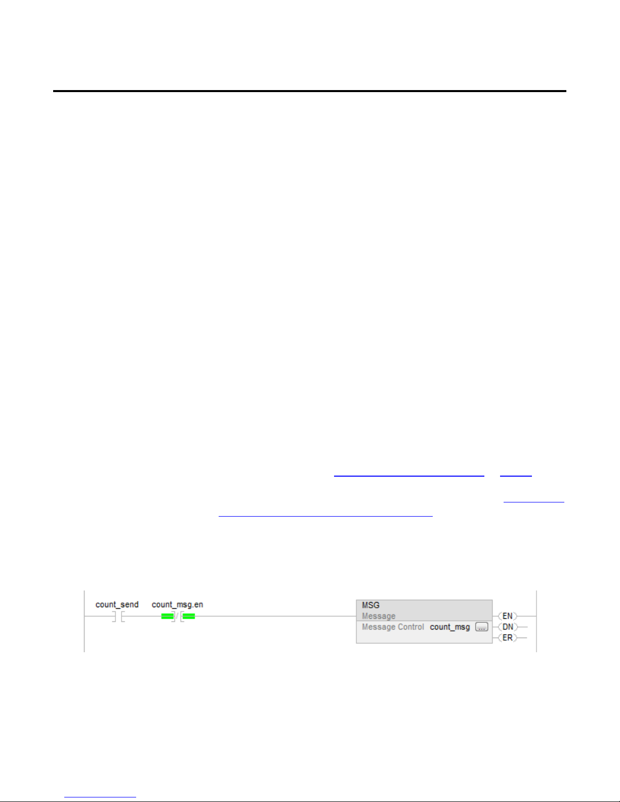
Example: Execute a message (MSG) instruction
If count_send = 1
and count_msg.EN = 0 (MSG instruction is not enabled)
then execute a MSG instruction that sends data to another controller.
• DINT
• LINT
• REAL
In addition, you can send a message with any structure type that is predefined,
module-defined, or user-defined.
For more information, see "Convert between INTs and DINTs on page 18
For complete details on programming a message instruction, see the LOGIX 5000
Controllers General Instruction Reference Manual, publication 1756-RM003.
".
Rockwell Automation Publication 1756-PM012H-EN-P - February 2018 11
Page 12
Chapter 1
Controller messages
Message Queue
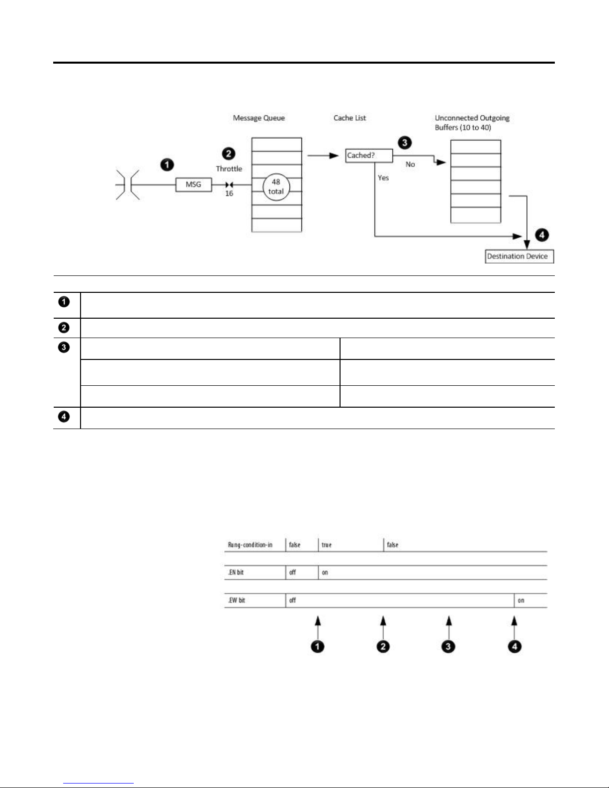
This diagram shows how the controller processes MSG instructions.
Description
The controller scans the MSG instruction and its rung-condition-in goes true. The message passes to a throttle that has 16 positions. If the throttle is full, the message
remains enabled but is held until another controller scan.
The System-overhead time slice executes and the message is pulled from the throttle to the message queue.
If the MSG instruction Then the MSG instruction
Does not use a connection or the connection was not previously cached Uses an unconnected buffer to establish communication with the
destination device.
Uses a connection and the connection is cached Does not use an unconnected buffer.
Communication occurs with the destination device.
The message queue holds up to 48 MSG instructions, including those that you
configure as a block-transfer read or block-transfer write. When the queue is full,
an instruction tries to enter the queue on each subsequent scan of the instruction,
as shown in the following illustration.
12 Rockwell Automation Publication 1756-PM012H-EN-P - February 2018
Page 13

Controller messages
Chapter 1
(1) CIP data table read or write messages can be connected o r unconnected. However for most applications, it is recommended you leave CIP data table read or write
Cache list
Description
&
The controller scans the MSG instruction.
The rung-condition-in for the MSG instruction is true.
The EN bit is set.
The MSG instruction attempts to enter the queue but 16 throttle positions exist. If all 16 are filled and a 17th message is executed, the message is enabled.
The EW bit remains cleared.
The controller scans the MSG instruction.
The rung-condition-in for the MSG instruction is false.
The EN bit remains set.
The MSG instruction attempts to pass through the throttle, but no open positions exist yet.
The EW bit remains cleared.
The controller scans the MSG instruction.
The MSG instruction attempts to enter the queue. This time the throttle position is open and the message can pass to the message queue.
The EW bit is set.
Depending on how you configure a MSG instruction, it may use a connection to
send or receive data.
This type of message And this communication method Uses a connection
CIP data table read or write — Your option
PLC-2, PLC-3, PLC-5, or SLC (all types)
CIP generic — Your option
Block-transfer read or write — Yes
messages connected.
(2) CIP generic messages can be connected or unco nnected. However for most application s, it is recommended you leave CIP generic messages u nconnected, unless you
want to use the Large Connection option.
CIP
CIP with Source ID
DH+ Yes
No
(1)
(2)
If a MSG instruction uses a connection, you have the option to leave the
connection open (cache) or close the connection when the message is done
transmitting.
If you Then
Cache the connection The connection stays open after the MSG instruction is done. This optimizes
execution time. Opening a connection each time the message executes increases
execution time.
Do not cache the connection The connection closes after the MSG instruction is done. This frees up that
connection for other uses.
Rockwell Automation Publication 1756-PM012H-EN-P - February 2018 13
Page 14

Chapter 1
Controller messages
•
The controller has the following limits on the number of connections that you can
cache.
If you have this software version and firmware
revision
11.x or earlier
12.x or later Up to 32 connections.
Then you can cache
Block transfer messages for up to 16 connections.
• Other types of messages for up to 16 connections.
If several messages go to the same device, the messages may be able to share a
connection.
If the MSG instructions are to And they are Then
Different devices — Each MSG instruction uses 1 connection.
The same device, cached, and not a large connection Enabled simultaneously (same scan) Each MSG instruction uses 1 connection and 1 cached
buffer.
Not enabled simultaneously All MSG instructions use 1 connection and 1 cached buffer.
They share the connection and the buffer.
The same device, cached, and a large connection Enabled simultaneously (same scan) Each MSG instruction uses 1 connection and 1 cached
buffer.
Not enabled simultaneously All MSG instructions use 1 connection and 1 cached buffer.
They share the connection and the buffer.
Example: Share a connection
• If the controller alternates between sending a block-transfer read message and a block-transfer write message to the same module, then together the
messages count as one connection. Caching both messages counts as one on the cached buffer.
• If the controller sends 10 cached connected messages to the same bridge module (for example, 1756-EN2T) where 7 utilize a standard connection (large
connection unchecked) and 3 utilize a large connection, then the 7 standard connection messages all utilize one cached connection. The 3 large connection
messages all utilize another cached connection. In total, the 10 messages use 2 cached connections.
14 Rockwell Automation Publication 1756-PM012H-EN-P - February 2018
Page 15

Controller messages
Chapter 1
•
ControlLogix 5580, Compact GuardLogix 5380, and GuardLogix 5580 controllers, enter an MSG tag as either
5 or SLC 500 controller, and it transfers integers (not REALs),
Unconnected buffers
Guidelines
To establish a connection or process unconnected messages, the controller uses an
unconnected buffer.
Term Definition
Unconnected buffer An allocation of memory that the controller uses to process unconnected communication. The controller performs unconnected communication
when it:
• Establishes a connection with a device, including an I/O module.
• Executes a MSG instruction that does not use a connection.
The controller can have 10 to 40 unconnected buffers.
• The default number is 10.
• To increase the number of unconnected buffers, execute a MSG instruction that reconfigures the number of unconnected buffers.
• Each unconnected buffer uses 1.2 KB of memory.
• If all unconnected buffers are in use when an instruction leaves the message queue, an error occurs and data does not transfer.
If a MSG instruction uses a connection, the instruction uses an unconnected
buffer when it first executes to establish a connection. If you configure the
instruction to cache the connection, it no longer requires an unconnected buffer
once the connection is established.
As you plan and program your MSG instructions, follow these guidelines.
Guideline Details
For each MSG instruction, create a control tag.
Keep the source and destination data at the controller scope.
If your message is to a device that uses 16-bit integers, such as a
PLCuse a buffer of INTs in the message and DINTs throughout the
project.
Cache the connection for those MSG instructions that execute
most frequently, up to the maximum number permissible for
your controller revision.
If you want to enable more than 16 MSGs at one time, use a
management strategy to ensure some MSG instructions are not
delayed entering the queue.
Data type = MESSAGE
• Scope = controller
• The tag cannot be part of an array or a user-defined data type.
A MSG instruction can access only tags that are in the Controller Tags folder (controller scope).
Tip: On CompactLogix 5370, ControlLogix 5570, Compact GuardLogix 5370, and GuardLogix 5570
controllers, enter an MSG tag only as a controller scope tag.
In versions 31 and later of the Logix Designer application, on CompactLogix 5380, CompactLogix 5480,
a controller scope or a Program Local scope tag.
Logix 5000 controllers execute more efficiently and use less memory when working with 32-bit integers
(DINTs).
See Convert Between INTs and DINTs on page 18.
Execution time is optimized when the contr oller does not open a connection each time the message
executes.
To guarantee the execution of each message, use one of these options:
• Enable each message in sequence.
• Enable the messages in groups.
• Program a message to communicate with multiple devices.
• Program logic to coordinate the execution of messages.
Rockwell Automation Publication 1756-PM012H-EN-P - February 2018 15
Page 16

Chapter 1
Controller messages
Get or set the number of
Get the number of unconnected
Set the number of unconnected
Keep the number of unconnected and uncached MSGs less than
the number of unconnected buffers.
The controller can have 10 to 40 unconnected buffers. The default number is 10.
• If all unconnected buffers are in use when an instruction leaves the message queue, an error occurs, the
data is not transferred.
• You can increase the number of unconnected buffers (up to 40), provided you continue to adhere to the
previous guideline.
• To increase the number of unconnected buffers, see "Get or Set the Number of Unconnected Buffers
page 16".
To determine or change the number of unconnected buffers, use a MSG
unconnected buffers
instruction.
• The range is 10 to 40 unconnected buffers.
• The default number is 10.
• Each unconnected buffers uses 1.1 KB of memory.
To determine the number of unconnected buffers that are currently available,
buffers
On this tab For this item Type or choose
Configuration Message Type CIP Generic
Service Type Custom
Service Code 3
Class 304
Instance 1
Attribute 0
Source Element so urce_array where data type = SINT[4]
Source Length (bytes) 4 (Write 4 SINTs.)
Destination Element destinatio n_array where data type = SINT[10] (Leave all values = 0.)
Communication Path 1, slot_number_o f_controller
configure a Message (MSG) instruction as follows.
In this element Enter
source_array[0] 1
source_array[1] 0
source_array[2] 17
source_array[3] 0
destination_a rray[6] = current number of unconnected buffers
on
buffers
16 Rockwell Automation Publication 1756-PM012H-EN-P - February 2018
As a starting value, set the number of unconnected buffers equal to the number of
unconnected and uncached messages enabled at one time plus 5. The additional 5
buffers provide a cushion in case you underestimate the number of messages that
are enabled at once.
Page 17

Controller messages
Chapter 1
To change the number of unconnected buffers of the controller, configure a
Message (MSG) instruction as follows.
On this tab For this item Type or select
Configuration Message Type CIP Generic
Service Type Custom
Service Code 4
Class 304
Instance 1
Attribute 0
Source Element so urce_array where data type = SINT[8]
In this element Enter
source_array[0] 1
source_array[1] 0
source_array[2] 17
source_array[3] 0
source_array[4] Number of unconnected buffers
that you want.
source_array[5] 0
source_array[6] 0
source_array[7] 0
Source Length (bytes) 8 (Write 8 SINTs.)
Destination Element destinatio n_array where data type = SINT[6] (Leave all the values = 0.)
Communication Path THIS
or for earlier Logix 5000 controllers: 1, slot_number_of_controller
Rockwell Automation Publication 1756-PM012H-EN-P - February 2018 17
Page 18

Chapter 1
Controller messages
Convert between INTs and
Example: Set the number of unconnected b uffers
If S:FS = 1 (first scan)
then set the number of unconnected buffers for the controller.
Source_Array[0] = 1
Source_Array[0] = 1
Source_Array[1] = 0
Source_Array[2] = 17
Source_Array[3] = 0
Source_Array[4] = 12 (The number of unconnected buffers that you want. In this example, we want 12 buffers.)
If UCB_Set.EN = 0 (MSG instruction is not already enabled)
then MSG instruction sets the number of unconnected buffers = Source_Array[4].
DINTs
Tag Name Type Description
UCB_Set MESSAGE Control tag for the MSG instruction.
Source_Array SINT[8] Source values for the MSG instruction, including the number of unconnected buffers
that you want.
In the Logix 5000 controller, use the DINT data type for integers whenever
possible. Logix 5000 controllers execute more efficiently and use less memory
when working with 32-bit integers (DINTs).
If your message is to a device that uses 16-bit integers, such as a PLC-5 or SLC 500
controller, and it transfers integers (not REALs), use a buffer of INTs in the
message and DINTs throughout the project. This increases the efficiency of your
project.
18 Rockwell Automation Publication 1756-PM012H-EN-P - February 2018
Page 19

Controller messages
Chapter 1
Read 16-bit integers
Data from the
device
Word 1
Word 2
Word 3
Buffer of INTs
INT_Buffer[0]
INT_Buffer[1]
INT_Buffer[2]
Description
The Message (MSG) instruction reads 16-bit integers (INTs) from the device and stores them in a temporary array of INTs.
A File Arith/Logical (FAL) instruction converts the INTs to DINTs for use by other instructions in your project.
Write 16-bit integers
DINTs for use in the
project
DINT_Array[0]
DINT_Array[1]
DINT_Array[2]
DINTs from the project
DINT_Array[0]
DINT_Array[1]
DINT_Array[2]
Description
An FAL instruction converts the DINTs from the Logix 5000 controller to INTs.
The MSG instruction writes the INTs from the temporary array to the device.
Buffer of INTs
INT_Buffer[0]
INT_Buffer[1]
INT_Buffer[2]
Data for the
device
Word 1
Word 2
Word 3
Rockwell Automation Publication 1756-PM012H-EN-P - February 2018 19
Page 20

Chapter 1
Controller messages
Example:
Read integer values from a PLC-5 controller
If Condition_1 = 1
and Msg_1.EN = 0 (MSG instruction is not enabled)
then read 3 integers from the PLC-5 controller and store them in INT_Buffer (3 INTs).
If Msg_1.DN =1 (MSG instruction has read the data)
then reset the FAL instruction.
The FAL instruction sets DINT_Array = INT_Buffer. This converts the values to 32-bit integers (DINTs).
Example:
If Control_2.DN = 1 (FAL instruction has converted the DINTs to INTs)
Write integer values to a PLC-5 controller
If Condition_2 = 1
then reset the FAL instruction.
The FAL instruction sets INT_Buffer = DINT_Array. This converts the values to 16-bit integers (INTs).
and Msg_2.EN = 0 (MSG instruction is not enabled)
then write the integers in INT_Buffer (3 INTs) to the PLC-5 controller.
20 Rockwell Automation Publication 1756-PM012H-EN-P - February 2018
Page 21

Controller messages
Chapter 1
Rockwell Automation Publication 1756-PM012H-EN-P - February 2018 21
Page 22

Page 23

Introduction
Message manager logic
Chapter 2
Manage multiple messages
You can use ladder logic to send groups of message (MSG) instructions in
sequence.
• To be processed, each MSG instruction must enter the message queue.
• The queue holds 48 MSGs.
• If more than 16 MSGs are enabled at one time, the message throttle
prevents some of the messages from entering the message queue. If this
occurs, the MSG is held until room exists on the queue for the controller to
process the MSG. On each subsequent scan of the MSG, it checks the queue
to see if room exists.
Example:
The message manager logic lets you control the number of MSGs that are enabled
at one time and enable subsequent MSGs in sequence. In this way, MSGs enter
and exit the queue in order and do not need to wait for room on the queue to
become available.
The message manager logic sends three groups of MSGs. Use as many groups as
needed to include all your MSGs.
The Msg_Group tag controls the enabling of each MSG.
• The tag uses the DINT data type.
• Each bit of the tag corresponds to a group of MSGs. For example,
Msg_Group.0 enables and disables the first group of MSGs (group 0).
Message manner logic
To make the example easier to follow, each group contains only two MSGs. In your project, use more MSGs in each group, such as five.
Initialize the logic
If S:FS = 1 (first scan)
then initialize the MSGs:
Msg_Group = 0, which disables all MSGs.
Msg_Group.0 =1, which enables the first group of MSGs.
Rockwell Automation Publication 1756-PM012H-EN-P - February 2018 23
Page 24

Chapter 2
Manage multiple messages
Restart the sequence
If the MSGs in group 2 (last group) are currently enabled (Msg_Group.2 = 1)
and Msg_4 is in the state of done or error
and Msg_5 is in the state of done or error
then restart the sequence of MSGs with the first group:
Msg_Group.2 = 0. This disables the last group of MSGs.
Msg_Group.0 = 1. This enables the first group of MSGs.
Send the first group of MSGs
If Msg_Group.0 changes from 0 -> 1 then
send Msg_0.
send Msg_1.
Because a MSG instruction is a transitional instruction, it executes only when its rung-condition-in changes from false to true.
Enable the second group of MSGs
If the MSGs in group 0 are currently enabled (Msg_Group.0 = 1)
and Msg_0 is in the state of done or error
and Msg_1 is in the state of done or error
then:
Msg_Group.0 = 0. This disables the current group of MSGs.
Msg_Group.1 = 1. This enables the next group of MSGs.
24 Rockwell Automation Publication 1756-PM012H-EN-P - February 2018
Page 25

Manage multiple messages
Chapter 2
Send the second group of MSGs
If Msg_Group.1 changes from 0 -> 1 then
send Msg_2.
send Msg_3.
Enable the next group of MSGs
If the MSGs in group 1 are currently enabled (Msg_Group.1 = 1)
and Msg_2 is in the state of done or error
and Msg_3 is in the state of done or error
then:
Msg_Group.1 = 0. This disables the current group of MSGs.
Msg_Group.2 = 1. This enables the next group of MSGs.
Rockwell Automation Publication 1756-PM012H-EN-P - February 2018 25
Page 26

Chapter 2
Manage multiple messages
Send the next group of MSGs
If Msg_Group.1 changes from 0 -> 1 then
send Msg_2.
send Msg_3.
26 Rockwell Automation Publication 1756-PM012H-EN-P - February 2018
Page 27
Introduction
Chapter 3
Send a message to multiple controllers
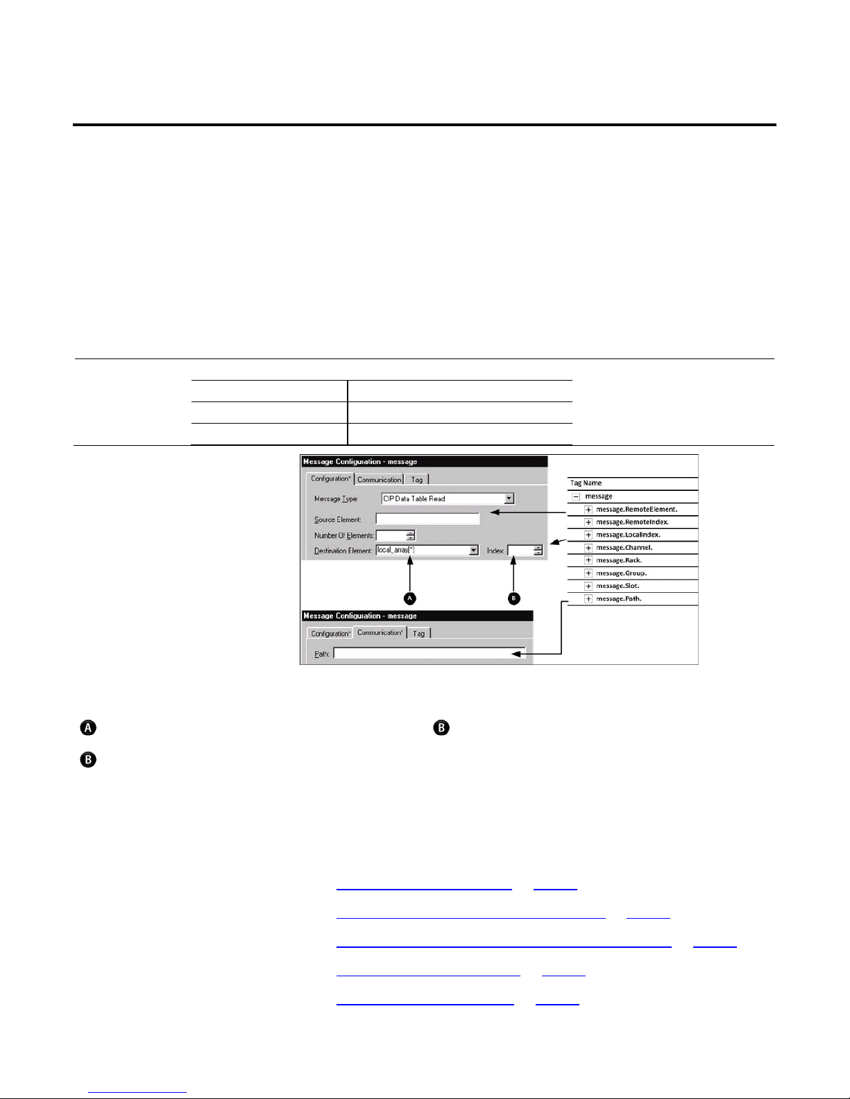
Program a single message instruction to communicate with multiple controllers.
To reconfigure a MSG instruction during runtime, write new values to the
members of the MESSAGE data type.
Important:
In the MESSAGE data type, the RemoteElement member stores the tag name or address of the data in the controller that receives the message.
If the message Then the RemoteElement is the
Reads data Source element
Writes data Destination element
If using an asterisk [*] to designate the element number of the array, the value in provides the element number.
The Index box is available only when using an asterisk [*] in Source Element or Destination Element. The instruction substitutes the value of Index for the asterisk
[*].
Rockwell Automation Publication 1756-PM012H-EN-P - February 2018 27
Complete the following to send a message to multiple controllers:
• Set Up the I/O Configuration on page 28
• Define Your Source and Destination Elements on page 29
• Create the MESSAGE_ CONFIGURATION Data Type on page 30
• Create the Configuration Array on page 31
• Get the Size of the Local Array on page 32
Page 28

Chapter 3
Send a message to multiple controllers
Configure the I/O
• Load the Message Properties for a Controller on page 33
• Configure the Message on page 34
• Step to the Next Controller on page 34
• Restart the Sequence on page 35
Tip:
To copy the above components from a sample project, open the C:\Users\Public\Public Documents\Studio 5000\Samples\ENU\v<current_project>\Rockwell
Automation folder.
configuration
Although not required, it is recommended that you add the communication
modules and remote controllers to the I/O configuration of the controller. This
makes it easier to define the path to each remote controller.
For example, once you add the local communication module, the remote
communication module, and the destination controller, clicking Browse lets you
select the destination.
Message Path Browser
Path: peer_controller
peer_controller
I/O Configuration
[0] 1756-CNB/x Local_CNB
2 [0] 1756-CNB/x chassis_b
[1] 1756-L55/x
peer_controller
28 Rockwell Automation Publication 1756-PM012H-EN-P - February 2018
Page 29

Send a message to multiple controllers
Chapter 3
Define your source and
destination elements
An array stores the data that is read from or written to each remote controller.
Each element in the array corresponds to another remote controller.
1. Use the following worksheet to organize the tag names in the local and
remote controllers.
Name of Remote
Controller
Tag or Address of Data in Remo te
Controller
Tag in This Controller
local_array[0]
local_array[1]
local_array[2]
local_array[3]
Rockwell Automation Publication 1756-PM012H-EN-P - February 2018 29
2. Create the local_array tag, which stores the data in this controller.
Tag Name Type
local_array data_type [length]
where:
data_type is the data type of the data that the message sends or receives, such as
DINT, REAL, or STRING.
length is the number of elements in the local array.
Page 30

Chapter 3
Send a message to multiple controllers
Create the MESSAGE_
CONFIGURATION data type
Create a user-defined data type to store the configuration variables for the message
to each controller.
• Some of the required members of the data type use a string data type.
• The default STRING data type stores 82 characters.
• If your paths or remote tag names or addresses use less than 82 characters,
you have the option of creating a new string type that stores fewer
characters. This lets you conserve memory.
• To create a string type, click File > New Component > String Type.
• If you create a string type, use it in place of the STRING data type.
To store the configuration variables for the message to each controller, expand the
Assets > Data Types folder, right-click User Defined, and select New Data Type
to create the following user-defined data type.
30 Rockwell Automation Publication 1756-PM012H-EN-P - February 2018
Data Type: MESSAGE_CONFIGURATION
Name: MESSAGE_CONFIGURATION
Description: Configuration properties for a message to another controller
Members
Name Data Type Style Description
Path
RemoteElement
STRING
STRING
Page 31

Send a message to multiple controllers
Chapter 3
(1) Number indicates the number of controll ers to send the message
Create the configuration
array
Store the configuration properties for each controller in an array. Before each
execution of the MSG instruction, your logic loads new properties into the
instruction. This sends the message to another controller.
1. To store the configuration properties for the message, create the following
array.
Tag Name Type Scope
message_config MESSAGE_CONFIGURATION[number]
(1)
Any
2. In the message_config array, enter the path to the first controller that
receives the message.
Rockwell Automation Publication 1756-PM012H-EN-P - February 2018 31
Page 32

Chapter 3
Send a message to multiple controllers
Get the size of the local
3. In the message_config array, enter the tag name or address of the data in the
first controller to receive the message.
4. Enter the path and remote element for each additional controller.
Tag Name Value
message_config {…}
message_config[0] {…}
message_config[0].Path
message_config[0].RemoteElement
message_config[1] {…}
message_config[1].Path
message_config[1].RemoteElement
array
32 Rockwell Automation Publication 1756-PM012H-EN-P - February 2018
The SIZE instruction:
• Counts the number of elements in local_array.
• Counts the number of elements in Dimension 0 of the array. In this case,
that is the only dimension.
Local_array_length (DINT) stores the size (number of elements) of local_array.
This value tells a subsequent rung when the message is sent to all controllers and to
start with the first controller again.
Page 33

Send a message to multiple controllers
Chapter 3
Load the message
1. The XIO instruction conditions the rung to continuously send the message.
properties for a controller
2. The first COP instruction loads the path for the message. The value of
index determines which element the instruction loads from message_config.
The instruction loads one element from message_config.
3. The second COP instruction loads the tag name or address of the data in
the controller that receives the message. The value of index determines
which element the instruction loads from message_config. The instruction
loads one element from message_config.
Rockwell Automation Publication 1756-PM012H-EN-P - February 2018 33
Page 34

Chapter 3
Send a message to multiple controllers
Configure the message
Step to the next controller
The following table explains how to configure the message.
On this tab If you want to For this item Type or select
Configuration Read (receive) data from the other
controllers
Write (send) data to the other
controllers
Communication — Path Path to the first controller
Message Type The read-type that corresponds to the other controllers
Source Element Tag or address that contains the data in the first controller
Number Of Elements 1
Destination Element local_array[*]
Index 0
Message Type The write-type that corresponds to other controllers
Source Element local_array[*]
Index 0
Number Of Elements 1
Destination Element Tag or address that contains the data in the first controller
Cache Connections
Clear the Cache Connections check box (more efficient since this procedure
continuously changes the path of the message)
After the MSG instruction sends the message, the following actions occur.
1. The first ADD instruction increments the index. This lets the logic load the
configuration properties for the next controller into the MSG instruction.
2. The second ADD instruction increments the LocalIndex member of the
MSG instruction. This lets the logic load the value from the next controller
into the next element of local_array.
34 Rockwell Automation Publication 1756-PM012H-EN-P - February 2018
Page 35

Send a message to multiple controllers
Chapter 3
Restart the sequence
When the index equals the local_array_length, the controller sends the message to
all other controllers.
1. The first CLR instruction sets the index equal to 0. This lets the logic load
the configuration properties for the first controller into the MSG
instruction and start the sequence of messages again.
2. The second CLR instruction sets the LocalIndex member of the MSG
instruction equal to 0. This lets the logic load the value from the first
controller into the first element of local_array.
Rockwell Automation Publication 1756-PM012H-EN-P - February 2018 35
Page 36

Page 37

A
Index
array
controller configuration 28
B
block transfer
guidelines 15
buffer
for unconnected messages 14, 16
convert between 16 and 32-bit data 18
example illustration 11
limits 12
manage multiple messages 21
processing 11
queue 12
to a single controller 11
to multiple controllers 25
unconnected buffer 14, 16
P
C
cache
connection 13
communicate
message instruction 11
other controllers 11
connection
cache 13
controller
message properties 30
messages 11
D
data type
convert data 18
message configuration 27
G
guidelines
messages 15
processing
message 11
Q
queue
message 12
T
tag
guidelines for messages 15
organize for message 11
L
ladder logic
manage messages 21
M
message
cache connection 13
controller 11
Rockwell Automation Publication 1756-PM012H-EN-P - February 2018 37
Page 38

Rockwell Automation support
Rockwell Automation provides technical information on the web to assist you in using its products. At
http://www.rockwellautomation.com/support
can also visit our Support Center at https://rockwellautomation.custhelp.com for software updates, support chats and forums, technical
information, FAQs, and to sign up for product notification updates.
In addition, we offer multiple support programs for installation, configuration, and troubleshooting. For more information, contact your local
distributor or Rockwell Automation representative, or visit http://www.rockwellautomation.com/services/online-phone
Installation assistance
If you experience a problem within the first 24 hours of installation, review the information that is contained in this manual. You can contact
Customer Support for initial help in getting your product up and running.
United States or Canada 1.440.646.3434
Outside United States or Canada Use the Worldwide Locator available at http: //www.rockwellautomation.com/locations, or contact your local Rockwell
New product satisfaction return
you can find technical and application notes, sample code, and links to software service packs. You
.
Automation representative.
Rockwell Automation tests all of its products to ensure that they are fully operational when shipped from the manufacturing facility. However, if
your product is not functioning and needs to be returned, follow these procedures.
United States Contact your distributor. You must provide a Customer Support case number (call the phone number above to obtain one) to
your distributor to complete the return process.
Outside United States Please contact your local Rockwell Automation representative for the return procedure.
Documentation feedback
Your comments will help us serve your documentation needs better. If you have any suggestions on how to improve this document, complete the
feedback form, publication RA-DU002
.
Rockwell Automation Publication 1756-PM012H-EN-P - February 2018
Supersedes Publicat ion 1756-PM012G-EN-P - June 2016 Copyright © 2018 Rockwell Automation Technologies, Inc. All Right s Reserved. Printed in the U.S.A.
 Loading...