

Allen-Bradley 1746-IB16, 1746-IA4, 1746-IC16, 1746-IB8, 1746-IH16 Installation Instructions Manual
...Page 1

Discrete I/O Modules
(Catalog Number 1746 Series)
Installation In st ru ct io ns
Input Module Catalog Numbers:
1746-IA4, -IA8, -IA16, -IB8, -IB16, -IC16, -IG16, -IH16, -IM4,
-IM8, -IM16,
-IN16, -ITB16, -ITV16, -IV8, -IV16
Output Module Catalog Numbers:
1746-OA8, -OA16, -OAP12, -OB8, -OB6EI, -OB16, -OB16E,
-OBP8,
-OBP16, -OG16, -OV8, -OV16, -OVP16, -OW4, -OW8, OW16, -OX8
Combination Input/Output Module Catalog Numbers:
1746-IO4, -IO8, -IO12, -IO12DC
Publication 1746-IN005A-US-P
Page 2
2 Discrete I/O Module s
Important User Information
Because of the variety of uses for th e products described in this publication, those
responsible for the application and use of this control equipment must satisfy
themselves that all necessary steps have been taken to assure that each
application and use meets all performance and safety requirements, including any
applicable laws, regulations, codes and standards.
The illustrations, charts, sample programs and layout examples shown in this
guide are intended solely for purposes of example. Since there are many
variables and requirements associated with any particular installation, AllenBradley does not assume resp onsibility or liability (to in clude intellectual
property liability) for actual use based upon the examples shown in this
publication.
Allen-Bradley publication SGI-1.1, Safety Guidelines for the Application,
Installation, and M ain tenance of Solid-State Control (available from your local
Allen-Bradley office), describes some important differences between solid-state
equipment and electromechanical devices that should be taken into consideration
when applying products such as those described in this publication.
Reproduction of the cont ent s of t his copy ri ghted pub licati on , in whol e or in part ,
without written permission of A llen-Bradley Company, Inc., is prohibited.
Throughout these installation instructions we use notes to make you aware of
safety considerations:
ATTENTION: Identifies information about practices or
circumstances that can lead to personal injury or death, property
!
Attention statements hel p you to:
• identify a hazard
• avoid the hazard
• recognize the consequences
IMPORTANT : Identifies information that is critical for successful ap plication and
damage or economic loss.
understanding of the product.
Publication 1746-IN005A-US-P
Page 3

Discrete I/O Modules 3
Table of Contents
Overview . . . . . . . . . . . . . . . . . . . . . . . . . . . . . . . . . . . . . . . . . . . . . . . . .4
Hazardous Location Considerations. . . . . . . . . . . . . . . . . . . . . . . . . . . . .4
Environnements Dangereux. . . . . . . . . . . . . . . . . . . . . . . . . . . . . . . . . . .4
Installation . . . . . . . . . . . . . . . . . . . . . . . . . . . . . . . . . . . . . . . . . . . . . . . .5
Specifications . . . . . . . . . . . . . . . . . . . . . . . . . . . . . . . . . . . . . . . . . . . . .6
General I/O . . . . . . . . . . . . . . . . . . . . . . . . . . . . . . . . . . . . . . . . . . . .6
Heat Dissipation . . . . . . . . . . . . . . . . . . . . . . . . . . . . . . . . . . . . . . . .7
Input Modules - ac . . . . . . . . . . . . . . . . . . . . . . . . . . . . . . . . . . . . . .9
Input Modules - dc . . . . . . . . . . . . . . . . . . . . . . . . . . . . . . . . . . . . .11
Output Modules - ac . . . . . . . . . . . . . . . . . . . . . . . . . . . . . . . . . . . .16
Output Modules - dc . . . . . . . . . . . . . . . . . . . . . . . . . . . . . . . . . . . .17
Relay Contact Output Modules . . . . . . . . . . . . . . . . . . . . . . . . . . . .24
Relay Contact Ratings . . . . . . . . . . . . . . . . . . . . . . . . . . . . . . . . . .25
Input/Output Combination Modules . . . . . . . . . . . . . . . . . . . . . . . .26
Octal Label Kit Installation (for PLC Processors Only) . . . . . . . . . . . . .27
Applying the Octal Filter Label . . . . . . . . . . . . . . . . . . . . . . . . . . . .27
Applying the Octal Door Label . . . . . . . . . . . . . . . . . . . . . . . . . . . .27
Removable Terminal Blocks . . . . . . . . . . . . . . . . . . . . . . . . . . . . . .28
Fuse Protection and Blown Fuse Diagnostics . . . . . . . . . . . . . . . . . . . .29
Fuse Protection (1746-OBP16 and 1746-OVP16) . . . . . . . . . . . . .29
Fuse Protection (1746-OAP12) . . . . . . . . . . . . . . . . . . . . . . . . . . . .29
Blown Fuse Diagnostics . . . . . . . . . . . . . . . . . . . . . . . . . . . . . . . . .29
Processor Operation in Case of Blown Fuse - Processor Continues .
32
Processor Operation in Case of Blown Fuse - Processor Faults . .32
Recovery From Blown Fuse/Processor Fault/Processor Shutdown 34
Replacement Fuse Recommendations . . . . . . . . . . . . . . . . . . . . . .34
Fuse Replacement Procedure . . . . . . . . . . . . . . . . . . . . . . . . . . . .35
Electronically Protected Modules (1746-OB6EI and -OB16E) . . . . . . .36
Electronic Protection . . . . . . . . . . . . . . . . . . . . . . . . . . . . . . . . . . . .36
Auto Reset Operation . . . . . . . . . . . . . . . . . . . . . . . . . . . . . . . . . . .37
Short Circuit/Overload Current Diagnostics . . . . . . . . . . . . . . . . . .37
Recovery From Channel Shutdown . . . . . . . . . . . . . . . . . . . . . . . .37
Wiring Diagrams . . . . . . . . . . . . . . . . . . . . . . . . . . . . . . . . . . . . . . . . . .38
Labeling for SLC/PLC
Input Modules - ac . . . . . . . . . . . . . . . . . . . . . . . . . . . . . . . . . . . . .39
Input Modules - dc . . . . . . . . . . . . . . . . . . . . . . . . . . . . . . . . . . . . .41
Output Modules - ac . . . . . . . . . . . . . . . . . . . . . . . . . . . . . . . . . . . .43
Relay Contact Output Modules . . . . . . . . . . . . . . . . . . . . . . . . . . . .48
®
Systems . . . . . . . . . . . . . . . . . . . . . . . . . .38
Publication 1746-IN005A-US-P
Page 4

4 Discrete I/O Module s
Input/Output Combination Modules . . . . . . . . . . . . . . . . . . . . . . . .50
Publication 1746-IN005A-US-P
Page 5

Discrete I/O Modules 5
Overview
In addition to providing the module’s electrical specifications, this document tells
you how to:
• install the module into a chassis
• wire the module’s terminal block
• install the Octal Filter Label
Hazardous Location Considerations
This equipment is suitable for use in Class I, Division 2, Groups A, B, C, D or
non-hazardous locations only. The following WARNING statement applies to
use in hazardous locations.
WARNING: EXPLOSION HAZARD
• Substitution of components may impair suitability for Class I,
Division 2.
• Do not replace components or disconnect equipment unless
power has been switched off or the area is known to be nonhazardous.
• Do not connect or disconnect components unless power has
been switched off or the area is known to be non-hazardous.
• All wiring must comply with N.E.C. article 501-4(b).
Environnements Dangereux
Cet équipement est conçu pour être utilis é dan s d e s environnements de Classe I,
Division 2, Groupes A, B, C, D ou non dangereux. La mise en garde suivante
s’applique à une utilisation dans des environnements dangereux.
AVERTISSEMENT: DANGER D’EXPLOSION
• La substitution de com posants peut rendre cet équipement
impropre à une utilisation en environnemen t de Classe I,
Division 2.
• Ne pas remplacer de composants ou déconnecter
l'équipement sans s'être assuré que l'alimentation est coupée.
• Ne pas connecter ou déconnecter des composants sans s'être
assuré que l'alimentation est coupée.
Publication 1746-IN005A-US-P
Page 6
6 Discrete I/O Module s
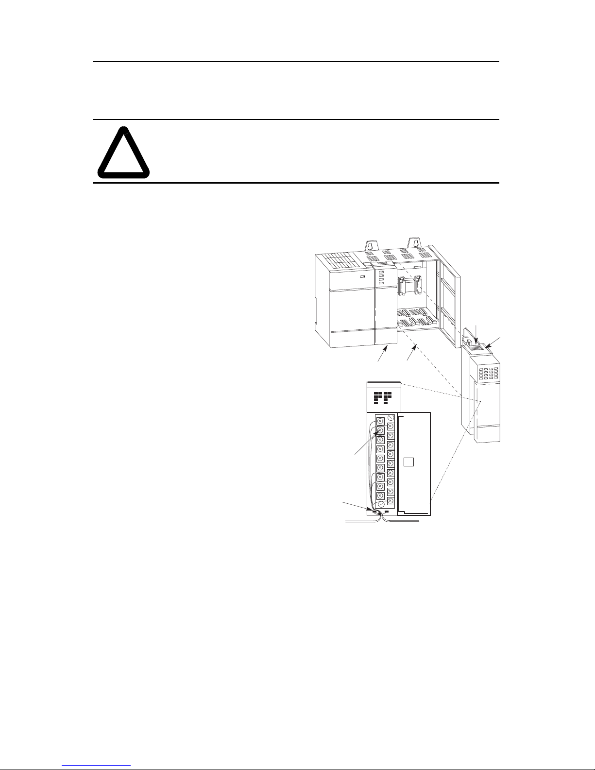
Installation
ATTENTION: Never install, remove, or wire modules with
power applied to chassis.
!
IMPORTANT : The first slot of the chassis is reserved for the processor or the
1747-ASB module.
1. Disconnect power.
2. Align circuit board of
module with chassis card
guide. (A)
3. Slide the module into the
chassis until the bottom tabs
lock into place. (B)
4. Route the wires down and
away from the module,
securing them with the wire
tie. (C)
5. To keep the chassis free
from debris, cover all
unused slots with Card Slot
Filler , catalog n umber 174 6N2.
To remove the module,
press and hold the module
release located on each selflocking tab, and slide the
module out of the chassis
slot. (D)
Slot 1
max. #14 AWG (2 mm
max. 2 wires per terminal
max. torque: 0.9 Nm (8
in-lbs)
2
C
B
D
A
)
Publication 1746-IN005A-US-P
Page 7
Discrete I/O Modules 7
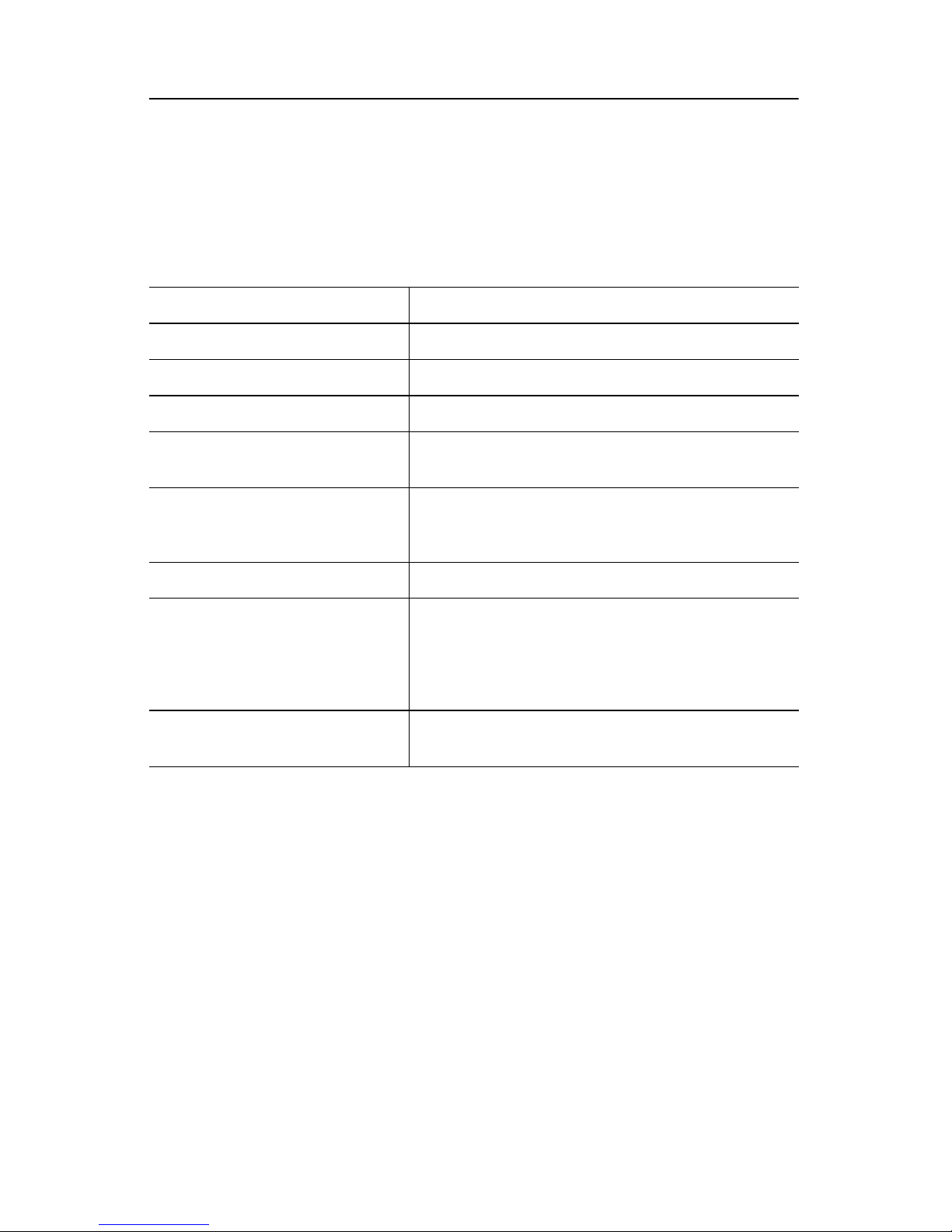
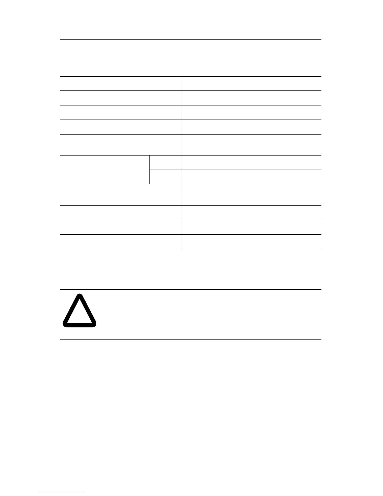
Specifications
General I/O
Table 1: Specifications for All Discrete Modules
Operating Temperature 0°C to 60°C (32°F to 140°F)
(1)
Storage Te mperature -40°C to 85°C (-40°F to 185°F)
Operating Humidity 5% to 95% (noncondensing)
Noise Immunity NEMA standard ICS 2-230
Displacement 0.015 in peak at 5 to 57 Hz
Vibration (Operating)
Acceleration 2.5Gs at 57 to 2000 Hz
30Gs (all modules except relay contact)
Shock (Operating)
10Gs (relay contact modules: -OW, -OX, and
combination I/O modules)
Isolation
(2)
1500V
• UL listed
• CSA certified or C-UL approved as indicated
Agency Certification
by product marking
• CE compliant for all applicable directives
when product or packaging is marked
Hazardous Environment
Class
(3)
Class I, Division 2 Hazardous Environment
UL-A196, CSA, C-UL
(1)Exceptions are indicated with certain modules.
(2)Electro-optical isolation between I/O terminals and control logic.
(3)Some modules are classified Class 1, Division 2 by CSA only or C-UL only as shown in
the specification table for the respective module.
Publication 1746-IN005A-US-P
Page 8

8 Discrete I/O Module s
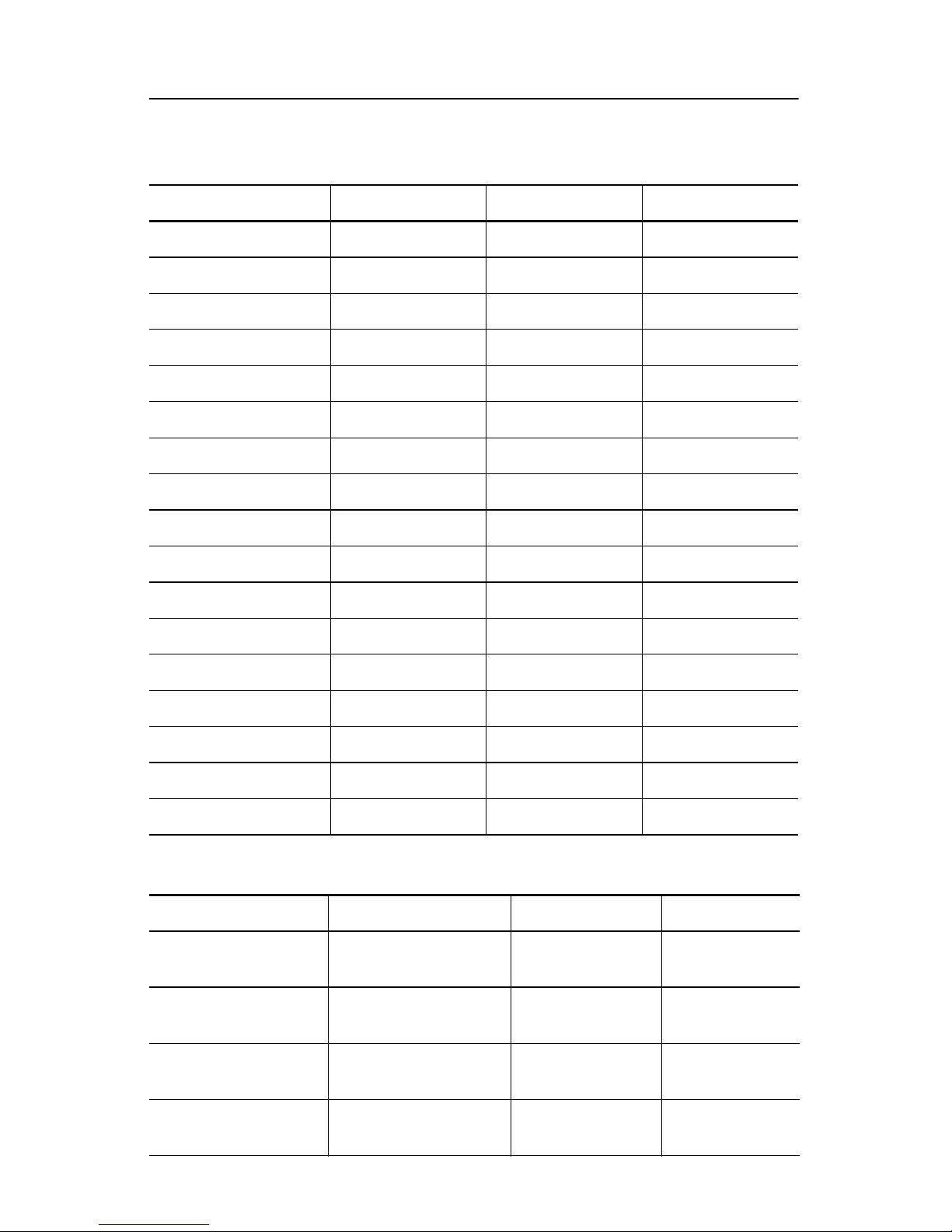
Heat Dissipation
The following tables contain values for the heat dissipated by each I/O module.
Use them to calculate the total amount of heat diss ipated by your SLC 500™
control system. For details on how to calculate total heat dissipation, refer to the
SLC 500 Modular Hardware Style Installation and Operation Manual,
publication 174 7-6 .2. Pl eas e note th e fol lo wing definitions:
• Watts per Point - the heat dissipation that can occur in each field wiring
point when energized at nominal voltage.
• Minimum Watts - the amount of heat dissipation that can occur when there
is no field power present.
• Total Watts - the watts per point multiplied by the number of points, plus the
minimum watts (with all points energized).
Table 2: Input Module Heat Dissipation
Catalog Numbers Watts per Point Minimum Watts Total Watts
1747-IA4 0.27 0.175 1.30
1746-IA8 0.27 0.250 2.40
1746-IA16 0.27 0.425 4.80
1746-IB8 0.20 0.250 1.90
1746-IB16 0.20 0.425 3.60
1746-IC16 0.22 0.425 3.95
1746-IG16 0.02 0.700 1.00
1746-IH16 0.32 0.217 5.17
1746-IM4 0.35 0.175 1.60
1746-IM8 0.35 0.250 3.10
1746-IM16 0.35 0.425 6.00
1746-IN16 0.35 0.425 6.00
1746-ITB16 0.20 0.425 3.60
1746-ITV16 0.20 0.425 3.60
1746-IV8 0.20 0.250 1.90
1746-IV16 0.20 0.425 3.60
Publication 1746-IN005A-US-P
Page 9
Discrete I/O Modules 9
Table 3: Output Module Heat Dissipation
Catalog Numbers Watts per Point Minimum Watts Total Watts
1746-OA8 1.000 0.925 9.00
1746-OA16 0.462 1.850 9.30
1746-OAP12 1.000 1.850 10.85
1746-OB6EI 0.440 0.230 2.90
1746-OB8 0.775 0.675 6.90
1746-OB16 0.388 1.400 7.60
1746-OB16E 0.150 0.675 3.07
1746-OBP8 0.300 0.675 3.08
1746-OBP16 0.310 1.250 6.26
1746-OG16 0.033 0.900 1.50
1746-OV8 0.775 0.675 6.90
1746-OV16 0.388 1.400 7.60
1746-OVP16 0.310 1.250 6.26
1746-OW4 0.133 1.310 1.90
1746-OW8 0.138 2.590 3.70
1746-OW16 0.033 5.170 5.70
1746-OX8 0.825 2.590 8.60
Table 4: Combination Input/Output Module Heat Dissipation
Catalog Numbers Watts per Point Minimum Watts Total Watts
0.27 per input point
1746-IO4
0.75 1.60
0.133 per outp ut poi nt
0.27 per input point
1746-IO8
1.38 3.00
0.133 per outp ut poi nt
1746-IO12
1746-IO12DC
0.27 per input point
2.13 4.60
0.133 per outp ut poi nt
0.20 per input point
1.84 3.90
0.133 per outp ut poi nt
Publication 1746-IN005A-US-P
Page 10
10 Dis cre te I/ O Mod ule s
Input Modules - ac
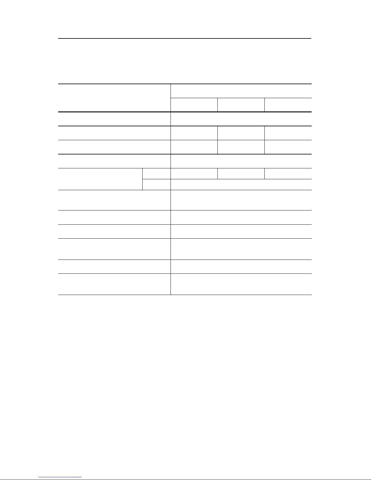
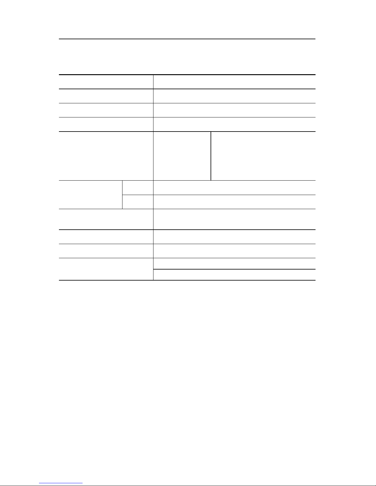
Table 5: Specifications for Input Modules 1746-IA4, -IA8, and -IA16
Catalog Number 1746-
Specification
IA4 IA8 IA16
Voltage Category 100/120V ac Signal Input
Number of Inputs 4816
Points per Common 4816
Operating Voltage 85 to 132V ac at 47 to 63 Hz
(1)
Backplane Current
Consumption
Signal Delay (max.)
5V dc 0.035A 0.050A 0.085A
24V dc 0.0A
on = 35 ms
off = 45 ms
Off State Voltage (max.) 30V ac
Off State Current (max.) 2 mA
Nominal Input Current at 120V
ac
Inrush Current (max.)
(2)
Inrush Current Time Duration
(max.)
(1)Removable Terminal Block.
(2)An ac input device must be compatible with SLC 500 input circuit inrush current. A
current limiting resistor can be used to limit inrush current; however, the operating
characteristics of the ac incircuit will be affected.
12 mA
0.8A
0.5 ms
Publication 1746-IN005A-US-P
Page 11
Discrete I/O Modules 11
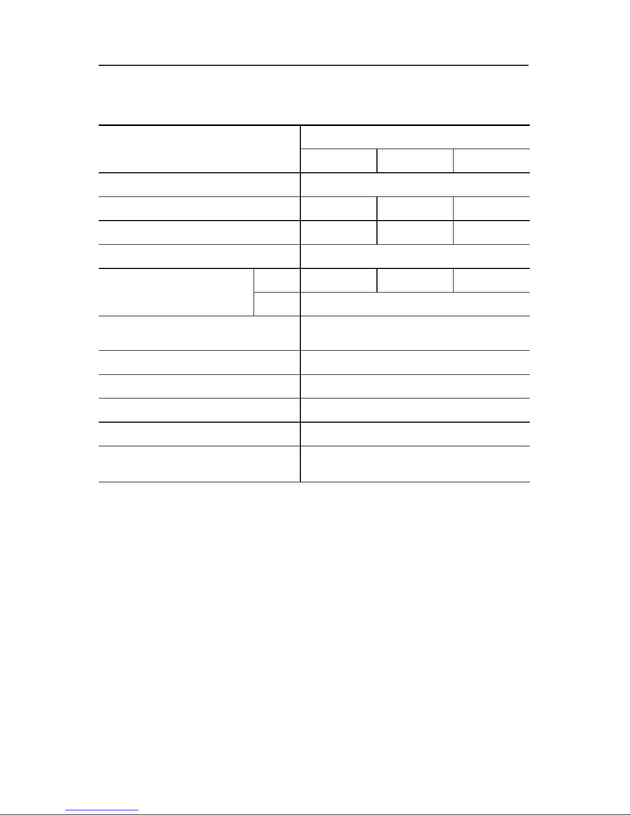
Table 6: Specifications for Input Modules 1746-IM4, -IM8, and -IM16
Catalog Number 1746-
Specification
IM4 IM8 IM16
Voltage Category 200/240V ac Signal Input
Number of Inputs 4816
Points per Common 4816
Operating Voltage 170 to 265V ac at 47 to 63 Hz
(1)
Backplane Current
Consumption
Signal Delay (max.)
5V dc 0.035A 0.050A 0.085A
24V dc 0.0A
on = 35 ms
off = 45 ms
Off State Voltage (max.) 50V ac
Off State Current (max.) 2 mA
Nominal Input Current at 240V ac 12 mA
Inrush Current (max.)
Inrush Current Time Duration
(max.)
(1)Removable Terminal Block.
(2)An ac input device must be compatible with SLC 500 input circuit inrush current. A current
limiting resistor can be used to limit inrush current; however, the operating characteristics
of the ac input circuit will be affected.
(2)
1.6A
0.5 ms
Publication 1746-IN005A-US-P
Page 12
12 Dis cre te I/ O Mod ule s
Input Modules - dc
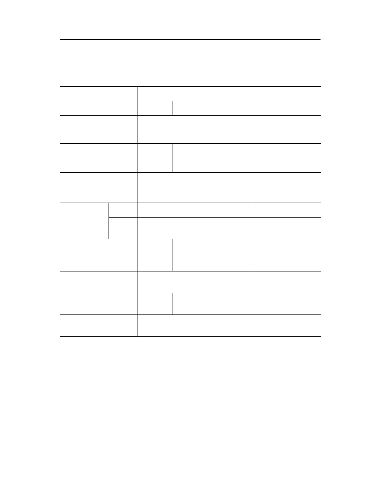
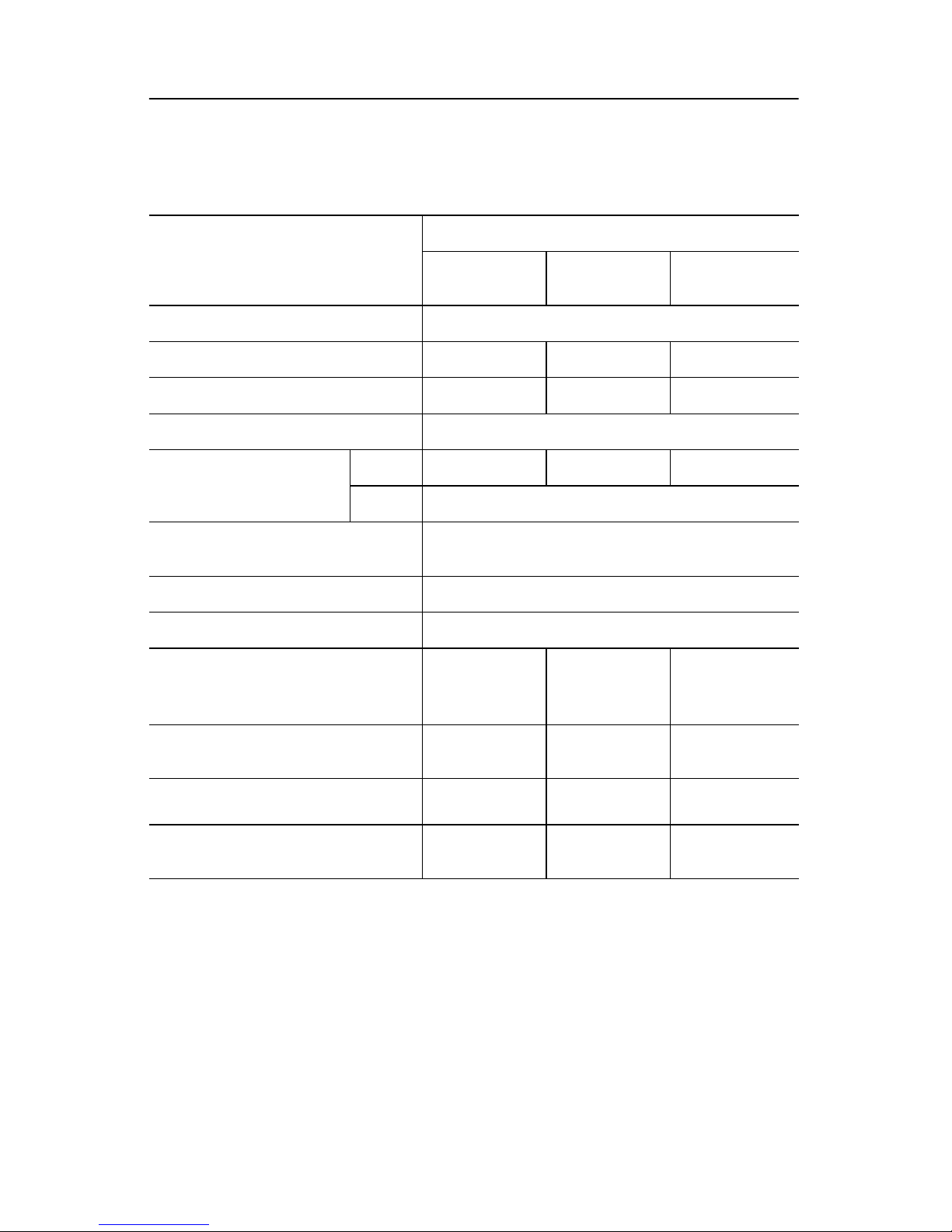
Table 7: Specifications for Input Modules 1746-IB8, -IB16, -ITB16, and -IC16
Catalog Number 1746-
Specification
IB8 IB16
Voltage Category 24V dc Signal Input (sinking)
Number of Inputs 816 16 16
Points per Common 816 16 16
Operating Voltage 10 to 30V dc (sinking)
(1)
ITB16
(1)
IC16
48V dc
Signal Input
(sinking)
30 to 60V dc at 55°C
30 to 55V dc at 60°C
(sinking)
(1)(2)
Backplane
5V dc 0.050A
Current
Consumptio
n
Signal Delay (max.)
Off State Voltage
(max.)
Off State Current
(max.)
Nominal Input
Current
(1)Removable Terminal Block.
(2)Use ID Code 0509 when configuring your system with programming software or the HHT.
(3)Typical signal delay for these modules: ON = 0.1 ms, OFF = 0.25 ms at 24V dc.
24V dc 0.0A
on = 8
ms
off = 8 ms
on = 8
ms
off = 8 ms
on = 0.3 ms
off = 0.5
(3)
ms
5.0V dc 10.0V dc
1 mA 1 mA 1.5 mA 1.5 mA
8 mA at 24V dc 4.1 mA at 48V dc
on = 4 ms
off = 4 ms
Publication 1746-IN005A-US-P
Page 13
Discrete I/O Modules 13
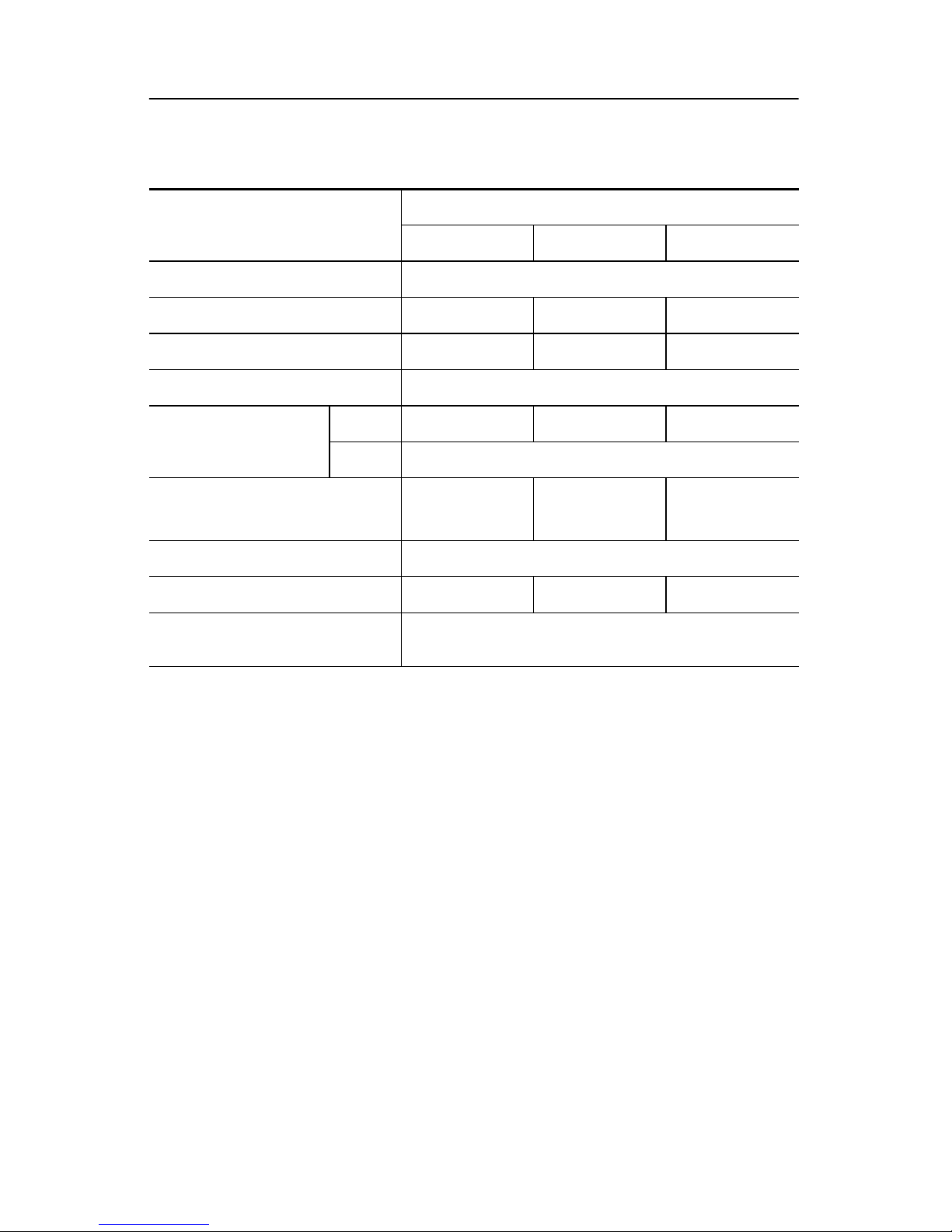
Table 8: Specifications for Input Modules 1746-IV8, -IV16, and -ITV16
Catalog Number 1746-
Specification
IV8 IV16
Voltage Category 24V dc Signal Input (sourcing)
Number of Inputs 81616
Points per Common 81616
Operating Voltage 10 to 30V dc (sourcing)
(1)
ITV16
(1)
Backplane Current
Consumption
Signal Delay (max.)
5V dc 0.050A 0.085A 0.085A
24V dc 0.0A
on = 8 ms
off = 8 ms
on = 8 ms
off = 8 ms
on = 0.3 ms
off = 0.5 ms
Off State Voltage (max.) 5.0V dc
Off State Current (max.) 1 mA 1 mA 1.5 mA
Nominal Input Current at
24V dc
(1)Removable Terminal Block.
(2)Typical signal delay for these modules: ON = 0.1 ms, OFF = 0.25 ms at 24V dc.
8 mA
(2)
Publication 1746-IN005A-US-P
Page 14
14 Dis cre te I/ O Mod ule s
Table 9: Specifications for Input Module 1746-IG16
Specification 1746-IG16
Voltage Category 5V dc TTL Signal Input (sourcing)
Number of Inputs 16
Points per Common 16
Operating Voltage
Backplane Current
Consumption
Signal Delay (max.)
Off State Voltage (max.)
Off State Current (max.) 4.1 mA
Nominal Input Current at 5V dc 3.7 mA
(1)Removable Terminal Block.
5V dc 0.140A
24V dc 0.0A
4.5 to 5.5V dc (sourcing)
50 mV peak to peak ripple (max.)
on = 0.25 ms
off = 0.50 ms
2.0V dc
(1)
(2)
(2)TTL inputs are inverted (-2.0 to +0.8V dc = low voltage = True = ON). Use a NOT
instruction in your ladder program to convert to traditional True = High logic.
ATTENTION: To avoid potential damage to TTL modules,
handle them by the ends of the module, not metallic surfaces.
Electrostatic discharges can damage the module. Care should be
!
taken to prevent exposure of terminals or components to
electrostatic charges.
Careful wire routing within the enclosure helps cut down electrical noise between
I/O lines. Refer to the SLC 500 Modular Hardware Style Installation and
Operation Manual, publication 1747-6.2, for recommended wiring pro cedures
for TTL modules.
Cable Length - Limit cable length to 15 meters (50 feet) per point for inputs in
standard enviro nments. R efer to Allen-Bradley Pr ogrammable Controller Wiring
and Grounding Guidelines, publication 1770-4.1, for complete information.
Publication 1746-IN005A-US-P
Page 15

Discrete I/O Modules 15
Table 10:Specifications for Input Module 1746-IN16
Specification 1746-IN16
(1)
Voltage Category 24V ac/dc Signal Input
Number of Inputs 16
Points per Common 16
dc 10 to 30V dc (sinking)
Operating Voltage
ac 10 to 30V ac
Backplane Current
Consumption
5V dc 0.085A
24V dc 0.0A
dc
on = 15 ms
off = 15 ms
Signal Delay (max.)
ac
on = 25 ms
off = 25 ms
dc 3.0V dc
Off State Voltage (max.)
ac 3.0V ac
dc 1 mA
Off State Current (max.)
ac 1 mA
dc 8 mA at 24V dc
Nominal Input Current
ac 8 mA at 24V ac
Inrush Current (max.) 0.02A (ac only)
(1)Removable Terminal Block.
Publication 1746-IN005A-US-P
Page 16
16 Dis cre te I/ O Mod ule s
Table 11:Specifications for Input Module 1746-IH16
Specification 1746-IH16
(1)(2)(3)
Voltage Category 125V dc Signal Input (sinking
Number of Inputs 16
Points per common 16
Range:
• 90 to 146V dc
Operating Voltage
Max. Points O N Simult aneo usly :
• 16 at 146V dc and 30°C
• 12 at 146V dc and 50°C
• 14 at 132V dc and 55°C
• 16 at 125V dc and 60°C
Backplane
5V dc 0.085A
Current
Consumption
Signal Delay (max.)
24V dc 0.0A
on = 9 ms
off = 9 ms
Off State Voltage (max.) 20 .0V dc
Off State Current (max.) 0.8mA
Nominal Input Current
2.15 mA at 125V dc
2.25 mA at 132V dc
(1)Removable Terminal Block.
(2)Use ID Code 0507 when configuring your system with programming software or the HHT.
(3)If the input module is connected in parallel with an inductive load, use surge suppression
across the load to protect the input module from damage caused by reverse voltage.
Refer to the
publication 1747-6.2, for more information on surge suppression.
SLC 500 Modular Hardware Style Installation and Operation Manual
,
Publication 1746-IN005A-US-P
Page 17
Discrete I/O Modules 17
Output Modules - ac
Table 12:Specifications for Output Modules 1746-OA8, -OA16, and -OAP12
Catalog Number 1746-
Specification
OA8 OA16
(1)
OAP12
(1)(2)(3)
(4)
Voltage Category 120/240V ac Signal Input
Number of Outputs 81612
Points per Common 486
Operating Voltage 85 to 265V ac at 47 to 63 Hz
Backplane Current
Consumption
Max. Signal Delay, Resistive
(5)
Load
Off State Leakage (max.)
5V dc 0.185A 0.370A 0.370A
24V dc 0.0A
on = 1 ms, off = 11.0 ms
(6)
2 mA
Load Current (min.) 10 mA
Continuous Current per
(7)
Point
1.0A at 30°C
0.50A at 60°C
0.50A at 30°C
0.25A at 60°C
2.0A at 30°C
1.25A at 55°C
1.0A at 60°C
Continuous Current
per Module (max.)
8.0A at 30°C
4.0A at 60°C
On State Voltage Drop (max.) 1.50V at 1.0A
Surge Current per Point
(8)
10.0A for 25 ms10.0A for 25
(max.)
(1)Removable Terminal Block.
(2)A fused common and blown fuse LED are provided on this module. See “Fuse Protection
and Blown Fuse Diagnostics” on page 32.
(3)Use ID Code 2803 when configuring your system with programming software or the HHT.
(4)Certified for Class 1, Division 2 hazardous location by CSA.
(5)Triac outputs turn on at any point in the ac line cycle, and turn off at ac line zero cross.
(6)To limit the effects of leakage current through solid state outputs, a loading resistor can
be connected in parallel with your load. For 120V ac operation, use a 15K
For 240V ac operation, use a
15K Ω, 5W resistor.
8.0A at 30°C
4.0A at 60°C
1.50V at
0.50A
ms
9.0A at 30°C
6.0A at 60°C
1.2V at 2.0A
17.0A for 25
(9)
ms
Ω,
2W resistor.
Publication 1746-IN005A-US-P
Page 18

18 Dis cre te I/ O Mod ule s
(7)Recommended surge suppression: For triac outputs when switching 120V ac inductive
loads, use Harris Metal-Oxide Varistor, model number V220MA2A. Refer to the
Modular Hardware Style Installation and Operation Manual
more information on surge suppression.
(8)Repeatability is once every 1s at 30°C. Repeatability is once every 2s at 60°C.
(9)Surge current = 35A per common for 10 ms.
, publication 1747-6.2, for
SLC 500
Publication 1746-IN005A-US-P
Page 19

Discrete I/O Modules 19
Output Modules - dc
Table 13:Specifications for Output Modules 1746-OB8, -OB16, and -OB16E
Catalog Number 1746-
Specification
OB8 OB16
Number of Outputs 81616
Points per Common 81616
Voltage Category 24V dc Signal Output
(1)
OB16E
(1)(2)
Operating Voltage (V dc) 10 to 50 (source)
Backplane Current
Consumption
Signal Delay (max.).
Resistive Load.
Off State Leakage (max.)
5V dc 0.135A 0.280A 0.135A
24V dc 0.0A
on = 0.1 ms
off = 1.0 ms
(4)
on = 0.1 ms
off = 1.0 ms
1 mA
10 to 30
(source)
on = 1.0 ms
off = 1.0 ms
(3)
Load Current (min.) 1 mA
Continuous Current per
(5)
Point
Continuous Current per
Module
1.0A at 30°C
0.50A at 60°C
8.0A at 30°C
4.0A at 60°C
0.50A at 30°C
0.25A at 60°C
8.0A at 30°C
4.0A at 60°C
1.0A at 30°C
0.50A at 60°C
8.0A at
0 to 60°C
On State Voltage Drop (max.) 1.2V at 1.0A 1.2V at 0.50A 1.0V at 0.50A
Surge Current per Point
(7)
3.0A for 10 ms 3.0A for 10 ms
2.0A for 10
(8)
ms
(6)
(1)Removable Terminal Block.
(2)Use the following ID Code when configuring your system with programming software or
the HHT: 1746-OB16E = 2920.
(3)Fa st turn-off modules (1746-OB6EI, -OBP8 Series B and later, -OB16E Series B and
later, -OBP16, and
-OVP16) provide fast OFF delay for inductive loads. Comparative OFF delay times for
1746-OB8/-OV8 and fast turn-off modules, when switching Bulletin 100-B110 (24W
sealed) contactor, are: 1746-OB8/-OV8 OFF delay = 152 ms; fast turn-off modules OFF
delay = 47 ms.
(4)To limit the effects of leakage current through solid state outputs, a loading resistor can
be connected in parallel with your load. For transistor outputs, 24V dc operation, use a
5K Ω, 1/2W resistor.
Publication 1746-IN005A-US-P
Page 20

20 Dis cre te I/ O Mod ule s
(5)Recommended surge suppression: For transistor outputs when switching 24V dc
inductive loads, use a 1N4004 diode reverse-wired across the load. Refer to the
Modular Hardware Style Installation and Operation Manual
more information on surge suppression.
(6)Fa st off delay for inductive loads is accomplished with surge suppressors on the 1746-
OB6EI, -OBP8 Series B and later, -OB16E Series B and later, -OBP16, and -OVP16
modules. A suppressor at the load is not needed unless another contact is connected in
series. If this is the case, a 1N4004 diode should be reverse wired across the load. This
defeats the fast turn-off feature.
(7)Repeatability is once every 1s at 30°C. Repeatability is once every 2s at 60°C.
(8)Surge current = 32A per module for 10 ms.
, publication 1747-6.2, for
SLC 500
ATTENTION: A transient pulse occurs in transistor outputs
when the external dc supply voltage is applied to the output
common terminals (e.g., via the master control relay). This can
!
occur regardless of the processor having power or not. For most
applications, the energy of this pulse is not sufficient to energize
the load. Refer to the SLC 500 Modular Hardware Style
Installation and Operation Manual, publication 1747-6.2, for
more information on transien t pul s es and gui deli nes to reduce
inadvertent processor operation.
Publication 1746-IN005A-US-P
Page 21

Discrete I/O Modules 21
T ab le 14:Specificatio ns for Outp ut Module s 1746-OB 6EI, -OBP8, an d -OBP16
Catalog Number 1746-
Specification
OB6EI
(1)(2)
OBP8
(1)(2)(3)
OBP16
(1)(2)(4)
(5)
Number of Outputs 6816
Points per Common
Individually
Isolated
416
Voltage Category 24V dc Signal Output
Operating Voltage (V dc)
Backplane Current
Consumption
5V dc 0.046A 0.135A 0.250A
24V dc 0.0A
Signal Delay (max.).
Resistive Load.
Off State Leakage (max.)
(7)
10 to 30
(source)
on = 1.0 ms
off = 2.0 ms
(6)
20.4 to 26.4 (source)
on = 1.0 ms
(6)
off = 2.0 ms
1 mA
on = 0.1 ms
off = 1.0 ms
(6)
Load Current (min.) 1 mA
Continuous Current per
(8)(9)
Point
2.0A at 0 to
60°C
2.0A at 0 to
60°C
1.5A at 30°C
1.0A at 60°C
Continuous Current per
Module
On State Voltage Drop
(max.)
Surge Current per Point
Surge Current per
Module
(10)
12.0A at 0 to
1.0V at 2.0A 1.0V at 2.0A 1.0V at 1.0A
(10)
4.0A for 10 ms 4.0A for 10 ms 4.0A for 10 ms
24.0A for 10 ms
60°C
8.0A at 0 to
60°C
32.0A for 10 ms32.0A for 10
6.4A at
0 to 60°C
ms
Electronic Protection yes no no
(1)Removable Terminal Block.
(2)Use the following ID Code when configuring your system with programming software or
the HHT: 1746-OB6EI = 2619, 1746-OBP8 = 2721 and 1746-OBP12 = 2921.
(3)An external fuse can be used to protect this module from short circuits. Recommended
fuse is SANO MQ4-3.15A, 5x20 mm.
(4)A fused common and blown fuse LED are provided on this module. See “Fuse Protection
and Blown Fuse Diagnostics” on page 32.
(5)Certified for Class 1, Division 2 hazardous location by CSA.
Publication 1746-IN005A-US-P
Page 22

22 Dis cre te I/ O Mod ule s
(6)Fa st turn-off modules (1746-OB6EI, -OBP8 Series B and later, -OB16E Series B and
later, -OBP16, and
-OVP16) provide fast OFF delay for inductive loads. Comparative OFF delay times for
1746-OB8/-OV8 and fast turn-off modules; when switching Bulletin 100-B110 (24W
sealed) contactor, are: 1746-OB8/-OV8 OFF delay = 152 ms; fast turn-off modules OFF
delay = 47 ms.
(7)To limit the effects of leakage current through solid state outputs, a loading resistor can
be connected in parallel with your load. For transistor outputs, 24V dc operation, use a
5.6K Ω, 1/2W resistor.
(8)Recommended surge suppression: For transistor outputs when switching 24V dc
inductive loads, use a 1N4004 diode reverse-wired across the load (also see footnote 9).
Refer to the
publication 1747-6.2, for more information on surge suppression.
(9)Fa st off delay for inductive loads is accomplished with surge suppressors on the 1746-
OB6EI, -OBP8 Series B and later, -OB16E Series B and later, -OBP16, and -OVP16
modules. A suppressor at the load is not needed unless another contact is connected in
series. If this is the case, a 1N4004 diode should be reverse wired across the load. This
defeats the fast turn-off feature.
(10)Repeatability is once every 1s at 30°C. Repeatability is once every 2s at 60°C.
SLC 500 Modular Hardware Style Installation and Operation Manual
,
!
ATTENTION: A transient pulse occurs in transistor outputs
when the external dc supply voltage is applied to the output
common terminals (e.g., via the master control relay). This can
occur regardless of the processor having power or not. For most
applications, the energy of this pulse is not sufficient to energize
the load. Refer to the SLC 500 Modular Hardware Style
Installation and Operation Manual, publication 1747-6.2, for
more information on transien t pul s es and gui deli nes to reduce
inadvertent processor operation.
Publication 1746-IN005A-US-P
Page 23

Discrete I/O Modules 23
Table 15:Specifications for Output Modules 1746-OV8, -OV16, and -OVP16
Catalog Number 1746-
Specification
OV8 OV16
(1)
OVP16
(1)(2)(3)
(4)
Number of Outputs 81616
Points per Common 81616
Voltage Category 24V dc Signal Output
Operating Voltage (V dc) 10 to 50 (sink)
Backplane
5V dc 0.135A 0.270A 0.250A
20.4 to 26.4
(sink)
Current
Consumption
Signal Delay (max.). Resistive
Load.
Off State Leakage (max.)
24V dc 0.0A
on = 0.1 ms
off = 1.0 ms
(6)
1 mA
on = 0.1 ms
off = 1.0 ms
(5)
Load Current (min.) 1 mA
0.50A at
30°C
0.25A at
60°C
1.5A at 30°C
1.0A at 60°C
(8)
Continuous Current per Point
1.0A at 30°C
(7)
0.50A at
60°C
Continuous Current per Module
8.0A at 30°C
4.0A at 60°C
6.4A at
0 to 60°C
On State Voltage Drop (max.) 1.2V at 1.0A 1.2V at 0.5A 1.0V at 1.0A
Surge Current per Point
(1)Removable Terminal Block.
(2)A fused common and blown fuse LED are provided on this module. See “Fuse Protection
and Blown Fuse Diagnostics” on page 32.
(3)Use the following ID Code when configuring your system with programming software or
the HHT: 1746-OVP16 = 2922.
(4)Certified for Class 1, Division 2 hazardous location by CSA.
(5)Fa st turn-off modules (1746-OB6EI, -OBP8 Series B and later, -OB16E Series B and
later, -OBP16, and -OVP16) provide fast OFF delay for inductive loads. Comparative
OFF delay times for 1746-OB8/-OV8 and fast turn-off modules; when switching Bulletin
100-B110 (24Ws sealed) contactor, are: 1746-OB8/-OV8 OFF delay = 152 ms; fast turn-
off modules OFF delay = 47 ms.
(9)
3.0A for 10 ms
4.0A for 10
(10)
ms
Publication 1746-IN005A-US-P
Page 24

24 Dis cre te I/ O Mod ule s
(6)To limit the effects of leakage current through solid state outputs, a loading resistor can
be connected in parallel with your load. For transistor outputs, 24V dc operation, use a
5.6K Ω, 1/2W resistor.
(7)Recommended surge suppression: For transistor outputs when switching 24V dc
inductive loads, use a 1N4004 diode reverse-wired across the load (also see footnote 9).
Refer to the
publication 1747-6.2, for more information on surge suppression.
(8)Fa st off delay for inductive loads is accomplished with surge suppressors on the 1746-
OB6EI, -OBP8 Series B and later, -OB16E Series B and later, -OBP16, and -OVP16
modules. A suppressor at the load is not needed unless another contact is connected in
series. If this is the case, a 1N4004 diode should be reverse wired across the load. This
defeats the fast turn-off feature.
(9)Repeatability is once every 1s at 30°C. Repeatability is once every 2s at 60°C.
(10)Surge current = 32A per module for 10 ms.
SLC 500 Modular Hardware Style Installation and Operation Manual
,
ATTENTION: A transient pulse occurs in transistor outputs
when the external dc supply voltage is applied to the output
common terminals (e.g., via the master control relay). This can
!
occur regardless of the processor having power or not. For most
applications, the energy of this pulse is not sufficient to energize
the load. Refer to the SLC 500 Modular Hardware Style
Installation and Operation Manual, publication 1747-6.2, for
more information on transien t pul s es and gui deli nes to reduce
inadvertent processor operation.
Publication 1746-IN005A-US-P
Page 25

Discrete I/O Modules 25
Table 16:Specifications for Output Module 1746-OG16
Specification 1746-OG16
Number of Outputs 16
Points per Common 16
Voltage Category 5V dc TTL Signal Input (sinking)
Operating Voltage
Backplane Current
Consumption
Signal Delay (max.). Resistive
Load.
Off State Leakage (max.) 0.1 mA
Load Current (min.) 0.15 mA
Continuous Current per Point 24 mA
(1)Removable Terminal Block.
5V dc 0.180A
24V dc 0.0A
50mV peak to peak ripple (max.)
4.5 to 5.5V dc
on = 0.25 mA
off = 0.50 mA
(1)
(2)
(2)TTL outputs are inverted (0 to 0.4V dc = low voltage = True = ON). Use a NOT instruction
in your ladder program to convert to traditional True = High logic.
ATTENTION: To avoid potential damage to TTL modules,
handle them by the ends of the module, not metallic surfaces.
Electrostatic discharges can damage the module. Care should be
!
taken to prevent exposure of terminals or components to
electrostatic charges.
Careful wire routing within the enclosure helps cut down electrical noise between
I/O lines. Refer to the SLC 500 Modular Hardware Style Installation and
Operation Manual, publication 1747-6.2, for recommended wiring pro cedures
for TTL modules.
Cable Length - Limit cable length to 3 meters (10 feet) per point for ou tputs in
standard enviro nments. R efer to Al len-B radley Programmabl e Controller Wiring
and Grounding Guidelines, publication 1770-4.1, for complete information.
Publication 1746-IN005A-US-P
Page 26

26 Dis cre te I/ O Mod ule s
Relay Contact Output Modules
Table 17:Specifications for Output Modules 1746-OW4, -OW8, -OW16, and OX8
Catalog Number 1746-
Specification
Number of Outputs 48168
OW4
(1)
OW8
(1)
OW16
(1)(2)
OX8
(1)(2)
Points per Common 448
Individually
Isolated
Voltage Category ac/dc Relay
5V dc 5 to 125
Operating
Voltage
Backplane
Current
Consumption
Signal Delay (max.) .
Resistive Load.
Off State Leakage
(max.)
24V
ac
5 to 265
5V dc 0.045A 0.085A 0.170A 0.085A
24V
dc
0.045A 0.090A 0.180A 0.090A
on = 10.0 ms
off = 10.0 ms
0 mA
Load Current (min.) 10mA at 5V dc
Continuous Current
per Point
(3)
See relay contact ratings. (Table 18 and Table 19 on
page 27)
Continuous Current
per Module
(1)Certified for Class 1, Division 2 hazardous location by CSA.
(2)Removable Terminal Block.
(3)Recommended surge suppression: For relay contact outputs, refer to the
Installation and Operation Manual
across your external inductive load will extend the life of SLC 500 relay contacts.
(4)The continuous current per module must be limited so the module power does not
exceed 1440 VA.
Publication 1746-IN005A-US-P
8.0A ac
8.0A /
Common
, publication 1747-6.2. Connecting surge suppressors
16.0A ac
8.0A /
Common
16.0A ac
8.0A /
Common
(4)
SLC 500
Page 27

Discrete I/O Modules 27
Relay Contact Rati ngs
Table 18:Relay Contact Rating Table for Output Modules 1746-OW4, -OW8,
and -OW16
Voltages:
Amperes
Make Break Make Break
(1)
Amperes
Continuous
(2)
V olt-Amperes
120 15 1.5
Maximum Volt s (ac )
2.5 1800 180
240 7.5 0.75
Maximum Volts
(dc)
125
24
0.22
1.2
(3)
(3)
1.0 28
2.0 28
Table 19:Relay Contact Rating Table for Output Module 1746-OX8
(3)
(3)
(1)
Amperes
Continuous
(2)
Volt-Amperes
5.0 3600 360
1.0 28
2.0 28
Voltages:
Maximum Volts
(ac)
Maximum Volts
(dc)
Amperes
Make Break Make Break
120 30 3.0
240 15 1.5
125
24
0.22
1.2
(1)Recommended surge suppression: For relay contact outputs, refer to the
Installation and Operation Manual
across your external inductive load will extend the life of SLC 500 relay contacts.
(2)The continuous current per module must be limited so the module power does not
exceed 1440 VA.
(3)For dc voltage applications, the make/break ampere rating for relay contacts can be
determined by dividing 28 VA by the applied dc voltage. For example, 28 VA/48V dc =
0.58A. For dc voltage applications less than 14V, the make/break ratings for relay
contacts cannot exceed 2A.
, publication 1747-6.2. Connecting surge suppresors
SLC 500
Publication 1746-IN005A-US-P
Page 28

28 Dis cre te I/ O Mod ule s
Input/Output Combination Modules
Table 20:Specifications for Combination Modules 1746-IO4, -IO8, -IO12, and
-IO12DC
Catalog Numbe r 1746-
Specification
IO4
(1)(2)
IO8
(1)(2)
IO12
(1)(3)
(4)
IO12DC
(7)
(3)(5)(6)
Points per Module
2 inputs
2 outputs
4 inputs
4 outputs
6 inputs
6 outputs
6 inputs
6 outputs
Points per Common 246 6
Voltage Category
(Inputs)
Operating Voltage
(Inputs)
Voltage Category
(Outputs)
Operating Voltage
(Outputs)
Backplane
5V dc 0.030A 0.060A 0.090A 0.080
120V ac 24V dc
85 to 132V ac 10 to 30V dc
100/120V ac Relay contact output
5 to 265V ac
5 to 125V dc
Current
Consumption
(1)Certified for Class 1, Division 2 hazardous location by CSA.
(2)See specifications for catalog numbers 1746-IA4 and 1746-OW4. Continuous Current per
1746-IO4 Module is 4.0A. Continuous Current per 1746-IO8 Module is 8.0A.
(3)Removable Terminal Block.
24V dc 0.025A 0.045A 0.070A 0.060
(4)See specifications for catalog numbers 1746-IA16 and 1746-OW16. Continuous Current
per 1746-IO12 Module is 8.0A.
(5)See specification for catalog numbers 1746-IB16 and 1746-OW16. Continuous Current
per 1746-IO12DC Module is 8.0A.
(6)Certified for Class 1, Division 2 hazardous location by C-UL.
(7)Use the following ID Code when configuring your system with programming software or
the HHT: 1746-IO12DC = 1512.
Publication 1746-IN005A-US-P
Page 29

Discrete I/O Modules 29
Note:
Combination I/O modules (Catalog Numbers 1746-IO4, 1746-IO8, 1746-IO12 and
1746-IO12DC:
For the first sev era l se conds of any powerup or when power is applied to a rack that is
not under processo r cont rol , the output LEDs of the combination IO modules in the ra ck
will be illuminated.
Racks are not und er processor control if on e of t he following conditi ons exist:
Modular Hardware Style (only):
Processor is absent from the rack or the rack interconnect cable is not properly
connected.
Modular Hardware Style and Fixed Hardware Style:
The processor does not have the firmware PROM installed or the pro cessor is not
functioning properly.
Publication 1746-IN005A-US-P
Page 30

30 Dis cre te I/ O Mod ule s
Octal Label Kit Installation (for PLC Processors Only)
The octal label kit consists of an octal filter label and a door label. Use these octal
labels to replace the decimal labels that are attached to the I/O modules. The octal
label kit is included with the I/O modules and can also be obtained through your
Allen-Bradley distributor.
ATTENTION: Do not touch or remo ve th e terminal block when
the SLC 500 system is powered. Contact with ac line potential
!
Applying the Octal Filter Label
1. Remove the octal filter label from its paper carrier.
2. Align the octal filter label numbers horizontally to the module color bar and
over the decimal filter numbers.
may cause injury to pe rs onnel.
3. Apply the octal label to the filter.
4. Press firmly to ensure proper adhesion of the label.
Applying the Octal Door Label
1. Remove the octal door lab e l from its paper carrier.
2. Align the octal label directly over the decimal door label on the inside of the
door .
3. Press firmly to ensure proper adhesion of the label.
Publication 1746-IN005A-US-P
Page 31

Discrete I/O Modules 31
Removable Terminal Blocks
Colored terminal blocks are removable by loosening the upper and lower
retaining screws. Black terminal blocks are not removable.
Figure 1:Installing Octal Labels
Module Color Bar
Beveled Edge
Removable
Terminal
Block
Termi nal Wiring
max. #14 AWG (2mm
max. 2 wires per terminal
max. torque: 0.9Nm (8 in-lbs)
2
)
Octal Filter Label
Upper Retaining Screw Maximum
Torque = 0.6 Nm (5.3 in-lbs)
1746-XXXX 1746-XXXX(OCTAL)
Octal Door Label
Lower Retaining Screw Maximum
Torque = 0.6 Nm (5.3 in-lbs)
OCTAL
Publication 1746-IN005A-US-P
Page 32

32 Dis cre te I/ O Mod ule s
Fuse Protection and Blown Fuse Diagnostics
This section describes fusing characteristics for the following modules:
• Catalog 1746-OBP16
• Catalog 1746-OVP16
• Catalog 1746-OAP12
Fuse Protection (1746-OBP16 and 1746-OVP16)
The fuse on the 1746-OBP1 6 and 1746 -OVP16 mod ules (s hown on pag e 33) has
been desig ned to provide short-circuit protection for wiring only (16 AWG or
larger) to external loads. In the event of a short circuit on an output channel, it is
likely that the transistor associated with that channel will be damaged and the
module should be replaced or a spare output channel used for the load. The fuse
does not provide overload protection. In the event of an overload on an output
channel, it is likely that the fuse will not blo w and the transistor associated with
that channel will be damaged. To provide overload protection for your
application, user-supplied fuses should be installed externally and pro perly sized
to match your individual load characteristics.
Fuse Protection (1746-OAP12)
A fuse is provided on each common of the 1746-OAP12 module (shown on
page 34) for a total of 2 fuses. The fuses are designed to protect the mod ule fro m
short-circuit conditions. The fuse do e s not provide overload protectio n. In the
event of an overload on an output channel, it is likely that the fuse will not blow
and the output device associated with that channel will be damaged. To provide
overload pro t ection for yo ur applicatio n, user-supplied fuses should be installed
externally. Recommended fuse for overload protection is SAN-O HT. Select the
fuse rating according to your load. Do not use HT fuses rated higher than 2.0A.
Blown Fuse Diagnostics
If the fuse blows on the 1746-OBP16, -OVP16 or -OAP12, the following occurs:
1. The blown fuse LED will illuminate provided power (5V dc via backplane
and load power via external supply) is applied to the module.
2. A processor error will occur if JP1 connects pins 2 and 3. (See figures on
page 33 and page 34.)
Publication 1746-IN005A-US-P
Page 33

Discrete I/O Modules 33
Figure 2:Location of Jumpers and Fuses for 1746-OBP16 and -OVP16
Location for 1746-OBP16 Fuse (F1)
JP 1
3
2
1
OUTPUT
Jumper for processor
notification (JP1)
Location for 1746-OVP16 Fuse (F1)
F
U
S
E
Blown Fuse LED
Left Side View
WHEN FUSE OPENS
JP1
23
REPLACEMENT FUSE:
LITTELFUS E 322010
A-B CAT. NO. 1746-F8
Jumper Settings and
Fuse Replacement
Information
12
PROCESSOR
CONTINUES
PROCESSOR
FAULTS
Front View
Publication 1746-IN005A-US-P
Page 34

34 Dis cre te I/ O Mod ule s
Figure 3:Location of Jumpers and Fuses for 1746-OAP12
F1
23
1
JP1
Left Side View
Jumper for processor
notification (JP1)
OUTPUT
Front View
F2
WHEN FUSE OPENS
1
2
F
U
S
E
Blown Fuse LED
JP1
23
PROCESSOR
CONTINUES
PROCESSOR
FAULTS
REPLACEMENT FUSE:
SAN-O HQ 6.3A
A-B CAT. NO. 1746-F9
Jumper Settings and
Fuse Replacement
Information
Publication 1746-IN005A-US-P
Page 35

Discrete I/O Modules 35
Processor Operation in Case of Blown Fuse - Processor
Continues
The factory set position for JP1 is shown in Figure 4. For this JP1 configuration,
the processor operation will continue if the module fuse blow s.
Figure 4:JP1 Factory Set Position (No Processor Notification)
JP1
3
2
1
1746-OBP16 and -OVP16
2
3
1746-OAP12
1
JP1
JP1 is in Factory Set position.
There is no processor notification
for blown fuse.
Processor Operation in Case of Blown Fuse - Processor
Faults
The Processor Fault pos i tio n for JP 1 is sh own i n Figure 5 on t he foll o win g page.
For this JP1 confi guration, the processor ge nerates a non- recoverable erro r for all
SLC 500 processors. For a non-recoverable error, note the following:
• Processor operation halts and the processor fault light flashes.
• All outputs are reset to OFF.
• The processor major fault bi t S:1/13 is set.
• Monitor processor status file word S:6 for er ror code x x58 for SLC 500 and
5/01™ processors, and error code xx60 for SLC 5/02™ and higher
processors.
Publication 1746-IN005A-US-P
Page 36

36 Dis cre te I/ O Mod ule s
s
Figure 5:JP1 in Processor Fault Notification Position
JP1
3
2
1
1746-OBP16 and -
1
2
3
JP1 is in processor Fault Position
Processor is notified when fuse i
blown.
1746-
JP1
IMPORTANT: When using SLC 5/02 and higher processors, a User Fault Routine
cannot be used to clear the major fault bit.
ATTENTION: For 1746-OBP16/-OVP16, all outputs on the
module are OFF if the fuse blows. For 1746-OAP12, all outputs
on the same common as the blown fuse are OFF. If processor
!
operation is allowed to continue after a blown fuse, extreme care
should be taken to ensure the safety of personnel and guard
against equipment damage.
For additional information on processor fault codes and user fault routines refer
to the following user manuals:
• Your pro gramm ing device’s reference manual
• HHT User Manual, publication 1747-NP002:
Chapter 28, Troubleshooting Faults
Chapter 29, Understanding the Fault Routine
Table 21 defines operation of all SLC 500 processors in the case of a blown fuse
in a 1746-OBP16, -OVP16 and -OAP12:
T able 21:Processor Operation After A Bl own Fuse (174 6-OBP16, -OVP16 an d
-OAP12)
JP1 Set to
Processor Continues
Publication 1746-IN005A-US-P
JP1 Set to
Processor Faults
Page 37

Discrete I/O Modules 37
No error. Processor continues with 1746OBP16/-OVP16 outputs de-energized. 1746OAP12 outputs, on the same common as the
blown fuse, are de-energized.
Non-recoverable error.
Processor operat ions stops and
all outputs reset to OFF.
Publication 1746-IN005A-US-P
Page 38

38 Dis cre te I/ O Mod ule s
Recovery From Blown Fuse/Processor Fault/Processor
Shutdown
Processor operation will stop under the following conditions:
• The output module fuse blows due to a short circuit.
• JP1 is set to the Processor Faults position (pins 2 and 3 connected).
If the above conditions occur, the following procedures should be used for
recovery:
1. Follow fuse replacement procedures shown on page 39.
2. Clear the processor major fault bit S:1/13.
3. Clear processor status file S:6 major error code (optional).
4. Return processor to Run Mode.
For additional information on processor fault codes and clearing processor fault
bits, refer to the following user manuals:
• Your pro gramm ing device’s reference manual
• HHT User Manual, publication 1747-NP002
Chapter 28, Troubleshooting Fault
Chapter 29, Understanding the Fault Routine
Replacement Fuse Recommendations
Use the following replacement fuses -
• 1746-OBP16/-OVP16 -Littelfuse #32201 0,10A. This fuse is required to
maintain UL/CSA rating. Replacement Fuse Kit is catalog number
1746-F8. (5 fuses per kit).
• 1746-OAP12 -Use SAN-O HQ 6.3A for replacement. This fuse is required
to maintain UL/CSA rating. Replacement Fuse Kit is catalog number
1746-F9 (5 fuses per kit).
Publication 1746-IN005A-US-P
Page 39

Discrete I/O Modules 39
Fuse Replacement Procedure
To replace a blown fuse:
ATTENTION: Never install, remove, or wire modules with
power applied to chassis.
!
1. Remove SLC 500 system power and correct the conditions causing the
short circuit.
2. Remove the output module from the chassis.
3. Remove the fuse.
• 1746-OBP16/-OVP16: Use a wide tipped, slotted head screw driver to
remove the blown fuse. Slide the screw driver tip under the fuse and use
a twisting motion to pry the fuse from the fuse clip. Use care so that the
printed circuit board and surrounding electronics are not damaged.
• 1746-OAP12: A fuse holder is provided with each fuse. Simply g rasp the
fuse holder with needle-nose pliers, or your fingers, and pull it out.
4. Replace the fuse.
• 1746-OBP16/OVP 16: Center th e
press down. If a tool is used to press the fuse in place, apply pressure to
the metal end caps only, not the center of the fuse.
• 1746-OAP12: Inser t a new fuse into the fuse holde r , ali gn fuse hold er on
fuse clips and press down.
5. Replace the output module in the chassis.
6. Restore SLC 500 system power. Clear processor fault bits as indicated in
the steps provided on page 38.
replacement fuse over the fuse clip an d
Publication 1746-IN005A-US-P
Page 40

40 Dis cre te I/ O Mod ule s
Electronically Protected Modules (1746-OB6EI and OB16E)
Electronic Protection
The electronic protection of the 1746-OB6EI and -OB16E has been designed to
provide protection for the modules from short circuit and overload current
conditions. The protection is based on a thermal cut-out principle. In the event of
a short circuit or overload current con dition on an output channel , that channel
will limit current within milliseconds after it s thermal cut-out temperature has
been reached. All other channels continue to operate as directed by the CPU
(processor) mo dule.
IMPORT ANT : The modules do not provide protection against reverse polarity
wiring or wiring to AC power sources . Electroni c protect ion is not
intended to replace fuses, circuit breakers, or other code-required
wiring protection devices.
Front View
OUTPUT
OUTPUT
E
E
F
F
U
U
S
S
E
E
EFUSE LED
Note: There is no jumper
setting on this module
Publication 1746-IN005A-US-P
Page 41

Discrete I/O Modules 41
Auto Reset Operation
IMPORTANT : The 1746-OB6EI and -OB16E perform auto-reset under overload
conditions. When an output channel overload occurs as described
on page 40, that channel will limit current within milliseconds
after its thermal cut-out temperature has been reached. While in
current limit, the output channel can cool below the thermal cutout temperature allowing the module to auto-reset and resume
control of the output channel as directed by the processor until the
thermal cut-out temperature is again reached.
Removing power from an overloaded output channel would also
allow the output channel to cool below the thermal cut-out
temperature, allowing auto-reset to occur when power is restored.
The output channel would operate as directed by the processor
until the thermal cut-out temperature is again reached.
To avoid auto-reset of an output channel under overload
conditions, an external mechanical fuse can be used to open the
circuit when overloaded.
Short Circuit/Overload Current Diagnostics
If a short circuit or overload current condition occurs on an output channel:
1. The E-Fuse LED will illuminate provided that power is applied to the
module. Power required: 5V dc via backplane and load power via an
external supply.
2. All other channels continue to operate as directed by the CPU (processor)
module.
Recovery From Channel Shutdown
1. Remove the SLC 500 system power and correct the conditions causing the
short circuit or overload current condition.
2. Restore the SLC 500 system power. The module automatically resets and
resumes control of the output channel and associated load.
Publication 1746-IN005A-US-P
Page 42

42 Dis cre te I/ O Mod ule s
Wiring Diagrams
The wiring diagrams in these installation instructions are examples only. It is not
necessary to connect an I/O device to each and every I/O module terminal.
Labeling for SLC/PLC® Systems
In this document, 16- point I/O module wi ring diagrams includ e both decimal and
octal numbers for I/O addressing and wire identification (see figure below). To
wire your 16-point I/O module when used in a SLC system, use the decimal
numbers in the upper left portion of each box. When used in a PLC system, use
the octal numbers in the lower right portion of the box. As shipped from the
factory, the I/O module has a decimal address label on the inside of its door. An
octal label kit should be included with your 16-point I/O modules, or a separate
octal conversion kit can be ordered, to allow you to convert your module to the
octal system.
IMPORTANT : Ensure the octal labels are used with your PLC system. Directions
on how to install the labels are included with the kit and on
page 30 of this document.
Figure 6:Decimal and Octal Labeling for 16-Point I/O Modules
1746-IA16
L1
For SLC (decimal)
IN 14
100/120V ac
16
For PLC (octal)
L2
100/120V ac
IN 0
IN 2
IN 4
IN 6
IN 8
IN 10
IN 14
AC COM
COMMONS
CONNECTED
INTERNALLY
IN 12
0
2
4
6
10
12
14
16
IN 1
IN 3
IN 5
5
IN 7
IN 9
11
IN 11
13
IN 13
15
IN 15
17
AC COM
1
3
7
SLC
PLC
Publication 1746-IN005A-US-P
Page 43

Discrete I/O Modules 43
Input Modules - ac
Figure 7:Wiring Diagrams (1746-IA4, -IA8, -IA16)
L1
100/120V ac
L2
1746-IA4
100/120V ac
NOT
USED
NOT
USED
NOT
USED
NOT
USED
IN 0
IN 1
IN 2
IN 3
AC COM
1746-IA16
100/120V ac
L1
100/120V ac
L2
1746-IA8
100/120V ac
COMMONS
CONNECTED
INTERNALLY
IN 0
IN 1
IN 2
IN 3
IN 4
IN 5
IN 6
IN 7
AC COM
AC COM
L1
100/120V ac
L2
IN 0
IN 2
IN 4
IN 6
IN 8
IN 10
IN 12
IN 14
AC COM
COMMONS
CONNECTED
INTERNALLY
0
2
4
6
10
12
14
16
IN 1
1
IN 3
3
IN 5
5
IN 7
7
IN 9
11
IN 11
13
IN 13
15
IN 15
17
AC COM
SLC
PLC
Publication 1746-IN005A-US-P
Page 44

44 Dis cre te I/ O Mod ule s
Figure 8:Wiring Diagrams (1746-IM4, -IM8, -IM16)
L1
200/240V ac
L2
1746IM4
200/240V ac
NOT
USED
NOT
USED
NOT
USED
NOT
USED
IN 0
IN 1
IN 2
IN 3
AC COM
1746-IM16
200/240V ac
L1
200/240V ac
L2
1746-IM8
200/240V ac
COMMONS
CONNECTED
INTERNALLY
IN 0
IN 1
IN 2
IN 3
IN 4
IN 5
IN 6
IN 7
AC COM
AC COM
L1
200/240V ac
L2
IN 0
IN 2
IN 4
IN 6
IN 8
IN 10
IN 12
IN 14
AC COM
COMMONS
CONNECTED
INTERNALLY
10
12
14
16
0
2
4
6
IN 1
IN 3
IN 5
IN 7
IN 9
11
IN 11
13
IN 13
15
IN 15
17
AC COM
1
3
5
7
SLC
PLC
Publication 1746-IN005A-US-P
Page 45

Input Modules - dc
Figure 9:Wiring Diagram (1746-IN16)
1746-IN1 6
24V ac/dc SINKING
L1 or +DC
IN 0
IN 1
0
10
12
14
16
2
4
6
IN 3
IN 5
IN 7
IN 9
IN 11
IN 13
IN 15
AC/DC
COM
1
3
5
7
11
13
15
17
V ac/dc
L2 or -DC
IN 2
IN 4
IN 6
IN 8
IN 10
IN 12
IN 14
AC/DC
COM
COMMONS
CONNECTED
INTERNALLY
Discrete I/O Modules 45
SLC
PLC
Figure 10:Wiring Diagram (1746-IB8, -IB16, -ITB16, -IC16, -IH16)
+DC
24V dc
±DC
1746-IB8
24V dc SINKING
COMMONS
CONNECTED
IN 0
IN 1
IN 2
IN 3
IN 4
IN 5
IN 6
IN 7
DC COM
DC COM
1746-IB16, -ITB 16
24V dc SINKING
+DC
24V dc
(IB16, ITB16)
48V dc
(IC16)
125V dc
(IH16)
±DC
COMMONS
CONNECTED
1746-IC16
48V dc SINKING
IN 0
IN 1
0
2
4
6
6
10
12
14
16
DC COM
IN 3
IN 5
IN 7
IN 9
IN 11
IN 13
IN 15
11
13
15
17
1
3
5
7
IN 2
IN 4
IN 6
IN 8
IN 10
IN 12
IN 14
DC
COM
125V dc SINKING
1746-IH16
SLC
PLC
Publication 1746-IN005A-US-P
Page 46

46 Dis cre te I/ O Mod ule s
Figure 11:Wiring Diagram (1746-IV8, -IV16, -ITV16)
1746-IV8
24V dc SOURCING
±DC
VDC
VDC
IN 0
IN 1
IN 2
IN 3
IN 4
IN 5
IN 6
IN 7
24V dc
+DC
±DC
24V dc
+DC
VDC CONNECTED
INTERNALLY
Figure 12:Wiring Diagram (1746-IG16)
1746-IV16, -ITV16
24V dc SOURCING
IN 0
0
IN 2
2
IN 4
4
IN 6
6
IN 8
10
IN 10
12
IN 12
14
IN 14
16
VDC
VDC CONNECTED
INTERNALLY
IN 1
IN 3
IN 5
IN 7
IN 9
IN 11
IN 13
IN 15
VDC
11
13
15
17
1
3
5
7
SLC
PLC
+DC
+5V dc
±DC
1746-IG16
TTL INPUT (Low = True)
+5 DC
IN 0
1
3
5
7
11
13
15
17
0
IN 2
2
IN 4
4
IN 6
6
IN 8
10
IN 10
12
IN 12
14
IN 14
16
DC COM
IN 1
IN 3
IN 5
IN 7
IN 9
IN 11
IN 13
IN 15
SLC
PLC
Publication 1746-IN005A-US-P
Page 47

Output Modules - ac
Figure 13:Wiring Diagrams (1746-OA8, -OA16)
1746-OA8
100 to 240V ac TRIAC OUTPUT
Discrete I/O Modules 47
VAC 1
OUT 0
OUT 1
OUT 2
OUT 3
VAC 2
OUT 4
OUT 5
OUT 6
OUT 7
L1
100-240V ac
L2
SLC
PLC
L1
100-240V ac
CR
CR
L2
L1
100-240V ac
CR
CR
L2
1746-OA16
100 to 240V ac TRIAC OUTPUT
VAC 1
OUT0
1
3
5
7
OUT 10
OUT 14
OUT 2
OUT 4
OUT 6
VAC 2
OUT 8
OUT 12
0
2
CR
4
CR
6
10
12
14
16
CR
CR
CR
CR
CR
CR
OUT 1
OUT 3
OUT 5
OUT 7
OUT 9
OUT 11
OUT 13
OUT 15
11
13
15
17
L1
100-240V ac
L2
Publication 1746-IN005A-US-P
Page 48

48 Dis cre te I/ O Mod ule s
Figure 14:Wiring Diagram (1746-OAP12)
1746-OAP12
100 to 240V ac HIGH CURRENT TRIAC OUTPUT
L1
100-240V ac
CR
CR
VAC 1
OUT 1
OUT 3
OUT 5
NOT
USED
L2
OUT 7
CR
CR
SLC
PLC
OUT 9
OUT 11
VAC 2
Output Modules - dc
VAC 1
1
OUT 0
3
OUT 2
5
OUT 4
NOT
USED
7
OUT 6
11
OUT 8
10
13
OUT 10
12
VAC 2
COMMONS
CONNECTED
INTERNALLY
COMMONS
CONNECTED
INTERNALLY
0
2
CR
4
L2
6
CR
100-240V ac
L1
Figure 15:Wiring Diagrams (1746-OB6EI)
1746-OB6EI
10-30V dc TRANSISTOR OUTPUT-SOURCING
CHANNEL-TO-CHANNEL ISOLATED
+DC
10-30V dc
-DC
+DC
10-30V dc
-DC
+DC
10-30V dc
-DC
CR
CR
CR
VDC 1
OUT 1
DC
COM 1
VDC 3
OUT 3
DC
COM 3
VDC 5
OUT 5
DC
COM 5
VDC 0
OUT 0
DC
COM 0
VDC 2
OUT 2
DC
COM 2
VDC 4
OUT 4
DC
COM 4
+DC
10-30V dc
-DC
+DC
10-30V dc
-DC
+DC
10-30V dc
-DC
Publication 1746-IN005A-US-P
Page 49

Discrete I/O Modules 49
Figure 16:Wiring Diagrams (1746-OB8, -OBP8, -OB16, -OB16E, -OBP16)
1746-OB8
10 to 50V dc Transistor Output-Sourcing
VDC
OUT 0
OUT 1
OUT 2
OUT 3
OUT 4
OUT 5
OUT 6
OUT 7
DC
COM
CR
CR
CR
CR
+DC
10-50V dc
-DC
1746-OB16, 1746-OB16E, -OBP16
10 to 50V dc, 10 to 30V dc, 20.4 to 26.4V dc
Transistor Output-Sourcing
1746-OBP8
20.4 to 26.4V dc Transistor Output-Sourcing
+DC
+DC
20.4-26.4V dc
CR
CR
VDC1
OUT 1
OUT 3
NC
NC
OUT 0
OUT 2
DC
COM1
NC
-DC
NC
NC
NC
CR
CR
VDC2
OUT 5
OUT 7
OUT 4
OUT 6
DC
COM2
+DC
20.4-26.4V dc
-DC
SLC
PLC
+DC
10-50V dc (OB16)
10-30V dc (OB16E)
20.4-26.4V dc (OBP16)
-DC
CR
CR
CR
CR
VDC
OUT 1
OUT 3
OUT 5
OUT 7
OUT 9
OUT 11
OUT 13
OUT 15
OUT 0
0
OUT 2
1
3
5
7
11
13
15
17
OUT 4
OUT 6
OUT 8
OUT 10
OUT 12
OUT 14
DC COM
12
14
16
2
4
6
10
CR
CR
CR
CR
Publication 1746-IN005A-US-P
Page 50

50 Dis cre te I/ O Mod ule s
Figure 1 7:Wiring Diagrams (1746-OV8, -OV16, -OVP16)
1746-OV8
10 to 50V dc TRANSISTOR
OUTPUT SINKING
VDC
OUT 0
OUT 1
OUT 2
OUT 3
OUT 4
OUT 5
OUT 6
OUT 7
DC COM
CR
CR
CR
CR
10 to 50V dc OR 20.4 to 26.4V dc TRANSISTOR
+DC
10-50V dc (OV16)
20.4-26.5V dc (OVP16)
-DC
+DC
10-50V dc
-DC
1746-OV16, -OVP16
OUTPUT SINKING
VDC
13
15
17
1
3
5
7
11
OUT 0
OUT 2
OUT 4
OUT 6
OUT 8
OUT 10
OUT 12
OUT 14
CR
CR
CR
CR
OUT 1
OUT 3
OUT 5
OUT 7
OUT 9
OUT 11
OUT 13
OUT 15
0
2
10
12
14
16
DC COM
4
6
CR
CR
CR
CR
SLC
PLC
Publication 1746-IN005A-US-P
Page 51

Figure 18:Wiring Diagrams (1746 -OG16)
1746-OG16
TTL OUTPUT (Low = True)
+DC
+5V dc
-DC
VDC
17
1
3
5
7
11
13
15
OUT 0
OUT 2
OUT 4
OUT 6
OUT 8
OUT 10
OUT 12
OUT 14
DC COM
L
L
L
L
L
L
L
L
OUT 1
OUT 3
OUT 5
OUT 7
OUT 9
OUT 11
OUT 13
OUT 15
14
16
L
0
L
2
L
4
L
6
L
10
L
12
L
L
Discrete I/O Modules 51
SLC
PLC
Publication 1746-IN005A-US-P
Page 52

50 Dis cre te I/ O Mod ule s
Figure 1 7:Wiring Diagrams (1746-OV8, -OV16, -OVP16)
Relay Contact Output Modules
Figure 19:Wiring Diagrams (1746 -OW4, -OW8, -OW16)
1746-OV8
10 to 50V dc TRANSISTOR
OUTPUT SINKING
VDC
OUT 0
VAC-VDC
OUT 1
OUT 0
OUT 2
OUT 1
OUT 3
OUT 2
OUT 4
OUT 3
OUT 5
NOT
USED
OUT 6
NOT
USED
OUT 7
NOT
USED
DC COM
NOT
USED
OUT 7
NOT
USED
1746-OW4
RELAY OUTPUT
CR
CR
CR
CR
CR
CR
L1 or +DC
V ac/dc
10-50V dc
L2 or -DC
+DC
-DC
VAC-VDC
1
OUT 0
OUT 1
OUT 2
OUT 3
VAC-VDC
2
OUT 4
OUT 5
OUT 6
OUT 7
1746-OW8
RELAY OUTPUT
CR
CR
CR
CR
1746-OV16, -OVP16
10 to 50V dc OR 20.4 to 26.4V dc TRANSISTOR
+DC
L1 or +DC
V ac/dc
10-50V dc (OV16)
20.4-26.5V dc (OVP16)
CR
CR
L2 or -DC
CR
-DC
SLC
PLC
CR
1746-OW16
OUTPUT SINKING
RELAY OUTPUT
VAC-VDC
OUT0
VDC
CR
CR
CR
CR
1
OUT 1
OUT 3
OUT 5
OUT 7
OUT 9
OUT 11
OUT 13
OUT 15
OUT 1
1
OUT 3
3
OUT 5
5
OUT 7
7
OUT 9
OUT 11
11
OUT 13
13
OUT 15
15
17
0
OUT 2
2
OUT 4
4
OUT 6
6
VAC-VDC
2
OUT 8
13
10
OUT 10
15
12
OUT 12
17
14
OUT 14
16
1
3
5
7
11
OUT 0
OUT 2
OUT 4
OUT 6
OUT 8
OUT 10
OUT 12
OUT 14
CR
DC COM
CR
CR
CR
0
2
10
12
14
16
4
6
CR
L1 or +DC
CR
CR
V ac/dc
CR
SLC
PLC
L2 or -DC
L1 or +DC
V ac/dc
L2 or -DC
L1 or +DC
V ac/dc
L2 or -DC
Publication 1746-IN005A-US-P - January 2000 40071-079-
01(A)
Supersedes Publication 1746-5.3 - March
Publication 1746-IN005A-US-P
2000 Rockwell International. All Rights Reserved.
´H'*o!¶A"¨
Page 53

Figure 20:Wiring Diagram (1746-OX8)
1746-OX8
CHANNEL-TO-CHANEL ISOLATED RELAY
Discrete I/O Modules 53
VS0 L1
VS1 L1
VS2 VDC
VS3 VDC
VS4 L1
VS5 L1
VS6 VDC
VS7 VDC
VAC-VDC
0
VAC-VDC
1
VAC-VDC
2
VAC±VDC
3
NOT USED
VAC-VDC
4
VAC-VDC
5
VAC-VDC
6
VAC-VDC
7
OUT 0
OUT 1
OUT 2
OUT 3
NOT
USED
OUT 4
OUT 5
OUT 6
OUT 7
CR
CR
CR
CR
VS0 L2
VS1 L2
VS2 DC COM
VS3 DC COM
VS4 L2
VS5 L2
VS6 DC COM
VS7 DC COM
Publication 1746-IN005A-US-P
Page 54

54 Dis cre te I/ O Mod ule s
Input/Output Combination Modules
Figure 21:Wiring Diagram (1746-IO4, -IO8)
1746-IO4
100/120V ac INPUT - RELAY
L1
100/120V ac
L2
L1
VAC-VDC
OUT 0
OUT 1
NOT
USED
NOT
USED
IN 0
IN 1
NOT
USED
NOT
USED
OUT 7
AC COM
CR
1746-IO8
100/120V ac INPUT - RELA Y
VAC-VDC
OUT 0
OUT 1
OUT 2
OUT 3
IN 0
CR
CR
L1 or +DC
V ac/dc
L2 or -DC
L1 or +DC
V ac/dc
L2 or -DC
100/120V ac
L2
AC COM
Publication 1746-IN005A-US-P
IN 1
IN 2
IN 3
OUT 7
Page 55

Figure 22:Wiring Diagram (1746-IO12)
1746-IO12
100/120V ac INPUT - RELAY
Discrete I/O Modules 55
L1 or +DC
V ac/dc
CR
VAC-VDC
OUT 1
OUT 3
OUT 5
OUT 0
OUT 2
OUT 4
NOT
USED
CR
L2 or -DC
L1
100/120V ac
L2
NOT
USED
IN 1
IN 3
IN 5
NOT
USED
IN 0
IN 2
IN 4
NOT
USED
AC COM
Figure 23:Wiring Diagram (1746-IO12DC)
1746-IO12DC
24V dc INPUT - RELAY OUTPUT
L1 or +DC
V ac/dc
L2 or -DC
+DC
10-30V dc
-DC
CR
VAC-VDC
OUT 1
OUT 3
OUT 5
NOT
USED
IN 1
IN 3
IN 5
NOT
USED
OUT 0
OUT 2
OUT 4
NOT
USED
IN 0
IN 2
IN 4
NOT
USED
DC COM
CR
Publication 1746-IN005A-US-P
Page 56

PLC is a registered trademark of Rockwell Automat ion.
SLC 500, SLC 5/01, SLC 5/02, SLC 5/03, SLC 5/04, and SLC 5/05 are trademarks of Rockwell Automation.
Publication 1746-IN005A-US-P - January 2000 40071-07901(A)
Supersedes Publication 1746-5.3 - March
2000 Rockwell International. All Rights Reserved.
´H'*o!¶A"¨
 Loading...