

Page 1

User Manual
POINT I/O Digital and Analog Modules and
POINTBlock I/O Modules
Catalog Numbers
IV2, 1734-IV4, 1734-IV8, 1734-OA2, 1734-OA4, 1734-OB2, 1734-OB2EP, 1734-IV8, 1734-OA2, 1734-OA4, 1734OB2, 1734-OB2EP, 1734-OB2E, 1734-OB4, 1734-OB4E, 1734-OB8, 1734-OB8E, 1734-OV2E, 1734-OV4E,
1734-OV8E, 1734-OW2, 1734-OW4, 1734-OX2, 1734-IE2C, 1734-IE2V, 1734-OE2C, 1734-OE2V, 1734D-IA16,
1734D-IA8XOA8, 1734D-IA8XOW8, 1734D-IB16, 1734D-IB8XOB8, 1734D-IB8XOW8
1734-IA2, 1734-IM4, 1734-IB2, 1734-IB4, 1734-IB8, 1734-IB4D, 1734-IM2, 1734-IM4, 1734-
Page 2
Important User Information
IMPORTANT
Solid state equipment has operational characteristics differing from those of electromechanical equipment. Safety Guidelines for
the Application, Installation and Maintenance of Solid State Controls (publication SGI-1.1 available from your local Rockwell
Automation sales office or online at http://literature.rockwellautomation.com
solid state equipment and hard-wired electromechanical devices. Because of this difference, and also because of the wide variety of
uses for solid state equipment, all persons responsible for applying this equipment must satisfy themselves that each intended
application of this equipment is acceptable.
In no event will Rockwell Automation, Inc. be responsible or liable for indirect or consequential damages resulting from the use or
application of this equipment.
The examples and diagrams in this manual are included solely for illustrative purposes. Because of the many variables and
requirements associated with any particular installation, Rockwell Automation, Inc. cannot assume responsibility or liability for
actual use based on the examples and diagrams.
No patent liability is assumed by Rockwell Automation, Inc. with respect to use of information, circuits, equipment, or software
described in this manual.
Reproduction of the contents of this manual, in whole or in part, without written permission of Rockwell Automation, Inc., is
prohibited.
) describes some important differences between
Throughout this manual, when necessary, we use notes to make you aware of safety considerations
.
WARNING: Identifies information about practices or circumstances that can cause an explosion in a hazardous
environment, which may lead to personal injury or death, property damage, or economic loss.
ATTENTION: Identifies information about practices or circumstances that can lead to personal injury or death,
property damage, or economic loss. Attentions help you identify a hazard, avoid a hazard, and recognize the
consequence
SHOCK HAZARD: Labels may be on or inside the equipment, for example, a drive or motor, to alert people that
dangerous voltage may be present.
BURN HAZARD: Labels may be on or inside the equipment, for example, a drive or motor, to alert people that
surfaces may reach dangerous temperatures.
Identifies information that is critical for successful application and understanding of the product.
Allen-Bradley, POINT I/O, POINTBus, Rockwell Automation, RSLogi x, RSNetWorx, RSNetWorx for DeviceNet, and TechConnect are trademarks of Rockwell Automation, Inc.
Trademarks not belonging to Rockwell Automation are property of their respective companies.
Page 3

Summary of Changes
This publication contains new and revised information not in the last release.
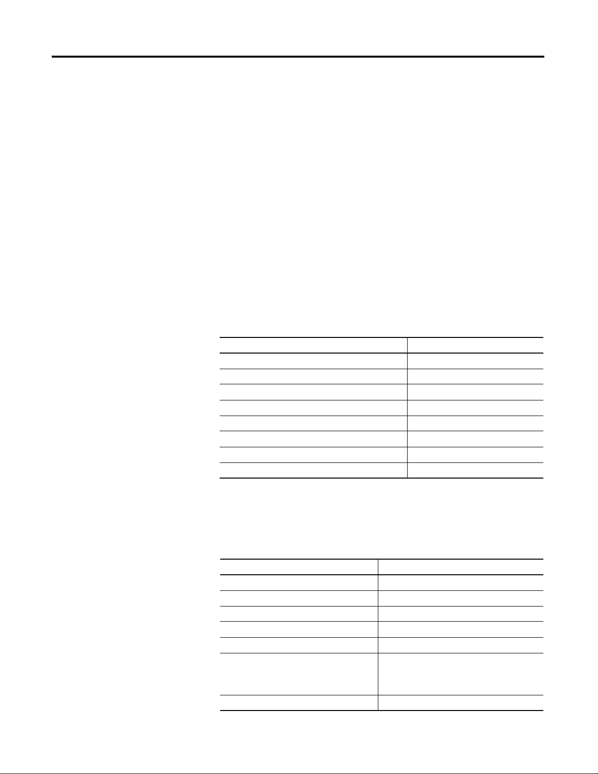
New Information
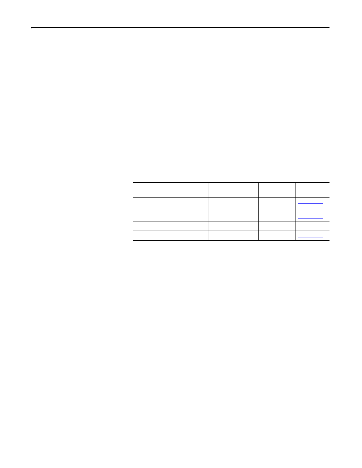
See the table that shows what we added to this publication.
Item Added Cat. No.
Input Modules 1734-IA4
1734-IB4D
1734-IM4
Output Modules 1734-OA4
Specialty Modules 1734-IR2E
One-piece Terminal Bases 1734-TOP, 1734-TOPS
1734-TOP3, 1734-TOP3S
Revised Information
We updated additional information as necessary to more fully explain certain
procedures.
Change Bars
Change bars (as shown with this paragraph) show the areas in this manual that
are different from previous editions and indicate the addition of new or
revised information.
Publication 1734-UM001E-EN-P - July 2013
Page 4

iv Summary of Changes
Notes:
Publication 1734-UM001E-EN-P - July 2013
Page 5
Preface
Purpose of This Manual
This manual describes how to install, configure, and troubleshoot your
POINT I/O modules.
The POINT I/O modules in this manual are DeviceNet ready. Each module can
exist on the DeviceNet network as one of the following:
• As an individual node
• With an adapter (catalog number 1734-ADN or 1734-ADNX) as a single
node
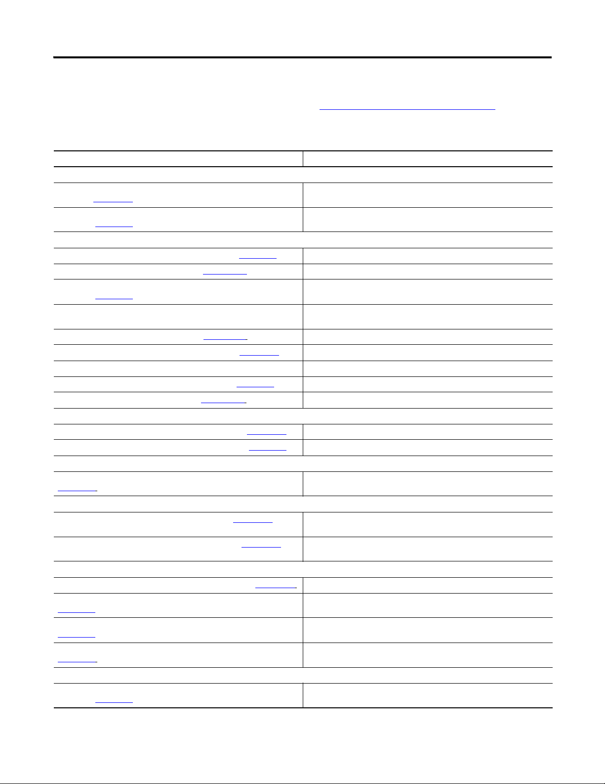
When using these POINT I/O modules with an adapter, use this manual in
conjunction with the user manual for the adapter you are using as shown in the
table.
For applications using these modules in a network with a 1734-PDN DeviceNet
Communication Interface, or a 1734D-xx POINTBlock I/O module, this user
manual is the primary documentation.
When Using POINT I/O Modules
on This Network
DeviceNet network DeviceNet adapter 1734-ADN
ControlNet network ControlNet adapter 1734-ACNR 1734-UM008
EtherNet/IP network EtherNet/IP adapter 1734-AENT 1734-UM011
PROFIBUS network PROFIBUS adapter 1734-APB 1734-UM005
Refer to User
Manual for
Cat. No. Publication
No.
1734-UM002
1734-ADNX
Who Should Use This Manual
In this manual, we assume you know how to do the following:
• Use RSNetWorx software or similar configuration software to set up and
calibrate these modules.
• Have the capability to download and use electronic data sheet (EDS) files.
If you do not, refer to your software documentation or online help before
attempting to use these modules.
Rockwell Automation Publication 1734-UM001E-EN-P - July 2013
Page 6
xiv Preface
Additional Resources
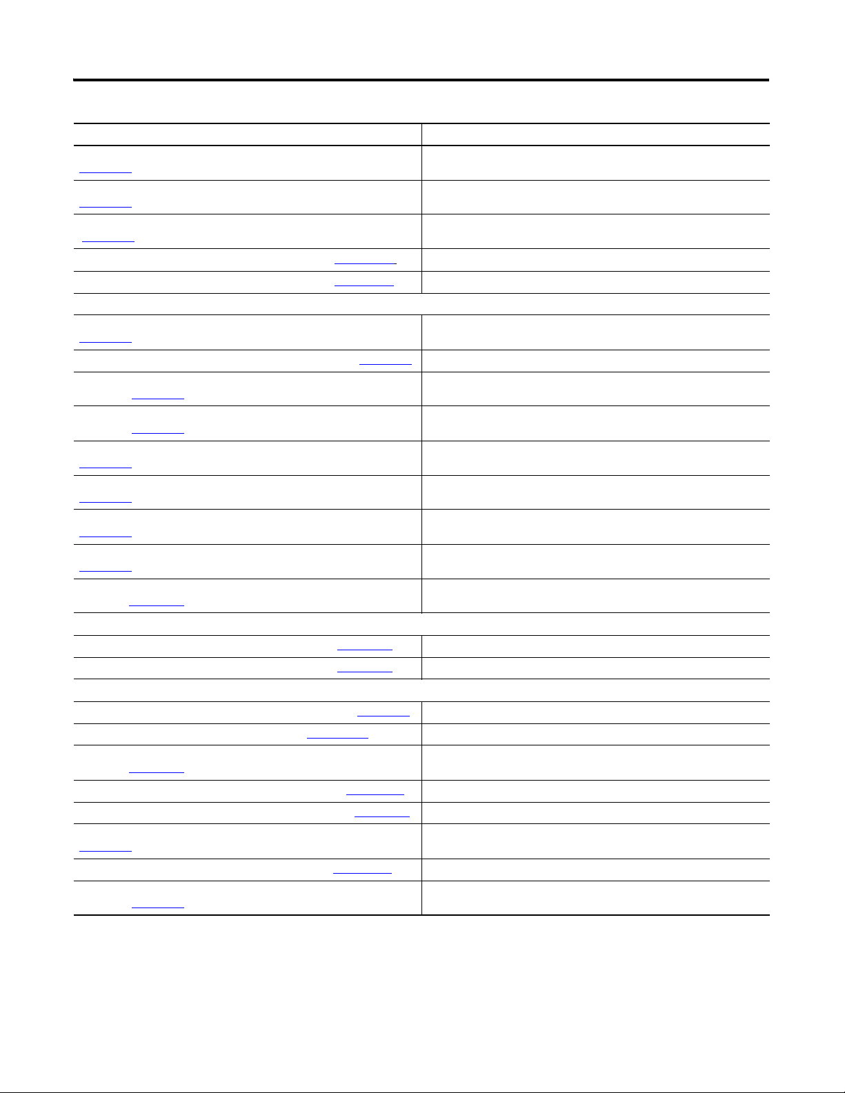
Refer to this table for a list of related 1734 products and documentation. Most of
these are available from http://literature.rockwellautomation.com/
. For
specification and safety certification information, refer to the installation
instructions.
Resource Description
Analog Modules
Analog Current and Voltage Input Module Installation Instructions,
publication 1734-IN027
Analog Current and Voltage Output Module Installation Instructions,
publication 1734-IN002
Communication Devices
ControlNet Adapter Installation Instructions, publication 1734-IN582 Provides installation information about 1734-ACNR adapters
ControlNet Adapter User Manual, publication 1734-UM008
DeviceNet Communication Interface Module Installation Instructions,
publication 1734-IN057
DeviceNet Adapter Installation Instructions, publication 1734-IN026 Provides installation information about 1734-ADN and 1734-ADNX
DeviceNet Adapter User Manual, publication 1734-UM002
EtherNet/IP Adapter Installation Instructions, publication 1734-IN590 Provides installation information about 1734-AENT adapters
EtherNet/IP Adapter User Manual, publication 1734-UM011 Describes how to use 1734-AENT adapters
PROFIBUS Adapter Installation Instructions, publication 1734-IN014
PROFIBUS Adapter User Manual, publication 1734-UM005 Describes how to use 1734-APB adapters
Digital AC Input Modules
220V AC Input Module Installation Instructions, publication 1734-IN008
120V AC Input Module Installation Instructions, publication 1734-IN010 Provides installation information about 1734-IA2 and 1734-IA4 modules
Digital AC Output Modules
120/220V AC Output Module Installation Instructions, publication
1734-IN009
Digital DC Input Modules
Sink Input Module Installation Instructions, publication 1734-IN051 Provides installation information about 1734-IB2, 1734-IB4, and 1734-IB8
Source Input Module Installation Instructions, publication 1734-IN052
Digital DC Output Modules
Protected Output Module Installation Instructions, publication 1734-IN586 Provides installation information about 1734-OB2EP modules
Protected Sink Output Module Installation Instructions, publication
1734-IN585
Protected Source Output Module Installation Instructions, publication
1734-IN056
Protected Source Output Module Installation Instructions, publication
1734-IN018
POINTBlock Modules
8 AC Input/8 AC Output Module Installation Instructions,
publication 1734-IN022
Describes how to use 1734-ADN and 1734-ADNX adapters
Provides installation information about 1734-APB adapters
Provides installation information for 1734-IE2C and 1734-IE2V input
modules
Provides installation information about 1734-OE2C and 1734-OE2V modules
Describes how to use 1734-ACNR adapters
Provides installation information about 1734-PDN modules
adapters
Provides installation information about 1734-IM2 and 1734-IM4 modules
Provides installation information about 1734-OA2 and 1734-OA4 modules
modules
Provides installation information about 1734-IV2, 1734-IV4, and 1734-IV8
modules
Provides installation information about 1734-OV2E, 1734-OV4E, and
1734-OV8E modules
Provides installation information about 1734-OB2E, 1734-OB4E, and
1734-OB8E modules
Provides installation information about 1734-OB2, 1734-OB4, and 1734-OB8
modules
Provides installation information about 1734D-IA8XOA8 modules
Rockwell Automation Publication 1734-UM001E-EN-P - July 2013
Page 7
Preface xv
Resource Description
8 AC Input/8 AC Relay Output Module Installation Instructions, publication
1734-IN023
8 DC Input/8 Output Module Installation Instructions, publication
1734-IN020
8 DC Input/8 DC Output Module Installation Instructions, publication
1734-IN021
16 AC Input Module Installation Instructions, publication 1734D-IN001 Provides installation information about 1734D-IA16 modules
16 DC Input Module Installation Instructions, publication 1734D-IN002 Provides installation information about 1734D-IB16 modules
Power Supplies, Wiring Base Assemblies, Miscellaneous
Cold Junction Wiring Base Assembly Installation Instructions, publication
1734-IN583
Field Potential Distributor Installation Instructions, publication 1734-IN059 Provides installation information about 1734-FPD distributors
POINT I/O 24V DC Expansion Power Supply Installation Instructions,
publication 1734-IN058
POINT I/O 120/240V AC Expansion Power Supply Installation Instructions,
publication 1734-IN017
POINT I/O Common Terminal Module Installation Instructions, publication
1734-IN024
POINT I/O Voltage Terminal Module Installation Instructions, publication
1734-IN024
POINT I/O Wiring Base Assembly Installation Instructions, publication
1734-IN511
POINT I/O Wiring Base Assembly Installation Instructions, publication
1734-IN013
POINT I/O One-piece Wiring Base Assembly Installation Instructions,
publication 1734-IN028
Relay Modules
Relay Output Module Installation Instructions, publication 1734-IN055 Provides installation information about 1734-OW2 and 1734-OW4 modules
Relay Output Module Installation Instructions, publication 1734-IN587
Specialty Modules
Encoder/Counter Module Installation Instructions, publication 1734-IN005 Provides installation information about 1734-IJ and 1734-IK modules
Encoder/Counter Module User Manual, publication 1734-UM006
Very High-speed Counter Module Installation Instructions,
publication 1734-IN003
Very High-speed Counter Module User Manual, publication 1734-UM003
Address Reserve Module Installation Instructions, publication 1734-IN019
ASCII RS-232 and 485 Module Installation Instructions, publication
1734-IN588
ASCII RS-232 and 485 Module User Manual, publication 1734-UM009
RTD and Isolated Thermocouple Input Module Installation Instructions,
publication 1734-IN011
Provides installation information about 1734D-IA8XOW8 modules
Provides installation information about 1734D-IB8XOB8 modules
Provides installation information about 1734D-IB8XOW8 modules
Provides installation information about 1734-TBCJC assemblies
Provides installation information about 1734-EP24DC power supplies
Provides installation information about 1734-EPAC power supplies
Provides installation information about 1734-CTM modules
Provides installation information about 1734-VTM modules
Provides installation information about 1734-TB and 1734-TBS assemblies
Provides installation information about 1734-TB3 and 1734-TB3S
assemblies
Provides installation information about 1734-TOP, 1734-TOPS, 1734-TOP3
and 1734-TOP3S assemblies
Provides installation information about 1734-OX2 modules
Describes how to use 1734-IJ and 1734-IK modules
Provides installation information about 1734-VHSC5 and 1734-VHSC24
modules
Describes how to use 1734-VHSC5 and 1734-VHSC24 modules
Provides installation information about 1734-ARM modules
Provides installation information about 1734-232ASC and 1734-485ASC
modules
Describes how to use 1734-232ASC and 1734-485ASC modules
Provides installation information about 1734-IR2, 1734-IT2I, and 1734-IR2E
modules
Rockwell Automation Publication 1734-UM001E-EN-P - July 2013
Page 8

xvi Preface
Resource Description
RTD and Isolated Thermocouple Input User Manual, publication
1734-UM004
Synchronous Serial Interface Encoder Module Installation Instructions,
publication 1734-IN581
Synchronous Serial Interface Encoder Module User Manual, publication
1734-UM007
Describes how to use 1734-IR2, 1734-IT2I, and 1734-IR2E modules
Provides installation information about 1734-SSI modules
Describes how to use 1734-SSI modules
Rockwell Automation Publication 1734-UM001E-EN-P - July 2013
Page 9

Table of Contents
Preface
Purpose of This Manual. . . . . . . . . . . . . . . . . . . . . . . . . . . . . . . . . . . . . . . . . . . 13
Who Should Use This Manual . . . . . . . . . . . . . . . . . . . . . . . . . . . . . . . . . . . . 13
Additional Resources . . . . . . . . . . . . . . . . . . . . . . . . . . . . . . . . . . . . . . . . . . . . . 14
Chapter 1
About the Modules
Install POINT I/O Modules
About This Chapter . . . . . . . . . . . . . . . . . . . . . . . . . . . . . . . . . . . . . . . . . . . . . . 17
Digital Modules . . . . . . . . . . . . . . . . . . . . . . . . . . . . . . . . . . . . . . . . . . . . . . . . . . 17
Input Modules . . . . . . . . . . . . . . . . . . . . . . . . . . . . . . . . . . . . . . . . . . . . . . . 18
Output Modules. . . . . . . . . . . . . . . . . . . . . . . . . . . . . . . . . . . . . . . . . . . . . . 18
Relay Output Modules . . . . . . . . . . . . . . . . . . . . . . . . . . . . . . . . . . . . . . . . 19
Analog Modules. . . . . . . . . . . . . . . . . . . . . . . . . . . . . . . . . . . . . . . . . . . . . . . . . . 20
Input Modules . . . . . . . . . . . . . . . . . . . . . . . . . . . . . . . . . . . . . . . . . . . . . . . 21
Output Modules. . . . . . . . . . . . . . . . . . . . . . . . . . . . . . . . . . . . . . . . . . . . . . 21
Specialty Modules . . . . . . . . . . . . . . . . . . . . . . . . . . . . . . . . . . . . . . . . . . . . . . . . 22
Power Supplies, Wiring Base Assemblies, and Miscellaneous Modules. 22
Chapter 2
About This Chapter . . . . . . . . . . . . . . . . . . . . . . . . . . . . . . . . . . . . . . . . . . . . . . 23
Install the Mounting Base Assembly . . . . . . . . . . . . . . . . . . . . . . . . . . . . . . . 24
Install an I/O Module . . . . . . . . . . . . . . . . . . . . . . . . . . . . . . . . . . . . . . . . . . . . 26
Install the Removable Terminal Block. . . . . . . . . . . . . . . . . . . . . . . . . . . . . . 28
Remove a Mounting Base . . . . . . . . . . . . . . . . . . . . . . . . . . . . . . . . . . . . . . . . . 29
Wiring Digital Modules. . . . . . . . . . . . . . . . . . . . . . . . . . . . . . . . . . . . . . . . . . . 30
1734-IB2, 1734-IB4, and 1734-IB8 Sink Input Modules . . . . . . . . . 30
1734-IB4D Modules . . . . . . . . . . . . . . . . . . . . . . . . . . . . . . . . . . . . . . . . . 34
1734-IV2, 1734-IV4, and 1734-IV8 Source Input Modules . . . . . . 35
1734-OB2E, 1734-OB4E, 1734-OB8E, 1734-OB2,
1734-OB4, and 1734-OB8 Protected Output Modules . . . . . . . . . . 38
1734-OB2EP Protected Output Modules. . . . . . . . . . . . . . . . . . . . . . . 41
1734-OW2 and 1734-OW4 Relay Output Module s . . . . . . . . . . . . 42
1734-OW2 Modules with Load Powered by Internal Power Bus
Wiring Diagram . . . . . . . . . . . . . . . . . . . . . . . . . . . . . . . . . . . . . . . . . . . . . . 42
1734-OW2 Modules with Load Powered by
External Power Wiring Diagram . . . . . . . . . . . . . . . . . . . . . . . . . . . . . . . 43
1734-OW4 Modules with Load Powered by
External Power Wiring Diagram . . . . . . . . . . . . . . . . . . . . . . . . . . . . . . . 44
1734-OV2E, 1734-OV4E, and 1734-OV8E
Sink Output Modules. . . . . . . . . . . . . . . . . . . . . . . . . . . . . . . . . . . . . . . . . 47
1734-OX2 2-relay Output Modules. . . . . . . . . . . . . . . . . . . . . . . . . . . . 49
1734-OX2 Module with Load Powered by
Internal Power Bus Wiring Diagram . . . . . . . . . . . . . . . . . . . . . . . . . . 50
1734-OX2 Modules with Load Powered by External Power Bus
Wiring Diagram . . . . . . . . . . . . . . . . . . . . . . . . . . . . . . . . . . . . . . . . . . . . 50
Rockwell Automation Publication 1734-UM001E-EN-P - July 2013
Page 10

xviii
1734-IA2 and 1734-IA4 120 V AC Input Modules . . . . . . . . . . . . . 53
1734-IM2 and 1734-IM4 220V AC Input Modules . . . . . . . . . . . . . 55
1734-IM2 120V AC 2 Input Module Wiring Diagram . . . . . . . . . . 55
1734-IM4 2 Input Module Wiring Diagram . . . . . . . . . . . . . . . . . . . . 56
1734-OA2 and 1734- OA4 120/220V AC Output Modules . . . . . 57
1734-OA2 AC 2 Output Module Wiring Diagram. . . . . . . . . . . . . . 57
1734-OA4 AC 2 Output Module Wiring Diagram. . . . . . . . . . . . . . 58
Wiring Analog Modules . . . . . . . . . . . . . . . . . . . . . . . . . . . . . . . . . . . . . . . . . . 59
1734-IE2C Analog Current Input Module . . . . . . . . . . . . . . . . . . . . . 59
1734-IE2C Analog Current Input Module Wiring Diagram . . . . . 59
1734-IE2V Analog Voltage Input Module . . . . . . . . . . . . . . . . . . . . . . 60
1734-IE2V Analog Voltage Input Module Wiring Diagram. . . . . . 60
1734-OE2C Analog Current Output Module . . . . . . . . . . . . . . . . . . 61
1734-OE2C Analog Current Output Module
Wiring Diagram. . . . . . . . . . . . . . . . . . . . . . . . . . . . . . . . . . . . . . . . . . . . . . 61
1734-OE2V Analog Voltage Output Module . . . . . . . . . . . . . . . . . . . 62
1734-OE2V Analog Voltage Output Module
Wiring Diagram. . . . . . . . . . . . . . . . . . . . . . . . . . . . . . . . . . . . . . . . . . . . . . 62
Wiring Power Distribution and Other Modules . . . . . . . . . . . . . . . . . . . . 63
1734-PDN Communication Interface Module. . . . . . . . . . . . . . . . . . 63
1734-PDN Module Wiring Diagram . . . . . . . . . . . . . . . . . . . . . . . . . . 63
1734-FPD Field Potential Distributor Module. . . . . . . . . . . . . . . . . . 65
1734-FPD Modules for 12/24V DC Wiring Diagram . . . . . . . . . . . 65
1734-EP24DC Expansion Power Supply . . . . . . . . . . . . . . . . . . . . . . . 68
12/24v DC Wiring Diagram . . . . . . . . . . . . . . . . . . . . . . . . . . . . . . . . . . 68
1734-EPAC AC Expansion Power Supply. . . . . . . . . . . . . . . . . . . . . . 71
120/240V AC Wiring Diagram . . . . . . . . . . . . . . . . . . . . . . . . . . . . . . . 72
1734-ARM Address Reserve Module. . . . . . . . . . . . . . . . . . . . . . . . . . . 74
1734-CTM and 1734-VTM Modules . . . . . . . . . . . . . . . . . . . . . . . . . . 74
Sink Input Wiring Diagram . . . . . . . . . . . . . . . . . . . . . . . . . . . . . . . . . . . 75
Source Input Wiring Diagram . . . . . . . . . . . . . . . . . . . . . . . . . . . . . . . . . 75
Source Output Wiring Diagram . . . . . . . . . . . . . . . . . . . . . . . . . . . . . . 76
Sink Output Wiring Diagram . . . . . . . . . . . . . . . . . . . . . . . . . . . . . . . . . 76
General Purpose Wiring Diagram . . . . . . . . . . . . . . . . . . . . . . . . . . . . . 76
Rockwell Automation Publication 1734-UM001E-EN-P - July 2013
Page 11

Chapter 3
xix
Install POINTBlock I/O Modules
About This Chapter . . . . . . . . . . . . . . . . . . . . . . . . . . . . . . . . . . . . . . . . . . . . . . 77
Wiring POINTBlock Modules . . . . . . . . . . . . . . . . . . . . . . . . . . . . . . . . . . . . 78
1734D-IB8XOB8 POINTBlock 8 DC In/8 DC Out Modules. . . 78
8 Input/8 Output Module Wiring Diagram . . . . . . . . . . . . . . . . . . . . 78
Sink Input Wiring Diagram . . . . . . . . . . . . . . . . . . . . . . . . . . . . . . . . . . . 79
Output Wiring Diagram . . . . . . . . . . . . . . . . . . . . . . . . . . . . . . . . . . . . . . 80
1734D-IB8XOW8 POINTBlock 8 DC In/8 Relay
Out Modules. . . . . . . . . . . . . . . . . . . . . . . . . . . . . . . . . . . . . . . . . . . . . . . . . 82
8 Input/8 Relay Output Module Wiring Diagram. . . . . . . . . . . . . . . 82
Sink Input Wiring . . . . . . . . . . . . . . . . . . . . . . . . . . . . . . . . . . . . . . . . . . . . 82
Output Wiring Diagram (Load Powered by
External Power) . . . . . . . . . . . . . . . . . . . . . . . . . . . . . . . . . . . . . . . . . . . . . . 84
1734D-IA8XOA8 POINTBlock 8 AC In/8 AC Out Modules. . . 85
1734D-IA8XOA8 POINTBlock 8 AC In/8 AC Out Modules
Wiring Diagram . . . . . . . . . . . . . . . . . . . . . . . . . . . . . . . . . . . . . . . . . . . . . . 85
Input Wiring Diagram . . . . . . . . . . . . . . . . . . . . . . . . . . . . . . . . . . . . . . . . 86
Output Wiring Diagram . . . . . . . . . . . . . . . . . . . . . . . . . . . . . . . . . . . . . . 87
1734D-IA8XOW8 POINTBlock 8 AC In/8 Relay
Out Modules. . . . . . . . . . . . . . . . . . . . . . . . . . . . . . . . . . . . . . . . . . . . . . . . . 88
1734D-IA8XOW8 POINTBlock 8 AC In/8 Relay
Out Modules Wiring Diagram. . . . . . . . . . . . . . . . . . . . . . . . . . . . . . . . . 88
Input Wiring Diagram . . . . . . . . . . . . . . . . . . . . . . . . . . . . . . . . . . . . . . . . 89
Output Wiring Diagram . . . . . . . . . . . . . . . . . . . . . . . . . . . . . . . . . . . . . . 90
1734D-IA16 POINTBlock 16 AC Input Modules . . . . . . . . . . . . . . 91
Wire the 16 AC Input Module Wiring Diagram . . . . . . . . . . . . . . . . 91
Input Wiring Diagram . . . . . . . . . . . . . . . . . . . . . . . . . . . . . . . . . . . . . . . . 92
1734D-IB16 POINTBlock 16 DC Input Modules . . . . . . . . . . . . . . 94
16 DC Input Module Wiring Diagram . . . . . . . . . . . . . . . . . . . . . . . . . 94
Sink Input Wiring Diagram . . . . . . . . . . . . . . . . . . . . . . . . . . . . . . . . . . 95
Rockwell Automation Publication 1734-UM001E-EN-P - July 2013
Page 12

xx
Chapter 4
POINT I/O Module Data
About This Chapter. . . . . . . . . . . . . . . . . . . . . . . . . . . . . . . . . . . . . . . . . . . . . . 97
Digital Input Modules . . . . . . . . . . . . . . . . . . . . . . . . . . . . . . . . . . . . . . . . . . . . 97
Digital DC Input Modules . . . . . . . . . . . . . . . . . . . . . . . . . . . . . . . . . . . . 97
Digital AC Input Modules . . . . . . . . . . . . . . . . . . . . . . . . . . . . . . . . . . . . 99
Digital Output Modules . . . . . . . . . . . . . . . . . . . . . . . . . . . . . . . . . . . . . . . . . 100
Digital DC Output Modules . . . . . . . . . . . . . . . . . . . . . . . . . . . . . . . . . 100
Digital AC Output Modules . . . . . . . . . . . . . . . . . . . . . . . . . . . . . . . . . 102
Relay Output Modules . . . . . . . . . . . . . . . . . . . . . . . . . . . . . . . . . . . . . . . . . . 103
Analog Input Modules. . . . . . . . . . . . . . . . . . . . . . . . . . . . . . . . . . . . . . . . . . . 104
Data. . . . . . . . . . . . . . . . . . . . . . . . . . . . . . . . . . . . . . . . . . . . . . . . . . . . . . . . 104
Communicate with Your Module. . . . . . . . . . . . . . . . . . . . . . . . . . . . . 105
Scaling. . . . . . . . . . . . . . . . . . . . . . . . . . . . . . . . . . . . . . . . . . . . . . . . . . . . . . 106
Channel Status. . . . . . . . . . . . . . . . . . . . . . . . . . . . . . . . . . . . . . . . . . . . . . 106
Latch Alarms. . . . . . . . . . . . . . . . . . . . . . . . . . . . . . . . . . . . . . . . . . . . . . . . 107
Alarm Disable. . . . . . . . . . . . . . . . . . . . . . . . . . . . . . . . . . . . . . . . . . . . . . . 107
Calibration Status . . . . . . . . . . . . . . . . . . . . . . . . . . . . . . . . . . . . . . . . . . . 107
Digital Filter . . . . . . . . . . . . . . . . . . . . . . . . . . . . . . . . . . . . . . . . . . . . . . . . 108
Update Rate . . . . . . . . . . . . . . . . . . . . . . . . . . . . . . . . . . . . . . . . . . . . . . . . 108
Notch Filter . . . . . . . . . . . . . . . . . . . . . . . . . . . . . . . . . . . . . . . . . . . . . . . . 108
Alarms . . . . . . . . . . . . . . . . . . . . . . . . . . . . . . . . . . . . . . . . . . . . . . . . . . . . . 109
Range Status . . . . . . . . . . . . . . . . . . . . . . . . . . . . . . . . . . . . . . . . . . . . . . . . 109
Channel Indicator Behavior . . . . . . . . . . . . . . . . . . . . . . . . . . . . . . . . . . 110
Analog Output Modules. . . . . . . . . . . . . . . . . . . . . . . . . . . . . . . . . . . . . . . . . 110
Data. . . . . . . . . . . . . . . . . . . . . . . . . . . . . . . . . . . . . . . . . . . . . . . . . . . . . . . . 110
Operational Modes . . . . . . . . . . . . . . . . . . . . . . . . . . . . . . . . . . . . . . . . . . 112
Scaling. . . . . . . . . . . . . . . . . . . . . . . . . . . . . . . . . . . . . . . . . . . . . . . . . . . . . . 112
Fault and Idle/Program Mode Action . . . . . . . . . . . . . . . . . . . . . . . . . 113
Channel Status. . . . . . . . . . . . . . . . . . . . . . . . . . . . . . . . . . . . . . . . . . . . . . 114
Low and High Clamps . . . . . . . . . . . . . . . . . . . . . . . . . . . . . . . . . . . . . . . 115
Latch Alarms. . . . . . . . . . . . . . . . . . . . . . . . . . . . . . . . . . . . . . . . . . . . . . . . 115
Alarm Disable. . . . . . . . . . . . . . . . . . . . . . . . . . . . . . . . . . . . . . . . . . . . . . . 115
Channel Indicators . . . . . . . . . . . . . . . . . . . . . . . . . . . . . . . . . . . . . . . . . . 116
POINTBlock I/O Modules . . . . . . . . . . . . . . . . . . . . . . . . . . . . . . . . . . . . . . 116
Rockwell Automation Publication 1734-UM001E-EN-P - July 2013
Page 13

Chapter 5
xxi
Calibrate Your Analog Modules
Troubleshoot with the
Indicators
About This Chapter . . . . . . . . . . . . . . . . . . . . . . . . . . . . . . . . . . . . . . . . . . . . . 121
Tools Required to Calibrate Your Analog Modules. . . . . . . . . . . . . . . . . 122
Calibrate the Analog Current Input Module. . . . . . . . . . . . . . . . . . . . . . . 123
Calibrate the Analog Current Output Module. . . . . . . . . . . . . . . . . . . . . 127
Calibrate the Analog Voltage Input Module . . . . . . . . . . . . . . . . . . . . . . . 132
Calibrate the Analog Voltage Output Module . . . . . . . . . . . . . . . . . . . . . 136
Chapter 6
About This Chapter . . . . . . . . . . . . . . . . . . . . . . . . . . . . . . . . . . . . . . . . . . . . . 141
About Module Diagnostics . . . . . . . . . . . . . . . . . . . . . . . . . . . . . . . . . . . 141
Network and Module Status Indications. . . . . . . . . . . . . . . . . . . . . . . 142
Troubleshoot Digital Modules . . . . . . . . . . . . . . . . . . . . . . . . . . . . . . . . . . . 144
1734-IB2, 1734-IB4, and 1734-IB8 Sink Input Modules . . . . . . . . 144
1734-IB4D Sink Input Modules with Diagnostics . . . . . . . . . . . . . . 144
1734-OB2E, 1734-OB4E, and 1734-OB8E Source
Output Modules. . . . . . . . . . . . . . . . . . . . . . . . . . . . . . . . . . . . . . . . . . . . . 145
1734-OB2, 1734-OB4, and 1734-OB8 Source
Output Modules. . . . . . . . . . . . . . . . . . . . . . . . . . . . . . . . . . . . . . . . . . . . . 145
1734-OB2EP Protected Output Module . . . . . . . . . . . . . . . . . . . . . . 146
1734-IV2, 1734-IV4, and 1734-IV8 Source Input Modules . . . . . 146
1734-OV2E, 1734-OV4E, and 1734-OV8E
Protected Sink Output Modules . . . . . . . . . . . . . . . . . . . . . . . . . . . . . . 147
1734-OW2 and 1734-OW4 Relay Output Modules. . . . . . . . . . . . 148
1734-OX2 Relay Output Module. . . . . . . . . . . . . . . . . . . . . . . . . . . . . 149
1734-IA2 and 1734-IA4 120V AC Input Module . . . . . . . . . . . . . . 149
1734-OA2 and 1734-OA4 120/220V AC Output Module . . . . . 150
1734-IM2 and 1734-IM4 220V AC Input Module . . . . . . . . . . . . . 150
Troubleshoot Analog Modules . . . . . . . . . . . . . . . . . . . . . . . . . . . . . . . . . . . 151
1734-IE2C Analog Current Input Module . . . . . . . . . . . . . . . . . . . . 151
1734-OE2C Analog Current Output Module . . . . . . . . . . . . . . . . . 152
1734-IE2V Analog Voltage Input Module . . . . . . . . . . . . . . . . . . . . . 152
1734-OE2V Analog Voltage Output Module. . . . . . . . . . . . . . . . . . 153
Troubleshoot I/O Communication Modules . . . . . . . . . . . . . . . . . . . . . . 154
1734-ADN (X) DeviceNet Adapter. . . . . . . . . . . . . . . . . . . . . . . . . . . 155
1734-ACNR ControlNet Adapter . . . . . . . . . . . . . . . . . . . . . . . . . . . . 157
1734-APB PROFIBUS Adapter . . . . . . . . . . . . . . . . . . . . . . . . . . . . . . 160
1734-AENT EtherNet/IP Adapter . . . . . . . . . . . . . . . . . . . . . . . . . . . 162
Rockwell Automation Publication 1734-UM001E-EN-P - July 2013
Page 14

xxii
Appendix A
Default Data Maps
About This Appendix . . . . . . . . . . . . . . . . . . . . . . . . . . . . . . . . . . . . . . . . . . . 165
Digital Module Default Data Maps . . . . . . . . . . . . . . . . . . . . . . . . . . . . . . . 166
1734-IB2 Sink Input Module. . . . . . . . . . . . . . . . . . . . . . . . . . . . . . . . . 166
1734-IB4 Sink Input Module. . . . . . . . . . . . . . . . . . . . . . . . . . . . . . . . . 166
1734-IB8 Sink Input Module. . . . . . . . . . . . . . . . . . . . . . . . . . . . . . . . . 166
1734-IB4D Sink Input Modules with Diagnostics. . . . . . . . . . . . . . 167
1734-IV2 Source Input Module . . . . . . . . . . . . . . . . . . . . . . . . . . . . . . 168
1734-IV4 Source Input Module . . . . . . . . . . . . . . . . . . . . . . . . . . . . . . 168
1734-IV8 Source Input Module . . . . . . . . . . . . . . . . . . . . . . . . . . . . . . 168
1734-IA2 Input Module . . . . . . . . . . . . . . . . . . . . . . . . . . . . . . . . . . . . . 169
1734-IA4 Input Module . . . . . . . . . . . . . . . . . . . . . . . . . . . . . . . . . . . . . 169
1734-IM2 Input Module. . . . . . . . . . . . . . . . . . . . . . . . . . . . . . . . . . . . . 169
1734-IM4 Input Module. . . . . . . . . . . . . . . . . . . . . . . . . . . . . . . . . . . . . 169
1734-OA2 Output Module . . . . . . . . . . . . . . . . . . . . . . . . . . . . . . . . . . 170
1734-OA4 Output Module . . . . . . . . . . . . . . . . . . . . . . . . . . . . . . . . . . 170
1734-OB2E, 1734-OB2 Electronically Protected
Output Module . . . . . . . . . . . . . . . . . . . . . . . . . . . . . . . . . . . . . . . . . . . . . 170
1734-OB4E, 1734-OB4 Electronically Protected
Output Module . . . . . . . . . . . . . . . . . . . . . . . . . . . . . . . . . . . . . . . . . . . . . 171
1734-OB8E, 1734-OB8 Electronically Protected
Output Module . . . . . . . . . . . . . . . . . . . . . . . . . . . . . . . . . . . . . . . . . . . . . 171
1734-OB2EP Protected Output Module . . . . . . . . . . . . . . . . . . . . . . 171
1734-OV2E Output Module . . . . . . . . . . . . . . . . . . . . . . . . . . . . . . . . . 172
1734-OV4E Output Module . . . . . . . . . . . . . . . . . . . . . . . . . . . . . . . . . 172
1734-OV8E Output Module . . . . . . . . . . . . . . . . . . . . . . . . . . . . . . . . . 173
1734-OW2 Relay Sink/Source Output Module. . . . . . . . . . . . . . . . 173
1734-OW4 Relay Sink/Source Output Module. . . . . . . . . . . . . . . . 173
1734-OX2 Relay Output Module. . . . . . . . . . . . . . . . . . . . . . . . . . . . . 174
Analog Module Default Data Maps. . . . . . . . . . . . . . . . . . . . . . . . . . . . . . . 174
1734-IE2C Analog Current Input Module . . . . . . . . . . . . . . . . . . . . 174
1734-IE2V Analog Voltage Input Module . . . . . . . . . . . . . . . . . . . . . 175
1734-OE2C Analog Current Output Module . . . . . . . . . . . . . . . . . 175
1734-OE2V Analog Voltage Output Module . . . . . . . . . . . . . . . . . . 176
Appendix B
Mounting Dimensions
Rockwell Automation Publication 1734-UM001E-EN-P - July 2013
About This Appendix . . . . . . . . . . . . . . . . . . . . . . . . . . . . . . . . . . . . . . . . . . . 179
POINT I/O Module with a 1734-ADN, 1734-ACNR,
1734-AENT, or 1734-APB Adapter . . . . . . . . . . . . . . . . . . . . . . . . . . . . . . 180
POINT I/O Module with a 1734-PDN Module. . . . . . . . . . . . . . . . . . . 181
POINTBlock Module . . . . . . . . . . . . . . . . . . . . . . . . . . . . . . . . . . . . . . . . . . . 182
Page 15

Appendix C
xxiii
Configure POINT I/O Modules in
RSLogix 5000 Software
About This Appendix . . . . . . . . . . . . . . . . . . . . . . . . . . . . . . . . . . . . . . . . . . . 183
Use the Help Button . . . . . . . . . . . . . . . . . . . . . . . . . . . . . . . . . . . . . . . . . . . . 183
Configure Digital Modules. . . . . . . . . . . . . . . . . . . . . . . . . . . . . . . . . . . . . . . 183
Configure Analog Modules . . . . . . . . . . . . . . . . . . . . . . . . . . . . . . . . . . . . . . 195
Appendix D
Configure POINT I/O Modules
for DeviceNet Networks
About This Appendix . . . . . . . . . . . . . . . . . . . . . . . . . . . . . . . . . . . . . . . . . . . 211
Configuring POINT I/O Modules . . . . . . . . . . . . . . . . . . . . . . . . . . . . . . . 211
Commissioning a Node . . . . . . . . . . . . . . . . . . . . . . . . . . . . . . . . . . . . . . . . . . 211
Configure Digital Modules Using RSNetWorx Software . . . . . . . . . . . 213
Configure Analog Modules Using RSNetWorx Software . . . . . . . . . . . 227
About Fault/Program Action and Configuration Dialogs . . . . . . . 186
Understanding Data and Connection Formats . . . . . . . . . . . . . . . . . 186
Understanding Transition to Hard Run Behavior . . . . . . . . . . . . . . 187
Working with Dialogs for Digital Input Modules. . . . . . . . . . . . . . . 188
Working with Dialogs for Digital Output Modules. . . . . . . . . . . . . 190
Understanding Data and Connection Formats . . . . . . . . . . . . . . . . . 196
Working with Dialogs for Analog Input Modules . . . . . . . . . . . . . . 197
Working with Dialogs for Analog Output Modules . . . . . . . . . . . . 203
Using the RSNetWorx Commissioning Tool . . . . . . . . . . . . . . . . . . 211
Use Sequential Auto Addressing . . . . . . . . . . . . . . . . . . . . . . . . . . . . . . 213
Using Third-party Configuration Software . . . . . . . . . . . . . . . . . . . . 213
Index
Rockwell Automation Publication 1734-UM001E-EN-P - July 2013
Page 16

xxiv
Notes:
Rockwell Automation Publication 1734-UM001E-EN-P - July 2013
Page 17

About the Modules
Chapter
1
About This Chapter
Digital Modules
This chapter introduces POINT I/O and related modules to include the
following:
• Digital modules
• Relay output modules
• Analog modules
• Specialty modules
• Power supplies, wiring base assemblies, and miscellaneous modules
This table lists the1734 digital modules.
Digital Module Description Cat. No.
2, 4, and 8 sink input modules 1734-IB2, 1734-IB4, 1734-IB8, 1734-IB4D
2, 4, and 8 source input modules 1734-IV2, 1734-IV4, 1734-IV8
2, 4, and 8 sink output modules 1734-OV2E, 1734-OV4E, 1734-OV8E
2, 4, and 8 protected
source output modules
2 protected source output modules 1734-OB2EP
2 and 4 relay output modules 1734-OW2, 1734-OW4
2 relay output modules 1734-OX2
2 120/220V AC output modules 1734-OA2, 1734-OA4
2 120V AC input modules 1734-IA2, 1734-IA4
2 240V AC input modules 1734-IM2, 1734-IM4
1734-OB2, 1734-OB4, 1734-OB8,
1734-OB2E, 1734-OB4E, 1734-OB8E
This table lists the 1734D POINTBlock modules.
POINTBlock Module Description Cat. No.
8 AC input and 8 AC output 1734D-IA8XOA8 and 1734-IA8XOA8S
8 AC input and 8 relay output 1734D-IA8XOW8 and 1734-IA8XOW8S
8 DC input and 8 DC output 1734D-IB8XOB8 and 1734-IB8XOB8S
8 DC input and 8 relay output 1734D-IB8XOW8 and 1734-IB8XOW8S
16 AC input 1734D-IA16 and 1734-IA16S
16 DC input 1734D-IB16 and 1734-IB16S
Rockwell Automation Publication 1734-UM001E-EN-P - July 2013
Page 18

2 About the Modules
Input Modules
For input modules, DC inputs are 24V DC nominal, with an input range of
10…28.8V dc, and are offered with 2, 4,or 8 sinking style inputs, or 2, 4, or 8
sourcing style inputs. The 1734-IB2, 1734-IB4, 1734-IB4D, and 1734-IB8 input
modules are sinking modules. The 1734-IV2, 1734-IV4, and 1734-IV8 modules
are sourcing input modules.
For input modules, AC inputs are 120V AC nominal with an input range of
85…132V ac, or 220V AC nominal with an input range of 159…264V ac, with
sinking inputs.
Features of the all input modules include the following:
• Autobaud (will match baud of existing devices on the network)
• Selectable input filter times (0…65 ms with 1 ms default)
• Sequential auto addressing
Output Modules
The 1734-OB2, 1734-OB4, 1734-OB8, 1734-OB2E, 1734-OB4E, and 1734-
OB8E DC output modules have current limited sourcing outputs, which source a
positive voltage of up to 1 A with respect to their DC return per channel. The
1734-OB2EP sources a positive voltage of up to 2 A with respect to its DC
return per channel. The outputs are not isolated from each other. For these
modules, DC outputs are 24V DC nominal, with a range of 10…28.8V dc. A
number of output diagnostic features are incorporated to assist in
troubleshooting. The 1734-OB2E, 1734-OB2EP, 1734-OB4E, and 1734-OB8E
modules feature the following:
• Output diagnostics (short circuit and wire-off indication and reporting
bits per channel)
• Current limited outputs
• Autobaud (will match baud of existing devices on the network)
• Sequential auto addressing
The 1734-OV2E, 1734-OV4E, and 1734-OV8E modules are protected sink
output modules protected to 1 A. The outputs are not isolated from each other.
For these modules, DC outputs are 24V DC nominal, with a range of 10…28.8V
dc. A number of output diagnostic features are incorporated to assist in
troubleshooting. The 1734-OV2E, 1734-OV4E, and 1734-OV8E modules
feature the following (note that 1734-OV2E, 1734-OV4E, and 1734-OV8E
modules have no wire-off indication):
• Output diagnostics (short circuit and reporting bits per channel)
• Current limited outputs
• Autobaud (will match baud of existing devices on the network)
• Sequential auto addressing
Rockwell Automation Publication 1734-UM001E-EN-P - July 2013
Page 19

About the Modules 3
The 1734-OA2 and 1734-OA4 AC output modules have sourcing outputs,
which source a voltage of up to 0.75 A per channel. The outputs are not isolated
from each other. For this module, AC outputs are 120/220V AC nominal, with a
range of 74…264V dc. The 1734-OA2 and 1734-OA4 modules feature the
following:
• Autobaud (will match baud of existing devices on the network)
• Sequential auto addressing
Relay Output Modules
Two versions of relay modules are:
• 1734-OW2, 1734-OW4 relay module.
• 1734-OX2 relay module.
The 1734-OW2 and 1734-OW4 relay outputs are Type A (Normally Open),
the 1734-OX2 relay outputs are Type 2 Form C. Both modules’ outputs sink or
source a current with respect to power or return. Contact outputs are isolated
from each other. Each output is rated 5…240V rms at 2 A (current is load
dependant). Features include:
• Autobaud (will match baud of existing devices on the network).
• Sequential auto addressing.
Analog Modules
The 1734 analog modules consist of input modules (1734-IE2C and 1734IE2V) and output modules (1734-OE2C and 1734-OE2V). Each module has
two single-ended, non-isolated channels.
Cat. No. Module Type Number of
Channels
1734-IE2C Analog Input 2 16 bits across 0…21 mA
1734-IE2V Analog Input 2 15 bits plus sign across -10…10V
1734-OE2C Analog Output 2 13 bits across 0…21 mA
1734-OE2V Analog Output 2 14 bits across -10…10V
Resolution
The features of the analog modules depend on the type of analog module: input
or output. These are features common to both input and output modules.
• Data - The current input and output modules operate in unipolar mode
only. Voltage input and output modules operate in unipolar or bipolar
modes. Data returned from the module is scaled by the user to any 16 bit
signed integer
(–32,768...+32,767).
• Input modules produce 6 bytes of data.
– Channel 0 Data (2 bytes)
– Channel 1 Data (2 bytes)
– Channel 0 Status (1 byte)
Rockwell Automation Publication 1734-UM001E-EN-P - July 2013
Page 20

4 About the Modules
– Channel 1 Status (1 byte)
• Output modules consume 4 bytes of data.
– Channel 0 Data (2 bytes)
– Channel 1 Data (2 bytes)
• Output modules produce 2 bytes of data.
– Channel 0 Status (1 byte)
– Channel 1 Status (1 byte)
• Operational modes
– Current - two modes
• 0 to 20 mA
• 4 to 20 mA (default mode)
– Vol ta ge - t wo m ode s
• 0 to 10V (default mode)
• -10 to +10V
• Individually set channel mode
• Scaling - conversion to engineering units
Input Modules
These features are available on input modules.
• Latching alarms, when set, latch low- and high-alarm status information.
Available alarms include:
– Low.
– Low Low.
– High.
– High High.
• Disable alarms - disables all channel alarms and faults so they are not
reported in the channel status field. Four different alarms are available.
• Settable update rate update rate determines how often an input channel is
scanned.
• Notch filter is selectable for both inputs (50, 60, 250, and
500 Hz).
• Digital filter sets a time constant.
Output Modules
These are features available on output modules.
• Latching alarms, when set, latch low and high clamp alarm status
information.
Rockwell Automation Publication 1734-UM001E-EN-P - July 2013
Page 21
About the Modules 5
• Low and high clamps can be set individually or on a channel basis. When
the output value reaches clamp value, a status bit is set, indicating the
output is clamped.
• Disable alarms - disables all channel alarms and faults so they are not
reported in the channel status field.
• Fault and Idle mode action let you select what happens to the output if
a fault occurs or if the module is in idle mode. The choices are the
following:
– Hold Last State
– Low Clamp
– High Clamp
– User-defined va lue
Specialty Modules
Power Supplies, Wiring Base Assemblies, and Miscellaneous Modules
For more information about the following 1734 specialty modules, refer to the
installation instructions and user manuals listed in the Related Products and
Documentation section of this manual.
Module Description Cat. No.
5V Encoder/Counter Module 1734-IJ
24V Encoder/Counter Module 1734-IK
24V Very High-speed Counter Module 1734-VHSC24
5V Very High-speed Counter Module 1734-VHSC5
ASCII RS-232 and RS-485 Module 1734-232ASC, 1734-485ASC
Isolated Thermocouple Input Module 1734-IT2I
RTD Input Module 1734-IR2, 1734-IR2E
Synchronous Serial-interface Encoder Module 1734-SSI
For more information about the following, refer to the installation instructions
and user manuals listed in the Related Products and Documentation section of
this manual.
Module Description Cat. No.
Cold-junction Wiring Base Assembly 1734-TBCJC
Field Potential Distributor 1734-FPD
POINT I/O 24V DC Expansion Power Supply 1734-EP24DC
POINT I/O Common Terminal Module 1734-CTM
POINT I/O Voltage Terminal Module 1734-VTM
Wiring Base Assembly 1734-TB, 1734-TBS,
1734-TB3, 1734-TB3S,
1734-TOP, 1734-TOPS,
1734-TOP3, 1734-TOP3S
Address Reserve Module 1734-ARM
Rockwell Automation Publication 1734-UM001E-EN-P - July 2013
Page 22

6 About the Modules
Notes:
Rockwell Automation Publication 1734-UM001E-EN-P - July 2013
Page 23
Install POINT I/O Modules
Chapter
2
About This Chapter
Read this chapter for installation and wiring information including how to
complete the following:
• Install the mounting base assembly.
• Install an I/O module.
• Install the removable terminal block.
• Remove a mounting base.
• Wire digital modules.
• Wire analog modules.
• Wire power distribution and other modules, such as communication
interface modules, field potential distributor modules, expansion power
supplies, and addressable reserve modules.
Environment and Enclosure
ATTENTION:
This equipment is intended for use in a Pollution Degree 2 industrial
environment, in overvoltage Category II applications (as defined in IEC
publication 60664-1), at altitudes up to 2000 m (6561 ft) without derating.
This equipment is considered Group 1, Class A industrial equipment
according to IEC/CISPR Publication 11. Without appropriate precautions,
there may be potential difficulties ensuring electromagnetic compatibility
in other environments due to conducted as well as radiated disturbance.
This equipment is supplied as open-type equipment. It must be mounted
within an enclosure that is suitably designed for those specific
environmental conditions that will be present and appropriately designed
to prevent personal injury resulting from accessibility to live parts. The
interior of the enclosure must be accessible only by the use of a tool.
Subsequent sections of this publication may contain additional information
regarding specific enclosure type ratings that are required to comply with
certain product safety certifications.
See NEMA Standards publication 250 and IEC publication 60529, as
applicable, for explanations of the degrees of protection provided by
different types of enclosure. Also, see the appropriate sections in this
publication, as well as the Allen-Bradley publication 1770-4.1 (Industrial
Automation Wiring and Grounding Guidelines), for additional installation
requirements pertaining to this equipment.
Rockwell Automation Publication 1734-UM001E-EN-P - July 2013
Page 24
8 Install POINT I/O Modules
ATTENTION: POINT I/O is grounded through the DIN rail to chassis
ground. Use zinc-plated, yellow-chromated steel DIN rail to assure
proper grounding. The use of DIN rail materials (for example, aluminum
or plastic) that can corrode, oxidize, or are poor conductors, can result in
improper or intermittent grounding.
Secure DIN rail to mounting surface approximately every 200 mm
(7.8 in.).
Explosion Hazard
WARNING:
• Do not disconnect equipment unless power has been removed or the
area is known to be nonhazardous.
• Do not disconnect connections to this equipment unless power has been
removed or the area is known to be nonhazardous. Secure any external
connections that mate to this equipment by using screws, sliding
latches, threaded connectors, or other means provided with this product.
• Substitution of components may impair suitability for Class I, Division 2.
• If this product contains batteries, they must only be changed in an area
known to be nonhazardous.
Prevent Electrostatic Discharge
ATTENTION: This equipment is sensitive to electrostatic discharge,
which can cause internal damage and affect normal operation. Follow
these guidelines when you handle this equipment:
• Touch a grounded object to discharge potential static.
• Wear an approved grounding wriststrap.
• Do not touch connectors or pins on component boards.
• Do not touch circuit components inside the equipment.
• Use a static-safe workstation, if available.
• Store the equipment in appropriate static-safe packaging when not in
use.
Rockwell Automation Publication 1734-UM001E-EN-P - July 2013
Page 25
Install POINT I/O Modules 9
24VDC
Source
Output
Module
Status
Network
Status
1734
OB4E
NO
DE:
0
1
2
3
5
9
1
1
10
3
4
8
2
46145
6
7
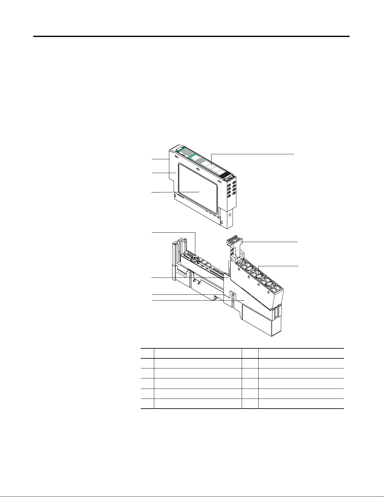
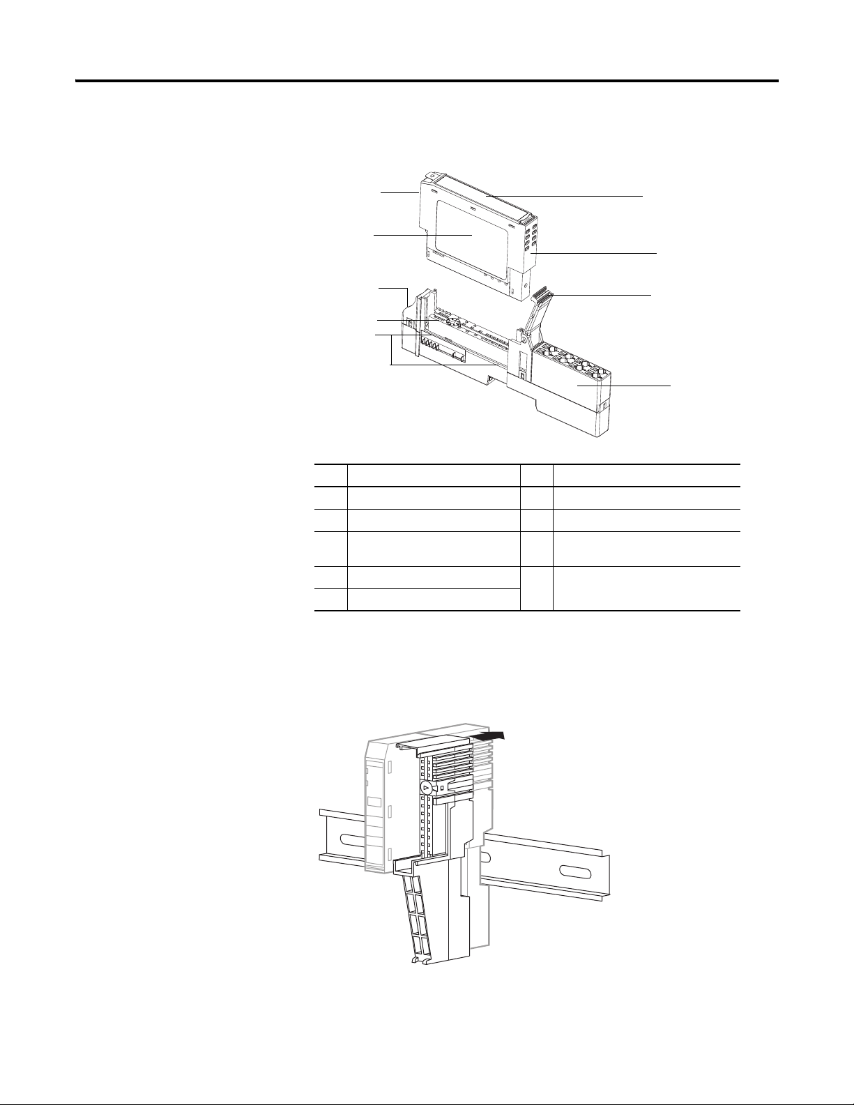
Install the Mounting Base Assembly
The 1734-TB, 1734-TBS, 1734-TB3, or 1734-TB3S wiring base assembly
consists of a 1734-MB mounting base and a 1734-RTB or 1734-RTBS removable
terminal block.
An alternative is the 1734-TOP, 1734-TOPS, 1734-TOP3, or 1734-TOP3S
POINT I/O one-piece terminal base.
Refer to the figures that show these wiring bases.
To install the mounting base assembly on the DIN rail, proceed as follows.
Description Description
1 Module Locking Mechanism 2 Slide-in Writable Label
3 RTB Removing Handle 4 Removable Terminal Block (RTB)
5 Mounting Base 6 Interlocking Side Pieces
7 DIN Rail Locking Screw (orange) 8 Mechanical Keying (orange)
9 Module Wiring Diagram 10 Insertable I/O Module
Rockwell Automation Publication 1734-UM001E-EN-P - July 2013
Page 26
10 Install POINT I/O Modules
46116
5
3
1
2
8
9
7
4
6
46117
Description Description
1 Module Locking Mechanism 2 Slide-in Writable Label
3 Insertable I/O Module 4 Handle
5 One-piece Terminal Base with
Screw or Spring Clamp
7 Mechanical Keying (orange) 8 DIN Rail Locking Screw (orange)
9 Module Wiring Diagram
6 Interlocking Side Pieces
1. Position the mounting base (wiring base assembly) vertically above the
installed units (adapter, power supply, or existing module).
2. Slide the mounting base down, allowing the interlocking side pieces to
engage the adjacent module, power supply, or adapter.
3. Press firmly to seat the mounting base on the DIN rail.
Rockwell Automation Publication 1734-UM001E-EN-P - July 2013
Page 27
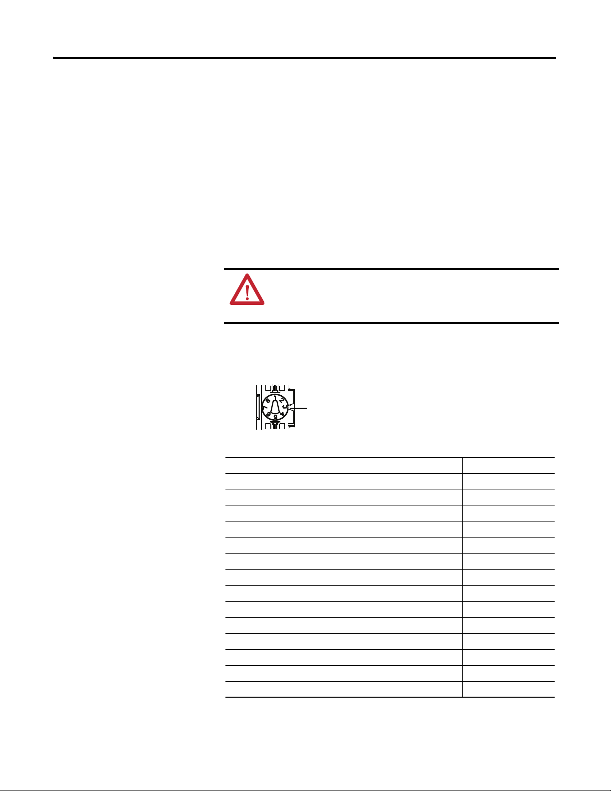
Install POINT I/O Modules 11
Notch Position 3 is shown
46148
The mounting base snaps into place.
4. To remove the mounting base from the DIN rail, remove any installed
module (and any module immediately to the right), and use a small-bladed
screwdriver to rotate the DIN-rail locking screw to a vertical position and
release the locking mechanism.
5. Lift straight up to remove the mounting base.
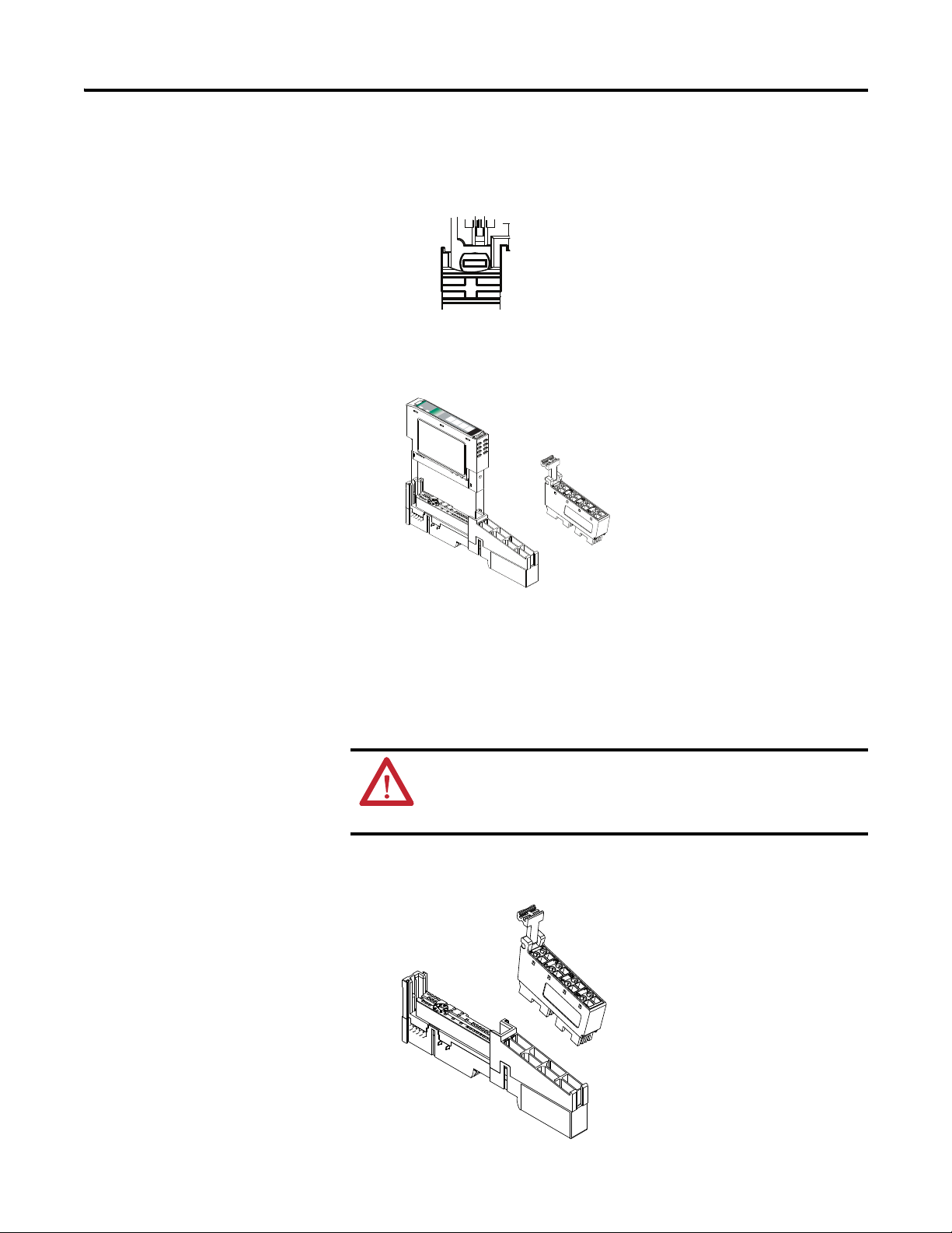
Install an I/O Module
Install the module before or after base installation. Make sure that the mounting
base is correctly keyed before installing the module into the mounting base. In
addition, make sure the mounting base locking screw is positioned horizontal
referenced to the base.
WARNING: When you insert or remove the module while
backplane power is on, an electrical arc can occur. This could cause
an explosion in hazardous location installations. Be sure that power
is removed or the area is nonhazardous before proceeding.
1. Using a bladed screwdriver, rotate the keyswitch on the mounting base
clockwise until the number required for the type of module aligns with the
notch in the base.
Module Keyswitch Position
1734-ARM
1734-CTM, 1734-VTM 5
1734-IA2, 1734-IA4 8
1734-IB2,1734-IB4, 1734-IB8 1
1734-IE2C, 1734-IE2V 3
1734-IM2, 1734-IM4 8
1734-IV2, 1734-IV4, 1734-IV8 1
1734-OA2, 1734-OA4 8
1734-OB2, 1734-OB4, 1734-OB8, 1734-OB2E, 1734-OB4E, 1734-OB8E 1
1734-OB2EP 1
1734-OE2C, 1734-OE2V 4
1734-OV2E, 1734-OV4E, 1734-OV8E 1
1734-OW2, 1734-OW4 7
1734-OX2 7
(1)
–
(1) Use the same keyswitch position as the removed module.
Rockwell Automation Publication 1734-UM001E-EN-P - July 2013
Page 28
12 Install POINT I/O Modules
46149
46150
2. Make certain the DIN-rail locking screw is in the horizontal position,
noting that you cannot insert the module if the locking mechanism is
unlocked.
3. Insert the module straight down into the mounting base and press to
secure, locking the module into place.
dule
Mo
k
Status
or
Netw
Status
NODE:
C
D
t
rce
u
u
24V
So
Outp
0
1
2
4
3
3
17
OB4E
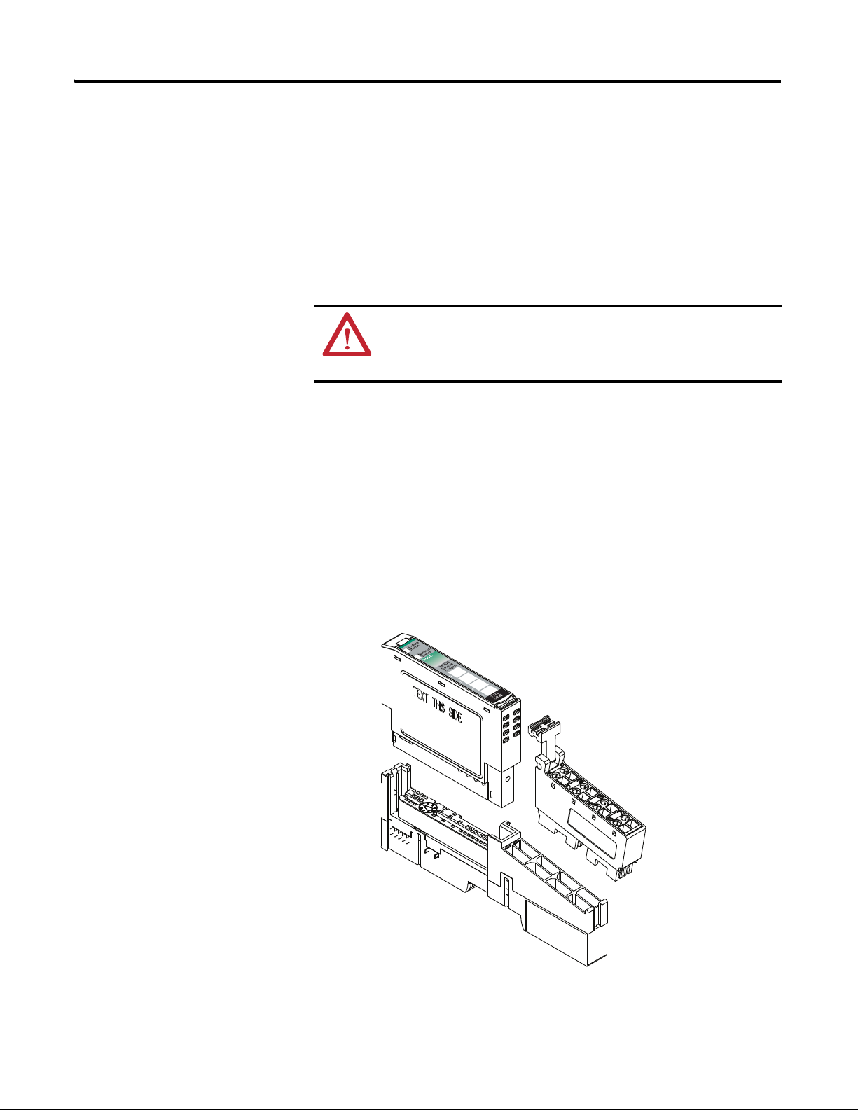
Install the Removable Terminal Block
A removable terminal block is supplied with your mounting base assembly. To
remove, pull up on the removable terminal block (RTB) handle. This lets you
remove and replace the base as necessary without removing any of the wiring. To
reinsert the removable terminal block, proceed as follows.
WARNING: When you connect or disconnect the RTB with field-side
power applied, an electrical arc can occur. This could cause an explosion
in hazardous location installations. Be sure to remove power or that the
area is nonhazardous before proceeding.
1. Insert the RTB end opposite the handle into the base unit.
This end has a curved section that engages with the mounting base.
Rockwell Automation Publication 1734-UM001E-EN-P - July 2013
Page 29
Install POINT I/O Modules 13
30880
2. Rotate the terminal block into the mounting base until it locks itself in
place.
3. If an I/O module is installed, snap the RTB handle into place on the
module.
Remove a Mounting Base
To remove a mounting base, you must remove any installed module, and remove
the removable terminal block (RTB), if wired.
WARNING: When you insert or remove the module while backplane
power is on, an electrical arc can occur. This could cause an explosion in
hazardous location installations. Be sure to remove power or that the
area is nonhazardous before proceeding.
1. Unlatch the RTB handle on the I/O module.
2. Pull on the RTB handle to remove the RTB.
3. Press in on the module lock on the top of the module, and pull up on the
I/O module to remove it from the base.
4. Remove the module to the right of the base you are removing, noting that
the interlocking portion of the base sits under the adjacent module.
5. Use a small-bladed screwdriver to rotate the orange DIN-rail locking screw
on the mounting base to a vertical position, noting that this releases the
locking mechanism.
6. Lift the mounting base straight up to remove.
Rockwell Automation Publication 1734-UM001E-EN-P - July 2013
Page 30
14 Install POINT I/O Modules
24VDC
Sink
Input
Module
Status
Network
Status
1734
IB2
NODE:
0
1
24VDC
Sink
Input
Module
Status
Network
Status
1734
IB4
NODE:
0
1
2
3
Status of Input 0
Status of Input 1
Input 0
NC
C
V
Input 1
NC
C
V
Input = 0 and 1
NC = No Connection (2 and 3)
C = Common (4 and 5)
V = Supply (6 and 7)
Input 0
C
V
Input 1
C
V
Input 2 Input 3
Status of Input 2
Status of Input 3
Input = 0, 1, 2 and 3
C = Common (4 and 5)
V = Supply (6 and 7)
1734-IB2
1734-IB4 1734-IB8
Input 0
Input 1
Input 2 Input 3
Input 4
Input 5
Input 6 Input 7
Input = 0, 1, 2, 3, 4, 5, 6 and 7
V and C are daisychained from either the adapter,
1734-FPD module, 1734-EP24DC power supply, or a
user-supplied auxiliary terminal block.
Status of Input 0
Status of Input 1
Status - Input 0 & 4
Status - Input 1 & 5
Status - Input 2 & 6
Status - Input 3 & 7
Prox
In 0 In 1
NC
C
VV
C
NC
Prox
V = 12/24V DC
C = Common
3-wire
Sink Input
2-wire
3
5
7
01
2
4
6
Wiring Digital Modules
Refer to this section to wire digital modules.
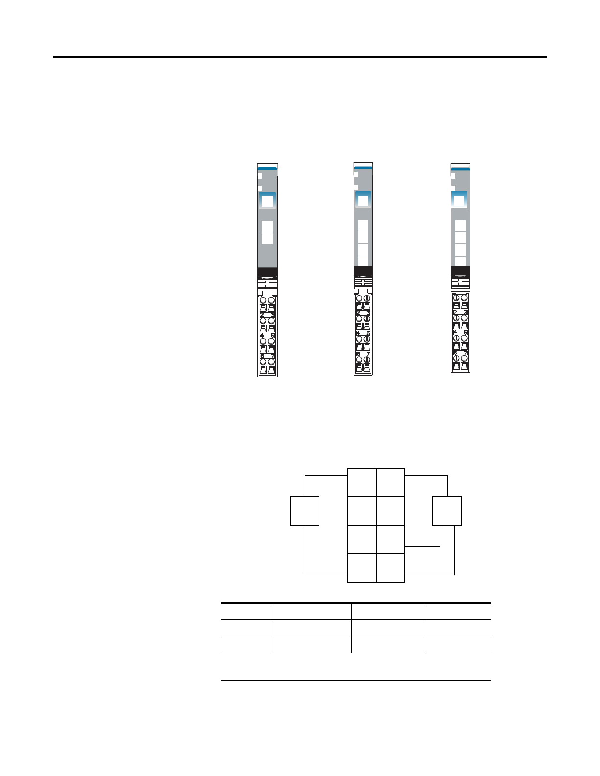
1734-IB2, 1734-IB4, and 1734-IB8 Sink Input Modules
Module
Status
Network
Status
NODE:
24VDC
Sink
Input
0
4
1
5
2
6
3
7
1734
IB8
1734-IB2 Module Wiring Diagram
Channel Input Common Voltage
00 4 6
Rockwell Automation Publication 1734-UM001E-EN-P - July 2013
11 5 7
Connect common on 3-wire proximity switches. 12/24V DC is supplied
through the internal power bus.
Page 31

Install POINT I/O Modules 15
Prox
In 0 In 1
In 2
C
VV
C
In 3
Prox ProxProx
V = 12/24V DC
C = Common
Sink Input
3
5
7
01
2
4
6
3-wire2-wire
Prox
In 0
In 1
In 2
In 4
In 6
In 7
In 5
In 3
Prox
Prox
Prox
Sink Input
3
5
7
01
2
4
6
C
V
Prox
Prox
Prox
C
V
V = 12/24V DC
C = Common
3-wire
3-wire
3-wire 3-wire
2-wire
2-wire
2-wire 2-wire
Prox
1734-IB4 Module Wiring Diagram
Channel Input Common Voltage
00 4 6
11 5 7
22 4 6
33 5 7
Connect common on 3- proximity switches. 12/24V DC is supplied
through the internal power bus.
1734-IB8 Module Wiring Diagram
Channel Input Channel Input
0044
1155
Rockwell Automation Publication 1734-UM001E-EN-P - July 2013
Page 32

16 Install POINT I/O Modules
Terminal Block with Bus Connector Strip
Channel Input Channel Input
2266
3377
Daisychain common and power connections from 1734 adapter,
1734-FPD module, 1734-EP24DC power supply, or from a usersupplied external auxiliary terminal block.
ATTENTION: When connecting more than one wire in a termination
point, make sure that both wires are the same gauge and type.
Example of Wiring - 1734-IB8 Module Using 2-Wire Proximity Switches
Module
Module
Status
Status
Network
Network
Status
DeviceNet
Status
24V dc Return
24V dc
System
Power
DeviceNet
Power
0
4
0
4
1
5
1
5
2
6
2
6
3
7
3
7
1734
1734
IB8
OB8E
Prox
Terminal Block with Bus connector strip
Prox
Prox
Prox
Prox
Prox
Prox
Prox
Rockwell Automation Publication 1734-UM001E-EN-P - July 2013
Page 33

Install POINT I/O Modules 17
In 0
In 1
In 2
In 3
In 4
In 5
In 6 In 7
0
2
3
4
5
6
7
0
1
2
3
4
5
6
7
0
1
2
3
4
5
6
7
V
V
V
V
V
VV
V
C
C
C
C
C
C
CC
1734-IB8
1734-VTM
1734-CTM
Prox
Prox
1
1734-IB8
V = Voltage Out
C = Common
Terminal Block with Bus Connector Strip
Example of Wiring - 1734-IB8 Module Using 3-wire Proximity Switches
Example of Wiring - 1734-IB8 Module Using 3-wire Proximity Switches
Module
Module
Status
Status
Network
Network
Status
DeviceNet
Status
0
4
4
1
5
5
2
6
6
3
7
7
1734
IB8
Prox
Prox
Prox
Prox
Prox
Prox
Prox
Prox
System
Power
DeviceNet
Power
0
1
2
3
1734
OB8E
24V dc Return
24V dc
Terminal Block with bus connector strip
Terminal Block with bus connector strip
Rockwell Automation Publication 1734-UM001E-EN-P - July 2013
Page 34

18 Install POINT I/O Modules
46118
Input 0 SSV 0
Input 1 SSV 1
Input 2 SSV 2
Input 3 SSV 3
Note that voltage and current are
daisychained from either the
adapter, 1734-FPD module, or
1734-EP24DC module.
Common connections for threewire devices require an external
wiring connection. A 1734-CTM
module can provide the common
connection.
Module Status
Network Status
Status of Input 0
Status of Input 1
Status of Input 2
Status of Input 3
In 0
V 0
Sink Input
3
5
7
0
1
2
4
6
Prox
Prox
Prox
Prox
In 2
In 3
In 1 V 1
V 2
V 3
V=10/28.8V DC
If a common connection is required (three-wire devices), then a 1734-CTM common terminal module
can be required.
1734-IB4D Modules
1734-IB4D Module Wiring Diagram
Rockwell Automation Publication 1734-UM001E-EN-P - July 2013
Channel Terminal Number
0 0 External
12
24
36
Connect common on three-wire proximity switches. 10/28.8V DC is supplied through the internal
power bus.
(1) Common connections require an external connection, such as a 1734-CTM module.
Input Common
(1)
Page 35

Install POINT I/O Modules 19
24VDC
Source
Input
Module
Status
Network
Status
1734
IV2
NODE:
0
1
24VDC
Source
Input
Module
Status
Network
Status
1734
IV4
NODE:
0
1
2
3
NC
C
V
Input 1
NC
C
V
Input = 0 and 1
NC = No Connection (2 and 3)
C = Common (4 and 5)
V = Supply (6 and 7)
Input = 0, 1, 2 and 3
C = Common (4 and 5)
V = Supply (6 and 7)
1734-IV2
1734-IV4
24VDC
Source
Input
Module
Status
Network
Status
1734
IV8
NODE:
0
1
2
3
4
5
6
7
Input 0
Input 2
C
V
Input 1
Input 3
C
V
Input 0
Input 2
Input 1
Input 3
Input 0
Input 6
Input 5
Input 7
Input 4
Input = 0, 1, 2, 3, 4, 5, 6 and 7
V and C are daisychained from either the
adapter, 1734-FPD module, 1734-EP24DC
power supply, or from a user-supplied auxiliary
terminal block.
1734-IV8
Module Status
Network Status
Status of Input 0
Status of Input 1
Module Status
Network Status
Status of Input 0
Status of Input 1
Status of Input 2
Status of Input 3
Module Status
Network Status
Status of Input 0 and 4
Status of Input 1 and 5
Status of Input 2 and 6
Status of Input 3 and 7
41974
Prox
In 0 In 1
NC
C
VV
C
NC
Prox
Source Input
V = 12/24V DC,
C = Common
2-wire
3-wire
3
5
7
01
2
4
6
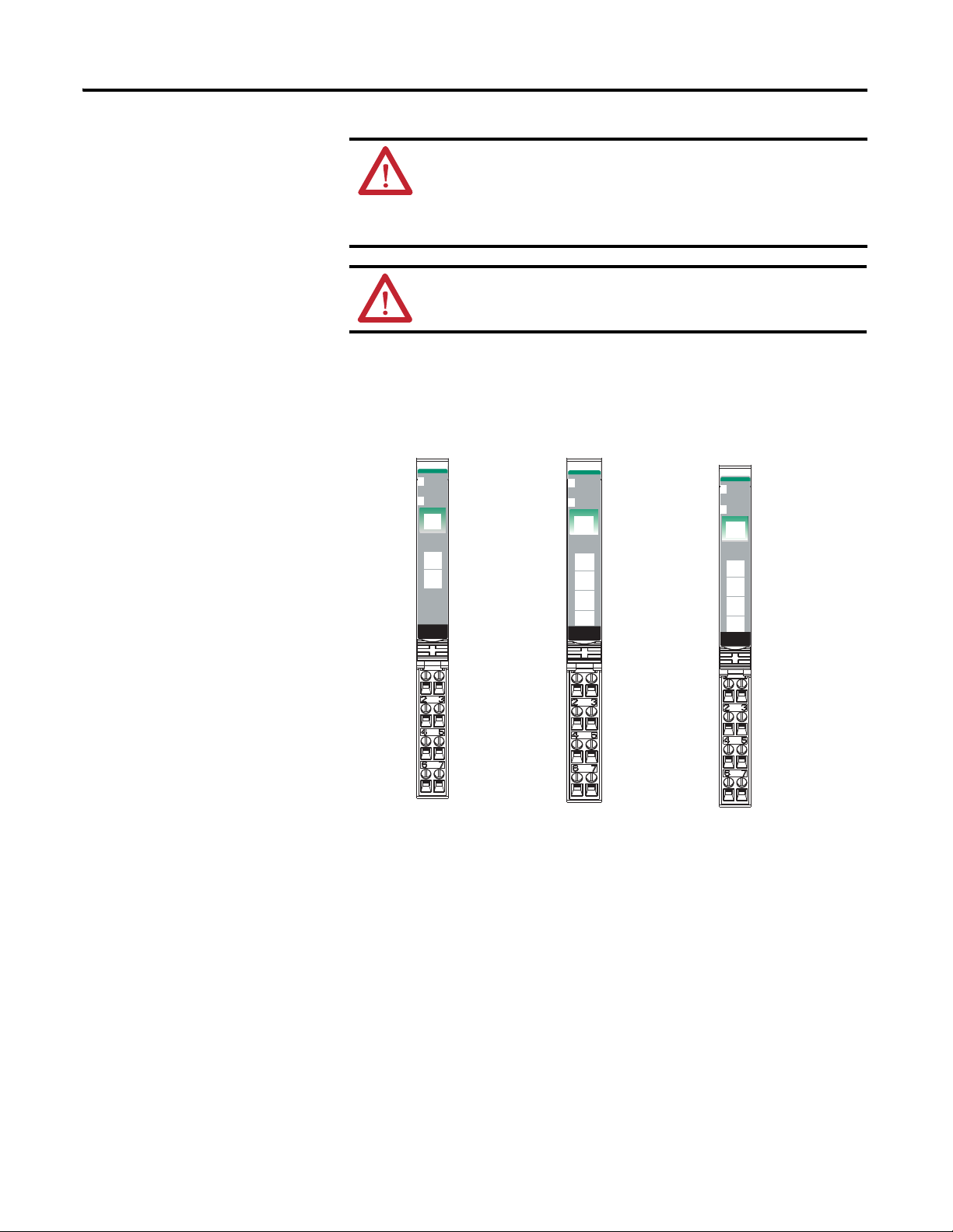
1734-IV2, 1734-IV4, and 1734-IV8 Source Input Modules
1734-IV2 Module Wiring Diagram
Channel Input Terminal Common
Channel 0 0 4 6
Channel 1 1 5 7
Connect power on 3-wire proximity switches. 12/24V DC is supplied through the
internal power bus.
Rockwell Automation Publication 1734-UM001E-EN-P - July 2013
Terminal
Power
Page 36

20 Install POINT I/O Modules
Prox
In 0 In 1
In 2
C
VV
C
In 3
Prox
Source Input
ProxProx
V = 12/24V DC
C = Common
3
5
7
0
1
2
4
6
2-wire3-wire
Source Input Wiring
In 0
In 1
In 2
In 3
In 4
In 5
In 6 In 7
0
2
3
4
5
6
7
0
1
2
3
4
5
6
7
0
1
2
3
4
5
6
7
C
C
C
C
C
CC
C
V
V
V
V
V
V
VV
1734-IB8
1734-CTM
1734-VTM
Prox
Prox
1
1734-IB8
V = Voltage Out
C = Common
3-wire
2-wire
1734-IV4 Module Wiring Diagram
Channel Input Terminal Common Terminal Power
Channel 0 0 4 6
Channel 1 1 5 7
Channel 2 2 4 6
Channel 3 3 5 7
Connect power on 3-wire proximity switches. 12/24V DC is supplied through the internal
power bus.
Rockwell Automation Publication 1734-UM001E-EN-P - July 2013
1734-IV8 Module Wiring Diagram
Channel Input Terminal Channel Input Terminal
Channel 0 0 Channel 4 4
Channel 1 1 Channel 5 5
Channel 2 2 Channel 6 6
Channel 3 3 Channel 7 7
Daisychain common and power connections from 1734 Adapter, 1734-FPD, 1734-EP24DC
or from user supplied external auxiliary terminal block.
Page 37
Install POINT I/O Modules 21
24VDC
Source
Output
Module
Status
Network
Status
1734
OB8E
0
1
2
3
NODE:
4
5
6
7
42016
Module Status
Network Status
Status of Output 0
Status of Output 1
Status of Output 3
Output 0
Output 0
C
C
Output 1
Output 1
C
C
24VDC
Source
Output
Module
Status
Network
Status
1734
OB2E
NODE:
0
1
Output 0
Output 2
Output 1
Output 3
C
C
V
V
C = Common
V = Supply
1734-OB2E
1734-OB4E
Output 0
Output 2
Output 1
Output 3
Output 4
Output 6
Output 5
Output 7
1734-OB8E
Status of Output 0 & 4
Status of Output 1 & 5
Status of Output 2 & 6
Status of Output 3 & 7
Status of Output 2
Status of Output 0
Status of Output 1
WARNING: When you connect or disconnect wiring while field side
power is on, an electrical arc can occur. This could cause an explosion in
hazardous location installations.
Be sure that power is removed or the area is nonhazardous before
proceeding.
ATT ENTI ON: When connecting more than one wire in a termination
point, make sure that both wires are the same gauge and type.
1734-OB2E, 1734-OB4E, 1734-OB8E, 1734-OB2, 1734-OB4, and 1734-OB8 Protected Output Modules
Module
Status
Network
Status
NODE:
24VDC
Source
Output
0
1
2
3
1734
OB4E
Rockwell Automation Publication 1734-UM001E-EN-P - July 2013
Page 38

22 Install POINT I/O Modules
24VDC
Source
Output
Module
Status
Network
Status
1734
OB8
0
1
2
3
NODE:
4
5
6
7
42016
Status of Output 0
Status of Output 1
Status of Output 2
Status of Output 3
Output 0
Output 0
C
C
Output 1
Output 1
C
C
Output 0
Output 2
Output 1
Output 3
C
C
V
V
C = Common
V = Supply
1734-OB2
1734-OB4
Output 0
Output 2
Output 1
Output 3
Output 4
Output 6
Output 5
Output 7
1734-OB8
Status of Output 0 & 4
Status of Output 1 & 5
Status of Output 2 & 6
Status of Output 3 & 7
Module Status
Network Status
Status of Output 0
Status of Output 1
Out 0
Out 1
Out 1
Out 0
CC
V
V
44338
0
2
6
4
3
5
7
1
V = 12/24V DC, C = Common
Field power is supplied from internal power bus
Load
Load
Module
Status
Network
Status
NODE:
24VDC
Source
Output
0
1
1734
OB2
Module
Status
Network
Status
NODE:
24VDC
Source
Output
0
1
2
3
1734
OB4
1734-OB2 and 1734-OB2E Module Wiring Diagram
Rockwell Automation Publication 1734-UM001E-EN-P - July 2013
Channel Output
Channel 0 0, 2 4 6
Terminal
Common
Terminal
Channel 1 1, 3 5 7
Module power is supplied from the internal power bus.
Power
Page 39

Install POINT I/O Modules 23
44339
V = 12/24V DC,
C = Common
Field power is supplied from internal power bus
Out 0
Out 1
Out 3
Out 2
CC
C
C
0
2
6
4
3
5
7
1
Load
Load
Load
Load
1734-OB4 and 1734-OB4E Module Wiring Diagram
Channel Output
Terminal
Common
Terminal
Channel 0 0 6
Channel 1 1 7
Channel 2 2 4
Channel 3 3 5
Module power is supplied from internal power bus.
Power
Rockwell Automation Publication 1734-UM001E-EN-P - July 2013
Page 40

24 Install POINT I/O Modules
Out 0
Out 1
Out 3
Out 2
Load
Load
Common must be daisychained from a 1734 adapter, 1734-FPD module, 1734-EP24DC
power supply, or from a user-supplied auxiliary terminal block. The 24V DC power to the
module is supplied by the internal power bus and comes from the same 1734 adapter,
1734-FPD module, or 1734-EP24DC power supply as common.
2
6
3
7
4
5
Load
Out 4
Out 5
C
Load
Load
Load
C
Load
Load
Out 6
Out 7
0
1
1734-CTM
1734-OB8, 1734-OB8E
Load
Load
Load
Load
Out 7
Out 0
Out 1
Out 2
Out 3
Out 4
Out 5
Out 6
C
CC
C
C
C
C
C
5
1
3
7
0
4
5
6
2
1
3
7
0
4
6
2
1734-OB8 and 1734-OB8E Module Wiring Diagram
Channel
Output Terminal Common Terminal Power
Number
Channel 0 0 Common is
Channel 1 1
Channel 2 2
Channel 3 3
Channel 4 4
Channel 5 5
Channel 6 6
Channel 7 7
Module power is supplied from the internal power bus.
daisychained from
either a 1734 adapter,
1734-FPD module,
1734-EP24DC power
supply, or from a usersupplied external
terminal block.
The 24V DC power for
the module is supplied
by the internal power
bus and originates
from the same adapter,
1734-FPD module, or
1734-EP24DC power
supply as common.
Rockwell Automation Publication 1734-UM001E-EN-P - July 2013
Page 41

1734-OB2EP Protected Output Module
Protected
Sourcing
Output
Module
Status
Network
Status
1734
OB2EP
NODE:
0
1
42016
Module Status
Network Status
Status of Output 0
Status of Output 1
Output 0
Connection
Output 0
Connection
Output 1
Connection
Output 1
Connection
C
C
V
V
C = Common
V = Supply
V = 12/24V DC, C = Common
Field power is supplied from internal power
bus
Out 0
Out 1
Out 1
Out 0
CC
V
V
0
2
6
4
3
5
7
1
Load
Load
Install POINT I/O Modules 25
1734-OB2EP DC Protected Output Module Wiring Diagram
Channel Output
Term in al
Channel 0 0, 2 4 6
Channel 1 1, 3 5 7
Module power is supplied from the internal power bus.
Common
Terminal
Power
Rockwell Automation Publication 1734-UM001E-EN-P - July 2013
Page 42

26 Install POINT I/O Modules
Relay
Output
Module
Status
Network
Status
1734
OW2
NODE:
0
1
41974
Module Status
Network Status
Status of Output 0
Status of Output 1
C
V
C
V
C = Common
V = Supply
Output 0A
Output 0B
Output 1A
Output 1B
Output 0A
Output 0B
Output 1A
Output 1B
Output 2A
Output 2B
Output 3A
Output 3B
1734-OW41734-OW2
Status of Output 0
Status of Output 1
Status of Output 2
Status of Output 3
Module Status
Network Status
C
C
V
V
Out = Output channel relay contacts
V = Supply (can range from +5V DC…240V AC)
C = Common
Out 0A
Out 0B
Out 1A
Out 1B
Load
Load
0
2
4
6
3
5
7
1
1734-OW2 and 1734-OW4 Relay Output Modules
Module
Status
Network
Status
NODE:
Relay
Output
0
1
2
3
1734
OW4
ATTENTION: Relay contacts are not powered by the internal power bus.
Load power can be provided by the internal power bus or an external
power source.
1734-OW2 Modules with Load Powered by Internal Power Bus Wiring Diagram
Channel Output Common Supply
0A 0 4 6
0B 2 4 6
1A 1 5 7
1B 3 5 7
Supply voltage can range from +5V DC…240V AC, depending on relay load.
Power for the module can be provided by the internal power bus.
Rockwell Automation Publication 1734-UM001E-EN-P - July 2013
Page 43

Install POINT I/O Modules 27
C
C
V
V
Out 0A
Out 0B
Out 1A
Out 1B
Load
Power
Supply
Out = Output channel relay contacts
Power Supply = can range from +5V DC…240V AC
C = Common
0
2
4
6
3
5
7
1
Power
Supply
Load
Out 2A
Out 3A
Out 3B
Out 2B
Out 0A
Out 0B
Out 1A
Out 1B
Load
Power
Supply
Out = Output channel relay contacts
0
2
4
6
3
5
7
1
Power
Supply
Load
Power
Supply
Load
Load
Power
Supply
1734-OW2 Modules with Load Powered by External Power Wiring Diagram
Channel Output Common
Supply
(1)
0A 0 Not used Not used
0B 2 Not used Not used
1A 1 Not used Not used
1B 3 Not used Not used
(1) Supply voltage can range from +5V DC…240V AC, depending on relay load. Power for
the module can be provided by the external power supply.
1734-OW4 Modules with Load Powered by External Power Wiring Diagram
Channel Output Common
0A 0
0B 2
1A 1
Rockwell Automation Publication 1734-UM001E-EN-P - July 2013
Supply
(1)
Page 44

28 Install POINT I/O Modules
01 01 01
120V AC
PDN OW2OW2
AC Power Bus
Channel Output Common
Supply
1B 3
2A 4
2B 6
3A 5
3B 7
(1) Supply voltage can range from +5V DC… 240V AC, depending on relay load.
12/24V DC power for the module is provided by the external power supply.
The power supply voltage may be daisychained from a 1734 adapter, 1734-FPD module,
or 1734-EP24DC power supply communication interface. Each channel is individually
isolated and may have a unique supply or voltage as necessary.
ATTENTION: Do not attempt to increase load current or wattage
capability beyond the maximum rating by connecting two or more
outputs in parallel. The slightest variation in relay switching time may
cause one relay to momentarily switch the total load current.
Make certain that all relay wiring is properly connected before applying any
power to the module.
Total current draw through the wiring base unit is limited to 10 A. Separate
power connections to the terminal base unit may be necessary.
Use the end cap from your adapter or interface module to cover the exposed
interconnections on the last mounting base on the DIN rail. Failure to do so
could result in equipment damage or injury from electric shock.
(1)
Relay Modules Using AC Only
Rockwell Automation Publication 1734-UM001E-EN-P - July 2013
Page 45

Install POINT I/O Modules 29
AC
Power
Bus
DC
Power
Bus
C V 120V AC
PDN IB2 IV2 IB4 IV4 FPD OW2 OW2 OW2
AC
Power
Bus
DC
Power
Bus
C V 120V AC
PDN IB2 IV2 IB4 IV4 EPAC OW2 OW2 OW2
01 01 01 01 01 0101 01
24V
L1
120V AC/240V AC
42010
L2/N
PDN IB2 IB4 IV2 IV4
OW2
OW2
OW2
DC Power
Bus
DC Power
Bus
Relay Modules Using a 1734-FPD or 1734-EPAC Module to Create a New AC Power Bus
Relay Modules Using External Wiring for AC Power
Rockwell Automation Publication 1734-UM001E-EN-P - July 2013
Page 46

30 Install POINT I/O Modules
24VDC
Sink
Output
Module
Status
Network
Status
1734
OV4E
NODE:
0
1
2
3
2
Module Status
Network Status
Status of Output 1
Status of Output 0
Status of Output 0 & 4
Status of Output 1 & 5
Status of Output 2 & 6
Status of Output 3 & 7
Output 1
Output 1
Output 3
V
Output 1
Output 5
Output 3
Output 7
Output 4
Output 6
Output 2
Output 0
Output 0
Output 2
V
V
V
C
N/C
Output 0
C
N/C
V
V
46120
46121 46122
C = Common
V = Supply
1734-OV2E
1734-OV4E
1734-OV8E
Status of Output 0 & 4
Status of Output 1 & 5
Status of Output 2 & 6
Status of Output 3 & 7
Module Status
Network Status
Module Status
Network Status
Out 0
Out 1
NC
NC
C
C
V
V
Load
Load
V = 12/24V DC, C = Common
Field power is supplied from internal power bus
0
2
6
4
3
5
7
1
1734-OV2E, 1734-OV4E, and 1734-OV8E Sink Output Modules
0
1
NODE:
Module
Status
Network
Status
24VDC
Sink
Output
1734
OV2E
NODE:
0
1
2
3
Module
Status
Network
Status
24VDC
Sink
Output
1734
OV8E
4
5
6
7
DC Sink Output Module Cat. No. 1734-OV2E Wiring Diagram
Rockwell Automation Publication 1734-UM001E-EN-P - July 2013
Channel Output Terminal Power Common
Terminal
Channel 0 0 6 4
Channel 1 1 7 5
Module power is supplied from the internal power bus.
Page 47

Install POINT I/O Modules 31
Out 0 Out 1
Out 3Out 2
V
V
V
V
Load
Load
Load
Load
V = 12/24V DC, C = Common
Field power is supplied from internal power bus
0
2
6
3
1
7
45
1734-OV8E
Load
Load
Load
Load
Out 7
Out 0
Out 1
Out 2
Out 3
Out 4
Out 5
Out 6
V = Voltage Out
5
1
3
7
0
4
5
6
2
1
3
7
0
4
6
2
1734-VTM
V
VV
V
V
V
V
V
DC Sink Output Module Cat. No. 1734-OV4E Wiring Diagram
Channel Output Terminal Power Common Terminal
Channel 0 0 6
Channel 1 1 7
Channel 2 2 4
Channel 3 3 5
Module power is supplied from internal power bus.
DC Sink Output Module Cat. No. 1734-OV8E Wiring Diagram
Rockwell Automation Publication 1734-UM001E-EN-P - July 2013
Page 48

32 Install POINT I/O Modules
Relay
Output
Module
Status
Network
Status
1734
OX2
NODE:
0
1
01
2
3
4
5
6
7
41974
Module Status
Network Status
Status of Output 0
Status of Output 1
Output 0 Relay Common - RC
+V
RC - Output 1 Relay Common
+V
Output 0 Connection - NC
Output 0 Connection - NO
NC - Output 1 Connection
NO - Output 1 Connection
NC = Normally closed
NO = Normally open
RC = Relay Common
+V = Positive Supply
+V
+V
Out 0
NC
Out 1
NC
Load
Load
0
2
4
6
3
5
7
1
L1
L1
NC = Normally closed
NO = Normally open
RC = Relay Common
+V = Positive Supply
L2/N
L2/N
Out 0
NO
Out 1
NO
Out 0
RC
Out 1
RC
1734-OX2 2-relay Output Modules
Rockwell Automation Publication 1734-UM001E-EN-P - July 2013
ATTENTION: Relay contacts are not powered by the internal power bus.
Load power can be provided by the internal power bus or an external
power source.
1734-OX2 Module with Load Powered by Internal Power Bus Wiring Diagram
Channel Output Relay Common Supply
0 (N.C.) 0 4 6
0 (N.O.) 2
1 (N.C.) 1 5 7
1 (N.O.) 3
Supply voltage can range from +5V DC…240V AC, depending on relay load.
12V, 24V DC, 120V, 240V AC power for the module is provided by the internal power bus.
Page 49
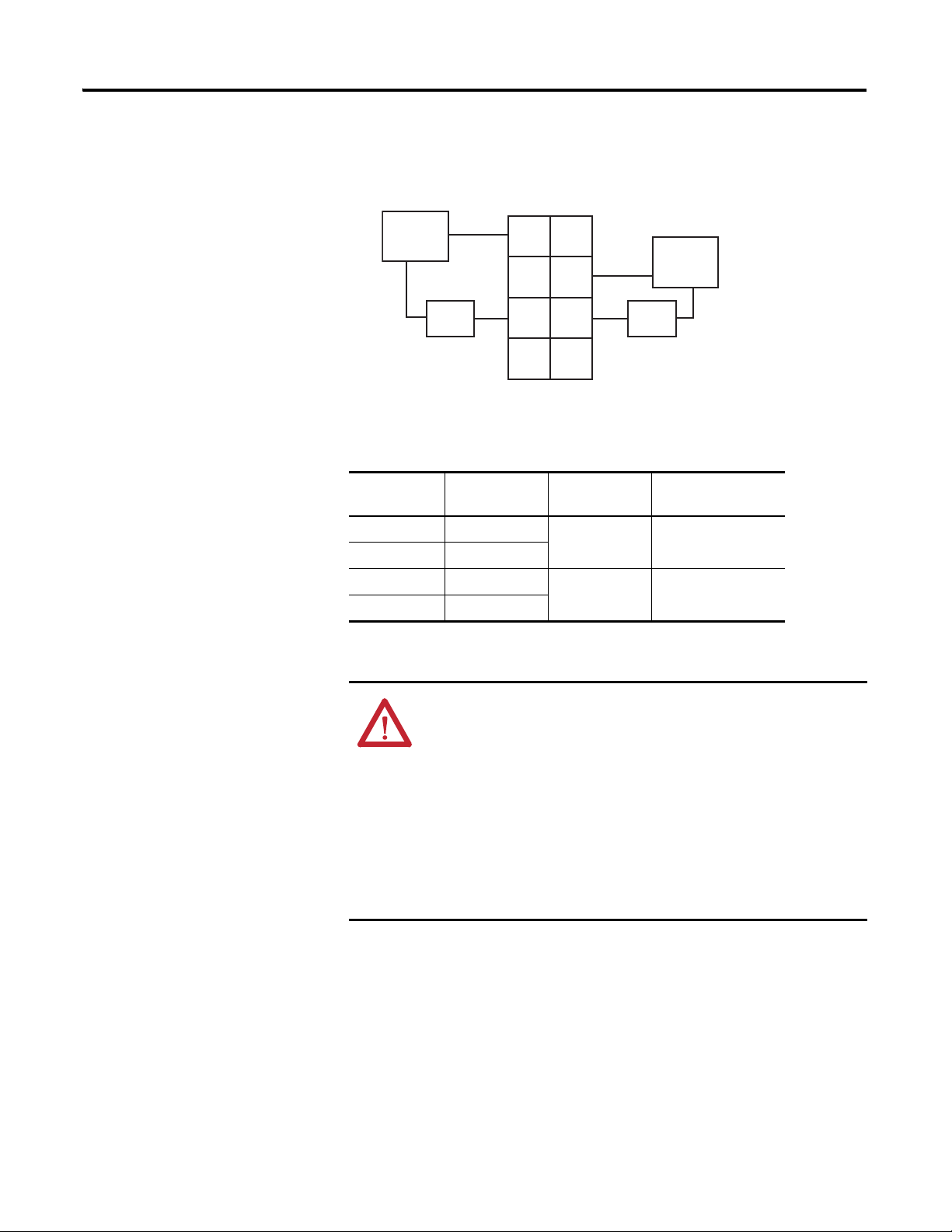
Install POINT I/O Modules 33
+V
+V
Out 0
NC
Out 1
NC
Out 1
NO
Load
Power
Out = Output channel relay contacts
Power Supply = can range from +5V DC…240V AC
RC = Relay Common
0
2
4
6
3
5
7
1
Power
Supply
Load
L1
L2/N
L1
L2/N
Out 1
RC
Out 0
RC
Out 0
NO
1734-OX2 Modules with Load Powered by External Power Bus Wiring Diagram
Channel Output Relay
Supply
(1)
Common
0 (N.C.) 0 4 6
0 (N.O.) 2
1 (N.C.) 1 5 7
1 (N.O.) 3
(1) Supply voltage can range from +5V DC…240V AC, depending on relay load. 12V, 24V DC,
120V, 240V AC power for the module is provided by the internal power bus
ATT ENTI ON: Do not attempt to increase load current or wattage
capability beyond the maximum rating by connecting two or more
outputs in parallel. The slightest variation in relay switching time may
cause one relay to momentarily switch the total load current.
Make certain that all relay wiring is properly connected before applying any
power to the module.
Total current draw through the wiring base unit is limited to 10 A. Separate
power connections to the terminal base unit may be necessary.
Use the end cap from your adapter or interface module to cover the exposed
interconnections on the last mounting base on the DIN rail. Failure to do so
could result in equipment damage or injury from electric shock.
Rockwell Automation Publication 1734-UM001E-EN-P - July 2013
Page 50

34 Install POINT I/O Modules
01 01 01 01 01
001
01
1
01 01 01
120V AC
PDN OX2OX2
PDN IB2 IB4IV2 IV4
FPD OX2 OX2 OX2
AC Power
Bus
C
V
120V AC or 240V AC Based on I/O Modules
Wiring With AC
Modules Only
Wiring Using a 1734-FPD Module To Create a New AC
Power Bus
24V DC
42090OX
Wire with AC Modules Only using a 1734-PDN Module or
1734-PDN Module to Create a New AC Power Bus
Rockwell Automation Publication 1734-UM001E-EN-P - July 2013
Page 51

Install POINT I/O Modules 35
46124
AENT
01 01
01 01
01 01
01 01 01
01 01 01
EPAC
OX2OX2
AENT IB2 IB4IV2 IV4 FPD OX2 OX2 OX2
AENT
OX2OX2
OX2 OX2 OX2AENT IB2 IB4
IV2
IV4
24V DC
24V DC
120V AC or 240V AC Based on I/O Modules
24V DC
24V DC
120V AC or 240V AC Based on I/O Modules
CCV
V
V
V
C
C
Wire with AC Modules Only Using a 1734-AENT Module, or
Using a 1734-AENT Module to Create a New AC Power Bus
46123
01 01 01
01 01
01 01 01
01 01
01 01
Rockwell Automation Publication 1734-UM001E-EN-P - July 2013
Page 52

36 Install POINT I/O Modules
01 0101 01 01 0101 01
24V L2/N
PDN
IB2
IB4 IV2 IV4
OX2OX2
OX2
Wire Using External Power Source for AC Relay Power
120V/240V AC
L1
46125
Module Status
Network Status
Status of Input 0
Status of Input 1
Channel 0
Connection
No Connection
No Connection
L2/N
L2/N
L1
L1
L2/N = 120V AC return
L1 = 120V AC Supply
Channel 1
Connection
Module Status
Network Status
Status of Input 0
Status of Input 1
Channel 0
Connection
No Connection
No Connection
L2/N
L2/N
L1
L1
Channel 1
Connection
1734-IA2
1734-IA4
46126
Status of Input 2
Status of Input 3
1734-IA2 and 1734-IA4 120 V AC Input Modules
Module
Status
Network
Status
NODE:
Input
IA2
120VAC
0
1
1734
Module
Status
Network
Status
NODE:
120VAC
Input
0
1
2
3
1734
IA4
Rockwell Automation Publication 1734-UM001E-EN-P - July 2013
Page 53
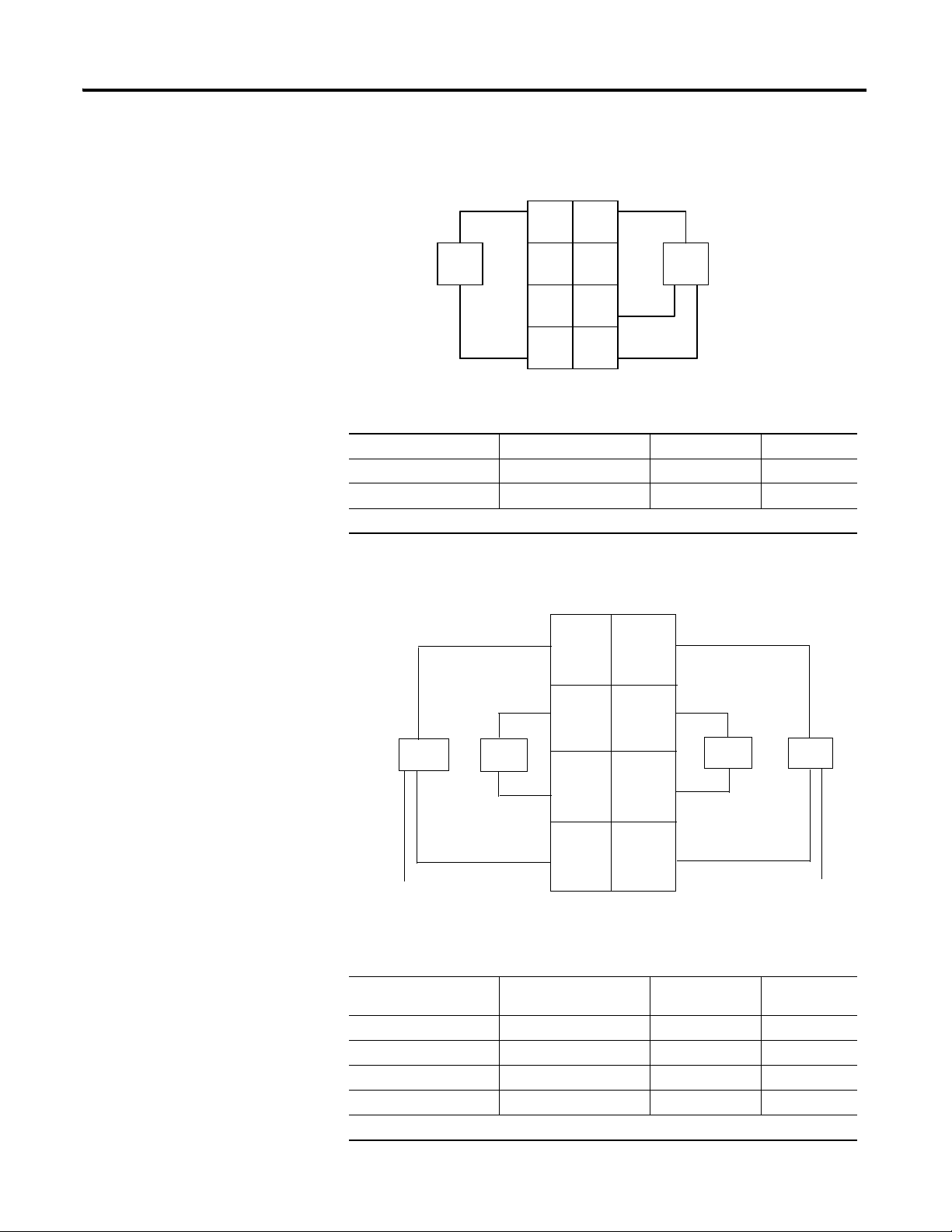
Install POINT I/O Modules 37
Prox
Ch 0 Ch 1
NC
L2/N
L1 L1
L2/N
NC
Prox
3-wire2-wire
3
5
7
01
2
4
6
Ch 0 = Channel 0 Ch 1 = Channel 1
NC = No connection L2/N = 120V AC Neutral L1 = 120V AC
Ch0 = Channel 0 Input Ch1 = Channel 1 Input Ch2 = Channel 2 Input
Ch3 = Channel 3 Input L2/N = 120V AC Neutral L1 = 120V AC
Ch 1
L 1
L 1
L 1
Ch 3
L 1
Ch 0
Ch 2
1
6
4
2
0
3
5
7
Prox
Prox
Prox
Prox
L2/N
L2/N
1734-IA2 120 V AC Input Module Wiring Diagram
Channel Input Terminal Return Supply
0046
1157
Module power is supplied from the internal power bus.
1734-IA4 120 V AC Input Module Wiring Diagram
Channel Input Terminal Common
Terminal
Power
00 4
11 5
22 6
33 7
Module power is supplied from the internal power bus.
Rockwell Automation Publication 1734-UM001E-EN-P - July 2013
Page 54

38 Install POINT I/O Modules
220VAC
Input
Module
Status
Network
Status
1734
IM4
0
1
NODE:
2
3
46134
Module Status
Network Status
Status of Input 0
Status of Input 1
Channel 0
Connection
No Connection
Channel 1
Connection
No Connection
L2/N
L2/N
L1
L1
46134
Module Status
Network Status
Status of Input 0
Status of Input 1
Channel 0
Connection
No Connection
Channel 1
Connection
No Connection
L2/N
L2/N
L1
L1
L2/N = 220V AC return
L1 = 220V AC Supply
1734-IM2
1734-IM4
Status of Input 2
Status of Input 3
1734-IM2 and 1734-IM4 220V AC Input Modules
Module
Status
Network
Status
NODE:
0
1
2
3
220VAC
Input
1734
IM4
Rockwell Automation Publication 1734-UM001E-EN-P - July 2013
Page 55

Install POINT I/O Modules 39
Prox
Ch 0
Ch 1
NC
L2/N
L1 L1
L2/N
NC
Prox
3-wire2-wire
3
5
7
01
2
4
6
41966B
Ch 0 = Channel 0 input Ch 1 = channel 1 input
NC = No connection L2/N = 220V AC Neutral
L1 = 220V AC
Ch0 = Channel 0 Input Ch1 = Channel 1 Input Ch2 = Channel 2 Input
Ch3 = Channel 3 Input L2/N = 120V AC Neutral L1 = 120V AC
Ch 1
L 1
L 1
L 1
Ch 3
L 1
Ch 0
Ch 2
1
6
4
2
0
3
5
7
Prox
Prox
Prox
Prox
L2/N
L2/N
1734-IM2 120V AC 2 Input Module Wiring Diagram
Channel Input Terminal Return Supply
0046
1157
Module power is supplied from the internal power bus.
Channel Input Terminal Common
00 4
11 5
22 6
33 7
Module power is supplied from the internal power bus.
Use an external neutral bus or a 1734-CTM module for AC (220V) neutral connections, if required.
Rockwell Automation Publication 1734-UM001E-EN-P - July 2013
Terminal
Power
Page 56

40 Install POINT I/O Modules
120/220VAC
Output
Module
Status
Network
Status
1734
OA4
0
1
2
3
NODE:
46132
Module Status
Network Status
Channel 0
Connection
No Connection
Channel 1
Connection
No Connection
L2/NL2/N
L1L1
L2/N = 120/220V AC
return
Module Status
Network Status
Status of Output 0
Status of Output 1
Channel 0
Connection
Channel 1
Connection
Channel 3
Connection
L2/N
1734-OA4
Status of Output 0
Status of Output 1
1734-OA2
Status of Output 2
Status of Output 3
Channel 2
Connection
L1/NL1/N
L2/N
46133
Ch 1
L2/N
L 1
L 1
NC
L2/N
Ch 0
NC
1
6
4
2
0
3
5
7
Load
Load
1734-OA2 AC 2 Output Module Wiring Diagram
L1 =120/220V AC supply, L2/N = 120/220V AC return
Ch 0 = Channel 0 Ch 1 = Channel 1
Field power is supplied from internal power bus
NODE:
0
1
NODE:
Module
Status
Network
Status
120VAC
Input
1734
OA2
1734-OA2 and 1734- OA4 120/220V AC Output Modules
Rockwell Automation Publication 1734-UM001E-EN-P - July 2013
Channel Output
Channel 0 0 4 6
Channel 1 1 5 7
Module power is supplied from the internal power bus.
Terminal
Return Supply
Page 57
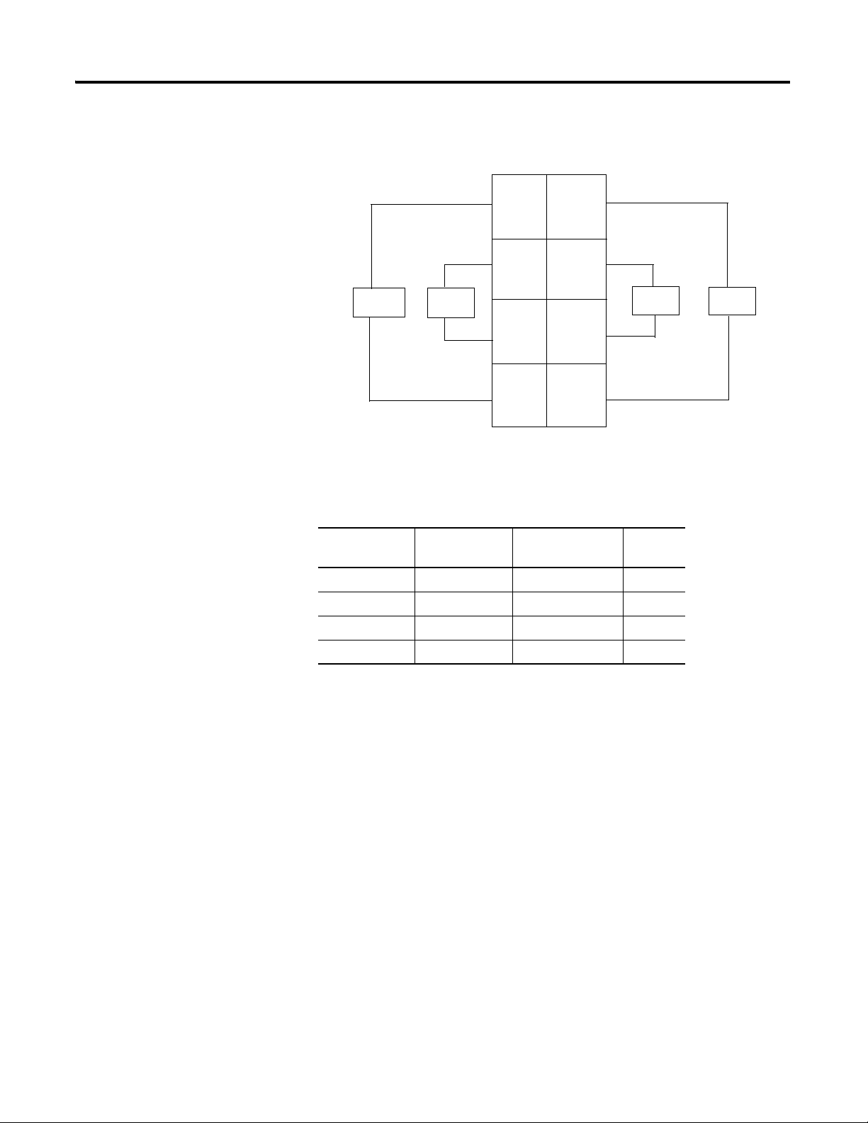
Install POINT I/O Modules 41
44399
L1 =120/220V AC Supply
L2/N = 120/220V AC Return
Ch 0 = Channel 0 Ch 2 = Channel 2
Ch 1 = Channel 1 Ch 3 = Channel 3
Field power is supplied from the internal power bus.
1734-OA4 AC 2 Output Module Wiring Diagram
Ch 1
L2/N
L2/N
L2/N
Ch 3
L2/N
Ch 0
Ch 2
1
6
4
2
0
3
5
7
Load
Load
Load
Load
Channel Output
004
115
226
337
Terminal
Common
Terminal
Power
Rockwell Automation Publication 1734-UM001E-EN-P - July 2013
Page 58

42 Install POINT I/O Modules
41974
Module Status
Network Status
Status of Input 0
Status of Input 1
Input 0 Connection
Chas Gnd
C
V
Input 1 Connection
Chas Gnd
C
V
4-20mA
Analog
Input
Module
Status
Network
Status
1734
IE2C
NODE:
0
1
Chas Gnd = Chassis ground
C = Common
V = Supply
In 0 In 1
CC
V
V
Current
Input
2-wire
In = Input channel
Chas Gnd = Chassis Ground
C = Common
V = 12/24V DC supply
5
7
0
1
2
4
6
Current
Input
Device
4-wire
AC or
DC
Chas
Gnd
Chas
Gnd
3
Wiring Analog Modules
1734-IE2C Analog Current Input Module
1734-IE2C Analog Current Input Module Wiring Diagram
Channel Current Input Chassis Ground Common Voltage
00 2 4 6
11 3 5 7
12/24V DC is provided by the internal power bus.
Rockwell Automation Publication 1734-UM001E-EN-P - July 2013
Page 59

1734-IE2V Analog Voltage Input Module
41974
Module Status
Network Status
Status of Input 0
Status of Input 1
Input 0 Connection
Chas Gnd
C
Input 1 Connection
Chas Gnd
C
Chas Gnd = Chassis ground
C = Common
V = Supply
Analog
Voltage
Input
Module
Status
Network
Status
1734
IE2V
NODE:
0
1
VV
In 0 In 1
C
C
VV
Voltage
Input
In = Input channel
Chas Gnd = Chassis Ground
C = Common
V = 12/24V DC supply
3
5
7
0
1
2
4
6
Voltage
Input
Chas
Gnd
Chas
Gnd
Install POINT I/O Modules 43
1734-IE2V Analog Voltage Input Module Wiring Diagram
Channel Voltage Input Chassis Ground Common Supply
00 2 4 6
11 3 5 7
12/24V DC is provided by the internal power bus.
Rockwell Automation Publication 1734-UM001E-EN-P - July 2013
Page 60

44 Install POINT I/O Modules
4-20mA
Analog
Output
Module
Status
Network
Status
1734
OE2C
NODE:
0
1
41974
Module Status
Network Status
Status of Output 0
Status of Output 1
Output 0 Connection
Chas Gnd
C
V
Output 1 Connection
Chas Gnd
C
V
ChasGnd = Chassis ground
C = Common
V = Supply
2-wire
Current Output
Device
Out = Output channel
Chas Gnd = Chassis ground
C = Common
V = Not used
AC or
DC
4-wire
Current Output
Device
0 1
2 3
4 5
6 7
Chas
Gnd
Chas
Gnd
C
C
V
V
Out 0
Out 1
1734-OE2C Analog Current Output Module
Rockwell Automation Publication 1734-UM001E-EN-P - July 2013
1734-OE2C Analog Current Output Module Wiring Diagram
Channel Current Output Common Chassis Ground Supply
00 42 6
11 53 7
12/24V DC power is provided by the internal power bus.
Page 61

1734-OE2V Analog Voltage Output Module
Analog
Voltage
Output
Module
Status
Network
Status
1734
OE2V
NODE:
0
1
Module Status
Network Status
Status of Output 0
Status of Output 1
Output 0 Connection
Chas Gnd
C
V
Output 1 Connection
Chas Gnd
C
V
Chas Gnd = Chassis ground
C = Common
V = Supply
41974
Out 0
Out 1
C
C
V
V
Out = Output channel
Chas Gnd = Chassis ground
C = Common
V = 12/24V Supply
42017IRR
3
5
7
0
1
2
4
6
Voltage
Output
Voltage
Output
Chas
Gnd
Chas
Gnd
Install POINT I/O Modules 45
1734-OE2V Analog Voltage Output Module Wiring Diagram
Channel Voltage Output Chassis Ground Common Supply
00 2 46
11 3 57
12/24V DC power is provided by the internal power bus.
Rockwell Automation Publication 1734-UM001E-EN-P - July 2013
Page 62

46 Install POINT I/O Modules
41970
System Power
CHAS GND
C
V
NC
CHAS GND
C
V
NC
DeviceNet Connector
DeviceNet Power
NC = No Connection
CHAS GND = Chassis Ground
C = Common
V = Supply
V DC
NC
CHAS
GND
C
V
NC
C
V
This supply will be
connected to the internal
field power bus.
12/24V DC
Power
NC = No Connection
CHAS GND = Chassis Ground
C = CommonV = Supply
CHAS
GND
3
5
7
0
1
2
4
6
DeviceNet
connection
Black
Blue
Bare
White
Red
-V
CAN - Low
Shield
CAN - High
+V
1
2
3
4
5
Wiring Power Distribution and Other Modules
1734-PDN Communication Interface Module
Rockwell Automation Publication 1734-UM001E-EN-P - July 2013
1734-PDN Module Wiring Diagram
Page 63

Install POINT I/O Modules 47
01 01 01
120V AC
PDN OW2OW2
AC Power Bus
C
V
NC
C
V
NC
NC = No Connection
CHAS GND = Chassis Ground
C = Common V = Supply
CHAS GND
CHAS GND
Wire the Communication Interface Module for AC Modules Only
1734-FPD Field Potential Distributor Module
Rockwell Automation Publication 1734-UM001E-EN-P - July 2013
Page 64

48 Install POINT I/O Modules
NC NC
C
VV
C
V DC
V = 12/24V DC, C = Common
CHAS GND = Chassis ground
This supply will be
connected to the
internal power bus.
3
5
7
01
2
4
6
CHAS
GND
CHAS
GND
L2/N
L1 L1
L2/N
V AC
L2/N = Neutral, L1 = 120/240V AC
CHAS GND = Chassis ground
NC NC
This supply will be
connected to the
internal power bus.
3
5
7
01
2
4
6
CHAS
GND
CHAS
GND
1734-FPD Modules for 12/24V DC Wiring Diagram
Connect Terminal
+V DC 6
-V DC 4
Chas Gnd 2
12/24V DC becomes the internal power bus for modules
to the right.
Rockwell Automation Publication 1734-UM001E-EN-P - July 2013
1734-FPD Modules for 120/240V AC Wiring Diagram
Connect Terminal
L1 6
L2/N 4
Chas Gnd 2
120/240V DC becomes the internal power bus for
modules to the right.
Create a New AC Power Bus Using a 1734-FPD Module
Page 65
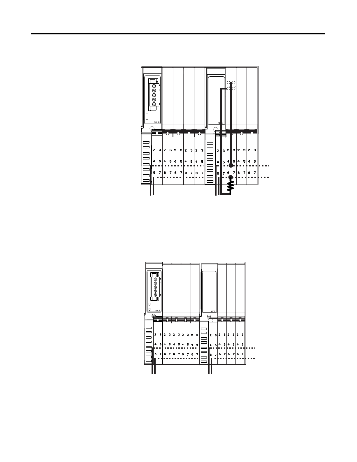
Install POINT I/O Modules 49
PDN IB2 IB4IV2 IV4 FPD OW2OW2OW2
C
V
L2/N
L1
AC Power Bus
Digital
Power Bus
01 01 0101 01
001
01
1
PDN IB2
IB4
OB2E OB4E
12V
12V DC
42009
FPD
IB2 IB4 IV2
C
24V
Digital I/O
Power Bus
Digital I/O
Power Bus
OB4E
This configuration changes the power bus voltage for AC modules.
Wiring Using a 1734-FPD Module to Create a New DC Power Bus
This configuration changes power bus voltage for 12/24V DC systems.
Rockwell Automation Publication 1734-UM001E-EN-P - July 2013
Page 66

50 Install POINT I/O Modules
42009
01 01 01 01 01
001
01
1
24V DC
Analog I/O
Power Bus
24V
24V
C
Digital I/O
Power Bus
PDN OB2E OB4E FPD IE2C OE2C OE2C
IB4
IB2
41970
C
V
NC
C
V
NC
NC = No Connection
CHAS GND = Chassis Ground
C = Common
V = Supply
CHAS GND
CHAS GND
System
Power
Field
Power
1734-EP24DC
Wiring Using a 1734-FPD Module to Create a New Analog Power Bus
This configuration isolates noisy digital I/O power from sensitive analog I/O
power.
Rockwell Automation Publication 1734-UM001E-EN-P - July 2013
1734-EP24DC Expansion Power Supply
Page 67

12/24V DC Wiring Diagram
NC NC
C
VV
C
V DC
V = 12/24V DC, C = Common
CHAS GND = Chassis ground
This DC supply is
connected to the
internal power bus.
3
5
7
01
2
4
6
Do not connect 120/240V AC
power to this supply.
CHAS
GND
CHAS
GND
0101 01 01 0101 0101
Adapter
Status
DeviceNet
Status
PointBus
Status
1734-ADN
DeviceNet
Power
System
Power
1734-EP24DC
DeviceNet
Power
System
Power
EP24DC
ADN
Example of continued power.
12/24V DC only
1734adn4
O
B
2
E
O
B
4
E
I
B
4
I
B
2
I
E
2
C
I
E
2
V
O
E
2
C
ATT ENTI ON: Use the 1734-EP24DC expansion power supply only with
adapter class products. This 1734-EP24DC power supply cannot be used
with a 1734-PDN module or 1734D POINTBlock modules. Do not connect
120/240V AC power to this supply.
Install POINT I/O Modules 51
Connect Terminal Terminals (for continuing power)
+V DC 6 7
-V DC 4 5
Chas Gnd 2 3
12/24V DC becomes the internal power bus for modules to the right.
Example of Continuing Power
Rockwell Automation Publication 1734-UM001E-EN-P - July 2013
Page 68
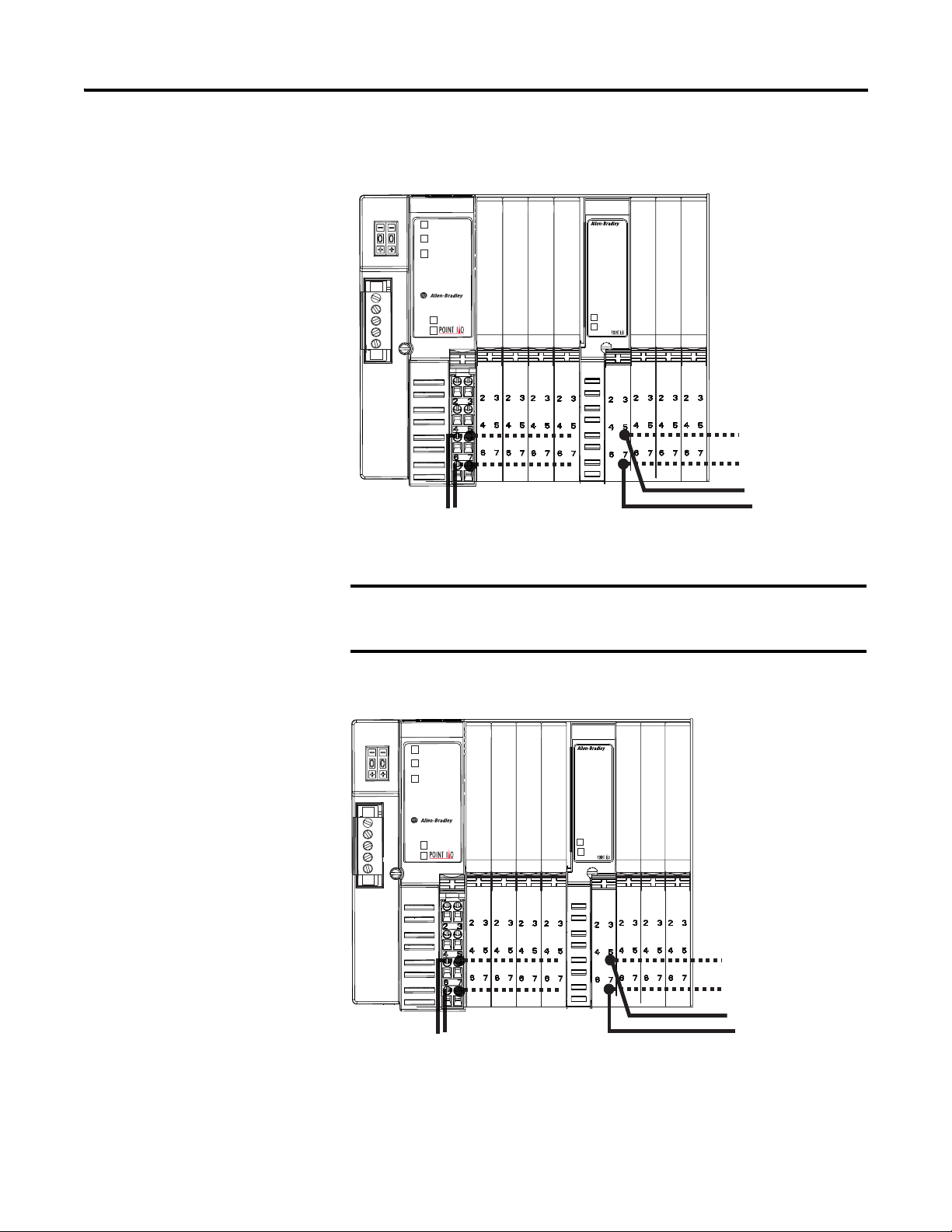
52 Install POINT I/O Modules
IMPORTANT
0101 01 01 0101 0101
Adapter
Status
DeviceNet
Status
PointBus
Status
1734-ADN
DeviceNet
Power
System
Power
1734-EP24DC
DeviceNet
Power
System
Power
EP24DC
ADN
12/24V DC
Digital Supply
1734adn4A
I
B
2
I
B
4
O
B
2
E
O
B
4
E
I
E
2
C
I
E
2
C
O
E
2
C
12/24V DC
Analog Supply
0101 01 01 0101 0101
Adapter
Status
DeviceNet
Status
PointBus
Status
1734-ADN
DeviceNet
Power
System
Power
1734-EP24DC
DeviceNet
Power
System
Power
EP24DC
ADN
24V DC Supply
1734adn4A
I
B
2
O
B
2
E
O
B
4
E
I
E
2
C
O
E
2
C
12V DC Supply
I
B
2
O
B
2
E
Example of Functional Partitioning
The 1734-EP24DC expansion power supply can be used with POINT I/O
adapters only. This 1734-EP24DC power supply cannot be used with a
1734-PDN module or 1734D POINTBlock modules.
Example of Logical Partitioning
Rockwell Automation Publication 1734-UM001E-EN-P - July 2013
Page 69

1734-EPAC AC Expansion Power Supply
L2/N
L1
NC
L2/N
L1
NC
NC = No Connection
PE = Protective Earth Ground
L2/N = Neutral
L1 = 120/240V AC
PE
PE
NC
PE
L2/N
L1 L1
L2/N
V AC
L1 = 120/240V AC
L2/N = 120/240V AC
PE = Protective Earth Ground
Connect ground wire to
PE terminal.
PE
This AC supply will be
connected to the internal
power bus.
NC
0
2
3
1
4
5
6
7
Install POINT I/O Modules 53
120/240V AC Wiring Diagram
Connect Terminal Terminals (for continuing power)
L1 (120/240V AC) 6 7
L2/N( Neutral) 4 5
PE (Protective Earth ground) 2 3
120/240V AC becomes the internal power bus for modules to the right.
Rockwell Automation Publication 1734-UM001E-EN-P - July 2013
ATT ENTI ON: If you connect or disconnect wiring while field side power
is on, an electrical arc can occur. This could cause an explosion in
hazardous location installations.
Be sure that power is removed or the area is nonhazardous before
proceeding.
Page 70

54 Install POINT I/O Modules
IMPORTANT
0101 01 01 0101 01 01
Adapter
Status
DeviceNet
Status
PointBus
Status
1734-ADN
DeviceNet
Power
System
Power
1734-EPAC
Field
Power
System
Power
0101 0101
1734-EPAC
Field
Power
System
Power
I
B
2
I
B
4
O
B
2
E
O
B
4
E
I
A
2
I
A
2
O
A
2
I
M
2
I
M
2
O
A
2
1734-EPAC
1734-EPAC
1734-ADN
12/24V DC
Digital Supply
120V AC Supply
46131
240V AC Supply
ATTENTION: Use the 1734-EPAC AC expansion power supply only with
adapter class products.
The 1734-EPAC AC expansion power supply can be used only with
POINT I/O adapters.
Example of Functional Partitioning
Rockwell Automation Publication 1734-UM001E-EN-P - July 2013
Page 71

Example of Logical Partitioning
0101 01 01 0101 0101
Adapter
Status
DeviceNet
Status
PointBus
Status
1734-ADN
DeviceNet
Power
System
Power
1734-EPAC
Field
Power
System
Power
I
E
2
C
I
E
2
V
O
E
2
C
O
E
2
V
I
A
2
O
A
2
O
W
2
1734-ADN
1734-EPAC
24V DC Supply
120V AC Supply
46130
The 1734-ARM
module requires no
external wiring.
46129
NC
NC = No connection
NC
NC
NC
NC
NC
NC
NC
Install POINT I/O Modules 55
1734-ARM Address Reserve Module
Rockwell Automation Publication 1734-UM001E-EN-P - July 2013
Page 72

56 Install POINT I/O Modules
1734
VTM
0
1
1734
CTM
0
1
1734-VTM
1734-CTM
Voltage Out
Voltage Out
Voltage Out
Voltage Out
Common
Common
Common
Common
46128
Voltage Out = 0 to 7
Common = 0 to 7
Common
Common
Common
Common
Voltage Out
Voltage Out
Voltage Out
Voltage Out
46127
V = Voltage Out
C = Common
In 0
In 1
In 2
In 3
In 4
In 5
In 6 In 7
0
2
3
4
5
6
7
0
1
2
3
4
5
6
7
0
1
2
3
4
5
6
7
V
V
V
V
V
VV
V
C
C
C
C
C
C
CC
1734-IB8
1734-VTM
1734-CTM
Prox
Prox
1
1734-IB8
3-wire
2-wire
1734-CTM and 1734-VTM Modules
Sink Input Wiring Diagram
Rockwell Automation Publication 1734-UM001E-EN-P - July 2013
Page 73

Source Input Wiring Diagram
V = Voltage Out
C = Common
In 0
In 1
In 2
In 3
In 4
In 5
In 6 In 7
0
2
3
4
5
6
7
0
1
2
3
4
5
6
7
0
1
2
3
4
5
6
7
C
C
C
C
C
CC
C
V
V
V
V
V
V
VV
1734-IB8
1734-CTM
1734-VTM
Prox
Prox
1
1734-IB8
3-wire
2-wire
1734-CTM
1734-OV8
Load
Load
Load
Load
Out 7
Out 0
Out 1
Out 2
Out 3
Out 4
Out 5
Out 6
V = Voltage Out
C
CC
C
C
C
C
C
5
1
3
7
0
4
5
6
2
1
3
7
0
4
6
2
1734-VTM
1734-OV8
Load
Load
Load
Load
Out 7
Out 0
Out 1
Out 2
Out 3
Out 4
Out 5
Out 6
V = Voltage Out
V
VV
V
V
V
V
V
5
1
3
7
0
4
5
6
2
1
3
7
0
4
6
2
Install POINT I/O Modules 57
Source Output Wiring Diagram
Sink Output Wiring Diagram
Rockwell Automation Publication 1734-UM001E-EN-P - July 2013
Page 74

58 Install POINT I/O Modules
C = Common
1734
CTM
1734
VTM
V = Voltage Out
Adapter
Power
Supply
Other
Devices
General Purpose Wiring Diagram
Rockwell Automation Publication 1734-UM001E-EN-P - July 2013
Page 75

Install POINTBlock I/O Modules
0
1
2
3
4
5
6
7
0
1
2
3
4
5
6
7
0-9
10-60
Inputs
Outputs
42004
10’s Node Address Rotary Switch
1’s Node Address Rotary Switch
Module Status
Network Status
I/O status
Chapter
3
About This Chapter
Wiring POINTBlock Modules
Read this chapter for information about how to wire POINTBlock I/O modules
to include the following:
• 1734D-IB8XOB8 POINTBlock 8 DC In/8 DC Out Modules
• 1734D-IB8XOW8 POINTBlock 8 DC In/8 Relay Out Modules
• 1734D-IA8XOA8 POINTBlock 8 AC In/8 AC Out Modules
• 1734D-IA8XOW8 POINTBlock 8 AC In/8 Relay Out Modules
• 1734D-IA16 POINTBlock 16 AC Input Modules
• 1734D-IB16 POINTBlock 16 DC Input Modules
1734D-IB8XOB8 POINTBlock 8 DC In/8 DC Out Modules
Rockwell Automation Publication 1734-UM001E-EN-P - July 2013
Page 76

78 Install POINTBlock I/O Modules
V dc
NC
NC
Cin
Vin
12/24V dc
Power
NC = No Connection Chas Gnd = Chassis Ground
C = Common V = Supply
NC
NC
Cin
Vin
0
2
C
V
1
3
C
V
4
6
C
V
5
7
C
V
0
2
C
C
1
3
C
C
4
6
C
C
5
7
C
C
Field
Power
Inputs Outputs
This supply will be connected to the internal power bus.
01
23
45
67
01
23
45
67
01
23
45
67
01
23
45
67
01
23
45
67
RTB 0 RTB 1 RTB 2 RTB 3 RTB 4
Prox
In 0 In 1
In 2
C
VV
C
In 3
Prox ProxProx
V = 12/24V dc
C = Common
3
5
7
01
2
4
6
3-wire2-wire
8 Input/8 Output Module Wiring Diagram
Rockwell Automation Publication 1734-UM001E-EN-P - July 2013
Sink Input Wiring
Diagram
Channel Input Terminal Common Voltage
Remote Termination Block 1
00 4 6
11 5 7
22 4 6
33 5 7
Remote Termination Block 2
40 4 6
51 5 7
62 4 6
73 5 7
Connect common on 3-wire proximity switches.
12/24V DC is supplied through the internal power bus.
Page 77

Install POINTBlock I/O Modules 79
Out 0
Out 1
Out 3Out 2
CC
CC
Load Load
Load
Load
V = 12/24V dc, C = Common
Field power is supplied from internal power bus
0
2
6
3
1
7
45
ATTENTION: When connecting more than one wire in a
termination point, make sure that both wires are the same gauge
and type.
Output Wiring Diagram
Channel Output Terminal Common Terminal Power
Remote Termination Block 3
Channel 0 0 6
Channel 1 1 7
Channel 2 2 4
Channel 3 3 5
Remote Termination Block 4
Channel 4 0 6
Channel 5 1 7
Channel 6 2 4
Channel 7 3 5
Module power is supplied from the internal power bus.
ATTENTION: When connecting more than one wire in a
termination point, make sure that both wires are the same gauge
and type.
Outputs are electronically protected to 0.75 A. Module outputs are selectable for
latched mode or auto-reset mode. (Latched/auto reset is set by module, not by
individual channel.) Each channel is assigned a bit in the data table to indicate the
faulted condition. Outputs in the latched mode can only be reset with a user
command to the module.
Rockwell Automation Publication 1734-UM001E-EN-P - July 2013
Page 78

80 Install POINTBlock I/O Modules
DeviceNet
Connection
Red
White
Bare
Blue
Black
-V
+V
CAN - High
Shield
CAN - Low
Latch Mode Functionality
State Indication Error Bit
Off Dark 0
On Yellow 0
Faulted/On Red 1
Faulted/Off Flashing Red 1
To reset an output, the reset bit for the output can be set, or the output bit must
be cycled off/on.
Auto Retry Mode Functionality
State Indication Error Bit
Off Dark 0
On Yellow 0
Faulted/On Red 1
Faulted/Off Flashing Red 1
In auto retry, the output recovers once the fault is removed.
DeviceNet Connector Wiring
Rockwell Automation Publication 1734-UM001E-EN-P - July 2013
Page 79

Install POINTBlock I/O Modules 81
0
1
2
3
4
5
6
7
0
1
2
3
4
5
6
7
0-9
10-60
Inputs
Outputs
42004
10’s Node Address Rotary Switch
1’s Node Address Rotary Switch
Module Status
Network Status
I/O status
V dc
NC
NC
Cin
Vin
12/24V dc
Power
NC = No Connection Chas Gnd = Chassis Ground
C = Common V = Supply
NC
NC
Cin
Vin
0
2
C
V
1
3
C
V
4
6
C
V
5
7
C
V
0A
OB
2A
2B
1A
1B
3A
3B
4A
4B
6A
6B
5A
5B
7A
7B
Field Power
Inputs Outputs
This supply will be connected to the internal power bus.
01
23
45
67
01
23
45
67
01
23
45
67
01
23
45
67
01
23
45
67
RTB 0 RTB 1 RTB 2 RTB 3 RTB 4
1734D-IB8XOW8 POINTBlock 8 DC In/8 Relay Out Modules
8 Input/8 Relay Output Module Wiring Diagram
Rockwell Automation Publication 1734-UM001E-EN-P - July 2013
Page 80
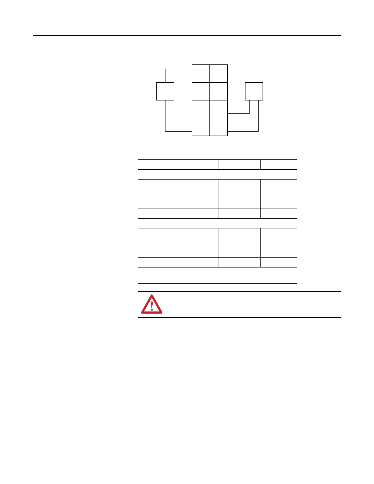
82 Install POINTBlock I/O Modules
Prox
In 0 In 1
NC
C
VV
C
NC
Prox
V = 12/24V dc
C = Common
3-wire2-wire
3
5
7
01
2
4
6
Sink Input Wiring
Channel Input Terminal Common Voltage
Remote Termination Block 1
00 4 6
11 5 7
22 4 6
33 5 7
Remote Termination Block 2
40 4 6
51 5 7
62 4 6
73 5 7
Connect common on 3-wire proximity switches.
12/24V DC is supplied through the internal power bus.
Rockwell Automation Publication 1734-UM001E-EN-P - July 2013
ATTENTION: When connecting more than one wire in a
termination point, make sure that both wires are the same gauge
and type.
Page 81

Install POINTBlock I/O Modules 83
Out
0A
Out
0B
Out
1A
Out
1B
Load
Power
Supply
Out = Output channel relay contacts
Power Supply = can range from +5V DC to 240V ac
C = Common
0
2
4
6
3
5
7
1
Power
Supply
Load
Out
2A
Out
2B
Out
3A
Out
3B
DeviceNet
Connection
Red
White
Bare
Blue
Black
-V
+V
CAN - High
Shield
CAN - Low
Output Wiring Diagram (Load Powered by External Power)
Channel Output Common Supply
Remote Termination Block 3
0A 0 Not used Not used
0B 2
1A 1
1B 3
2A 4
2B 6
3A 5
3B 7
Remote Termination Block 4
4A 0 Not used Not used
4B 2
5A 1
5B 3
6A 4
6B 6
7A 5
7B 7
Supply voltage can range from +5V DC to 240V ac, depending on relay load.
12/24V DC power for the module is provided by the internal power bus.
ATTENTION: When connecting more than one wire in a
termination point, make sure that both wires are the same gauge
and type.
DeviceNet Connector Wiring
Rockwell Automation Publication 1734-UM001E-EN-P - July 2013
Page 82

84 Install POINTBlock I/O Modules
0
1
2
3
4
5
6
7
0
1
2
3
4
5
6
7
0-9
10-60
Inputs
Outputs
42004
10’s Node Address Rotary Switch
1’s Node Address Rotary Switch
Module Status
Network Status
I/O status
V ac
NC
NC
L2in
L1in
120V ac
Power
NC = No Connection Chas Gnd = Chassis Ground
L2/N = AC Return/Neutral L1 = AC Power
NCNC0
2
L2
L1
1
3
L2
L1
4
6
L2
L1
5
7
L2
L1
0
2
L2
L2
1
3
L2
L2
4
6
L2
L2
5
7
L2
L2
Field Power
Inputs Outputs
L1in
L2in
This supply will be connected to the internal power bus.
RTB 0 RTB 1 RTB 2 RTB 3 RTB 4
01
23
45
67
01
23
45
67
01
23
45
67
01
23
45
67
01
23
45
67
1734D-IA8XOA8 POINTBlock 8 AC In/8 AC Out Modules
1734D-IA8XOA8 POINTBlock 8 AC In/8 AC Out Modules Wiring Diagram
Rockwell Automation Publication 1734-UM001E-EN-P - July 2013
Page 83

Install POINTBlock I/O Modules 85
Prox
In 0 In 1
In 2
L2
L1 L1
L2
In 3
Prox
L1 = 120V ac
L2 = Return
3
5
7
01
2
4
6
Input Wiring Diagram
Channel Input Terminal Return Voltage
Remote Termination Block 1
0046
1157
2246
3357
Remote Termination Block 2
4046
5157
6246
7357
120V AC is supplied through the internal power bus.
ATTENTION: When connecting more than one wire in a
termination point, make sure that both wires are the same gauge
and type.
Rockwell Automation Publication 1734-UM001E-EN-P - July 2013
Page 84

86 Install POINTBlock I/O Modules
Load
In 0 In 1
In 2
L2
L2
L2
L2
In 3
Load
L1 = 120V ac
L2 = Return
3
5
7
01
2
4
6
Load
Load
DeviceNet
Connection
Red
White
Bare
Blue
Black
-V
+V
CAN - High
Shield
CAN - Low
Output Wiring Diagram
Channel
Output Terminal Common Terminal Power
Remote Termination Block 3
Channel 0 0 6
Channel 1 1 7
Channel 2 2 4
Channel 3 3 5
Remote Termination Block 4
Channel 4 0 6
Channel 5 1 7
Channel 6 2 4
Channel 7 3 5
Module power is supplied from the internal power bus.
ATTENTION: When connecting more than one wire in a
termination point, make sure that both wires are the same gauge
and type.
DeviceNet Connector Wiring
Rockwell Automation Publication 1734-UM001E-EN-P - July 2013
Page 85

Install POINTBlock I/O Modules 87
0
1
2
3
4
5
6
7
0
1
2
3
4
5
6
7
0-9
10-60
Inputs
Outputs
42004
10’s Node Address Rotary Switch
1’s Node Address Rotary Switch
Module Status
Network Status
I/O status
V ac
NC
NC
L2in
L1in
120V ac
Power
NC = No connection
L2/N = AC Return/Neutral
L1 = AC Power
NCNC0
2
L2
L1
1
3
L2
L1
4
6
L2
L1
5
7
L2
L1
0A
0B
2A
2B
1A
1B
3A
3B
4A
4B
6A
6B
5A
5B
7A
7B
Field Power
Inputs Outputs
L1in
L2in
This supply will be connected to the internal power bus.
RTB 0 RTB 1 RTB 2 RTB 3 RTB 4
01
23
45
67
01
23
45
67
01
23
45
67
01
23
45
67
01
23
45
67
1734D-IA8XOW8 POINTBlock 8 AC In/8 Relay Out Modules
1734D-IA8XOW8 POINTBlock 8 AC In/8 Relay Out Modules Wiring Diagram
Rockwell Automation Publication 1734-UM001E-EN-P - July 2013
Page 86

88 Install POINTBlock I/O Modules
Prox
In 0
In 1
In 2
L2
L1
L1
L2
In 3
Prox
L1 = 120V ac
L2 = Return
3
5
7
0
1
2
4
6
Input Wiring Diagram
Channel Input Terminal Return Voltage
Remote Termination Block 1
00 4 6
11 5 7
22 4 6
33 5 7
Remote Termination Block 2
40 4 6
51 5 7
62 4 6
73 5 7
120V AC is supplied through the internal power bus.
Rockwell Automation Publication 1734-UM001E-EN-P - July 2013
ATTENTION: When connecting more than one wire in a
termination point, make sure that both wires are the same gauge
and type.
Page 87

Install POINTBlock I/O Modules 89
Out 0A
Out 0B
Out 1A
Out 1B
Load
Power
Supply
Out = Output channel relay contacts
L1 = 120V ac
L2 = Return
Load Powered by External Power
0
2
4
6
3
5
7
1
Power
Supply
Load
Out 2A
Out 2B
Out 3A
Out 3B
DeviceNet
Connection
Red
White
Bare
Blue
Black
-V
+V
CAN - High
Shield
CAN - Low
Output Wiring Diagram
Channel Output Common Supply
Remote Termination Block 3
0A 0 Not used Not used
0B 2
1A 1
1B 3
2A 4
2B 6
3A 5
3B 7
Remote Termination Block 4
4A 0 Not used Not used
4B 2
5A 1
5B 3
6A 4
6B 6
7A 5
7B 7
Supply voltage is 120V ac.
120V AC power for the module is provided by the internal power bus.
Rockwell Automation Publication 1734-UM001E-EN-P - July 2013
ATTENTION: When connecting more than one wire in a
termination point, make sure that both wires are the same gauge
and type.
DeviceNet Connector Wiring
Page 88
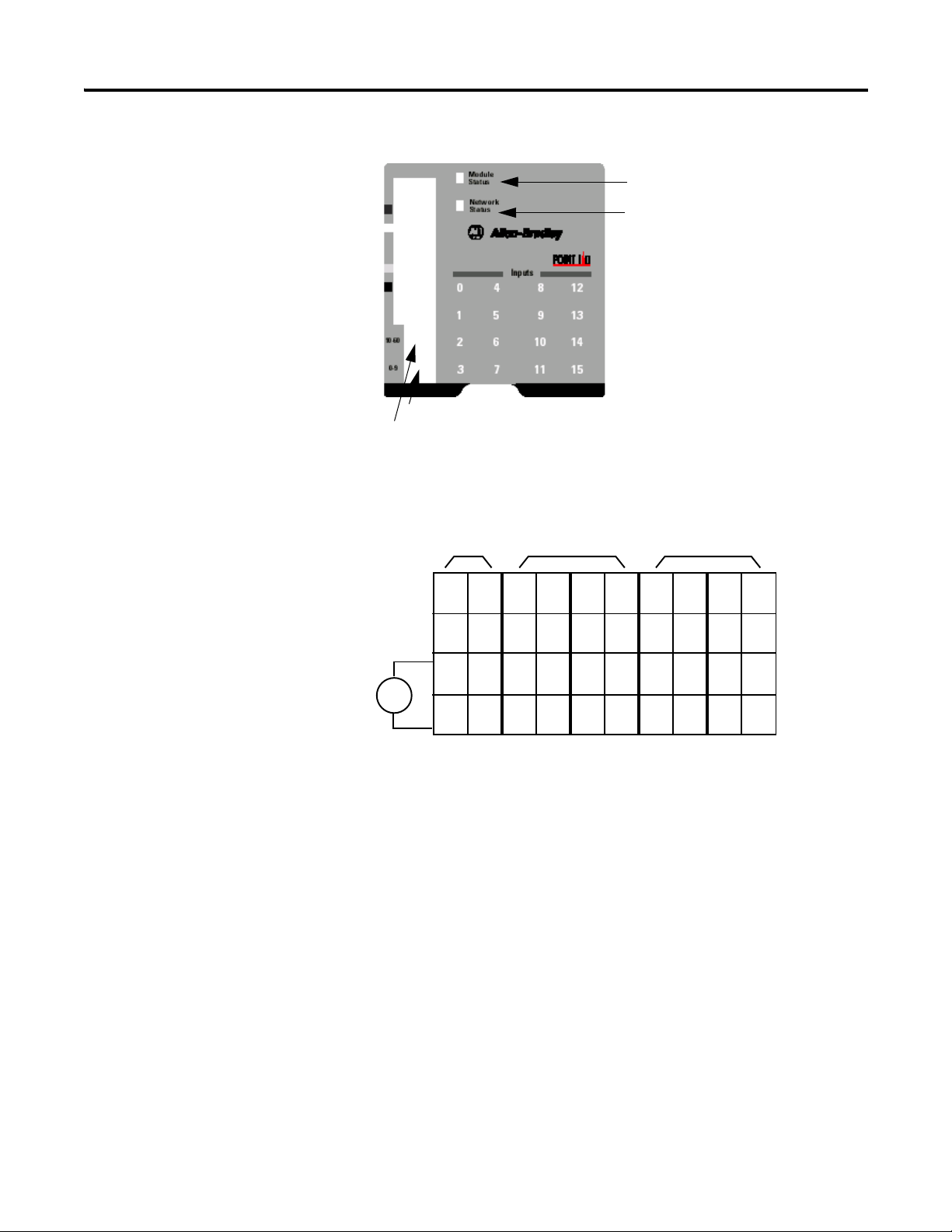
90 Install POINTBlock I/O Modules
42004
10’s Node Address Rotary Switch
1’s Node Address Rotary Switch
Module Status
Network Status
I/O Status
V ac
NC
NC
L2in
L1in
120V ac
Power
NC = No Connection Chas Gnd = Chassis Ground
L2/N = AC Return/Neutral L1 = AC Power
NCNC0
2
L2
L1
1
3
L2
L1
4
6
L2
L1
5
7
L2
L1
8
10
L2
L1
9
11
L2
L1
12
14
L2
L1
13
15
L2
L1
Field Power
Inputs
L1in
L2in
This supply will be connected to the internal power bus.
RTB 0 RTB 1 RTB 2 RTB 3 RTB 4
01
23
45
67
01
23
45
67
01
23
45
67
01
23
45
67
01
23
45
67
1734D-IA16 POINTBlock 16 AC Input Modules
Wire the 16 AC Input Module Wiring Diagram
Rockwell Automation Publication 1734-UM001E-EN-P - July 2013
Page 89

Input Wiring Diagram
Prox
In 0 In 1
In 2
L2
L1 L1
L2
In 3
Prox
L1 = 120V ac
L2 = Return
3
5
7
01
2
4
6
Repeat for RTB 2, 3 and 4
RTB 1
ATTENTION: When connecting more than one wire in a
termination point, make sure that both wires are the same gauge
and type.
Install POINTBlock I/O Modules 91
Channel Input Terminal Return Voltage
Remote Termination Block 0
Field Power
Block
Vin (L1) 6 and/or 7
Return (L2/N) 4 and/or 5
Remote Termination Block 1
00 6
11 7
22 6
33 7
Remote Termination Block 2
40 6
51 7
62 6
73 7
Remote Termination Block 3
80
91
10 2
11 3
6
7
6
7
Remote Termination Block 4
12 0
13 1
6
7
Rockwell Automation Publication 1734-UM001E-EN-P - July 2013
Page 90

92 Install POINTBlock I/O Modules
DeviceNet
Connection
Red
White
Bare
Blue
Black
-V
+V
CAN - High
Shield
CAN - Low
42004
10’s Node Address Rotary Switch
1’s Node Address Rotary Switch
Module Status
Network Status
I/O status
Channel Input Terminal Return Voltage
14 2
15 3
120V AC is supplied through the internal power bus.
6
7
DeviceNet Connector Wiring
1734D-IB16 POINTBlock 16 DC Input Modules
Rockwell Automation Publication 1734-UM001E-EN-P - July 2013
Page 91

16 DC Input Module Wiring Diagram
V dc
NC
NC
Cin
Vin
12/24V dc
NC
NC
Cin
Vin
0
2
C
V
1
3
C
V
4
6
C
V
5
7
C
V
8
10
C
V
9
11
C
V
12
14
C
V
13
15
C
V
Field
Power
Inputs
This supply will be connected to the internal power bus.
01
23
45
67
01
23
45
67
01
23
45
67
01
23
45
67
01
23
45
67
RTB 0 RTB 1 RTB 2 RTB 3 RTB 4
NC =
No Connection
C = Common
Chas Gnd =
Chassis Ground
V = Supply
Prox
In 0 In 1
In 2
C
VV
C
In 3
Prox ProxProx
V = 12/24V dc
C = Common
3
5
7
01
2
4
6
3-wire2-wire
RTB 1
Repeat for RTB 2, RTB 3 and RTB 4.
Install POINTBlock I/O Modules 93
Sink Input Wiring Diagram
Channel Input Terminal Common Voltage
Remote Termination Block 0
Field Power
Block
Vin (supply) 6 and 7
Common) 4 and 5
Rockwell Automation Publication 1734-UM001E-EN-P - July 2013
Remote Termination Block 1
0046
1157
2246
3357
Remote Termination Block 2
4046
5157
Page 92

94 Install POINTBlock I/O Modules
DeviceNet
Connection
Red
White
Bare
Blue
Black
-V
+V
CAN - High
Shield
CAN - Low
Channel Input Terminal Common Voltage
Remote Termination Block 0
Field Power
Block
Vin (supply) 6 and 7
Common) 4 and 5
62 4 6
73 5 7
Remote Termination Block 3
80 4 6
91 5 7
10 2 4 6
11 3 5 7
Remote Termination Block 4
12 0 4 6
13 1 5 7
14 2 4 6
15 3 5 7
Connect common on 3-wire proximity switches.
12/24V DC is supplied through the internal power bus.
ATTENTION: When connecting more than one wire in a
termination point, make sure that both wires are the same gauge
and type.
DeviceNet Connector Wiring
Rockwell Automation Publication 1734-UM001E-EN-P - July 2013
Page 93

POINT I/O Module Data
Chapter
4
About This Chapter
Digital Input Modules
Read this chapter for information about module status, input, output, and
configuration data, and default data maps forPOINT I/O modules to include
the following:
• Digital Input Modules
• Digital Output Modules
• Relay Output Modules
• Analog Input Modules
• Analog Output Modules
• POINTBlock I/O Modules
Read this section for information about digital input modules.
Digital DC Input Modules
The 1734 digital DC input modules feature the following:
• 24V DC nominal DC inputs
• Input range of 10...28.8V dc
• 2, 4, or 8 sinking or sourcing style inputs
• Autobaud (will match baud of existing devices on the network)
• Selectable input filter times (0…65 ms with 1 ms default)
• Sequential auto addressing
I/O messages are sent to (consumed) and received from (produced) these
POINT I/O modules. These messages are mapped into the processor memory.
These POINT I/O modules produce one byte of input data (scanner Rx). They
do not consume I/O data (scanner Tx).
(1) These are mapped through scan lists in DeviceNet networks and Direct, Listen Only, or Rack Optimized
connections in ControlNet and EtherNet/IP networks.
Rockwell Automation Publication 1734-UM001E-EN-P - July 2013
(1)
Page 94

96 POINT I/O Module Data
Default Data Map for the 1734-IB2 and 1734-IV2 Input Modules
Message Size: 1 Byte
76543210
Produces (scanner Rx) Not used Ch1 Ch0
Consumes (scanner Tx) No consumed data
Where: Ch0 = input channel 0, Ch1 = input channel 1, 0 = off, 1 = on
Default Data Map for the 1734-IB4 and 1734-IV4 Input Modules
Message Size: 1 Byte
76543210
Produces (scanner Rx) Not used Ch3 Ch2 Ch1 Ch0
Consumes (scanner Tx) No consumed data
Where: Ch0 = input channel 0, Ch1 = input channel 1, Ch2 = input channel 2, Ch3 = input channel 3, 0 = off, 1 = on
Default Data Map for the 1734-IB8 and 1734-IV8 Input Modules
Message Size: 1 Byte
76543210
Produces (scanner Rx) Ch7 Ch6 Ch5 Ch4 Ch3 Ch2 Ch1 Ch0
Consumes (scanner Tx) No consumed data
Where: Ch0 = input channel 0, Ch1 = input channel 1, Ch2 = input channel 2, Ch3 = channel 3, Ch4 = input channel 4, Ch5 = input channel
5, Ch6 = input channel 6, Ch7 = input channel 7, 0 = off, 1 = on
Default Data Map for 1734-IB4D Module - Produced Assembly Instance 101
Message Size: 2 Bytes
76 5 43 2 1 0
Produce 0 (Rx) Fault 3 Fault 2 Fault 1 Fault 0 Input 3 Input 2 Input 1 Input 0
Produce 1 (Rx) SC 3 SC 2 SC 1 SC 0 OW 3 OW 2 OW 1 OW 0
Consume (Tx) No consumed data
Where: OW = open wire, SC = short circuit, fault = open wire or short circuit.
Default Data Map for 1734-IB4D Module - Produced Assembly Instance 23
Message Size: 1 Byte
76 54 32 1 0
Produce 0 (Rx) Fault 3 Fault 2 Fault 1 Fault 0 Input 3 Input 2 Input 1 Input 0
Consume (Tx) No consumed data
Where: Fault = open wire or short circuit.
Rockwell Automation Publication 1734-UM001E-EN-P - July 2013
Page 95

POINT I/O Module Data 97
Default Data Map for 1734-IB4D Module - - Configuration Assembly Instance 103
Message Size: 18 Bytes
7 6543 2 1 0
Consume 0 Input 0 Off to On Filter Byte 0
Consume 1 Input 0 Off to On Filter Byte 1
Consume 2 Input 0 On to Off Filter Byte 0
Consume 3 Input 0 On to Off Filter Byte 1
Consume 4 Input 1 Off to On Filter Byte 0
Consume 5 Input 1 Off to On Filter Byte 1
Consume 6 Input 1 On to Off Filter Byte 0
Consume 7 Input 1 On to Off Filter Byte 1
Consume 8 Input 2 Off to On Filter Byte 0
Consume 9 Input 2 Off to On Filter Byte 1
Consume 10 Input 2 On to Off Filter Byte 0
Consume 11 Input 2 On to Off Filter Byte 1
Consume 12 Input 3 Off to On Filter Byte 0
Consume 13 Input 3 Off to On Filter Byte 1
Consume 14 Input 3 On to Off Filter Byte 0
Consume 15 Input 3 On to Off Filter Byte 1
Consume 16 Autobaud Disable Enable OW3 Enable OW2 Enable OW1 Enable OW0
Consume 17 Produced Assembly Instance
Produce (Tx) No produced data
Where: OW = open wire.
Digital AC Input Modules
The 1734 digital AC input modules feature the following:
• 120 or 220V AC nominal are AC inputs
• Input range of 65…132 for 120V AC inputs; 159…264 for 220V AC
inputs
• Two sinking style inputs
• Autobaud (will match baud of existing devices on the network)
• Selectable input filter times (0…65 ms with 1 ms default)
• Sequential auto addressing
I/O messages are sent to (consumed) and received from (produced) these
POINT I/O modules. These messages are mapped into the processor memory.
(1) These are mapped through scan lists in DeviceNet networks and Direct, Listen Only, or Rack-optimized
connections in ControlNet and EtherNet/IP networks.
Rockwell Automation Publication 1734-UM001E-EN-P - July 2013
(1)
Page 96

98 POINT I/O Module Data
These POINT I/O modules produce one byte of input data (scanner Rx). They
do not consume I/O data (scanner Tx).
Default Data Map for the 1734-IA2 and 1734-IM2 Input Modules
Message Size: 1 Byte
76543210
Produces (scanner Rx) Ch1 Ch0
Consumes (scanner Tx) No consumed data
Where: Ch0 = channel 0, Ch1 = channel 1; 0 = off, 1 = on
Default Data Map for the 1734-IA4 and 1734-IM4 Input Modules
Message Size: 1 Byte
76543210
Produces (scanner Rx) Ch3 Ch2 Ch1 Ch0
Consumes (scanner Tx) No consumed data
Where: Ch0 = channel 0, Ch1 = channel 1; Ch2 = channel 2, Ch3 = channel 3,
0 = off, 1 = on
Digital Output Modules
Read this section for information about digital output modules.
Digital DC Output Modules
The features of DC output modules include the following:
• 24V DC outputs with a range of 10…28.8V dc
• Output diagnostic features are incorporated to assist in troubleshooting
• Current limited outputs of up to 2 A with respect to their DC return
• Autobaud (will match baud of existing devices on the network)
• Sequential auto addressing
I/O messages are sent to (consumed) and received from (produced) these
POINT I/O modules. These messages are mapped into the processor memory.
These POINT I/O modules produce one byte of input data (scanner Rx). They
consume one byte of output data (Scanner Tx).
(1)
Rockwell Automation Publication 1734-UM001E-EN-P - July 2013
Page 97

POINT I/O Module Data 99
Default Data Map for 1734-OB2, 1734-OB2E, and 1734-OV2E Output Module
Message Size: 1 Byte
76543 2 1 0
Produces
(scanner Rx)
Not used Ch1Ch0Channel status
(1734-OB2E module only)
(1)
Where: 0 = no error, 1 = error
Message Size: 1 Byte
76543 2 1 0
Consumes
Not used Ch1Ch0Channel state
(scanner Tx)
Where: 0 = off, 1 = on
(1) The 1734-OB2, 1734-OB4, and 1734-OB8 Digital DC Output modules do produce one byte of data (Scanner
RX), but it is always zero.
Default Data Map for 1734-OB4, 1734-OB4E, and 1734-OV4E Output Module
Message Size: 1 Byte
76543 2 1 0
Produces
(scanner Rx)
Not used Ch3 Ch2 Ch1 Ch0 Channel status
(1734-OB4E module
(1)
only)
Where: 0 = no error, 1 = error
Message Size: 1 Byte
76543 2 1 0
Consumes
Not used Ch3 Ch2 Ch1 Ch0 Channel state
(scanner Tx)
Where: 0 = off, 1 = on
(1) The 1734-OB2, 1734-OB4, and 1734-OB8 Digital DC Output modules do produce one byte of data (Scanner
RX), but it is always zero.
Default Data Map for 1734-OB8, 1734-OB8E, and 1734-OV8E Output Module
Message Size: 1 Byte
76543210
Produces
(scanner Rx)Ch7Ch6Ch5Ch4Ch3Ch2Ch1Ch0
Channel status
(1734-OB8E module
(1)
only)
Where: 0 = no error, 1 = error
Message Size: 1 Byte
Rockwell Automation Publication 1734-UM001E-EN-P - July 2013
Page 98

100 POINT I/O Module Data
Default Data Map for 1734-OB8, 1734-OB8E, and 1734-OV8E Output Module
76543210
Consumes
Channel state
(scanner Tx)Ch7Ch6Ch5Ch4Ch3Ch2Ch1Ch0
Where: 0 = off, 1 = on
(1) The 1734-OB2, 1734-OB4, and 1734-OB8 Digital DC Output modules do produce one byte of data (Scanner RX),
but it is always zero.
Default Data Map for the 1734-OB2EP Output Module
Message Size: 1 Byte
76543210
Produces
Not used Ch1 Ch0 Channel status
(scanner Rx)
Where: 0 = no error, 1 = error
Message Size: 1 Byte
76543210
Consumes
Not used Ch1 Ch0 Channel state
(scanner Tx)
Where: 0 = Off, 1 = On
Digital AC Output Modules
The 1734-OA2 AC output module features include the following:
• 120V AC outputs with a range of 74…264V AC (120/220V AC nominal)
• Each output is rated at 0.10 A minimum to 0.75 A maximum
• Autobaud (will match baud of existing devices on the network)
• Sequential auto addressing
D
efault Data Map for the 1734-OA2 Output Module
76543 2 1 0
Produces (scanner Rx) No produced data
Consumes (scanner
Tx)
Where: 0 = Off, 1 = On
Not used Ch1 Ch0 Channel state
Rockwell Automation Publication 1734-UM001E-EN-P - July 2013
Page 99
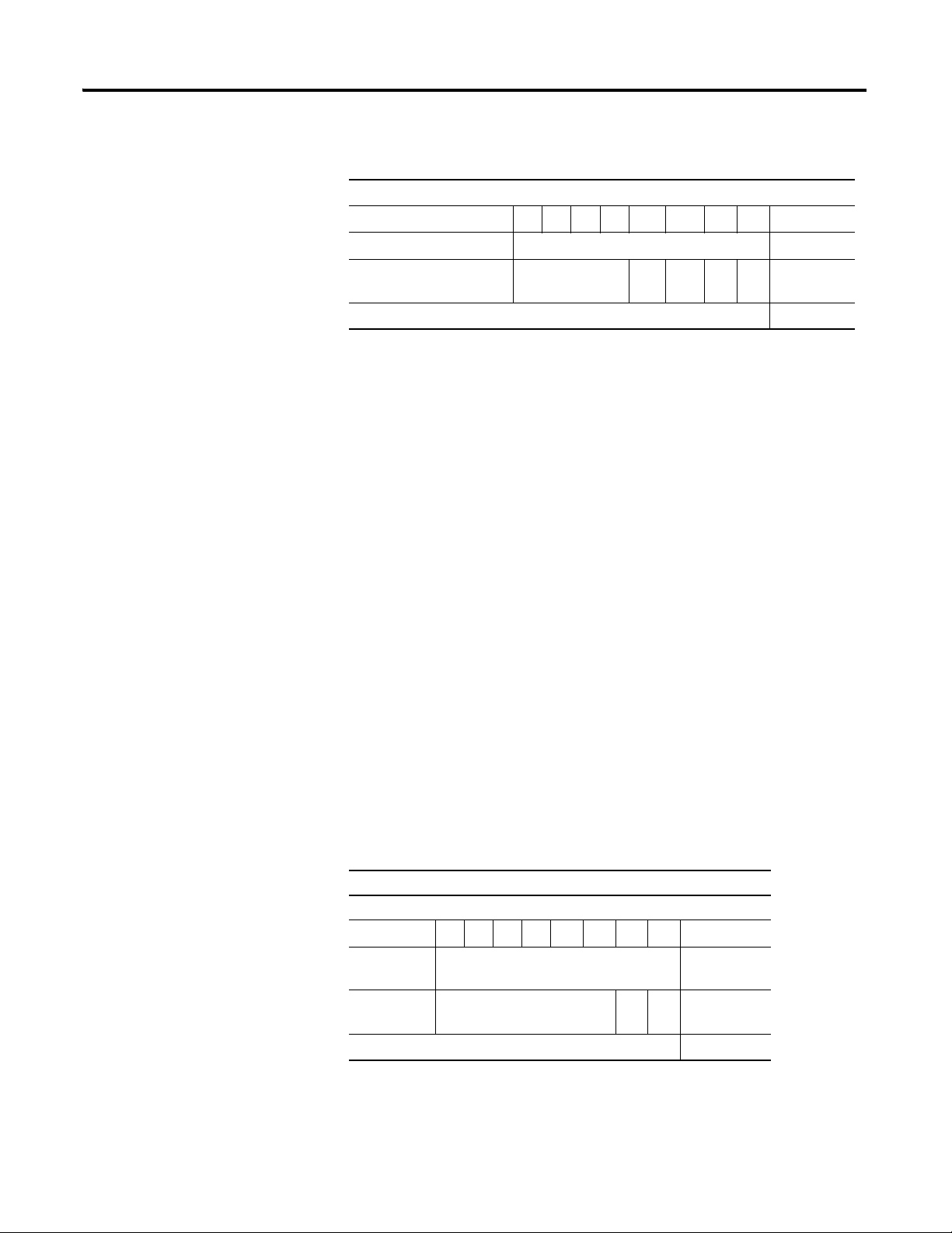
POINT I/O Module Data 101
Default Data Map for 1734-OA4 Modules
76543 2 1 0
Produces (scanner Rx) No produced data
Consumes (scanner Tx) Not used Ch 3Ch 2 Ch1Ch0Channel
state
Where: 0 = Off, 1 = On
Relay Output Modules
The relay output modules consist of 1734-OW2 and 1734-OW4 2-relay output
modules and 1734-OX2 4-relay output modules. Features of the 1734-OW2 and
1734-OW4 relay modules include the following:
• Typ e A Norm al ly Op en r el ays
• Sink or source a current with respect to power or return
• Contact outputs isolated from each other
• Each output rated 5…240V dc/V rms at 2 A (current is load dependant)
• Autobaud (will match baud of existing devices on the network)
• Sequential auto addressing
Features of the 1734-OX2 relay modules include the following:
• Two Form C isolated (normally open; normally closed)
electromechanical relays
• Sink or source a current with respect to power or return
• Contact outputs isolated from each other
• Each output rated 5…240V dc/V rms at 2 A (current is load dependant)
• Autobaud (will match baud of existing devices on the network)
• Sequential auto addressing
I/O messages are sent to (consumed) and received from (produced) these
POINT I/O modules. These messages are mapped into the processor memory.
Default Data Map for the 1734-OW2 Output Module
Message Size: 1 Byte
76543210
Produces
(scanner Rx)
Consumes
(scanner Tx)
Where: 0 = off, 1 = on
Rockwell Automation Publication 1734-UM001E-EN-P - July 2013
No produced data
Not used Ch1Ch0Channel state
Page 100

102 POINT I/O Module Data
Default Data Map for the 1734-OW4 Output Module
Message Size: 1 Byte
76543210
Analog Input Modules
Produces
(scanner Rx)
Consumes
(scanner Tx)
Where: 0 = off, 1 = on
Default Data Map for the 1734-OX2 Relay Output Module
Message Size: 1 Byte
Produces
(scanner Rx)
Consumes
(scanner Tx)
Where: 0 = NO contact off, NC contact on
1 = NO contact on, NC contact off
No produced data
Not used Ch3Ch2Ch1Ch0Channel state
76543 2 1 0
No produced data
Not used Ch1Ch0Channel state
The 1734-IE2C Analog Input Module is a two-channel module that converts an
analog input current to a digital value. The module resolution is 16 bits across 0
to 21 mA. The module has two modes.
• 0…20 mA
• 4…20 mA (default mode)
• Scaling to any 16-bit signed integer (–32,768…+32,767) -
Default for 1734-IE2C scalers are +3277 @ 4 mA for low
and +16,383 @ 20 mA for high
• Operates in Unipolar mode
The 1734-IE2V Analog Input Module is a two-channel module that converts an
analog input voltage to a digital value. The module resolution is 16 bits across 10…+10V. The module has two modes.
• 0…10V DC (default mode)
• +/- 10V dc
• Scaling to any 16-bit signed integer (–32,768…+32,767) -
Default for 1734-IE2V scalers are 0 @ 0V for low
and +10,000 @ 100V for high
• Operates in Unipolar or Bipolar modes
Rockwell Automation Publication 1734-UM001E-EN-P - July 2013
 Loading...