

Allen-Bradley 1732D-IB8M8, 1732D-OB8EM8, 1732D-IB8M12, 1732D-OB8EM12, 1732D-8CFGM12 Installation Instructions Manual
...Page 1
Installation Instructions
DeviceNet 1732 ArmorBlock I/O, Series A
(Cat. Nos. 1732D-IB8M12, -IB8M8, -OB8EM12, -OB8EM8,
-8CFGM12, -8CFGM8)
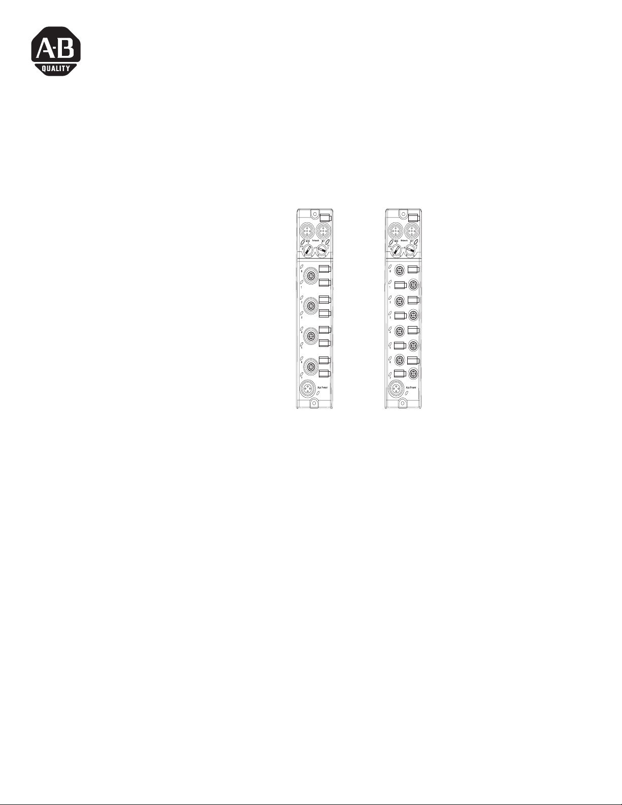
M12 Style
Connectors
M8 Style
Connectors
31433-M
The DeviceNet 1732D ArmorBlock™ I/O family consists of
stand-alone 24V dc I/O modules that communicate via the
DeviceNet network. The sealed IP67 housing of these modules
requires no enclosure (Note that environmental requirements other
than IP67 may require an additional appropriate enclosure.) I/O
connectors are sealed M8 (pico) or M12 (micro) styles while the
network and auxiliary power connectors are sealed M12 style.
Important User Information
Solid state equipment has operational characteristics differing from those of
electromechanical equipment. Safety Guidelines for the Application, Installation and
Maintenance of Solid State Controls (Publication SGI-1.1 available from your local
Rockwell Automation sales office or online at http://www.ab.com/manuals/gi)
describes some important differences between solid state equipment and hard-wired
electromechanical devices. Because of this difference, and also because of the wide
variety of uses for solid state equipment, all persons responsible for applying this
equipment must satisfy themselves that each intended application of this equipment
is acceptable.
In no event will Rockwell Automation, Inc. be responsible or liable for indirect or
consequential damages resulting from the use or application of this equipment.
The examples and diagrams in this manual are included solely for illustrative
purposes. Because of the many variables and requirements associated with any
particular installation, Rockwell Automation, Inc. cannot assume responsibility or
liability for actual use based on the examples and diagrams.
No patent liability is assumed by Rockwell Automation, Inc. with respect to use of
information, circuits, equipment, or software described in this manual.
1 Publication 1732D-IN001B-EN-E - May 2004
Page 2
2 DeviceNet 1732 ArmorBlock I/O, Series A
SHOCK HAZARD
Important User Information
Reproduction of the contents of this manual, in whole or in part, without written
permission of Rockwell Automation, Inc. is prohibited.
Throughout this manual we use notes to make you aware of safety considerations.
WARNING
Identifies information about practices or circumstances that
can cause an explosion in a hazardous environment, which
may lead to personal injury or death, property damage, or
economic loss.
ATTENTION
IMPORTANT
ATTENTION
Identifies information about practices or circumstances that
can lead to personal injury or death, property damage, or
economic loss. Attentions help you:
• identify a hazard
• avoid a hazard
• recognize the consequence
Identifies information that is critical for successful application
and understanding of the product.
Labels may be located on or inside the module to alert people
that dangerous voltage may be present.
Environment and Enclosure
This equipment is intended for use in overvoltage Category II
applications (as defined in IEC publication 60664-1), at altitudes
up to 2000 meters without derating.
This equipment is considered Group 1, Class A industrial
equipment according to IEC/CISPR Publication 11. Without
appropriate precautions, there may be potential difficulties
ensuring electromagnetic compatibility in other environments
due to conducted as well as radiated disturbance.
This equipment is supplied as "enclosed" equipment. It should
not require additional system enclosure when used in locations
consistent with the enclosure type ratings stated in the
Specifications section of this publication. Subsequent sections of
this publication may contain additional information regarding
specific enclosure type ratings, beyond what this product
provides, that are required to comply with certain product safety
certifications.
NOTE: See NEMA Standards publication 250 and IEC publication
60529, as applicable, for explanations of the degrees of
protection provided by different types of enclosure. Also, see the
appropriate sections in this publication, as well as the
Allen-Bradley publication 1770-4.1 ("Industrial Automation
Wiring and Grounding Guidelines"), for additional installation
requirements pertaining to this equipment.
Publication 1732D-IN001B-EN-E - May 2004
Page 3

DeviceNet 1732 ArmorBlock I/O, Series A 3
Install Your ArmorBlock I/O Module
ATTENTION
To install the module:
• Set the node address
• Mount the module
• Connect the cord sets
• Attach the network cables
• Communicate with the module
Preventing Electrostatic Discharge
This equipment is sensitive to electrostatic discharge,
which can cause internal damage and affect normal
operation. Follow these guidelines when you handle
this equipment:
• Touch a grounded object to discharge potential
static.
• Wear an approved grounding wriststrap.
• Do not touch connectors or pins on component
boards.
• Do not touch circuit components inside the
equipment.
• If available, use a static-safe workstation.
• When not in use, store the equipment in
appropriate static-safe packaging.
Set the Node Address
Valid node addresses are 00 through 63.
Set the node address using either the rotary switches, RSNetWorx for
DeviceNet, DeviceNetManager, or another software configuration
tool. Setting the switches at any number from 64 to 99 lets the
software have address control.
Each module is shipped set for node address 63. Remove the caps on
the front of the module to access the switches. The two switches are:
• X10 (most significant digit) - left side of module
• X1 (least significant digit) - right side of module
To reset th e nod e addre ss, use a small bla de scre wdri ver to ro tate th e
switches. Line up the small black dot on the switch with the number
setting you wish to use and then cycle power.
Publication 1732D-IN001B-EN-E - May 2004
Page 4

4 DeviceNet 1732 ArmorBlock I/O, Series A
The rotary switches are read periodically. If the switches have been
changed since the last time they were read and they no longer match
the on line address, a minor fault will occur, which is indicated by a
flashing red MOD LED. Settings between 64 and 99 cause the mod ule
to use the
last valid node address stored internally. Example: The last
setting internally was 40. If a change is made to 68, and th en you
power up, the address will default to 40.
Set Node Address
This example shows the default
node address set at 63.
31433-M
The module is equipped with AutoBaud detect. AutoBaud lets the
module read the settings already in use on your DeviceNet network
and automatically adjusts to follow those settings.
Publication 1732D-IN001B-EN-E - May 2004
Page 5
DeviceNet 1732 ArmorBlock I/O, Series A 5
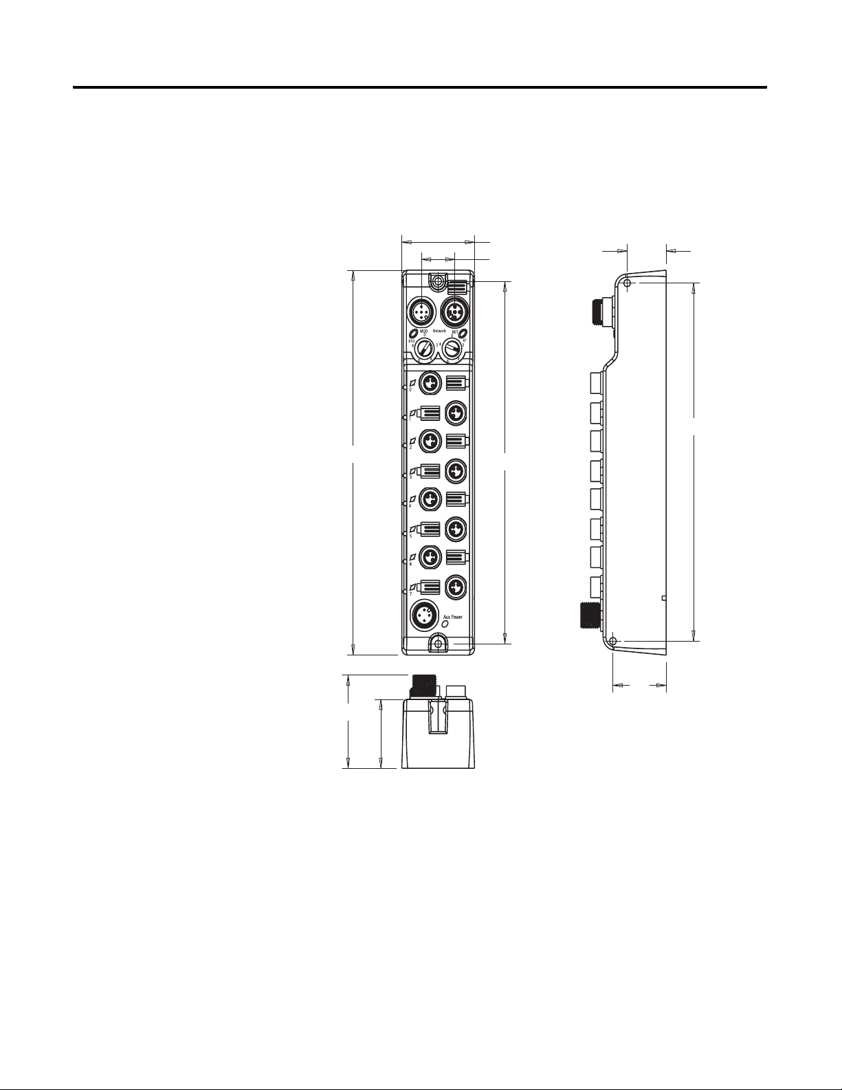
Mount the Module
Each module has two sets of mounting holes that are used to mount
the module directly to a panel or machine. The module can be fron t
or side mounted. Mounting holes accommodate #6 (M3) pan head
screws. The torque specification is 6 in-lbs.
.78in.
(19.8 mm)
6.56in. (166.5mm)
7.05in. (179mm)
1.46in. (37mm)
.67in. (17mm)
6.64in. (168.6mm)
1.70in.
(43.3mm)
1.06in.
(27mm)
Side Mounting
9577597-101
1.26 in.
(32mm)
Front Mounting
Publication 1732D-IN001B-EN-E - May 2004
Page 6

6 DeviceNet 1732 ArmorBlock I/O, Series A
Mount the Module in High Vibration Areas
If you will mount the module in an area that is subject to shock or
vibration, we recommend that you use a flat and lock washer to
mount the module. Mount the flat and lock washer as shown in the
following illustration. Torque the mounting screws to 6 in-lbs.
Lock Washer
Connect the Input/Output Cord Sets to the ArmorBlock Module
Flat Washer
43619
The ArmorBlock family offers 5-pin micro-style PCB mounting
connectors or 3-pin pico-style PCB mounting connectors.
We provide caps to cover the unused connectors on your module.
Connect the quick-disconnect cord sets you selected for your module
to the appropriate ports.
Publication 1732D-IN001B-EN-E - May 2004
Page 7
DeviceNet 1732 ArmorBlock I/O, Series A 7
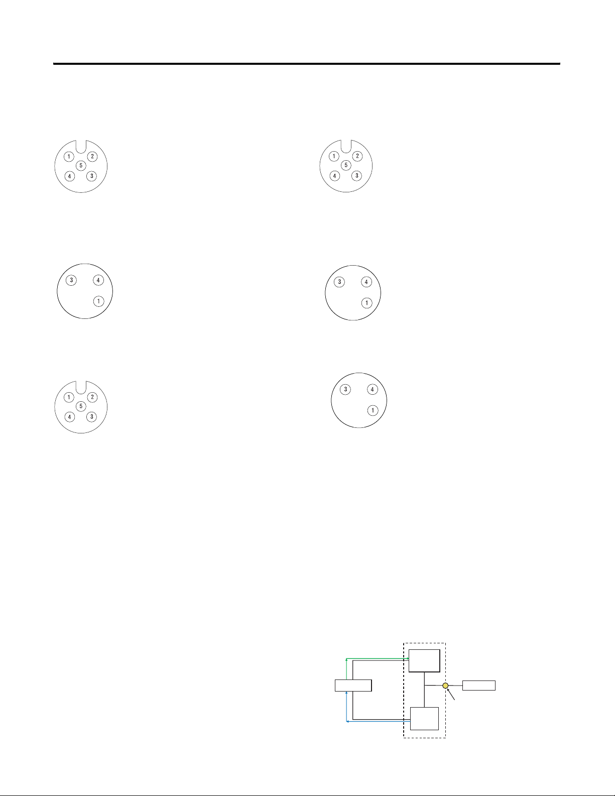
5-Pin Micro-Style (12mm) Female Connectors
Pinout diagrams for the I/O connectors are shown below.
Input Connector
Cat. Nos. 1732D-IB8M12
(view into connector)
Pin 1 Sensor Source Voltage
Pin 2 Input B
Pin 3 Return
Pin 4 Input A
Pin 5 Not used
Cat. Nos. 1732D-IB8M8
Pin 1 Sensor Source voltage
Pin 3 Return
Pin 4 Input
Self-configuring Connector
Cat. Nos. 1732D-8CFGM12
Pin 1 Sensor Source Voltage
41452
Pin 2 Input or Output B
Pin 3 Return
Pin 4 Input or Output A
Pin 5 Not Used
3-Pin Pico-Style (8mm) Female Connectors
Input Connector
(view into connector)
Self-configuring Female Connectors
(view into connector)
41452
43583
43583
Output Connector
Cat. Nos. 1732D-OB8EM12
(view into connector)
Pin 1 Not Used
Pin 2 Output B
Pin 3 Return
Pin 4 Output A
Pin 5 Not Used
Output Connector
Cat. Nos. 1732D-OB8EM8
(view into connector)
Pin 1 Not Used
Pin 3 Return
Pin 4 Output
Self-configuring Connector
Cat. Nos. 1732D-8CFGM8
(view into connector)
Pin 1 Sensor Source Voltage
Pin 3 Return
Pin 4 Input or Output
The self-configuring modules (1732D-8CFGM8 and 1732D-8CFGM12)
contain both input and output functionality.
If an I/O point is to be an output, dedicate that point as an output
with a wired load and energize it through a control program.
Energized outputs will show an associ ated acti ve in put, wh ich ca n b e
used as a feedback mechanism to ensure that the output is turned on.
If an I/O point is to be an input, wire the input device as normal and
leave the associated output un-energized at all times.
I/O Self-configuring Circuitry
Turn Output On
Scan List
Input is on
(or output is on)
Output
Circuit
Device
Input
Circuit
Connection Pin
43601
Publication 1732D-IN001B-EN-E - May 2004
Page 8
8 DeviceNet 1732 ArmorBlock I/O, Series A
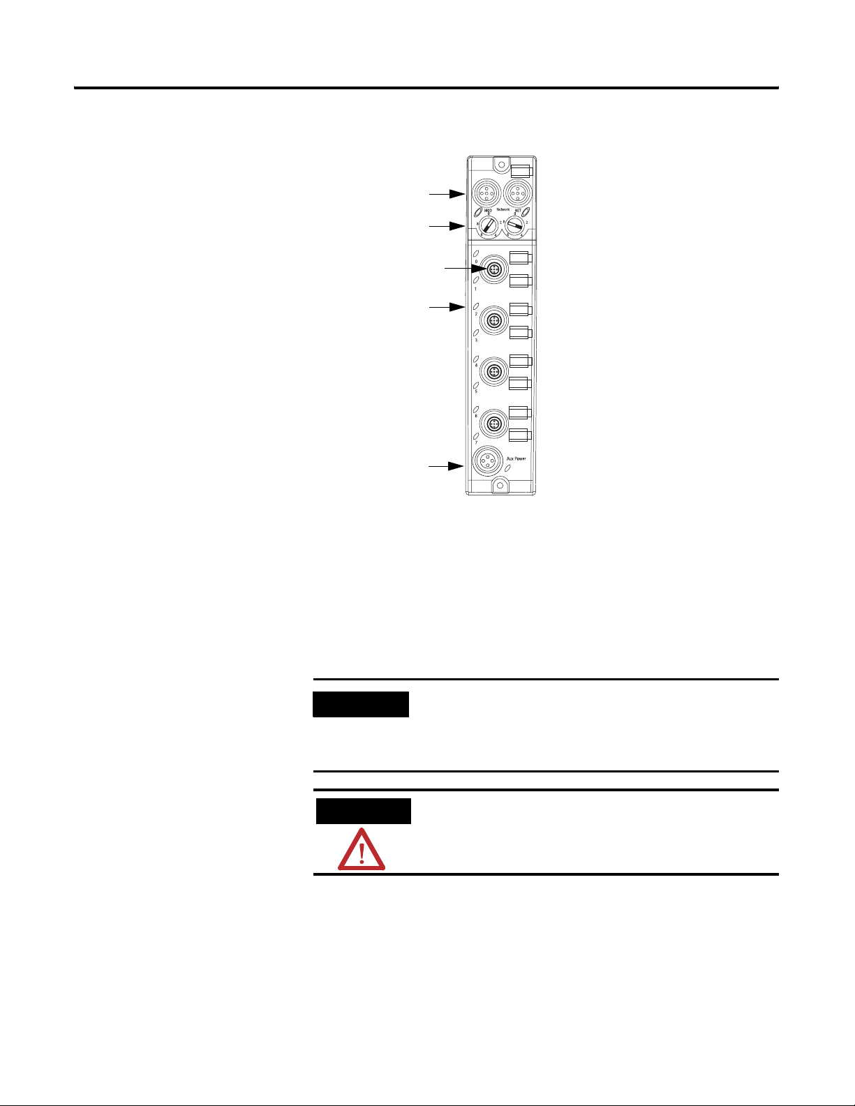
Refer to the illustration below for configuration operations.
DeviceNet
Node Address
4-12mm or 8-8mm I/O
Connectors
Status LED
Sensor and
Actuator Power
MSD
All I/O are 24V dc sink in/source out
- 8 input
LSD
- 8 output
- 8 input or output points
- any mix of 8 (e.g., 7 + 1; 3 + 5)
Output short circuit protected
Output monitoring in “self-configuring” style
43602
Please refer to publication 889-CG001 for Rockwell Au tomation cables
and cord sets offerings or access the Connection Systems website at:
http://www.ab.com/sensors/products/connection_systems/index.html
For M12 (micro) style connections, please reference th e 889D
products. For M8 (pico) style connections, please reference the 889P
products
IMPORTANT
.
ATTENTION
If the devices (sensors) connected to the input
connections require Class 2 powe r to operate, the
auxiliary power connections of this equipment must
be powered by a Class 2 source.
Make sure all connectors and caps are securely
tightened to properly seal the connections against
leaks and maintain IP67 requirements.
Publication 1732D-IN001B-EN-E - May 2004
Page 9

DeviceNet 1732 ArmorBlock I/O, Series A 9
Attach DeviceNet Cables
Attach Auxiliary Power Cable
Attach the 5-pin (12mm) DeviceNet style connectors as shown below.
DeviceNet Input Male Connector
(view into connector)
Pin 1 Drain
Pin 2 V+
Pin 3 VPin 4 CAN_H
43584
Pin 5 CAN_L
DeviceNet Output Female Connector
(view into connector)
Pin 1 Drain
Pin 2 V+
Pin 3 VPin 4 CAN_H
41452
Pin 5 CAN_L
To terminate the module, use the second DeviceNet connector and a
Rockwell Automation terminator resistor (Cat. No. 1485A-T1D5).
Attach the 4-pin (12mm) style connector as shown below.
(view into connector)
Pin 1 24V dc
Pin 2 24V dc
Pin 3 Return
Pin 4 Return
Communicate With Your ArmorBlock I/O Module
43587
Input and output devices are powered through the module’s I/O
connectors. Removing auxiliary power will deactivate all sensors and
actuators unless they are powered from a separate source. If a
separate source is used, devices may still be active, even if auxiliary
power is removed. To ensure that auxiliary power controls the
activation/deactivation of sensors and actuators, always wire input
sensors and output actuators directly to the I/O connectors.
This ArmorBlock module’s I/O is exchanged with the master through
a poll, change-of-state, or cyclic connection.
Cyclic - allows configuration of the block as an I/O client. The block
will produce and consume its I/O cyclically at the rate configured.
Polled - a master initiates communication by sending its polle d I/O
message to the module. The module consumes the message, updates
outputs, and produces a response. The response has input data.
Publication 1732D-IN001B-EN-E - May 2004
Page 10

10 DeviceNet 1732 ArmorBlock I/O, Series A
Change-of-State - productions occur when an input changes or a
fault condition occurs. If no input or fault condition change occurs
within the expected packet rate, a heartbeat production occurs. This
heartbeat production tells the scanner module that the I/O module is
alive and ready to communicate. Consumption occurs when data
changes and the master produces new output data to the I/O block.
1732D-8CFGM8 and 1732D-8CFGM12
Byte Bit 7 Bit 6 Bit 5 Bit 4 Bit 3 Bit 2 Bit 1 Bit 0
Produced 0 I7 I6 I5 I4 I3 I2 I1 I0
Consumes 0 O7 O6 O5 O4 O3 O2 O1 O0
Where: I=Input O=Output
Note that the 1732D-8CFGM8 and 1732D-8CFGM12 self-assigning
modules contain both input and output functionality. These modu le s
do not need to be configured.
If an I/O point is to be an output, dedicate that point as an output
with a wired load and energize it through a control program.
If an I/O point is to be an input, wire the input device as normal and
leave the associated output un-energized at all times.
1732D-IB8M12 and 1732D-IB8M8
Byte Bit 7 Bit 6 Bit 5 Bit 4 Bit 3 Bit 2 Bit 1 Bit 0
Produced 0 I7 I6 I5 I4 I3 I2 I1 I0
Where: I=Input
1732D-OB8EM8 and 1732D-OB8EM12
Byte Bit 7 Bit 6 Bit 5 Bit 4 Bit 3 Bit 2 Bit 1 Bit 0
Consumes 0 O7 O6 O5 O4 O3 O2 O1 O0
Where: O=Output
Publication 1732D-IN001B-EN-E - May 2004
The DeviceNet Network uses advanced network technology,
producer/consumer communication, to increase network functionali ty
and throughput. Visit our web site at
for producer/consumer technology infor mation and updates.
http://www.ab.com/networks
Page 11
DeviceNet 1732 ArmorBlock I/O, Series A 11
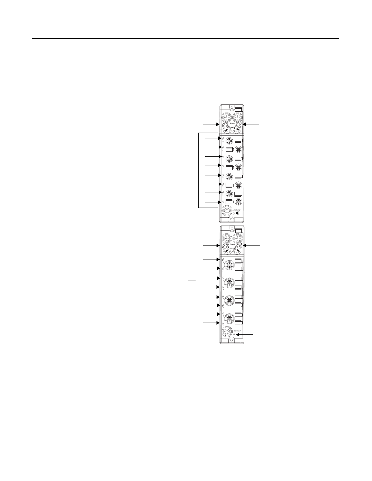
Troubleshoot With the Indicators
This module has the following indicators:
• Network and Module status indicator for DeviceNet
• Auxiliary Power indicator
• Individual I/O status indicators for inputs and outputs
M8 Style Connectors
Module Indicator Network Indicator
I/O Status Indicators
Auxiliary Power Indicator
43820
M12 Style Connectors
Module Indicator Network Indicator
I/O Status Indicators
Auxiliary Power Indicator
43821
Publication 1732D-IN001B-EN-E - May 2004
Page 12

12 DeviceNet 1732 ArmorBlock I/O, Series A
The following table describes network status indicators.
Network Status Indicator - NS
Module’s State Indicator Status
Not Powered/
Not on line
On line, connected Solid
On line, not connected Flashing
Critical link failure Solid
Connection time out Flashing
Off Device is not on-line:
Green
Green
Red
Red
• The device has not completed the
dup_MAC_id test yet.
• The device may not be powered yet.
The device is operating in a normal condition and
the device is on line with connections in the
established state.
• As a Group 2 device, it means that the device
is allocated to a master.
The device is on line with no connections in the
established state.
• The device has passed the dup_MAC_id
test, is on line, but has no established
connections to other nodes.
• As a Group 2 device, it means that the device
is not allocated to a master.
Failed communication device - The device has
detected an error that has rendered it incapable of
communication on the network (dup_MAC_id
failure or bus-off).
An I/O connection has timed out.
The following table describes module status indicators.
Publication 1732D-IN001B-EN-E - May 2004
Module Status Indicator - MS
Module’s State Indicator Status
No Power Off There is no power applied to the module.
Device Operational Green The module is operating normally.
Module needs
commissioning
Minor Fault Flashing Red Recoverable fault.
Critical Fault Red Watchdog timeout or the module has an
Flashing Green The module needs commissioning due to
missing, incomplete or incorrect configuration.
unrecoverable fault and may need replacing.
Page 13

DeviceNet 1732 ArmorBlock I/O, Series A 13
The following table describes the auxiliary power indicator.
Auxiliary Power
Indication Status
None No Auxiliary Power
Solid Green Auxiliary Power Present
The following table describes individual I/O status indicators.
I/O Status Indicators
Function Point Indicator Condition
Outputs None
Yellow
Inputs None
Yellow
Output not energized
Output energized
No valid input
Valid input
This product has been tested at an Open DeviceNet Vendor
Association, Inc. (ODVA) authorized independent test laboratory and
found to comply with ODVA Con formance Test. Please contact the
ODVA website (http://www.odva.org) for listing of products tested by
ODVA independent test labs for further details.
Specifications
DeviceNet 1732 ArmorBlock I/O Series A
Input Specifications
Inputs 61131-2 Type 3 Compatible
Sensor Source Current, Maximum (per input) 50mA
Sensor Source Current, Maximum (per module) 400mA
Sensor Source Voltage
(auxiliary power=12-30V dc)
Maximum
Minimum
On-state Voltage
Maximum
Minimum
On-state Current, Maximum 5mA
Off-state Voltage, Maximum 5V dc
Off-state Current, Maximum 1.5mA
Input Delay Time - ON to OFF and OFF to ON, Maximum 0-16000 µs
Output Specifications
Outputs 61131-2 Compatible
Off-state Peak Blocking Voltage, Minimum 30V
On-state Voltage Drop, Maximum 0.5V
On-state Current, Maximum 0.5A
Off-state Leakage, Maximum 50µA
Module Current, Maximum (all outputs) 4.0A
Surge Current for 10ms, repeatable every 2s, Maximum 1.2A
Following are specifications for the 1732 ArmorBlock I/O modules.
30V
11V
30V dc
11V dc
Publication 1732D-IN001B-EN-E - May 2004
Page 14

14 DeviceNet 1732 ArmorBlock I/O, Series A
DeviceNet 1732 ArmorBlock I/O Series A
General Specifications
Isolation Type tested to 500V ac for 60 seconds between auxiliary power and network (I/O to logic)
Dimensions Inches (Millimeters) 1.9H x 2.7W x 6.9D (48H x 69W x 174D)
Indicators Module Status - red/green
Network Status - red/green
Auxiliary Power - green
Point LED - yellow
Communication Rate • 125Kbps @ 500 meters(1640 feet) for thick cable, fl at media length 375 meters (1378 feet)
• 250Kbps @ 200 meters(600 feet) for thick cable, flat media length 150 meters (492 feet)
• 500Kbps @ 100 meters (330 feet) for thick cable, flat media length 75 meters (246 feet)
DeviceNet Power Voltage
Maximum
Minimum
Current
Maximum
Minimum
Auxiliary Power - Voltage for I/O Channel Power
Maximum
Minimum
25V dc
11V dc
100mA
100mA
30V dc max
11V dc
Current for I/O Channel
-IB8, Maximum
-OB8E, Maximum
-8CFG, Maximum
450mA
4A
4A
Operating Temperature IEC 60068-2-1 (Test Ad, Operating Cold),
IEC 60068-2-2 (Test Bd, Operating Dry Heat),
IEC 60068-2-14 (Test Nb, Operating Thermal Shock):
-20 to 60°C (-4 to 140°F)
Storage Temperature IEC 60068-2-1 (Test Ab, Un-packaged Non-operating Cold),
IEC 60068-2-2 (Test Bb, Un-packaged Non-operating Dry Heat),
IEC 60068-2-14 (Test Na, Un-packaged Non-operating Thermal Shock):
-45 to 85°C (-49 to 185°F)
Relative Humidity IEC 60068-2-30 (Test Db, Un-packaged Non-operating Damp Heat):
5-95% non-condensing
Shock IEC60068-2-27 (Test Ea, Unpackaged Shock):
Operating 30g
Non-operating 50g
Vibration IEC60068-2-6 (Test Fc, Operating):
5g @ 10-500Hz
Conductor Category
1, 2
2
See publication no. 889-CG001
ESD Immunity IEC 61000-4-2:
6kV contact discharges
8kV air discharges
Radiated RF Immunity IEC 61000-4-3:
10V/m with 1kHz sine-wave 80%AM from 30MHz to 2000M Hz
10V/m with 200Hz 50% Pulse 100%AM at 900Mhz
10V/m with 200Hz 50% Pulse 100%AM at 1890Mhz
EFT/B Immunity IEC 61000-4-4:
±2kV at 5kHz on signal ports
±2kV at 5kHz on communications ports
±4kV at 5.0kHz on power ports
Surge Transient Immunity IEC 61000-4-5:
±1kV line-line(DM) and ±2kV line-earth(CM) on signal ports
±1kV line-line(DM) and ±2kV line-earth(CM) on power ports
±2kV line-earth(CM) on shielded ports
Conducted RF Immunity IEC 61000-4-6:
10Vrms with 1kHz sine-wave 80%AM from 150kHz to 80MHz
Emissions CSPR 11:
Group 1, Class A
Enclosure Meets IP65/66/67 (when marked)
Publication 1732D-IN001B-EN-E - May 2004
Page 15

DeviceNet 1732 ArmorBlock I/O, Series A 15
General Specifications (continued)
Weight 0.448 lbs. (0.203 kg)
Certifications:
(when product is marked)
c-UL-us UL Listed Industrial Control Equipment, certif ied for US and Canada
3
CE
European Union 89/336/EEC EMC Directive, compliant with:
EN 61000-6-4; Industrial Emissions
EN 50082-2; Industrial Immunity
EN 61326; Meas./Control/Lab., Industrial Requirements
EN 61000-6-2; Industrial Immunity
C-Tick3Australian Radiocommunications Act, compliant with: AS/NZS CISPR 11;
Industrial Emissions
ODVA ODVA conformance tested to DeviceNet specifications
1. You use this conductor category information for planning conductor routing as described in the system level installation manual.
2. See pub. 1770-4.1, Programmable Controller Wiring and Grounding Guidelines.
3. See the Product Certification link at www.ab.com for Declarations of Conformity, Certificates, and other certification details.
Publication 1732D-IN001B-EN-E - May 2004
Page 16
Rockwell Automation Support
Rockwell Automation provides technical information on the web to assist you in using our products. At
http://support.rockwellautomation.com, you can find technical manuals, a knowledge base of FAQs, technical and
application notes, sample code and links to software service packs, and a MySupport feature that you can customize
to make the best use of these tools.
For an additional level of technical phone support for installation, configuration and troubleshooting, we offer
TechConnect Support programs. For more information, contact your local distributor or Rockwell Automation
representative, or visit http://support.rockwellautomation.com.
Installation Assistance
If you experience a problem with a hardware module within the first 24 hours of installation, please review the
information that's contained in this manual. You can also contact a special Customer Support number for initial help
in getting your module up and running:
United States 1.440.646.3223
Monday – Friday, 8am – 5pm EST
Outside United States Please contact your local Rockwell Automation representative for any technical support
issues.
New Product Satisfaction Return
Rockwell tests all of our products to ensure that they are fully operational when shipped from the manufacturing
facility. However, if your product is not functioning and needs to be returned:
United States Contact your distributor. You must provide a Customer Support case number (see phone
number above to obtain one) to your distributor in order to complete the return process.
Outside United States Please contact your local Rockwell Automation representative for return procedure.
ArmorBlock, RSNetWorx for DeviceNet, and DeviceNetManager are trademarks of Rockwell Automation.
DeviceNet is a trademark of Open DeviceNet Vendor Association.
Publication 1732D-IN001B-EN-E - May 2004 16 PN 957899-53
Supersedes Publication 1732D-IN001A-EN-E - April 2004 Copyright © 2004 Rockwell Automation, Inc. All rights reserved. Printed in the U.S.A.
 Loading...