

Allen-Bradley 1711-P05SISID050S, 1711-P05SISID100S, 1711-P05SISID050T, 1711-P05SISID100T, 1711-P05SISOD050S User Manual
...Page 1

User Manual
Original Instructions
OptiSIS® Safety Instrumented System
Catalog Numbers 1711-P05SISID050S, 1711-P05SISID050T, 1711-P05SISOD050S, 1711-P05SISOD050T, 1711-P05SISID100S,
1711-P05SISID100T, 1711-P05SISOD100S, 1711-P05SISOD100T
AB PLCs
Page 2
Important User Information
Read this document and the documents listed in the additional resources section about installation, configuration, and
operation of this equipment before you install, configure, operate, or maintain this product. Users are required to
familiarize themselves with installation and wiring instructions in addition to requirements of all applicable codes, laws,
and standards.
Activities including installation, adjustments, putting into service, use, assembly, disassembly, and maintenance are
required to be carried out by suitably trained personnel in accordance with applicable code of practice.
If this equipment is used in a manner not specified by the manufacturer, the protection provided by the equipment may
be impaired.
In no event will Rockwell Automation, Inc. be responsible or liable for indirect or consequential damages resulting from
the use or application of this equipment.
The examples and diagrams in this manual are included solely for illustrative purposes. Because of the many variables and
requirements associated with any particular installation, Rockwell Automation, Inc. cannot assume responsibility or
liability for actual use based on the examples and diagrams.
No patent liability is assumed by Rockwell Automation, Inc. with respect to use of information, circuits, equipment, or
software described in this manual.
Reproduction of the contents of this manual, in whole or in part, without written permission of Rockwell Automation,
Inc., is prohibited
Throughout this manual, when necessary, we use notes to make you aware of safety considerations.
WARNING: Identifies information about practices or circumstances that can cause an explosion in a hazardous
environment, which may lead to personal injury or death, property damage, or economic loss.
ATTENTION: Identifies information about practices or circumstances that can lead to personal injury or death, property
damage, or economic loss. Attentions help you identify a hazard, avoid a hazard, and recognize the consequence.
IMPORTANT Identifies information that is critical for successful application and understanding of the product.
Labels may also be on or inside the equipment to provide specific precautions.
SHOCK HAZARD: Labels may be on or inside the equipment, for example, a drive or motor, to alert people that dangerous
voltage may be present.
BURN HAZARD: Labels may be on or inside the equipment, for example, a drive or motor, to alert people that surfaces may
reach dangerous temperatures.
ARC FLASH HAZARD: Labels may be on or inside the equipment, for example, a motor control center, to alert people to
potential Arc Flash. Arc Flash will cause severe injury or death. Wear proper Personal Protective Equipment (PPE). Follow ALL
Regulatory requirements for safe work practices and for Personal Protective Equipment (PPE).
Page 3

Table of Contents
Summary of Changes . . . . . . . . . . . . . . . . . . . . . . . . . . . . . . . . . . . . . . . . . . . .7
Preface . . . . . . . . . . . . . . . . . . . . . . . . . . . . . . . . . . . . . . . . . . . . . . . . . . . . . . . .9
About This Publication. . . . . . . . . . . . . . . . . . . . . . . . . . . . . . . . . . . . . . . . . 9
Terminology. . . . . . . . . . . . . . . . . . . . . . . . . . . . . . . . . . . . . . . . . . . . . . . . . . . 9
About the OptiSIS Solution. . . . . . . . . . . . . . . . . . . . . . . . . . . . . . . . . . . . 10
Catalog Numbers. . . . . . . . . . . . . . . . . . . . . . . . . . . . . . . . . . . . . . . . . . 10
I/O Configurations. . . . . . . . . . . . . . . . . . . . . . . . . . . . . . . . . . . . . . . . 10
Enclosure Options. . . . . . . . . . . . . . . . . . . . . . . . . . . . . . . . . . . . . . . . . 10
Additional Resources . . . . . . . . . . . . . . . . . . . . . . . . . . . . . . . . . . . . . . . . . . 11
Chapter 1
Safety Requirements Introduction. . . . . . . . . . . . . . . . . . . . . . . . . . . . . . . . . . . . . . . . . . . . . . . . . . 13
Safety Architecture . . . . . . . . . . . . . . . . . . . . . . . . . . . . . . . . . . . . . . . . . . . . 13
Fail-safe System . . . . . . . . . . . . . . . . . . . . . . . . . . . . . . . . . . . . . . . . . . . 13
Fault Tolerant System . . . . . . . . . . . . . . . . . . . . . . . . . . . . . . . . . . . . . 14
Safe State . . . . . . . . . . . . . . . . . . . . . . . . . . . . . . . . . . . . . . . . . . . . . . . . . 14
Process Safety Lifecycle, Functional Testing, and Validation . . . . . . 15
Safety Data . . . . . . . . . . . . . . . . . . . . . . . . . . . . . . . . . . . . . . . . . . . . . . . . . . . 15
PFD/PFH Data . . . . . . . . . . . . . . . . . . . . . . . . . . . . . . . . . . . . . . . . . . . 16
Password Protection. . . . . . . . . . . . . . . . . . . . . . . . . . . . . . . . . . . . . . . . . . . 16
Program Enable Key. . . . . . . . . . . . . . . . . . . . . . . . . . . . . . . . . . . . . . . . . . . 17
Diagnostics . . . . . . . . . . . . . . . . . . . . . . . . . . . . . . . . . . . . . . . . . . . . . . . . . . . 18
Certification . . . . . . . . . . . . . . . . . . . . . . . . . . . . . . . . . . . . . . . . . . . . . . . . . . 18
Chapter 2
Installation Introduction. . . . . . . . . . . . . . . . . . . . . . . . . . . . . . . . . . . . . . . . . . . . . . . . . . 19
Installation . . . . . . . . . . . . . . . . . . . . . . . . . . . . . . . . . . . . . . . . . . . . . . . . . . . 21
Unpack. . . . . . . . . . . . . . . . . . . . . . . . . . . . . . . . . . . . . . . . . . . . . . . . . . . 21
Inspection . . . . . . . . . . . . . . . . . . . . . . . . . . . . . . . . . . . . . . . . . . . . . . . . 22
Storage and Operation . . . . . . . . . . . . . . . . . . . . . . . . . . . . . . . . . . . . . 22
Wall Mount — 50 I/O Solution . . . . . . . . . . . . . . . . . . . . . . . . . . . . 22
Floor Mount — 100 I/O Solution . . . . . . . . . . . . . . . . . . . . . . . . . . 24
Chapter 3
Connect Power Introduction. . . . . . . . . . . . . . . . . . . . . . . . . . . . . . . . . . . . . . . . . . . . . . . . . . 25
Power Distribution and Grounding. . . . . . . . . . . . . . . . . . . . . . . . . . . . . 25
Power Cable Types/Recommendations . . . . . . . . . . . . . . . . . . . . . . . . . 26
Cable Entry. . . . . . . . . . . . . . . . . . . . . . . . . . . . . . . . . . . . . . . . . . . . . . . . . . . 27
Bottom Entry Conduit. . . . . . . . . . . . . . . . . . . . . . . . . . . . . . . . . . . . . 27
Cable Installation . . . . . . . . . . . . . . . . . . . . . . . . . . . . . . . . . . . . . . . . . . . . . 28
Lugs . . . . . . . . . . . . . . . . . . . . . . . . . . . . . . . . . . . . . . . . . . . . . . . . . . . . . . 28
Power Layout . . . . . . . . . . . . . . . . . . . . . . . . . . . . . . . . . . . . . . . . . . . . . . . . . 28
AB PLCs
Rockwell Automation Publication 1711-UM004B-EN-P - September 2016 3
Page 4

Table of Contents
Chapter 4
Connect Field Wiring Grounding Requirements . . . . . . . . . . . . . . . . . . . . . . . . . . . . . . . . . . . . . . 29
Input Wiring . . . . . . . . . . . . . . . . . . . . . . . . . . . . . . . . . . . . . . . . . . . . . . . . . 29
Analog Output Wiring . . . . . . . . . . . . . . . . . . . . . . . . . . . . . . . . . . . . . . . . 32
Digital and Relay Output Wiring . . . . . . . . . . . . . . . . . . . . . . . . . . . . . . . 32
Contact Derating. . . . . . . . . . . . . . . . . . . . . . . . . . . . . . . . . . . . . . . . . . 33
Chapter 5
Startup First-time Powerup. . . . . . . . . . . . . . . . . . . . . . . . . . . . . . . . . . . . . . . . . . . . 35
Navigation. . . . . . . . . . . . . . . . . . . . . . . . . . . . . . . . . . . . . . . . . . . . . . . . . . . . 35
Operator. . . . . . . . . . . . . . . . . . . . . . . . . . . . . . . . . . . . . . . . . . . . . . . . . . 37
Maintenance . . . . . . . . . . . . . . . . . . . . . . . . . . . . . . . . . . . . . . . . . . . . . 38
Alarm . . . . . . . . . . . . . . . . . . . . . . . . . . . . . . . . . . . . . . . . . . . . . . . . . . . . 39
Warning . . . . . . . . . . . . . . . . . . . . . . . . . . . . . . . . . . . . . . . . . . . . . . . . . . 40
Help. . . . . . . . . . . . . . . . . . . . . . . . . . . . . . . . . . . . . . . . . . . . . . . . . . . . . . 40
Connect Peripherals. . . . . . . . . . . . . . . . . . . . . . . . . . . . . . . . . . . . . . . . . . . 41
Application Accounts . . . . . . . . . . . . . . . . . . . . . . . . . . . . . . . . . . . . . . . . . 42
Configure User Accounts . . . . . . . . . . . . . . . . . . . . . . . . . . . . . . . . . . 44
Log Out Current User . . . . . . . . . . . . . . . . . . . . . . . . . . . . . . . . . . . . . 45
Chapter 6
Configure I/O Configure I/O Points. . . . . . . . . . . . . . . . . . . . . . . . . . . . . . . . . . . . . . . . . . 47
Configure an I/O . . . . . . . . . . . . . . . . . . . . . . . . . . . . . . . . . . . . . . . . . . . . . 49
Configure Analog Input Characteristics . . . . . . . . . . . . . . . . . . . . . 52
Configure Digital Input Characteristics . . . . . . . . . . . . . . . . . . . . . 56
Configure Analog Output Characteristics . . . . . . . . . . . . . . . . . . . 61
Configure Digital Output Characteristics . . . . . . . . . . . . . . . . . . . 63
Validate Configuration . . . . . . . . . . . . . . . . . . . . . . . . . . . . . . . . . . . . . . . . 64
Chapter 7
Configure Logic Using Cause and Effect Charts . . . . . . . . . . . . . . . . . . . . . . . . . . . . . . . . . 66
Configuration Methods. . . . . . . . . . . . . . . . . . . . . . . . . . . . . . . . . . . . . . . . 68
Configure Cause and Effect Charts by Using the HMI Display 68
Back up and Restore . . . . . . . . . . . . . . . . . . . . . . . . . . . . . . . . . . . . . . . 71
Chapter 8
Communication Introduction. . . . . . . . . . . . . . . . . . . . . . . . . . . . . . . . . . . . . . . . . . . . . . . . . . 75
IP Addresses . . . . . . . . . . . . . . . . . . . . . . . . . . . . . . . . . . . . . . . . . . . . . . . . . . 75
Using Modbus Communication . . . . . . . . . . . . . . . . . . . . . . . . . . . . . . . . 75
HART Protocol. . . . . . . . . . . . . . . . . . . . . . . . . . . . . . . . . . . . . . . . . . . . . . . 76
HART Data Over Modbus Network. . . . . . . . . . . . . . . . . . . . . . . . 76
HART Device Management by Using an AMS . . . . . . . . . . . . . . 77
4 Rockwell Automation Publication 1711-UM004B-EN-P - September 2016
Page 5

Table of Contents
Chapter 9
Operation Monitor System State. . . . . . . . . . . . . . . . . . . . . . . . . . . . . . . . . . . . . . . . . . 79
System Status . . . . . . . . . . . . . . . . . . . . . . . . . . . . . . . . . . . . . . . . . . . . . 79
I/O Status . . . . . . . . . . . . . . . . . . . . . . . . . . . . . . . . . . . . . . . . . . . . . . . . 85
View Alarms . . . . . . . . . . . . . . . . . . . . . . . . . . . . . . . . . . . . . . . . . . . . . . . . . . 91
View Warnings . . . . . . . . . . . . . . . . . . . . . . . . . . . . . . . . . . . . . . . . . . . . . . . 95
Reset after Trip . . . . . . . . . . . . . . . . . . . . . . . . . . . . . . . . . . . . . . . . . . . . . . . 95
Reset by Using the HMI . . . . . . . . . . . . . . . . . . . . . . . . . . . . . . . . . . . 95
Reset by Using Supplied Modbus Point. . . . . . . . . . . . . . . . . . . . . . 96
Chapter 10
Maintenance Introduction . . . . . . . . . . . . . . . . . . . . . . . . . . . . . . . . . . . . . . . . . . . . . . . . . . 97
Technical Support Options . . . . . . . . . . . . . . . . . . . . . . . . . . . . . . . . . . . . 97
Opening the Enclosure . . . . . . . . . . . . . . . . . . . . . . . . . . . . . . . . . . . . . . . . 97
Repair Procedures . . . . . . . . . . . . . . . . . . . . . . . . . . . . . . . . . . . . . . . . . . . . . 98
Electrostatic Precautions . . . . . . . . . . . . . . . . . . . . . . . . . . . . . . . . . . . 98
Processor Module Battery Replacement . . . . . . . . . . . . . . . . . . . . . . . . . 98
Reset OptiSIS Solution Default Settings . . . . . . . . . . . . . . . . . . . . . . . 100
Change Date and Time . . . . . . . . . . . . . . . . . . . . . . . . . . . . . . . . . . . . . . . 100
Preparing Your OptiSIS Solution for Upgrades . . . . . . . . . . . . . . . . . 101
Appendix A
Offline Configuration Tool Begin Configuration. . . . . . . . . . . . . . . . . . . . . . . . . . . . . . . . . . . . . . . . . . 103
General Configuration. . . . . . . . . . . . . . . . . . . . . . . . . . . . . . . . . . . . . . . . 104
Configure Inputs. . . . . . . . . . . . . . . . . . . . . . . . . . . . . . . . . . . . . . . . . . . . . 105
Configure Outputs . . . . . . . . . . . . . . . . . . . . . . . . . . . . . . . . . . . . . . . . . . . 107
Configure Cause and Effect Charts . . . . . . . . . . . . . . . . . . . . . . . . . . . . 108
Save Configuration File. . . . . . . . . . . . . . . . . . . . . . . . . . . . . . . . . . . . . . . 111
Edit a Configuration File . . . . . . . . . . . . . . . . . . . . . . . . . . . . . . . . . . . . . 112
Load or Restore Configuration File . . . . . . . . . . . . . . . . . . . . . . . . . . . . 113
Appendix B
Specifications SIL Capability . . . . . . . . . . . . . . . . . . . . . . . . . . . . . . . . . . . . . . . . . . . . . . . 115
Hardware Architecture . . . . . . . . . . . . . . . . . . . . . . . . . . . . . . . . . . . . . . . 115
I/O Configuration . . . . . . . . . . . . . . . . . . . . . . . . . . . . . . . . . . . . . . . . . . . 115
I/O Characteristics. . . . . . . . . . . . . . . . . . . . . . . . . . . . . . . . . . . . . . . . . . . 116
System Power . . . . . . . . . . . . . . . . . . . . . . . . . . . . . . . . . . . . . . . . . . . . . . . . 116
Environmental . . . . . . . . . . . . . . . . . . . . . . . . . . . . . . . . . . . . . . . . . . . . . . . 117
Performance . . . . . . . . . . . . . . . . . . . . . . . . . . . . . . . . . . . . . . . . . . . . . . . . . 117
Communication . . . . . . . . . . . . . . . . . . . . . . . . . . . . . . . . . . . . . . . . . . . . . 117
Approximate Dimensions. . . . . . . . . . . . . . . . . . . . . . . . . . . . . . . . . . . . . 117
Appendix C
Spare Parts List Recommended Spare Parts . . . . . . . . . . . . . . . . . . . . . . . . . . . . . . . . . . . . 119
AB PLCs
Rockwell Automation Publication 1711-UM004B-EN-P - September 2016 5
Page 6

Table of Contents
Appendix D
Safety Checklist Checklist . . . . . . . . . . . . . . . . . . . . . . . . . . . . . . . . . . . . . . . . . . . . . . . . . . . . 121
Appendix E
Modbus Communication Address Modbus RTU Settings. . . . . . . . . . . . . . . . . . . . . . . . . . . . . . . . . . . . . . . . 123
OptiSIS Solution Modbus Map . . . . . . . . . . . . . . . . . . . . . . . . . . . . . . . 123
Index . . . . . . . . . . . . . . . . . . . . . . . . . . . . . . . . . . . . . . . . . . . . . . . . . . . . . . 157
6 Rockwell Automation Publication 1711-UM004B-EN-P - September 2016
Page 7

Summary of Changes
This manual contains new and updated information as indicated in the
following table.
Top ic Pag e
Updated section: Digital and Relay Output Wiring 32
Updated chapter: Configure I/O (Chapter 6
Updated chapter: Configure Logic (Chapter 7)65
Added chapter: Communication (Chapter 8)75
Added appendix: Offline Configuration Tool (Appendix A
Added appendix: Specifications (Appendix B)115
)47
)103
AB PLCs
Rockwell Automation Publication 1711-UM004B-EN-P - September 2016 7
Page 8

Summary of Changes
Notes:
8 Rockwell Automation Publication 1711-UM004B-EN-P - September 2016
Page 9
Preface
About This Publication
The OptiSIS® solution is a ready to install configurable logic solver for use in
Safety Instrumented System (SIS) applications. Once installed and wired, it
can be configured and tested to provide a complete SIS solution that can meet
application requirements up to SIL 3.
This manual is intended for engineers or technicians that are directly involved
in the installation, connection, use, and maintenance of the OptiSIS solution.
ATTENTION: To meet any claimed safety integrity level, the OptiSIS solution
must be applied by following the Process Safety Lifecycle phases that are
defined in these resources:
– IEC 61511
– Other applicable sector Functional Safety standards
– Any application sector codes
– This user manual
ATTENTION: To operate the touch screen, use a finger, gloved finger, or
plastic stylus with a minimum tip radius of 1.3 mm (0.051 in.). Use of any
other object or tool can damage the keypad or touch screen.
Terminology
This table defines the terms and abbreviations that are used in this manual.
Table 1 - Terms and Abbreviations
Term/Abbreviation Definition
AMS Asset management system: A system that is used to manage (diagnose, configure, and
maintain) smart field devices
CommDTM A communication driver that is installed as part of an AMS. This driver provides a specific
communication interface between the FDT framework and the specific automation
technology the AMS system is connected to
DeviceDTM A software driver that is installed into an AMS that is specific to a manufacturer’s device,
which provides the data interface specific to that model
DTM Device type manager. There are two types of DTM, a DeviceDTM and a CommDTM
F & G Fire and gas
FDT Field device tool: A technology for configuration a nd access of field devices. It allows field
device data to be shared between different technologies. For more information, go to
www.fd tgroup.org
HART Highway Addressable Transducer Protocol
MOC Management of change process
MTTR Mean time to restoration
PSAT Pre-startup acceptance test: A functional test of the Safety Instrumented System
PST Process safety time
PV Process variable
RTU Remote terminal unit
SIL Safety integrity level
SIS Safety Instrumented System
TCP Transmission control protocol
UTC Coordinated universal time
AB PLCs
Rockwell Automation Publication 1711-UM004B-EN-P - September 2016 9
Page 10
Preface
1711 - P05 SIS ID 050 S
Bulletin Number
1711: OptiSIS Solution
P05 - Packaged
Solution
SIS - Safety
Instrumented System
Area
ID: Indoor
OD: Outdoor
I/O
050: 50 I/O
100: 100 I/O
Configuration
S: Fail-safe
T: Fault Tol erant
About the OptiSIS Solution
The OptiSIS solution is a packaged, pre-built, pre-programmed safety
instrumented system (SIS) logic solver that you mount, wire, and configure as
part of a complete SIS solution. The solution can meet application
requirements up to SIL 3. The solution uses a Rockwell Automation® industrial
computer, AADvance® controllers, and I/O modules.
Such applications include the following:
• Emergency Shutdown Systems/Safety Instrumented Systems
• Burner Management Systems
• High Integrity Pressure Protection Systems
• Energize to Action Systems
Catalog Numbers
I/O Configurations
The OptiSIS solution is available in two sizes:
• 50 I/O solution (see Table 15 on page 115
• 100 I/O solution (see Table 16 on page 115
for a listing of I/O types)
for a listing of I/O types)
Enclosure Options
The following enclosure options are available for the OptiSIS solution:
Location Solution Enclosure Material Enclosure Rating
Indoor (ID)
Outdoor (OD) ANSI 304 stainless steel IP66 and NEMA 4X
50 I/O and 100 I/O
Powder-coated steel IP66 and NEMA 4
10 Rockwell Automation Publication 1711-UM004B-EN-P - September 2016
Page 11

Preface
Additional Resources
These documents contain additional information concerning related products
from Rockwell Automation.
Resource Description
Integrated Display Industrial Computers for Hazardous
Locations User Manual, publication 6181X-UM001
Integrated Display Industrial Computers User Manual,
publication 6181P-UM003
Power Supply reference manual, publication 1606-RM001
Process Safebook 1 - Safety-related control systems in the
process industry reference manual, publication
SAFEBK-RM003
AADvance Safety Manual, publication ICSTT-RM446 Defines how to apply AADvance controllers for a
AADvance Troubleshooting Guide, ICSTT-RM406
PFH avg and PFD avg Data Reference Manual, publication
ICSTT-RM449
HART Protocol, www.fdtg roup.org. Provides details on HART protocol.
Field Loop Configuration application note, publication
AN-T80004
International Electrotechnical Commission
http://www.iec.ch
National Fire Protection Association (NFPA 72),
http://www.nfpa.org
International Society of Automation (ISA 84.00.01),
https://www.isa.org/
National Electric Code, http://www.necconnect.org Provides details on NEC Table 310.15(B)(16).
Industrial Automation Wiring and Grounding Guidelines,
publication 1770-4.1
Product Certifications website,
http://www.rockwellautomation.com/global/
certification/overview.page
Product Compatibility and Download Center (PCDC)
http://www.rockwellautomation.com/global/support/
pcdc.page?.
Contains information on how to install, configure,
operate, and troubleshoot the 6181X integrated
display industrial computers.
Contains information on how to install, configure,
operate, and troubleshoot the 6181P integrated
display industrial computers.
Provides installation, operation, and features
information for switched mode power supplies.
Provides information, guidance, and examples to
understand and apply Functional Safety and Process
Safety standards.
Safety Instrument Function.
Provides maintenance and troubleshooting
information for AADvance controllers.
Provides information on AADvance controller
reliability.
Provides information for line monitoring and includes
advice for fire detectors, which are not simple
volt-free contacts.
Provides details on IEC 61511.
Provides details on NFPA 72.
Provides details on ISA 84.00.01.
Provides general guidelines for installing a
Rockwell Automation industrial system.
Provides declarations of conformity, certificates, and
other certification details.
Provides help to find product-related downloads
including firmware, release notes, associated
software, drivers, tools, and utilities.
You can view or download publications at
http://www.rockwellautomation.com/literature/
. To order paper copies of
technical documentation, contact your local Allen-Bradley distributor or
Rockwell Automation sales representative.
AB PLCs
Rockwell Automation Publication 1711-UM004B-EN-P - September 2016 11
Page 12

Preface
Notes:
12 Rockwell Automation Publication 1711-UM004B-EN-P - September 2016
Page 13
Safety Requirements
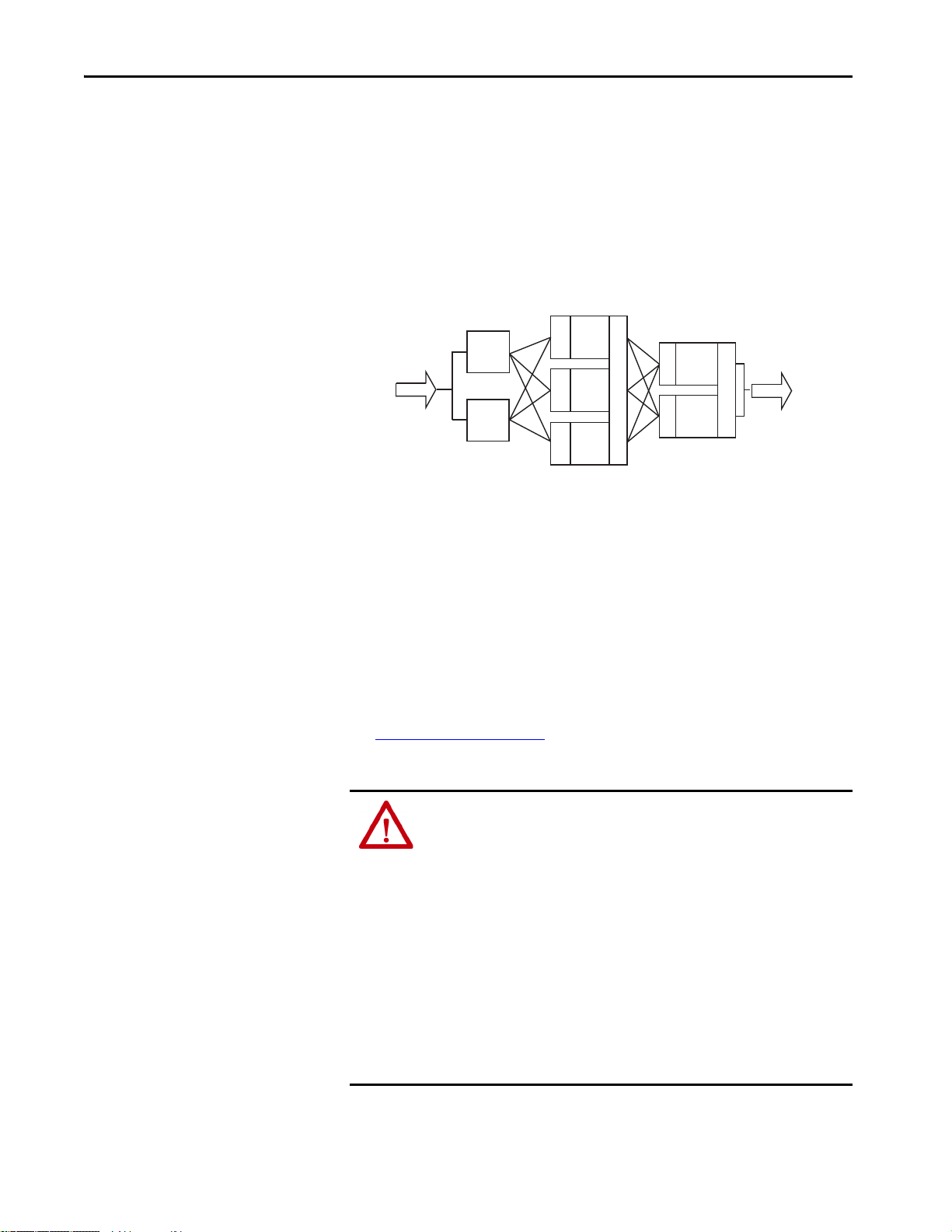
Sensors
I/P
A
CPU
A
CPU
B
V
V
O/P
A
Final
Elements
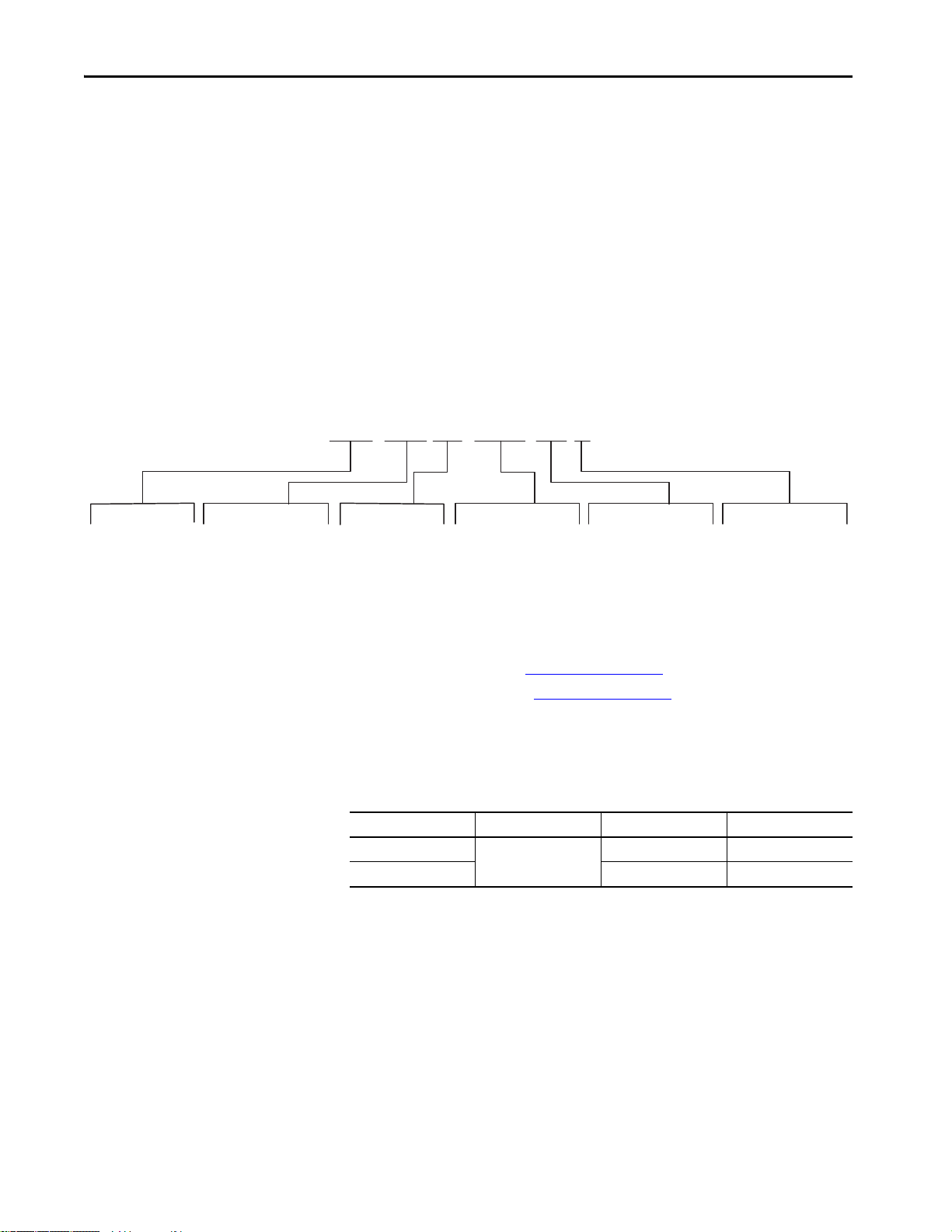
I/P = Input Module
CPU = Processor Modules
O/P = Output Modules
V = Vote
Chapter 1
Introduction
Safety Architecture
The certification authority Technischer Überwachungs-Verein (TÜV)
independently certifies that the AADvance control system meets the
requirements of IEC 61508 SIL 3.
The OptiSIS solution is designed and implemented in accordance with the
requirements of the AADvance Controller Safety Manual, publication
ICSTT-RM446
certifications.
The OptiSIS solution is available in both Fail-safe and Fault Tolerant
configurations.
. See the AADvance Controllers Safety Manual for
ATTENTION: Personnel responsible for deploying a Process Safety solution
must verify that the SIS is tested against the Safety Requirements
Specification (SRS) before the introduction of Hazardous materials into the
Process.
ATTENTION: The Safety Architecture defines how the system behaves under
fault conditions. The correct architecture must be selected based on the
requirements that are defined in the SRS.
Fail-safe System
The Fail-safe architecture option means that the failure of a channel or module
can degrade the applied safety integrity level, or can result in the loss of
function where the Fail-safe system brings the process to the safe state.
The actual behavior under fault conditions is also dependent on configuration
options.
Figure 1 - Fail-safe System
AB PLCs
Rockwell Automation Publication 1711-UM004B-EN-P - September 2016 13
Page 14
Chapter 1 Safety Requirements
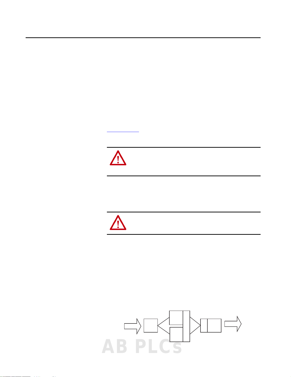
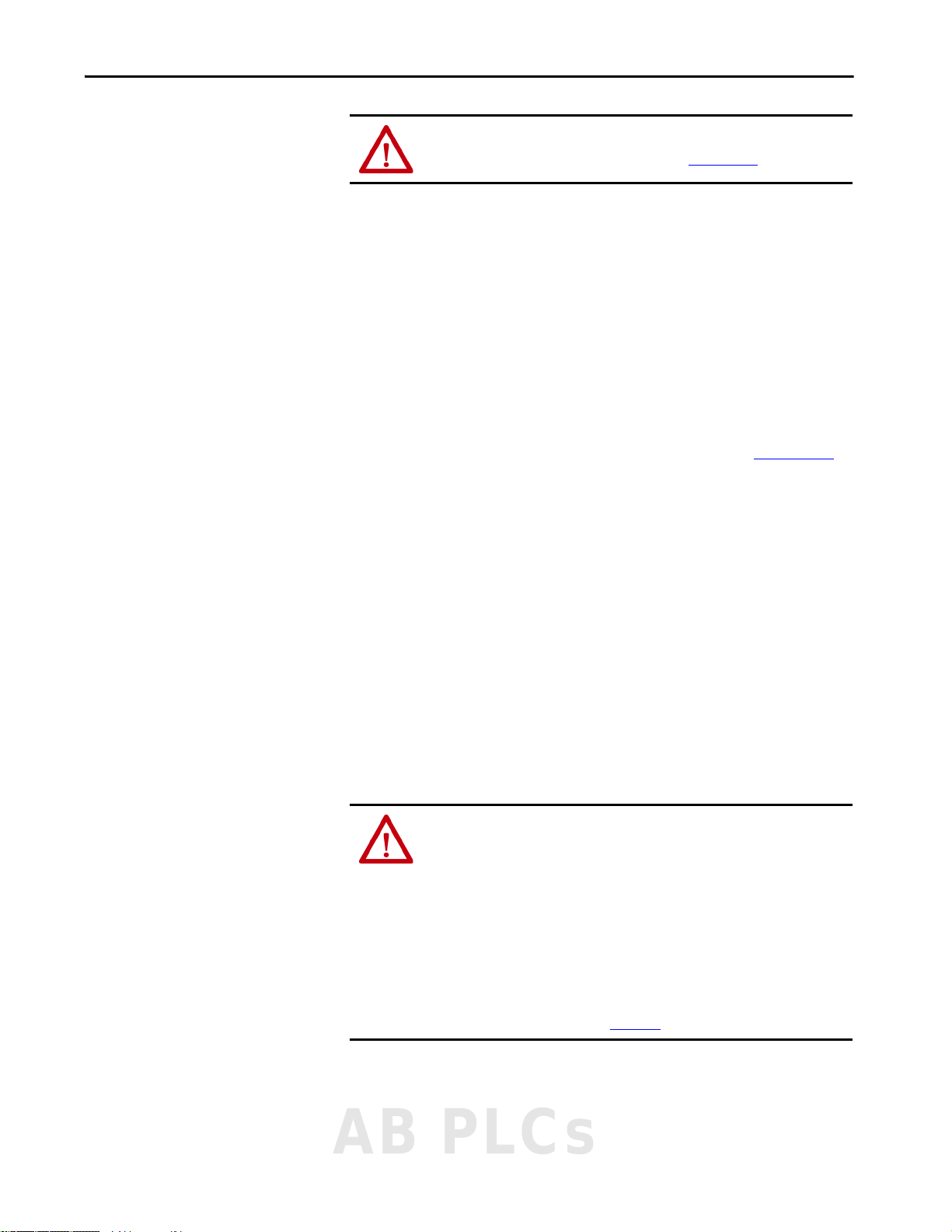
Sensors
Final
Elements
I/P
A
I/P
B
CPU
A
CPU
B
CPU
C
V
V
V
V
V
V
V
O/P
A
O/P
B
I/P = Input Module
CPU = Processor Modules
O/P = Output Modules
V = Vote
Fault Tolerant System
The Fault Tolerant architecture option means that the failure of a channel or
module does not degrade the applied safety integrity level, or result in the loss
of function and the resulting taking the process to the safe state.
The actual behavior under fault conditions is also dependent on configuration
options.
Figure 2 - Fault Tolerant System
Safe State
The internal configuration of the AADvance system that is used in the
OptiSIS solution is that the safe-state is OFF (de-energize-to-action).
De-energize-to-action is the state that an input or output assumes during a
channel or module failure. The OptiSIS solution does however, let you
configure digital inputs and digital outputs to operate in either a normally
energized (de-energize-to-action) or a normally de-energized (energize-toaction).
See Configure I/O on page 47
state.
ATTENTION: Use Energize-to-action configurations only if the following
conditions apply:
• At least two independent power sources to the OptiSIS solution panel must
be used.
• At least one of the power feeds to the panel must be a secure power source
(for example, a UPS or a battery). The power supply hold-up time must
provide power for long enough to bring the process to a safe state.
• OptiSIS solution power supplies generate an alarm when power is lost
(either due to power feed failure or PSU failure). Any power failure alarm
must be responded to and rectified within the mean time to restoration
(MTTR).
• For SIL 3 and high demand energize-to-action applications, the Fault
Tolerant option must be used.
for the configuration of the normal operating
14 Rockwell Automation Publication 1711-UM004B-EN-P - September 2016
Page 15
Safety Requirements Chapter 1
Process Safety Lifecycle, Functional Testing, and Validation
Safety Data
ATTENTION: Follow the Process Safety Lifecycle as described in the
AADvance Controller Safety Manual, publication ICSTT-RM446
Before putting the system into operation, perform a pre-startup acceptance
test (PSAT) which is a functional test of the safety instrumented system (SIS).
The PSAT must be a documented and recorded test procedure that includes
(but is not limited to) the following:
• All power, signal, and ground wiring is checked and secure.
• All input/output loops are functionally exercised through their entire
operating range (including field device calibration).
• All safety functions are tested, including timing properties.
• All functions such as bypasses, alarms, and communication interfaces
(where appropriate) are tested and recorded.
It is recommended to evaluate your PSAT with the checklist in Appendix D
This evaluation helps you to meet safety requirements for the OptiSIS
solution.
The OptiSIS solution has a process safety time (PST) of 1.5 seconds. The PST
brings the system to its safe state (off ) in the event a dangerous fault is
detected. The PST of the safety functions the SIS performs should be equal to,
or less than, the OptiSIS PST of 1.5 seconds. This value is not configurable in
the standard system.
.
.
Mean time to restoration (MTTR) is the maximum allowed time between the
occurrence of a failure and the completion of the repair of that failure, to
maintain the assigned safety integrity level. The allowed time includes the time
to detect the failure, initiate the repair, and fully complete the repair. This
configurable parameter has a range of 0…168 hours (no decimals).
ATTENTION:
• Faulty output modules in a dual configuration that is used in energize to trip
applications must be replaced within the MTTR to maintain SIL 3
performance.
• Faulty processors in a dual configuration must be replaced within the MTTR
to maintain SIL 3 performance.
• The MTTR timer is provided in the human machine interface (HMI). You can
configure the MTTR time according to your SIL level from the System Status
display when you are logged in as the Engineer user in the HMI. If you want
to maintain SIL 3 performance, act on the timer alarm. For more information
on Maintenance displays, see Chapter 8
.
AB PLCs
Rockwell Automation Publication 1711-UM004B-EN-P - September 2016 15
Page 16

Chapter 1 Safety Requirements
PFD/PFH Data
Reliability, PFD, and PFH data is published in the PFHavg and PFDavg Data
for AADvance Controllers, publication ICSTT-RM449
.
Password Protection
The HMI has a security model that is built in to restrict access to specific
functions. The model relies on user roles as defined in this table. The password
is case-sensitive.
ATTENTION: For security reasons, we recommend that you change the
default passwords.
Table 2 - HMI User Roles and Passwords
User Role Default
Default (not logged in)
Operator operator X
Supervisor supervisor X X
Maintenance maintenance X X X
Engineer engineer X X X X
Administrator administrator
RA Administrator raadmin X X X X X X
(1) For HMI version B10 and earlier, the password for Administrator is pass word.
Passwor d
Force I/O
Apply Configurations
Acknowledge/Reset Alarms
Remove Suppress and Force
(1)
XX X XX
Access Diagnostic Functions
Suppress I/O
Shutdown System
Table 3 - Windows User Passwords
User Password
Administrator 1ADMINISTRATOR
Operator 1OPERATOR
The Windows Administrator has complete control over the industrial personal
computer. They can change settings and access the files and programs that are
stored in the personal computer.
Operator has limited control over the industrial personal computer and its
intended purpose is to execute the OptiSIS solution application.
See Application Accounts on page 42
16 Rockwell Automation Publication 1711-UM004B-EN-P - September 2016
for login and password information.
Page 17
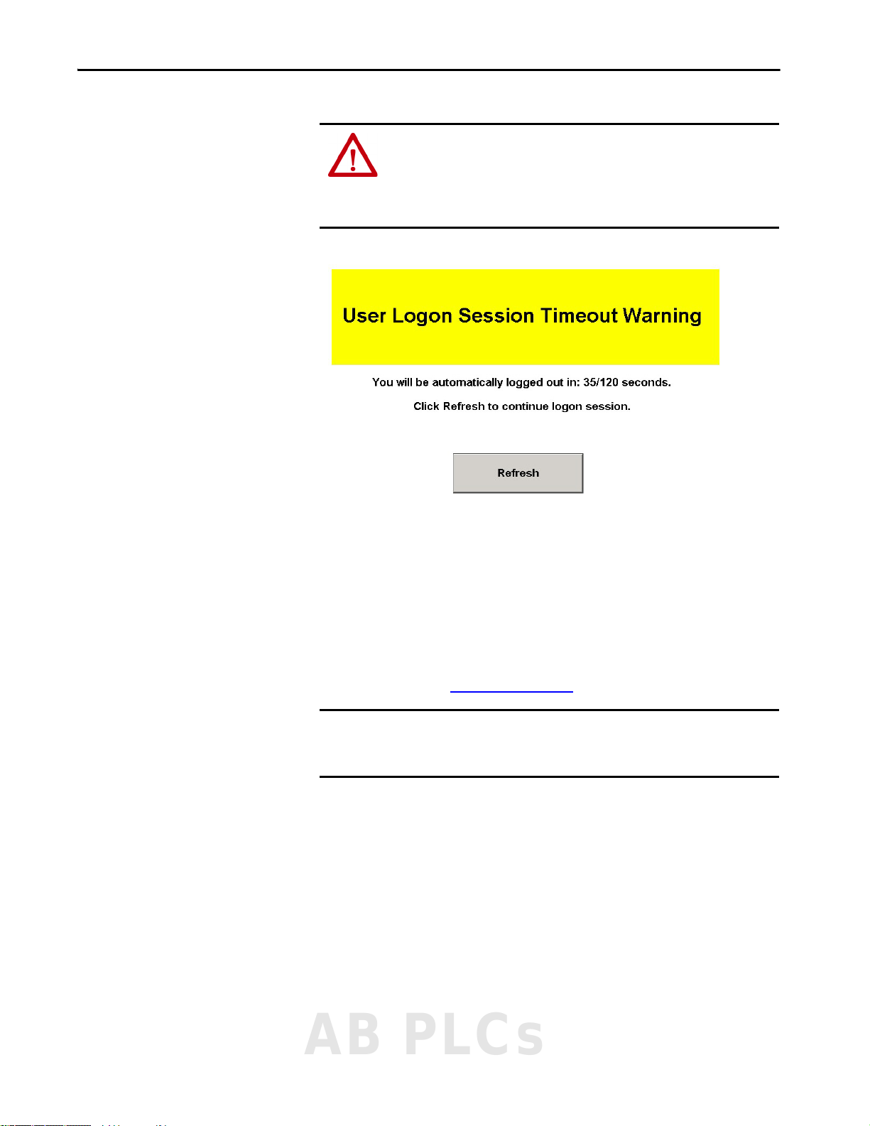
ATTENTION: The OptiSIS has an auto-logout feature. The User Logon Session
Timeout Warning display automatically appears after 20 minutes of
inactivity and lets you refresh the application before completing the
automatic log-off process. All users are automatically logged off after 20
minutes of inactivity to Default.
Figure 3 - User Session Timeout Warning
Safety Requirements Chapter 1
Program Enable Key
The Program Enable Key is a security device that is required to be present in an
OptiSIS solution when applying Rockwell Automation supplied application
and firmware updates. The key is a 9-way 'D' type plug and is supplied with the
processor base unit.
The key must be plugged into the processor base unit to allow upgrades to be
performed. The key is installed if the controller appears in yellow on the
Overview display (see Figure 43 on page 80
IMPORTANT The Program Enable Key is shipped in the base unit. Do not leave the
Program Enable Key in place. Store the key in a safe place with controlled
access.
).
AB PLCs
Rockwell Automation Publication 1711-UM004B-EN-P - September 2016 17
Page 18

Chapter 1 Safety Requirements
Diagnostics
Certification
The AADvance controller embodies sophisticated internal diagnostic systems
to identify faults that develop during operation and raise appropriate alarm and
status indications. The diagnostic systems run automatically and check for
system faults that are associated with the controller (processor and I/O
modules) and field faults that are associated with field I/O circuits. The
internal diagnostics detect and reveal both safe and dangerous failures.
ATTENTION: When the OptiSIS solution is located in a normally unmanned
area, a method for reporting diagnostic alarms into a normally manned area
must be provided to make sure that the defined MTTR is met.
The OptiSIS solution does not carry a specific ‘Product’ certification as it is a
Solution, which is composed of standard products. Each product that is used in
the solution carries specific certifications. To find more information, go to the
Rockwell Automation Product Certification website:
http://www.rockwellautomation.com/global/certification/
Each of the products that are used to create the solution have been installed,
wired, and programmed in accordance with the appropriate user manuals.
Specifically, the AADvance equipment has been designed, installed,
programmed, and tested according to both the AADvance Controller Safety
Manual, publication ICSTT-RM446
phases of IEC61511.
, and following the appropriate lifecycle
18 Rockwell Automation Publication 1711-UM004B-EN-P - September 2016
Page 19
Chapter 2
Installation
This chapter provides basic background information about the solution and
instructions for installation.
ATTENTION: You must use installation and commissioning procedures that
comply with applicable standards of the country of installation. The
applicable standards can include, for example, IEC 61511, NFPA72, and ISA
84.00.01, depending on the location.
ATTENTION: Radio Frequency Interference can influence most electronic
equipment. Exercise caution regarding the use of portable communication
equipment around such equipment. Post signs in the vicinity of the
equipment to provide caution against the use of portable communications
equipment.
Introduction
IMPORTANT These guidelines are not intended to supersede local electrical codes.
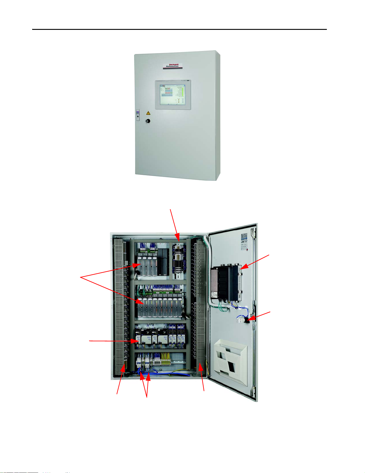
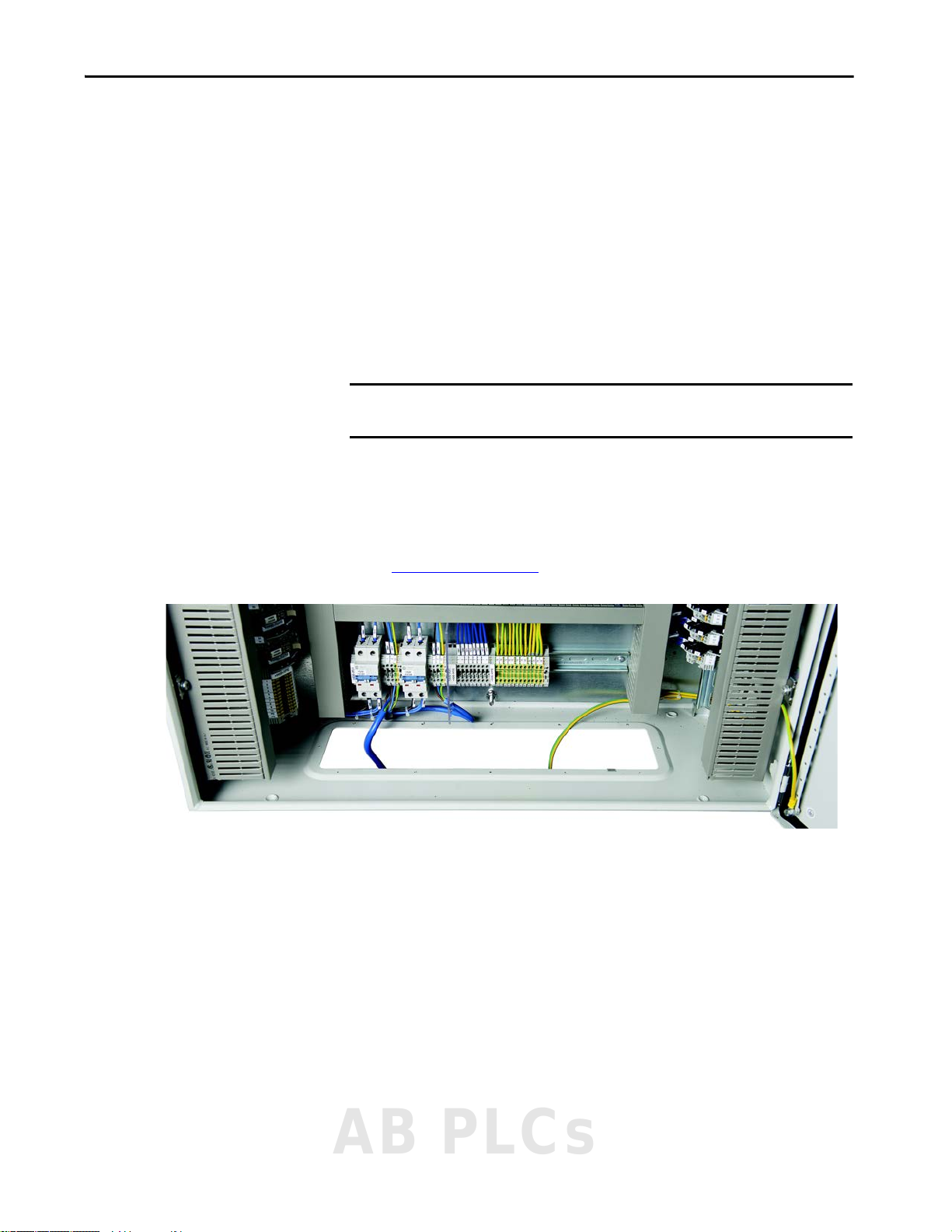
Figure 4, Figure 5, and Figure 6 show the solution and its components:
• AADvance controller CPU
• Flexible inputs (analog/digital)
•Analog outputs
• Digital outputs
•Industrial computer (HMI)
• Enclosure and accessories
AB PLCs
Rockwell Automation Publication 1711-UM004B-EN-P - September 2016 19
Page 20
Chapter 2 Installation
AADvance Controller CPU
and I/O Modules
Industrial Computer
(Mounted on Door)
Power Distribution
Logic Write Keyswitch
(Mounted on Door)
Power Suppli es
Power Feeds
Customer Field Terminals
•Analog Output
•Modbus RTU
• Modbus TCP/IP
• Digital Output
Customer Field Terminals
Flexible Inputs
Figure 4 - OptiSIS Solution – External View
Figure 5 - OptiSIS Solution – Internal View
20 Rockwell Automation Publication 1711-UM004B-EN-P - September 2016
Page 21
Installation Chapter 2
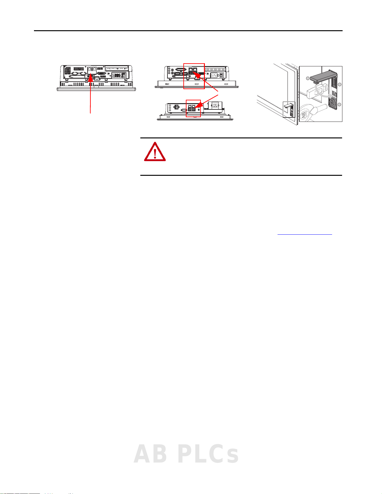
Hinged Door Covering
the USB Ports
6181X Bottom View 6181P Front View6181P Bottom View
USB Ports
Figure 6 - HMI- USB Port Location
ATTENTION: The bottom side USB ports on the 6181X HMI are functionally
hot-pluggable in an environment that is known to be nonhazardous. For
European Zone 2 applications, do not use the USB ports unless the area is
known to be nonhazardous.
All required components are mounted, wired, and installed inside the solution
enclosure.
Installation
The 50 I/O system is contained within a wall-mounted cabinet. The 100 I/O
system is contained within a floor-standing panel. See Table 23 on page 117
enclosure dimensions.
for
Unpack
Before unpacking any items, the packaging must be inspected for damage that
can occur during shipment.
If any packaging is damaged, the package identification marks (such as box
number or crate number) must be noted and communicated to
Rockwell Automation. The package must be stored in a suitable storage area in
the condition it was received. Rockwell Automation then contacts the shipping
agent who can request to inspect the damage. The package must not be opened
without the express written permission of Rockwell Automation.
If packaging is not damaged, the OptiSIS solution must be removed from the
packaging. Verify that all items on packing list are included. If any items are
missing, contact Rockwell Automation.
AB PLCs
Rockwell Automation Publication 1711-UM004B-EN-P - September 2016 21
Page 22

Chapter 2 Installation
Inspection
• Visually inspect the cabinets for mechanical damage. Check the
paintwork for scratches and abrasions.
• Verify that the cabinet door opens and closes and that all latches operate
smoothly.
• Verify that cable assemblies were not damaged during shipment and that
they are appropriately dressed with cable ties and/or spiral wrap.
• Verify that all wire ducts are fitted with covers.
Storage and Operation
Consider the environmental characteristics that are listed in Table 20 on
page 117 when you select the device and the mounting location.
IMPORTANT The standard unit is meant to be installed in a nonhazardous environment.
For additional environmental needs for your SIS, contact your local
Allen-Bradley distributor or Rockwell Automation sales representative.
Wall Mount — 50 I/O Solution
ATTENTION: Crush hazard!
Dropping of the unit can lead to personal injury and/or component damage.
Always support the unit fully during installation; use an assistant.
To mount the 50 I/O OptiSIS solution to the wall, follow these steps.
1. Determine the mounting location and verify that the location is suitable
for the solution by checking the following :
• The site is free from excessive dirt and moisture.
• Sufficient room on all sides of the enclosure is available for the cable
to exit the enclosure and to open the door.
The door swing radius is 800 mm (32 in.) and extends to 110°
without forcing.
22 Rockwell Automation Publication 1711-UM004B-EN-P - September 2016
Page 23
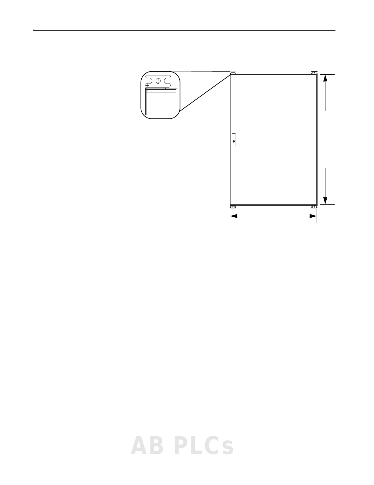
Installation Chapter 2
800 mm (32 in.)
1199 mm (47 in.)
Wal l Mou nt Br acke t
2. Place the enclosure on the wall in the desired location and verify that it is
level.
3. Secure the wall mount bracket.
AB PLCs
Rockwell Automation Publication 1711-UM004B-EN-P - September 2016 23
Page 24
Chapter 2 Installation
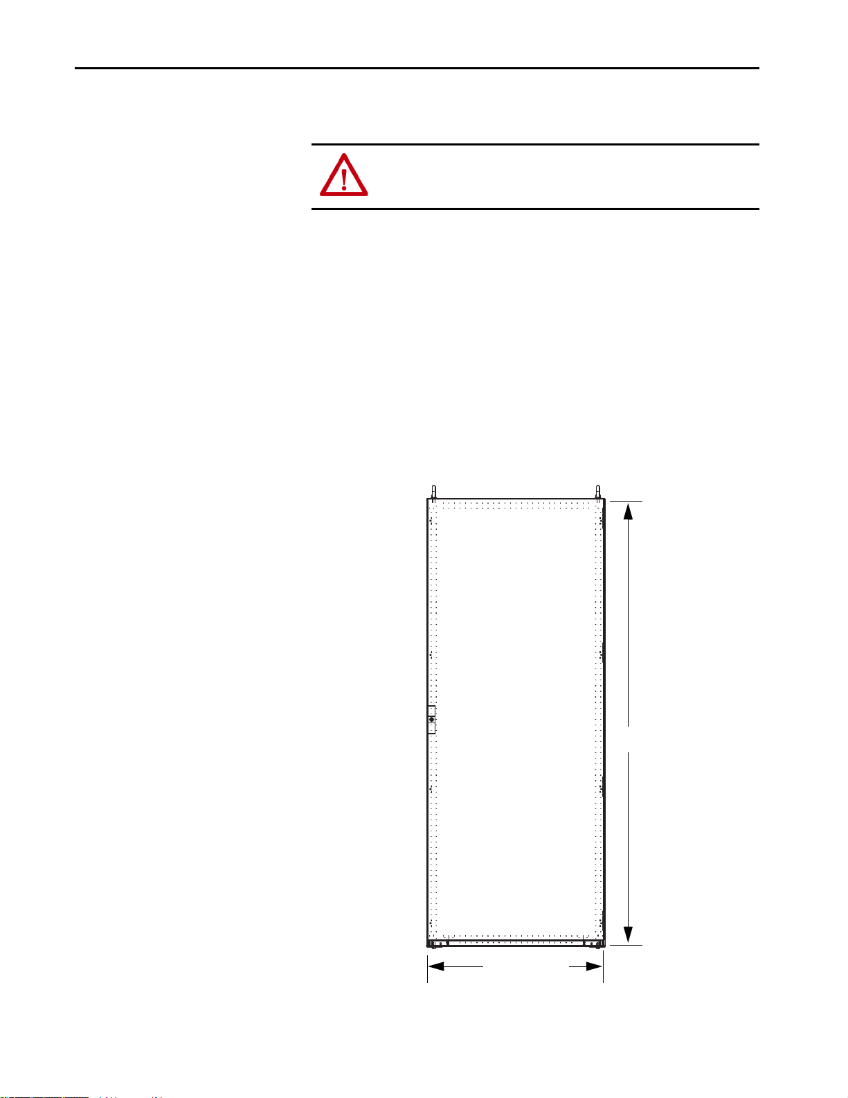
800 mm (32 in.)
2006 mm
(79 in.)
Floor Mount — 100 I/O Solution
ATTENTION: Crush hazard!
Dropping of the unit can lead to personal injury and/or component damage.
Always support the unit fully during installation; use an assistant.
1. Determine the mounting location and verify that the location is suitable
for the solution by checking the following :
• The site is free from excessive dirt and moisture.
• The enclosure stands level after installation.
• Sufficient room on all sides of the enclosure is available for the cable
to exit the enclosure and to open the door.
The door swing radius is 800 mm (32 in.) and extends to 110°
without forcing.
2. Place the enclosure in the position where it is to operate and verify that
the enclosure is level.
Leveling feet allow you to fine-tune the level of the enclosure due to
unevenness at the installation site.
24 Rockwell Automation Publication 1711-UM004B-EN-P - September 2016
Page 25

Connect Power
Chapter 3
Introduction
Power Distribution and Grounding
The OptiSIS solution uses standard Allen-Bradley® power supplies and
redundancy modules. The OptiSIS solution accepts dual power feeds of the
same, or different, voltages. See detailed power distribution drawings for power
details.
IMPORTANT The A and B power feeds do not have to be the same.
IMPORTANT These guidelines are not intended to supersede local electrical codes.
Connect power to terminals shown in the supplied wiring drawings. Terminal
locations are shown in Figure 7
Figure 7 - Terminal Locations
.
AB PLCs
Rockwell Automation Publication 1711-UM004B-EN-P - September 2016 25
Page 26
Chapter 3 Connect Power
There are two ground connections that must be connected before power is
applied to the system.
• The AC safety ground is provided to help protect personnel from
electric shock under fault conditions. Internally, all exposed metal
surfaces, for example, cabinets, racks, and chassis ground connections,
are connected to this termination point.
ATTENTION: The AC Safety Ground must be terminated to a suitable ground.
The recommended/minimum wire size to use for the Protective (Safety)
Earth is 6 mm² (10 AWG).
• The instrument ground is provided to minimize electrical noise for all
DC analog/digital signals. The shields/screens for incoming and
outgoing cables can be connected to the supplied ground termination,
which are internally connected to this point.
Power Cable Types/ Recommendations
Connect to a clean (low noise) ground by using a minimum of 6 mm
2
(10 AWG) conductor.
ATTENTION: Good ground connections must be verified before any work is
conducted. Failure to comply can cause serious injury.
This section includes information about the major issues for proper selection
of cable, and provides recommendations to address these issues. Consider these
conditions and requirements when you choose cable material and construction
for your installation:
• Environment: moisture, temperature, and harsh or corrosive chemicals.
• Mechanical needs: geometry, shielding, flexibility, and crush resistance.
• Electrical characteristics: cable capacitance/charging current, resistance/
voltage drop, current rating, and insulation.
• Safety issues: electrical code requirements, grounding needs, and others.
Choosing incorrect cabling can be costly and can adversely affect the
performance of your installation.
In general, follow these temperature ratings for installations:
Surrounding Air Temperature Recommended Wire
50 °C (122 °F) 90 °C (194 °F)
40 °C (104 °F) 75 °C (167 °F)
The OptiSIS solution is rated for use with 75 °C (167 °F) cable. Cable must be
sized by using the 75 °C (167 °F) column in NEC Table 310.15(B)(16)
(formerly Table 310.16). The temperature rating of the lugs is not relevant.
IMPORTANT The temperature rating of the wire affects the required gauge. Verify that
your installation meets all applicable national, state, and local codes.
26 Rockwell Automation Publication 1711-UM004B-EN-P - September 2016
Page 27
Connect Power Chapter 3
Cable Entry
Verify that cable sizes, wires, and cabinet penetrations for incoming cables are
to local regulations, specifications, and requirements.
Bottom Entry Conduit
Cable entry is through the bottom gland plate (NEMA 4 models only) for
both the 50 I/O and 100 I/O solutions. To route your cable through the
bottom gland plate, follow these steps.
1. Prepare the installation site so the foundation is level.
2. Remove gland plate, drill holes.
IMPORTANT The outdoor NEMA 4X model does not come with a gland plate. Cable entry
locations are placed at the time of installation.
3. Before the OptiSIS solution is installed, place and stub up conduit
approximately 2 in. (51 mm) above floor level and confirm that all
incoming conduit is clear of any internal components.
For approximate section base dimensions and ground bus locations, see
Installation on page 21
shipped with the solution.
, or elevation and floor plan drawings that are
AB PLCs
Rockwell Automation Publication 1711-UM004B-EN-P - September 2016 27
Page 28

Chapter 3 Connect Power
Cable Installation
Verify that cabinet penetrations for incoming cables are to local regulations,
specifications, and requirements. Size cables and wires per local codes,
specifications, and requirements.
The OptiSIS solution is rated for use with 75 °C (167 °F) cable. Cable must be
sized by using the 75 °C (167 °F) column in NEC Table 310.15(B)(16)
(formerly Table 310.16). The temperature rating of the lugs is not relevant.
ATTENTION: Properly connect all line and load cables to avoid a bolted fault
and equipment damage.
Lugs
Follow this procedure to install the lugs. The lug accepts a wire size from
2…50 mm
2
(14…2/0 AWG).
1. Verify the compatibility of wire size, type, and stranding versus the
power lugs furnished.
Use correct lugs in all applications.
Power Layout
2. Crimp compression lugs with manufacturer recommended tools.
3. To verify field wire connection points, use the electrical schematics.
The OptiSIS solution uses standard Allen-Bradley power supplies and
redundancy modules. The system design accommodates dual inputs of
24V DC, 110…240V AC, and/or 110…300V DC.
28 Rockwell Automation Publication 1711-UM004B-EN-P - September 2016
Page 29
Connect Field Wiring
Chapter 4
Grounding Requirements
Input Wiring
IMPORTANT Analog and digital inputs support a signal ground (default) and also provide
a place to terminate a shield/screen to maintain signal quality.
When external field device power is used, it must be kept separate from the
signal wiring to minimize signal noise.
Field input signals are individually referenced to the instrument ground
(OptiSIS Field Power common, 0V), each has a removable link to allow them
to float regarding instrument ground. The recommended/minimum wire size
to use for the instrument ground (on the instrument ground bus bar) is 6 mm2
(10 AWG).
See the Industrial Automation Wiring and Grounding Guidelines, publication
1770-4.1
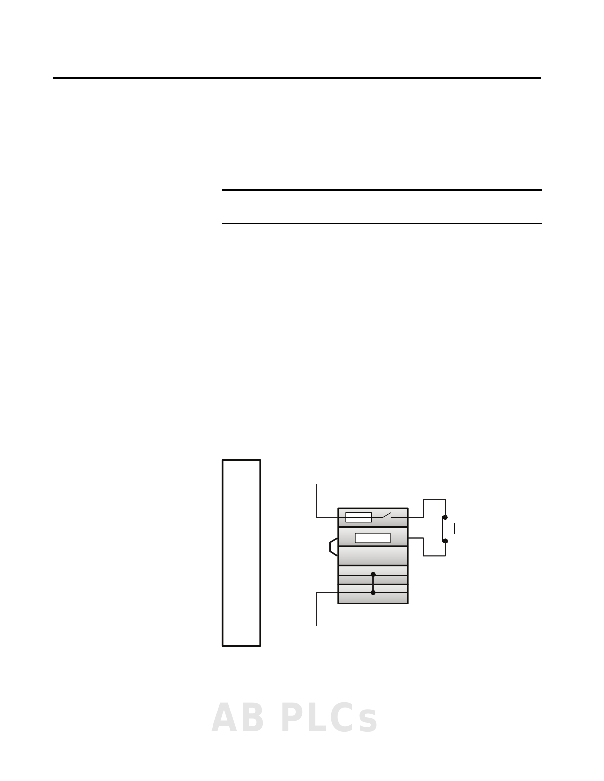
The device type and where the field wire lands determine whether the flexible
inputs can be wired as analog or digital.
Figure 8 - Digital Input (OptiSIS Solution Powered)
Channel
, for additional information.
Input
24V DC
+
–
0V DC
AB PLCs
Rockwell Automation Publication 1711-UM004B-EN-P - September 2016 29
Page 30
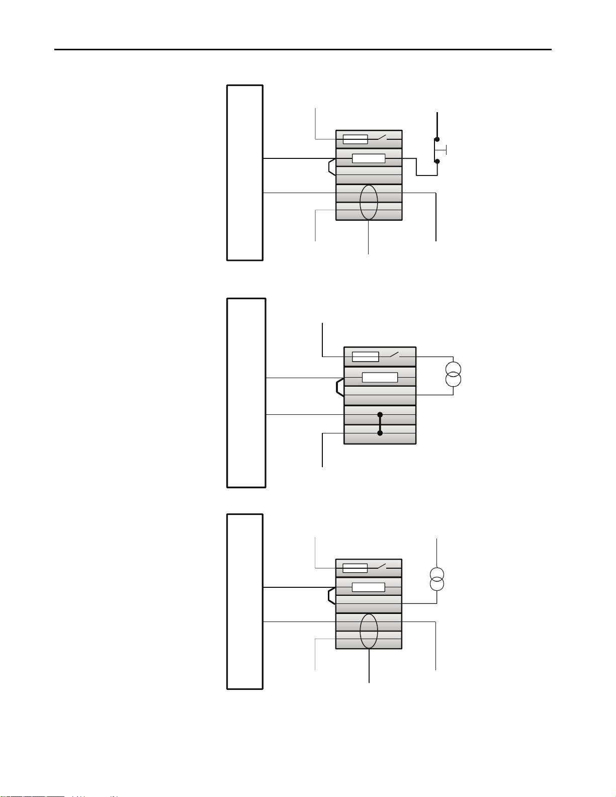
Chapter 4 Connect Field Wiring
24V DC
0V DC
Input
Channel
+
–
24V DC
0V DC
24V DC
0V DC
End-user to remove jumper
Input
Channel
+
–
Figure 9 - Digital Input (Field Powered)
Input
24V DC
Channel
+
–
24V DC
0V DC
End-user to remove jumper
Figure 10 - Analog Input (OptiSIS Solution Powered)
Figure 11 - Analog Input (Field Powered)
0V DC
30 Rockwell Automation Publication 1711-UM004B-EN-P - September 2016
Page 31

Connect Field Wir ing Chapter 4
Device Power
Device Signal
Device Signal/
Power Return
Device Power
Device Signal +
Device Signal –
Device Power Return
Figure 12 - Analog Input (OptiSIS Solution Powered, 3-wire Transmitter)
Input
24V DC
Channel
+
–
0V DC
Figure 13 - Analog Input (OptiSIS Solution Powered, 4-wire Transmitter)
Input
24V DC
Channel
+
–
0V DC
AB PLCs
Rockwell Automation Publication 1711-UM004B-EN-P - September 2016 31
Page 32

Chapter 4 Connect Field Wiring
Device Signal +
Device Signal –
1
0
111223244344
33
34
12
1
DO Power Line
Terminal Block
DO Return Line
Terminal Block
Relay 3 N.O./1 N.C.
Contact s
Diode Block
End Barrier
DO Power Line
DO Return Line
System-consumed
N.C. Contact
System-consumed
N.O. Contact
Customer
N.O. Contact
Customer
N.O. Contact
Analog Output Wiring
Digital and Relay Output Wiring
Figure 14 - Analog Output Wiring
Analog
24V DC
Output
Channel
+
–
0V DC
Figure 15 - Relay Wiring Legend
Load
ATT EN TI ON : System contacts are used to detect failures in the relay output
circuit. Wiring that is associated with these contacts, if modified, results in
32 Rockwell Automation Publication 1711-UM004B-EN-P - September 2016
output fault alarms and reduce safety integrity of the output circuit.
Page 33

Connect Field Wir ing Chapter 4
1
0
111223244344
33
34
Link
Link
Custom er Power
Customer Return
Load
Link
Custom er Power
Customer Return
LoadLoad
1
0
111223244344
33
34
Customer Power
Customer Return
Load
Figure 16 - N.O. Contact for a Normally De-energized Output (Parallel Contacts, Energize to
Trip )
Figure 17 - N.C. Contact for a Normally Energized Output (Series Contacts, De-energize to Trip)
34
33
Figure 18 - 24V DC Powered Digital Output
ATT EN TI ON : External power source must have circuit protection to avoid
exceeding the current rating of the output relay contacts.
0
1
111223244344
Contact Derating
Contact rating is 6 A at 250V AC/30V DC. Derate the maximum continuous
current by 0.1 A for each 1 °C (1.8 °F) above 55 °C (131 °F).
AB PLCs
Rockwell Automation Publication 1711-UM004B-EN-P - September 2016 33
Page 34

Chapter 4 Connect Field Wiring
Notes:
34 Rockwell Automation Publication 1711-UM004B-EN-P - September 2016
Page 35

Startup
Chapter 5
First-time Powerup
Navigation
Follow these steps the first time you apply power to the OptiSIS solution.
1. Switch all circuit breakers to the Off position and open all fuses.
2. Energize the power feed and verify voltage at main incoming terminals.
3. Close each 120V AC circuit breaker one at a time and verify that the
corresponding power supply is energized.
4. Measure the output voltage of the power supply and verify that it is
delivering 24V DC.
5. Close each 24V DC fuse one at a time and verify that the corresponding
equipment receives 24V DC by measuring at the power terminals of the
receiving equipment.
6. Close all 24V DC fuses and check that the system powers up as
expected.
The HMI application facilitates user navigation through a centralized icon
toolbar. The following are the main displays:
• Operator
•Maintenance
• Alarm
•Warning
•Help
Each main display contains at least one page, where pages are equivalent to
displays. To access a particular display, press the corresponding icon.
AB PLCs
Rockwell Automation Publication 1711-UM004B-EN-P - September 2016 35
Page 36

Chapter 5 Startup
Maintenance
Display
(Controller)
IO
Confi
Password
Control
Confi
Load/Save
Navigation
Operation
Commands
Alarms /
Warnings
Alarm
Display
Warning
Display
Help Screen
(Info)
Maintenance/
Security
Blank
Cause & Eect 5
Display
Cause & Eect 9
Display
Cause & Eect 8
Display
Cause & Eect 7
Display
Cause & Eect 6
Display
Cause & Eect 2
Display
Cause & Eect 3
Display
Cause & Eect 4
Display
Cause & Eect 10
Display
Cause & Eect 1
Display
IO Confi
Faceplates
IO Confi
Overlay
Module
Faceplates
LEGEND
System Home Screen
Screen can navigate directly
to top-level screens
Screen can NOT navigate directly
to top-level screens
Faceplates (popups)
MAIN ICON
TOOLBAR
Navigation (on-screen object)
Navigation
(Navigation / arrows)
Operator
Display
(Overview)
For simple and quick navigation, you can access and progress through multiple
pages of a display by pressing the arrows at the bottom of the display. Notice
the green dot at the center bottom of each display for orientation. Navigation
arrows are available on most displays and loop at end of sequence.
Figure 19 - Navigation Arrows and Page Dots
Figure 20 is a navigational hierarchy structure of the basic displays.
Figure 20 - HMI Displays Navigational Hierarchy Structure
36 Rockwell Automation Publication 1711-UM004B-EN-P - September 2016
Page 37

Startup Chapter 5
Operator
The Operator display is the first display that appears. You can access and
progress through the Cause and Effect charts by pressing the arrows at the
bottom of the display. You can also press a specific chart navigation button to
go to that Cause and Effect chart.
Figure 21 - Operator Display
Figure 22 - Cause and Effect Chart - Online Mode
Figure 23 - Cause and Effect Chart - Configuration Mode
AB PLCs
Rockwell Automation Publication 1711-UM004B-EN-P - September 2016 37
Page 38

Chapter 5 Startup
Maintenance
This Maintenance display has four pages. Access and progress through multiple
pages of a display by pressing the arrows at the bottom of the display.
Figure 24 - Maintenance Display – System Status
Figure 25 - Maintenance Display – I/O Configuration
Figure 26 - Maintenance Display – User Accounts
38 Rockwell Automation Publication 1711-UM004B-EN-P - September 2016
Page 39

Figure 27 - Maintenance Display – Configuration Load/Save
Alarm
Use the Alarm display to view the unit alarms.
Startup Chapter 5
Figure 28 - Alarm Display
AB PLCs
Rockwell Automation Publication 1711-UM004B-EN-P - September 2016 39
Page 40

Chapter 5 Startup
1
2
Warning
Use the Warning display to view a listing of all unit warnings.
• Level 1 Warnings: Conditions are preventing unit operation.
• Level 2 Warnings: Unit functions are disabled or bypassed. These
include suppressed alarms and trips, forced inputs, and forced outputs.
Figure 29 - Warning Display
Help
The Help display has five pages. You can progress through the pages of the
Help display by pressing the arrows at the bottom of the display. The Help
display pages provide information regarding application information, screen
navigation, logic functions, color keys for system icons, and more.
Figure 30 - Help Display – Application Information
Item Description
1 HMI Version - Current version of the OptiSIS HMI application.
PLC Version - Current version of the OptiSIS controller application.
2 Config CRC - Error-checking code configured in the OptiSIS HMI application. This value must match the
Running CRC.
Running CRC - Error-checking code running in the OptiSIS controller application. This value must match the
Config CRC.
40 Rockwell Automation Publication 1711-UM004B-EN-P - September 2016
Page 41

Startup Chapter 5
Figure 31 - Help Display – Screen Navigation and Logic Functions
Figure 32 - Help Display – Alarm, Warning, Maintenance, and Security Symbols
Connect Peripherals
You can connect peripherals, such as a keyboard and mouse, to the
corresponding USB ports on the bottom side of the HMI. The USB ports are
covered by a hinged door. See Figure 6 on page 21
ATTENTION: The bottom side USB ports on the 6181X HMI are functionally
hot-pluggable in an environment that is known to be nonhazardous. For
European Zone 2 applications, do not use the USB ports unless the area is
known to be nonhazardous.
.
AB PLCs
Rockwell Automation Publication 1711-UM004B-EN-P - September 2016 41
Page 42

Chapter 5 Startup
Application Accounts
The OptiSIS solution initially loads and is operational without logging in. On
load, the initial user account is ‘Default’.
TIP On the main icon toolbar, the Current User is listed.
See Configure User Accounts on page 44
your password. The user roles are defined in Tabl e 2 o n pa ge 16
To change your current user login, follow these steps.
1. To navigate to the Operator display, press .
The Operator display appears.
2. To log in, press .
The Login dialog box appears.
for instructions on how to change
.
3. Press in the User name field.
A keyboard appears.
42 Rockwell Automation Publication 1711-UM004B-EN-P - September 2016
Page 43

4. Type the User name and press Enter on the keyboard.
The keyboard disappears.
TIP User names are not case-sensitive.
5. Press in the Password field.
A keyboard appears.
6. Type the Password and press Enter on the keyboard.
The keyboard disappears.
TIP Passwords are case-sensitive.
7. Press OK.
Startup Chapter 5
If the User name and password are incorrect, an error appears.
TIP You are allowed unlimited login attempts.
If you entered your account information correctly, the current user name
appears in the header.
AB PLCs
Rockwell Automation Publication 1711-UM004B-EN-P - September 2016 43
Page 44
Chapter 5 Startup
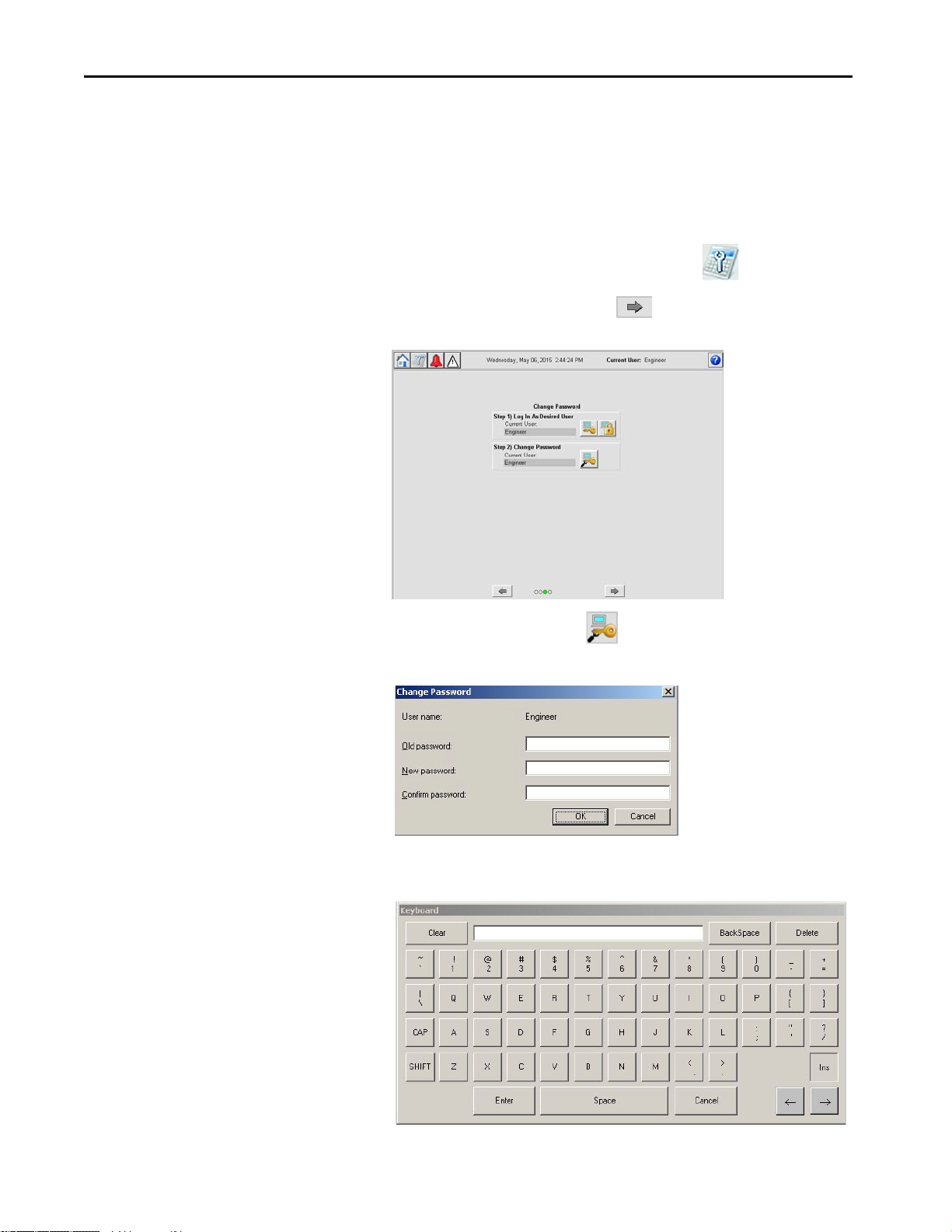
Configure User Accounts
The HMI application has default user account information, however, it is
possible to change the password for a specific user role. To update the
password, follow these steps.
1. Navigate to the Maintenance display by pressing .
2. On the Maintenance display, press until you reach the User
Accounts display.
3. To change the password, press .
The Change Password dialog box appears.
4. Press the Old password field.
A keyboard appears.
44 Rockwell Automation Publication 1711-UM004B-EN-P - September 2016
Page 45
Startup Chapter 5
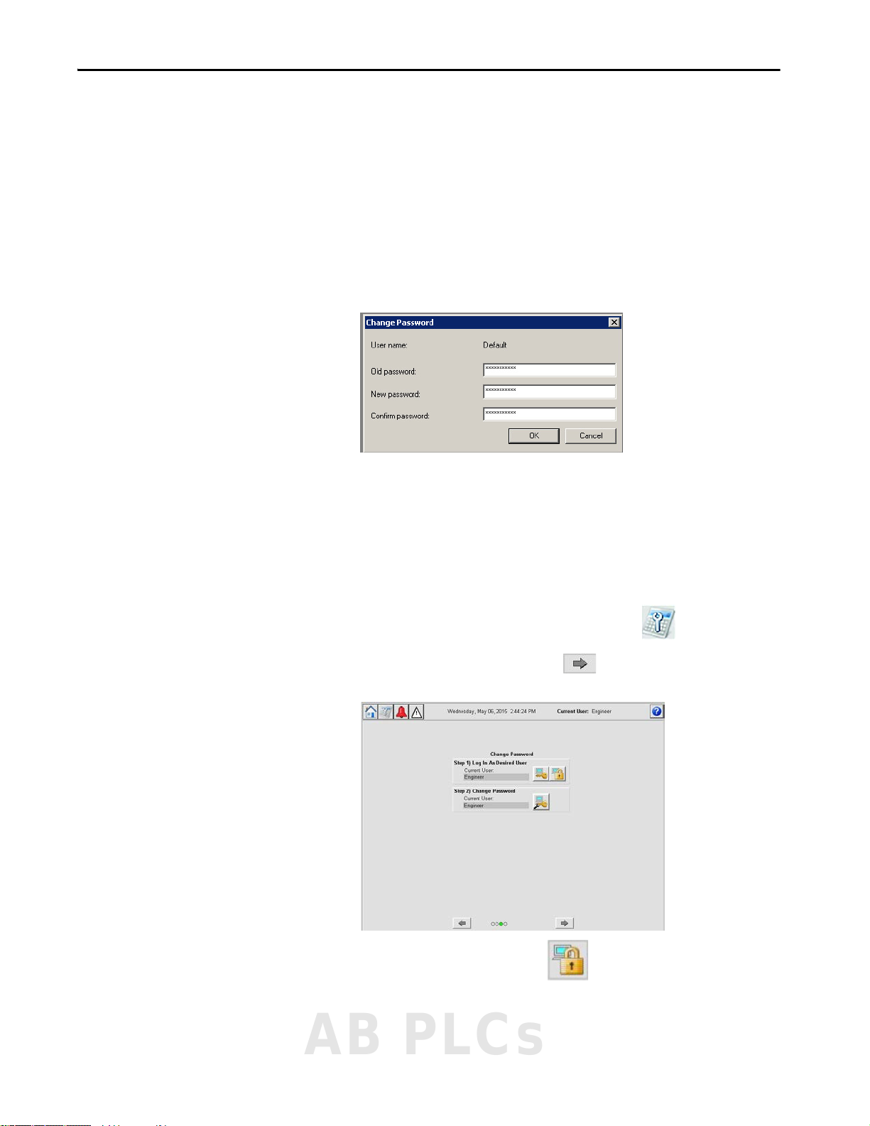
5. Type the old password and press Enter on the keyboard.
6. Press the New password field.
A keyboard appears.
7. Type the new password and press Enter on the keyboard.
8. Press the Confirm password field.
A keyboard appears.
9. Type the new password again and press Enter on the keyboard.
10. To confirm the password change, press OK.
Log Out Current User
To help prevent unauthorized access to your system, we recommend that you
log out when you are done working with the system. To log out of a user
account, follow these steps.
1. Navigate to the Maintenance display by pressing .
2. On the Maintenance display, press until you reach the User
Accounts display.
3. To log off the current user, press .
4. The Current User in the header reverts to Default.
AB PLCs
Rockwell Automation Publication 1711-UM004B-EN-P - September 2016 45
Page 46

Chapter 5 Startup
Notes:
46 Rockwell Automation Publication 1711-UM004B-EN-P - September 2016
Page 47

Configure I/O
ATTENTION: If I/O configuration or Cause and Effect logic changes are
performed while process is operational (online changes), then a formal
Management of Change (MOC) process must be followed. The process
includes, but is not limited to, an impact analysis of the change, documented
implementation and test procedures, and identification of any additional
measures that are required while the change is made.
Chapter 6
Configure I/O Points
Table 4 - Configuration Parameters
Category Item Data Type Description
Input Conditioning Channel Enabled Boolean Channel enabled: 0 = disabled, 1 = enabled
Description String Device description
Tag Nam e St rin g Ta g na me
Channel Type Boolean Input mode: 0 = digital input, 1 = analog input
Switching Level Real Digital switching level value (V) [Range = 0…23V (digital only)]
Input Sense Boolean Digital input sense: 0 = normally closed, 1 = normally open (digital input only)
Line Monitoring Fitted Boolean Monitored DI: 0 = not monitored, 1 = line monitored (digital input only)
Units String Process variable engineering units (analog input only)
Maximum PV Real Process variable maximum value [Range = -999999.9…999999.9 (analog input only)]
Minimum PV Real Process variable minimum value [Range = -999999.9…999999.9 (analog input only)]
Alarm Unlatched Boolean Unlatch alarms: 0 = latched, 1 = not latched
Alarm on Fault Boolean Alarms on fault: 0 = no alarm on fault, 1 = alarm on fault
Alarm Enable 4x Boolean (1 per analog alarm) Analog alarm enabled: 0 = disabled, 1 = enabled
Alarm Limits 4x Real (1 per analog alarm) Analog alarm limit value (EU)
Digital Output
Conditioning
Channel Enabled Boolean Channel enabled: 0 = disabled, 1 = enabled
Description String Device description
Tag Nam e St rin g Ta g na me
Output Sense Boolean Digital output sense: 0 = normally de-energized, 1 = normally energized
Unlatch Output Boolean Output latch type: 0 = latched, 1 = not latched
Configuration parameters are accessible on the HMI or by using the offline
configuration tool (Appendix A
Configuration parameters consist of the following items.
on page 103) for initial development.
AB PLCs
Rockwell Automation Publication 1711-UM004B-EN-P - September 2016 47
Page 48

Chapter 6 Config ure I/O
7
6
12345
Item Description
1 Flexible inputs
2 Digital outputs
3Analog outputs
4 Internal paramete rs
5 Modbus inputs
6 Online/Configuration mode indicator
7 Online/Configuration toggle
Table 4 - Configuration Parameters
Category Item Data Type Description
Analog Output
Conditioning
Internal Parameters Description String Description
Modbus Inputs Description String Description
Channel Enabled Boolean Channel enabled: 0 = disabled, 1 = enabled
Description String Device description
Tag Nam e St rin g Ta g na me
Channel Type Boolean Analog output mode: 0 = AI repeat, 1 = Cause and Effect output
AI Repeat DINT AI channel to repeat
High Current Real High current value (mA), max 20 mA
Low Current Real Low current value (mA), min 0 mA
Output Sense Boolean Digital output sense: 0 = normally de-energized, 1 = normally energized
Tag Nam e St rin g Ta g na me
Tag Nam e St rin g Ta g na me
Figure 33 shows the I/O configuration display. The display shows a
representation of each I/O card and its channels. The channels are either green
to indicate that the channel configuration matches the runtime configuration,
or yellow to indicate that there is a difference between the configured I/O and
the runtime I/O. The Online/Configuration mode indicator shows if you are
in Online mode (view current controller variables) or Configuration mode
(configure then download configuration).
The configuration display is used to Enable, Disable, and Edit Channels.
When you press on the colored box to the right of the channel number, the
configuration display appears. Each configuration display is described later in
the chapter (starting on page 52
).
Users with a role other than Engineer can view status, but cannot edit the I/O
configuration.
Figure 33 - I/O Configuration Display
48 Rockwell Automation Publication 1711-UM004B-EN-P - September 2016
Page 49

Configure I/O Chapter 6
Configure an I/O
IMPORTANT To configure your I/O with the Offline Configuration Tool, see Appendix A
These steps explain how to configure the fundamental characteristics for an
input, output, internal parameter, or Modbus input.
TIP You must be in Configuration mode to change characteristics.
IMPORTANT Internal parameters and Modbus inputs are enabled by default and are
selectable by the Cause and Effect charts. Modbus inputs are the only
parameters that can be written through Modbus.
1. Log in as Engineer.
See Application Accounts on page 42
2. To go to the Maintenance display, press .
3. From the Maintenance display, press until the I/O configuration
display appears.
4. To configure the I/O, press .
for login procedure.
.
The I/O Configuration display appears.
AB PLCs
Rockwell Automation Publication 1711-UM004B-EN-P - September 2016 49
Page 50

Chapter 6 Config ure I/O
5. To configure a particular channel, press the channel.
A configuration faceplate opens.
6. To enable the channel, check Channel Enabled.
IMPORTANT If Channel Enabled is not selected, then all other parameters are not seen.
Checking and clearing Channel Enable causes parameters to revert to a
default state.
50 Rockwell Automation Publication 1711-UM004B-EN-P - September 2016
Page 51

Configure I/O Chapter 6
I/O Configuration
Modbus Input Configuration Internal Parameters Configuration
7. To configure a channel, follow these steps.
a. Press in the description field.
A keyboard appears.
IMPORTANT The keyboard is a standard FactoryTalk® keyboard. Update Field is not
configured for use in the OptiSIS solution. Press Enter to store parameter
values.
b. Type a description (maximum length 40 characters).
c. Press Enter on the keyboard.
IMPORTANT For internal parameters and Modbus inputs, no further configuration is
The keyboard disappears. The field updates with the description.
d. Repeat this process for Tag Name (maximum length 20 characters).
8. Continue to:
• Configure Analog Input Characteristics
• Configure Digital Input Characteristics
• Configure Analog Output Characteristics
• Configure Digital Output Characteristics.
AB PLCs
Rockwell Automation Publication 1711-UM004B-EN-P - September 2016 51
needed.
Page 52

Chapter 6 Config ure I/O
6
7
8
9
10
12
1 2
4
5
3
11
Configure Analog Input Characteristics
After the input is created by enabling the channel, entering a description, and
naming the tag, you can configure the characteristics of the analog input.
TIP Unconfigured points return a tag name of 'DISABLED' and a description of
'Spare Channel’. The tag name and descriptions reside in the HMI only.
Figure 34 - Analog Input Configuration Faceplates
Item Description
1 Device Configuration tab.
2 Channel Enabled - This feature controls the channel parameters configuration.
3 Description (maximum length 40 characters) - The description is shown in the Module Type faceplate to
describe the channel. Be descriptive for quick navigation and selection.
4 Tag Name (maximum length 20 characters) - The tag name is used in the Module Type faceplate to identify
the channel. Use field device names for Cause and Effect selection/presentation.
5 Channel Type (Analog or Digital) - The Flexible Input channel can be wired to either an analog input or
digital input (page 56
6 Process Variable (PV) Minimum/Maximum - Input process variable maximum and minimum value settings
in engineering units, as corresponding to 20 mA and 4 mA respectively (range = -999999.9…999999.9).
7 Units (maximum length 6 charac ters) - Engineering units relevant to the input that is configured (for
example, barg, degC, degF, %LEL, ppm).
8 Alarm Configuration tab.
9 Alarm Unlatched - With this box cleared, any configured input alarm latches when the alarm occurs. To
unlatch, the input first has to return to a normal value and then be reset (either by the HMI or by the
external Modbus Rese t being toggled to 1).
With this box checked, the analog input or digital input alarm resets once the input is at a normal value.
10 Alarm on Fault - With this box cleared, a field or module fault does not cause the input to generate any trip
alarms (although faults are still reported).
With this box checked, a field or module fault generates all trip alarms for the inputs affected.
11 Enable Alarms (High High, High, Low, and Low Low) - Enables (box checked)/disables (box cleared) the
selected alarm for the analog input.
12 Limits (High High, High, Low, and Low Low) - Configure the required alarm limits, within the configured
maximum and minimum process variable values, as defined on the Device Configuration tab.
). Required subparameters vary according to the option you choose here.
52 Rockwell Automation Publication 1711-UM004B-EN-P - September 2016
Page 53

To configure the analog input, follow these steps.
1. In Channel Type, press Analog Input.
The analog input characteristics appear.
2. Configure the values for the analog input settings.
TIP Input Process Variable maximum and minimum settings correspond to
20 mA and 4 mA respectively.
a. Press in the Maximum PV field.
A numeric keypad appears.
Configure I/O Chapter 6
b. Enter a value by using the keypad.
c. Press Download.
d. Repeat steps a
e. Press in the Units field.
A keyboard appears.
f. Enter the units.
g. Press Enter on the keyboard.
3. To open the Alarm configuration tab, press .
…c for Minimum PV.
AB PLCs
Rockwell Automation Publication 1711-UM004B-EN-P - September 2016 53
Page 54

Chapter 6 Config ure I/O
4. Configure the Alarm Unlatched and Alarm On Fault settings as
required by pressing the required checkboxes.
5. To set the limit values for the alarms, follow these steps.
IMPORTANT You have to check an Alarm Enable box first before setting a limit value.
Four limits are available (High High, High, Low, and Low Low) to be
used in your specific installation. These instructions describe how to
configure one of these limits.
a. Under Enable, press the High High checkbox.
A green check mark and Limits field appear.
b. Press the High High Limits field.
A keypad appears.
c. Enter the limit.
d. Press Download.
The keypad disappears.
6. To close the configuration faceplate, press .
54 Rockwell Automation Publication 1711-UM004B-EN-P - September 2016
Page 55

Configure I/O Chapter 6
7. To make your changes to the controller, you can download configuration
by using the logic write keyswitch at the front of the panel.
IMPORTANT On the I/O configuration display, the I/O channels that you configured or
changed appear as yellow. The yellow box indicates that there are
differences between what you configured and what the controller is
running.
AB PLCs
Rockwell Automation Publication 1711-UM004B-EN-P - September 2016 55
Page 56

Chapter 6 Config ure I/O
8
9
10
6
7
1
5
4
3
2
11
Configure Digital Input Characteristics
After the input is created by enabling the channel, entering a description, and
naming the tag, you can configure the digital input characteristics.
TIP Unconfigured points return a tag name of 'DISABLED' and a description of
'Spare Channel’. The tag name and descriptions reside in the HMI only.
Figure 35 - Digital Input Configuration Faceplates
Item Description
1 Device Configuration tab.
2 Channel Enabled - This feature controls the channel parameters configuration.
3 Description (maximum length 40 characters) - The description is shown in the Module Type faceplate to
describe the channel. Be descriptive for quick navigation and selection.
4 Tag Name (maximum length 20 characters) - The tag name is used in the Module Type faceplate to identify
the channel. Use field device names for Cause and Effect selection/presentation.
5 Channel Type (Analog or Digital) - The Flexible Input channel can be wired to either an analog input
6 Switching Level (V) - The level across which the input is deemed to be energized (above this value) or
7 Input Sense (Normally Open or Normally Closed) - Normal state of the field switch.
8 Line Monitoring Fitted - Check this box for line monitored switches/devices with End-of-Line (EOL)
9 Alarm Configuration tab.
10 Alarm Unlatched - With this box cleared, any configured digital input alarm latches when the alarm occu rs.
11 Alarm on Fault - With this box cleared, a field or module fault does not cause the input to generate any trip
) or digital input. Required subparameters vary according to the option you choose here.
(page 52
de-energized (below this value). Typically the default value (8.96V) is sufficient. (min 0V, max 23V)
resistors installed. Clear this box for non-line monitored devices.
With this box cleared, open circuit and short circuit faults are not generated.
With this box checked, open circuit and short circuit faults are generated.
To unlatch, the input first has to return to a normal value and then be reset (either by the HMI or by the
external Modbus Reset being toggled to 1).
With this box checked, the digital input alarm resets once the input is at a normal value.
alarms (although faults are still reported).
With this box checked, a field or module fault generates the configured trip alarm for the digital input.
56 Rockwell Automation Publication 1711-UM004B-EN-P - September 2016
Page 57

Configure I/O Chapter 6
To configure the digital input, follow these steps.
1. In Channel Type, press Digital Input.
The digital input characteristics appear.
2. Select the type of input sense required; press Normally Closed or
Normally Open.
3. To set the switching level, follow these steps.
a. Press the Switching Level field,
A keypad appears.
b. Enter the value.
c. Press Download.
The keypad disappears.
AB PLCs
Rockwell Automation Publication 1711-UM004B-EN-P - September 2016 57
Page 58

Chapter 6 Config ure I/O
4. Specify if line monitoring is configured for this input.
See Line Monitoring (Digital Inputs) on page 59
for more information.
5. To open the Alarm configuration tab, press .
6. Configure the Alarm Unlatched and Alarm On Fault settings as
required by pressing the required checkboxes.
7. To close the configuration faceplate, press .
8. To make your changes to the controller, you can download configuration
by using the logic write keyswitch at the front of the panel.
IMPORTANT On the I/O configuration display, the I/O channels that you configured
appear as yellow. The yellow box indicates that there are differences
between what you configured and what the controller is running.
58 Rockwell Automation Publication 1711-UM004B-EN-P - September 2016
Page 59

Configure I/O Chapter 6
+24V DC
Shield
(if used)
Terminal
Blocks
IE
To Digital
Input Module
+24V DC
Shield
(if used)
Terminal
Blocks
IE
To Digital
Input Module
R1
R2
Line Monitoring (Digital Inputs)
This section provides recommended line monitoring circuits and resistor
values.
TIP You must make sure that there is no crossover between channels.
Figure 36 - Field Loop Circuit for Digital Input
Figure 37 - Field Loop Circuit for Line Monitored Digital Input for Emergency Shutdown
Systems (ESD)
The suggested values for R1 and R2 are as follows:
• R1 = 15,000 Ω, 5%, 1 W (maximum power that is dissipated is 47 mW
at 26.4V)
• R2 = 3,900 Ω, 5%, 1 W (maximum power that is dissipated is 182 mW
at 26.4V)
AB PLCs
Rockwell Automation Publication 1711-UM004B-EN-P - September 2016 59
Page 60

Chapter 6 Config ure I/O
+24V DC
Shield
(if used)
Terminal
Blocks
IE
To Digital
Input Module
R1
R2
Figure 38 - Field Loop Circuit for Line Monitored Digital Input for Fire and Gas Systems (F & G)
• The F&G circuit also allows two devices to be in alarm without
reporting short circuit.
• All input circuits are suitable for simplex, dual, and TMR
configurations.
• The F&G circuit assumes that the devices are volt-free contacts.
• For further information, see application note AN-T90001 Field Loop
Configuration. This application note also includes advice for fire
detectors, which are not simple volt-free contacts.
60 Rockwell Automation Publication 1711-UM004B-EN-P - September 2016
Page 61
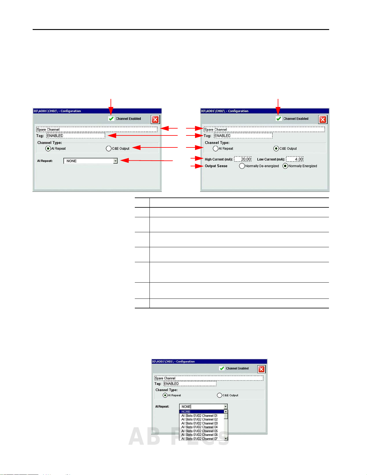
Configure I/O Chapter 6
2
1
1
3
4
5
6
7
Configure Analog Output Characteristics
After the output is created by entering a description, and tag name you can
configure the analog output characteristics.
Figure 39 - Analog Output Configuration Faceplate
Item Description
1 Channel Enabled - This feature controls the channel parameters configuration.
2 Description (maximum length 40 characters) - The description is shown in the Module Type Faceplate to
describe the channel. Be descriptive for quick navigation and selection.
3 Tag Name (maximum length 20 characters) - The tag name i s used in the Module Type faceplate to identify
the channel. Use field device names for Cause and Effect selection/presentation.
4 Channel Type - The Analog Output channel can be set to either an AI Repeat or C&E Output. Required
subparameters vary according to the option you choose here.
5 AI Repeat - A pull-down menu of the analog input channels. The selected analog input channel value is
repeated out of the OptiSIS solution, typically to pass to another system or to display on a bar graph style
display.
6 High/Low Current (mA) - Current value sent to the analog output when the Cause and Effect chart action
requires the output to be energized (high - 20 mA, max) or de-energized (low - 0 mA, min).
7 Output Sense - Normal state of the output device.
To configure an analog output, follow these steps.
1. Select and configure the Channel Type.
• AI Repeat allows you select which channel this output is able to
repeat on the output.
AB PLCs
Rockwell Automation Publication 1711-UM004B-EN-P - September 2016 61
Page 62

Chapter 6 Config ure I/O
• C&E Output makes the analog output available to the Cause and
Effect charts. Configure Low/High Current (0…20 mA) and Output
Sense as required.
2. Click to close the configuration faceplate.
3. To make your changes to the controller, you can download configuration
by using the turnkey at the front of the panel.
IMPORTANT On the I/O configuration display, the I/O channels that you configured or
changed appear as yellow. The yellow box indicates that there are
differences between what you configured and what the controller is
running.
62 Rockwell Automation Publication 1711-UM004B-EN-P - September 2016
Page 63

Configure I/O Chapter 6
4
5
2
3
1
Configure Digital Output Characteristics
After the output is created by entering a description and tag name, you can
configure the digital output characteristics.
Figure 40 - Digital Output Configuration Faceplate
Item Description
1 Channel Enabled - This feature controls the channel parameters configuration.
2 Description (maximum length 40 characters) - The description is shown in the Module Type faceplate
3 Tag Name (maximum length 20 characters) - The tag name is used in the Module Type Faceplate to
4 Output Sense (normally de-energized or normally energized) - Normal state of the output device.
5 Unlatch Output - With this box cleared, the digital output latches. To unlatch, the logic demand first
to describe the channel. Be descriptive for quick navigation and selection.
identify the channel. Use field device names for Cause and Effect selection/presentation.
must return to Off and then be reset (either by the HMI, by the external Modbus Reset being toggled
to 1, or - if applicable - by driving TRUE any configured Reset (R) inputs in the appropriate Cause and
Effect column). With this box cleared, the digital output resets automatically once the logic demand
is Off.
To configure the digital output, follow these steps.
1. Select the type of output sense required.
2. Configure the Unlatched Output setting as required.
3. Click to close the configuration faceplate.
AB PLCs
Rockwell Automation Publication 1711-UM004B-EN-P - September 2016 63
Page 64

Chapter 6 Config ure I/O
4. To make your changes to the controller, you can download configuration
by using the turnkey at the front of the panel.
IMPORTANT On the I/O configuration display, the I/O channels that you configured or
changed appear as yellow. The yellow box indicates that there are
differences between what you configured and what the controller is
running.
Validate Configuration
Once your system has been fully configured, check the design against your
requirements specification.
64 Rockwell Automation Publication 1711-UM004B-EN-P - September 2016
Page 65

Chapter 7
Configure Logic
The OptiSIS solution offers the ability to configure Cause and Effect logic that
is based on a set of signals previously configured. Multiple Cause and Effect
charts are available for configuration:
• 10 charts for the 50 I/O solution
• 20 charts for the 100 I/O solution
The Cause and Effect charts are configured by using two signal categories inputs and outputs.
Inputs include the following:
• Physical input alarms (for example, AI HH, digital alarm)
• Internal parameters (for complex logic creation)
• Modbus inputs (for writing from external packages)
Outputs include the following:
• Physical outputs (for example, DO and AO)
• Internal parameters (for complex logic creation)
Internal parameters are available on preallocated, read-only Modbus addresses.
Modbus inputs are available on preallocated writable Modbus addresses, and
can be used on the Cause and Effect charts.
ATT EN TI ON : When writing to a Modbus input, any effect on a safety-related
function must follow the requirements on IEC61511.
A logic expression is applied to the Causes (inputs) to generate the
Effect (outputs).
ATTENTION: The OptiSIS solution is a critical part of your safety system and
changes must follow formal Management of Change (MOC) process. Security
measures have been taken to avoid unauthorized changes to the SIS
configuration. The MOC process includes, but is not limited to, an impact
analysis of the change, documented implementation and test procedures,
and identification of any additional measures that are required while the
change is made. An MOC example is not provided in this document.
AB PLCs
Rockwell Automation Publication 1711-UM004B-EN-P - September 2016 65
Page 66

Chapter 7 Configure Logic
3
5
2
1
4
2
Using Cause and Effect Charts
This section describes the Cause and Effect Chart display and the steps to
configure the logic.
Figure 41 - Cause and Effect Chart Configuration
Item Description
1 Cause and Effect Description (two lines)
2 Logical elements (for example, OR, AND, VOTED, and ENABLE)
3 Input tag name
4 Time delay (only used with TOn and TOff)
5 Output tag name
Cause and Effect charts allow the system to act on inputs to control outputs.
To configure the chart, follow these steps.
1. Select the input that you want to monitor and select the details of the
monitoring that takes place, such as alarm level.
2. Select the output that you want to control.
3. Select the type of logic that is used to control the desired output.
The OptiSIS solution is built with nine different logic functions for
controlling outputs.
66 Rockwell Automation Publication 1711-UM004B-EN-P - September 2016
Page 67

Table 5 - Logic Functions
Logic Function Description
ENABLE For ENABLE functions, when the input condition is TRUE, then the remaining logic
functions in the Cause and Effect column (OR, NOT OR, AND, NOT AND, TOn, TOff, and
2(ooN)) are enabled.
If the ENABLE is present and not TRUE, then all other logic functions that are
configured in the corresponding column do not affect the output state.
IMPORTANT: When multiple ENABLE functions are present in a Cause and Effect
column, only one TRUE ENABLE function is required to enable the remaining logic
functions.
RESET For outputs configured as non-latching, once all other logic functions in the same
Cause and Effect column are in the normal state, the output returns to its normal
state when the Cause and Effect RESET function is TRUE.
For outputs configured as latching, once all other logic functions in the same Cause
and Effect column are in the normal state, the output returns to its normal state
when one of the following conditions is present:
• The Cause and Effect RESET function is TRUE
• A RESET command is issued from the HMI Alarm display
• The associated Modus bit is driven to TRUE
AND For AND logic functions, all inputs must be TRUE, and for NOT AND logic functions all
inputs must be FALSE, to trip the output.
If an ENABLE is present in the same column, the ENABLE must also be TRUE.
NOT AND
Configure Logic Chapter 7
OR For OR logic functions, any input made TRUE, and for NOT OR logic functions any
NOT OR
Timer (ON DELAY) When the input is TRUE for longer than the configured time (in the corresponding
Timer (OFF
DELAY)
2ooN Voting For 2(ooN) voting functions, at least two input conditions must be TRUE to trip the
input made FALSE, trips the corresponding output.
If an ENABLE is present in the same column, the ENABLE must also be TRUE.
row), then the corresponding output is tripped.
If an ENABLE is present in the same column, the ENABLE must also be TRUE.
When the input is TRUE, the output trips immediately. Once the input returns to
FALSE, the output is driven to the normal state after the configured time (in the
corresponding row) has elapsed.
A latched output can only be reset after the associated off-delay timers have expired.
If an ENABLE is present in the same column, the ENABLE must also be TRUE to trip
the output.
corresponding output.
If ENABLE is present in the same column, then the ENABLE must also be TRUE.
AB PLCs
Rockwell Automation Publication 1711-UM004B-EN-P - September 2016 67
Page 68

Chapter 7 Configure Logic
Configuration Methods
There are three methods you can use to configure the Cause and Effect charts:
•The HMI display
• Back up and restore
• The Offline Configuration Tool (see Appendix A
and Effect Charts on page 108)
- Configure Cause
Configure Cause and Effect Charts by Using the HMI Display
Follow these steps to use the HMI display to configure the different types of
logic that can be used with OptiSIS solution.
1. To go to the Operator display, press .
2. Log in as Engineer.
See Application Accounts on page 42
3. Press Configuration .
4. From the Operator display, press .
.
The first Cause and Effect chart opens. You can scroll through the Cause
and Effect charts when you press either or .
5. Press an input field.
The I/O Select - Inputs faceplate appears.
6. Select the Input and the Alarm Level.
7. Press Select Input.
The I/O Select - Inputs faceplate disappears.
68 Rockwell Automation Publication 1711-UM004B-EN-P - September 2016
Page 69

8. Press an output field.
Logic
Funct ions
(Available)
Logic
Functio ns
(Selected)
The I/O Select - Outputs faceplate appears.
9. Select the required output.
10. Press Select Output.
The I/O Select - Outputs faceplate disappears.
Configure Logic Chapter 7
11. Select the logic function that you want to use from the tools table.
12. To place the logic expression, press in the intersecting box for the input
and output.
IMPORTANT An input and output must be selected before you can add the logic function.
13. To configure the rest of the chart, repeat steps 5
…12.
14. To configure the remaining Cause and Effect charts, repeat steps 1
…12.
AB PLCs
Rockwell Automation Publication 1711-UM004B-EN-P - September 2016 69
Page 70

Chapter 7 Configure Logic
15. Turn the logic write keyswitch.
The keyswitch is on the front of the door, below and to the left of the
HMI. The download display appears.
IMPORTANT The Verify After Download setting enables a verification process that
compares the downloaded values with the configured values.
16. Press Download.
The download process begins. The process status can be monitor
download display.
ATTENTION: The download process can take up to 2 minutes. The system
suspends operation during the download process.
17. When the download is complete, press to close the faceplate.
70 Rockwell Automation Publication 1711-UM004B-EN-P - September 2016
Page 71

Configure Logic Chapter 7
Hinged Door Covering
the USB Ports
6181X Bottom View 6181P Front View6181P Bottom View USB Ports
Back up and Restore
The OptiSIS solution configuration can be backed up or restored from a USB
drive. This function allows the operating system to be backed up for record and
management of change (MOC) purposes. This function also aids in disaster
recovery or when you revert to a previous version.
IMPORTANT The Save to USB feature copies the configuration from the controller to the
USB drive. The Load from USB feature loads the configuration from the USB
drive to the controller.
The following best practices apply to all removable devices such as USB drives,
external hard disks, and SD cards.
• Do not mix personal and business usage.
• Do not use personal USB drives in customer computers.
• Do not plug USB drives that contain customer information into your
personal computer.
• Format the device before the first use.
• Virus scan USB drives.
Install the USB Drive
ATTENTION: The bottom side USB ports on the 6181X HMI are functionally
hot-pluggable in an environment that is known to be nonhazardous. For
European Zone 2 applications, do not use the USB ports unless the area is
known to be nonhazardous.
Back up the Configuration
To upload the configuration files, follow these steps.
1. Log in as Engineer.
See Application Accounts on page 42
2. To go to the Maintenance display, press .
AB PLCs
Rockwell Automation Publication 1711-UM004B-EN-P - September 2016 71
.
Page 72

Chapter 7 Configure Logic
Download from USB Drive
to Controller.
Upload from Controller to
USB Drive.
Refresh
3. From the Maintenance display, press until the Configuration
Load/Save display appears.
4. Specify a file name in the Save Filename field.
5. Press Upload from Controller to USB.
Figure 42 - Storing Current Configuration to Your USB Drive
IMPORTANT The upload process can take up to 2 minutes.
IMPORTANT The solution automatically creates a separate folder in the root folder of your
USB drive to store the configuration as shown in Figure 42
(E:\OptiSIS50\ or
E:\OptiSIS100\).
72 Rockwell Automation Publication 1711-UM004B-EN-P - September 2016
Page 73

Configure Logic Chapter 7
Load or Restore a Configuration
To download a configuration file to the controller, follow these steps.
1. Log in as Engineer.
See Application Accounts on page 42
2. To go to the Maintenance display, press .
3. From the Maintenance display, press until the Configuration
Load/Save display appears.
4. Connect the USB drive.
5. Verify that the configuration file is listed in the USB Device field. If the
file is not listed, press the Refresh button.
6. Select the configuration file. If multiple files are stored in the USB drive,
confirm that the correct file is highlighted.
7. If verification is required, check the Verify After Load checkbox.
8. Turn the Logic Write keyswitch to enable the Load from USB to
Controller button.
9. Press Download from USB to Controller button.
10. Once the download is complete, remove the USB device and close the
enclosure door if the door was open during the procedure.
IMPORTANT The solution requires the configuration file to be stored in a separate folder
in the root folder of your USB drive (E:\OptiSIS50\ or E:\OptiSIS100\). If the
folder does not exist, you must create it.
.
IMPORTANT The Verify After Download setting enables a verification process that
compares the downloaded values with the values in the configuration file.
AB PLCs
Rockwell Automation Publication 1711-UM004B-EN-P - September 2016 73
Page 74

Chapter 7 Configure Logic
Notes:
74 Rockwell Automation Publication 1711-UM004B-EN-P - September 2016
Page 75

Communication
Chapter 8
Introduction
IP Addresses
Using Modbus Communication
The OptiSIS solution provides Ethernet and serial communication to external
devices using Modbus RTU or Modbus TCP/IP. Additionally, it supports the
integration of field devices via HART protocol. This chapter covers the details
of these communication protocols.
Table 6 - IP Addresses
IP Address Description
192.168.0.1 Modbus TCP/IP and HART passthrough
192.168.2.1 HMI communication
192.168.1.1 Modbus TCP/IP
192.168.4.1 HMI communication
192.168.3.1 Not connected
192.168.5.1 Not connected
The OptiSIS solution has two serial ports and two Ethernet ports for external
communication using Modbus RTU and Modbus TCP/IP, respectively. All
configuration registers are read-only. Only a limited number of variables are
read/write. See Appendix E
addressable parameters and use.
on page 123 for Modbus RTU settings and
AB PLCs
Rockwell Automation Publication 1711-UM004B-EN-P - September 2016 75
Page 76

Chapter 8 Communication
HART Protocol
The OptiSIS solution supports HART protocol, which lets you integrate Field
Device data into your safety application. Typical uses of this data include the
following:
• To display, compare, and alarm (externally) the measured process
variable from the analog input channel with the process variable value
that is transmitted over HART from the field device to detect
discrepancies.
• To monitor the field device status, report device status, and report
diagnostic errors or manual configuration changes.
Based on your specific needs, you can configure your solution in one of two
ways:
• HART Data over Modbus uses the HART command #03 to collect data
automatically from any smart field device that is connected to either an
input channel or analog output channel. The data is made available to
read through Modbus (RTU or TCP) interface for display or for
consumption by an outside system.
• HART Device management through an AMS (Asset Management
System) lets you manage smart field devices by creating an Ethernet
connection from your solution to your AMS.
HART Data Over Modbus Network
HART Data over Modbus is implemented by connecting input channels in
your OptiSIS solution to smart transmitters or an analog output to a smart
positioner. The devices are polled automatically using HART command #03 to
collect data from the field device and made available to read by using Modbus if
necessary (see Appendix E
The data available from channels that are connected to HART enabled field
devices provides the following information:
• Current in milliamps
• Process measurement in engineering units
• 2nd, 3rd, and 4th variables where applicable to the field device
• Status of the field device
• Time in milliseconds since the last update
ATTENTION: HART command #03 provides different data depending on the
specific device, which must be used in accordance with the published
recommendations of the device manufacturer.
).
76 Rockwell Automation Publication 1711-UM004B-EN-P - September 2016
Page 77

Communication Chapter 8
HART Device Management by Using an AMS
The OptiSIS solution is enabled to allow an FDT (version 1.0) compatible
AMS to communicate with smart field devices. The AMS is enabled only on
the first of the two customer ports.
The AMS requires that the AADvance CommDTM is installed, to allow any
DeviceDTM to interface HART data between the AMS and the Field Device.
The AADvance CommDTM can be downloaded from the Product
Compatibility and Download Center (PCDC)
http://www.rockwellautomation.com/global/support/pcdc.page?
The installation and use information is available from Rockwell Automation
Literature Library http://www.rockwellautomation.com/literature/
ATTENTION: When using HART Passthru, a field device can respond to
commands from the AMS. This response can, in turn, disable a safety
function or initiate a demand.
.
.
AB PLCs
Rockwell Automation Publication 1711-UM004B-EN-P - September 2016 77
Page 78

Chapter 8 Communication
Notes:
78 Rockwell Automation Publication 1711-UM004B-EN-P - September 2016
Page 79

Operation
Chapter 9
Monitor System State
The OptiSIS solution provides diagnostics that allow you to monitor the
system state.
On the Maintenance displays, you can view overall system status, configure
inputs and outputs, change passwords, and handle configuration files, if
necessary. Navigation to any of these aspects is accomplished by using the
navigation arrows at the bottom of the display.
System Status
The system status display gives you a quick glance at information about overall
system health. Based on the color of the modules in the system diagram, you
can determine the overall status:
• Gray = healthy module
•Yellow = warning
•Red = faulted module
IMPORTANT When the Program Enable Key is inserted, the processors are shown in
yellow. See Figure 43 on page 80
.
To get a more detailed overview of the system, press the module that you are
interested in to get that information. You can view steady-state operation,
confirm that the wiring is correct, and troubleshoot inputs and outputs.
AB PLCs
Rockwell Automation Publication 1711-UM004B-EN-P - September 2016 79
Page 80

Chapter 9 Operation
Processor Group
Flexible I nput
Group
Digital Output
Group
Analog Output Group
Digital Output Group
Flexible Input
Group
1
2
4
3
Figure 43 - System Status Display
Item Description Item Description
1 Input Filter Time (ms) - Time that the inputs must remain in the alarm state
before the alarm can be generated (0…500 ms)
Any Force Present - A force is active on an input or output device. PLC - HMI Status LAN A (CPU A) - Status of the Ethernet communication
CPU Power Fault - At least one processor power feed is outside of the
specified range (18…32V DC). PLC - HMI Status LAN B (CPU B) - Status of the Ethernet communication
Any Input Power Feed Failed - Notification of complete Feed A/B failure.
DO Group 1 V Fault - Voltage from either field power supply for DO Group 1
is less than the minimum value (18V DC).
DO Group 2 V Fault - Voltage from either field power supply for DO Group 2
is less than the minimum value (18V DC).
CPU Temperature - The temperature of any processor module is greater
than the maximum value (80 °C [176 °F]).
MTTR Exceeded - For a High Availability configuration, a system fault has
exceeded the configured mean time to restoration.
2 Common Facilities, continued
Duplicate Output Detected - An output has been used in two different
columns of the Cause and Effect char ts.2 Common Facilities
link between the industrial computer and processor A.
link between the industrial computer and processor B.
Relay Discrepancies - A discrepancy exists between the commanded
output and the status of the output device. An indication is available for
each DO Group present in the system.
3 Rolling Counter - Visual indication of successful communication.
4 Suppress/Force, Permissive - Enable Permissive to suppress/force alarms/tags.
Suppress/Force, Remove All - Reactivate all signals that are currently
suppressed and remove all forces.
80 Rockwell Automation Publication 1711-UM004B-EN-P - September 2016
Page 81

Operation Chapter 9
Processor Module Status
When in Operation mode, you can press the Processor group, to view the
processor status. This view gives you information to identify issues with any of
the system processor modules. This information includes the following:
•Health
• Ready/online state
• Battery status
•Processor power feeds status
•Temperature
• Program enable key
• Locked and unlocked variables
• Real-time clock (UTC)
There are separate columns for each processor in the system to give you
individualized status monitoring.
Figure 44 - Processor Module Status
AB PLCs
Rockwell Automation Publication 1711-UM004B-EN-P - September 2016 81
Page 82

Chapter 9 Operation
Flexible Input Module Status
When you press a flexible input group, you can view the input module status.
The Flexible Input module groups, and the dedicated Analog Input and Digital
Input groups available in the 100 I/O solution, share similar displays. This view
gives you information to identify issues with any of the system input modules.
This information includes the following:
• Number of modules expected
•Number of modules online
• Slot location of the first module in the group
• Overall group health
• Online, Healthy, Ready, Run, and Shutdown status of each module
• Position of each module
• Current state, process variable value, and tag name for each channel
There is a legend that is provided in the lower left corner to explain the
meaning of each of the abbreviations for channel status.
IMPORTANT All channels are displayed to help with setup whether the channel is enabled
or not enabled.
Figure 45 - Flexible Input Module Status
82 Rockwell Automation Publication 1711-UM004B-EN-P - September 2016
Page 83
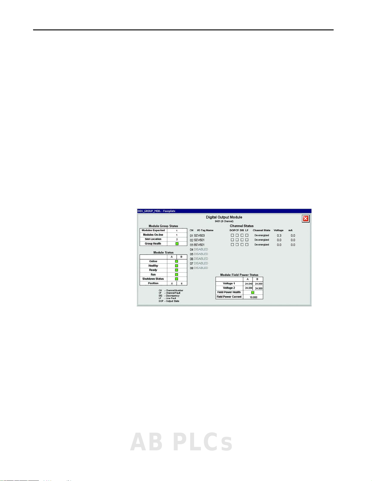
Operation Chapter 9
Digital Output Module Status
When you press the digital output group, you can view the digital output
module status. This view gives you information to identify issues with any of
the system digital output modules. This information includes the following:
• Number of modules expected
•Number of modules online
• Slot location of the first module in the group
• Overall group health
• Overall field power status and current value
• Field voltage of each module
• Online, Healthy, Ready, Run, and Shutdown status of each module
• Position of each module
• Current state, voltage and current values, and tag name for each channel
There is a legend that is provided in the lower left corner to explain the
meaning of each of the abbreviations for channel status.
Figure 46 - Digital Output Module Status
AB PLCs
Rockwell Automation Publication 1711-UM004B-EN-P - September 2016 83
Page 84

Chapter 9 Operation
Analog Output Module Status
When you press an Analog Output group, you can view the analog output
module status. This view gives you information to identify issues with any of
the system analog output modules. This information includes the following:
• Number of modules expected
•Number of modules online
• Slot location of the first module in the group
• Overall group health
• Online, Healthy, Ready, Run, and Shutdown status of each module
• Position of each module
• Current state, output (%), voltage and current values, and tag name for
each channel
There is a legend that is provided in to explain the meaning of each of the
abbreviations for channel status.
Figure 47 - Analog Output Module Status
84 Rockwell Automation Publication 1711-UM004B-EN-P - September 2016
Page 85

Operation Chapter 9
I/O Status
To view I/O status, follow these steps.
1. To go to the Maintenance display, press .
2. From the Maintenance display, press until the I/O Configuration
display appears.
3. Press or to highlight the appropriate input or output.
4. To view the status, press .
Flexible Input Group
To access the flexible input status, follow steps 1…4 to view Flexible Inputs
Slots (1 & 2 or 3 & 4) status. For an explanation of column colors, see Ta b l e 7
Table 7 - Column Colors
Color Description
Gray Normal (no fault, alarm, or force/suppress present)
Yellow Fault indication
Red Alarm indication - Text inside the rectangle indicates the active alarm: HIHI, LOLO, HI, or LO.
Blue Forced o r Suppresse d - Text inside rectangle indicates Forced (FRC) or Suppressed (SUP).
(1) If multiple alarms are active, only one is indicated (in the order of priority listed).
AB PLCs
.
(1)
Rockwell Automation Publication 1711-UM004B-EN-P - September 2016 85
Page 86

Chapter 9 Operation
3
1
6
2
7
4
11
10
5
9
8
You can view the device configuration faceplate when you press anywhere on
the channel row.
Figure 48 - Analog Input Configuration Faceplate
Item Description
1 Channel Type - The Flexible Input channel can be wired to either an Analog Input or Digital Input
(Figure 49 ). Required subparameters vary according to the option that you choose here.
2 Enable Force (maintenance action) - When checked, the value that is specified in the Force Value field is
written to the analog input, which overrides the physical input value. The Enable Force setting can only
be checked/unchecked when the Force Permissive is TRUE.
3 Current PV - The current Process Variable value (EU).
4 Maximum/Minimum PV - Input Process Variable maximum and minimum settings, as corresponding to
20 mA and 4 mA respectively.
5 Force Value (maintenance action) - When Enable Force is checked, this value overrides the physical input
value. The Force Value must be within the minimum and maximum PV values.
6 Units (maximum length 6 characters) - Engineering units relevant to the input that is configured (for
example, barg, degC, degF, %LEL, ppm).
7 Suppress Alarms and Trip (maintenance action) - When checked, the configured alarms and trips are not
generated. This is typically used for testing or replacing field devices. The Suppress Alarms and Trips
setting can only be checked/unchecked when the Suppress Permissive is TRUE.
8 Alarm Unlatched - With this box cleared, any configured input alarm latches when the alarm occurs. To
unlatch, the input first has to return to a normal value and then be reset (either by the HMI or by the
external Modbus Reset being toggled to 1).
With this box checked, the analog input or digital input alarm resets once the input is at a normal value.
9 Alarm on Fault - With this box cleared, a field or module fault does not cause the input to generate any
trip alarms (although faults are still reported).
With this box checked, a field or module fault generates all trip alarms for the inputs affected.
10 Sts - Status of the associated condition, which is based on the physical input value or the forced value.
This status is non-latching, and the Suppress Alarms and Trips function do not affect it.
• Gray = Condition not active
• Red = Condition active
11 Alm - Status of the alarm, which is used by the Cause and Effect charts logic. The Alarm Unlatched
configuration setting affects the status.
• Gray = Alarm not active
• Red = Alarm active
86 Rockwell Automation Publication 1711-UM004B-EN-P - September 2016
Page 87

Operation Chapter 9
2
1
5
3
6
4
Figure 49 - Digital Input Configuration Faceplate
Item Description
1 Channel Type - The Flexible Input channel can be wired to either an Analog Input (Figure 48) or Digital
Input. Required subparameters vary according to the option that you choose here.
2 Switching level (mA) - The level across which the input is deemed to be energized (above this value) or
de-energized (below this value). Typically the default value (1.75 mA) is sufficient.
3 Input Sense (Normally Open or Normally Closed) - No rmal state of the field switch.
4 Line Monitoring Fitted - Check this box for line monitored switches/devices with End-of-Line (EOL)
resistors installed. Clear this box for non-line monitored devices.
With this box cleared, open circuit and short circuit faults are not generated.
With this box checked, open circuit and short circuit faults are generated.
5 Alarm Unlatched - With this box cleared, any configured digital input alarm latches when the alarm
occurs. To unlatch, the input first has to return to a normal value and then be reset (either by the HMI or
by the external Modbus Reset being toggled to 1).
With this box checked, the digital input alarm resets once the input is at a normal value.
6 Alarm on Fault - With this box cleared, a field or module fault does not cause the input to generate any
trip alarms (although faults are still reported).
With this box checked, a field or module fault generates the configured trip alarm for the digital input.
AB PLCs
Rockwell Automation Publication 1711-UM004B-EN-P - September 2016 87
Page 88

Chapter 9 Operation
3
1
2
4
5
6
7
Digital Output Group
To access the digital output status, follow steps 1…4 (page 85) to view Digital
Output Slots (5 and 6 or 7 and 8) status.
You can view the device configuration faceplate when you press anywhere on
the channel row.
Figure 50 - Digital Output Configuration Faceplate
Item Description
1 Enable Force (maintenance action) - When checked, the digital output state can be toggled using the Force Toggle to 1 checkbox, which
overrides the logic demand. The Enable Force setting can only be checked/unchecked when the Force Permissive is TRUE.
2 Current State - Current state of the physical digital output (either 'On' [energized] or 'Off' [de-energized]). The current state can differ from
the Logic Demand when Force Enable is TRUE.
3 Logic Demand - Status of the demand for the output from the Cause and Effect charts (either 'On' [tripped] or 'Off' [normal - no demand]).
4 Force Toggle to 1 (maintenance action) - When Enable Force is checked, this checkbox allows the output to be toggled on (Energized) and off
(De-energized), which overrides the logic demand from the Cause and Effect charts. This option can be used, for example, during loop
testing.
5 Suppress Alarm and Output (maintenance action) - When checked, the logic demand is overridden, and the physical output is driven to the
normal operating state configured in the Output Sense setting. This is typically used for maintenance of field devices. The Suppress Alarm
and Output setting can only be checked/unchecked when the Suppress Permissive is TRUE.
6 Output Sense (Normally De-energized or Normally Energized) - Normal state of the output device.
7 Unlatch Output - With this box cleared, the digital output latches. To unlatch, the logic demand first must return to 'Off' and then be reset
(either by the HMI, by the ex ternal Modbus Reset being toggled to 1, or - if applicable - by driving TRUE any configured Reset (R) inputs in
the appropriate Cause and Effect column). With this box checked, the digital output resets automatically once the logic demand is 'Off'.
88 Rockwell Automation Publication 1711-UM004B-EN-P - September 2016
Page 89

Operation Chapter 9
1
2
3
4
Analog Output Group
To access the analog output status, follow steps 1…4 (page 85) to view Analog
Output Slots 9 and 10 status.
You can view the device configuration faceplate when you press anywhere on
the channel row.
Figure 51 - Analog Output Configuration Faceplate
Item Description
1 Channel Type - The Analog Output channel can be set to either an AI Repeat or C&E Output. Required
subparameters vary according to the option you choose here.
2 AI Repeat - A pull-down menu of the analog input channels. The selected analog input channel value is
repeated out of the OptiSIS solution, typically to pass to another system or to display on a bar graph style
display.
3 High/Low Current (mA) - Current value sent to the analog output when the Cause and Effect chart action
requires the output to be energized (high - 20 mA, max) or de-energized (low - 0 mA, min).
4 Output Sense (normally de-energized or normally energized) - Normal state of the output device.
AB PLCs
Rockwell Automation Publication 1711-UM004B-EN-P - September 2016 89
Page 90

Chapter 9 Operation
1
1
Internal Parameters
Follow steps 1…4 (page 85) to view Internal Parameter status.
Item Description
1 Sts (Status) - Gray = False; Red = True
Modbus Input Status
Follow steps 1…4 (page 85) to view Modbus Input status.
Item Description
1 Sts (Status) - Gray = False; Red = True
90 Rockwell Automation Publication 1711-UM004B-EN-P - September 2016
Page 91

Operation Chapter 9
HMI Alarm Icon
View Alarms
The Alarm display subscribes to and displays all alarms from the system. From
this display, you can view a list of the active alarms, monitor alarm details,
acknowledge one or multiple alarms and reset latched alarms.
Figure 52 - Alarm Status
1. To access the Alarm display, press the HMI Alarm icon on the main icon
toolbar.
Figure 53 - HMI Alarm Icon
When an alarm is active and unacknowledged, the background color of
the alarm flashes.
The HMI Alarm icon (Ta b l e 8
blinks if you must acknowledge an alarm.
Table 8 - Alarm Icon
Alarm Icon Alarm Priority Alarm Icon Alarm Priority
Urgent Low
High No alarm active
Medium
) changes based on alarm priority and
AB PLCs
Rockwell Automation Publication 1711-UM004B-EN-P - September 2016 91
Page 92

Chapter 9 Operation
The appearance of the alarms in the Alarm display is based on the alarm
priority (Ta b l e 9
). Active and unacknowledged alarms blink until an
acknowledge command is issued or the alarm returns to normal.
Table 9 - Alar m Prior ity
Alarm Priority Description Text Color
All priority levels Alarm has returned to normal (unacknowledged)
Low Line faults
Medium System level alarms
High High and Low alarms
Urgent MTTR Exceeded, High High, Low Low, Digital
Output Change of State, Digital Input Alarm
The alarm state represents the status of the alarm, as shown in Ta b l e 1 0 .
Table 10 - Alarm State
Alarm Color Alarm Definition
In Alarm, Unacknowledged
In Alarm, Acknowledged
Normal, Unacknowledged
92 Rockwell Automation Publication 1711-UM004B-EN-P - September 2016
Page 93

Operation Chapter 9
12
345 6
Details Pane
2. Use the Alarm display commands (Figure 54) to acknowledge, refresh,
or reset alarms.
• To acknowledge the alarm, select the specific alarm and press the
appropriate command button to stop the message from flashing.
• To reset the alarm, press .
Figure 54 - Alarm Display Commands
Item Description
1 Details Pane - Shows or hides the details pane at the bottom of the display.
2 Refresh - Refreshes your alarm display.
3 Ack - Acknowledge the selected alarm.
4 Ack Page- Acknowledge all alarms that are shown on the display.
5 Ack All - Acknowledge all alarms.
6 - Reset latched alarms and trips
AB PLCs
Rockwell Automation Publication 1711-UM004B-EN-P - September 2016 93
Page 94

Chapter 9 Operation
Table 11 - Alarm Types and Actions
Category Description Action
Common Facilities Any force present Alarm to HMI.
AADvance controller system fault
AADvance controller I/O fault
(for configured I/O)
AADvance controller fault (system healthy)
AADvance controller V1 / V2 faults
AADvance DO group 1 / 2 V faults
AADvance CPU temperature high
MTTR countdown/exce eded
Duplicate output detected
PLC - HMI LAN A connection
PLC - HMI LAN B connection
Power supply fault
Purge ala rm
Rolling count Display on System Status display.
AADvance controller fault
(controller/module/channel/field)
Logic AI trip (limit exceeded) Alarm to HMI.
DI trip (input in alarm state) Alarm to HMI.
DO state change (output in tripped state) Alarm to HMI.
Operator action Reset applied Status to HMI.
I/O suppress/force applied Status to HMI.
Display on System Status display.
Cause and Effect logic performs function.
Cause and Effect to highlight tag.
Cause and Effect logic performs function.
Cause and Effect to highlight tag.
Cause and Effect to highlight tag.
HMI to show suppression / force on I/O
display.
94 Rockwell Automation Publication 1711-UM004B-EN-P - September 2016
Page 95

Operation Chapter 9
View Warnings
The Warning display lists active system warnings, such as restricted access level
and active overrides/forces.
Table 12 - Warning Severity
Warning Level Description Color
0No Warning
1 Level 1: Preventing Operation
2 Level 2 Function Disabled/Bypassed
Figure 55 - Warning Status
Reset after Trip
If the logic, as configured, detects a trip condition (for example, pressure
transmitter high level exceeded), the OptiSIS solution performs the configured
actions, typically de-energizing valves, or fault contacts to other systems. No
operator interaction is required. After trip conditions have cleared, a reset is
required to return to a healthy state.
Reset by Using the HMI
Latched input alarms and tripped outputs can be reset from the HMI by using
the Reset button available in the Alarm display. If all input conditions have
returned to the healthy state, any latched trips unlatch and outputs revert to
their healthy state. Follow these steps to reset from the HMI.
1. To go to the Alarm display, press .
2. To reset input alarms and tripped outputs, press .
AB PLCs
Rockwell Automation Publication 1711-UM004B-EN-P - September 2016 95
Page 96

Chapter 9 Operation
Reset by Using Supplied Modbus Point
To reset the OptiSIS solution remotely, pulse Modbus Coil 1 (address 00001)
to 1. A pulse time of 1…2 seconds is typically sufficient.
Pulsing Modbus Coil 1 has the same effect as pressing Reset ( ) on the
OptiSIS Alarms display. If all input conditions have returned to healthy state,
any latched trips unlatch and outputs revert to their healthy state.
ATTENTION: Unlike the OptiSIS Alarms display reset, the Modbus reset can
be activated regardless of the HMI user who is logged on. It is recommended
that sufficient access controls are placed on this function to help prevent
unauthorized interaction with the OptiSIS solution.
96 Rockwell Automation Publication 1711-UM004B-EN-P - September 2016
Page 97

Maintenance
Chapter 10
Introduction
Technical Support Options
The maintenance person must be experienced in working on electronic
equipment and in particular safety-related systems. They must have knowledge
and experience of local operating and safety standards. Failure to follow these
recommendations can result in situations that can lead to system damage and
even personal injury.
Technical Support is offered for your base OptiSIS solution and is available
8 a.m. to 5 p.m. in your local time, Monday through Friday.
The Technical Support specialist requires the following information from your
Welcome Kit (included in your OptiSIS solution package):
• Business partner (BP) ID number
•Direct dial code
• Equipment ID - found on the label on the enclosure
Use the following lines to note your OptiSIS solution information. This
information helps when contacting technical support.
BP ID: _____________________________________________________
Opening the Enclosure
Direct Dial Code: _____________________________________________________
Equipment ID: _____________________________________________________
ATTENTION: When working on or near energized electrical equipment,
follow established electrical safety-related work practices. See NFPA 70E
Standard for Electrical Safety in the Workplace.
AB PLCs
Rockwell Automation Publication 1711-UM004B-EN-P - September 2016 97
Page 98

Chapter 10 Maintenance
Repair Procedures
Processor Module Battery Replacement
You can replace physical components. See the AADvance Maintenance and
Troubleshooting Manual, publication ICSTT-RM406
.
Electrostatic Precautions
The electronic components of these systems are susceptible to electrostatic
discharge (ESD). Be sure to take the following precautions:
• Always wear an anti-static wriststrap (or equivalent) when handling any
electrostatic sensitive components.
• Controller modules are especially sensitive to electrostatic discharge. Pay
special attention not to touch the module connectors or any exposed
printed circuit board components.
TIP Battery design life is based on operating at a constant temperature of 25 °C
(77 °F) and low humidity. High humidity/temperature and frequent power
cycles are all factors that shorten the batteries operational life.
The battery has a design life of 10 years when the processor module is
continually powered; for processor modules that are unpowered, the design life
is up to 6 months.
ATTENTION: The OptiSIS solution uses the processor module battery-backup
feature to retain the I/O configuration parameters and the cause and effect
logic configuration when power is lost.
ATTENTION: The battery can explode if mistreated. Do not attempt to
recharge, disassemble, or dispose of in a fire.
This product contains a sealed lithium battery (recommended type BR2032),
which can be replaced during the life of the product.
At the end of its life, collect the battery that is contained in this product
separately from any unsorted municipal waste.
The collection and recycling of batteries helps protect the environment and
contributes to the conservation of natural resources as valuable materials are
recovered.
ATTENTION: Batteries must only be changed in an area that is known to be
non-hazardous.
98 Rockwell Automation Publication 1711-UM004B-EN-P - September 2016
Page 99

Maintenance Chapter 10
Battery Cover Screw
Blue Ribbon
To replace a faulty battery, do the following:
1. To remove the battery cover, use a small Phillips screwdriver to loosen
the cover screw.
2. Remove the battery by pulling on the blue ribbon.
3. Insert a new battery with the positive (+) terminal to the right.
4. Trap the ribbon behind the new battery so it can be removed in the
future and then push the battery into the holder.
5. Replace the cover and secure it with the screw.
6. Push Fault Reset on the processor module.
The processor Healthy indicator turns green (applies if the module is
part of a running system).
The functions that the battery maintains on complete loss of power are:
• Real-time Clock - Used for Alarms and Events time stamp.
• Retained Variables - I/O and the Cause and Effect configuration
parameters.
• Diagnostics Logs - Backs up the internal processor diagnostic logs.
AB PLCs
Rockwell Automation Publication 1711-UM004B-EN-P - September 2016 99
Page 100
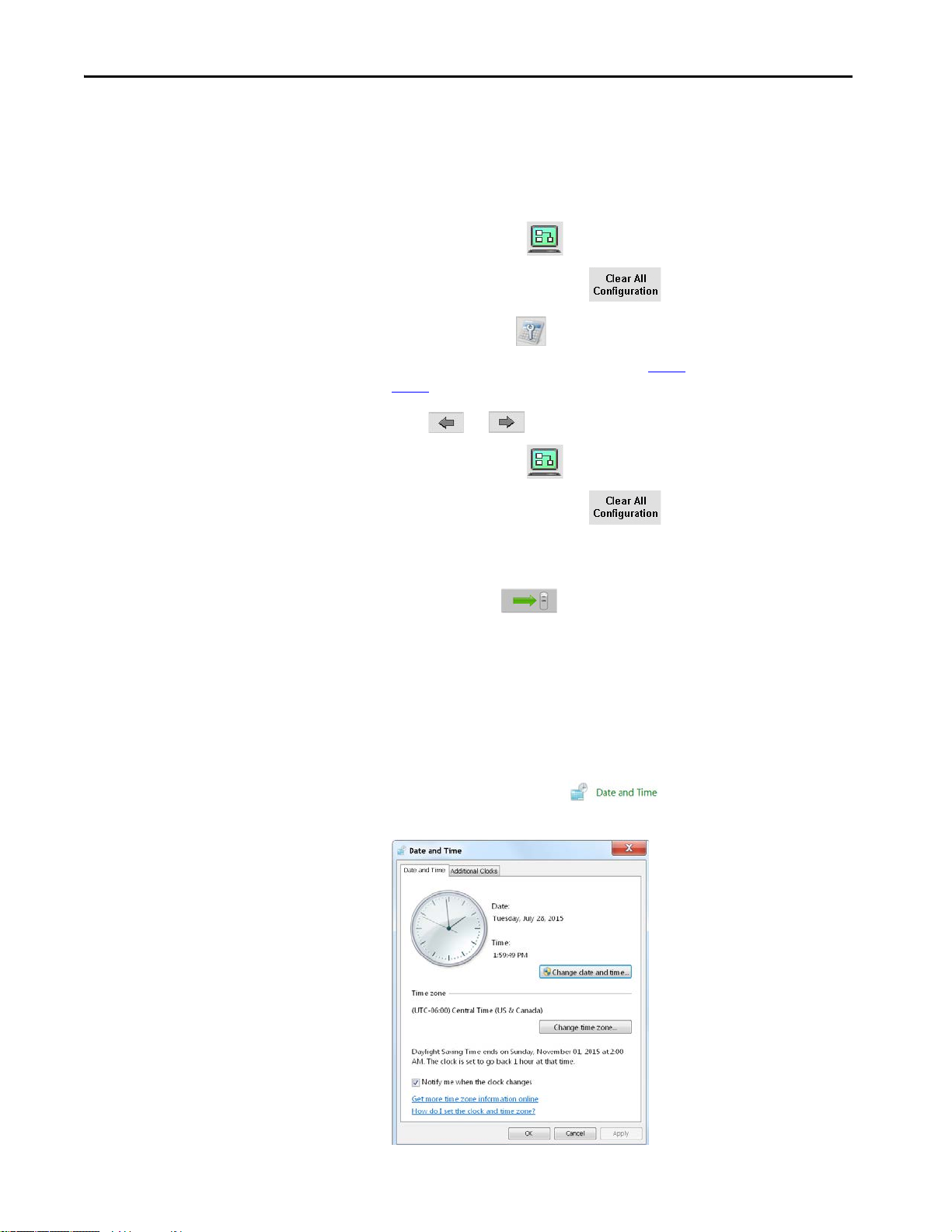
Chapter 10 Maintenance
Reset OptiSIS Solution Default Settings
To clear all configured Cause and Effect information and (if necessary)
configured I/O information, follow these steps.
1. On the Home display, log in as Engineer (in the FactoryTalk®
application).
2. Press Configuration .
3. Press Clear All Configuration .
4. Press Maintenance .
To clear the configured I/O, proceed to step 5
.
step 8
5. Press or until the I/O configuration display appears.
6. Press Configuration .
7. Press Clear All Configuration .
8. Turn the keyswitch to initiate a download.
. Otherwise, proceed to
Change Date and Time
9. On the Cause and Effect Configuration Download display,
press Download .
To modify the date and time that is displayed, follow these steps.
1. Log in as a Windows Administrator.
The default password is 1ADMINISTRATOR.
2. From the Start menu, choose Control Panel.
3. In the Control Panel, press .
The Date and Time window appears.
100 Rockwell Automation Publication 1711-UM004B-EN-P - September 2016
 Loading...