

Page 1

Installation Instructions
Bulletin 1694 Electronic circuit protection for 24V DC with IO-Link
WARNING: Electrostatically sensitive sub-assemblies can be destroyed by voltages far below the human perception threshold. These voltages already occur if you touch a component
or electrical terminals of a sub-assembly without being electrostatically discharged. The damage of a sub-assembly caused by an overvoltage is often not immediately
recognised, but will be noticed only after a longer operating time.
Mounting or actuation of the 1694 connector arm must only be effected at dead-voltage. For start-up the 1694 connector arm must be closed.
Device to be installed, operated and maintained by trained personnel only.
To secure device properly against unintended access, product shall be mounted in locked cabinet.
The device can’t be serviced or repaired.
Do not open device’s enclosure.
Table of contents
1. Bulletin 1694 Electronic circuit protection modules for 24V DC with IO-Link communication ................................................................... 2
1.1. 1694-PMD* and 1694-PMD2A10 Circuit Protection Module Technical data............................................................................... 3
2. Bulletin 1694. Power Feed 1694-PFD1244 with IO-link communication ................................................................................................... 8
2.1. 1694-PFD1244 Power Feed Module Technical data .................................................................................................................. 9
3. IO-Link technology review ....................................................................................................................................................................... 15
3.1. Accessing IO-Link Data............................................................................................................................................................. 16
4. IO-Link connector description used for 1694-PFD1244 .......................................................................................................................... 16
5. Signaling of operating status on 1694-PFD1244 Power Feed Module.................................................................................................... 17
6. Signaling of operating status on 1694-PMD* Protection Modules........................................................................................................... 18
7. Installation and configuration of 1694-PFD1244 and 1694-PMD* in Studio5000.................................................................................... 19
7.1. AOP Installation......................................................................................................................................................................... 19
7.2. Creating a Project...................................................................................................................................................................... 19
7.3. Adding a Controller.................................................................................................................................................................... 19
7.4. Adding a Point IO (Ethernet Adapter)........................................................................................................................................ 20
7.5. Adding an IO-Link Master.......................................................................................................................................................... 21
7.6. Registration of IODD file for Power Feed 1694-PFD1244......................................................................................................... 23
7.7. Connect the 1694-PFD1224 to the IO-Link Master ................................................................................................................... 25
7.8. Download the Project to Allen-Bradley Logix Controller............................................................................................................ 26
7.9. Exploring the 1694-PMD1244 Parameters in AOP ................................................................................................................... 28
7.9.1. Common Tab .................................................................................................................................................................. 30
7.9.2. Identification Tab ............................................................................................................................................................ 31
7.9.3. Observation Tab ............................................................................................................................................................. 32
7.9.4. Parameters Tab .............................................................................................................................................................. 34
7.9.5. Diagnosis Tab................................................................................................................................................................. 36
8. Device Parameters Details ...................................................................................................................................................................... 39
8.1. Cyclic Data ................................................................................................................................................................................ 39
8.2. Non-Cyclic Data ........................................................................................................................................................................ 43
9. Rockwell Automation Support ................................................................................................................................................................. 47
Page 2
Installation Instructions: Bulletin 1694 Electronic circuit protection for 24V DC with IO-Link
2
1. Bulletin 1694 Electronic circuit protection modules for 24V DC with IO-Link communication
Bulletin 1694 Electronic Circuit Protection is a modular solution with a max. system capacity of 40A. The protection modules come in fix and adjustable current
rating in a range from 1A…10A. Designed for 24V DC circuits, the 1694 provides comprehensive protection against short circuit and overcurrent conditions
while allowing for inrush current. 1694-PMD* and 1694-PFD1244 Provides IO-Link communication capability.
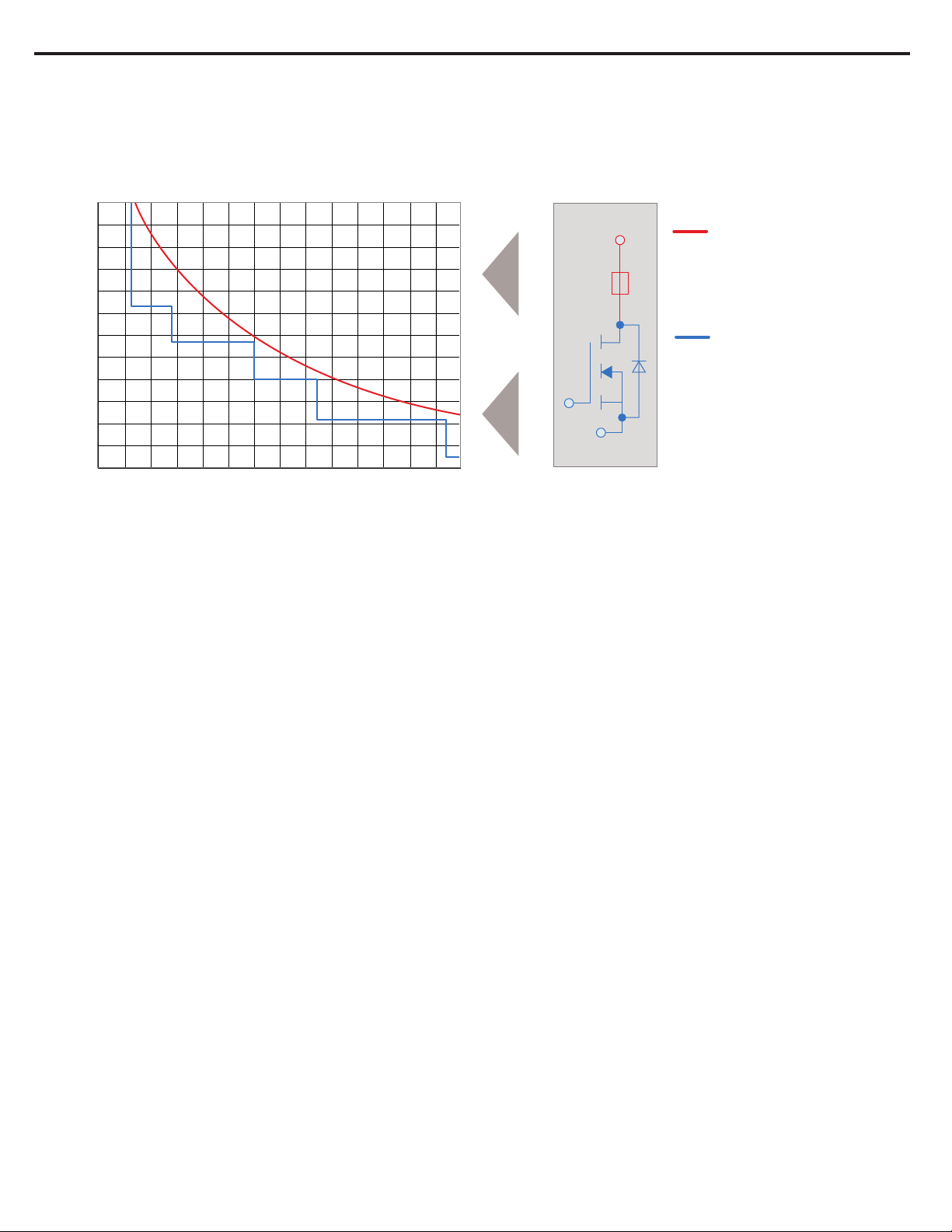
Basic trip curve and schematic diagram 1694-PMD
Schematic diagram
1.000
4 A
LINE
blade fuse
100
10
1
semiconductor
0,1
0,01
trip time in seconds
0,001
0,8 1,0 1,2 1,4 1,6 1,8 2,0 2,2 2,4 2,6 2,8 3,0 3,2 3,4 I
KS
4 A
LOAD
times rated current trip curve
Features
• Combination of supply modules, circuit protection and power distribution
• IO-Link communication to Logix Controller via Power Feed 1694-PFD1244 module. Main features:
- Current and Voltage monitoring,
- Statistics,
- Remote control,
- Error massaging.
• Selective load protection by means of electronic trip curve
• No accessories required for connecting the modules
• Width per channel only 12.5 mm (1-channel) or 6.25mm (2-channel)
• Integral fail-safe element, adjusted to current rating
• Switching capacitive loads up to 20,000 μF (at IN > 6A)
• Manual ON/OFF/reset momentary switch
• Clear status indication by means of LED and auxiliary contact (1694-PF power feed module)
• Wire connection via push-in terminals
• 1694-PMD* available in Class 2 version in nominal currents: 1A, 2A, 3A, 4A
• Adjustable circuit protection module 1694-PMD2A10 with trip current range from 1A to 10A.
Notes
• Connection to a higher or not reliably disconnected voltage can cause hazardous conditions or damages
• Only the intended Bulletin 1694 circuit protectors must be used
• The technical data of the circuit protectors used must be observed
• The entire power distribution system must only be installed by qualified personnel
• Only after expert installation must the device be supplied with power
• After tripping of the circuit protector and before reset, the cause of the anomaly (short circuit or overload) must be remedied
• The national standards must be observed for installation and selection of feed and return cables.
• Circuit protection modules 1694-PMD* must be operated with 1694-PFD1244.
• Circuit protection modules 1694-PMD2A10 can be operated with 1694-PFD1244 or 1694-PF* (Line +). Module is recognized automatically.
• IO-Link communication is provided by Power Feed 1694-PFD1244 to Protection Modules. Protection Modules cannot communicate directly with Logix Controller
and IO-Link master.
• Standard Protection Modules should not be used in IO-link configuration (for 1694-PMD2A10 see note above).
Publication 1694-IN001D-EN-E - August 2020 DIR 10005708550 (Version 03)Publication 1694-IN001D-EN-E - August 2020 DIR 10005708550 (Version 03)
Page 3

Installation Instructions: Bulletin 1694 Electronic circuit protection for 24V DC with IO-Link
3
1.1. 1694-PMD* and 1694-PMD2A10 Circuit Protection Module
Technical data (Tamb = +23 °C, UB = DC 24 V)
Operating voltage
Closed current I
1694-PM1 (1-channel)
1694-PM2 (2-channel)
U
B
0
DC 24 V (min. 18 V, max. 30 V)
(no battery-buffered applications)
in ON condition:
typically 5 mA
typically 8 mA
Reverse polarity protection Yes, without load
Rated current IN
1694-PM1 (1-channel)
1694-PM2 (2-channel)
Visual status indication
current ratings:
1 A, 2 A, 3 A, 4 A, 6 A, 8 A, 10 A
1A/1A, 2A/2A, 3A/3A, 4A/4A, 6A/6A
Green: Load circuit connected
by means of LED:
flashing
orange Load current warning limit reached
green:
orange: Overload or short circuit until disconnection
red: After disconnection (trip condition) due to overload or short circuit
after undervoltage release of operating voltage in ON condition with autoreset
OFF: Device switched off by means of ON/OFF
Non Illuminated momentary switch or no operating voltage
For additional information about LED singling related communication with Logix Controller (PLC)
by IO-Link technology please refer to chapter: Signalling of operating conditions on 1694-PMD* Protection Module (Page 18).
Load current warning limit (IWLimit)
1694-PMD2A10
1694-PMD
Hysteresis
Overload disconnection (I
with trip times (t
)
OL
short circuit trip time (t
)
OL
)
KS
typically 0.9 x IN (0.5 ... 1.0 x IN configurable)
typically 0.9 x IN (0.5 ... 1.0 x IN configurable)
typically 5%
typically I
typically I
typically I
typically I
typically at (I
see time/current characteristics
: IN x 1.05 tOL: 3s
OL
: IN x 1.35 tOL: 0.5s
OL
: IN x 2.00 tOL: 0.1s
OL
: IN x 2.50 tOL: 0.012s
OL
KS
) tKS: 0.002s
1
1
depending on power source
Influence of ambient temperature
on overload trip and load current
warning limit
Leakage current in load circuit
in OFF condition
Voltage drop in load circuit
1694-PMD
between LINE+ and LOAD+
Voltage drop in load circuit at I
1694-PMD2A10
N
between LINE+ and LOAD+
for
see temperature factor table
typically <1 mA
: 1A (CL2) typically 180 mV
• I
N
: 2A (CL2) typically 110 mV
• I
N
: 3A typically 120 mV
• I
N
: 3A- CL2 typically 130 mV
• I
N
: 4A typically 115 mV
• I
N
: 4A- CL2 typically 180 mV
• I
N
: 6A typically 170 mV
• I
N
: 8A typically 160 mV
• I
N
: 10A typically 180 mV
• I
N
: 1A typically 30 mV
• I
N
: 2A typically 39 mV
• I
N
: 3A typically 48 mV
• I
N
: 4A typically 57 mV
• I
N
: 5A typically 66 mV
• I
N
: 6A typically 74 mV
• I
N
: 7A typically 83 mV
• I
N
: 8A typically 92 mV
• I
N
: 9A typically 101 mV
• I
N
: 10A typically 110 mV
• I
N
Publication 1694-IN001D-EN-E - August 2020 DIR 10005708550 (Version 03)
Publication 1694-IN001D-EN-E - August 2020 DIR 10005708550 (Version 03)
Page 4

4
Installation Instructions: Bulletin 1694 Electronic circuit protection for 24V DC with IO-Link
Fail-safe element
integrated fuse
Adjusted to the corresponding rated current IN
: 1A (CL2) fail-safe IN: 1A
• I
N
: 2A (CL2) fail-safe IN: 2A
• I
N
: 3A fail-safe IN: 3.15A
• I
N
: 3A-CL2) fail-safe IN: 4A
• I
N
: 4A fail-safe IN: 4A
• I
N
: 4A-CL2 fail-safe IN: 4A
• I
N
: 6A fail-safe IN: 6.3A
• I
N
: 8A fail-safe IN: 8A
• I
N
: 10A fail-safe IN: 10A
• I
N
Low voltage monitoring
of operating voltage
OFF at typically U
ON at typically U
Hysteresis typically 2 V with automatic OFF and ON operation
< 16.0 V
B
> 19.0 V
B
ON delay
- with power ON
channel 1: typically 100 ms (1694-PMD)
channel 2: typically 200 ms (1694-PMD)
channel 1: typically 1,500 ms (1694-PMD2A10, depending on slot)
channel 2: typically 1,600 ms (1694-PMD2A10, depending on slot)
- when switching on via ON/OFF
momentary switch
- after an undervoltage
channel 1: typically 5 ms
channel 2: typically 100 ms
channel 1: typically 5 ms
channel 2: typically 5 ms
Disconnection of the load circuit - manually on the device with the ON/OFF momentary switch
- after an overload / short circuit disconnection with storage (no automatic reset)
- temporarily at undervoltage
- at no operating voltage
- remote control via the Logix Controller and IO-Link master control unit
Switching on the load circuit
- Momentary switch ON/OFF
Unit can only be switched ON when operating voltage was applied
The circuit protector can be switched ON by the Logix Controller and IO-Link master or otherwise directly on the
device. These two options are linked with AND. Switch ON is only possible if switched ON from both positions. If the
circuit protector was switched OFF either by the control unit or by the momentary switch directly on the device, switch
ON must be affected also from the corresponding position.
- Apply operating voltage
Read currently adjusted rated
current of 1694-PMD2A10
The device re-starts with the last stored condition.
Reading the currently adjusted current rating is, independent of the operating mode (COM or standard), possible for
each channel directly on the 1694-PMD2A10.
Enquiry mode is started by pushing the button between >= 2 seconds and < 5 seconds After releasing the button, the
LED is RED for 333 ms to indicate start of enquiry. Afterwards, the LED flashes ORANGE in a puls/break ratio of 1/2
with a frequency of 1 Hz to indicate the adjusted current value. When the adjusted current rating is reached, signaling
re-starts after the RED LED re-lights for 333 ms. The enquiry mode is left after the adjusted current rating was signaled
5 times or by pressing the button. Visual indication will now show again the current operating condition.
The enquiry mode is possible in all operating conditions (ON, OFF, UNDERVOLTAGE and TRIPPED).
Setting the current ratings of
1694-PMD2A10
The adjustment mode directly on the 1694-PMD2A10 can only be activated in standard mode.
The adjustment mode is started per channel by pushing the button for >= 5 seconds. After releasing the button, the
LED is RED for 333 ms to indicate start of adjustment. The LED is blinking GREEN with a pulse/break ratio of 1/4 at a
frequency of 0.6 Hz for visual indication. GREEN After reaching the max. adjustment value, signaling re-starts. Overrun
of the max. adjustment value after 1 Ampere is indicated by the RED LED (333 ms). The current rating to be adjusted
is adopted by pushing the button during the blinking period of 1 A up to the max. adjustment value. If for instance the
button is pushed after the 7th illumination of the GREEN LED, 7A is adopted as current rating and visual indication
again shows the current operating condition. If the button is not pressed, the adjustment mode is left after 5 times
signaling the current rating range without a new current rating being adopted and the visual indication returns to current
status indication.
The adjustment mode is possible in all operating conditions (ON, OFF, UNDERVOLTAGE and TRIPPED).
Reset function for 1694-PMD* and
1694-PMD2A10
Capacitive loads
(Depending on: cable attenuation,
power supply used, load current
and current rating)
A blocked load output (blocked by overload / short circuit) can be reset or switched
on manually by the momentary ON/OFF switch (LED button).
: 1A DC24V up to 5,000µF
at I
N
: 2A, 3A DC24V up to 10,000µF
at I
N
: 4A DC24V up to 12,000µF
at I
N
: > 6A DC24V up to 20,000µF
at I
N
Free-wheeling circuit external free-wheeling circuit at inductive load (rating according to load) is recommended.
Parallel connection
of several load outputs
not permitted
Publication 1694-IN001D-EN-E - August 2020 DIR 10005708550 (Version 03)
Page 5

5
Installation Instructions: Bulletin 1694 Electronic circuit protection for 24V DC with IO-Link
General data 1694-PMD*
Housing material
Mounting method
Ambient temperature (T
) -25°...+60 °C (without condensation, cf. EN 60204-1)
amb
plastic
symmetrical rail to EN 60715-35x7.5
Storage temperature -30°...+70 °C
Mounting temperature +5°… +60°C
Humidity: 96 hrs / 95% RH RH/40 °C to IEC 60068-2-78-Cab climate class 3K3 to EN 60721
Vibration resistance 3 g, test to IEC 60068-2-6 test Fc
Degree of protection
Operating area 1694-PMD*
EMC requirements
(EMC Directive, CE Logo)
Insulation co-ordination
IEC 60529, DIN VDE 0470
IP30
Emitted interference: EN 61000-6-3
Noise immunity: EN 61000-6-2
0.5 kV / pollution degree 2
(IEC 60934)
Dielectric strength max. DC 30 V (load circuit)
Insulation resistance
n/a, only electronic disconnection
(OFF condition)
Modules mountable side by side
Terminals
Push-in terminal PT 2.5
wire stripping length
max. 16 channels
0.14mm2
to 2.5mm2, flexible
AWG24 – AWG14 str.
8mm to 10mm
Rockwell Automation recommends to use ferrules for smaller diameter cables.
Dimensions (h x w x d) 12.5 x 80 x 98.5 mm
Weight approx. 60 g
Conformity and approvals for 1694-PMD* with 1694-PFD1244
Conformity CE Marking
Approvals UL 2367 RA File # E350272 current rating range: 1A… 10A
3
Class 2 only for Protection Modules
RoHS compliant
China RoHS
WEEE
Morocco EMC
UL 1310 current rating range:
NEC Class2
3
1A, 2A, 3A, 4A
cULus508 RA RA File # E56639 current rating range: 1A… 10A
listed
At the End of its life, this equipment should be collected separately from any unsorted municipal waste.
Publication 1694-IN001D-EN-E - August 2020 DIR 10005708550 (Version 03)
Page 6
6
ambient temperature [°C]
0
10
23
40
50
60
temperature factor
1 1 1
0.95
0.90
0.85
Installation Instructions: Bulletin 1694 Electronic circuit protection for 24V DC with IO-Link
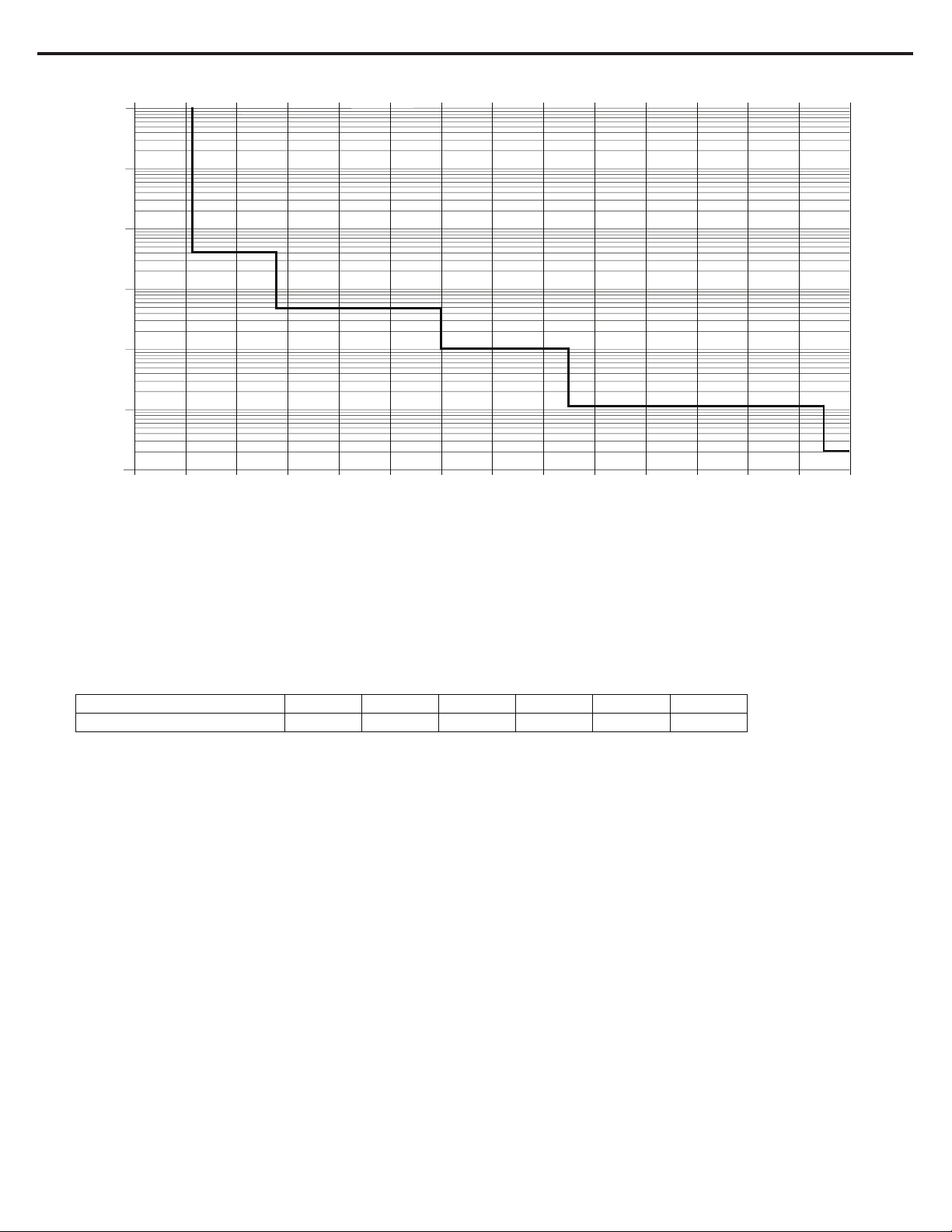
Typical time/current characteristic (T
1000
100
10
1
0.1
trip time in seconds
0.01
0.001
0.8 1 1.2 1.4 1.6 1.8 2 2.2 2.4 2.6 2.8 3 I
= +23 °C, UB = DC 24 V)
amb
SC
times rated current
ISC - short circuit current
Temperature factor / continuous duty
The time/current characteristic depends on the ambient temperature. In order to determine the max. load current,
please multiply the current rating with the temperature factor and consider the factor for side-by-side mounting.
Temperature factor table:
Please note
- When mounted side-by-side, the devices can carry max. 80 % of their rated load or a different rating has to be selected.
- With high temperatures, the load current warning threshold “warn limit typically 0.9 x I
with the temperature factor.
- Selection of current rating of the circuit protector ≤ rating of power supply.
” will be reduced in accordance
N
Publication 1694-IN001D-EN-E - August 2020 DIR 10005708550 (Version 03)
Page 7
Installation Instructions: Bulletin 1694 Electronic circuit protection for 24V DC with IO-Link
Catalog Code
Description
1694-PMD110
Electronic Circuit Protection, Protection Module, IO-Link, 1-Channel, Fix Current, 10A
1694-PMD18
Electronic Circuit Protection, Protection Module, IO-Link, 1-Channel, Fix Current, 8A
1694-PMD211
Electronic Circuit Protection, Protection Module, IO-Link, 2-Channels, Fix Current, 1A, 1A
1694-PMD211-CL2
Electronic Circuit Protection, Protection Module, IO-Link, 2-Channels, Fix Current, 1A, 1A, Class 2
1694-PMD222
Electronic Circuit Protection, Protection Module, IO-Link, 2-Channels, Fix Current, 2A, 2A
1694-PMD222-CL2
Electronic Circuit Protection, Protection Module, IO-Link, 2-Channels, Fix Current, 2A, 2A, Class 2
1694-PMD233
Electronic Circuit Protection, Protection Module, IO-Link, 2-Channels, Fix Current, 3A, 3A
1694-PMD233-CL2
Electronic Circuit Protection, Protection Module, IO-Link, 2-Channels, Fix Current, 3A, 3A, Class 2
1694-PMD244
Electronic Circuit Protection, Protection Module, IO-Link, 2-Channels, Fix Current, 4A, 4A
1694-PMD244-CL2
Electronic Circuit Protection, Protection Module, IO-Link, 2-Channels, Fix Current, 4A, 4A, Class 2
1694-PMD266
Electronic Circuit Protection, Protection Module, IO-Link, 2-Channels, Fix Current, 6A, 6A
1694-PMD2A10
Electronic Circuit Protection, Protection Module, IO-Link, 2-Channels, Adjustable Current, 1A to 10A
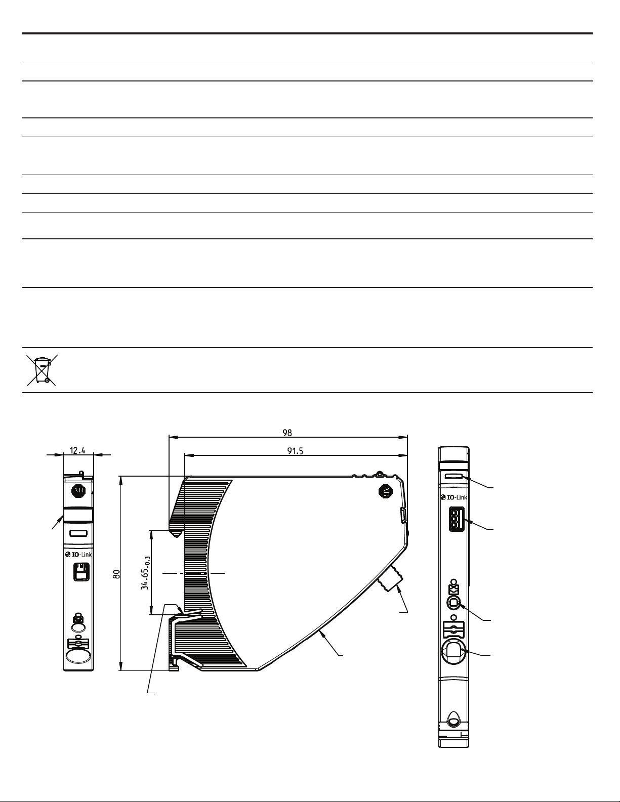
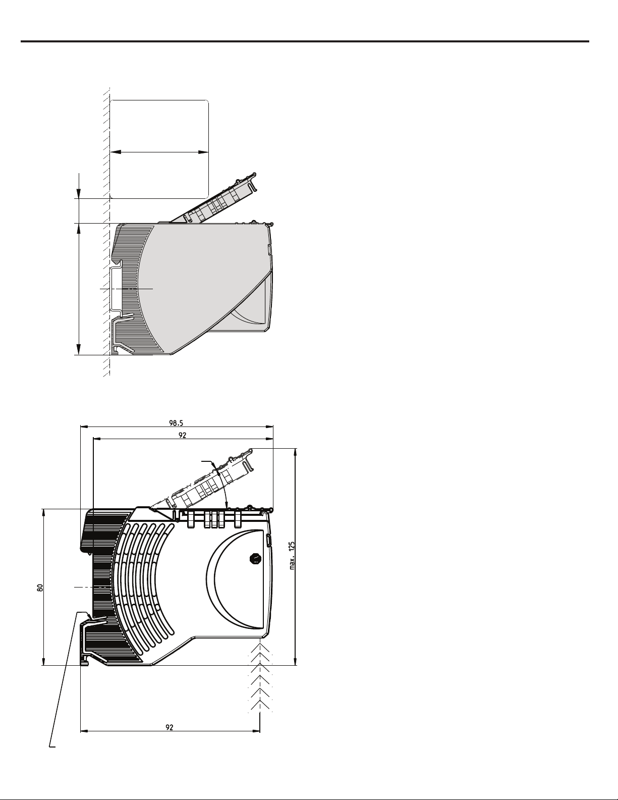
7
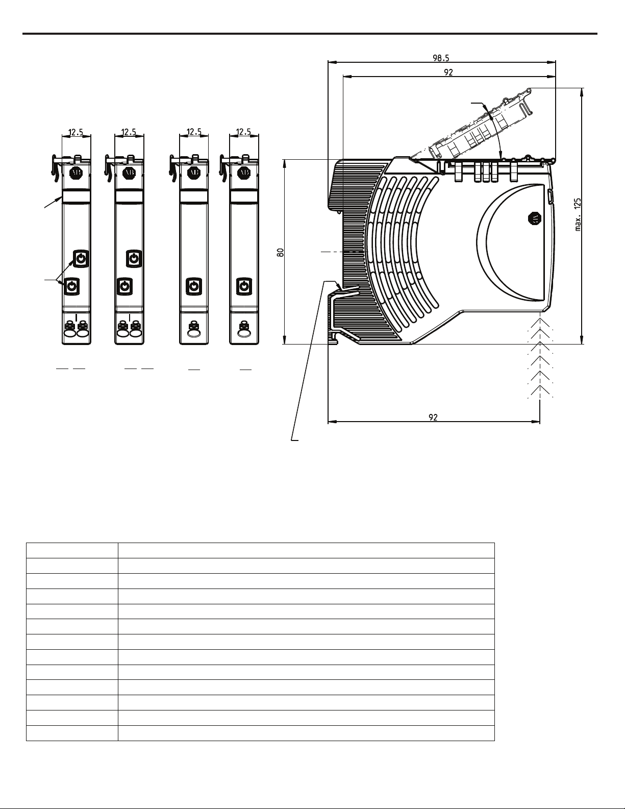
Dimensions 1694-PMD*
Contact arm
1694-PM2
DC24V
Class 2
Marker
xA
xA
2.1 2.2 2.1 2.1 2.12.2
LOAD + LOAD + LOAD + LOAD +
Button for ON / OFF or Reset
with integrated status indication (LED)
1694-PM2
DC24V
xA
xA xAxA
1694-PM1
DC24V
Class 2
1−channel2−channel
1694-PM1
DC24V
snap−on socket for DIN rail EN 60715−35x7.5
Small opening above the screwdriver insert (marked as 2.1 and 2.2) = voltage measuring point.
Larger opening under the screwdriver insert (marked as LOAD +) = wire connection area.
General recommendation for all 1694 modules installation.
For installation instructions please refer to item: Mounting on or removing of 1694-* from symmetrical rail (Page 11)
CAT 1694−PMDxy−zzz SER X
Protection Module IO xxxA xxx
Allen-Bradley
Instalation area
Operating area
Product selection list - 1694-PMD*
Publication 1694-IN001D-EN-E - August 2020 DIR 10005708550 (Version 03)
Page 8
Installation Instructions: Bulletin 1694 Electronic circuit protection for 24V DC with IO-Link
8
2. Bulletin 1694. Power Feed 1694-PFD1244 with IO-link communication
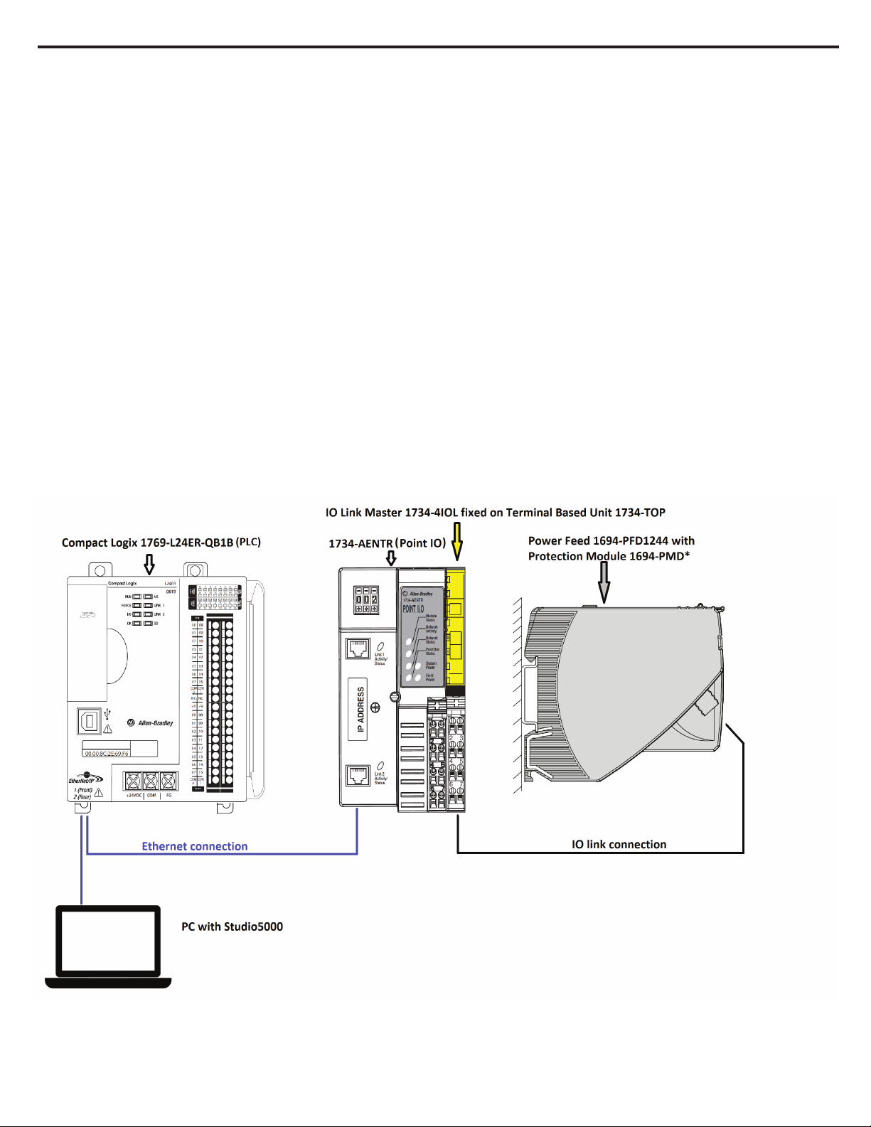
The 1694-PFD1244 Power Feed module receives the DC 24 V supply voltage, e.g. from a switched mode power supply, and distributes it to the mounted circuit
protectors via the integral connector arm of the 1694-PMD. Build-in LED provides information about setup status. Build-in IO-Link communication offers control
and monitoring by Logix Controller of each attached electronic circuit protection module 1694-PMD1244. One IO-Link Power Feed can control max 16
channels.
• Main Communication features:
• Current monitoring for each attached channel
• Voltage monitoring foe each attached channel
• Input voltage monitoring
• Statistics for each attached output channel
◦ Max, min, average current value
◦ Max, min, average voltage vale
• Remote control,
◦ Remote switch ON and switch OFF
◦ Remote trip reset
◦ Channel monitoring parameters change (warning limits)
◦ Trip current limit change for adjustable module (1694-PMD2A10)
• Error massaging.
◦ Protection module errors massaging
◦ Power feed errors massaging
• Last trip information for each channel.
◦ Trip counter
◦ Last trip reason
◦ Trip current
Provided features significantly helps for quick troubleshooting.
User need to use IO-Link master in the setup to build communication capable configuration
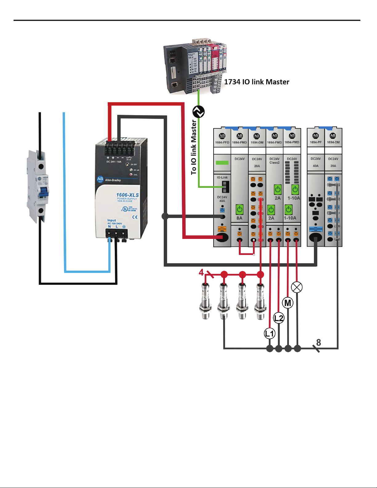
Sample schematic data connection of IO-Link bulletin 1694 devices to ethernet network and Logix Controller
Publication 1694-IN001D-EN-E - August 2020 DIR 10005708550 (Version 03)
Page 9

9
Installation Instructions: Bulletin 1694 Electronic circuit protection for 24V DC with IO-Link
2.1. 1694-PFD1244 Power Feed Module
Technical data (Tamb = +23 °C, UB = DC 24 V)
Operating voltage UB
Operating current IB
Reverse polarity protection Yes, without load
Closed current I0 normal condition: typically 20 mA
Circuit protectors can be mounted
side-by-side
1694-PMD1* 1-channel or
1694-PMD2* 2-channels or
1694-PMD2A10 2-channels
Visual status indication
by means of LED:
DC 24 V (min. 18 V, max. 30 V)
(no battery-buffered applications)
Max. 40 A
max. 16 pieces
Green: Faultless operations
Blinking Independent operations
green:
Red: Critical Anomaly
Orange Uncritical Anomaly (communication available)
Blinking Uncritical Anomaly (communication not available)
Orange
OFF: Device switched off.
For additional information about LED singling related to IO-Link communication please refer to chapter:
Signaling of operating conditions on 1694-PFD1244 Power Feed Module (Page 17).
IO-Link Connection 3 pins communication interface to IO-Link master.
For more information please refer to chapter: IO-Link connector description (Page 16).
General data 1694-PFD1244
Housing material
Mounting method
Ambient temperature (T
Storage temperature -30°...+70 °C
Mounting temperature +5°… +60°C
Corrosion 96hrs. in 5% salt mist to IEC 60068-2-11 test Ka
Humidity: 96 hrs / 95% RH RH/40 °C to IEC 60068-2-78-Cab climate class 3K3 to EN 60721
Vibration resistance 3 g, test to IEC 60068-2-6 test Fc
Degree of protection
terminal
EMC requirements
(EMC Directive, CE Logo)
) -25°...+60 °C (without condensation, cf. EN 60204-1)
amb
plastic
symmetrical rail to EN 60715-35x7.5
IEC 60529, DIN VDE 0470
IP20
Emitted interference: EN 61000-6-3
Noise immunity: EN 61000-6-2
Insulation co-ordination
(IEC 60934)
Dielectric strength max. DC 30 V (load circuit)
0.5 kV / pollution degree 2
Publication 1694-IN001D-EN-E - August 2020 DIR 10005708550 (Version 03)
Page 10
10
Insulation resistance
Installation Instructions: Bulletin 1694 Electronic circuit protection for 24V DC with IO-Link
n/a, only electronic disconnection
(OFF condition)
Terminals LINE+
Push-in terminal PT 10
0.5mm2 to 10mm2, flexible
AWG20 – AWG8 stranded
wire stripping length
18mm
Terminals 0V
Push-in terminal PT 2.5 (0V)
0.14mm2 to 2.5mm2, flexible
AWG24 – AWG14 stranded
wire stripping length
8mm to 10mm
Dimensions (h x w x d) 12.5 x 80 x 98.5 mm
Weight approx. 56 g
Conformity and approvals for 1694-PFD1244 with 1694-PMD*
Conformity CE Marking
Approvals UL 2367 RA File # E350272 current rating range: 1A… 10A
China RoHS
WEEE
Morocco EMC
cULus508 RA File # E56639 current rating range: 1A… 10A
listed
At the End of its life, this equipment should be collected separately from any unsorted municipal waste.
Dimensions 1694-PFD1244
1694-PFD
Marker
L+
C/Q
L-
X81
DC24V
40A
0V
LINE +1
snap-on socket for rail EN 60715-35x7.5
CAT 1694-PFD1244 SER X
Power Feed IO 40A
Allen-Bradley
connector
3-pole
view: X
view: X
L+
C/Q
L-
X81
DC24V
40A
0V
+ 1
LINE
status indication
LED
IO-link master
COM
interface
bushing 1 (L+)
bushing 2 (C/Q)
bushing 3 (L-)
0V DC
LINE + 1
DC 24V - 40A
Publication 1694-IN001D-EN-E - August 2020 DIR 10005708550 (Version 03)
Page 11
11
Installation Instructions: Bulletin 1694 Electronic circuit protection for 24V DC with IO-Link
Configuration example
Module configuration in sample schematic diagram
Starting from left position:
• 1694-PFD1244
• 1694-PMD18
• 1694-DM1L2
• 1694-PMD222-CL2
• 1694-PMD2A10
• 1694-PF1G4
• 1694-DM3G2
Publication 1694-IN001D-EN-E - August 2020 DIR 10005708550 (Version 03)
Page 12
Installation Instructions: Bulletin 1694 Electronic circuit protection for 24V DC with IO-Link
12
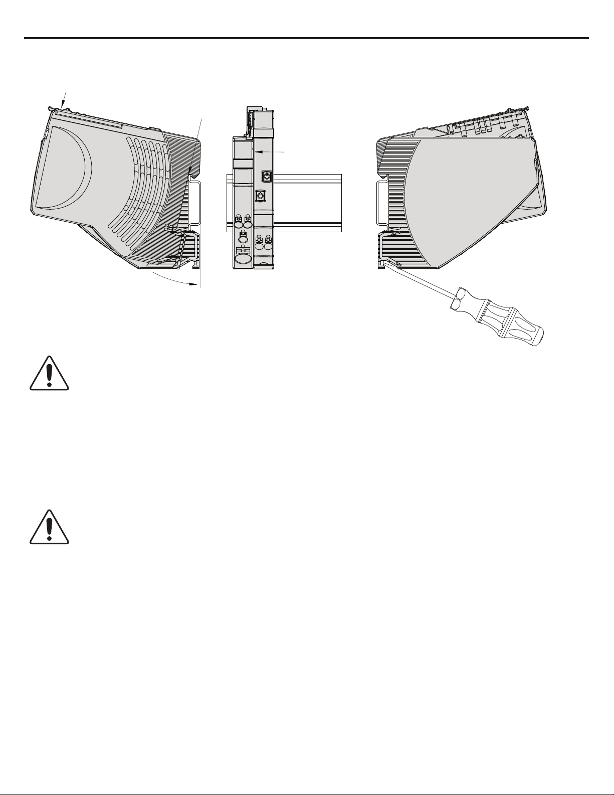
Mounting on or removing of 1694-* from symmetrical rail
Connector arm
can be closed
Push 1694 PM...
towards rail
Mount 1694 PM...
side-by-side
with 1694 PF…
Latch on enclosure
downwards
Remove 1694 PM... from rail
Unlatch with srewdriver,
tilt upwards and remove
(connector arm can be closed)
Please note
Sliding on DIN rail is not permitted.
Open connector arm carefully to avoid damage
General recommendation for all 1694 modules installation.
Screwdriver for installation:
- blade-style screwdriver size 1 for smaller Push-in terminal (PT 2.5) inserts
- blade-style screwdriver size 4 for larger Push-in terminal (PT 10) inserts
Mounting position:
- horizontal mounting position is preferred
Hot swap of circuit protectors is not permitted
Opening under load can damage the device or cause undefined system conditions.
The electronic circuit protection module can at any time be mounted side by side with a supply module or an existing system.
Opening the connector arm is only permitted in the OFF (No input voltage) condition. After plugging in a circuit protector, it will automatically be identified
and parameterized if parameters are available for the slot. During this procedure, the cyclical data will be marked as invalid for a short period of time.
Publication 1694-IN001D-EN-E - August 2020 DIR 10005708550 (Version 03)
Page 13
Installation Instructions: Bulletin 1694 Electronic circuit protection for 24V DC with IO-Link
13
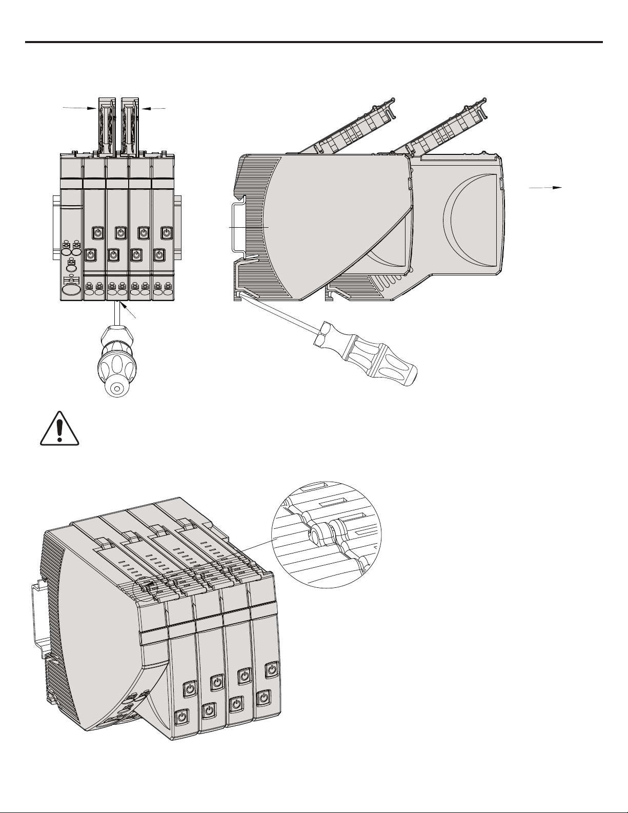
Removing 1694-* devices from DIN rail
Open connector
arm
Open connector
arm
Pull out at right
angles to the rail
Unlatch with screwdriver
Caution
:
Exchange/disassembly only in dead-voltage condition! Potentials will be interrupted.
Locked connector arms of 1694-PM…
Connector arms can
be sealed with
enclosure
Publication 1694-IN001D-EN-E - August 2020 DIR 10005708550 (Version 03)
Page 14
14
Installation Instructions: Bulletin 1694 Electronic circuit protection for 24V DC with IO-Link
Distance between cable duct and connector arm of 1694-*
60
80 15
Installation area – operating area for 1694-*
Contact arm
ConformityConformity
ConformityConformity
CAT 1694−PMxyy−zzz SER X
Protection Module xxxA xxx
Allen-Bradley
snap−on socket for rail EN 60715−35x7.5
Publication 1694-IN001D-EN-E - August 2020 DIR 10005708550 (Version 03)
Instalation area
Operating area
Page 15

15
Installation Instructions: Bulletin 1694 Electronic circuit protection for 24V DC with IO-Link
3. IO-Link technology review
Please note: This is a very short overview of IO-Link technology. For more details please refer to IO-Link specification published on
IO-Link community webpage https://io-link.com.
What is IO-Link technology?
The IO-Link technology is an open point-to-point communication standard and was launched as (IS) IEC 61131-9. IO-Link is now the globally
standardized technology developed initially mainly for sensor and actuator communication with a field bus system. This technology provides
benefits to both OEMs and End Users.
IO-Link provides communications-capable devices to the control level by a cost-effective point-to-point connection. IO-Link provides a
point-to-point link between the I/O module and device that is used for transferring detailed diagnostics, device identity information, process
data, and parameterization.
IO-Link communication is based on a structure in which the master controls the interface access to the IO-Link device. The option of using the
intelligence that is integrated into the IO-Link device provides the user with new commissioning methods. Benefits range from reduced
installation time during startup to increased diagnostics over the lifetime of the machine. Benefits of IO-Link technology include:
• Reduced inventory and operating costs
• Increased uptime/productivity
• Simplified design, installation, set up and maintenance
• Enhanced flexibility and scalability
• Detailed diagnostic information for preventative maintenance
Why IO-Link?
IO-Link Offers a Full Range of Advanced Features and Functions
Seamless Integration
• Forward and backward compatible,
• No special cables required
• Connectivity options remain the same
• Access IO-Link functionality by simply connecting an IO-Link enabled device to an IO-Link master
Real-time Diagnostics and Trending
• Real-time monitoring of the entire machine down to the IO-Link device level
• Optimized preventative maintenance—identify and correct issues before Anomaly can occur
• Detect IO-Link device malfunctions/Anomalies
IO-Link Device Health Status
• Real-time monitoring helps ensure that IO-Link devices are operating correctly
• Detect damaged IO-Link device and pinpoint their exact location for quick troubleshooting through Application Specific Name parameter
Device Profiles and Automatic Device Configuration
• IO-Link technology provide user with quick IO-Link device configuration within minutes instead of hours,
Descriptive tags
• Faster programming during initial setup
• More efficient troubleshooting process-data tags are named based on the information they provide
• Easily monitor device data though intuitive tag names
How IO-Link works?
IO-Link delivers data over the same standard field cabling used today. By connecting an IO-Link device to an IO-Link master, the field-device
data and diagnostics are accessible. So go beyond detecting products on the machine—now the health of the machine can be MONITORED
as it runs.
Publication 1694-IN001D-EN-E - August 2020 DIR 10005708550 (Version 03)
Page 16

16
IO-Link Data Types
There are four data types available through IO-Link:
Installation Instructions: Bulletin 1694 Electronic circuit protection for 24V DC with IO-Link
Process Data (cyclic data)
The process data of the devices are transmitted cyclically in a data frame in which the size of the process data is specified by the
device. Depending on the device, 0...32 bytes of process data are possible (for each input and output). The consistency width of the
transmission is not fixed and is thus dependent on the master.
Value Status (cyclic data)
The value status indicates whether the process data is valid or invalid. The value status can be transmitted cyclically with the process data.
Device Data (acyclic data)
Device data supports device-specific configurable parameters, identification data, and diagnostic information. They are exchanged
acyclically and at the request of the IO-Link master. Device data can be written to the device (Write) and read from the device (Read)
Events (acyclic data)
When an event occurs, the device signals the presence of the event to the master. The master then reads out the event. Events can
be error messages and warnings/maintenance data. Error messages are transmitted from the device
3.1. Accessing IO-Link Data
Cyclic Data
To exchange the cyclic process data between an IO-Link device and a controller, the IO-Link data from the IO-Link master is placed on the
address ranges assigned beforehand. The user program on the controller accesses the process values using these addresses and processes
them. The cyclic data exchange from the controller to the IO-Link device is performed in reverse.
Acyclic data (Non-cyclic data)
Acyclic data, such as device parameters or events, are exchanged using a specified index range. The controller accesses these using Explicit
Messaging. The use of the index ranges allows targeted access.
4. IO-Link connector description used for 1694-PFD1244
IO-Link connector
Connection to IO-Link bus system.
This plug is delivered with Power Feed device.
Push-in terminals
Recommended cable parameters:
Cable length: max 20m
Cross section: 0.25 mm² to 0.5 mm²
stripping length = 6 mm
The cable does not have to be shielded specially.
Connector 1: IO-Link Terminal + (24V DC)
Connector 2: IO-Link Terminal C/Q (Data Cable to IO-Link master)
Connector 3: IO-Link Terminal L- (GROUND)
Connector 1 and 3 provide the energy for IO-Link control circuit in Power Feed
For wire connection please use 0 size flat-head screwdriver. By inserting the screwdriver into the rectangular openings of the connector plug,
the terminals are opening (for wire insert).
Publication 1694-IN001D-EN-E - August 2020 DIR 10005708550 (Version 03)
Page 17

Installation Instructions: Bulletin 1694 Electronic circuit protection for 24V DC with IO-Link
Operational status
LED button signal
IO-Link communication
System start
Orange (for approx. 1 sec)
Not available
Normal operations
Green
Available
Independent operations
Blinking green
Not available
Critical anomaly detected
Red
Not available
Non-critical anomaly detected
Orange
Available
Non-critical anomaly detected
Blinking orange
Not available
17
5. Signaling of operating status on 1694-PFD1244 Power Feed Module
LED button can signal following channel operational status:
Operating status: System start
When applying the supply voltage, the Power Feed will be initialized. The device will
carry out implemented program memory tests and self-test routines. During this time, a communication via the interfaces is not possible.
When system is starting, this operational status is indicated by orange color of LED for approximately 1 second.
Operational status: Normal operations.
If there is no fault and a connection to IO-Link master is established, the Power Feed will be into the operating mode “faultless operation”. The
parameters will be transmitted from the IO-Link master to the Power Feed and be saved there. Subsequently they will be forwarded to the
electronic circuit protectors. The configuration data and the parameters will be exchanged as non-cyclical data between the IO-Link master
and the Power Feed.
Operational status: Independent operations
If no connection to the IO-Link master is recognized after the supply voltage was applied, the module will change into the operating mode
“independent operations”.
The parameters stored in the Power Feed will be transmitted to the Protection Modules.
This operational mode will appear always when communication to IO-Link master is interrupted.
This operation mode will disappear always when communication to IO-Link master is restored.
If there is a connection between the Power Feed and IO-Link master and there is no critical anomaly, the Operational status: “independent
operations” will be quitted.
The behavior of the Power Feed and Protection Modules can be defined in the event of a communication interruption to IO-Link master. User
can choose if Protection Modules should work continuously or be switched OFF in case of communication lost.
Operational status: Critical anomaly.
If an anomaly is detected during the self-test routines, the Power Feed will change into status: “Critical anomaly”. In the event of a critical
anomaly this operating mode can only be discontinued re-starting the device and it prevents the data exchange via the interfaces. If the
Power Feed is in Critical anomaly status, then no communication is possible with control unit. The Protection Modules cannot be controlled by
it and remain OFF.
Operational status: Non-critical anomaly.
If there are invalid data or configuration data are not available, the Power Feed will go into Non-Critical anomaly mode. This mode allows only
restricted non-cyclical data exchange. Cyclical data exchange is prevented. Non-critical anomaly mode will be left when user setup the correct
module, slot parameters and configuration. The protection modules remain OFF.
Publication 1694-IN001D-EN-E - August 2020 DIR 10005708550 (Version 03)
Page 18

Installation Instructions: Bulletin 1694 Electronic circuit protection for 24V DC with IO-Link
Operational status
LED button signal
Condition of load output
Device switched off by means of ON/OFF
momentary switch or no operating voltage.
Dark
OFF
and OFF by IO-Link in PLC Control mode.
Orange
OFF
and IO-Link in PLC Control mode.
Green
ON
Load current warning limit reached.
Blinking green/orange
ON
Channel Overload detected.
Orange
ON
Trip by short circuit or overload.
Red
OFF
Low input voltage detected.
Red
OFF
18
6. Signaling of operating status on 1694-PMD* Protection Modules
LED button can signal following channel operational status:
Channel ON by momentary switch
Channel ON by momentary switch
Pay attention on specific signaling in PLC Control mode.
Publication 1694-IN001D-EN-E - August 2020 DIR 10005708550 (Version 03)
Page 19

19
Installation Instructions: Bulletin 1694 Electronic circuit protection for 24V DC with IO-Link
7. Installation and configuration of 1694-PFD1244 and 1694-PMD* in Studio5000
7.1. AOP Installation
Add-on Profiles are files that users add to their Rockwell Automation® library. These files contain the pertinent information for configuring a
device that is added to the Rockwell Automation network. The Add-on Profile simplifies the setup of devices because it presents the necessary fields in an organized fashion. The Add-on Profile allows for set up and configuration of systems in a quick and efficient manner. The
Add-on Profile is a folder that contains numerous files for the device. It comes as an installation package.
Before start making a project in Studio5000 it is recommended to verify if proper and newest versions of AOP files are installed. In this
example you will need AOP for Point IO 1734-AENTR and IO-Link Master 1734-4IOL.
If the AOP is required to be downloaded and installed, then please use following link:
https://download.rockwellautomation.com/esd/download.aspx?downloadid=addonprofiles (registration required)
Extract the AOP zip file, open the folder, and execute the “MPSetup” application file.
7.2. Creating a Project
Following steps shows how to create simple configuration with 1694-PFD1244 and 1694-PMD* modules.
To begin a new project in Studio 5000, follow these steps.
1. Double Click the icon of Studio5000. In this example version 32 of Studio5000 is used.
2. Click New Project
7.3. Adding a Controller
3. To program the controller, select the controller that is used. In this example, it is used the “1769-L24ER-QB1B” CompactLogix.
4. After selecting the controller, name the project and click “Next” in the example, the project name is “ECP”.
Publication 1694-IN001D-EN-E - August 2020 DIR 10005708550 (Version 03)
Page 20

20
Depending on Studio5000 version you might be requested to set up some additional parameters as shown on below picture. Chose what you
need and press “Finish”.
Installation Instructions: Bulletin 1694 Electronic circuit protection for 24V DC with IO-Link
7.4. Adding a Point IO (Ethernet Adapter)
5. Add Point IO to the project. In this project 1734-AENTR point IO is used.
To add device to the project, Studio500 must by in “Offline” mode as shown in the picture below
6. In the controller organizer tree, find Ethernet under I/O Configuration and right-click to “add new module”.
Publication 1694-IN001D-EN-E - August 2020 DIR 10005708550 (Version 03)
Page 21

21
7. The module window pops up and shows the available modules. Use the filter to
select “1734-AENTR” Point IO module and click “Create” button.
8. Name the Ethernet adapter (in this example we used name “Point IO”), set the chassis size, check the module revision, and set up the
adapter IP address. Click OK and Close.
Installation Instructions: Bulletin 1694 Electronic circuit protection for 24V DC with IO-Link
9. The 1734 AENTR module is now visible in the Controller Organizer tree in the Ethernet section.
Publication 1694-IN001D-EN-E - August 2020 DIR 10005708550 (Version 03)
Page 22

Installation Instructions: Bulletin 1694 Electronic circuit protection for 24V DC with IO-Link
22
7.5. Adding an IO-Link Master
10. Now IO-Link Master module must be added. Make sure that the controller is offline prior you start configuration. In the Controller Organizer tree, find Ethernet under I/O Configuration and right-click to “add new module” on Ethernet adapter 1734-AENTR.
11. The module window pops up and shows the available modules. Use the filter to select “1734-4IOL” module and click “Create” button.
Publication 1694-IN001D-EN-E - August 2020 DIR 10005708550 (Version 03)
Page 23

Installation Instructions: Bulletin 1694 Electronic circuit protection for 24V DC with IO-Link
23
12. Another window appears to show the IO-Link Configuration screen.
Close selection pups up window if still visible.
13. The IO-Link Master can now be configured. To configure the device, a device specific IODD (IO Device Description) file is required. The
next steps show how to register the IODD file
7.6. Registration of IODD file for Power Feed 1694-PFD1244
To initialize a device on an IO-Link Master, register the IODD of the device. The IO Device Description (IODD) files contain the information
that is related to the device, integrated into the system environment.
By default, the IODDs are already located in the AOP Library.
If the IODD file for the 1694-PFD1244 cannot be located in the library, it can be downloaded from:
http://compatibility.rockwellautomation.com/Pages/MultiProductDownload.aspx.
And loaded manually to Studio5000. Once the IODD is registered, there is no need to register the IODD again unless it is manually deleted
from the Master Tree.
14. Double-click the 1734-4IOL in the Controller Organizer tree in the Ethernet section
15. Properties window will be opened. Click IO-Link on the left side of the window. Screen as shown below will be displayed.
Publication 1694-IN001D-EN-E - August 2020 DIR 10005708550 (Version 03)
Page 24

24
16. Right-click on the left section of the screen where the channel information is located and click “Register IODD”.
17. Select the IODD file that is needed for the device being configured and double click.
If there is no proper IODD file on the list, then press button “Register IODD” and select folder and file previously downloaded to your PC.
Selected IODD will be shown on the list.
Installation Instructions: Bulletin 1694 Electronic circuit protection for 24V DC with IO-Link
18. Then Click “Exit”
19. The IODD registration is completed.
Publication 1694-IN001D-EN-E - August 2020 DIR 10005708550 (Version 03)
Page 25

25
Installation Instructions: Bulletin 1694 Electronic circuit protection for 24V DC with IO-Link
7.7. Connect the 1694-PFD1224 to the IO-Link Master
Once the IODD file is registered, the device must be connected to the IO-Link master. The controller must always be offline to add a device to
the IO-Link Master.
20. Right-click the channel number where the power feed for electronic circuit protection is configured and click “Change”
21. Change Channel Configuration window will appear. Then click “…” on right side of the table.
Caution: Once you click “Create” you might be
required to wait longer time for configuration update.
In this time Studio5000 might not react.
Publication 1694-IN001D-EN-E - August 2020 DIR 10005708550 (Version 03)
Page 26

26
23. Click “Yes” to accept changes in module definition.
24. Press “Apply” and “OK” to accept configuration.
25. In IO-Link Tab, check if Data Storage mode for IO-Link channel is established as “Enable ADC”. This is not mandatory but might make
configuration process easier. If different mode is chosen, then user cannot see and cannot change device parameters values in offline mode.
Installation Instructions: Bulletin 1694 Electronic circuit protection for 24V DC with IO-Link
Caution: you might be required to wait longer time
for configuration update. In this time Studio5000
might not react.
Now you are almost ready to go online to download the project to controller.
Prior going online you must set up communication path
7.8. Download the Project to Allen-Bradley Logix Controller
26. Setup controller communication path. Click COMMUNICATION on the toolbar and then “Who Active”.
27. Select the controller that is being used for the project. In this example we are using “1769-L24ER-QB1B” CompactLogix. Once controller
is selected, click “Set Project Path” and then “Go online” to start communication.
Publication 1694-IN001D-EN-E - August 2020 DIR 10005708550 (Version 03)
Page 27

Installation Instructions: Bulletin 1694 Electronic circuit protection for 24V DC with IO-Link
27
28. Download the project to controller. Click “Download” and then confirm downloading on the next window.
29. Project is loaded to the controller.
Publication 1694-IN001D-EN-E - August 2020 DIR 10005708550 (Version 03)
Page 28

Installation Instructions: Bulletin 1694 Electronic circuit protection for 24V DC with IO-Link
28
7.9. Exploring the 1694-PMD1244 Parameters in AOP
To display parameters of Power Feed 1694-PFD1224 and Protection Modules 1694-PMD* in AOP you need to open IO-Link Master AOP.
Do to that:
1. in the Controller Organizer tree, find Ethernet under I/O Configuration and double click on IO-Link Master)
2. Properties window will be opened. Click IO-Link on the left side of the window on IO-Link description.
3. Then in IO-Link section click on proper channel of IO-link Master where 1694-PFD1244 module is installed (in this case this is Ch0) and
click on device attached to this channel.
Publication 1694-IN001D-EN-E - August 2020 DIR 10005708550 (Version 03)
Page 29

29
Tab
Description
Common
Tab
specifications and IO-link IODD Information.
Tab
Provides the device catalog number, series letter, general
and hardware revisions.
Tab
Provides device monitoring parameters for power feed 1694-
Protection device.
Parameter
Tab
offered by 1694 Electronic Circuit Protection system.
Diagnosis Tab displays the diagnostics parameters. Those
Factory Setting, etc.
4. IO-Link overcurrent protection system parameters will be displayed
The 1694-PMD1244 offers five different tabs to describe the device functionality and operations. These tabs are:
Installation Instructions: Bulletin 1694 Electronic circuit protection for 24V DC with IO-Link
Identification
Observation
Diagnosis
Tab
Provides general product information about the device
product description including the current product firmware,
PMD1244 and each channel controlled by Electronic Circuit
Displays and allows you to change the device parameters
parameters facilitate troubleshooting if device does not work
correctly. In this tab, user can find features common for the all
protection channels such as: Device Access Lock, Restore
Publication 1694-IN001D-EN-E - August 2020 DIR 10005708550 (Version 03)
Page 30

30
Tab
Description
Vendor
Provides the vendor name assigned to Vendor ID.
Vendor Text
Field used to describe additional product information. In this case it
displays product Internet webpage address.
Vendor ID
Describes the vendor ID of the manufacturer of the product as
vendor’s identifier and is assigned by the IO-Link Consortium.
URL
Displays the vendor URL.
Device
Provides the specific catalog number of the product.
Description
This parameter displays the product description.
Device ID
The parameter Device ID contains the vendor internal unique
Automation.
Revision
Displays the IO-Link implemented revision of protocol supported by
Hardware
Revision
Displays the device hardware revision number. To confirm the latest
version of HW check value in Identification tab
Firmware
Revision
Displays the device firmware revision number. To confirm the latest
version of FW check value in Identification tab
Bitrate
Displays the IO-Link implemented communication speed supported
by the device.
Minimum
Cycle Time
This is device parameter to inform the master about the shortest
cycle time supported by the device. Value is given in microseconds
IODD
Displays an information about the IODD which has been used to
configure the IOLD
SIO mode
Displays the information whether the IOLD support the SIO
(Standard Input and Output).
Document
Version
Displays information about the IODD’s version which has been used
to configure the IOLD
Date of
Creation
This field displays date when the IODD file has been CRC stamped
Installation Instructions: Bulletin 1694 Electronic circuit protection for 24V DC with IO-Link
7.9.1. Common Tab
Common tab contains the following device information:
IO-Link
designated in the IO-Link consortium. This is worldwide unique
device’s identifier. The Device ID is assigned by the Rockwell
the device.
Publication 1694-IN001D-EN-E - August 2020 DIR 10005708550 (Version 03)
Page 31

31
Parameter
Description
- Device Information Section
Vendor Name
Provides the vendor name of the product. For 1694PFD1244 this is Allen-Bradley.
Product Name
Provides the product catalog number information. For this
device this is 1694-PFD1244.
Product ID
Provides product catalog number information with series
letter. For this device is: 1694-PFD1244 Series A.
Product Text
Provides product (Power Feed) description.
Serial Number
Provides Power Feed serial number as unique numeric
value.
- User Specific Information Section
Device specific name assigned to device by user for device
populated and is Read/Write).
-
Revision Information Section
Hardware Version
Hardware version of Power Feed 1694-PFD1244 provided
as alphanumeric value
Firmware Version
Firmware version of Power Feed 1694-PFD1244 provided
as numeric value
Installation Instructions: Bulletin 1694 Electronic circuit protection for 24V DC with IO-Link
7.9.2. Identification Tab
The Device Information shows us the Vendor Name, Product Name, Product Text, Product ID, and Serial Number of the exact device that is
configured.
These fields automatically populate according to the device information. These fields are read-only (RO).
The User Specific Information contains the Application-Specific Name (ASN) where you can name the device with a unique text string for
identification. The ASN allows a unique identity of each device. These fields can be custom (that is populated and is read/write).
Identification tab contains the following device information:
Application Specific
Tag
identification. The Application Specific Tag allows a unique
identity of each device. These fields can be custom (that is
Publication 1694-IN001D-EN-E - August 2020 DIR 10005708550 (Version 03)
Page 32

Installation Instructions: Bulletin 1694 Electronic circuit protection for 24V DC with IO-Link
Parameter
Description
-
System Measurements Section
Process Data
In.InputVoltage
Provides power supply voltage value (line side). Unit V.
-
Channels Measurements
-
Measurements of ChXX (XX=01...16)
ChXX Voltage
Provides channel XX voltage value. Unit V.
Process Data
In.ChXXCurrent
Provides channel XX current value. Unit A.
-
Device Monitoring ChXX (XX=01…16)
- Device Details
Provides type of each type of Electronic Overcurrent Protection
- Adjustable current threshold module.
.Hardware Version
Firmware version of attached Overcurrent Protection Module
for channel XX control. This is provided as numeric value.
Software (Firmware) version of attached Overcurrent Protection
value.
.Serial Number
Serial number of attached Overcurrent Protection Module for channel
XX control. This is provided as unique numeric value.
32
7.9.3. Observation Tab
The Device Information shows us the Vendor Name, Product Name, Product Text, Product ID, and Serial Number of the exact device that is
configured.
These fields automatically populate according to the device information. These fields are read-only (RO).
The User Specific Information contains the Application-Specific Name (ASN) where you can name the device with a unique text string for
identification. The ASN allows a unique identity of each device. These fields can be custom (that is populated and is read/write).
Identification tab contains the following device information:
Module attached to Power Feed. It can be:
- No Device detected,
.Device Type
- 1-Channel module,
- 2-Channel module,
.Software Version
Module for channel XX control. This is provided as numeric
Publication 1694-IN001D-EN-E - August 2020 DIR 10005708550 (Version 03)
Page 33

Installation Instructions: Bulletin 1694 Electronic circuit protection for 24V DC with IO-Link
.Trip Counter
Provides number of trips for channel XX counted since first
device use or last reset.
.Last Trip Type
Provides reason of last trip for channel XX. Variable can
- Device Internal Fault
- Statistics
.Minimum Current
Provides value of lowest measured current for channel XX
since first power ON or last device/statistics reset. Unit A.
.Maximum Current
Provides value of highest measured current for channel XX
since first power ON or last device reset. Unit A.
.Average Current
Provides value of average measured current for channel XX
since first power ON or last device reset. Unit A.
.Minimum Voltage
Provides value of lowest measured voltage for channel XX
since first power ON or last device reset. Unit V.
.Maximum Voltage
Provides value of highest measured voltage for channel XX
since first power ON or last device reset. Unit V.
.Average Voltage
Provides value of average measured voltage for channel XX
since first power ON or last device reset. Unit V.
33
display following massages:
- Not Triggered
- Channel Short Circuit
- Channel Overload
Remarks to statistical data:
- Power ON/OF cycle does not reset the statistical data.
- Statistical values are calculated only if channel is ON.
Publication 1694-IN001D-EN-E - August 2020 DIR 10005708550 (Version 03)
Page 34

34
Parameter
Description
- System Configuration
.Output State During
Allows user to define the Electronic Overcurrent Protection System
OFF when communication is failed.
.Power Save
User can setup power save mode for Electronic Overcurrent Protection
System. If Power Save mode in ON then LEDs shining is reduced.
-
Parameters ChXX (XX=01…16)
-
Settings
Allows user to define Current Trip Limit value for adjustable
type, then system will refuse this demand. Unit A.
.Warning Limit
Allows user to define current value (warning limit) for channel XX
to 100% of Trip Limit/Nominal current. Unit %.
Installation Instructions: Bulletin 1694 Electronic circuit protection for 24V DC with IO-Link
7.9.4. Parameters Tab
Parameters tab shows parameters that can be changed. User can define in this tab device behavior when communication is lost, warning
limits, trip current, PLC control. This tab provide user with reset functions for memory fault, trip counter, statistical measurements.
Parameters tab contains the following device information:
Communication Fail
.Trip Limit
behavior in case of communication failed.
If value is ON then outputs of all the Circuit Protectors remain in their
current condition when communication is failed.
If value is OFF then outputs of all the Circuit Protectors are switched
Electronic Overcurrent Protection module. When this value is
exceeded in the circuit (channel XX), then device will go into trip
state. For more information please refer to time/current characteristic
and temperature factor table. Parameter Range: 1 to I
(In – Module Nominal Current).
For non-adjustable modules, this value is read only (only for user
reference). If user tries to change this pa
when the LED starts blinking (green / orange). Parameter range: 50%
n.
rameter for non-adjustable
Publication 1694-IN001D-EN-E - August 2020 DIR 10005708550 (Version 03)
Page 35

35
Controller Tag
ON/OFF
OFF
disconnected)
ON
(Green)
If in PLC
.On
Channel status: OFF
is in PLC control mode
Channel status: OFF
using LED button
- Commands
Channel Command: Reset
Trip Counter [Button]
Allows user to reset trip counter for channel XX. If cannel XX is controlled by 2channels module then both channels will be reset.
Channel Command: Reset
[Button]
Allows user to reset minimum value memory of voltage and current statistics for
be reset.
Channel Command: Reset
[Button]
Allows user to reset average value memory of voltage and current statistics for
be reset.
Channel Command: Reset
[Button]
Allows user to reset maximum value memory of voltage and current statistics for
be reset.
Installation Instructions: Bulletin 1694 Electronic circuit protection for 24V DC with IO-Link
Allows user to define if channel XX can be controlled by PLC.
When this parameter is setup as ON channel XX goes into status as described in
below table.
.PLC Control
.PLC Control= OFF
Initial
Channel
XX Status
ON
(Green)
.On relevant bit
value
responsible for
channel XX
Bit=0 Orange
Color of channel
XX LED button
after PLC
Control setup as
ON
.PLC Control= ON
Status of XX
channel after
PLC Control
setup as ON
(load
Remark
Bit=1 Green ON
Control mode,
user pushes
LED button to
switch channel
ON, then device
reaction will
depend on
OFF
(Dark)
Bit=0 or 1 Dark
OFF
(load
disconnected)
relevant bit
value in
Controller Tag
In PLC Control mode user can still control channel XX using LED module button.
Device behavior when LED button is pressed in PLC Control mode is described in
below table.
LED Status Channel status
Orange OFF
Device reaction while LED button is
pressed in PLC control mode = ON
LED status: DARK
PLC cannot control channel even if
LED status: DARK
Green ON
PLC cannot control channel even if
is in PLC control mode
Only user can switch channel ON
Comment: Channel trip reset can be done remotely from PLC independently on PLC
Control mode.
Minimum Value Memory
Average Value Memory
Maximum Value Memory
channel XX. If cannel XX is controlled by 2-channels module then both channels will
channel XX. If cannel XX is controlled by 2-channels module then both channels will
channel XX. If cannel XX is controlled by 2-channels module then both channels will
Publication 1694-IN001D-EN-E - August 2020 DIR 10005708550 (Version 03)
Page 36

36
Installation Instructions: Bulletin 1694 Electronic circuit protection for 24V DC with IO-Link
7.9.5. Diagnosis Tab
This tab provides user with device status information. User can check here potential device system faults and channel faults. In this place
reset to factory settings can be done and reset of all statistical data as well. Here, user can also block device parameter changes to protect
setup against unintended changes.
Diagnosis tab contains the following device information:
Parameter Description
- Device Access Locks
Device Access Locks.Data
Storage Lock
- Device Status
Device Status
Service Function
-
Standard Command: Reset
All Statistics [Button]
Standard Command: Restore
Factory Settings [Button]
By setting this parameter as "True", user can disable overwriting IO-link
device parameters by Data Storage mechanism defined by IO-Link
specification. Rockwell Automation does not recommend to control Data
Storage Lock in device by this parameter. To control Data Storage
mechanism user should use relevant function in IO-Link master settings.
If value is "True" then Data Storage in IO-Link Device is locked
If value is "False" then Data Storage in IO-Link Device is unlocked (can
be updated by IO-Link Master)
Displays the status of device.
- Device is OK.
- Maintenance required: The Process Data are valid, internal
diagnostics indicate that the Device is close to lose its ability
of correct functioning.
- Out of specification: The Process Data are valid, internal
diagnostics indicate that the Device is operating outside its
specified range or environmental conditions.
- Functiona
due to intended manipulations on the Device.
This is summary diagnosis status concerning all devices in the setup.
Provides reset function of all statistics for all protection modules in the
setup.
Provides reset to factory settings function for all devices in the setup.
l check: The Process Data are temporarily invalid
Publication 1694-IN001D-EN-E - August 2020 DIR 10005708550 (Version 03)
Page 37

Installation Instructions: Bulletin 1694 Electronic circuit protection for 24V DC with IO-Link
- Device System Fault
This parameter can provide following massages:
setup.
- Channel Fault
- ChXX Fault ( XX = 01…16)
Fault
This parameter provides massage concerning channel XX fault and can
- Device parameters changed.
Internal Fault
This parameter provides massage concerning channel XX internal fault
- Device is not available
Channel Command:
[Button]
Provides rest function of Internal Fault Memory for all channel ChXX
37
Device System Fault
- System is working normally.
- Fault in Internal Parameter Memory detected. Disconnect and
re-connect the Circuit Protector from Supply Voltage. If
problem persists, please contact Rockwell Automation for
further support.
- Detected Device is not supported.
- Internal communication was interrupted. Either there are no
devices connected or they are not powered.
- Watchdog Timer Reset occurred. Th
Strong Electromagnetic Interference. Try “Reset Error
Memory” command.
is could be caused due to
- The System has found a Fault in the Hardware. Please contact
Rockwell Automation for further support.
This is summary diagnostic information concerning all devices in the
provide following massage types:
- No Fault.
- Device is not available.
- Hardware switch is in OFF position.
- Undervoltage.
- Overheating.
- Output needs Reset.
- Internal Fault.
- Internal Communication Fault - Wrong Frame Length.
- Internal Communication Fault - Wrong Checksum.
Reset Internal Fault Memory
and can provide following massage types:
- No Fault
- Fault in Internal Parameter Memory detected. Disconnect and
re-connect the Circuit Protector from Supply Voltage. If
problem persists, please contact Rockwell Automation for
further support
- Checksum Fault in Parameters Memory. Disconnect and re-
connect the Circuit Protector from Supply Voltage. If problem
persists, please contact Rockwell Au
support
- Checksum Fault in Program Memory. Disconnect and re-
connect the Circuit Protector from Supply Voltage. If problem
persists, please contact Rockwell Automation for further
support
- Checksum Fault in Data Memory. Disconnect and re-connect
the Circuit Protector from Supply Voltage. If problem persists,
please contact Rockwell Automation for further support
- Internal M
Circuit Protector from Supply Voltage. If problem persists,
please contact Rockwell Automation for further support
- Watchdog Timer Reset occurred. This could be caused due to
Strong Electromagnetic Interference. Try “Reset Error
Memory” command
in the setup.
icrocontroller Fault. Disconnect and re-connect the
tomation for further
Publication 1694-IN001D-EN-E - August 2020 DIR 10005708550 (Version 03)
Page 38

Installation Instructions: Bulletin 1694 Electronic circuit protection for 24V DC with IO-Link
- Communication Characteristics
Direct Parameters 1.Min
This parameter shows a device (Power Feed) parameter to inform the
MinCycleTime. (Row 4136)
Direct Parameters 1.Master
This is IO-Link Master parameter and sets up the actual cycle time of a
MinCycleTime. (Row 4136)
Direct Parameters 1.IO-Link
Version ID
Provides IO-Link version supported by Power Feed.
38
Cycle Time
Cycle Time
Master about the shortest cycle time supported by this device (Power
Feed).
Value should be decoded by user according to IO-Link Interface and
System Specification Version 1.1.2. Chapter: MasterCycleTime and
particular port in IO-Link Master.
Value should be decoded by user according to IO-Link Interface and
System Specification Version 1.1.2. Chapter: MasterCycleTime and
Publication 1694-IN001D-EN-E - August 2020 DIR 10005708550 (Version 03)
Page 39

Installation Instructions: Bulletin 1694 Electronic circuit protection for 24V DC with IO-Link
39
8. Device Parameters Details
8.1. Cyclic Data
The IODD file defines the data communication between the IO link master and power feed. In detail these are the status and the load current
of the electronic circuit protectors. In addition, it is possible to switch the devices on or off or reset them in the event of an anomaly. These
parameters are available in Studio5000 Controller Tags. All Cyclic Data are available also using ISDU (Indexed Service Data Unit). Information required to use Cyclic Data in ISDU mode are provided in below table.
Parameter
Name
Index (Dec)
Place in the Index
/ Sub-Index (Dec)
.Ch01Current 40 1 RO 0 0…25.5A (0...255) UIntegerT (RecordT)
.Ch02Current 40 2 RO 0 0…25.5A (0...255) UIntegerT (RecordT)
.Ch03Current 40 3 RO 0 0…25.5A (0...255) UIntegerT (RecordT)
.Ch04Current 40 4 RO 0 0…25.5A (0...255) UIntegerT (RecordT)
.Ch05Current 40 5 RO 0 0…25.5A (0...255) UIntegerT (RecordT)
.Ch06Current 40 6 RO 0 0…25.5A (0...255) UIntegerT (RecordT)
.Ch07Current 40 7 RO 0 0…25.5A (0...255) UIntegerT (RecordT)
.Ch08Current 40 8 RO 0 0…25.5A (0...255) UIntegerT (RecordT)
.Ch09Current 40 9 RO 0 0…25.5A (0...255) UIntegerT (RecordT)
.Ch10Current 40 10 RO 0 0…25.5A (0...255) UIntegerT (RecordT)
.Ch11Current 40 11 RO 0 0…25.5A (0...255) UIntegerT (RecordT)
.Ch12Current 40 12 RO 0 0…25.5A (0...255) UIntegerT (RecordT)
.Ch13Current 40 13 RO 0 0…25.5A (0...255) UIntegerT (RecordT)
.Ch14Current 40 14 RO 0 0…25.5A (0...255) UIntegerT (RecordT)
.Ch15Current 40 15 RO 0 0…25.5A (0...255) UIntegerT (RecordT)
.Ch16Current 40 16 RO 0 0…25.5A (0...255) UIntegerT (RecordT)
Access
Default
Value
Allowed
Value
Data Type
(length)
IODD
BitLenght=8
BitOffset=232
BitLenght=8
BitOffset=224
BitLenght=8
BitOffset=216
BitLenght=8
BitOffset=208
BitLenght=8
BitOffset=200
BitLenght=8
BitOffset=192
BitLenght=8
BitOffset=184
BitLenght=8
BitOffset=176
BitLenght=8
BitOffset=168
BitLenght=8
BitOffset=160
BitLenght=8
BitOffset=152
BitLenght=8
BitOffset=144
BitLenght=8
BitOffset=136
BitLenght=8
BitOffset=128
BitLenght=8
BitOffset=120
BitLenght=8
BitOffset=112
Data Type
Studio
5000
Int
Int
Int
Int
Int
Int
Int
Int
Int
Int
Int
Int
Int
Int
Int
Int
Publication 1694-IN001D-EN-E - August 2020 DIR 10005708550 (Version 03)
Page 40

40
.Status
40
17
RO 0 Bit 0 = Channel 01 On/Off
One bit each representing the status of a separate channel.
IntegerT (RecordT)
Int
.OverLoad
40
18
RO 0 Bit 0 = Channel 01 Overload
representing the status of a separate channel
IntegerT (RecordT)
Int
.ShortCircuit
40
19
RO 0 Bit 0 = Channel 01 Short Circuit
representing the status of a separate channel
IntegerT (RecordT)
Int
Installation Instructions: Bulletin 1694 Electronic circuit protection for 24V DC with IO-Link
Bit 1 = Channel 02 On/Off
Bit 2 = Channel 03 On/Off
Bit 3 = Channel 04 On/Off
Bit 4 = Channel 05 On/Off
Bit 5 = Channel 06 On/Off
Bit 6 = Channel 07 On/Off
Bit 7 = Channel 08 On/Off
Bit 8 = Channel 09 On/Off
Bit 9 = Channel 10 On/Off
Bit 10 = Channel 11 On/Off
Bit 11 = Channel 12 On/Off
Bit 12 = Channel 13 On/Off
Bit 13 = Channel 14 On/Off
Bit 14 = Channel 15 On/Off
Bit 15 = Channel 16 On/Off
For
Status=On Bit Value = 1
For Status=Off Bit value = 0
Comment: Shows the Channel Status of the Device installed.
Bit 1 = Channel 02 Overload
Bit 2 = Channel 03 Overload
Bit 3 = Channel 04 Overload
Bit 4 = Channel 05 Overload
Bit 5 = Channel 06 Overload
Bit 6 = Channel 07 Overload
Bit 7 = Channel 08 Overload
Bit 8 = Channel 09 Overload
Bit 9 = Channel 10 Overload
Bit 10 = Channel 11 Overload
Bit 11 = Channel 12 Overload
Bit 12 = Channel 13 Overload
Bit 13 = Channel 14 Overload
Bit 14 = Channel 15 Overload
Bit
15 = Channel 16 Overload
For Overload=Yes Bit Value = 1
For Overload=No Bit Value = 0
Comment: Shows the Channel overload status. One bit each
BitLenght=16
BitOffset=96
BitLenght=16
BitOffset=80
Bit 1 = Channel 02 Short Circuit
Bit 2 = Channel 03 Short Circuit
Bit 3 = Channel 04 Short Circuit
Bit 4 = Channel 05 Short Circuit
Bit 5 = Channel 06 Short Circuit
Bit 6 = Channel 07 Short Circuit
Bit 7 = Channel 08 Short Circuit
Bit 8 = Channel 09 Short Circuit
Bit 9 = Channel 10 Short Circuit
Bit 10 = Channel 11 Short Circuit
Bit 11 = Channel 12 Short Circuit
Bit 12 = Channel 13 Short Circuit
B
it 13 = Channel 14 Short Circuit
Bit 14 = Channel 15 Short Circuit
Bit 15 = Channel 16 Short Circuit
For Short Circuit =Yes, Bit Value = 1
For Short Circuit =No, Bit Value = 0
Comment: Shows the Channel short circuit status. One bit each
BitLenght=16
BitOffset=64
Publication 1694-IN001D-EN-E - August 2020 DIR 10005708550 (Version 03)
Page 41

41
.WarningLimit
40
20
RO 0 Bit 0 = Channel 01 Current Warning Limit
status of a separate channel
IntegerT (RecordT)
Int
.HardwareLock
40
21
RO 0 Bit 0 = Channel 01
status of a separate channel
IntegerT (RecordT)
Int
.GeneralStatus
40
22
RO
Bit 0 = 0
Bit 0 = Input Voltage fell below the value indicated in the Data
reasons of compatibility.
UIntegerT (RecordT)
Int
Installation Instructions: Bulletin 1694 Electronic circuit protection for 24V DC with IO-Link
Bit 1 = Channel 02 Current Warning Limit
Bit 2 = Channel 03 Current Warning Limit
Bit 3 = Channel 04 Current Warning Limit
Bit 4 = Channel 05 Current Warning Limit
Bit 5 = Channel 06 Current Warning Limit
Bit 6 = Channel 07 Current Warning Limit
Bit 7 = Channel 08 Current Warning Limit
Bit 8 = Channel 09 Current Warning Limit
Bit 9 = Channel 10 Current Warning Limit
Bit 10 = Channel 11 Current War
Bit 11 = Channel 12 Current Warning Limit
Bit 12 = Channel 13 Current Warning Limit
Bit 13 = Channel 14 Current Warning Limit
Bit 14 = Channel 15 Current Warning Limit
Bit 15 = Channel 16 Current Warning Limit
For current above warning limit =Yes, Bit Value = 1
For current above warning limit =No, Bit Value = 0
Comment: Shows the Channel current warning limit status. One
bit each re
Hardware button on housing switched off
Bit 1 = Channel 02
Hardware button on housing switched off
Bit 2 = Channel 03
Hardware button on housing switched off
Bit 3 = Channel 04
Hardware button on housing switched off
Bit 4 = Channel 05
Hardware button on housing switched off
Bit 5 = Channel 06
Hardware button on housing switched off
Bit 6 = Channel 07
Hardware button on housing switched off
Bit 7 = Channel 08
Hardware button on housing switched off
Bit 8 = Channel 09
Hardware button on housing switched off
Bit 9 = Channel 10
Hardware button on housing switched off
Bit 10 = Channel 11
Hardware button on housing switched off
Bit 11 = Channel 12
Hardware button on housing switched off
Bit 12 = Channel 13
Hardware button on housing switched off
Bit 13 = Channel 14
Hardware button
Bit 14 = Channel 15
Hardware button on housing switched off
Bit 15 = Channel 16
Hardware button on housing switched off
For Hardware button = ON Bit Value = 0
For Hardware button = OFF Bit Value = 1
Comment: Shows the Channel Hardware button status. One bit
each representing the
presenting the
on housing switched off
ning Limit
BitLenght=16
BitOffset=48
BitLenght=16
BitOffset=32
Bit 1 = 1 –
when
communication
established
Publication 1694-IN001D-EN-E - August 2020 DIR 10005708550 (Version 03)
Sheet
Value = 0 means NOT undervoltage detected
Value= 1 means undervoltage detected
Bit 1 = Always set to 1. Can be used for anomaly detection of the
IO-Link connection
Remining bits are dummy and are not used. Were put in for
BitLength=8
BitOffset=24
Page 42

42
.InputVoltage
40
24
RO
0
0…30V (0…3000)
IntegerT (RecordT)
BitOffset=0
Int
.TripReset
41 1 WO 0 Bit 0 = Channel 01 Trip Reset
each representing the reset function of a separate channel
IntegerT (RecordT)
Int
.On
41 2 WO 0 Bit 0 = Channel 01 On/Off
parameter is setup as “ON” for given channel.
IntegerT (RecordT)
Int
Installation Instructions: Bulletin 1694 Electronic circuit protection for 24V DC with IO-Link
BitLength=16
Bit 1 = Channel 02 Trip Reset
Bit 2 = Channel 03 Trip Reset
Bit 3 = Channel 04 Trip Reset
Bit 4 = Channel 05 Trip Reset
Bit 5 = Channel 06 Trip Reset
Bit 6 = Channel 07 Trip Reset
Bit 7 = Channel 08 Trip Reset
Bit 8 = Channel 09 Trip Reset
Bit 9 = Channel 10 Trip Reset
Bit 10 = Channel 11 Trip Reset
Bit 11 = Channel 12 Trip Reset
Bit 12 = Channel 13 Trip Reset
Bit 13 = Channel 14 Trip Reset
Bit 14
= Channel 15 Trip Reset
Bit 15 = Channel 16 Trip Reset
If bit value setup as 1 channel reset will be done
Comment: Provides the Channel remote reset from PLC. One bit
Bit 1 = Channel 02 On/Off
Bit 2 = Channel 03 On/Off
Bit 3 = Channel 04 On/Off
Bit 4 = Channel 05 On/Off
Bit 5 = Channel 06 On/Off
Bit 6 = Channel 07 On/Off
Bit 7 = Channel 08 On/Off
Bit 8 = Channel 09 On/Off
Bit 9 = Channel 10 On/Off
Bit 10 = Channel 11 On/Off
Bit 11 = Channel 12 On/Off
Bit 12 = Channel 13 On/Off
Bit 13 = Channel 14 On/Off
Bit 14 = Channel 15 On/Off
Bit 15 = Channel 16 On/Off
If
bit value setup as 0 channel will be switched OFF
If bit value setup as 1 channel will be switched ON
Comment: Provides the Channel remote switch OFF/ON from
PLC. One bit each representing the switch OFF/ON function of a
separate channel.
Attention: This function is available when .PLC Control
BitLength=16
BitOffset=16
BitLength=16
BitOffset=0
If index contains more than one value and sub-index is not available, then user should extract value by using Index + BitOffset and BitLenght
Publication 1694-IN001D-EN-E - August 2020 DIR 10005708550 (Version 03)
Page 43

Installation Instructions: Bulletin 1694 Electronic circuit protection for 24V DC with IO-Link
43
8.2. Non-Cyclic Data
The non-cyclical data communication (ISDU) allows exchange of more information between the PLC and the circuit protection units via power
feed than using the limited cyclical range. Depending on the selected index, a varying number of data bytes are exchanged in the non-cyclical
data traffic. The table below provides an overview over the parameter ranges and functions related to them.
Parameter
Name
Direct Parameters
1.Master Cycle Time
Direct Parameters
1.Min Cycle Time
Direct Parameters
1.IO-Link Version ID
System Command 2 0 WO 5 = Data Storage update in IO-Link Master
Device Access
Locks.Data Storage
Lock
Vendor Name 16 0 RO Allen-Bradley
Product Name
Product ID
Product Text 20 0 RO Power Feed Module for ECP System, 24V DC, Imax 40A
Serial Number 21 0 RO
Hardware Version 22 0 RO A
Firmware Version 23 0 RO 1.220
Application Specific
Tag
Device Status 36 0 RO 0 0 = Device is OK
Settings 1XX 0 RW RecordT
XX= Channel number (01…16). Variable indexes from 101 to 116
Index (Dec)
0 2 RO Please refer to: IO-Link Interface and System Specification Version 1.1.2.
0 3 RO Please refer to: IO-Link Interface and System Specification Version 1.1.2.
0 5 RO
12 2 RW False TRUE = Data Storage Locked
18 0 RO 1694-PFD1244
19 0 RO 1694-PFD1244 Series A
24 0 RW Text string. Max 32 characters StringT
Access
Place in the Index
/ Sub-Index (Dec)
Default
Value
Value should be decoded by user according to IO-Link Interface and
System Specification Version 1.1.2. Chapter: B.1.3 MasterCycleTime and
MinCycleTime.
Value should be decoded by user according to IO-Link Interface and
System Specification Version 1.1.2. Chapter: B.1.3 MasterCycleTime and
MinCycleTime.
Provides IO-Link version supported by Power Feed.
130 = Reset Factory Settings
250 = Reset All Statistics
FALSE = Data Storage Unlocked
Comment: serial number of Power Feed
Comment: FW version of Power Feed
1 = Maintenance required
2 = Out of specification
3 = Functional check
Allowed
Value
Data Type
(length, Offset)
IODD
UIntegerT
(RecordT)
BitLenght=8
BitOffset=112
UIntegerT
(RecordT)
BitLenght=8
BitOffset=104
UIntegerT
(RecordT)
BitLenght=8
BitOffset=96
UIntegerT
BitLenght=8
BoolT
(RecordT)
BitLenght=1
BitOffset=1
StringT
BitLength=64
bytes
StringT
BitLength=64
bytes
StringT
BitLength=64
bytes
StringT
BitLength=64
bytes
StringT
BitLength=16
bytes
StringT
BitLength=64
bytes
StringT
BitLength=64
bytes
BitLength=32
bytes
UIntegerT
BitLenght=8
BitLenght=16
Data Type
Studio 5000
Dint
Dint
Int
Int
Bool
String
String
String
String
String
String
String
String
Sint
Publication 1694-IN001D-EN-E - August 2020 DIR 10005708550 (Version 03)
Page 44

Installation Instructions: Bulletin 1694 Electronic circuit protection for 24V DC with IO-Link
.Trip Limit
1XX 1 RW 0 1…10 A (1…10)
UIntegerT
BitOffset=8
Sint
.Warning Limit
1XX 2 RW
80
50..100% (50…100)
UIntegerT
BitOffset=0
Sint
Ch01 PLC Control
199 1 RW
Ture
True = Channel is NOT controlled by PLC
BoolT
BitOffset=1
Bool
Ch02 PLC Control
199 2 RW
True
True = Channel is NOT controlled by PLC
BoolT
BitOffset=2
Bool
Ch03 PLC Control
199 3 RW
True
True = Channel is NOT controlled by PLC
BoolT
BitOffset=3
Bool
Ch04 PLC Control
199 4 RW
True
True = Channel is NOT controlled by PLC
BoolT
BitOffset=4
Bool
Ch05 PLC Control
199 5 RW
True
True = Channel is NOT controlled by PLC
BoolT
BitOffset=5
Bool
Ch06 PLC Control
199 6 RW
True
True = Channel is NOT controlled by PLC
BoolT
BitOffset=6
Bool
Ch07 PLC Control
199 7 RW
True
True = Channel is NOT controlled by PLC
BoolT
BitOffset=7
Bool
Ch08 PLC Control
199 8 RW
True
True = Channel is NOT controlled by PLC
BoolT
BitOffset=8
Bool
Ch09 PLC Control
199 9 RW
True
True = Channel is NOT controlled by PLC
BoolT
BitOffset=9
Bool
Ch10 PLC Control
199
10
RW
True
True = Channel is NOT controlled by PLC
BoolT
BitOffset=10
Bool
Ch11 PLC Control
199
11
RW
True
True = Channel is NOT controlled by PLC
BoolT
BitOffset=11
Bool
Ch12 PLC Control
199
12
RW
True
True = Channel is NOT controlled by PLC
BoolT
BitOffset=12
Bool
Ch13 PLC Control
199
13
RW
True
True = Channel is NOT controlled by PLC
BoolT
BitOffset=13
Bool
Ch014PLC Control
199
14
RW
True
True = Channel is NOT controlled by PLC
BoolT
BitOffset=14
Bool
Ch015PLC Control
199
15
RW
True
True = Channel is NOT controlled by PLC
BoolT
BitOffset=15
Bool
Ch16 PLC Control
199
16
RW
True
True = Channel is NOT controlled by PLC
BoolT
BitOffset=16
Bool
.Output State During
200 1 RW
True
True = (Selector ON) Outputs of all the Circuit
Circuit Protectors are switched OFF
BooleanT
Bool
.Power Save
200 2 RW
False
True = Power Safe ON
BooleanT
BitOffset=2
Bool
44
False = Channel is controlled by PLC
False = Channel is controlled by PLC
False = Channel is controlled by PLC
False = Channel is controlled by PLC
False = Channel is controlled by PLC
False = Channel is controlled by PLC
False = Channel is controlled by PLC
(RecordT)
BitLenght=16
(RecordT)
BitLenght=16
(RecordT)
BitLenght=1
(RecordT)
BitLenght=1
(RecordT)
BitLenght=1
(RecordT)
BitLenght=1
(RecordT)
BitLenght=1
(RecordT)
BitLenght=1
(RecordT)
BitLenght=1
False = Channel is controlled by PLC
False = Channel is controlled by PLC
False = Channel is controlled by PLC
False = Channel is controlled by PLC
False = Channel is controlled by PLC
False = Channel is controlled by PLC
False = Channel is controlled by PLC
False = Channel is controlled by PLC
False = Channel is controlled by PLC
(RecordT)
BitLenght=1
(RecordT)
BitLenght=1
(RecordT)
BitLenght=1
(RecordT)
BitLenght=1
(RecordT)
BitLenght=1
(RecordT)
BitLenght=1
(RecordT)
BitLenght=1
(RecordT)
BitLenght=1
(RecordT)
BitLenght=1
Communication Fail
Protectors remain in their current condition
False = (Selector OFF) Outputs of all the
False = Power Safe OFF
(RecordT)
BitLenght=1
BitOffset=1
(RecordT)
BitLenght=1
Publication 1694-IN001D-EN-E - August 2020 DIR 10005708550 (Version 03)
Page 45

45
Device System Fault
300 0 RO 0 0 = System is working normally
Automation for further support
UIntegerT
Int
ChXX Fault
3XX RO 0 0 = No Fault
156 =Device parameters changed
UIntegerT
Int
ChXX Voltage
4XX 0 RO 0 0...30.0 V (0...3000)
UIntegerT
BitLength=16
Int
XX= Channel number (01…16). Variable indexes from 401 to 416
ChXX Operation
Information
5XX 0 RO RecordT
BitLenght=24
.Internal Fault
5XX 1 RO 0 0 = No Fault
UIntegerT
Int
.Trip Counter
5XX 2 RO 0 0…255
UIntegerT
Int
Installation Instructions: Bulletin 1694 Electronic circuit protection for 24V DC with IO-Link
XX= Channel number (01…16). Variable indexes from 301 to 316
1 = Fault in Internal Parameter Memory
detected. Disconnect and re-connect the
Circuit Protector from Supply Voltage. If
problem persists, please contact Rockwell
Automation for further support
2 = Detected Device is not supported
128 = Internal communication was interrupted.
Either there are no devices connected or they
are not powered
512 = Watchdog Timer Reset occurred. This
could be caused
Interference. Try “Reset Error Memory”
command
1024 = The System has found a Fault in the
Hardware. Please contact Rockwell
2 = Device is not available
146 =Hardware switch is in OFF position
147 =Undervoltage
148 =Overheating
149 =Output needs Reset
152 =Internal Fault
154 = Internal Communication Fault - Wrong
Frame Length
155 = Internal Communication Fault - Wrong
Checksum
due to Strong Electromagnetic
BitLenght=16
BitLenght=8
XX= Channel number (01…16). Variable indexes from 501 to 516
1 = Fault in Internal Parameter Memory
detected. Disconnect and re-connect the
Circuit Protector from Supply Voltage. If
problem persists, please contact Rockwell
Automation for further support
2 = Checksum Fault in Parameters Memory.
Disconnect and re-connect the Circuit Protector
from Supply Voltage. If problem persists,
please contact Rockwell Automation for further
support
4 = Checksum Fault i
Disconnect and re-connect the Circuit Protector
from Supply Voltage. If problem persists,
please contact Rockwell Automation for further
support
8 = Checksum Fault in Data Memory.
Disconnect and re-connect the Circuit Protector
from Supply Voltage. If problem persists,
please contact Rockwell Automation for further
support
16 = Internal Microcontroller Fault. Disconnect
and re-co
Supply Voltage. If problem persists, please
contact Rockwell Automation for further
support
32 =Watchdog Timer Reset occurred. This
could be caused due to Strong Electromagnetic
Interference. Try “Reset Error Memory”
command
128 = Device is not available
nnect the Circuit Protector from
n Program Memory.
(RecordT)
BitLenght=8
BitOffset=16
(RecordT)
BitLenght=8
BitOffset=8
Publication 1694-IN001D-EN-E - August 2020 DIR 10005708550 (Version 03)
Page 46

46
.Last Trip Type
5XX 3 RO 0 0 = Not Triggered
UIntegerT
Sint
ChXX Device Details
7XX 0 RO RecordT
BitLenght=80
.Device Type
7XX 1 RO 0
UIntegerT
Dint
.Hardware Version
7XX 2 RO
UIntegerT
Int
.Software Version
7XX 3 RO
Numeric Value depending on Protection Module type and its FW version.
UIntegerT
Int
.Serial Number
7XX 4
RO
UIntegerT
Dint
ChXX Statistics
8XX 0 RO RecordT
BitLenght=96
.Minimum Current
8XX 1 RO 0…655.35 A (0…65535)
UIntegerT
BitOffset=0
Dint
.Maximum Current
8XX 2 RO 0…655.35 A (0…65535)
UIntegerT
BitOffset=16
Dint
.Average Current
8XX 3 RO 0…655.35 A (0…65535)
UIntegerT
BitOffset=32
Dint
.Minimum Voltage
8XX 4 RO 0…655.35 V (0…65535)
UIntegerT
BitOffset=48
Dint
.Maximum Voltage
8XX 5 RO 0…655.35 V (0…65535)
UIntegerT
BitOffset=64
Dint
.Average Voltage
8XX 6 RO 0…655.35 V (0…65535)
UIntegerT
BitOffset=80
Dint
Installation Instructions: Bulletin 1694 Electronic circuit protection for 24V DC with IO-Link
XX= Channel number (01…16). Variable indexes from 701 to 716
Numeric Value depending on Protection Module type and its HW version.
Comment: For empty channels (where protection module is not attached
value =-0.6 is shown as the result of calculations demanded in IODD)
Comment: Serial number of Protection Module.
1 = Channel Short Circuit
2 = Channel Overload
4 = Device Internal Fault
0 = No Device Detected. Either there are no
Devices, or they are not powered
36873 = 1694 IO-Link With 1 Channel, Fixed
Current Threshold
36874 = 1694 IO-Link With 2 Channel, Fixed
Current Threshold
36875 = 1694 IO-Link With 4 Channel, Fixed
Current Threshold
36878 = 1694 IO-Link With 2 Channels,
Adjustable Current Threshold
(RecordT)
BitLenght=8
BitOffset=0
(RecordT)
BitLenght=16
BitOffset=0
(RecordT)
BitLenght=16
BitOffset=16
(RecordT)
BitLenght=16
BitOffset=32
(RecordT)
BitLenght=32
BitOffset=48
XX= Channel number (01…16). Variable indexes from 501 to 516
(RecordT)
BitLenght=16
(RecordT)
BitLenght=16
(RecordT)
BitLenght=16
(RecordT)
BitLenght=16
(RecordT)
BitLenght=16
(RecordT)
BitLenght=16
Studio5000 Data Type is a recommended data type to be used in user PLC program. For more information please refer to Programming
Manuals: Logix 5000 Controllers I/O and Tag Data 1756-PM004 or Logix 5000 Controllers Data Access 1756-PM020 and IO-Link technology
specifications available on IO-Link community webpage: www.io-link.com
If index contains more than one value and sub-index is not available, then user should extract value by using Index + BitOffset and BitLenght
Caution
If changes in configuration are done using ISDN mode (MSG instruction) then to update Data Storage in IO-Link master user should transmit
value 5 to index 2. This operation is performed automatically if changes are done by AOP.
If IO-Link master is configured properly then its Data Storage will be updated, and configuration data will be restored automatically after
exchange of IO-link device. For more information, please refer to your IO-Link master user manual.
Publication 1694-IN001D-EN-E - August 2020 DIR 10005708550 (Version 03)
Page 47

47
Installation Instructions: Bulletin 1694 Electronic circuit protection for 24V DC with IO-Link
9. Rockwell Automation Support
Rockwell Automation maintains current product environmental information on its website at:
http://www.rockwellautomation.com/rockwellautomation/about-us/sustainability-ethics/product-environmental-compliance.page
Installation Instructions, Manuals, Brochures, and Technical Data:
https://www.rockwellautomation.com/global/literature-library/overview.page
Bulletin 1694 web page:
https://rok.auto/1694-ECP
For the latest product information updates please check above links or www.rockwellautomation.com
For Technical Support, visit ROK.AUTO/SUPPORT.
Rockwell Automation maintains current product environment al compliance information on its website at rok.auto/pec.
Allen-Bradley, Rockwell Automation, and Rockwell Software are trademarks of Rockwell Automation.
Trademarks not belonging to Rockwell Automation are property of their respective companies.
Publication 1694-IN001D-EN-E - August 2020
Copyright ©2020 Rockwell Automation, Inc. All Rights Reserved. Printed in USA.
DIR10005708550 (Version 03)
 Loading...