

Page 1

Bulletin 1395 Digital DC Drive
USER MANUAL
Firmware Versions 5.xx to 10.10/9.30
Page 2

Important User Information
Solid state equipment has operational characteristics differing from those of
electromechanical equipment. Safety Guidelines for the Application,
Installation and Maintenance of Solid State Controls (Publication SGI-1.1
available from your local Rockwell Automation sales office or online at
www.rockwellautomation.com/literature) describes some important differences
between solid state equipment and hard-wired electromechanical devices.
Because of this difference, and also because of the wide variety of uses for solid
state equipment, all persons responsible for applying this equipment must
satisfy themselves that each intended application of this equipment is
acceptable.
In no event will Rockwell Automation, Inc. be responsible or liable for indirect
or consequential damages resulting from the use or application of this
equipment.
The examples and diagrams in this manual are included solely for illustrative
purposes. Because of the many variables and requirements associated with any
particular installation, Rockwell Automation, Inc. cannot assume responsibility
or liability for actual use based on the examples and diagrams.
No patent liability is assumed by Rockwell Automation, Inc. with respect to use
of information, circuits, equipment, or software described in this manual.
Reproduction of the contents of this manual, in whole or in part, without
written permission of Rockwell Automation, Inc. is prohibited.
http://
Throughout this manual, when necessary we use notes to make you aware of
safety considerations.
WARNING: Identifies information about practices or
circumstances that can cause an explosion in a hazardous
!
environment, which may lead to personal injury or death, property
damage, or economic loss.
Important: Identifies information that is critical for successful application and
understanding of the product.
ATTENTION: Identifies information about practices or
circumstances that can lead to personal injury or death, property
!
damage, or economic loss. Attentions help you identify a hazard,
avoid a hazard, and recognize the consequences.
Shock Hazard labels may be located on or inside the equipment
(e.g., drive or motor) to alert people that dangerous voltage may be
present.
Burn Hazard labels may be located on or inside the equipment
(e.g., drive or motor) to alert people that surfaces may be at
dangerous temperatures.
CENTERLINE, PLC, PLC-5 and PLC-3, DH+, PLC-5/250, PLC-5/15, PLC-5/25, PLC-5/40, and PLC-5/60, ControlView, Data Highway
Plus, DriveTools are either trademarks or registered trademarks of Rockwell Automation, Inc.
Page 3

Summary of Changes
The information below summarizes the changes to the Bulletin 1395 User
Manual, publication 1395-5.40 since the last release (February, 2004).
Change Page(s)
Added control power spec 1-4
Updated Figure 2.5 2-6
Updated Figure 2.7 2-8
Updated Figure 2.9 & Removed Control Voltage Common description 2-11
Updated Figure 3.1 3-2
Updated Figure 3.12 3-14
Removed Control Common description 3-15
Updated Figure 3.13 3-16
Updated Figure 4.1 4-2
Updated Figure 4.12 & Removed Control Common description 4-15
Updated Figure 5.5 5-36, 5-37
Updated Figure 6.3 6-4
Updated Table 6.N 6-25
Updated Figure 6.23 6-35
Corrected Default Value for Parameter 632 7-41
Added Appendix - Understanding EEPROM functions A-1
SOC-1
Page 4

Summary of Changes
Notes
SOC-2
Page 5

Summary of Changes
Firmware Revision History
1.00: First Release.
2.30: Enhanced noise immunity.
3.01: Released Trending and VP and CP Autotune.
4.01: Enhanced EEprom fault reporting for SP-83 and SP30 SEEG device, VP
4.02: Consolidate 1396 and 1395 board assemblies.
4.03: Enhanced Feedback calculation on first pulse, CP phase loss updated for
5.01: Released Tach recovery algorithm, EH E-step micro-processor, changed
The following is a brief description of the MCB Firmware Revision
History:
indirects added, check for Ia with contactor open.
HKVA, software change for BH processor.
checksum routine VP and CP, added noise filter caps for CP-101-106.
• Added P688 Tach Switch Tolerance. Note: P688 used on 5.01 FW
only. P731 and P732 used on all other FW.
• Added P689 Tach Switch Ki
• Added P690 Tach Switch Kp
• Added P691 Tach Switch Select
• Rev 18 = Enhanced 24VDV Fault Reporting
• Rev 19 = Enhanced CP-06 Phase Loss Reporting
6.01 and 7.01: Both released and recalled.
8.02: Rev 4 = Further Enhanced 24VDV Fault Reporting.
Rev 5 = Further Enhanced CP-06 Phase Loss Reporting.
8.03: VP:
1. Motor Thermal Overload — Modified algorithm for self ventilated
motor options to work above 150% of base motor speed, P629 = 3 or
4.
2. Process Trim — Enhanced process trim regulator for enable/disable
from logic command when using process trim velocity limiter
function. The Process Trim Select (P628 = 0) had to be used instead of
Logic Command bit to disable Process Trim.
3. Velocity Regulator — Modified integrator in the PI regulator for
current limit switching. Example: switch from motoring to regen or
vice versa.
4. CEMF regulator — Modify IR compensation so that 1PU CEMF is
now equal to 100% at FULL LOAD. Previously, 1PU was the motor
nameplate voltage at no load.
Old: CEMF = Terminal Volts - IR
New: CEMF = (Terminal Volts - IR)/(1 - R)
5. Field Flux Auto Tune Enhanced
a. Allow CEMF regulator to trim flux reference to near zero (formerly
limited to 10% minimum) during autotune.
Page 6

Summary of Changes
b. Increase wait time for each flux table measurement from 5 seconds
to 15 seconds.
c. Change test for up to speed (during field flux autotune) to use a
constant 5% instead of being tied to the speed tolerance parameter,
to reduce the occurrence of “Motor not up to speed” faults.
SP:
1. Slave percent 2 (P670) — Enhanced EEprom Save and Recall
function for this parameter.
2. CEMF feedback (P120) — Change conversion formula and units
display from volts to percent (4096 = 100%) to accommodate CEMF
regulator change (see #4 under VP).
CP:
1. Auto tune test — Modified autotune to work with a wider range of
motors (inductance related).
2. Change diode to enhance CP-15 24V PS Loss reporting.
3. Change diodes to enhance CP-06 Phase Loss reporting.
8.10: Rev. 1 = Released. Note: 8.03 to 8.10 only updated the micro’s.
Functionality did not change.
Rev. 2 = N/A (change diode tape/loose insertion).
Rev. 3 = Change diode to enhance Vel and Armature Voltage readout
stability on the terminal.
9.20: Rev. 1 = New features added:
1. Added P744 — Bridge Switch Delay (for electro-magnet
applications).
2. Increased P617 — Rated AC Voltage Maximum to 690 VAC.
3. Increased P610 — Rated Motor Voltage Maximum to 850 VDC.
4. Enhanced df/dt functions to accommodate motor/generator
switchover.
5. Enhanced Encoder Feedback processing.
10.10: Rev. 1 = Enhanced Autotune feature to work with higher inductance
motors.
• Added P745 — K disc Fraction for increased resolution.
• Added P746 — Arm Volt Offset to calibrate Arm Volts Zero +/-20
volts.
• Changed P734 — K disc default from 1024 to 288 and minimum
value from 33 to 4.
• Changed P735 — KP Armature Loop default from 710 to 2330.
• Changed P736 — KI Armature Loop default from 90 to 386.
• Changed P741 and P742 Current Loop BW minimum from 100 to 40.
9.30: Rev. 1 = Renumbered 10.10 firmware to 9.30 to accommodate ITS and
DriveTools32. No functional changes.
Page 7

Introduction, Inspection & Storage,
and Publication References Chapter 1
Manual Objectives 1-1. . . . . . . . . . . . . . . . . . . . . . . . . . . . . . . . . . . . . . .
Who Should Use This Manual 1-1. . . . . . . . . . . . . . . . . . . . . . . . . . . . . .
Chapter Objective 1-1. . . . . . . . . . . . . . . . . . . . . . . . . . . . . . . . . . . . . . .
Standard Drive Features 1-2. . . . . . . . . . . . . . . . . . . . . . . . . . . . . . . . . .
Options 1-2. . . . . . . . . . . . . . . . . . . . . . . . . . . . . . . . . . . . . . . . . . . . . . . .
Accessories 1-3. . . . . . . . . . . . . . . . . . . . . . . . . . . . . . . . . . . . . . . . . . . .
Receiving 1-3. . . . . . . . . . . . . . . . . . . . . . . . . . . . . . . . . . . . . . . . . . . . . .
Unpacking 1-3. . . . . . . . . . . . . . . . . . . . . . . . . . . . . . . . . . . . . . . . . . . . .
Inspection 1-3. . . . . . . . . . . . . . . . . . . . . . . . . . . . . . . . . . . . . . . . . . . . . .
Storing 1-3. . . . . . . . . . . . . . . . . . . . . . . . . . . . . . . . . . . . . . . . . . . . . . . .
Specifications 1-4. . . . . . . . . . . . . . . . . . . . . . . . . . . . . . . . . . . . . . . . . . .
Catalog Number Explanation 1-7. . . . . . . . . . . . . . . . . . . . . . . . . . . . . .
Publication References 1-10. . . . . . . . . . . . . . . . . . . . . . . . . . . . . . . . . . .
Table of Contents
Hardware Description
1 – 30 HP, 230VAC Series B
2 – 60 HP, 460VAC Series B Chapter 2
Introduction 2-1. . . . . . . . . . . . . . . . . . . . . . . . . . . . . . . . . . . . . . . . . . . .
Terminology 2-1. . . . . . . . . . . . . . . . . . . . . . . . . . . . . . . . . . . . . . . . . . . .
Hardware Overview 2-1. . . . . . . . . . . . . . . . . . . . . . . . . . . . . . . . . . . . . .
Armature Bridge Components 2-3. . . . . . . . . . . . . . . . . . . . . . . . . . . . . .
Field Bridge Components 2-5. . . . . . . . . . . . . . . . . . . . . . . . . . . . . . . . .
Power Board 2-6. . . . . . . . . . . . . . . . . . . . . . . . . . . . . . . . . . . . . . . . . . .
PSI/Switcher Board 2-8. . . . . . . . . . . . . . . . . . . . . . . . . . . . . . . . . . . . . .
Main Control Board 2-10. . . . . . . . . . . . . . . . . . . . . . . . . . . . . . . . . . . . . .
Power Distribution 2-11. . . . . . . . . . . . . . . . . . . . . . . . . . . . . . . . . . . . . . .
Relay Logic (1 – 30 HP 230VAC) (2 – 60 HP 460VAC) 2-12. . . . . . . . .
Options 2-14. . . . . . . . . . . . . . . . . . . . . . . . . . . . . . . . . . . . . . . . . . . . . . . .
Discrete Adapter Board 2-16. . . . . . . . . . . . . . . . . . . . . . . . . . . . . . . . . . .
Digital Reference Adapter Board 2-16. . . . . . . . . . . . . . . . . . . . . . . . . . .
Node Adapter Board 2-17. . . . . . . . . . . . . . . . . . . . . . . . . . . . . . . . . . . . .
Multi-Communication Board 2-17. . . . . . . . . . . . . . . . . . . . . . . . . . . . . . .
ControlNet Adapter Board 2-18. . . . . . . . . . . . . . . . . . . . . . . . . . . . . . . . .
i
Page 8

Table of Contents
Hardware Description
40 – 100 HP, 230VAC Series A
75 – 200 HP, 460VAC Series A Chapter 3
Introduction 3-1. . . . . . . . . . . . . . . . . . . . . . . . . . . . . . . . . . . . . . . . . . . .
Terminology 3-1. . . . . . . . . . . . . . . . . . . . . . . . . . . . . . . . . . . . . . . . . . . .
Hardware Overview 3-1. . . . . . . . . . . . . . . . . . . . . . . . . . . . . . . . . . . . . .
Armature Bridge Components 3-3. . . . . . . . . . . . . . . . . . . . . . . . . . . . . .
Field Bridge Components 3-5. . . . . . . . . . . . . . . . . . . . . . . . . . . . . . . . .
Control Boards 3-7. . . . . . . . . . . . . . . . . . . . . . . . . . . . . . . . . . . . . . . . . .
Peripheral Devices 3-13. . . . . . . . . . . . . . . . . . . . . . . . . . . . . . . . . . . . . . .
Power Distribution 3-14. . . . . . . . . . . . . . . . . . . . . . . . . . . . . . . . . . . . . . .
Relay Logic 3-17. . . . . . . . . . . . . . . . . . . . . . . . . . . . . . . . . . . . . . . . . . . .
Options 3-19. . . . . . . . . . . . . . . . . . . . . . . . . . . . . . . . . . . . . . . . . . . . . . . .
Discrete Adapter Board 3-21. . . . . . . . . . . . . . . . . . . . . . . . . . . . . . . . . . .
Digital Reference Adapter Board 3-21. . . . . . . . . . . . . . . . . . . . . . . . . . .
Node Adapter Board 3-22. . . . . . . . . . . . . . . . . . . . . . . . . . . . . . . . . . . . .
Multi-Communication Board 3-22. . . . . . . . . . . . . . . . . . . . . . . . . . . . . . .
ControlNet Adapter Board 3-23. . . . . . . . . . . . . . . . . . . . . . . . . . . . . . . . .
Hardware Description
125 – 300 HP, 230VAC Series B
600 HP, 460VAC Series B
250 –
Medium KVA (MKVA) Chapter 4
Introduction 4-1. . . . . . . . . . . . . . . . . . . . . . . . . . . . . . . . . . . . . . . . . . . .
Terminology 4-1. . . . . . . . . . . . . . . . . . . . . . . . . . . . . . . . . . . . . . . . . . . .
Hardware Overview 4-2. . . . . . . . . . . . . . . . . . . . . . . . . . . . . . . . . . . . . .
Armature Bridge Components 4-3. . . . . . . . . . . . . . . . . . . . . . . . . . . . . .
Field Bridge Components 4-5. . . . . . . . . . . . . . . . . . . . . . . . . . . . . . . . .
Control Boards 4-7. . . . . . . . . . . . . . . . . . . . . . . . . . . . . . . . . . . . . . . . . .
Peripheral Devices 4-13. . . . . . . . . . . . . . . . . . . . . . . . . . . . . . . . . . . . . . .
Power Distribution 4-14. . . . . . . . . . . . . . . . . . . . . . . . . . . . . . . . . . . . . . .
Relay Logic 4-16. . . . . . . . . . . . . . . . . . . . . . . . . . . . . . . . . . . . . . . . . . . .
Options 4-18. . . . . . . . . . . . . . . . . . . . . . . . . . . . . . . . . . . . . . . . . . . . . . . .
Discrete Adapter Board 4-20. . . . . . . . . . . . . . . . . . . . . . . . . . . . . . . . . . .
Digital Reference Adapter Board 4-20. . . . . . . . . . . . . . . . . . . . . . . . . . .
Node Adapter Board 4-21. . . . . . . . . . . . . . . . . . . . . . . . . . . . . . . . . . . . .
Multi-Communication Board 4-21. . . . . . . . . . . . . . . . . . . . . . . . . . . . . . .
ControlNet Adapter Board 4-22. . . . . . . . . . . . . . . . . . . . . . . . . . . . . . . . .
ii
Page 9

Functional Description Chapter 5
Introduction 5-1. . . . . . . . . . . . . . . . . . . . . . . . . . . . . . . . . . . . . . . . . . . .
Terminology 5-1. . . . . . . . . . . . . . . . . . . . . . . . . . . . . . . . . . . . . . . . . . . .
Functional Overview 5-2. . . . . . . . . . . . . . . . . . . . . . . . . . . . . . . . . . . . .
Configuration 5-6. . . . . . . . . . . . . . . . . . . . . . . . . . . . . . . . . . . . . . . . . . .
Auto-tuning 5-14. . . . . . . . . . . . . . . . . . . . . . . . . . . . . . . . . . . . . . . . . . . .
Current Loop Tuning 5-15. . . . . . . . . . . . . . . . . . . . . . . . . . . . . . . . . . . . .
Velocity Loop Tuning 5-16. . . . . . . . . . . . . . . . . . . . . . . . . . . . . . . . . . . .
Field Flux Tuning 5-18. . . . . . . . . . . . . . . . . . . . . . . . . . . . . . . . . . . . . . .
Trending 5-18. . . . . . . . . . . . . . . . . . . . . . . . . . . . . . . . . . . . . . . . . . . . . . .
Programming a Trend Buffer 5-21. . . . . . . . . . . . . . . . . . . . . . . . . . . . . . .
Trend Setup 5-24. . . . . . . . . . . . . . . . . . . . . . . . . . . . . . . . . . . . . . . . . . . .
Trending To Aid Troubleshooting 5-25. . . . . . . . . . . . . . . . . . . . . . . . . . .
General Logic Description 5-25. . . . . . . . . . . . . . . . . . . . . . . . . . . . . . . . .
1395 Block Description 5-32. . . . . . . . . . . . . . . . . . . . . . . . . . . . . . . . . . .
Table of Contents
Installation Chapter 6
Chapter Objectives 6-1. . . . . . . . . . . . . . . . . . . . . . . . . . . . . . . . . . . . . . .
Environment 6-1. . . . . . . . . . . . . . . . . . . . . . . . . . . . . . . . . . . . . . . . . . .
Mounting 6-1. . . . . . . . . . . . . . . . . . . . . . . . . . . . . . . . . . . . . . . . . . . . . .
Cooling Airflow 6-5. . . . . . . . . . . . . . . . . . . . . . . . . . . . . . . . . . . . . . . . .
NEMA Type 12 Enclosures 6-5. . . . . . . . . . . . . . . . . . . . . . . . . . . . . . . .
Wiring Clearance 6-5. . . . . . . . . . . . . . . . . . . . . . . . . . . . . . . . . . . . . . . .
Disconnect 6-5. . . . . . . . . . . . . . . . . . . . . . . . . . . . . . . . . . . . . . . . . . . . .
Wire Size and Type 6-6. . . . . . . . . . . . . . . . . . . . . . . . . . . . . . . . . . . . . .
Grounding Procedures 6-8. . . . . . . . . . . . . . . . . . . . . . . . . . . . . . . . . . . .
Power Wiring 6-13. . . . . . . . . . . . . . . . . . . . . . . . . . . . . . . . . . . . . . . . . . .
Power Wiring Procedure 6-14. . . . . . . . . . . . . . . . . . . . . . . . . . . . . . . . . .
Circuit Board Jumper Connections 6-18. . . . . . . . . . . . . . . . . . . . . . . . . .
Control Connections 6-20. . . . . . . . . . . . . . . . . . . . . . . . . . . . . . . . . . . . .
Adapter Boards 6-29. . . . . . . . . . . . . . . . . . . . . . . . . . . . . . . . . . . . . . . . .
Armature Current Ratings 6-40. . . . . . . . . . . . . . . . . . . . . . . . . . . . . . . . .
Programming Parameters Chapter 7
Introduction 7-1. . . . . . . . . . . . . . . . . . . . . . . . . . . . . . . . . . . . . . . . . . . .
Terminology 7-1. . . . . . . . . . . . . . . . . . . . . . . . . . . . . . . . . . . . . . . . . . . .
Parameter Table Structure 7-3. . . . . . . . . . . . . . . . . . . . . . . . . . . . . . . . .
Data Types 7-3. . . . . . . . . . . . . . . . . . . . . . . . . . . . . . . . . . . . . . . . . . . .
Parameter Table Storage 7-4. . . . . . . . . . . . . . . . . . . . . . . . . . . . . . . . . .
Parameter Descriptions 7-15. . . . . . . . . . . . . . . . . . . . . . . . . . . . . . . . . . .
Parameters (Numerical) 7-15. . . . . . . . . . . . . . . . . . . . . . . . . . . . . . . . . . .
iii
Page 10

Table of Contents
8 retpahCpU-tratS
1-8noitcudortnI . . . . . . . . . . . . . . . . . . . . . . . . . . . . . . . . . . . . . . . . . . . .
2-8ygolonimreT . . . . . . . . . . . . . . . . . . . . . . . . . . . . . . . . . . . . . . . . . . . .
2-8tnempiuqE dna slooT deriuqeR . . . . . . . . . . . . . . . . . . . . . . . . . . . . .
2-8tnempiuqE dna slooT dednemmoceR . . . . . . . . . . . . . . . . . . . . . . . .
2-8lareneG . . . . . . . . . . . . . . . . . . . . . . . . . . . . . . . . . . . . . . . . . . . . . . . .
3-8skcehC rewoP-erP . . . . . . . . . . . . . . . . . . . . . . . . . . . . . . . . . . . . . . .
5-8tnemerusaeM egatloV . . . . . . . . . . . . . . . . . . . . . . . . . . . . . . . . . . . .
8-8skcehC O/I lortnoC dradnatS . . . . . . . . . . . . . . . . . . . . . . . . . . . . . .
8-8serudecorP gnimmargorP retemaraP . . . . . . . . . . . . . . . . . . . . . . . . .
01-8srotsiseR nedruB tnerruC erutamrA/eniL . . . . . . . . . . . . . . . . . . . . .
41-8sretemaraP retpadA . . . . . . . . . . . . . . . . . . . . . . . . . . . . . . . . . . . . . .
61-8skcehC ytiraloP kcabdeeF dna rotoM . . . . . . . . . . . . . . . . . . . . . . . .
71-8noitarbilaC evirD fo noitacifireV . . . . . . . . . . . . . . . . . . . . . . . . . . . .
91-8)tnerruC/enutotuA/puteS evirD( gninuT evirD . . . . . . . . . . . . . . . . .
22-8puteS noitacilppA . . . . . . . . . . . . . . . . . . . . . . . . . . . . . . . . . . . . . . .
Reference Materials Chapter 9
Renewal Parts Chapter 10
1 – 30HP, 230VAC; 2 – 60HP, 460VAC SERIES B 10-1. . . . . . . . . . . . .
40 – 100HP, 230VAC; 75 – 200HP, 460VAC SERIES A 10-5. . . . . . . . .
125 – 300HP, 230VAC; 250 – 600HP, 460VAC SERIES B 10-8. . . . . . .
Appendix
Understanding EEPROM Functions A-1
Initialize, Restore Old & Save Change A-1
Index
1-9noitcudortnI . . . . . . . . . . . . . . . . . . . . . . . . . . . . . . . . . . . . . . . . . . . .
1-9tsiL retemaraP noitarugifnoC . . . . . . . . . . . . . . . . . . . . . . . . . . . . . .
4-9tsiL eulaV retemaraP . . . . . . . . . . . . . . . . . . . . . . . . . . . . . . . . . . . . .
01-9gnitsiL ecnerefeR retemaraP lacitebahplA . . . . . . . . . . . . . . . . . . . .
41-9yrassolG . . . . . . . . . . . . . . . . . . . . . . . . . . . . . . . . . . . . . . . . . . . . . . .
1-01noitcudortnI . . . . . . . . . . . . . . . . . . . . . . . . . . . . . . . . . . . . . . . . . . . .
. . . . . . . . . . . . . . . . . . . . . . . . .
. . . . . . . . . . . . . . . . . . . . . . .
iv
Page 11

Chapter
Introduction, Inspection and Storage, and Publication References
Manual Objectives The purpose of this manual is to provide the user with the necessary
information to install, program, start up and maintain the1395 DC Drive.
This manual should be read in its entirety before operating, servicing or
initializing the 1395 Drive. This manual must be consulted first, as it
will reference other 1395 manuals for troubleshooting or option
initialization. This manual covers three different series of 1395 Drive
and is organized with each topic broken down by horsepower range.
Who Should Use This Manual This manual is intended for qualified service personnel responsible for
setting up and servicing the 1395 DC Drive. You must have previous
experience with and a basic understanding of electrical terminology,
programming procedures, required equipment and safety precautions, as
typical applications will consist of a properly rated DC motor, with or
without feedback based on performance requirements, a line impedance
device (line reactor or isolation transformer) and the 1395. A
programming terminal is required to set up the drive and for enhanced
monitoring and diagnostics.
WARNING: Only personnel familiar with the 1395 Drive
!
!
!
and the associated machinery should plan or implement the
installation, start-up, and subsequent maintenance of the
Drive. Failure to comply may result in personal injury
and/or equipment damage.
CAUTION: An incorrectly applied or installed Drive can
result in component damage or a reduction in product life.
Wiring or application errors such as undersizing the motor,
incorrect or inadequate AC supply or excessive ambient
temperatures may result in damage to the Drive or motor.
CAUTION: This Drive contains ESD (Electrostatic
Discharge sensitive parts and assemblies. Static control
precautions are required when installing, testing, servicing
or repairing this assembly. Component damage may result
if ESD control procedures are not followed. If you are not
familiar with static control procedures, reference
Allen-Bradley Publication 8000-4.5.2, Guarding against
Electrostatic Damage or any other applicable ESD
protection handbook.
Chapter Objective Chapter 1 in addition to detailing drive features and specifications, also
supplies the information needed to unpack, properly inspect and if
necessary, store the 1395 Drive. A complete explanation of the catalog
numbering system is also included at the back of this chapter.
1-1
Page 12

Chapter 1
Introduction, Inspection & Storage, and
Publication References
Standard Drive Features The 1395 is a microprocessor Digital DC Drive available in;
• Four quadrant, armature regenerative, two quadrant field:
– 1 – 300 HP @ 230VAC in standard 1395 enclosures
– 400 – 700 HP @ 230VAC in Bulletin 2100 CENTERLINE motor
control centers (MCCs)
– 2 – 600 HP @ 460VAC in standard 1395 enclosures
– 700 to 1750 HP @ 460VAC in MCCs
– 750 to 2250 HP @ 575VAC in MCCs
– 750 to 2500 HP @ 660VAC in MCCs
• Non–regenerative:
– 1 – 30 HP and 125 to 300 HP @ 230VAC in standard 1395
enclosures; 400 to 700 HP @ 230VAC in MCCs.
– 2 to 60 HP and 250 to 600 HP @ 460VAC in standard 1395
enclosures; 700 to 1750 HP @ 460 VAC in MCCs.
– 750 to 2250HP @ 575VAC in MCCs
– 750 to 2500HP @ 660VAC in MCCs
NOTE: For information on high horsepower 1395 drives packaged in
MCCs, refer to publication 2361–5.01. This publication contains:
– hardware descriptions of 1395 drives rated at or above 700 HP @
460VAC, 750HP @ 575/660VAC.
• Fused AC input
• DC Contactor
• Field regulation over a 6 to 1 speed range.
• Programmable Functions:
– Independent Acceleration/Deceleration adjustment
– Preset Speeds, Jog Speeds
– Current Limit, Tapered Current Limit
• Protective Features:
– Instantaneous Overcurrent, Motor Overload
– Feedback Loss, Field Loss, Field Economy
• Open Chassis Construction
• UL Listed/CSA Approved
• Basic Input/Outputs
Options
1-2
• Discrete Adapter Board Provides:
– 4 Digital Inputs, 120VAC
– 2 Digital Outputs, Contact type 125VAC
– 4 Analog Inputs, 4 Analog Outputs, +/– 10VDC
• Discrete Adapter Board Provides:
– 4 Digital Inputs, 24VDC
– 2 Digital Outputs, Contact type 24VDC
– 4 Analog Inputs, 4 Analog Outputs +/– 10VDC
• Digital Reference Adapter Board Provides:
– 1 Digital Reference Input
– 10 Discrete Inputs, 5 Discrete Outputs, 24VDC
– 2 Analog Inputs +/–10VDC, 2 Analog Outputs +/–10VDC
Page 13

Accessories
Chapter 1
Introduction, Inspection & Storage, and
Publication References
• Node Adapter Board
Provides an interface between external (push buttons, pots) devices
and the Bulletin 1395.
The board allows the Bulletin 1395 to be controlled using an
Allen-Bradley PLC
PLC5
family.
Programmable Controller from the PLC3 or
• Multi-Communications Adapter Board
Contains the hardware necessary to connect the 1395 to
Allen-Bradley’s RIO or Data Highway Plus
communication links.
• ControlNet Adapter Board contains the hardware necessary to
connect the 1395 to a ControlNet Network.
• Normally Closed DB contact on the main motor contactor.
• Auxiliary Contact on the motor contactor for special interlocks
(1 – N.O., 1 – N.C.).
• Line Reactors
• Dynamic Braking
Receiving It is the responsibility of the user to thoroughly inspect the equipment
before accepting the shipment from the freight company. Check the
item(s) received against the purchase order. If any items are obviously
damaged, it is the responsibility of the user not to accept delivery until
the freight agent has noted the damage on the freight bill. Should any
concealed damage be found during unpacking, it is again the
responsibility of the user to notify the freight agent. The shipping
container must be left intact and the freight agent should be requested to
make a visual inspection of the equipment.
Unpacking Remove all packing material, wedges, or braces from within and around
the drive. Remove all packing material from the cooling fans (when
equipped) and the heat sink.
IMPORTANT: Before the installation and start-up of the drive, a
general inspection of the mechanical integrity (i.e. loose parts, wires,
connections, etc.) should be made.
Inspection After unpacking, check the item(s) nameplate catalog number against the
purchase order. An explanation of the catalog numbering system for the
1395 drive is included as an aid for nameplate interpretation. Refer to the
following pages for complete nomenclature.
Storing The drive should remain in its shipping container prior to installation. If
the equipment is not to be used for a period of time, it must be stored
according to the following instructions in order to maintain warranty
coverage:
• Store in a clean, dry location.
• Store within an ambient temp. range of 0° to 65°C (32° to 149°F).
• Store within a humidity range of 5% to 95%, non-condensing.
• Do not store equipment in a corrosive atmosphere.
• Do not store equipment in a construction area.
1-3
Page 14

Chapter 1
Introduction, Inspection & Storage, and
Publication References
Specifications
Type Drive:
Electrical:
Input Voltages –
Input Power –
Input Frequency –
Max Rate of Change of
Input Frequency –
Output Voltage –
Output Horsepower
(Continuous) –
Output Current–
Field Voltage–
Field Current–
Field Control–
Field Economy–
Armature Firing–
Output Waveform–
Controller Current
Output –
Armature Control –
Speed Regulation:
Encoder –
Full Wave Regen, 12 SCR w/Full Wave 1
∅ Field Regulator
150 – 460VAC +/– 10%, 3 phase
115VAC Control Power, +/– 10%, 1 phase
1.5 kVA to 660 kVA
50/60Hz +/– 3 Hz.
3.5 Hz/Sec.
240VDC (230VAC Input)
400VDC (380 – 415 AC Input)
500VDC (460VAC Input)
1 to 300 HP, 240VDC
1.5 to 500 HP, 400VDC
2 to 600 HP, 500VDC
3.6 to 980A
120 – 150VDC, 230VAC
200 – 250VDC, 380VAC
220 – 270VDC, 415VAC
240 – 300VDC, 460VAC
Field Voltage Source is selectable between
internal or external supply.
1 – 30HP, 230V; 2 – 60HP, 460V Drive:
150mA – 10 Amperes Continuous
40 – 100HP, 230V; 75 – 200HP, 460V
Drive: 650mA – 20 Amperes (continuous)
125 – 300HP, 230V; 250 – 600HP, 460V
Drive: 650mA – 40 Amperes (continuous)
A 6:1 speed range with an encoder or DC
tach feedback
Programmable enable, time delay, power on
standby
Phase sequence insensitive, Regenerative/
Non–regenerative
6 pulse, full wave, NEMA Code C
150% for one minute, 200% for 10 seconds,
260% for 5 seconds
Tapered current limit, di/dt limit, Instantaneous overcurrent, Programmable motor
overload
0.01% of set speed (over a 10:1 speed
range); 0.001% of top speed (over a 100:1
speed range).
1-4
DC Tachometer –
Armature Voltage –
0.5% of top speed with 5PY tachometer;
0.1% of top speed with BC42 tachometer.
2% of top speed
Page 15

Chapter 1
Introduction, Inspection & Storage, and
Publication References
Feedback Devices:
DC Tachometer – 5 PY, BC42 or equal
Encoder –
Incremental, dual channel; 12 volts,
500mA, isolated with differential transmitter, 102.5 kHz max. Quadrature : 90°± 27°
@ 25°C, Duty Cycle: 50% ± 10% Source/
Sink capable, A–B 845H or equal.
External Inputs:
Enable/Contingency
Coast Stop –
System Reset –
Motor Thermostat –
Communication Port –
24VDC/115VAC, hard–wired to DC
contactor
24VDC/115VAC, Isolated
24VDC/115VAC, Isolated
RS–422 for programming terminal
External Outputs:
Drive Ready/Faulted–
N.O. relay contact, open when drive faulted
or de–energized, closed when ready. Contact rating – 1 ADC @ 24 VDC or 0.5A @
120VAC
Environmental
Ambient Operating
Temperature
Relative Humidity
Altitude
Standard Features
Accel/Decel
Preset Speeds
Jog Speeds
“S” Ramp
Motor Operated Pot
(MOP)
Options
Discrete Adapter
Board;
Digital Inputs (4) –
Digital Outputs (2) –
Analog Inputs (4) –
Analog Outputs (4) –
Power Supply (For
external use) –
0° to 55°C (32° – 130° F)
5% to 95%, non–condensing
3,300 feet (1,000 meters)
0.1 to 6554 seconds, independently
programmable.
5 adjustments, programmable
2 adjustments, programmable
Programmable
10 adjustments, programmable
24VDC or 120VAC, 10 mA. NOTE: A
separate board and part number is used for
each voltage rating.
Dry relay contacts rated at 0.6 amps at
125VAC or 2.0 amps at 30VDC.
0 to +/– 10 VDC, differential input impedance – 20K ohms.
–10 to + 10VDC, 1mA minimum output
impedance – 200 ohms.
+10VDC, 4mA maximum, –10VDC,
4mA maximum.
1-5
Page 16

Chapter 1
Introduction, Inspection & Storage, and
Publication References
Digital Reference
Board;
Digital Reference Input (1) –
Digital Inputs (10) –
Discrete Outputs (5) –
Analog Inputs (2) –
Analog Outputs (2) –
Power Supply –
(for external use)
Node Adapter Board;
Current source and sink input for high
common mode noise immunity. Nominal
5VDC or 12VDC interface (internal hardware configurable), + 10mA nominal current source/sink requirements.
24VDC Nominal; 18VDC minimum,
28VDC maximum; 10 mA nominal.
-25%, +16.6%, 24VDC nominal; Current
sourcing type driver; Diode clamped for
inductive load; 18VDC minimum,
28VDC maximum; 1.5VDC saturation,
100mA maximum load.
0 to +/– 10 VDC, differential input impedance– differential > 1m ohm; 20K ohms
(single ended to analog common).
–10 to +10VDC, 2.5mA maximum output
impedance – 200 ohms.
+10VDC, 4mA maximum, –10VDC, 4mA
maximum.
This board allows the Bulletin 1395 to be
controlled using an Allen-Bradley PLC
controller from either the PLC3 or PLC5
family. The +5V Node Adapter board
power is generated internally in the Drive.
1-6
Multi-Communications
Adapter Board;
Power Supply –
Communications
Channels (2) –
Function Blocks (4)
Discrete Input (1)
Board power provided by Drive discrete
input, 24VDC or 115VAC, jumper selectable.
Each channel can be configured as either
Allen-Bradley Remote I/O (RIO) or
Allen-Bradley Data Highway + (DH+) interfaces.
Compatible with PLC3, PLC250,
PLC5/15, PLC5/25, PLC5/40, PLC5/60
and Controlview.
These programmable function blocks can
be used to manipulate data.
One programmable discrete input is available (24VDC or 115VAC).
Page 17

Chapter 1
Introduction, Inspection & Storage, and
Publication References
ControlNet Adapter
Board;
Rev Requirement – Requires Main Control Board Revision
8.10 or greater.
Catalog Number Explanation
230 Volt AC Input (1–100HP)
A611395
First Position
Bulletin No.
1395
Second Position
Horsepower
Non–Regenerative
Letter
A61N – 1HP
A62N – 1.5 HP
A63N – 2HP
A64N – 3HP
A65N – 5HP
A66N – 7.5HP
A67N – 10HP
A68N – 15HP
A69N – 20HP
A70N – 25HP
A71N – 30HP
Regenerative
A61 – 1HP
A62 – 1.5 HP
A63 – 2HP
A64 – 3HP
A65 – 5HP
A66 – 7.5HP
A67 – 10HP
A68 – 15HP
A69 – 20HP
A70 – 25HP
A71 – 30HP
A72 – 40HP
A73 – 50HP
A74 – 60HP
A75 – 75HP
A76 – 100HP
HP Letter HP Letter Description
Communication
Channel –
C1
Third Position
Contactor Type
Standard
C1 – 1 – 15HP
C2 – 20 – 30HP
C3 – 40 – 50HP
C4 – 60 – 75HP
C5 – 100HP
Dynamic Braking
D1 – 1 – 15HP
D2 – 20 – 30HP
D3 – 40 – 50HP
D4 – 60 – 75HP
D5 – 100HP
One ControlNet channel with a redundant
connector to allow for backup connection
in case one fiber optic cable fails.
One Network Access PortPort –
P10 – X1
Fourth Position
Options*
P10 Discrete Adapter 115 VAC (Port A)
P11 Discrete Adapter 24VDC (Port A)
P12 Digital Reference Adapter (Port A)
P50 Node Adapter (Port B)
P51 Multi–Communication Adapter (Port B)
P54EN ControlNet Adapter Board (Port A or B)
PZ No Adapter
Other Options
X1 – Auxiliary Contact (1–N.O – 1–N.C.)
(standard on 100 HP)
* Multiple options are separated by dashes
* Limited to one adapter in port A and one adapter in Port B.
1-7
Page 18

Chapter 1
Introduction, Inspection & Storage, and
Publication References
460 Volt AC Input (2–200HP)
First Position
Bulletin No.
1395
B631395
Second Position
Horsepower
Non–Regenerative
Letter
B63N – 2HP
B64N – 3HP
B65N – 5HP
B66N – 7.5HP
B67N – 10HP
B68N – 15HP
B69N – 20HP
B70N – 25HP
B71N – 30HP
B72N – 40HP
B73N – 50HP
B74N – 60HP
Regenerative
B63 – 2HP
B64 – 3HP
B65 – 5HP
B66 – 7.5HP
B67 – 10HP
B68 – 15HP
B69 – 20HP
B70 – 25HP
B71 – 30HP
B72 – 40HP
B73 – 50HP
B74 – 60HP
B75 – 75HP
B76 – 100HP
B77 – 125HP
B78 – 150HP
B79 – 200HP
HP Letter HP Letter Description
C1
Third Position
Contactor Type
Standard
C1 – 2 – 30HP
C2 – 40 – 60HP
C3 – 75 – 100HP
C4 – 125 – 150HP
C5 – 200HP
Dynamic Braking
D1 – 2 – 30HP
D2 – 40 – 60HP
D3 – 75 – 100HP
D4 – 125 –150HP
D5 – 200HP
P10 – X1
Fourth Position
Options*
P10 Discrete Adapter 115 VAC (Port A)
P11 Discrete Adapter 24VDC (Port A)
P12 Digital Reference Adapter (Port A)
P50 Node Adapter (Port B)
P51 Multi–Communication Adapter (Port B)
P54EN ControlNet Adapter Board (Port A or B)
PZ No Adapter
Other Options
X1 – Auxiliary Contact (1–N.O – 1–N.C.)
(standard on 200 HP)
* Multiple options are separated by dashes
* Limited to one adapter in port A and one adapter in Port B.
1-8
Page 19

230 Volt AC Input (125 –300HP)
Chapter 1
Introduction, Inspection & Storage, and
Publication References
First Position
Bulletin No.
No
1395
460 Volt AC Input (250 – 600HP)
Second Position
Horsepower
Letter
A77N – 125HP
A78N – 150HP
A79N – 200HP
A80N – 250HP
A81N – 300HP
A77 – 125HP
A78 – 150HP
A79 – 200HP
A80 – 250HP
A81 – 300HP
HP Type Type Letter
A771395
230V Non–Regen
230V Non–Regen
230V Non–Regen
230V Non–Regen
230V Non–Regen
230V Regenerative
230V Regenerative
230V Regenerative
230V Regenerative
230V Regenerative
E1
Third Position
Armature Shunt
Letter
No Shunt
EN
1000A for
E1
125HP
1500A for
E2
150 – 200HP
2000A for
E3
250 – 300HP
P30 – P50 – X2
Fourth Position
Options*
P30 Discrete Adapter115VAC (Port A)
P31 Discrete Adapter 24VDC (Port A)
P32 Digital Reference Adapter 24VDC
(Port A)
P50 Node Adapter (Port B)
P52 Multi–Communications Adapter
P54EN ControlNet Adapter Board
PZ No Adapter
X2 Lug Kit
* Multiple Options are separated by dashes
* Limited to one adapter in Port A and one
adapter in Port B
Type
(Port B)
(Port A or B)
First Position
Bulletin No.
1395
B82N1395
Second Position
Horsepower Options*
Letter
B80N – 250HP
B81N – 300 HP
B82N – 400HP
B83N – 500HP
B84N – 600HP
B80 – 250HP
B81 – 300HP
B82 – 400HP
B83 – 500HP
B84 – 600HP
HP
Type No
460V Non–Regen
460V Non–Regen
460V Non–Regen
460V Non–Regen
460V Non–Regen
460V Regenerative
460V Regenerative
460V Regenerative
460V Regenerative
460V Regenerative
E2
Third Position
Armature Shunt
Letter
EN
E1
E2
E3
Type
No Shunt
1000A for
250HP
1500A for
300 – 400HP
2000A for
500 – 600HP
P30 – P50 – X2
Fourth Position
Letter
P30 Discrete Adapter 115VAC (Port A)
P31 Discrete Adapter 24VDC (Port A)
P32 Digital Reference Adapter 24VDC
(Port A)
P50 Node Adapter (Port B)
P52 Multi–Communications Adapter
P54EN ControlNet Adapter Board
PZ No Adapter
X2 Lug Kit
* Multiple Options are separated by dashes
* Limited to one adapter in Port A and one
adapter in Port B
Type
(Port B)
(Port A or B)
1-9
Page 20

Chapter 1
Introduction, Inspection & Storage, and
Publication References
Publication References
This update provides you with a list of user manuals for 1395 and 2361
drives and their current status. If a firmware version or date is not shown
with a publication, it indicates that the publication is the current version,
which will be updated until the firmware version changes.
Bulletin 1395 HKVA Drives
(Early Design)
230 Volt AC Input (400 – 600 HP
(1350 – 2250 AMP))
For 1395 drives in this horsepower range, refer to publication 1395-5.70
for catalog number explanation.
460 Volt AC Input (700 – 1250 HP)
(1350 – 2250 AMP) For 1395 drives in this horsepower range, refer to publication 1395-5.70
for catalog number explanation.
660 Volt AC Input (900 – 2000 HP)
(1350 – 2250 AMP) For 1395 drives in this horsepower range, refer to publication 1395-5.70
for catalog number explanation.
Bulletin 2361 HKVA Motor Control Center (MCC)
Drives (Later Design)
460 Volt AC Input (700 – 1750 HP)
(1250 AMP)
For 1395 drives in this horsepower range, refer to publication 2361-5.01
for catalog number explanation.
575 Volt AC Input (750 – 2250 HP)
(1650 AMP) For 1395 drives in this horsepower range, refer to publication 2361-5.01
for catalog number explanation.
660 Volt AC Input (750 – 2500 HP)
(3000 AMP) For 1395 drives in this horsepower range, refer to publication 2361-5.01
for catalog number explanation.
Important: These drives are commonly referred to as “HIGH KVA
(HKVA)” in this and other publications.
1-10
Page 21

List of User Manuals for 1395 and 2361 Drives
Chapter 1
Introduction, Inspection & Storage, and
Publication References
PUB NO. PUB DATE
1395 – 5.6
1395 – 5.11
1395 – 5.11 DU1
1395 – 5.40
1395 – 5.70
2361–5.01
1395 – 5.1
1395 – 5.7
1395 – 5.12
1395 – 5.12
1395 – 5.12
1395 – 5.12
1395 – 5.2
1395 – 5.9
1395 – 5.9
1395 – 5.9
1395 – 5.9
1395 – 5.23
1395 – 5.33
1395 – 5.33
1395 – 5.33
1395 – 5.22
1395 – 5.55
1395 – 5.45 Jul. 1997 Troubleshooting Manual Ver. 1.X – 8.X CURRENT
Feb. 1989
Aug. 1989
Oct. 1991
Oct. 2002
Nov . 1995
Jul. 1998
Sep. 1988
Apr. 1989
Aug. 1989
Apr. 1993
May 1994
Feb. 1995
Jul. 1989
Aug. 1989
May 1994
Feb. 1995
Oct. 1995
Apr. 1995
March, 1992
March, 1995
Apr. 1996
Jan. 1991
Apr. 1996
DESCRIPTION
User Manual, Current Rated Drives
User Manual, Current Rated Drives
User Manual Supplement, HP Rated Drives
User Manual, HP Rated Drives
User Manual, HP Rated Drives 800 – 1250
HP (2250 A), Series A.
User Manual, 1250, 1650, 3000A, Series C
Discrete Adapter Manual
Discrete Adapter Manual
Discrete Adapter Manual
Discrete Adapter Manual
Discrete Adapter Manual
Discrete Adapter Manual
Node Adapter I&O Manual
Node Adapter I&O Manual
Node Adapter I&O Manual
Node Adapter I&O Manual
Node Adapter I&O Manual
Encoder Drive Module
Multi Comm Hardware & Software Manual
Multi Comm Hardware & Software Manual
Multi Comm Hardware & Software Manual
Digital Reference Adapter Board
Digital Ref Adapter Hardware & Software
Reference Manual
F/W VER
Ver. 2.3
Ver. 3.XX
Ver 4.XX
Ver 5.X
–10.10/9.30
Ver 5.X – 8.X
Ver. 2.XX
Ver. 2.3
Ver. 3.XX
Ver. 4.XX
Ver. 4.XX
Ver. 4.10
Ver. 2.3
Ver. 3.XX
Ver. 3.XX
Ver. 3.XX
Ver. 3.01
N/A
Ver. 1.XX
Ver. 1.XX
Ver. 1.06
Ver. 1.XX
Ver. 1.02
ST ATUS
OBSOLETE FIRMWARE
OBSOLETE FIRMWARE
OBSOLETE FIRMWARE
CURRENT
OBSOLETE FIRMWARE
CURRENT
OBSOLETE FIRMWARE
OBSOLETE FIRMWARE
OBSOLETE (Use Current)
OBSOLETE (Use Current)
OBSOLETE (Use Current)
CURRENT
OBSOLETE FIRMWARE
OBSOLETE (Use Current)
OBSOLETE (Use Current)
OBSOLETE (Use Current)
CURRENT
CURRENT
OBSOLETE (Use Current)
OBSOLETE (Use Current)
CURRENT
OBSOLETE (Use Current)
CURRENT
1300 – 5.4 Aug. 1989
1300 – 5.5 Aug. 1989 1300 – DMT CURRENT
1395 – 5.37 Sep. 1998 ControlNet Adapter Manual Ver. 1.5 CURRENT
1395 – 6.0 Mar. 2002 Renewal Parts All CURRENT
RENEWAL PARTS: A current renewal parts publication is packaged with each unit at the time of shipment. Contact your
Rockwell Automation sales/support office if additional renewal parts information is needed.
IMPORTANT: Drives with Motor Control Center (MCC) Construction have a different User manual configuration. Contact
your local Rockwell Automation sales/support office for more information.
NOTE: Publication Date information is as of date of this manual. Manuals may be updated and have newer Publication
Dates than what is shown above.
1300 – EHT
CURRENT
1-11
Page 22

Chapter 1
Introduction, Inspection & Storage, and
Publication References
This Page Intentionally Left Blank
1-12
Page 23

Chapter
Hardware Description
1 – 30 HP; 230VAC
2 – 60 HP; 460VAC
(3.6 – 110 A)
Series B
Introduction Chapter 2 contains both a general description of the major hardware
components of the1395 Series B drive, and background information to
support the procedures detailed in other chapters of this manual. You
should use this chapter in conjunction with the installation Chapter when
installing 1 – 30HP, 230VAC and 2 – 60HP, 460VAC Series B Drive.
Terminology A brief description of new terms and concepts covered in Chapter 2 is
presented here:
Adapter Board – Circuit board containing hardware and software required
to interface external devices such as Allen-Bradley PLC or Discrete I/O
devices to the 1395 drive.
Interface – Hardware and associated software required to transfer
information and/or control signals from one device to another.
Microbus – Hardware and associated software designed by Allen-Bradley
for the exchange of digital information at the microprocessor level. The
microbus is used for the transfer of information between adapter boards
and the main control board.
Port – Hardware located on the main control board which allows for
connection of an adapter board to the microbus. There are two ports on the
main control board.
Programming Terminal – Device used for programming and monitoring
operation on the 1395 drive. The programming terminal is provided in two
packages: digital handheld terminal and door mounted terminal.
Hardware Overview Figure 2.1 provides an overview of the hardware components associated
with the 1 – 30 HP, 230VAC and 2 – 60 HP, 460VAC drives.
This chapter describes in general all of the major hardware components.
Figures provided in this chapter are drawn based on hardware
functionality. Some components may be repeated in several different
diagrams.
Important: Refer to Chapter 1, “Publication References” for manuals
describing larger horsepower and current ratings at other line
voltages.
2-1
Page 24

Chapter 2
Hardware Description
1 – 30 HP, 230VAC2 – 60 HP, 460VAC
Figure 2.1
Hardware Overview
3 Phase AC
L1 L2 L3
Fuses
J7 J6
Main
Control
Board
J4 J1
Programming
T erminal
DHT/DMT
TB3
J5
J2
1 Phase
115 V AC
TB2
J13
J10
PSI
Switcher
Board
J5
J5
J9
J5
J6
Power
Board
M1
ACT-1
Encoder
3 Phase
SCR
Bridge
TD1
Armature
TB1
ACT-2
FCT
M1
Field
Bridge
CONTROL CONTROL/POWER INTERFACE
2-2
Field
Page 25

Chapter 2
Hardware Description
1 – 30 HP, 230VAC2 – 60 HP, 460VAC
Armature Bridge Components A general description of the components in the armature bridge (Figures
2.2 and 2.3) and their operation is detailed here:
AC Line Reactor – When connecting the drive directly to the main
distribution system an AC line reactor must be used to protect the power
bridge from rapid rate of current changes (di/dt).
When an isolation transformer matched to the unit rating is used, an AC
line reactor is not required.
Fast acting semiconductor fuses F1, F2 and F3 are standard on all drives.
Synchronization – The three-phase input to the drive is fed directly to the
Power Board. The Power Board scales down the voltage and develops the
synchronization information to be used by the Main Control Board.
AC Current Feedback – Current Transformers ACT-1 and ACT-2
(Figure 2.2) are used to provide current feedback information to the
PSI/Switcher Board. The PSI/Switcher Board rectifies the feedback and
scales a DC voltage representing the current feedback. This signal is then
sent to the Main Control Board.
Isolation
Transformer
or
Line
Reactor
L1
L2
L3
Figure 2.2
Armature Bridge Components (INPUT)
F1
F2
F3
To TB1
Power Board
Field Bridge
ACT-1
To PSI/Switcher
Board
ACT-2
To Power Board
2-3
Page 26

Chapter 2
Hardware Description
1 – 30 HP, 230VAC2 – 60 HP, 460VAC
Surge Suppression – Surge suppressor MOV1 to MOV4 on the Power
Board protects the armature power bridge from line voltage spikes and line
surges.
Line Reactor – A reactor mounted outside the drive is used to protect the
power bridge SCRs from rapid rate of current changes (di/dt).
SCR Packaging – SCR packaging in the 1395 in bridge ratings 3.6 – 110A
(1 – 60 HP) consists of 2 SCRs per module. The regenerative construction
has 6 SCR blocks PM1 through PM6. The non regenerative construction
has 3 SCR blocks PM1, PM3 and PM5. Refer to Figure 2.3.
Pulse Transformers – Pulse Transformers on the Power Board provide
the gate firing pulses and voltage isolation for the armature SCRs.
Voltage Transient Protection – RC networks contained on the Power
Board are used to protect the SCRs against voltage transients (dv/dt).
DC Bus Snubbers – DC Bus Snubbers are used on 3.6 – 19 A units only.
DC Current Sensing – DC overcurrent sensing is provided using DC
transducer TD1.
G1
G2
L1 L2
PM1
1F
4F
1R
4R
PM2
G2
G1
To Power
Board
Figure 2.3
Armature Bridge Components (OUTPUTS)
PM3 PM4
G1
3F
G2
6F
6R
3R
G2
G1
PM5 PM6
G1
G2
To Power
Board
5F
2F
L3
5R
2R
G2
G1
TD–1
To PSI/
Switcher
Board
M1
DB1
DB Resistor
DB2
A1
A1
A2
A2
2-4
DC Contactor – Output of the armature bridge is connected to the DC
motor through the main DC contactor M1 (Fig. 2.3). Coil voltage to M1 is
controlled by contacts from the pilot relay K3 (on PSI/Switcher board) and
external 115VAC control input entering at TB2-2 and 3.
Bridge Output Connections – Bridge output connections labeled A1 and
A2 (Fig. 2.3) correspond to the NEMA standards for connection to the A1
and A2 leads of the DC motor. If dynamic braking is used, the dynamic
braking resistor bank is connected to terminals DB1 and DB2.
Page 27

Chapter 2
Hardware Description
1 – 30 HP, 230VAC2 – 60 HP, 460VAC
Field Bridge Components A general description of the components in the field bridge (Fig. 2.4) and
their operation is covered here:
Supply Voltage – Two of the three supply voltage phases are routed to the
input of the field supply power bridge (TB1-1 and TB1-2).
Field Current Feedback – Current at transformer FCT provides field
current feedback information to the PSI/Switcher board. The PSI/Switcher
board rectifies the single phase feedback and scales the DC voltage using a
burden resistor selected by the position of Jumper J1 on this board. The
DC voltage representing field current feedback is sent to the main control
board.
Surge Suppression – Surge suppressor MOV5 protects the field power
bridge from high voltage line spikes and line surges on the incoming AC
line. MOV6 protects the motor field windings from line spikes on the
output of the field bridge.
Inductor – Inductor L1 protects the field power bridge SCRs from rapid
rate of current changes (di/dt).
SCR Modules – Field bridge SCRs are contained in one single phase full
wave module (PM7).
Field Pulse Transformer – The Field Pulse Transformers on the Power
Board provide the gate firing pulses for the field SCRs.
Voltage Transient Protection – RC networks contained on the power
board are used to protect the SCRs against voltage transients (dv/dt).
Bridge Output Connections – The output of the field bridge is connected
to the Power Board. Connections of the motor field is at TB1-3 and TB1-4
on the Power Board.
TB1
F(–)
F(+)
L3
L1
See Figures 6.8 and 6.1 1
4
3
2
1
On Power Board
F2
F1
J1 J2
To PSI
/
Figure 2.4
Field Bridge Components
MOV5
L1
FCT
FCT–2FCT–1
1 2
Switcher Bd J5
2
7
4
8
1
9
3
On
Power
Board
MOV6
6
2-5
Page 28

Chapter 2
Hardware Description
1 – 30 HP, 230VAC 2 – 60 HP, 460VAC
Power Board The operation of the Power Board components (Figures 2.5 and 2.6) is
detailed here:
Gate Firing Pulses – The function of the Power Board is to provide the
gate firing pulses for the armature and field bridges.
Transient Voltage Protection – The Power Board provides protection
against line voltage spikes and transients (dv/dt) for the armature and field
SCRs.
Bus Bar – The Power Board acts as an interface board between the SCRs
and the Bus Bar. All armature SCR connections terminate at the bus bar
mounted on the power board.
Feedback Circuitry – All voltage related feedback circuitry is contained
on the Power Board. All signals are attenuated to logic level voltage.
Field Connections – All user motor field connections are located on
TB1on the bottom left edge of the Power Board (Fig. 2.6).
Figure 2.5 shows the location of the power board in the drive, while Figure
2.6 illustrates the power board layout outlining the relevant components for
user interface.
Figure 2.5
Power Board Location
PSI/Switcher Board
Main Control Board
Power Board
2-6
Page 29

Chapter 2
Hardware Description
1 – 30 HP, 230VAC2 – 60 HP, 460VAC
Figure 2.6
Switch and Hardware Location on Power Board
– J4
ARMATURE
VOLTS
SENSING
J3
+
C7 C8
1
23
500 240
500V 240V
1
23
500 240
J27
ARMATURE
VOLTS
SELECTION
J28
MOV6
MOV5
CHASSIS
GND
J5
3 PHASE LINE
VOLTAGE SELECTION
230V 460V
3
230 460
3
230 460
3
230 460
MOV4
21
21
21
J31
J30
J29
R1 R2
C1 C2
MOV1 MOV2
R3
R4
C4
C3
Torque Bus Bar
Screws to 28 in/lbs
C5
MOV3
C6
J2
FCT
J1
F1
F2
1L1 2L3 3F+ 4
TB1
F-
Motor Field Connection
J6
Connection to PSI/Switcher
2-7
Page 30

Chapter 2
Hardware Description
1 – 30 HP, 230VAC 2 – 60 HP, 460VAC
PSI/Switcher Board The primary function of the board (Figure 2.7) is to provide interface
between the Main Control Board, and the Power Board. The PSI/Switcher
board also provides the following:
• Distribution of DC logic power to the Main Control Board.
• Three-Phase line synchronization signals to the Main Control Board.
• Contactor and other logic control interface with the Main Control
Board.
• Rectification and Regulation of the external 115VAC power supply to
produce 5VDC and +/–12VDC control voltage.
• All current related feedback scaling circuitry.
• Customer basic interface for 115VAC.
• Field Current Range jumpers.
• Jumper selection for 24VDC or 115VAC for reset, motor thermal and
ECOAST.
Figure 2.7
PSI/Switcher Board Hardware Location
F2
T1
J2
1 M1–AUX1
2 M1–AUX2
3 M1–COIL1
4 M1–COIL2
5 Chassis
J14
1 COM–IN
2 MOTOR TMP
3 RESET
4 E–COAST1
5 E–COAST2
6 COM–OUT
7 RDY/FLT1
8 RDY/FLT2
9 E–COAST+
10 E–COAST–
11 +24V
12 24VCOM
F1
J11
J12
J10
F3
MOTOR TEMP
1 2 3
115V24V
RESET
1 2 3
115V24V
TB2
J5
1 2 3 4 5 6 7
J3
HST1
J4
HST2
FCT–1
FIELD
CURRENT
SCALING
1
4.5 – 10.6A
2
2.0 – 4.6A
3
0.5 – 2.1A
4
TP25
115
CON
1 2 3 4 5 6 7
0.15 – 0.6A
ARMATURE ARMATURE
TB1 FEEDBACK
BURDEN
115
115
RTN
PWR
TD1–1
ACT1–1
FCT–2
TD1–2
ACT2–2
ACT1&2 RTN
J1
TB3 TRIP
BURDEN
TP24
TP22 TP23 TP2 TP6 TP1 TP3 TP4 TP5
+5V COM +12V –12V +12VSO ICOM
J13
TP17 TP19 TP18 TP15 TP12 TP10 TP9
5R 1R 6F FLD2 2R 4R 3F
TP20 TP14 TP16 TP13 TP11 TP8 TP7
3R 2F 4F FLD1 6R 5F 1F
J9
PRM1PETE
Q1
C10
T2
J6
J8
FAN1 FAN2
J7
COM
2-8
Customer Interface 115 VAC Control
Page 31

Chapter 2
Hardware Description
1 – 30 HP, 230VAC2 – 60 HP, 460VAC
Table 2.A
PSI/Switcher Board Jumper Settings
Jumper
J11 MotorTemp
J12
Function Position 1–2
24VDC 120VAC
Reset 24VDC
Position 2–3
120V AC
Table 2.B
Field Current Range Jumper Selections (see Table 8.J)
Jumper Position
J1
1
2
3
4
1–30HP 240VDC; 2–60HP 500VDC
Field Current Range
4.5 – 10.6A
2.0 – 4.6A
0.5 – 2.1A
0.15 – .6A
Note: See T able 8.J for additional high horsepower settings
2-9
Page 32

Chapter 2
Hardware Description
1 – 30 HP, 230VAC2 – 60 HP, 460VAC
Main Control Board The Main Control Board (Figure 2.8) performs all control functions of the
1395 drive. Hardware located on the board is used to support operation of
the microprocessor firmware. The primary functions performed include:
• Microbus interface.
• Control Firmware
• Analog signal interface
• Develop gate firing signals sent to the PSI/Switcher Board
Figure 2.8
Main Control Board Hardware Location
Main Control
Board
IMPORTANT: Do not install jumpers on
J12, J13, J15
J2 J4 J5
Connection to Power Connection to
Stage Interface Board Programming Terminal
TP2 TP5
TP13
123
TP12
Connection
To
Encoder
J1
TP11
TP15
TP23
TP32
TP35
123
1
23
5V 12V
J10
J9
J8
Encoder
Voltage
Selection
TP24
TP17 TP8 TP39
J12
1 2
34
TP42
TP50
VP
TP45
TP46
SP
Port A Port B
TP9 TP6
TP21
TP25
TP33
TP34
TP38 TP30
TP43
TP1
UMC8
123
J15
(T o Adapter Board)(T o Adapter Board)
J6J7
Connection To Power
Stage Interface Board
TP27 TP26
TP31TP29
J13
1 2
34
CP
TP47 TP44
TP20
TP49
TP58
1
J14
2
3
TP54
ISO+12V ISO+5VIGND
TP51
+5V –12V+12VDGND AGND
TP53 TP58
TP52 TP56TP55TP57
TP41
TP20
TP28
TP19
TP10
2-10
AB0665A
Page 33

Chapter 2
Hardware Description
1 – 30 HP, 230VAC 2 – 60 HP, 460VAC
Power Distribution 115VAC Control Voltage – Figure 2.9 illustrates the distribution of
115VAC control voltage within the Bulletin 1395. Single phase 115VAC
control voltage, provided from an external source by the user enters the
drive at TB2-2 and 3. Fuse F3 provides protection against short circuits on
the 115VAC input to the drive.
Figure 2.9
115 VAC Control Voltage Distribution
Power Ground
Chassis
TB2
115 CONTROL
115 PWR
115 RTN
TE
PE
M1
PR
NOTE: To provide DC Contactor
energization, a jumper or other
external circuitry must be connected to TB2-6 and 7.
TE
1
2
3
4
5
6
7
(TE) Signal GRND
TB4
PE
5
J2
Control Voltage Common
F3
PSI/Switcher Board
MOVI
J6 J7 J8
FA N
F1
115
VAC
H1
To M1 Relay
To PR Relay
X1
20
VAC
X2H2
T1
F2
To
Feedback
Circuitry
To Power Supply
DC Control Voltage Distribution – The Unit Power Supply located on
the PSI/Switcher converts 115VAC to +5VDC and to +/–12VDC control
voltages.
2-11
Page 34

Chapter 2
Hardware Description
1 – 30 HP, 230VAC2 – 60 HP, 460VAC
Relay Logic (1 – 30 HP 230VAC)
(2 – 60 HP 460VAC)
Main Contactor (M1) Control – Figure 2.10 illustrates the hardware
associated with the control of the coil voltage applied to the Main DC
contactor M1. The coil voltage originates at an external 115 VAC source
at TB2-1. The source voltage may be interrupted before being input to the
drive at TB2-1 by the use of externally controlled contacts. These external
contacts may include an external master coast stop, PLC controlled
contacts, permissive contacts, etc. Main contactor M1 coil voltage is
controlled within the 1395 through the PSI/Switcher Board.
Pilot Relay (PR) Control – K1 and K2 contacts in series with the 115VAC
Coast Stop input to the drive control coil voltage to the Pilot Relay K3.
ECOAST Stop – The “ECOAST Stop” as defined and illustrated, is a
contingency circuit designed to remove power from the motor in event of a
malfunction in the solid state interface drive software which
NEMA for
electromechanical E Stop of a micro controlled drive.
conforms to
When an ECOAST Stop is initiated, the DC loop contactor is de-energized
and the motor will coast to a stop unless the drive is equipped with
optional dynamic braking circuitry.
Relay K1 on the Power Stage Interface is the 24V ECOAST Stop relay and
is controlled by +24VDC. As shown in Figure 2.10, +24VDC from the
PSI/Switcher Board is connected to TB3-12 and 11. At this point, an
external (dry) 24 VDC ECOAST stop contact could be used to control the
application of 24VDC to K1 through TB3-9. TB3-12 and 10 should
always be jumpered together to provide a return path for 24VDC. If an
external 24VDC ECOAST Stop contact is not used, then TB3-9 and 11
must be jumpered.
In addition to the 24VDC ECOAST Stop, there is an 115VAC ECOAST
Stop circuit which is also provided as standard in the 1395. 115VAC
enters the PSI/Switcher Board at TB2. Between TB3-4 and 5, an external
(dry) ECOAST Stop contact may be connected. If an external 115 VAC
ECOAST stop circuit is not used, TB3-4 and 5 must be jumpered.
115VAC is returned to the Power Stage Interface from TB3-5 and sent to
contacts of K2. The 115VAC ECOAST Stop Signal is also sent to an
isolation circuit which converts the 115VAC to a +5VDC control Signal
ECOAST which is sent to the Main Control Board.
2-12
Main Control Relay – K2 on the PSI/Switcher is the main control relay
which controls turn on voltage to the coil of the pilot relay K3. K2 is
controlled by logic signals from the Main Control board entering the
PSI/Switcher through ribbon connector J10. The two signals which control
K2 are the SYSTRIP and the DCPILOT signals. In order for K2 to
energize PR, there must be no system fault and there must be a DC pilot
relay turn on command. If both these conditions are met, K2 is energized,
and the Pilot Relay is in turn energized.
Page 35

Optional
External
Control
Contacts
115
VAC
Common
NOTE: T o provide DC Contactor energization,
a jumper or other external circuitry must be
connected to
TB2-6 and 7.
(TE)
TB4
24VDC
ECOAST
(Optional)
External
Fault
Indication
ECOAST
24V DC
or
115 VAC
Common
NOTE: An
explanation
of terminals
1, 2 and 3 is
provided on
pg 6.22.
CHASSIS
PE
5
J2
TB2
1
2
F3
3
TE
4
PE
5
6
7
NOTE: 24 VDC must not be
used for any purpose other
than ECOAST
TB3
24 V – OUT
12
24 V + OUT
11
24 V ECOAST –
10
24 V ECOAST +
9
FLT2
8
FLT1
7
115V COMMON OUT
6
115V ECOAST 2
5
115V ECOAST 1 HOT
4
RESET IN
3
MOTOR TEMP IN
2
Common
1
From
Main
Control
Board
FAULTED
SYSTRIP
DCPILOT
Chapter 2
Hardware Description
1 – 30 HP, 230VAC2 – 60 HP, 460VAC
The control voltage being applied to K2 may be monitored on the Power
Stage Interface at TP21. If K3 is being commanded to energize, the
voltage at TP21 will be 0VDC. If K3 is to be de-energized, the voltage at
TP21 will be +24VDC.
Figure 2.10
Relay Logic
M1
Armature
Bridge
J2
PR
34
15
K3
1
M1–X
12
16
K
J2-2
J2-4
HY1
ISO
+ 24 VDC
TP21
K2
61
HY4
ISO
J6
12
11
10
9
8
7
6
5
4
3
2
1
HST1 HST2
J3 J4
J14
+ 24 V
7
J10
SYSTRIP
DCPILOT
12
K1
HY2
HY3
Common
115 VAC
3 Phase
AC
712
K2
61
K1
12 7
K4
+ 24 VDC
6
3
K4
A1
To DC
Motor
A2
J2-1
CVERIFY
To Main
Board
ECOAST
To Main
Board
PSI/SWITCHER
2-13
Page 36

Chapter 2
Hardware Description
1 – 30 HP, 230VAC2 – 60 HP, 460VAC
Options Programming Terminal Interface – The Programming Terminal (shown
in Figure 2.11) is used to access information in the firmware of the 1395.
Keypads on both the handheld programming terminal and the door
mounted terminal can be used to perform the following functions:
• Monitor real time parameter values
• Change parameter values
• Start/Stop the drive (depending on Model of Programming Terminal)
• Program drive configuration
• Save parameter values to EEPROM
• Monitor fault information
• Clear faults, system reset
• Autotune
Interface between the 1395 Main Control Board and the handheld
Programming Terminal is accomplished using a 9 pin type connector
physically mounted on the end of TB3. The cable coming from the D-shell
connector is connected to J4 on the Main Control Board. For a detailed
description of the Programming Terminal, refer to the Programming
Terminal Installation and Operation Manual.
Figure 2.11
Programming Terminal
START
ALT
PRE 4
PRE 1
JOG
1
LOCAL
DEC
PRE 5
7
4
D
1
8
PRE 2
5
E
2
PROGRAMMING TERMINAL
JOG
2
REMOTE
INC
X REF
9
PRE 3
6
F
3
LOCAL
STOP
HOME
MENU
BASE
DEL
2-14
A
0
B
.
+/–
C
ENTER
AB0446A
Note: The Programming Terminal can be hand-held or door-mounted when used with the
mounting kit.
Page 37

Chapter 2
Hardware Description
1 – 30 HP, 230VAC2 – 60 HP, 460VAC
Adapter Boards – External control devices such as a PLC, discrete
operators devices, etc., are interfaced with the Main Control Board through
one of the two microbus ports, labeled Port A (J7) and Port B (J6) on the
Main Control Board. The microbus is a 60 line bus designed specifically
for the transfer of data between microprocessors. The microbus is used on
the Main Control Board to transfer data between devices on the board.
Additionally, hardware on the Main Control Board allows data transfer
between the microprocessor on the Main Control Board and external
devices through the two microbus Ports.
Information coming from external devices must be changed first to the
format required by the microbus before being input to the microbus Port.
The processing of data is accomplished through the use of the following
adapter boards:
Figure 2.12
Construction and Location of Adapter Boards
AB0653A
2-15
Page 38

Chapter 2
Hardware Description
1 – 30 HP, 230VAC2 – 60 HP, 460VAC
Discrete Adapter Board The Discrete Adapter Board connects directly to the Main Control Board
using Port A of the Microbus interface. All user connections to the board
are made at Terminal Block TB-3 located at the bottom of the 1395 Drive.
Digital Inputs – The Discrete Adapter Board contains four discrete inputs
and is available in 120VAC or 24VDC versions. These optically coupled
inputs provide a means for external control of the 1395 via pushbuttons,
relays, switches, etc.
The inputs are preconfigured for the following signals: STOP, JOG,
START, CLEAR FAULT.
Digital Outputs – Two discrete outputs are provided through control of
two on-board relays. The contact rating is 0.6A at 125VAC and 0.2A at
30VDC. These outputs allow the 1395 to signal various operating states of
the Drive.
The outputs are preconfigured for the following signals: DRIVE
RUNNING and AT ZERO SPEED.
Analog Inputs – Four preprogrammed 12-bit analog to digital inputs.
These inputs allow a +/– 10VDC analog signal to be converted to a +/–
2048 digital signal, thus providing 4.88 millivolts per bit resolution.
Through programming of associated Scale and Offset parameters the
effective range of the converted signal can be extended to +/–32767.
The analog inputs are preconfigured for the following signals:
VELOCITY REFERENCE, TACH VELOCITY, TRIM REFERENCE.
Analog Outputs – Four preprogrammed 11 bit digital to analog outputs.
These outputs allow a +/– 1024 drive signal to be converted to a
+/–10VDC analog output, thus giving 9.76 millivolts per bit resolution.
Through programming of associated Scale and Offset parameters the
effective range of the Drive signal can be extended to +/– 32767.
The analog outputs are preconfigured for the following signals:
VELOCITY FEEDBACK, FIELD CURRENT FEEDBACK,
ARMATURE CURRENT FEEDBACK and ARMATURE VOLTAGE
FEEDBACK.
All inputs and outputs have the flexibility to be reconfigured by the user
for other signals. For a detailed description of the Discrete Adapter, refer
to the Discrete Adapter manual.
Digital Reference Adapter Board The Digital Reference Adapter Board connects directly to the Main
Control Board using Port A of the Microbus interface. This interface
supplies the Adapter Board with all logic voltages and communication
capabilities. The Digital Reference Adapter has the following inputs and
outputs:
Digital Reference Input – One digital frequency reference input which
produces a digital velocity reference command for the Drive. The Adapter
Board is set up by default for the encoder input signal to be single channel
dual edge (ie. both the rising edge and falling edge are used by the
counting logic).
Digital Inputs – Ten programmable discrete inputs for 24VDC signals.
They can be connected to any Sink parameter such as the Logic command
word. All ten inputs are LED indicated for high input level visibility.
These optically coupled inputs provide a means for external control of the
1395 via pushbuttons, relays, switches, etc.
2-16
Page 39

Chapter 2
Hardware Description
1 – 30 HP, 230VAC2 – 60 HP, 460VAC
The inputs are preconfigured for the following signals: RUN
REFERENCE SELECT A,B,C, RAMP DISABLE, JOG 2, JOG1,
NORMAL STOP, START, CLOSE CONTACTOR, CLEAR FAULT.
Digital Outputs – Five programmable solid state outputs are provided.
These 24VDC outputs can be connected to any source parameter, such as
the logic status word. All five outputs have LEDs indicating the bits of the
state of the output (on or off).
These outputs are preconfigured for the following signals: ZERO SPEED,
DRIVE RUNNING, READY, AT CURRENT LIMIT, AT SET SPEED.
Analog Inputs – Two programmable analog inputs allow a +/– 10 Volt
signal through a 12 bit A to D converter, thus providing 4.88 millivolts per
bit resolution.
The inputs are preconfigured for the following signals: VELOCITY
REFERENCE, TACH VELOCITY.
Analog Outputs – Two programmable analog outputs allow a signal to be
converted to a +/– 10VDC analog output through a 11 bit digital to analog
converter, thus giving 9.76 millivolts per bit resolution. Through
programming of associated Scale and Offset parameters the effective range
of the Drive signal can be extended to +/– 32767. The digital drive signal
can be any of the 1395 run time sink parameters.
All user connections to the board are made at terminal block TB3 located
at the bottom of the 1395 Drive.
The outputs are preconfigured for the following signals, VELOCITY
FEEDBACK, ARMATURE CURRENT FEEDBACK.
All inputs and outputs have the flexibility to be reconfigured by the user
for other signals. For a detailed description of the Digital Reference
Adapter, refer to the Digital Reference Adapter manual.
Node Adapter Board The Node Adapter Board provides an interface between PLC family
devices and the Main Control Board of the 1395. The board allows the
1395 to be controlled using an Allen-Bradley PLC Controller from either
the PLC3 or PLC5 family.
The Node Adapter Board is not preconfigured. Refer to the Node Adapter
manual for hardware integration information.
Multi-Communication Board The Multi-Communication Adapter Board provides a sophisticated
interface to Allen-Bradley PLC controllers and other equipment capable of
communicating over serial communications links.
The Multi-Communication Adapter is not preconfigured. Refer to the
Multi-Communication Board Software/Hardware Reference Manual for
hardware and integration information.
2-17
Page 40

Chapter 2
Hardware Description
1 – 30 HP, 230VAC2 – 60 HP, 460VAC
ControlNet Adapter Board The CNA board provides a sophisticated interface to Allen-Bradley PLC
controllers and other equipment capable of communicating over
ControlNet. This adapter has the following features:
• One ControlNet channel, with a redundant connector to allow for
backup connection in case one cable fails.
• Compatible with all Allen-Bradley PLCs and other products that
support Programmable Controller Communication Commands.
• Compatible with Allen-Bradley 1395 Drives equipped with Version
8.10 or greater software.
2-18
Page 41

Chapter
Hardware Description
40 – 100 HP; 230VAC
75 – 200 HP; 460VAC
(111 – 345 A)
Series A
Introduction Chapter 3 contains both a general description of the major hardware
components of the Series A 1395 drive and background information to
support the procedures detailed in other chapters of this manual. You
should use this chapter in conjunction with the Installation chapter when
installing 40 – 100HP, 230VAC and 75 – 200HP, 460VAC Series A Drives.
Terminology A brief description of new terms and concepts covered in Chapter 3 is
presented here:
Adapter Board – Circuit board containing hardware and software required
to interface external devices such as Allen-Bradley PLC or Discrete I/O
devices to the 1395 drive.
Interface – Hardware and associated software required to transfer
information and/or control signals from one device to another.
Microbus – Hardware and associated software designed by Allen-Bradley
for the exchange of digital information at the microprocessor level. The
microbus is used for the transfer of information between adapter boards
and the main control board.
Port – Hardware located on the main control board which allows for
connection of one adapter board to the microbus. There are two ports on
the main control board.
Programming Terminal – Device used for programming and monitoring
operation on the 1395 drive. The programming terminal is provided in two
packages: digital handheld terminal and door-mounted terminal.
Hardware Overview Figure 3.1 provides an overview of the hardware components associated
with the Series A 1395 drive. Hardware can be broken into one of three
categories:
• Control boards
• Control/Power interface hardware.
• Power hardware
This chapter describes in general all of the major hardware components.
Figures provided in this chapter are drawn based on hardware
functionality. Some components may be repeated in several different
diagrams.
Important: Refer to Chapter 1, “Publication References” for manuals
describing larger horsepower and current ratings at other line
voltages.
3-1
Page 42

Chapter 3
Hardware Description
40 – 100 HP, 230VAC 75 – 200 HP, 460VAC
Figure 3.1
Hardware Overview
3 Phase AC
L1 L2 L3
J7 J6
Main
Control
Board
A8
J4 J1
Programming
Terminal
DHT/DMT
TB3
J5
J2
1 Phase AC
Unit
Power
Supply A6
J2
J8
Power
Stage
Interface
A7
J9
J6 J2
Fuses
J2
Feedback
Board
A1
J2J7
J3
J4
J5
J1
Arm P.T. &
Snubber A4
J1
Arm P.T. &
Snubber A3
J1
Arm P.T. &
Snubber A2
TB–1
ACT-2
ACT-1
3 Phase
SCR
Bridge
J2
Feed
Back
TD
FCT
Board
A1
M1
M1
Armature
Field
Bridge
Encoder
TB-1
Fld P.T. &
Snubber
A5
J1
3-2
CONTROL
CONTROL/POWER INTERFACE POWER
F4–
F
Field
3
TB7
F1+
F
2
Page 43

Chapter 3
Hardware Description
40 – 100 HP, 230VAC 75 – 200 HP, 460VAC
Armature Bridge Components A general description of the components in the armature bridge (Figures
3.2 and 3.3) and their operation is detailed here:
AC Line Reactor – When connecting the drive directly to the main
distribution system an AC line reactor must be used to guard against
system disturbance.
When an isolation transformer matched to the unit rating is used, an AC
line reactor is not required.
Fast acting semiconductor fuses F1, F2 and F3 are standard on all drives.
Synchronization – The three-phase input to the drive is tapped and fused
using fuses F4, F5 and F6 (Fig. 3.2) and enters the feedback board. The
feedback board scales down the voltage before being sent to the power
stage interface where it is used to develop the synchronizing information to
be used by the Main Control Board.
AC Current Feedback – Current Transformers ACT-1 and ACT-2
(Figure 3.2) are used to provide current feedback information to the
feedback board. The feedback board rectifies the three-phase feedback and
scales the DC voltage before being sent to the power stage interface. The
DC voltage representing the current feedback is passed directly through the
power stage interface and sent to the main control board.
Isolation
Transformer
or Line
Reactor
L1
L2
L3
F1
F2
F3
Figure 3.2
Armature Bridge Components (INPUT)
F4 F5 F6
To Feedback Board
TB1-1 1, 13, 15 Figure 3.5
1 MOV
ACT-2
ACT-1
To Feedback Board
TB1-5, 6, 7 Figure 3.5
AC Current Feedback
Burden Resistor TB2,
Figure 3.5
L1
L2
L3
To TB1
Fig. 3.4
Field
Bridge
CH2
CH3
CH4
CH5
CH6
CH7
3-3
Page 44

Chapter 3
Hardware Description
40 – 100 HP, 230VAC 75 – 200 HP, 460VAC
Surge Suppression – Surge suppressor 1 MOV (Fig. 3.2) protects the
armature power bridge from high voltage line spikes and line surges.
Line Chokes – Line Chokes CH2 through CH7 are used to protect the
power bridge SCRs in each of the six legs of the power bridge from rapid
rate of current changes (di/dt).
SCR Packaging – SCR packaging in the 1395 in bridge ratings 111 – 345
consists of 2 SCRs per module.
Pulse Transformer/Snubber Boards – All three boards are identical and
are mounted directly to the armature bridge bus bars. R-C networks
contained on the board are used to protect the SCRs against voltage
transients (dv/dt).
DC Current Sensing – DC overcurrent sensing is provided using DC
transducer TD1 (Fig. 3.3).
Figure 3.3
Armature Bridge Components (OUTPUT)
4R
1F
G2 G1
1R
G1
To Pulse Transformer &
Snubber Board A2
4F
G2
6R
3F
G1
G2
3R
G1
To Pulse Transformer &
Snubber Board A3
6F
G2
To Pulse Transformer &
2R
5F
G2
5R
G2
G1
Snubber Board A4
G1
2F
T o Feedback
Board
TB1-1, 2
T o Feedback
Board
TB1-20, 23
3-4
DC Contactor – Output of the armature bridge is connected to the DC
motor through the main DC contactor M1 (Fig. 3.3). Coil voltage to M1 is
controlled by contacts from the pilot relay PR and external 115VAC
control input entering at TB2-3.
Bridge Output Connections – Bridge output connections labeled A1 and
A2 (Fig. 3.3) correspond to the NEMA standards for connection to the A1
and A2 leads of the DC motor. If dynamic braking is used, the dynamic
braking resistor bank is connected to terminals DB1 and DB2.
Page 45

Chapter 3
Hardware Description
40 – 100 HP, 230VAC 75 – 200 HP, 460VAC
Field Bridge Components A general description of the components in the field bridge (Fig. 3.4) and
their operation is covered here:
Supply Voltage – In addition to being used for synchronization, the
three-phase voltage from fuses F4, F5 and F6 is sent to TB1 where two of
the three phases are routed to the input of the field supply power bridge
(labeled Field L1 and Field L3 on Figure 3.4).
Field Current Feedback – Current transformer FCT provides field
current feedback information to the feedback board at TB8 and 9. The
feedback board rectifies the single phase feedback and scales the DC
voltage using a burden resistor selected by the position of Jumper J1 on the
feedback board before being sent to the power stage interface. The DC
voltage representing field current feedback is passed directly through the
power stage interface and sent to the main control board.
Surge Suppression – Surge suppressor 3MOV protects the field power
bridge from high voltage line spikes and line surges on the incoming AC
line. 2MOV protects the motor field windings from line spikes on the
output of the field bridge.
Line Choke – Line Choke CH8 protects the field power bridge SCRs
from rapid rate of current changes.
SCR Modules – Field bridge SCRs are contained in modules made up of
two SCRs per package (PM7 and PM8).
Field Pulse Transformer and Snubber Board – The Field Pulse
Transformer Board provides the gate firing pulses and switching voltage
transient (dv/dt) protection for the field SCRs.
Bridge Output Connections – The output of the field bridge is connected
to TB2-1 and 2 which in turn is connected to the field leads of the motor.
The terminal labeled F+ on TB2 is connected to the F1 lead of the motor
and terminal F- to the F2 lead.
3-5
Page 46

Chapter 3
Hardware Description
40 – 100 HP, 230VAC 75 – 200 HP, 460VAC
See Fig 6.9
Figure 3.4
Field Bridge Components
From
Fig. 3.2
TB-1
1
L1
L2
L3
2
3
4
5
Note: Phase Sensitive
Field L1
L1
L2
L3
Field L3
FCT
CH8
3MOV
L3 G2
PM7
G1 F2 L1 G1 G2 F1
PM8
Field Pulse Transformer
and Snubber Board
A5
2MOV
TB-2
1
2
3
4
5
6
7
8
9
10
F+
F–
To
Motor
Field
Leads
See
Fig.
3.12
3-6
89
Feedback
Board A1
TB-1
Page 47
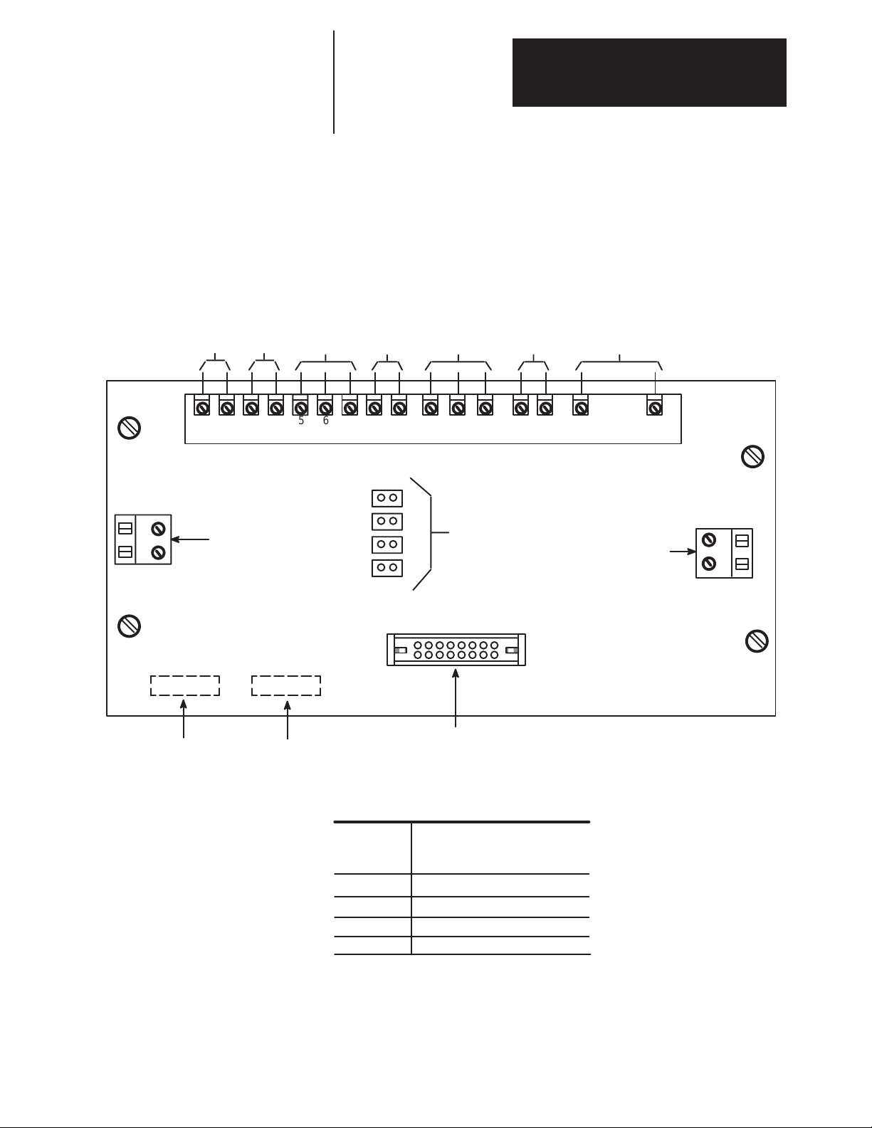
Chapter 3
Hardware Description
40 – 100 HP, 230VAC 75 – 200 HP, 460VAC
Control Boards Feedback Board – Figure 3.5 illustrates the major hardware points on the
board. The primary function of the board is to provide scaling and transfer
of feedback signals coming from power bridge devices being sent to the
Power Stage Interface and eventually to the Main Control Board.
Figure 3.5
Feedback Board (A1) Overview
TB2
From DC
Current
Feedback
Sensor TD1
20 VAC
from
1 PT
1 2314
Connection for AC current
feedback burden resistor
(Factory Installed)
3 Phase Incom-
AC Current
Feedback from
CTs ACT–1 & 2
Field Current
Feedback from
FCT
ing AC Line
voltage Feed-
back
From Heatsink
Thermoswitch
HST
DC Armature Volt-
age Feedback
56789 11 13 15 17 18 20 23
TB1
J1
2
3
4
Jumper Selection
for Field Current
Feedback Scaling
(By User At Start-Up)
Connection for DC current
feedback burden resistor
(Factory Installed)
J2
TB3
MFG Revision No.
Spare Part Kit No.
Connection to Power
Stage Interface
Table 3.A
Feedback Board Jumpers (see Table 8.J)
J1
Jumper
Position
1
2
3
4
40 – 100 HP 240 VDC
75 – 200 HP 500 VDC
Field Current Range
9.1 – 21.2 ADC
4.1 – 9.2 ADC
1.1 – 4.2 ADC
0.65 – 1.2 ADC
3-7
Page 48

Chapter 3
Hardware Description
40 – 100 HP, 230VAC 75 – 200 HP, 460VAC
Figure 3.6
Feedback Board Hardware Location
Feedback
Boards
TB1
TB2
TB3
J1
J2
AB0656A
3-8
Page 49

Chapter 3
Hardware Description
40 – 100 HP, 230VAC 75 – 200 HP, 460VAC
Power Stage Interface (A7) – The primary function of the board is to
provide interface between the Main Control Board, and the Power Bridge
boards such as the Pulse Transformer and Snubber boards, and the Power
Bridge boards such as the Pulse Transformer and Snubber boards and the
Feedback Board. The primary functions performed include:
• Distribution of DC Control power to Main Control Board.
• Provide 3 phase line synchronization signals to Main Control Board.
• Produce all Armature and Field bridge SCR gate signals from
control signals provided from the Main Control Board.
• Contactor and other logic control with interface to Main Control Board
for these functions.
3-9
Page 50

Chapter 3
Hardware Description
40 – 100 HP, 230VAC 75 – 200 HP, 460VAC
Figure 3.7
Power Stage Interface Hardware Location
See Page 6-19
Power Stage
Interface Board
J10
34
16
TP6
TP21
71012
MFG ASSEMBLY #
SPARE PART KIT NO.
J2
1
K2
6
1
1
1 PILOT
PILOT RTN
2
M1–1
3
J1
M1–2
4
120V RTN
5
120 VAC
6
COMMON
1
J11
2
MOTOR
TEMP
3
RESET
4
115V
J12
ECOAST1
5
115V
ECOAST2
6
115V
COMMON
7
FLT 1
8
FLT 2
9
24V
ECOAST+
10
24V
ECOAST–
11
+24V OUT
12
–24V OUT
J9 J8
J3
1
10
MOTOR TEMP
23
1
115V 24V
RESET
1
23
115V 24V
71012
K1
6
1
1
TB1
12A
TP2 TP3
10
J4
11
10
J6
1
1
TP4
C12
+12V
+
TP7
TP9
TP10
TP12
TP13
TP15
TP16
10
TP14
J5
TP8
TP11
TP17
TP18
TP19
TP20
C26
71012
K3
6
J7
1
26
34
TP5
+24V
+
C13
+
AB0661A
3-10
Page 51

Chapter 3
Hardware Description
40 – 100 HP, 230VAC 75 – 200 HP, 460VAC
Main Control Board (A8) – The Main Control Board (Figure 3.8)
performs all control functions of the 1395 drive. Hardware located on the
board is used to support operation of the microprocessor program. The
primary functions performed include:
• Microbus interface.
• Control Firmware
• Analog signal interface
• Develop gate signals sent to the Power Stage Interface
Figure 3.8
Main Control Board Hardware Location
Main Control
Board
J2 J4 J5
Connection to Power Connection to
Stage Interface Board Programming Terminal
TP2 TP5
TP13
123
TP12
Connection
To
Encoder
J1
TP11
TP15
TP23
TP32
TP35
123
1
23
5V 12V
J10
J9
J8
Encoder
Voltage
Selection
TP17 TP8 TP39
TP24
J12
1 2
34
TP42
TP50
VP
TP45
TP46
SP
Port A Port B
TP9 TP6
TP25
TP33
TP34
TP38 TP30
TP43
TP1
UMC8
123
J15
J6J7
Connection To Power
Stage Interface Board
TP21
TP27 TP26
TP31TP29
J13
1 2
34
CP
TP47 TP44
TP20
TP49
TP58
1
J14
2
3
TP54
ISO+12V ISO+5VIGND
TP51
TP52 TP56TP55TP57
+5V –12V+12VDGND AGND
(T o Adapter Board)(T o Adapter Board)
TP28
TP41
TP20
TP53 TP58
TP19
TP10
AB0662A
3-11
Page 52

Chapter 3
Hardware Description
40 – 100 HP, 230VAC 75 – 200 HP, 460VAC
Armature Pulse Transformer and Snubber Board (A2, A3, A4) – The
primary functions of the Armature Pulse Transformer and Snubber Board
(Figure 3.9) include:
• Isolate power bridge circuitry from control circuitry.
• Provide dv/dt protection across SCRs.
There are 3 Armature Pulse Transformer and Snubber Boards. Each board
is associated with a single phase of the incoming AC line. The board is
physically mounted on the armature power bridge busbar, with screw
terminals used to mount the board also used as the connections to the
incoming AC line and DC bus.
Figure 3.9
Armature Pulse Transformer and Snubber Board Hardware Location
Armature Pulse
Board
J1
AB0666A
Field Pulse Transformer and Snubber Board (A5) – The primary
functions of the Field Pulse Transformer and Snubber Board (Figure 3.10)
include:
• Isolate power bridge circuitry from control circuitry
• Provide dv/dt protection across SCRs.
The board is physically mounted on the field power bridge buswork, with
the screw terminals used to mount the board also being used as the
connections to the incoming AC line and DC bus.
3-12
Page 53

Chapter 3
Hardware Description
40 – 100 HP, 230VAC 75 – 200 HP, 460VAC
Figure 3.10
Field Pulse Transformer and Snubber Board Hardware Location
Connection to Power Stage
Interface (SCR Gate Pulses)
MFG
Revision No.
Spare Part
Kit No.
R1
L3 L1
J1
C2
R3
C1
R4
R5
F1
F2
T1 T2
G1 G2
Connection to SCRs
in PM7 of Field Bridge
D10
G1 G2
Connection to SCRs
in PM8 of Field Bridge
T3 T4
Peripheral Devices Unit Power Supply (A6) – The Unit Power Supply 115VAC input comes
from the user external 115VAC power supply. The AC voltage is rectified
and regulated to produce +5VDC and + 12VDC control voltages which are
distributed to the 1395 control boards through the Power Stage Interface.
Figure 3.11 shows the location of components on the Unit Power Supply.
Figure 3.11
Unit Power Supply Hardware Location
C19
C1
C6 C3
R30
Unit Power
Supply Board
J2
C9
C8
C7
C11
C15 C16
F1
AB0663B
C13
J1
3-13
Page 54

Chapter 3
Hardware Description
40 – 100 HP, 230VAC 75 – 200 HP, 460VAC
Power Distribution 115VAC Control Voltage – Figure 3.12 illustrates the distribution of
115VAC control voltage within the Bulletin 1395. Single phase 115VAC
control voltage, provided from an external source by the user enters the
drive at TB2-4 and 5. Fuse F8 provides protection against short circuits on
the 115VAC input to the drive. TB5 (an internal terminal block) distributes
control voltage to components within the 1395.
Figure 3.12
115 VAC Control Voltage Distribution
To
Motor
Field
115 VAC
Control
Power
NOTE: To provide DC Contactor
energization, a jumper or other external circuitry must be connected
between TB2–8 and TB2–9.
F+
F–
Common
TE
PE
SPARE
TB2
1
2
3
4
5
6
7
8
9
10
F8
See
Fig.
3.4
PE
TB5
1
2
3
4
5
6
7
8
9
10
11
12
13
14
15
16
17
18
4 MOV
6 5
A7
Power Stage Interface
115
VAC
H1 X1
1PT
20
VAC
X2H2
To M1 Relay
To PR Relay
F7
See
Fig.
3.13
3-14
1 2
A6
Unit Power Supply
3
2 1
Fan
1
Fan
2
Fan
3
TB7
*
*
*
*
Number of fans varies with Drive size
Page 55

Chapter 3
Hardware Description
40 – 100 HP, 230VAC 75 – 200 HP, 460VAC
DC Control Voltage Distribution – The Unit Power Supply converts
115VAC (supplied as shown in Figure 3.13) to +5VDC and the +/–12VDC
control voltages. In addition to the voltages supplied by the Unit Power
Supply, the Power Stage Interface converts the 20VAC coming from the
control transformer 1 PT to 24VDC which is used for relay logic, including
the ECoast, Pilot Relay, and Fault/No Fault Logic. It also provides the
supply voltage to the SCR Pulse Transformer and Snubber boards to
produce SCR gate signals for the armature and field.
3-15
Page 56

Chapter 3
Hardware Description
40 – 100 HP, 230VAC 75 – 200 HP, 460VAC
Figure 3.13
DC Power Distribution and Control Common
TE
PE
115
VAC
Encoder
Power
Supply
(+12VDC)
A6
UNIT POWER
SUPPLY
6
7
TB2
F7
PT
20
VAC
TB2
TB1 J2
4
FEEDBACK
3
13
14
TE
J1
5
BOARD
Common (ISO)
+12VDC (ISO)
TB4
TX+RX+
PE
10 10
VAC
9 9
TE
J7
TP22 +5VDC
c26
TP4 +12VDC
D GND
c25
A GND
c24
1
2
TP23 Common
TP1 –12VDC
ISO +12V
ISO RTN
J8
+5V
J5
D
A
TP53 ISO GND
TP51 +5VDC
TP52 DGND
TP55 +12VDC
TP57 AGND
TP56 –12VDC
TP54 ISO +12V
J6
Port
B
J7
A7 POWER
STAGE
J2
20
INTERFACE
TP5 +24VDC
17
18
I
17
18
TP41 24V Sense
(approx. 4VDC)
Port
A
B8 MAIN
CONTROL
BOARD
J1
Balun
J4
3-16
To
Programming
Terminal
2
4
6
8
TX– RX–
1
3
5
7
9
Shield
Common (ISO)
+12VDC (ISO)
Balun
Page 57

Chapter 3
Hardware Description
40 – 100 HP, 230VAC 75 – 200 HP, 460VAC
Relay Logic Main Contactor (M1) Control – Figure 3.14 illustrates the hardware
associated with the control of the coil voltage applied to the Main DC
contactor M1. The coil voltage originates at an external 115VAC source.
The source voltage may be interrupted before being input to the drive at
TB2-3 by the use of externally controlled contacts. These external contacts
may include an external master coast stop, PLC controlled contacts,
permissive contacts, etc. Main contactor M1 coil voltage is controlled
within the 1395 through the Power Stage Interface when M1 is energized.
This signal is rectified and optically isolated to produce a 5V logic signal
CVERIFY which is sent to the Main Control Board.
Pilot Relay (PR) Control – K2 and K3 contacts in series with the 115VAC
Coast Stop input to the drive control coil voltage to the Pilot Relay.
ECOAST Stop – The “ECOAST Stop” as defined and illustrated, is a
contingency circuit designed to stop the motor in event of a malfunction in
the solid state interface drive software.
When an ECOAST Stop is initiated, the DC loop contactor is de-energized
and the motor will coast to a stop unless the drive is equipped with
optional dynamic braking circuitry.
The optional dynamic braking circuitry is designed to develop 150% –
200% of rated motor torque for braking when an ECOAST Stop is
initiated. Braking torque decreases with speed. This option is not
recommended for repetitive operation.
Relay K2 on the Power Stage Interface is the ECOAST Stop relay and is
controlled by +24VDC. As shown in Figure 3.14, +24VDC from the
Power Stage Interface is connected to TB3-12 and 11. At this point, an
external (dry) 24 VDC ECOAST stop contact could be used to control the
application of 24VDC to K2 through TB3-9. TB3-12 and 10 should
always be jumpered together to provide a return path for 24VDC. If an
external 24VDC ECOAST Stop contact is not used, then TB3-9 and 11
must be jumpered.
In addition to the 24 VDC ECOAST Stop, there is an 115 VAC ECOAST
Stop circuit which is also provided as standard in the 1395. 115VAC
enters the power stage interface from TB5 and is distributed to TB3-4.
Between TB3-4 and 5, an external (dry) ECOAST Stop contact may be
connected. If an external 115 VAC ECOAST stop circuit is not used,
TB3-4 and 5 must be jumpered. 115VAC is returned to the Power Stage
Interface from TB3-5 and sent to contacts of K2. From here it proceeds to
the contacts of K3 on the Power Stage Interface. The 115VAC ECOAST
Stop Signal is also sent to an isolation circuit which converts the 115VAC
to a +5VDC control Signal ECOAST which is sent to the Main Control
Board.
Main Control Relay – K3 on the Power Stage Interface is the main
control relay which controls turn on voltage to the coil of the pilot relay
PR. K3 is controlled by logic signals from the Main Control board
entering the Power Stage Interface through ribbon connector J9. The two
signals which control K3 are the SYSTRIP and the DCPILOT signals. In
order for K3 to energize PR, there must be no system fault and there must
be a DC pilot relay turn on command. If both these conditions are met, K3
is energized, and PR is in turn energized. The control voltage being
applied to K3 may be monitored on the Power Stage Interface at TP21.
3-17
Page 58

Chapter 3
Hardware Description
40 – 100 HP, 230VAC 75 – 200 HP, 460VAC
PE
Optional
External
Control
Contacts
115
VAC
NOTE: T o provide DC Contactor energization,
a jumper or other external circuitry must be
connected between TB2–8
and TB2–9.
Common
TB2
3
4
5
6
7
8
9
10
F8
TE
If K3 is being commanded to energize, the voltage at TP21 will be 0VDC.
If K3 is to be de-energized, the voltage at TP21 will be +24VDC.
Figure 3.14
Relay Logic
M1
Armature
Bridge
PR
43
16
K3
M1–X
12
12
K
1
3
TB5
10
12
15
3 Phase
AC
A1
A2
To DC
Motor
ECOAST
(Optional)
ECOAST
24VDC
or 115VAC
Source
NOTE: An
explanation
of terminals
1, 2 and 3 is
provided on
pg 6.22.
24VDC
Closed When
Drive is not
Faulted
Motor
Thermostat
NOTE: 24 VDC must
not be used for any
purpose other than
ECOAST
TB3
12
11
10
9
8
7
6
5
4
Reset
3
2
1
From
Main
Control
Board
24 V – OUT
24 V + OUT
24 V ECOAST –
24 V ECOAST +
FLT2
FLT1
115V COMMON OUT
115V ECOAST 2
115V ECOAST 1
Reset In
Motor T emp In
Common In
HST
FAULTED
SYSTRIP
DCPILOT
J1
J1
J10
+ 24 V
K2
J9
SYSTRIP
DCPILOT
115 VAC Common
115 VAC
K2
HY3
HY2
Comm
HY1
AC or DC Overcurrent
5
6
12
11
10
9
8
7
6
5
4
3
2
1
32
16
33
12 34
K3
K1
+ 24 VDC
K1
TP21
+ 24 VDC
K3
A7
Power
Stage
Interface
HY4
ISO
HY5
ISO
CVERIFY
ECOAST
3-18
Page 59

Chapter 3
Hardware Description
40 – 100 HP, 230VAC 75 – 200 HP, 460VAC
Options Programming Terminal Interface – The handheld Programming
Terminal is used to access information in the firmware of the 1395.
Keypads on both the handheld programming terminal and the
door-mounted terminal (shown in Figure 3.15) can be used to perform the
following functions:
• Monitor real time parameter values
• Change parameter values
• Start/Stop the drive (depending on Model of Programming Terminal)
• Sets drive configuration
• Backup parameter values to EEPROM
• Monitor fault information
Interface between the 1395 Main Control Board and the handheld
Programming Terminal is accomplished using a 9 pin type connector
physically mounted on the end of TB3. The cable coming from the D-shell
connector is connected to J4 on the Main Control Board. For a detailed
description of the Programming Terminal, refer to the Programming
Terminal Installation and Operation Manual.
Figure 3.15
Programming Terminal
START
ALT
PRE 4
7
PRE 1
4
D
1
0
LOCAL
PROGRAMMING TERMINAL
JOG
LOCAL
DEC
PRE 5
PRE 2
A
JOG
1
REMOTE
INC
X REF
8
PRE 3
5
E
2
B
.
+/–
STOP
2
9
HOME
MENU
6
BASE
F
DEL
3
C
ENTER
AB0446A
Note: The Programming Terminal can be hand-held or door-mounted when used with the
mounting kit.
3-19
Page 60

Chapter 3
Hardware Description
40 – 100 HP, 230VAC 75 – 200 HP, 460VAC
Adapter Boards – External control devices such as a PLC, discrete
operators devices, etc., are interfaced with the Main Control Board through
one of the two microbus ports, labeled PORT A (J7) and PORT B (J6) on
the Main Control Board. The microbus is a 60 line bus designed
specifically for the transfer of data between microprocessors. The
microbus is used on the Main Control Board to transfer data between
devices on the board. Additionally, hardware on the Main Control Board
allows data transfer between the microprocessor on the Main Control
Board and external devices through the two microbus Ports.
Information coming from external devices must be changed first to the
format required by the microbus before being input to the microbus Port.
The processing of data is accomplished through the use of the following
adapter boards:
Figure 3.16
Construction and Location of Adapter Boards
3-20
Adapter
AB0654A
Boards
Page 61

Chapter 3
Hardware Description
40 – 100 HP, 230VAC 75 – 200 HP, 460VAC
Discrete Adapter Board The Discrete Adapter Board connects directly to the Main Control Board
using Port A of the Microbus interface. All user connections to the board
are made at Terminal Block TB-3 located at the bottom of the 1395 Drive.
Digital Inputs – The Discrete Adapter Board contains four discrete inputs
for either 120VAC signals or 24VDC signals. These optically coupled
inputs provide a means for external control of the 1395 via pushbuttons,
relays, switches, etc.
The inputs are preconfigured for the following signals: STOP, JOG,
START, CLEAR FAULT.
Digital Outputs – Two discrete outputs are provided through control of
two on-board relays. The contact rating is 0.6A at 125VAC and 0.2A at
30VDC. These outputs allow the 1395 to signal various operating states
of the Drive.
The outputs are preconfigured for the following signals: DRIVE
RUNNING, AT ZERO SPEED.
Analog Inputs – Four preprogrammed 12-bit analog to digital inputs.
These inputs allow a +/– 10VDC analog signal to be converted to a +/–
2048 digital signal, thus providing 4.88 millivolts per bit resolution.
Through programming of associated Scale and Offset parameters the
effective range of the converted signal can be extended to +/–32767.
The analog inputs are preconfigured for the following signals:
VELOCITY REFERENCE, TACH VELOCITY, TRIM REFERENCE.
Analog Outputs – Four preprogrammed 11 bit digital to analog outputs.
These outputs allow a +/– 1024 drive signal to be converted to a
+/–10VDC analog analog output, thus giving 9.76 millivolts per bit
resolution. Through programming of associated Scale and Offset
parameters the effective range of the Drive signal can be extended to +/–
32767.
The analog outputs are preconfigured for the following signals:
VELOCITY FEEDBACK, FIELD CURRENT FEEDBACK,
ARMATURE CURRENT FEEDBACK and ARMATURE VOLTAGE
FEEDBACK.
All inputs and outputs have the flexibility to be reconfigured by the user
for other signals. For a detailed description of the discrete adapter refer to
the Discrete Adapter Manual.
Digital Reference Adapter Board The Digital Reference Adapter Board connects directly to the Main
Control Board using Port A of the Microbus interface. This interface
supplies the Adapter Board with all logic voltages and communication
capabilities. The Digital Reference Adapter has the following inputs and
outputs:
Digital Reference Input – One digital reference input which produces a
digital reference command for the Drive. The Adapter Board is set up by
default for the encoder input signal to be single channel dual edge (ie. both
the rising edge and falling edge are used by the counting logic).
Digital Inputs – Ten programmable discrete inputs for 24VDC signals.
They can be connected to any Sink parameter such as the Logic command
word. All ten inputs are LED indicated for high input level visibility.
These optically coupled inputs provide a means for external control of the
1395 via pushbuttons, relays, switches, etc.
3-21
Page 62

Chapter 3
Hardware Description
40 – 100 HP, 230VAC 75 – 200 HP, 460VAC
The inputs are preconfigured for the following signals: RUN
REFERENCE SELECT A,B,C, RAMP DISABLE, JOG2, JOG1,
NORMAL STOP, START, CLOSE CONTACTOR, CLEAR FAULT.
Digital Outputs – Five programmable solid state outputs are provided.
These 24VDC outputs, can be connected to any source parameter such as
the logic status word. All five outputs have LEDs indicating when the
signal is on.
These outputs are preconfigured for the following signals: ZERO SPEED,
DRIVE RUNNING, READY, AT CURRENT LIMIT, AT SET SPEED.
Analog Inputs – Two programmable analog inputs allow a +/– 10 Volt
signal through a 12 bit A to D converter, thus providing 4.88 millivolts per
bit resolution.
The inputs are preconfigured for the following signals: VELOCITY
REFERENCE, TACH VELOCITY.
Analog Outputs – Two programmable analog outputs allow a signal to be
converted to a +/– 10VDC analog output through a 11 bit digital to analog
converter, thus giving 9.76 millivolts per bit resolution. Through
programming of associated Scale and Offset parameters the effective range
of the Drive signal can be extended to +/– 32767. The digital Drive signal
can be any of the 1395 run time parameters.
All user connections to the board are made at terminal block TB3 located
at the bottom of the 1395 Drive.
The outputs are preconfigured for the following signals, VELOCITY
FEEDBACK, ARMATURE CURRENT FEEDBACK.
All inputs and outputs have the flexibility to be reconfigured by the user
for other signals.
For a detailed description of the Digital Reference Adapter, refer to the
Digital Reference Adapter Manual.
Node Adapter Board The Node Adapter Board provides an interface between external devices
and the Main Control Board of the 1395. The board allows the 1395 to be
controlled using an Allen-Bradley PLC Controller from either the PLC3 or
PLC5 family.
The Node Adapter Board is not preconfigured. Refer to the Node Adapter
Manual for hardware and integration information.
Multi-Communication Board The Multi-Communication Adapter Board provides a sophisticated
interface to Allen-Bradley PLC controllers and other equipment capable of
communicating over serial communications links.
The Multi-Communication Adapter is not preconfigured. Refer to the
Multi-Communication Board Software/Hardware Reference Manual, for
hardware and integration information.
3-22
Page 63

Chapter 3
Hardware Description
40 – 100 HP, 230VAC 75 – 200 HP, 460VAC
ControlNet Adapter Board The CNA board provides a sophisticated interface to Allen-Bradley PLC
controllers and other equipment capable of communicating over
ControlNet. This adapter has the following features:
• One ControlNet channel, with a redundant connector to allow for
backup connection in case one cable fails.
• Compatible with all Allen-Bradley PLCs and other products that
support Programmable Controller Communication Commands.
• Compatible with Allen-Bradley 1395 Drives equipped with Version
8.10 or greater software.
3-23
Page 64

Chapter 3
Hardware Description
40 – 100 HP, 230VAC 75 – 200 HP, 460VAC
This Page Intentionally Left Blank
3-24
Page 65

Chapter
Hardware Description
125 – 300 HP; 230VAC
250 – 600 HP; 460VAC
Medium KVA (MKVA)
Introduction Chapter 4 contains both a general description of the major hardware
components of the Series B drive, and background information to support
the procedures detailed in other chapters of this manual. You should use
this chapter in conjunction with the Installation chapter when installing
125 – 300HP, 230VAC and 250 – 600HP, 460VAC Series B Drives.
Terminology A brief description of new terms and concepts covered in Chapter 4 is
presented here:
Adapter Board – Circuit board containing hardware and software required
to interface external devices such as Allen-Bradley PLC or Discrete I/O
devices to the 1395 Series B drive.
Interface – Hardware and associated software required to transfer
information and/or control signals from one device to another.
Microbus – Hardware and associated software designed by Allen-Bradley
for the exchange of digital information at the microprocessor level. The
microbus is used for transfer of information between adapter boards and
the main control board.
Port – Hardware located on the main control board which allows for
connection of one adapter board to the microbus. There are two ports on
the main control board.
Programming Terminal – Device used for programming and monitoring
operation on the 1395 drive. The programming terminal is provided in two
packages: digital handheld terminal and door-mounted terminal.
Important: Refer to Chapter 1, “Publication References” for manuals
describing larger horsepower and current ratings at other line
voltages.
4-1
Page 66

Chapter 4
Hardware Description
125 – 300 HP, 230VAC
250 – 600 HP, 460VAC
Hardware Overview Figure 4.1 provides an overview of the hardware components associated
with the 1395 drive. Hardware can be divided into one of three categories:
• Control Boards
• Control/Power Interface hardware
• Power Hardware
This chapter describes in general all of the major hardware components for
a 125 – 600HP (346 – 980A) drives.
Figure 4.1
Hardware Overview
3 Phase AC
1 Phase AC
Unit
Power
Supply A6
J2
J2
Feedback
Board
A1
L1 L2 L3
F1
Act 2
Act 1
CT
CT
Act 3
F3
F2
Wired By User
See Fig 4.4, 6.11
L1 L3
CT
1 2 3
See Fig 4.2
TB-5
TB-8
J7 J6
Main
Control
Board
A8
J4 J1
Programming
Terminal
DHT/DMT
CONTROL
TB3
J5
J2
J2J7
J8
Power
Stage
Interface
A7
J9
J6 J2
J3
J4
J5
J1
Arm P.T. &
Snubber A4
J1
Arm P.T. &
Snubber A3
J1
Arm P.T. &
Snubber A2
TB-1
J2
Feed
Back
Board
A1
CONTROL/POWER INTERFACE
M1
3 Phase
SCR
Bridge
Armature
A1
Encoder
A2
POWER
FCT
Field
Bridge
F4–
Field
F
3
Fld P.T. &
Snubber
A5
J1
TB7
F1+
F
2
4-2
Page 67

Chapter 4
Hardware Description
125 – 300 HP, 230VAC
250 – 600HP, 460VAC
Armature Bridge Components A general description of the components in the armature bridge (Figures
4.2 and 4.3) and their operation is detailed here:
Incoming Device – Either a line choke or an isolation transformer is
required.
Fuses – Fast acting semiconductor fuses are standard on all ratings.
Synchronization – The three-phase input to the drive is tapped and fused
using fuses F1, F2 and F3 (Fig. 4.2) and enters the Feedback Board at AI
TB1-11, 13, and 15. The feedback board scales down the voltage to a
range from 3.4 to 7.0VAC depending on the three-phase incoming line
voltage. The scaled voltage is sent to the Power Stage Interface where it
is used to develop the synchronizing information to be used by the Main
Control Board.
AC Current Feedback – Current Transformers ACT-1, ACT-2 and
ACT-3 are used to provide current feedback information to the Feedback
Board at AITB1 – 5, 6 and 7. The Feedback Board rectifies the
three-phase feedback and scales the DC voltage before being sent to the
Power Stage Interface. The DC voltage representing current feedback is
passed directly through the Power Stage Interface and sent to the Main
Control Board.
To TB5
see Figure
4.1
L1
L2
L3
Figure 4.2
Armature Bridge Components (Input)
Branch Fuses
F3F2F1
3
2
ACT-1
To Fig. 4.3.
ACT-2
ACT-3
To Feedback Board
1
To Feedback Board
4-3
Page 68

Chapter 4
Hardware Description
125 – 300 HP, 230VAC
PP1 PP2 PP3
250 – 600 HP, 460VAC
Surge Suppression – Surge Suppressor 1 MOV (Fig. 4.2) protects the
armature power bridge from high voltage line spikes and line surges.
SCR Packaging – In 346 – 980A bridges (125 – 600HP) SCRs are
packaged as individual hockey-puck type SCRs. Two SCRs connected in
antiparallel in one of six legs of the bridge is referred to as an SCR cell.
There are 6 SCR cells per bridge for armature regenerative construction.
The non-regenerative version has 6 SCRs only. There are no reversing
SCRs (1R through 6R).
SCR Cell Snubbers – Each SCR cell is protected from rapid rate of
voltage change (dv/dt) using a resistor and capacitor network (referred to
as a Cell Snubber) connected in parallel with the SCR cell.
Figure 4.3
Armature Regenerative Bridge Components (Output)
Snubber
Type 1
S
N
U
B
B
E
R
F12 F11 F10
S
1F 3F 5F
4F 6F 2F
1R 3R 5R
N
U
B
B
E
R
S
N
U
B
B
E
R
S
N
U
B
B
E
R
S
N
U
B
B
E
R
S
N
U
B
B
E
R
S
N
U
B
B
E
R
S
N
U
B
B
E
R
S
N
U
B
B
E
R
S
N
U
2R6R4R
B
B
E
R
FS1
S
N
U
B
FS2
B
E
R
FS3
M1
A1
A1
A2
A2
To
Feedback
Board
4-4
F9 F8 F7
To
Pulse Transformer
Board A2
To
Pulse Transformer
Board A3
To
Pulse Transformer
Board A4
AB0444A
To
Feedback
Board
Page 69

Chapter 4
Hardware Description
125 – 300 HP, 230VAC
250 – 600HP, 460VAC
SCR Cell Fuses – Each SCR cell is protected from high currents by a cell
fuse, located in each leg.
DC Contactor – Output of the armature bridge is connected to the DC
motor through the main DC contactor M1. Coil voltage to M1 is controlled
by contacts from the pilot relay PR (an external 115VAC control input
entering at TB5).
Bridge Output Connections – Bridge output connections labeled A1 and
A2 (Fig. 4.3) correspond to the NEMA standards for connection to the A1
and A2 leads of the DC motor.
Field Bridge Components A general description of the components in the field bridge (Figure 4.4)
and their operation is covered here.
Supply Voltage – The bridge requires two phases fused from an external
source. This is connected to TB8-1 and 3 as detailed in Chap. 6,
Installation.
Field Current Feedback – Current Transformer FCT provides field
current feedback information to the Feedback board at TB1-8 and 9. The
Feedback board rectifies the single phase feedback and scales the DC
voltage using a burden resistor selected by the position of Jumper J1 on the
Feedback Board before being sent to the Power Stage Interface. The DC
voltage representing field current feedback is passed directly through the
Power Stage Interface and sent to the Main Control Board.
Surge Suppression – Surge suppressor 3MOV protects the field power
bridge from line voltage spikes and line surges on the incoming AC line.
2MOV protects the motor field windings from line spikes on the output of
the field bridge.
Line Choke – Line Choke CH1 protects the field power bridge SCRs
from rapid rate of current changes (di/dt).
SCR Modules – Field bridge SCRs are contained in modules made up of
two (2) SCRs per package (PM1 and PM2).
SCR Snubbers – Each forward and reverse armature SCR combination is
protected from rapid rate of voltage changes (dv/dt) using a series
combination of a resistor and capacitor (Snubber) connected in parallel
with the two SCRs. The field SCRs do not have parallel snubbers, but have
them on the input and output of the field bridge. All snubbers are contained
on the Pulse Transformer and Snubber boards, and therefore are not shown
on the bridge schematics.
Bridge Output Connections – The output of the field bridge is connected
to TB7-1 and 3 which in turn is connected to the field leads of the motor.
The terminal labeled F+ on TB2 is connected to the F1 lead of the motor
and terminal F– to the F2 lead.
4-5
Page 70

Chapter 4
Hardware Description
125 – 300 HP, 230VAC
250 – 600 HP, 460VAC
Figure 4.4
Field Bridge Components
User Supplied Fuses
*
L1
*
L3
* Externally
Mounted Devices
TB-8
1
2
3
CH1
FCT (5 turns)
3MOV
L3 G2
PM1
PM2
G1 F2 L1 G1 G2 F1
Field Pulse Transformer
and Snubber Board
A5
2MOV
TB-7
1
2
3
F+
F-
4-6
89
TB-1
Feedback
Board A1
Page 71

Chapter 4
Hardware Description
125 – 300 HP, 230VAC
250 – 600HP, 460VAC
Control Boards Feedback Board – The primary function of the board is to provide
scaling and transfer of feedback signals coming from power bridge devices
being sent to the Power Stage Interface and eventually to the Main Control
Board.
Figure 4.5
Feedback Board (A1) Overview
From DC
Current
Feedback
Sensor TD1
20 VAC
from
1 PT
AC Current
Feedback from
CTs ACT–1, 2 & 3
Field Current
Feedback from
FCT
3 Phase Incom-
ing AC Line
voltage Feed-
back
From Heatsink
Fan Switch
see Fig. 4.3
DC Armature Volt-
age Feedback
TB2
MFG Revision No.
1 2314
Connection for AC current
feedback burden resistor
(Factory Installed)
Assembly Part No.
56789 11 13 15 17 18 20 23
TB1
J1
2
3
Jumper Selection
for Field Current
Feedback Scaling
(By User At Start-Up)
4
J2
Connection to Power
Stage Interface
Table 4.A
Feedback Board Jumpers (see Table 8.J)
J1
Jumper
Position
125 – 300HP 240VDC
250 – 600HP 500VDC
Field Current Range
Note: No resister needed
on MKVA drives.
TB3
1
2
3
4
18.3– 42.4 ADC
8.6 – 18.4 ADC
2.3 – 8.7 ADC
1.0 – 2.4 ADC
4-7
Page 72

Chapter 4
Hardware Description
125 – 300 HP, 230VAC
250 – 600 HP, 460VAC
Power Stage Interface (A7) – The primary function of the Power Stage
Interface board (Fig. 4.6) is to provide interface between the Main Control
Board, and the Power Bridge boards such as the Pulse Transformer and
Snubber boards and the Feedback Board. The primary functions
performed include:
• Distribution of DC Control power to Main Control Board.
• Provide 3 phase line synchronization signals to Main Control Board.
• Produce all Armature and Field Bridge SCR gate signals from control
signals provided from the Main Control Board.
• Contactor and other logic control with interface to Main Control
Board for these functions.
4-8
Page 73

Power Stage
Interface Board
Chapter 4
Hardware Description
125 – 300 HP, 230VAC
250 – 600HP, 460VAC
Figure 4.6
Power Stage Interface Hardware Location
1 PILOT
PILOT RTN
2
M1–1
3
J1
4
5
6
J10
M1–2
115V RTN
115 VAC
COMMON
1
MOTOR
2
TEMP
RESET
3
115V
4
E COAST1
115V
5
E COAST2
115V
6
COMMON
RDY/FLT 1
7
RDY/FLT 2
8
24V
9
E COAST+
24V
10
E COAST–
24V+ OUT
11
24V– OUT
12
MOTOR TEMP
J11
1
115V 24V
RESET
J12
1
115V 24V
1
23
23
71012
TP1
–12V
1
71012
K3
K2
K1
6
1
6
6
1
TP7
TP3
TP6
TP4 TP5
C10
TP2
71012
+12V
J7
26
C1
Spare Part Kit No.
MFG Revision No.
Bar Code
TP8
C30
20
1
TP9
J9
1
J6
20
J4J5
11
J2
1
1610
20
J3
12
TB1
J8
11
AB0657A
4-9
Page 74

Chapter 4
Hardware Description
125 – 300 HP, 230VAC
250 – 600 HP, 460VAC
Main Control Board – Figure 4.7 illustrates the major hardware points on
the board. The board performs all control functions of the Bulletin 1395
drive. Hardware located on the board is used to support operation of the
microprocessor program. The primary functions performed include:
• Microbus interface
• Control firmware
• Analog signal interface
• Develop gate control signals sent to the Power Stage Interface.
Figure 4.7
Main Control Board Hardware Location
Main Control
Board
J2 J4 J5
Connection to Power Connection to
Stage Interface Board Programming Terminal
TP2 TP5
TP13
123
TP12
Connection
To
Encoder
J1
TP11
TP15
TP23
TP32
TP35
123
1
23
5V 12V
J10
J9
J8
Encoder
Voltage
Selection
TP17 TP8 TP39
TP24
J12
1 2
34
TP42
TP50
VP
TP45
TP46
SP
Port A Port B
TP9 TP6
TP25
TP33
TP34
TP38 TP30
TP43
TP1
UMC8
123
J15
J6J7
Connection To Power
Stage Interface Board
TP21
TP27 TP26
TP31TP29
J13
1 2
34
CP
TP47 TP44
TP20
TP49
TP58
1
J14
2
3
TP54
ISO+12V ISO+5VIGND
TP51
TP52 TP56TP55TP57
+5V –12V+12VDGND AGND
(T o Adapter Board)(T o Adapter Board)
TP28
TP19
TP41
TP20
TP53 TP58
TP10
4-10
AB0667A
Page 75

Chapter 4
Hardware Description
125 – 300 HP, 230VAC
250 – 600 HP, 460VAC
Armature Pulse Transformer Boards (A2, A3, A4) – Figure 4.8
illustrates the major hardware points on the board. The primary functions
performed include:
• Isolate power bridge circuitry from control circuitry
• Provides Gate Pulses to the SCRs
There are three Armature Pulse Transformer Boards. Each board is
associated with a single phase of the incoming AC line. The board is
physically mounted on the armature power bridge buswork, with the screw
terminals used to mount the board also used as the connections to the
incoming AC line and the DC bus.
Figure 4.8
Armature Pulse Transformer Board Hardware Location
Armature Pulse
Transformer Board
AB0659A
4-11
Page 76

Chapter 4
Â
Â
Â
Hardware Description
125 – 300 HP, 230VAC
250 – 600 HP, 460VAC
Field Pulse Transformer Boards (A5) – Figure 4.9 illustrates the major
hardware points on the board. The primary functions performed include:
• Isolate power bridge circuitry from control circuitry
• Provide dv/dt protection for SCRs
The board is physically mounted on the field power bridge buswork, with
the screw terminals used to mount the board also being used as the
connections to the incoming AC line and the DC bus.
Figure 4.9
Field Pulse Transformer Board Hardware Location
Field Pulse
Transformer Board
1
MFG Revision No. Spare Parts Kit No.
T1
R2
T3
R8
C2
G11 G12
R3
L3 L1
F1
F2
D10
AK
R4
J1
C3
G21 G22
R1
T2
T4
R9
AB0660A
4-12
Page 77

Chapter 4
Hardware Description
125 – 300 HP, 230VAC
250 – 600 HP, 460VAC
Peripheral Devices Unit Power Supply (A6) – The Unit Power Supply 115VAC input comes
from the user external 115VAC power supply. The AC voltage is rectified
and regulated to produce +5VDC and +/– 12VDC control voltages which
are distributed to the 1395 control boards through the Power Stage
Interface. Figure 4.10 shows the location of the Unit Power Supply.
Figure 4.10
Location of Unit Power Supply
Power Supply
Board
AB0658A
4-13
Page 78

Chapter 4
Hardware Description
125 - 300 HP, 230VAC
250 - 600 HP, 460VAC
Power Distribution 115VAC Control Voltage - Figure 4.11 illustrates the distribution of
115VAC control voltage within the Bulletin 1395. Single phase 115VAC
control voltage, provided from an external source by the user enters the
drive at TB5-4 and 5. Fuse F4 provides protection against short circuits on
the 115VAC input to the drive terminal block TB6 (an internal terminal
block).
Figure 4.11
115VAC Control Voltage Distribution
TB5
L1
1
L2
2
L3
115 VAC
Common
3
4
5
6
7
TE
PE
8
9
10
11
12
See Fig
4.13
See Fig
4.12
NOTE: To provide DC Contactor
energization, a jumper or other external circuitry must be connected
to TB5-8 and 9.
M1
PR
See
Fig.
4.2
PE
F4
1
2
3
4
5
6
7
8
9
A7
Power Stage Interface
A6
Unit Power Supply
TB6
SPMOV
65
J1
12
20
VAC
X2H2
F5
1.5 AMP7 AMP
See
Fig.
4.12
10
11
115
VAC
H1 X1
PT
12
13
14
15
16
17
18
3
4-14
D1
23
14
Fan
1
Fan
2
Fan
3
TB9
To Relay Logic
Page 79

Chapter 4
Hardware Description
125 – 300 HP, 230VAC
250 – 600 HP, 460VAC
DC Control Voltage Distribution – The Unit Power Supply converts
115VAC (supplied as shown in Figure 4.12) to +5VDC and +/– 12VDC
control voltages. In addition to the voltages supplied by the Unit Power
Supply, the Power Stage Interface converts the 20VAC coming from the
control transformer PT to 24VDC which is used for relay logic and
provides the supply voltage to the SCR Pulse Transformer and Snubber
boards to produce SCR gate signals for the armature and field.
Figure 4.12
DC Power Distribution and Control Common
TE
PE
115
VAC
Encoder
Power
Supply
(+12 VDC)
A6
UNIT POWER
SUPPLY
10
11
TB5
F5
PT
20
VAC
TB3
13
14
TE
J1
5
TB1 J2
4
FEEDBACK
BOARD
3
Common (ISO)
+12 VDC (ISO)
TB10
TX +RX +
PE
10 10
9 9
TE
J7
TB1
1
2
J2
C11
C40
C39
A7 POWER
STAGE
INTERFACE
TP4 +5VDC
TP5 +12VDC
TP3 Common
TP6 +24VDC
TP1 –12VDC
ISO +12VDC
ISO RTN
+5V
J8
J5
TP41 24V Sense
(approx. 4VDC)
A8 MAIN
CONTROL
BOARD
J1
J4
TP51 +5VDC
TP52 DGND
TP55 +12VDC
TP57 AGND
TP56 –12VDC
TP54 ISO 12V
TP53 ISO GND
Balun
Balun
J6
Port
B
J7
Port
A
To
Prog
Term
1
2
3
4
5
6
7
8
9
TX – RX –
Shield
Common (ISO)
+12 VDC (ISO)
Balun
Balun
4-15
Page 80

Chapter 4
Hardware Description
125 – 300 HP, 230VAC
250 – 600 HP, 460VAC
Relay Logic Main Contactor (M1) Control – Figure 4.13 illustrates the hardware
associated with the control of the coil voltage applied to the Main DC
contactor M1. The coil voltage originates at an external 115VAC source.
The source voltage may be interrupted before being input to the Drive at
TB5-6 by the use of externally controlled contacts. These external contacts
may include an external master coast stop contact, PLC controlled
contacts, permissive contacts, etc. These contacts are illustrated
as“external control contacts”. Main contactor M1 coil voltage is
controlled within the 1395 through the pilot relay (PR) contacts.
Auxilliary contacts on M1 send 115VAC to the Power Stage Interface
when M1 is energized. This signal is rectified and optically isolated to
produce a 5V logic signal CVERIFY which is sent to the Main Control
Board.
Pilot Relay (PR) Control – K2 and K3 contacts in series with the
115VAC Coast Stop input to the drive control coil voltage to the Pilot
Relay.
ECOAST Stop – The “ECOAST STOP” as defined and illustrated, is a
contingency circuit designed to stop the motor in the event of a
malfunction in the solid state interface drive software.
4-16
When an ECOAST Stop is initiated, the DC loop contactor is de-energized
and the motor will coast to a stop.
Relay K2 on the Power Stage Interface is the ECOAST stop relay and is
controlled by +24VDC. As shown in Figure 4.13, +24VDC from the
Power Stage Interface is connected to TB3-12 and 11. At this point, an
external 24VDC ECOAST stop contact could be used to control the
application of 24VDC to K2 through TB3-9. TB3-12 and 10 should
always be jumpered together to provide a return path for 24VDC. If an
external 24 VDC ECOAST stop contact is not used, then TB3-9 and 11
must be jumpered.
In addition to the 24VDC ECOAST stop, there is a 115VAC ECOAST stop
circuit which is provided as standard in the 1395. 115VAC enters the
Power Stage Interface from TB6 and is distributed to TB3-4. Between
TB3-4 and 5, an external ECOAST stop contact may be connected. If an
external 115VAC ECOAST stop circuit is not used, TB3-4 and 5 must be
jumpered. 115VAC is returned to the Power Stage Interface from TB3-5
and sent to the contacts K2. From here it proceeds to the contacts of K3 on
the Power Stage Interface. The 115VAC ECOAST stop signal is also sent
to an isolation circuit which converts the 115VAC to a +5VDC control
signal ECOAST which is sent to the Main Control Board.
Main Control Relay – K3 on the Power Stage Interface is the main
control relay which controls turn on voltage to the coil of the pilot relay
PR. K3 is controlled by logic signals from the Main Control board
entering the Power Stage Interface through ribbon connector J9. The two
signals which control K3 are the SYSTRIP and the DCPILOT signals. In
order for K3 to cause PR to be energized, there must be no system fault
and there must be a DC pilot relay turn on command. If both these
conditions are met, K3 is energized, and PR is in turn energized. The
control voltage being applied to K3 may be monitored on the Power Stage
Interface at TP2. If K3 is being commanded to energize, the voltage at TP2
will be 0VDC. If K3 is to be de-energized, the voltage at TP2 will be
+24VDC.
Page 81

Figure 4.13
Relay Logic
Chapter 4
Hardware Description
125 – 300 HP, 230VAC
250 – 600 HP, 460VAC
NOTE: A jumper
must be used if
external cotacts
aren’t used at
TB5 6&7.
NOTE: To provide DC Contactor energization,
a jumper or other external circuitry must be
connected to
TB5–8 and 9
24VDC
ECOAST
(Optional)
Closed When
Drive is not
Faulted
ECOAST
24VDC
or 115VAC
Source
Motor
Thermostat
Common
NOTE: An
explanation
of terminals
1, 2 and 3 is
provided on
pg 6.22.
115 VAC
Com
External
Contacts
NOTE: 24 VDC must
not be used for any
purpose other than
ECOAST
Reset
TB5
F4
4
5
6
7
8
9
10
11
12
PE
TB3
24 V – OUT
12
24 V + OUT
11
24 V ECOAST –
10
24 V ECOAST +
9
RDY/FLT2
8
RDY/FLT1
7
115V COMMON OUT
6
115V ECOAST 2
5
115V ECOAST 1
4
Reset In
3
Motor T emp In
2
Common In
1
Hot
TE
See Fig
4.12
115 VAC
FAULTED
SYSTRIP
DCPILOT
TB6
10
1
11
2
12
3
4
13
514
15
6
5
3
12
11
10
9
8
7
6
5
4
3
2
1
Com
J1
J10
+ 24 V
12 7
K2
J9
SYSTRIP
DCPILOT
+
D1
–
115 VAC Common
115 VAC
HY3
HY2
Hot
6
K2
712
3 Phase
AC
J1
12 7
K3
1
K1
Armature
Bridge
PR
43
12
K3
12 34
+ 24 VDC
61
K1
M1
A1
To DC
Motor
A2
M1–X
12
2
–+
+ 24 VDC
TP2
61
K3
1
K
HY4
CVERIFY
ISO
To Main
Board
HY5
ECOAST
ISO
To Main
Board
A7
Power
Stage
Interface
4-17
Page 82

Chapter 4
Hardware Description
125 – 300 HP, 230VAC
250 – 600 HP, 460VAC
Options Programming Terminal Interface – Both versions of the handheld
Programming Terminal are used to access information in the firmware of
the 1395. Keypads on both the handheld programming terminal and the
door-mounted terminal (shown in Figure 4.14) can be used to perform the
following functions:
• Monitor real time parameter values
• Change parameter values
• Start/Stop the drive (depending on Model of Programming Terminal)
• Sets drive configuration
• Backup parameter values to EEPROM
• Monitor fault information
Interface between the 1395 Main Control Board and the handheld
Programming Terminal is accomplished using a 9 pin type connector
physically mounted on the end of TB3. The cable coming from the D shell
connector is connected to J4 on the Main Control Board. For a detailed
description of the Programming Terminal, refer to the Programming
Terminal Installation and Operation Manual.
Figure 4.14
Programming Terminal
START
ALT
PRE 4
PRE 1
JOG
1
LOCAL
DEC
PRE 58X REF
7
PRE 25PRE 3
4
PROGRAMMING TERMINAL
JOG
2
REMOTE
INC
9
6
LOCAL
STOP
HOME
MENU
4-18
D
1
A
0
E
2
B
.
+/–
BASE
F
DEL
3
C
ENTER
AB0446A
Note: The Programming Terminal can be hand-held or door-mounted when used with the
mounting kit.
Page 83

Chapter 4
Hardware Description
125 – 300 HP, 230VAC
250 – 600 HP, 460VAC
Adapter Boards – External control devices such as a PLC, discrete
operators devices, etc., are interfaced with the Main Control Board through
one of the two Microbus ports, labeled PORT A (J7) and PORT B (J6) on
the Main Control Board. The Microbus is a 60 line bus designed
specifically for the transfer of data between microprocessors. The
Microbus is used on the Main Control Board to transfer data between
devices on the board. Additionally, hardware on the Main Control Board
allows data transfer between the microprocessor on the Main Control
Board and external devices through the two Microbus Ports.
Information coming from external devices must be changed first to the
format required by the Microbus before being input to the Microbus Port.
The processing of data is accomplished through the use of the following
adapter boards:
Figure 4.15
Construction and Location of Adapter Boards
Adapter
Boards
AB0655A
4-19
Page 84

Chapter 4
Hardware Description
125 – 300 HP, 230VAC
250 – 600 HP, 460VAC
Discrete Adapter Board The Discrete Adapter Board connects directly to the Main Control Board
using Port A of the Microbus interface. All user connections to the board
are made at Terminal Block TB-3 located at the bottom of the 1395 Drive
(Fig. 4.15).
Digital Inputs – The Discrete Adapter Board contains four discrete inputs
for either 120VAC signals or 24VDC signals. These optically coupled
inputs provide a means for external control of the 1395 via pushbuttons,
relays, switches, etc.
The inputs are preconfigured for the following signals: STOP, JOG,
START, CLEAR FAULTS.
Digital Outputs – Two discrete outputs are provided through control of
two on-board relays. The contact rating is 0.6A at 125VAC and 0.2A at
30VDC. These outputs allow the 1395 to signal various operating states of
the Drive. The outputs are preconfigured for the following signals:
DRIVE RUNNING, AT ZERO SPEED
Analog Inputs – Four preprogrammed 11-bit analog to digital inputs.
These inputs allow a +/– 10VDC analog signal to be converted to a +/–
2048 digital signal, thus providing 4.88 millivolts per bit resolution.
Through programming of associated Scale and Offset parameters the
effective range of the converted signal can be extended to +/–32767. The
analog inputs are preconfigured for the following signals: VELOCITY
REFERENCE, TACH VELOCITY, TRIM REFERENCE.
Analog Outputs – Four preprogrammed 11 bit digital to analog outputs.
These outputs allow a +/– 1024 drive signal to be converted to a +/–
10VDC analog analog output, thus giving 9.76 millivolts per bit resolution.
Through programming of associated Scale and Offset parameters the
effective range of the Drive signal can be extended to +/– 32767.
The analog outputs are preconfigured for the following signals:
VELOCITY FEEDBACK, FIELD CURRENT FEEDBACK,
ARMATURE CURRENT FEEDBACK and ARMATURE VOLTAGE
FEEDBACK.
All inputs and outputs have the flexibility to allow reconfiguration by the
user for other signals.
For a more detailed description of the Discrete Adapter refer to the
Discrete Adapter Manual.
Digital Reference Adapter Board The Digital Reference Adapter Board connects directly to the Main
Control Board using Port A of the Microbus interface. This interface
supplies the Adapter Board with all logic voltages and communication
capabilities. The Digital Reference Adapter has the following inputs and
outputs:
Digital Reference Input – One digital reference input which produces a
digital reference command for the Drive. The Adapter Board is set up by
default for the encoder input signal to be single channel dual edge (ie. both
the rising edge and falling edge are used by the counting logic).
Digital Inputs – Ten programmable discrete inputs for 24VDC signals.
They can be connected to any Sink parameter such as the Logic command
word. All ten inputs are LED indicated for high input level visibility.
These optically coupled inputs provide a means for external control of the
1395 via pushbuttons, relays, switches, etc.
4-20
Page 85

Chapter 4
Hardware Description
125 – 300 HP, 230VAC
250 – 600 HP, 460VAC
The inputs are preconfigured for the following signals: RUN
REFERENCE SELECT A,B,C, RAMP DISABLE, JOG 2, JOG1,
NORMAL STOP, START, CLOSE CONTACTOR, CLEAR FAULT.
Digital Outputs – Five programmable solid state outputs are provided.
These 24VDC outputs, can be connected to any source parameter such as
the logic status word. All five outputs are LED indicated for high input
level visibility.
These outputs are preconfigured for the following signals: ZERO SPEED,
DRIVE RUNNING, READY, AT CURRENT LIMIT, AT SET SPEED.
Analog Inputs – Two programmable analog inputs allow a +/– 10 volt
signal through a 12 bit A to D converter, thus providing 4.88 millivolts per
bit resolution.
The inputs are preconfigured for the following signals: VELOCITY
REFERENCE, TACH VELOCITY.
Analog Outputs – Two programmable analog outputs allow a +/– 1024
Drive signal to be converted to a +/– 10VDC analog output through a 12
bit digital to analog converter, thus giving 9.76 millivolts per bit resolution.
Through programming of associated Scale and Offset parameters the
effective range of the Drive signal can be extended to +/– 32767. The
digital Drive signal can be any of the 1395 run-time parameters.
The outputs are preconfigured for the following signals, VELOCITY
FEEDBACK, ARMATURE CURRENT FEEDBACK.
All user connections to the board are made at Terminal Block TB3 located
at the bottom of the 1395 Drive.
All inputs and outputs have the flexibility of being reconfigured by the
user for other signals.
For a more detailed description of the Digital Reference Adapter, refer to
the Digital Reference Adapter Manual.
Node Adapter Board The Node Adapter Board provides an interface between external devices
and the Main Control Board of the Bulletin 1395. The board allows the
1395 to be controlled using an Allen-Bradley PLC Controller from either
the PLC3
or PLC5
family.
For a more detailed description of the Node Adapter, refer to the Node
Adapter Manual.
Multi-Communication Board The Multi-Communication Adapter Board provides a sophisticated
interface to Allen-Bradley PLC controllers and other equipment capable of
communicating over serial communications links.
The Multi-Communication Adapter is not preconfigured. Refer to the
Multi-Communication Board Software/Hardware Reference Manual, for
hardware and integration information.
4-21
Page 86

Chapter 4
Hardware Description
125 – 300 HP, 230VAC
250 – 600 HP, 460VAC
ControlNet Adapter Board The CNA board provides a sophisticated interface to Allen-Bradley PLC
controllers and other equipment capable of communicating over
ControlNet. This adapter has the following features:
• One ControlNet channel, with a redundant connector to allow for
backup connection in case one cable fails.
• Compatible with all Allen-Bradley PLCs and other products that
support Programmable Controller Communication Commands.
• Compatible with Allen-Bradley 1395 Drives equipped with Version
8.10 or greater software.
4-22
Page 87

Chapter
Functional Description
Introduction Chapter 5 contains a general description of the functionality of the 1395
drive. This description is intended to provide sufficient background
information to support other procedures in this manual and to enable the
reader to:
• Configure the parameters of the drive.
• Interface the drive with peripheral devices such as an Allen-Bradley PLC,
discrete operators I/O and the Programming Terminal.
This chapter is not intended to be an all encompassing technical description
of the 1395 drive.
Terminology Following is a brief description of new terms and concepts covered in
Chapter 5.
Configuration The process of linking Sink to Source parameters.
Fast Parameter Fast parameters are all parameters whose values are
updated every 4msec, and are used for the
real time data input and output of the drive. Fast
parameters are backed up in volatile memory only.
Interface Hardware and associated software required to
transfer information and/or control signals from one
device to another.
Microbus Hardware and associated software designed by
Allen-Bradley for the exchange of digital
information at the microprocessor level. The
Microbus is used for the transfer of information
between Adapter Boards and the Main Control
Board.
Port Hardware located on the Main Control Board which
allows for connection of one Adapter Board to the
Microbus. There are two ports on the Main Control
Board.
Parameter Memory location used to store drive data. Each
parameter is given a number called the parameter
number. The parameter value may be specified in
decimal or hexadecimal. When specified in
hexadecimal, the word “Hex” will appear after the
parameter value.
5-1
Page 88

Chapter 5
Functional Description
Parameter Table Table of parameter entries for all Configuration and
Source Fast parameter used as a source of data.
Sink Fast parameter used to receive data input.
Functional Overview General
Figure 5.1 provides an overview of the major blocks associated with the
control functions of the Bulletin 1395. All control functions in the 1395 are
performed through the use of parameters which can be changed with a
Programming Terminal.
Feedback information is derived from hardware devices as shown on the
right side of Figure 5.1. Analog signals are converted to digital signals for
use by the drive. Control signals may be provided to the drive from up to
two optional Adapter Boards.
Setup parameters used in the drive.
All setup and operation information used by the drive is stored in a system
parameter table. Every parameter including Setup and Configuration
parameters (Sources and Sinks) has an entry in the parameter table. For
example, parameter 154 is named the “Vel Ref Whole” parameter and
contains a number representing the velocity reference. The velocity
reference can originate from an external control device such as a
potentiometer connected to the Discrete Adapter Board or a signal coming
from a PLC. Refer to Chapter 7 for parameter descriptions.
5-2
Page 89

Figure 5.1
Functional Overview
Chapter 5
Functional Description
Programming
Adapter
Terminal
Communication Control
External
T orque
Reference
Port A
Adapter
Board
Interface with
Parameter Table
Torque
Reference
Select
Velocity
Control
Port B
Board
Armature
Reference
T orque Reference
Current
Drive Logic
Control
Armature Current
Control
Armature Current Feedback
Three-Phase AC Voltage Feedback
Voltage
Reference
DC Current Feedback
Armature Voltage Feedback
3-Ph. Line Sync
Armature Sync
& Firing Logic
Three-Phase Line
L1 L2 L3
Three-Phase
Disconnect
To Field
Bridge
Three-Phase
Armature
Bridge
External
Speed
Reference
Preset 1
Preset 2
Preset 3
Preset 4
Preset 5
Jog 1
Jog 2
Ramp
Control
Speed
Reference
Select
MOP
Control
Velocity
Feedback
Select
Field Flux
Control
LEGEND
Hardware
Software
Hardware/Software Interface
Encoder Velocity
Feedback
Optional DC Tach
Feedback
Phase
Angle
Field Sync &
Firing Control
Field Current Feedback
Line Sync
Arm.
A
B
DC
T o Discrete Board
Single-Phase
Field Bridge
Single-Phase AC
Supply from Three-
Phase Drive Input
Optional
Velocity
Feedback
Device
5-3
Page 90

Chapter 5
Functional Description
Communication Control
The Communication Control block controls all of the data transfer. The
Programming Terminal communicates with the drive through an RS-422
serial communication link. Internal communication in the drive is
accomplished using a Microbus which is a specialized microprocessor bus
designed by Allen-Bradley. In addition to internal communication, transfer
of data between the drive and up to two Adapter Boards is provided
through the Microbus. The hardware used for this interface is known as a
Microbus Port. Two ports (labeled A and B) are available. Adapter
Boards provide an interface between external control hardware such as
discrete devices, PLC’s, etc.
Drive Logic Control
This block controls the operating state of the drive in response to the logic
command input. Selection of various reference parameters (i.e. speed
reference) and control modes (i.e. droop) are performed in the drive Logic
Control. In addition to controlling the state of the drive, the drive Logic
Control monitors the present operating condition of the drive and provides
this information as available feedback to external control devices. The
drive Logic Control also monitors fault sensing.
Speed Reference Selection
There are five preset speeds stored in parameters in the drive.
Additionally, an External Speed Reference and one of two Jog inputs may
be selected as the velocity reference input to the drive. The Speed
Reference Select block uses information provided from the drive Logic
Control to determine which of the available references will be used as the
input to the Velocity Control. The selected reference is sent to a ramp
before being sent as the velocity reference input to the Velocity Control.
Velocity Feedback Select
The drive has been designed for normal operation using one of three
possible means of velocity feedback. Hardware for interfacing the drive to
a digital encoder is provided as standard in the drive. Armature voltage is
constantly monitored by the drive and can be used for velocity feedback. If
a DC tachometer is used for speed feedback, the drive must be equipped
with a Discrete Adapter Board connected to Port A of the Microbus.
IMPORTANT: An external voltage divider for the DC Tach will be
needed to obtain the correct voltage for the Discrete Adapter Board analog
input circuit. Refer to Chapter 6 for details.
Feedback in the form of an analog signal from the DC tach is sent to the
Discrete Board, converted to a digital signal and scaled for input to the
Velocity Feedback Select block. The Velocity Feedback Select block uses
information stored in a drive setup parameter to determine which of the
feedback signals is to be sent to the Velocity Control.
5-4
Page 91

Chapter 5
Functional Description
Velocity Control
The Velocity Control compares the velocity reference to the velocity
feedback to determine the velocity error.
Torque Reference Select
The 1395 can operate as either a speed regulated or a torque regulated
drive, and therefore has the capability to accept either a velocity reference
or a torque reference input. In addition, the Torque Reference Select block
allows the drive to operate as a torque regulated drive and still have the
velocity control operational. In this case, the drive can receive both a
velocity reference and a torque reference at the same time. The Torque
Reference Select block selects from either the output of the Velocity
Control, or the External Torque Reference or both, depending on the mode
of operation being commanded from the Drive Logic Control block. The
reference which is selected is scaled based on the motor ratings to a current
reference.
Armature Current Control
Armature current reference is compared to the Armature Current Feedback
derived from the output of the current transformers (CT’s). The Armature
Current Control block produces a Voltage Reference which is applied to the
Armature Sync and Firing Logic. In addition, the Armature Current
Control monitors the Three-Phase AC Voltage and Armature Voltage
Feedback.
Armature Sync and Firing Logic
The Voltage Reference output from the Armature Current Control is
converted to a phase angle reference and then a time reference. The signal
is then synchronized to the incoming three-phase line to produce the gate
firing pulse for the SCRs located in the Armature Bridge. The Logic also
provides synchronizing information to the Field Sync and Firing Logic.
Field Flux Control
The Field Current Control uses the Field Flux Reference from the Velocity
Control to develop a field current reference. This reference is then
compared to the Field Current Feedback derived from the current
transformers in the incoming AC line to the Field Bridge. The error
between the field current reference and feedback produces a field Phase
Angle which is sent to the Field Sync and Firing Logic.
5-5
Page 92

Chapter 5
Functional Description
Field Sync and Firing Logic
The Phase Angle output from the Field Current Control is converted to a
time reference which is synchronized to the Line Sync signal from the
Armature Sync and Firing Logic to produce the gate firing pulses for the
SCRs.
Configuration Figure 5.2 shows an overview of the parameters associated with
configuration of the drive. The 1395 has been designed to accept control
input through the use of Adapter Boards. A portion of the drive control has
been designed to act as a black box from the point of view of external
devices. In order to perform the control functions required by the specific
application, it is necessary to configure various control and reference
information such as logic commands, speed reference and torque
reference. Additionally, for the external control equipment to monitor the
operating conditions in the drive (logic status, actual speed, actual armature
current etc.), configuration provides a way for this information to be
transferred to the external devices.
Sink Parameters
Several parameters associated with the control logic have been set aside
specifically for the task of receiving input information from external
control devices. These parameters are called “Sinks.” Figure 5.2
illustrates some of the Sink parameters used for input to the control logic.
Refer to Table 5.A. for a listing of Sink parameters.
5-6
Page 93

Figure 5.2
Source and Sink Parameters (Partial)
Chapter 5
Functional Description
Programming Terminal
Interface
Port A
Interface
Programming
Terminal
Sources
200 - 204
Programming
Terminal
Sinks
250 - 254
Port A
Sources
400
409
Port A
Sinks
450
459
1395 Drive
Control Logic
Sinks
150
Logic Cmd 1
151
Logic Cmd 2
152
Logic Cmd 3
154
Velocity Ref. Whole
156
Tach Velocity
157
Torque Reference
Sources
100
Logic Status
101
Drive Fault
106
Velocity Feedback
112
Arm. Current Fdbk.
Port B
Interface
Port B
Sources
300
309
Port B
Sinks
350
359
113
114
115
116
117
118
119
5-7
Page 94

Chapter 5
Functional Description
Table 5.A
Control Sink Parameters
Number
150
151
152
153
154
156
157
159
160
161
162
163
164
165
166
Name
Logic Cmd 1
Logic Cmd 2
Logic Cmd 3
Vel Ref Fraction
Vel Ref Whole
Tach Velocity
Torque Reference
Flux Feed Fwd
CEMF Reference
Process Trim Ref
Proc Trim Fdbk
Vel Indirect 1
Vel Indirect 2
Vel Indirect 3
Vel Indirect 4
Function
First 16 Bit Logic Command Word
Second 16 Bit Logic Command Word
Third 16 Bit Logic Command Word (Program Terminal)
External Velocity Reference Fractional Part
External Velocity Reference Whole Part
Tachometer feedback signal coming from analog tach or other
external velocity feedback device
Torue Reference input. Used when drive operates as a torque
regulator.
External flux reference used as a feed forward term in field
regulator.
Counter EMF Reference. Used when drive is operated as a
torque regulator
Process Trim Reference Input
Process Trim feedback derived from external sensing device
Indirect parameter, linked to slow Parameter 600
Indirect parameter, linked to slow Parameter 601
Indirect parameter, linked to slow Parameter 602
Indirect parameter, linked to slow Parameter 603
The function of each Sink parameter has been pre-defined and cannot be
changed. For example, Parameter 151 (Logic Cmd 2) has been specifically
set aside for the function of drive logic control. Because each Sink
parameter has been defined for a specific use, each Sink parameter will
have a specific data type and units of measure.
For example, Parameter 151 (Logic Cmd 2) is a 16 bit word where each bit
has been defined for a specific function such as Start, Stop, Close
Contactor, etc. A description of each parameter is provided in Chapter 7.
The specific external control devices which can be interfaced with the
drive are defined by the type of Adapter Boards connected to Microbus
Ports A and B on the Main Control Board. For example, the drive could be
controlled by discrete hardware such as push buttons and pots. In this case,
a Discrete Adapter Board would be required to interface the discrete
control hardware to Port A. If interface with a PLC is desired, a Node
Adapter Board is required in Port B.
Each Adapter Board also has Sink parameters associated with it as shown
in Figure 5.2.
5-8
Page 95

Chapter 5
Functional Description
Source Parameters
Information input to a Sink parameter must originate from a Source
parameter which transmits the information through the Microbus Ports. As
shown in Figure 5.2, there are 10 Source parameters associated with each
of the ports. The specific hardware devices associated with the Source
parameters are determined by the Adapter Board which has been physically
connected to the port. For example, if a Discrete Adapter Board has been
connected to Port A, then Parameter 400 is defined as a 16 bit word, where
4 of the bits can be controlled directly by the 4 digital inputs to the board.
If a Node Adapter Board has been connected to Port B, then Parameter 300
is defined as a 16 bit word, where all 16 bits are directly controlled by the
program in the PLC. Refer to Chapter 6 for details on pre-configuration of
the 1395 drive.
The control logic also provides Source parameters which may be used to
send information to the Sink parameters associated with the Microbus
Ports. Some of the Source parameters associated with the control logic
have been shown in Figure 5.2. Table 5.B lists the Source parameters
associated with the control logic.
There are additional sets of configuration links that cross the fast and slow
parameter interface. These are called “indirect parameters”. The velocity
processor has Parameters 600 through 603 that link to fast Parameters 163
through 166. The system processor has slow Parameters 840 through 844
that link to fast Parameters 10 through 14.
Indirect Parameters – These parameters allow data to be transferred
between fast and slow parameters. There are a total of nine indirect
parameters, four for the Velocity Processor and five for the System
Processor.
The Velocity Processor parameters transfer a fast data value to a slow
parameter value. When a configuration link is made with a Velocity
Processor indirect parameter (Parameters 163 – 166), the real time data
value is transferred to the parameter number specified in the corresponding
Velocity select parameter (Parameters 600 to 603). Therefore, the real time
data value is copied to a velocity processor setup parameter.
The System Processor indirect parameters transfer a slow data value to a
fast source parameter. When a configuration link is made with a system
Processor indirect parameter (Parameters 10 to 14), the data value
programmed in the corresponding System select parameter (Parameter 840
to 844) is transferred to the indirect parameter. Therefore, a constant real
time value is established which can be modified by entering a new value in
the system select parameters.
5-9
Page 96

Chapter 5
Functional Description
Table 5.B
Control Logic Source Parameters
Number
100
101
102
103
104
105
106
107
108
109
110
111
112
113
114
115
116
117
118
119
Name
Logic Status
Drive Fault
Pre Ramp Vel Ref
Ramp Vel Ref
Final Vel Ref
Arm Voltage Fdbk
Velocity Fdbk
Position Fdbk
Vel Feed Fwd
Position Error
Torque Command
Arm Current Ref
Arm Current Fdbk
Arm Cur PI Out
Arm Cur Fire Ang
Flux Command
AC Line Voltage
Fld Current Ref
Fld Current Fdbk
Proc Trim Output
Function
16 bit word used to indicate the present operating condition of
the drive.
16 bit word used to indicate fault conditions in the drive.
Velocity reference output from the Velocity Reference Control
Velocity reference output from the Ramp Control.
Velocity Reference input to the Velocity PI Control which is the
sum of the output from the Ramp Control, Process Trim and
Droop functions.
Actual armature voltage.
Final velocity feedback used as input to the Velocity PI
Control.
Final position feedback used as input to the position control
portion of the Velocity PI Control
Error term used in proportional path of the velocity PI regulator
Error between position reference and position feedback
(P107)
Internal Torque Reference
Torque command scaled by flux command.
Actual armature current.
Output of the Armature Current PI Control
P113 converted to an angle reference modified by
discontinuous current adaptation when operating in
discontinuous current range.
Output of the field flux control.
Actual three-phase input line voltage.
Flux command scaled by the Field Flux Linearization Table.
Actual field current.
Output of velocity trim control.
5-10
Linking Source to Sink Parameters
In order for information from a Source parameter to be input to a Sink
parameter, a link must be made between the two desired parameters. For
example, to send the information from Parameter 400 (first Source
parameter associated with Port A) to Parameter 151 (pre-defined as Logic
Cmd 2, input), then Parameter 151 must be linked to Parameter 400.
Linking of Parameter 151 to 400 is shown in Figure 5.3.
Linking of parameters is accomplished using the drive Setup Mode on the
Programming Terminal. The drive will allow a total of 20 links to be
made. There are two fixed links that cannot be altered or reconfigured,
thereby allowing a maximum of 18 user configurable links. Linking of
Sources to Sinks is referred to as “Configuring” the drive. For a complete
description of how to use the Programming Terminal to configure the
drive, refer to the Programming Terminal Instruction Manual. It should be
Page 97

Chapter 5
Functional Description
noted that the 1395 drive is shipped from the factory pre-configured. The
user has the capability of reconfiguring the drive as required.
Figure 5.3
Linking Sources to Sinks
Programming Terminal
Interface
Port A
Interface
Programming
Terminal
Sources
200 - 249
Programming
Terminal
Sinks
250 - 299
Port A
Sources
400
401
Port A
Sinks
450
451
1395 Drive
Control Logic
Sinks
150
Logic Cmd 1
151
Logic Cmd 2
152
Logic Cmd 3
154
Velocity Ref. Whole
156
Tach Velocity
157
Torque Ref
Sources
100
Logic Status
101
Drive Fault
106
Velocity Feedback
112
Arm. Current Fdbk.
Port B
Interface
Port B
Sources
300
349
Port B
Sinks
350
399
Trend Buffer
1–49 Source
50–99 Links
5-11
Page 98

Chapter 5
Functional Description
The specific function and data requirements for each source parameter
associated with the ports is defined by the Sink parameter from the control
firmware to which it is linked. For example, in Figure 5.3, Parameter 400
is linked to Parameter 151 (Logic Cmd 2). Because Logic Cmd 2 has been
pre-defined as a 16 bit control word, parameter 400 must be handled by the
Adapter Board, and in turn by the external control devices, as the 16 bit
control word Logic Cmd 2 (i.e. parameter 400 takes on the meaning of
Logic Cmd 2).
The same condition is true for Sink parameters associated with the
Microbus Ports. For this reason, Sink and Source parameters associated
with the ports have no meaning until they are linked to Source and Sink
parameters from the control logic. Information may be flowing between the
hardware connected to the Adapter Boards and the Source and Sink
parameters associated with the corresponding Microbus Port, but until the
Sink and Source parameters associated with the port are linked to control
logic Source and Sink parameters, no transfer of data to the drive control
will occur.
Example Configuration Using Discrete Adapter Board – Figure 5.4
shows a Discrete Adapter Board connected to Port A. The Discrete
Adapter Board provides for up to four 24VDC/115VAC digital inputs, four
analog inputs, two digital output contacts, and four analog outputs. Wiring
to the actual discrete devices is provided through terminal TB3 in the drive
package. Logic in the drive allows for scaling of input information for
each analog input, before it is sent to the respective Source parameters.
There are four Source parameters associated with the analog inputs,
(Parameters 401 – 404 for PortA and Parameters 301 – 304 for Port B).
The four digital inputs to the drive are all sent to bits in a single 16 bit
word which is to be used as a logic command input word. Parameters 400
for Port A and 300 for Port B are used for this purpose. Each of the four
digital inputs to the Discrete Board can be configured to go to any of the 16
bits in the logic word for each port. The hardware of the Discrete Board,
therefore, defines the possible usage for each of the Source and Sink
parameters associated with the specific Port to which the Board has been
connected.
In Figure 5.4 the Discrete Board has been connected to Port A, so only the
Port A Source and Sink Parameters are defined by the hardware of the
Discrete Board. Parameter 400, by definition of the Discrete Board must
be linked in the Drive to to one of the logic command Sink parameters. In
this example, Parameter 400 is linked to Parameter 151, Logic Command
2, so the four digital inputs to the Discrete Board will directly control four
of the bits in Logic Command 2. Parameter 401, which is associated with
the first analog input to the Discrete board is linked to Parameter 154,
which means the analog signal entering the Discrete Board is defined as the
External Velocity Reference input to the Control Logic.
5-12
Page 99

Chapter 5
Functional Description
Figure 5.4
Discrete Adapter Board Configuration Example
DC Tach
+V 0V
Discrete
Adapter
A/D
A/D
D/A
D/A
Programming Terminal
Interface
Port A
Interface
Bit
Sel
16 Bits
Scale Offset
Scale Offset
Bit
Sel
16 Bits
ScaleOffset
ScaleOffset
Programming
Terminal
Sources
200 - 249
Programming
Terminal
Sinks
250 - 299
Port A
Sources
400
401
402
Port A
Sinks
450
451
452
1395 Drive
Control Logic
Sinks
150
Logic Cmd 1
151
Logic Cmd 2
152
Logic Cmd 3
154
Velocity Ref. Whole
156
Tach Velocity
157
Torque Ref
Sources
100
Logic Status
101
Drive Fault
106
Velocity Feedback
112
Arm. Current Fdbk.
Port B
Interface
Port B
Sources
300
349
Port B
Sinks
350
399
5-13
Page 100

Chapter 5
Functional Description
In this example, the speed feedback is being provided by a DC tachometer.
The standard drive control is set up to use a digital Encoder for speed
feedback, therefore, the standard hardware of the drive does not have an
input for DC tach feedback. In this case, the DC tach feedback must be
provided through the Discrete Board as an analog input as shown in Figure
5.4. The speed feedback derived from the tach appears at Parameter 402,
and is linked to Parameter 156 which is the Tach Velocity input to the
Control Logic and is used for external speed feedback.
In a similar manner, information from the Control Logic is linked to Sink
parameters associated with Port A to provide digital and analog outputs
from the Discrete Board as shown in Figure 5.4. Data flow between the
Control Logic and other Adapter Boards may be traced in the same
manner. For detailed information pertaining to the hardware and
parameters associated with each Adapter Board, refer to the Installation
and Maintenance Manual for that specific board.
Auto-tuning The 1395 drive contains software that enables the drive to test and tune its
current loop, velocity loop and field flux loop upon command. These
features can be operated from the available program terminals or through a
PLC program. Several of these tests require that the motor be capable of
running at base speed. The choices available are detailed below.
– Current Loop Test. This feature checks the drive armature bridge for
shorts or open circuits, verifies that armature voltage sensing is operating
and measures the motor armature circuit.
– Current Loop Tune. This feature uses the information determined by
the current loop test to tune the drive current loop.
– Velocity Loop Motor Test This feature calculates the motor inertia by
running the motor under a controlled set of circumstances. The motor
must be disconnected from the load to run this test.
– Velocity Loop System Test. This feature calculates the system inertia by
running the motor under a controlled set of circumstances. The motor
must be connected to the load to run this test.
– Velocity Loop Tune. This feature programs the drive velocity loop gains
based on the information determined by the velocity loop motor and
system tests.
– Field Flux Tune. This feature calibrates the drive field flux table to the
actual motor field. The motor must be capable of running to complete
this procedure. Due to the reduction of available torque, it may be
necessary to disconnect the load to run this procedure.
5-14
 Loading...