

Page 1
Bulletin
1391
Servo
AC
(Series
A.
Controller
ts)
ana
1
a;aaaa*-
dm
W&l
lnstruction
Manual
|i
'
i'V:
:
mm
m
mi
mm
1
1
p
i
iiiai
4
a
’
V
\
%
sa
m
\
:
%
I
%
1
p
:a-a/;
|
aSlflii
.a
illilSl
a'-aa-aa-
IBliiHIMliiiil
:Va:
aa-;
Wi:.
my.
W:0:
%
a-
1
MMI
'
fig
-
%
'ÿ
my
mi
aa.
\-yy
wwM
%
MSI
siiii
.........
........
mm
iiiiiiiil
iMiM
a
a
I
;-a
%
1
1
agaga
"
;
.
.
5
'.a.'
g
a-"
a
&
a
a
mm
M
a'
i
§
.a.
M
§§g
«B8r
,
,
>
,'a.
a':'a
MM
II
aa-
\
aaa
:
m
1
,
a
—
Page 2
Important
User
Information
Because
differences
equipment,
must
of
or
application
The
text
associated
cannot
illustrative
No
use
of
satisfy
the
equipment.
liable
for
illustrations
this
of
assume
patent
information,
of
the
variety
between
user
the
themselves
In
indirect
of
this
equipment.
shown
manual.
with
any
responsibilityorliability
uses
and
liability
is
uses
of
this
solid-state
of
and
those
as
to
no
event
or
consequential
this
in
Because
particular
applications.
assumed
circuits
or
this
for
equipment
responsible
the
acceptability
Allen-Bradley
will
manual
many
of
the
installation,
by
Allen-Bradley
equipment
equipment
and
for
applying
of
damages
are
resulting
intended
variables
the
Allen-Bradley
for
actual
Company
describedinthis
and
becauseofthe
electromechanical
this
equipment
each
application
Company
solely
and
use
be
responsible
the
from
to
illustrate
requirements
Company
upon
based
with
respect
text.
and
use
the
use
or
the
to
Reproduction
written
The
each
to
procedures.
permission
information
chapter
so.
Do
do
WARNING:
injured
A
CAUTION:
economic
A
These
reader-alerts
The
•
•
•
•
probability
The
probability
The
consequences
How
to
avoid
of
the
in
in
sequence
not
proceed
if
these
content
the
Allen-Bradley
of
this
manual
and
the
to
tells
procedures
tells
readers
can
you
severity
severity
of
improper
occur
loss
help
and
and
consequences.
of
this
is
organized
perform
next
readers
are
not
if
identify:
hazards.
of
damage.
of
use.
manual,
chapter
about
where
procedures
in
Company
in
procedures
until
hazards
followed
machinery
or
whole
prohibited.
is
numbered
when
you
have
and
properly.
may
are
not
in
part,
chapters.
are
you
completed
where
prople
damaged
be
followed
without
Read
instructed
all
may
or
properly.
be
Hazard
alert
labels
are
on
the
product.
Page 3
Table
Contents
of
Table
Contents
of
Page
1
Chapter/
Section
1
1.0
1.1
1.2
1.3
1.4
1.5
1.6
2
2.0
2.1
2.2
2.3
2.4
3
3.0
3.1
3.2
3.3
3.4
Manual
General
Controller
Series
Standard
Objectives
Precautions
Description
A,
and
B
Features
Controllers
D
Options/Modifications
Controller
Chapter
Controller
Environmental
Controller
Transformer
Chapter
Receiving
Unpacking
Inspection
Storing
Layout
Objectives
Specifications
Specifications
Power
Dissipation
Power
Objectives
Dissipation
.
.
Receiving,
Title
Introduction
Specifications
Unpacking
and
Page
1-1
1-1
1-2
1-3
1-4
1-4
1-5
2-1
2-1
2-2
2-2
2-2
Inspection
3-1
3-1
3-1
3-1
3-1
4
4.0
4.1
4.2
4.3
4.4
4.5
4.6
4.7
4.8
4.9
4.10
4.11
4.12
4.13
5
5.0
5.1
5.2
5.3
Chapter
Objectives
General
300V
DC
Power
PWM
Operation
Shunt
Controller/System
Starting
Regulator
Logic
Power
Logic
Control
Isolated
Integral
Line/DB
Power
Power-Up/Down
Chapter
Inputs/Outputs
Supply
Current
Circuit
Contactor
Driver
Stopping
and
Objectives
Board
Board
Potentiometer
Switch
and
Jumper
Supply
Bus
Operation
Monitor
Fault
Sensing
Breaker
Sequence
Adjustments
Settings
Description
and
Inputs,
Detection
Outputs
Operation
of
Adjustments
and
4-1
4-1
4-1
4-1
4-2
4-2
4-2
4-3
4-4
4-4
4-4
4-4
4-5
4-5
5-1
5-1
5-4
5-5
Page 4
Page
Table
II
Contents
of
Chapter/
Section
6
6.0
6.1
6.2
6.3
7
7.0
7.1
8
8.0
8.1
8.2
8.3
9
9.0
9.1
9.2
9.3
Chapter
Mounting
Wiring
Wiring
Chapter
Start-Up
Chapter
Objectives
Recommendations
Objectives
Procedure
Objectives
Introduction
Bulletin
Motor
Chapter
Bulletin
Shunt
Shunt
1326AB
Maintenance
Objectives
1391
Regulator
Regulator
Operation
Motor
Options
Transformers
Operation
Installation
with
the
Transformers
Title
Installation
Start-Up
Bulletin
Shunt
and
1326
Regulators
Servomotor
AC
Page
6-1
6-1
6-2
6-3
7-1
7-1
8-1
8-1
8-3
8-5
9-1
9-1
9-4
9-6
10
10.0
10.1
10.2
Appendix
A
B
c
Chapter
System
Test
Objectives
Troubleshooting
Point
Controller
Interconnect
Cable
Information
Descriptions
Dimensions
Drawings
...
—
.
Troubleshooting
10-1
10-1
10-4
A-1
B-1
C-1
Page 5
Chapter
1
Introduction
Manual
1.0
Objectives
This
manual
troubleshooting
arranged
troubleshooting
operation,
understood
Caution,
the
IMPORTANT:
Only.
Refer
information
Important
This
single
to
limitationsofthis
installation,
points:
is
It
to
the
manual
controller
help
the
This
equipment
component
While
when
same
meant
is
order
in
the
material
before
Warning
not
intended
Bulletin
the
on
Information
has
user
setup
controller
potential
the
used
considerations
solid-state
Manufacturers
design
standards
requirements.
In
the
compliance
regulations
control
electrical
of
and
actual
factory
with
which'
guide
to
Bulletin
of
a
from
a
and
maintenance.
presented
proceeding.
and
This
manual
for
1391B-ES
Bulletin
prepared
been
application.
understand
equipment
and
maintenance
has
been
in
hazards
system
a
in
to
are
be
equipment
engineering
and
control
codes
for
environment,
applicable
beyond
are
the
1391
general
Particular
Important
is
use
with
Instruction
1391B-ES
about
It
the
including
designed
integrated
an
associated
environment,
given
equipment
specific
machine
interface,
AC
description
To
must
statements
standard
for
the
Servo
ensure
thoroughly
be
attention
Bulletin
Manual
installation,
Controller.
the
of
successful
contained
Bulletin
1391B-ES
Controller.
this
Manual
primarily
standard
is
a
individual
procedures.
to
to
characteristicsofother
and
the
groups
safety
the
scope
the
support
to
document
operating
hazards
meet
the
controller
with
the
it
cumulative
responsible
refer
must
guidelines
user
is
operator
and
purpose
and
associated
Note
requirements
must
responsible
setup
The
controller
installation
read
and
must
be
1391
directed
within.
Controllers
Controller.
further
for
product
this
is
that
characteristics
with
following
the
system.
controller
be
noted
peripheral
impact
to
and
on
specification
for
applicable
interface
to
safety
codes
this
of
and
contents
to
and
to
in
a
intended
and
of
a
remain
that
the
special
safety.
industry
ensure
or
document.
are
or
General
1.1
Precautions
addition
In
following
and
understood.
A
A
to
precautions
the
statements
WARNING:
Servo
Controller
implement
maintenance
personal
in
CAUTION:
result
can
Wiring
life.
motor,
ent
incorrect
temperatures
which
Only
installation,
the
of
the
injury
An
component
in
application
or
throughout
listed
general
are
personnel
and
associated
controller.
and/or
incorrectly
inadequate
or
may
to
familiar
start-up
equipment
applied
damage
errors,
resultinmalfunction
this
the
controller
machinery
and
Failure
damage.
or
reduction
or
a
such
supply,
AC
manual,
with
the
should
subsequent
comply
to
installed
undersizing
as,
or
of
the
must
be
Bulletin
plan
may
controller
product
in
excessive
the
controller.
read
1391
or
result
the
ambi¬
Page 6
1-2
Page
Introduction
General
1.1
Precautions
(Continued)
A
CAUTION:
Discharge)
precautions
repairing
or
ESD
familiar
Allen-Bradley
sensitive
control
with
Electrostatic
Handbook.
controller
This
required
are
assembly.
this
procedures
control
static
publication
Damage
parts
are
or
any
may
assemblies.
and
installing,
when
Component
not
followed.
procedures,
8000-4.5.2,
other
contain
damage
reference
Guarding
applicable
ESD
Static
testing,
you
If
ESD
(Electrostatic
control
servicing
may
result
not
are
Against
Protection
if
Controller
1.2
Description
IMPORTANT:
Controllers,
Servo
Transformer.
The
user
accordance
codes
The
Bulletin
dedicated,
require
number
a
equipment
The
Bulletin
positioning
various
components
All
front
enclosure
included
is
The
Bulletin
voltage
AC
which
speed
responsible
is
with
may
that
single
minimum
a
of
industries.
system
machine
cover.
and
to
with
proportional
is
and/or
features
The
servomotor.
RMS
with
all
Transformer,
complete
the
order
In
the
of
Use
the
apply.
Pulse
1391
axis,
1391
is
to
members
are
controller
ventilated
circulate
1391
converts
controlled
current
The
controller
package
Bulletin
system.
servo
to
user
any
other
for
National
Width
servo
AC
amount
required
generally
control
mounted
with
air
user
a
to
(torque)
sizes
1326
maintain
provide
must
transformer
providing
Electrical
Modulated
controller.Ithas
space
panel
of
by
the
with
used
position
the
on
automated
an
open
in
an
is
intended
filtered
power
the
over
three-phase,
a
supplied
of
Bulletin
a
available
is
being
Servomotor
AC
amplitude
identical.
phase,
listing
UL
power
motor
overload
Code
Servo
while
machine
computer
a
and
framed
to
be
and/or
heat
50/60
analog
1326
ratings
in
on
from
voids
the
(NEC),
Controller
been
containing,
tool
and
linear
machine.
package
panel
mounted
cooled
sink.
Hz
frequency.
and
command,
permanent
of
Bulletin
A
and
Bulletin
Allen-Bradley
Isolation
1391
a
listing.
UL
protection
and
packaged
any
is
as
in
other
a
automated
aided,
or
rotary
closed
motion
withaslide-on
an
in
An
to
regulates
22.5
1391
1326
internal
variable
a
The
magnet
and
Cables
air.
input,
15,
1391
local
to
standard,
loop
of
fan
output
the
AC
45A
Page 7
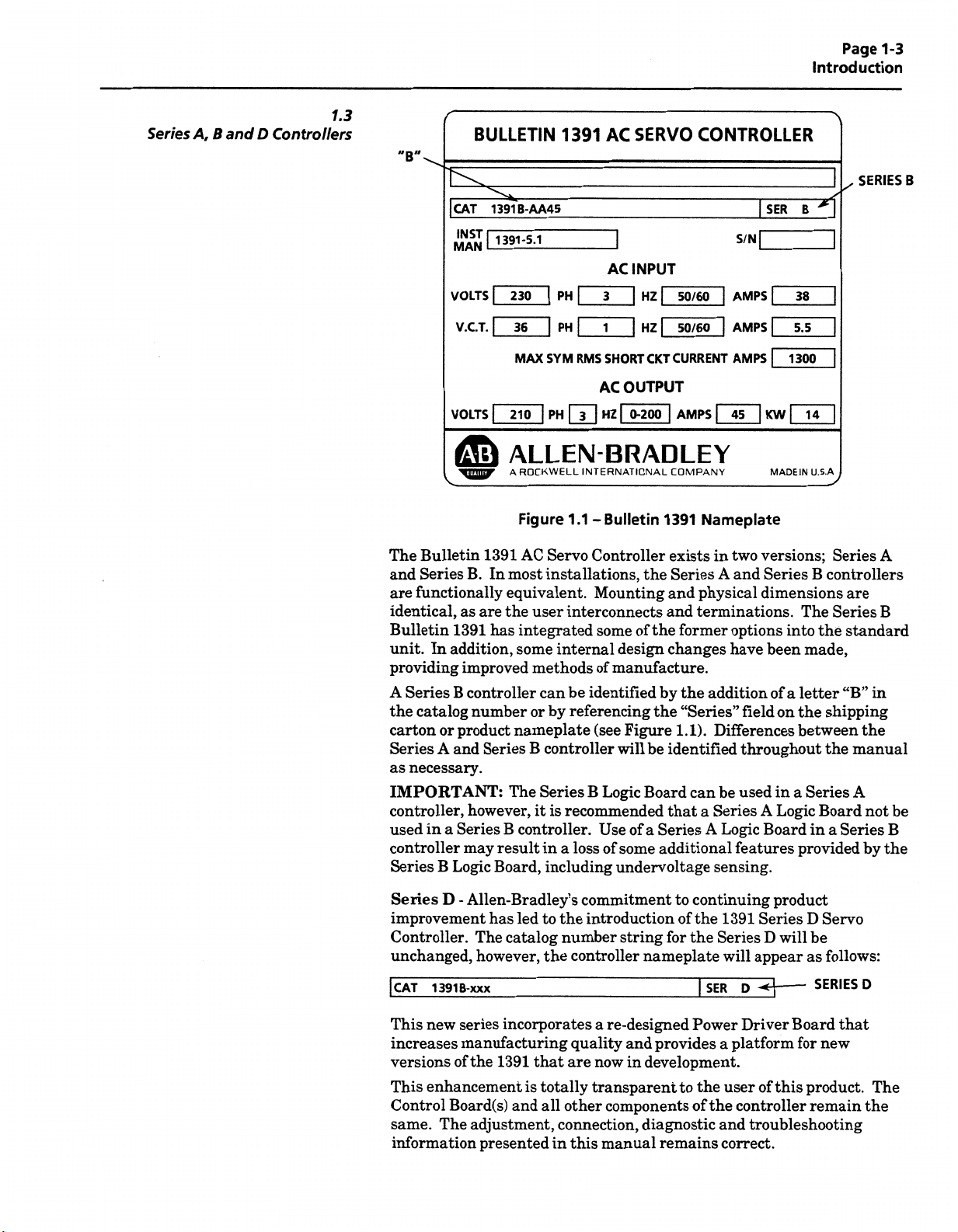
Series
A,
Page
1-3
Introduction
1.3
and
B
D
Controllers
"B"
BULLETIN
1391
AC
SERVO
CONTROLLER
SERIES
B
CAT
l
INST
MAN
VOLTS
V.C.T.
VOLTS
OWII.y
The
Bulletin
Series
and
functionally
are
identical,
Bulletin
unit.
In
providing
A
Series
catalog
the
carton
Series
necessary.
as
B.
as
1391
addition,
improved
B
controller
number
product
or
and
A
1391
are
Series
IMPORTANT:
controller,
used
controller
Series
in
a
B
Series
Logic
however,
may
1391B-AA45
1391-5.1
1
230
l
|
36
MAX
210
ALLEN
A
ROCKWELL
Figure
AC
In
most
equivalent.
the
user
integrated
has
some
methods
can
or
nameplate
B
Series
The
it
B
controller.
result
Board,
AC
|
PH
l
l
SYM
PH
Servo
3
PH
1
l
RMS
SHORT
AC
HZ
[T]
BRADLEY
INTERNATIONAL
1.1-
Bulletin
Controller
installations,
Mounting
interconnects
some
internal
of
manufacture.
be
identified
by
referencing
(see
controller
Logic
B
is
recommended
Use
in
loss
of
a
including
INPUT
|
[
50/60
HZ
|
|
HZ
CKT
50/60
CURRENT
OUTPUT
AMPS
0-200
I
l
COMPANY
1
391
exists
the
Series
and
and
the
of
former
design
will
the
Figure
be
Board
changes
by
the
“Series”
1.1).
identified
can
that
Series
of
a
additional
some
undervoltage
SER
1
S/N[
|
|
[
Nameplate
in
A
physical
terminations.
addition
Differences
be
Series
a
Logic
A
sensing.
|
AMPS
|
AMPS
|
AMPS
j
KW
45
MADE
two
versions;
Series
and
dimensions
options
have
been
of
fieldonthe
throughout
used
A
Board
features
38
5.5
1300
]
IN
The
into
letter
a
between
a
in
Logic
provided
*
B
1
|
|
|
|
14
U.S.A
Series
B
controllers
Series
the
made,
shipping
the
Series
Board
Series
a
in
A
are
B
standard
“B”
in
the
manual
A
not
by
the
be
B
Series
improvement
D
-
Controller.
unchanged,
|
CAT
13918-xxx
This
new
increases
versions
This
Control
same.
of
enhancement
Board(s)
The
information
Allen-Bradley’s
has
led
to
catalog
The
however,
series
manufacturing
the
1391
adjustment,
presented
the
incorporates
that
totally
is
and
all
commitment
the
introductionofthe
number
string
controller
re-designed
a
quality
are
now
and
in
transparent
components
other
connection,
this
in
manual
continuing
to
the
|
Series
SER
for
nameplate
Power
provides
a
development.
to
the
of
the
diagnostic
remains
and
product
Series
1391
will
D
will
appear
D
-
Driver
platform
of
user
this
controller
troubleshooting
correct.
Servo
D
be
as
SERIES
Board
new
for
product.
remain
follows:
D
that
The
the
Page 8

1-4
Page
Introduction
Standard
1.4
Features
The
Bulletin
typical
a
in
Input
A
and
protected
power
inserts
•
•
contactor
integral
An
•
the
event
standard
A
•
regulator.
A
shunt
•
motor
Velocity
•
between
Logic
•
troubleshooting
Three
•
have
UL
•
Transformers),
during
Board
controller
identical
listed
contains
1391
automated
against
line/DB
shunt
a
de-energized.
is
circuit
of
short
a
300V
regulator
regenerative
components
loop
to
0.03
1.0
that
and
mounting
per
UL
CSA
a
machine
transient
contactor
regulator
breaker
circuit
power
DC
resistor
in.-lbs.-sec2.
can
ratings
508
quickly
be
diagnostics.
that
dimensions.
(file
general
standard
number
which
which
conditioninthe
bus
to
braking.
compensate
to
#E59272
of
system.
servo
voltage.
opens
resistor
dissipate
are
file
across
will
open
supply
the
removed
the
in
volume1,section
-
LR32334-23,C22.2
the
that
for
and
same
features
AC
the
three
all
power
includes
energy
system
a
easily
physical
to
line
DC
bus
AC
circuitry.
an
generated
interchanged
and
required
the
controller
whenever
line
integral
inertia
package
10,
IEC
leads
by
the
range
and
Drives
146.
the
in
shunt
for
and
Options/
1.5
Modifications
The
Bulletin
following
The
Contactor
-
N.O.
Two
power
to
the
brake
control
Current
-
When
the
system,
torque
External
-
On
the
power.
regenerative
shunt
for
the
integral
The
amplifier
and
15
DC
bus
regulator
user
jumper
45A
Some
IMPORTANT:
standard
1391
are
Auxiliary
contacts
terminal
circuit
Torque
or
velocity
the
controller
Shunt
22.5A
voltage
applications
energy
mounting
on
TB5
fusing
controller
equipment
most
at
the
These
an
being
configured
be
the
of
Resistor
regulator
such
rated
controllers.
5A
from
externally
units.
45A
functions
user's
on
indicator
Operation
closed
plug
as
386
at
external
an
the
shunt
contains
selectable
Switch
mounted
are
block.
or
as
Amplifier
loop
is
can
by
use
Regulator
controllersaninternal
shunt
dissipate.
to
resistor
22.
on
using
and
accessible
has
an
external
An
on
needed
option:
the
main
contacts
that
part
as
operate
to
jumpers.
power
dissipate
can
overhauling
an
For
these
watts
Thisisselectable
resistor.
outside
regulator
An
of
mounted
additional
servo
a
in
power
contactor
be used
can
contactor
the
position
the
of
as
resistor
125
load
applications,
continuous
The
and
15
22.
resistor
resistor
unit
in
a
current
that
watts
have
can
shunt
5A
and
included
is
not
is
has
an
system.
wired
and
motor
a
closed.
control
or
part
is
continuous
excessive
external
supplied
be
removing
by
has
controllers.
fuse.
as
required.
of
Page 9
Options/
1.5
Modifications
(Continued)
-
Tach
A
voltage
1.5V
Output
equal
DC/1000
to
RPM
2.5V
on
DC/1000
units
set
RPM
for
5000
is
available
RPM
TB2.
at
operation.
Page
1-5
Introduction
Controller
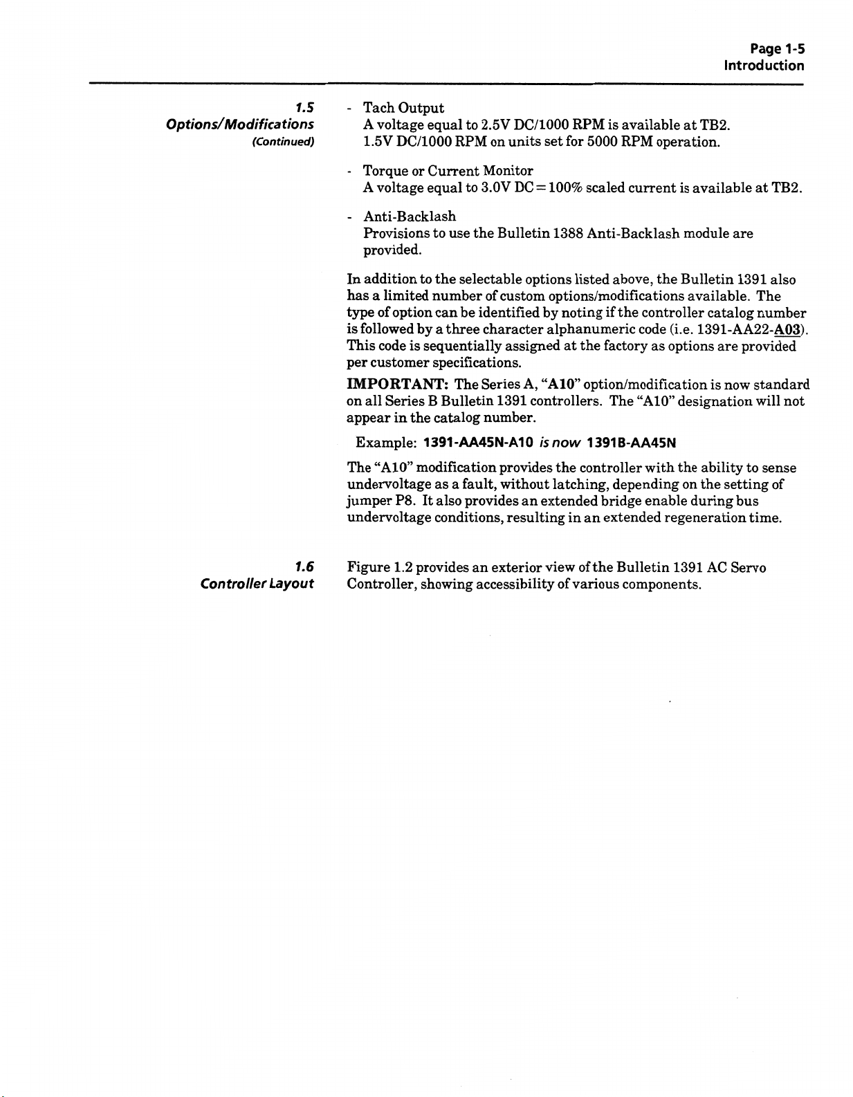
1.6
Layout
Torque
-
A
voltage
Anti-Backlash
-
Current
or
equal
Provisions
provided.
In
additiontothe
hasalimited
type
is
This
per
option
of
followed
code
customer
by
sequentially
is
IMPORTANT:
on
Series
all
appear
Example:
The
“A10”
undervoltage
jumper
undervoltage
Figure
Controller,
B
in
the
1391-AA45N-A10
modification
P8.
It
provides
1.2
showing
Monitor
3.0V
to
to
the
use
Bulletin
selectable
custom
identified
be
three
The
fault,
a
provides
an
accessibility
of
character
assigned
Series
1391
number.
provides
without
resulting
exterior
number
can
a
specifications.
Bulletin
catalog
as
also
conditions,
100%
DC
options
A,
=
by
“A10”
scaled
Anti-Backlash
1388
listed
options/modifications
noting
alphanumeric
at
the
option/modification
controllers.
now
is
an
extended
the
latching,
in
of
view
various
of
controller
an
1391B-AA45N
the
current
above,
the
if
controller
code
factory
The
“A10”
with
depending
bridge
enable
extended
Bulletin
components.
available
is
module
the
Bulletin
available.
1391-AA22-A03)
(i.e.
options
as
designation
the
on
during
regeneration
1391
catalog
are
now
is
ability
the
setting
AC
at
are
1391
The
number
provided
standard
will
to
bus
time.
Servo
TB2.
also
.
not
sense
of
Page 10
Page
1-6
Introduction
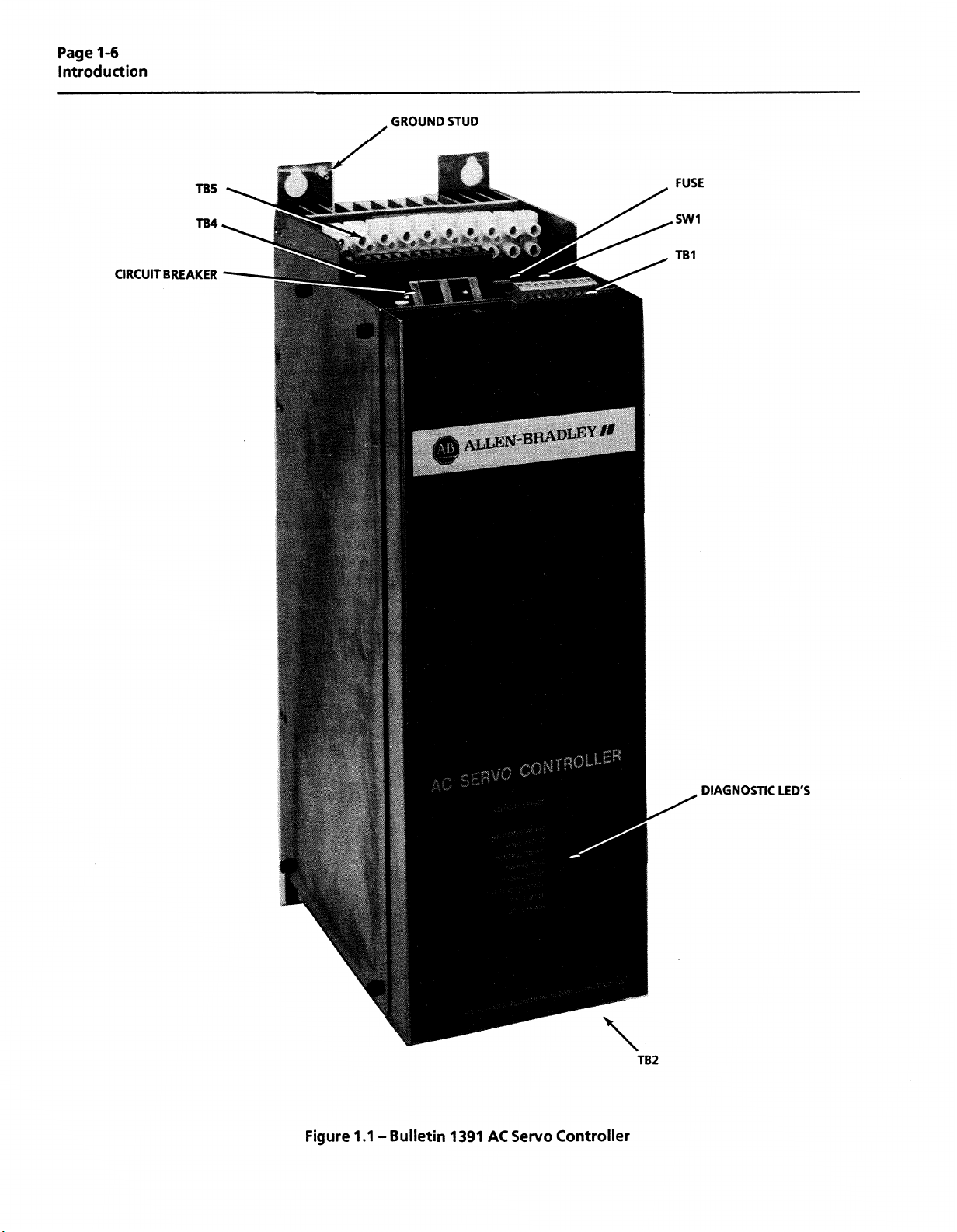
CIRCUIT
TB5
TB4
BREAKER
m
fit
mi
,1111
m
m
§j|g|gg
§§11
\<
WM
1|
GROUND
‘
i
STUD
tL
ALLEN-BRApLEY#f
;
h:
j
FUSE
SW1
TB1
|
a
SI
WBm
umm
mSS§Wm
I
v,
:
m
*
:
f'.
50
I
III
DIAGNOSTIC
LED'S
Figure
1.1-
Bulletin
1
391
AC
Servo
\
TB2
Controller
Page 11
Chapter
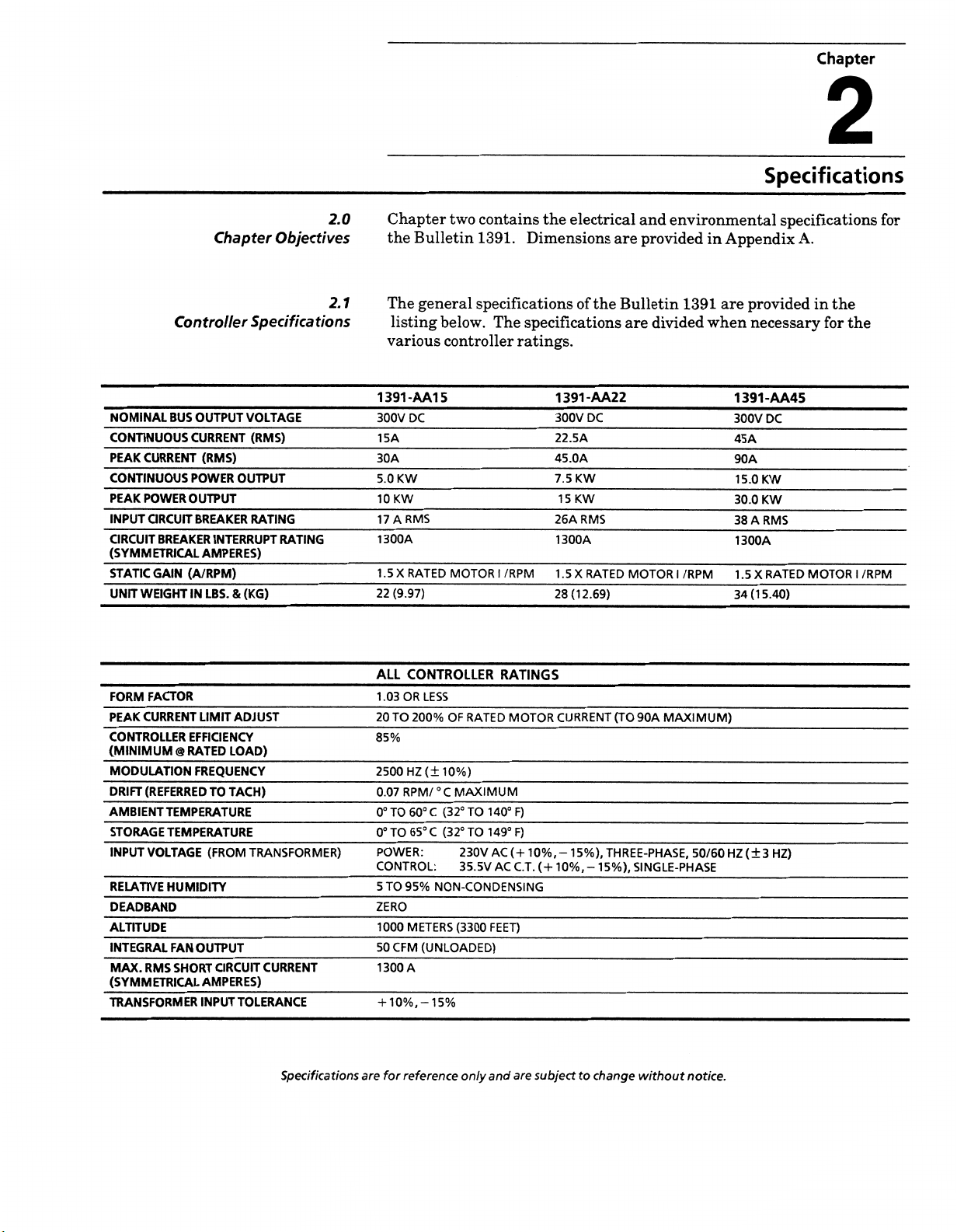
2
Specifications
Controller
NOMINAL
CONTINUOUS
PEAK
CONTINUOUS
PEAK
INPUT
CIRCUIT
(SYMM
STATIC
UNIT
BUS
CURRENT
POWER
CIRCUIT
BREAKER
ETRICAL
(A/RPM)
GAIN
WEIGHT
Chapter
OUTPUT
CURRENT
(RMS)
OUTPUT
POWER
OUTPUT
BREAKER
INTERRUPT
AMPERES)
IN
LBS.
8.
Objectives
Specifications
VOLTAGE
(RMS)
RATING
RATING
(KG)
2.0
2.1
Chapter
the
Bulletin
The
general
listing
various
1391-AA1
DC
300V
15A
30A
KW
5.0
KW
10
RMS
17
A
1300A
1.5
X
RATED
(9.97)
22
two
contains
1391.
specifications
below.
controller
5
MOTOR
Dimensions
specifications
The
ratings.
I
/RPM
the
electrical
of
1391-AA22
300V
DC
22.5A
45.0A
KW
7.5
KW
1
5
26ARMS
1300A
1.5
X
RATED
28(12.69)
the
and
provided
are
Bulletin
are
MOTOR
environmental
in
1391
divided
/RPM
I
when
Appendix
provided
are
necessary
1391-AA45
300V
DC
45A
90A
KW
15.0
KW
30.0
A
RMS
38
1300A
1.5
RATED
X
(1
5.40)
34
specifications
A.
in
the
the
for
MOTOR
I
for
/RPM
FORM
FACTOR
PEAK
CURRENT
CONTROLLER
(MINIMUM
MODULATION
DRIFT
AMBIENT
STORAGE
INPUT
RELATIVE
DEADBAND
ALTITUDE
INTEGRAL
MAX.
(SYMM
TRANSFORMER
EFFICIENCY
@
RATED
FREQUENCY
(REFERRED
TEMPERATURE
TEMPERATURE
VOLTAGE
HUMIDITY
OUTPUT
FAN
RMS
SHORT
ETRICAL
ADJUST
LIMIT
LOAD)
TACH)
TO
(FROM
CIRCUIT
AMPERES)
INPUT
TOLERANCE
TRANSFORMER)
CURRENT
Specifications
ALL
1.03
TO
20
85%
2500
0.07
0°TO60°
0°TO65°
POWER:
CONTROL:
TO
5
ZERO
1000
CFM
50
1300
+10%,
are
for
OR
RPM/
reference
CONTROLLER
LESS
200%
OF
RATED
(±10%)
HZ
°C
MAXIMUM
(32°
C
C
95%
NON-CONDENSING
METERS
(UNLOADED)
A
-15%
(32°
TO
TO
230V
35.5V
(3300
only
140°
149°F)
and
RATINGS
MOTOR
F)
(+
10%,
AC
AC
C.T.
FEET)
are
CURRENT
-
(+
10%,-
subject
15%),
THREE-PHASE,
15%),
change
to
(TO
MAXIMUM)
90A
SINGLE-PHASE
without
50/60
notice.
HZ
(±3
HZ)
Page 12
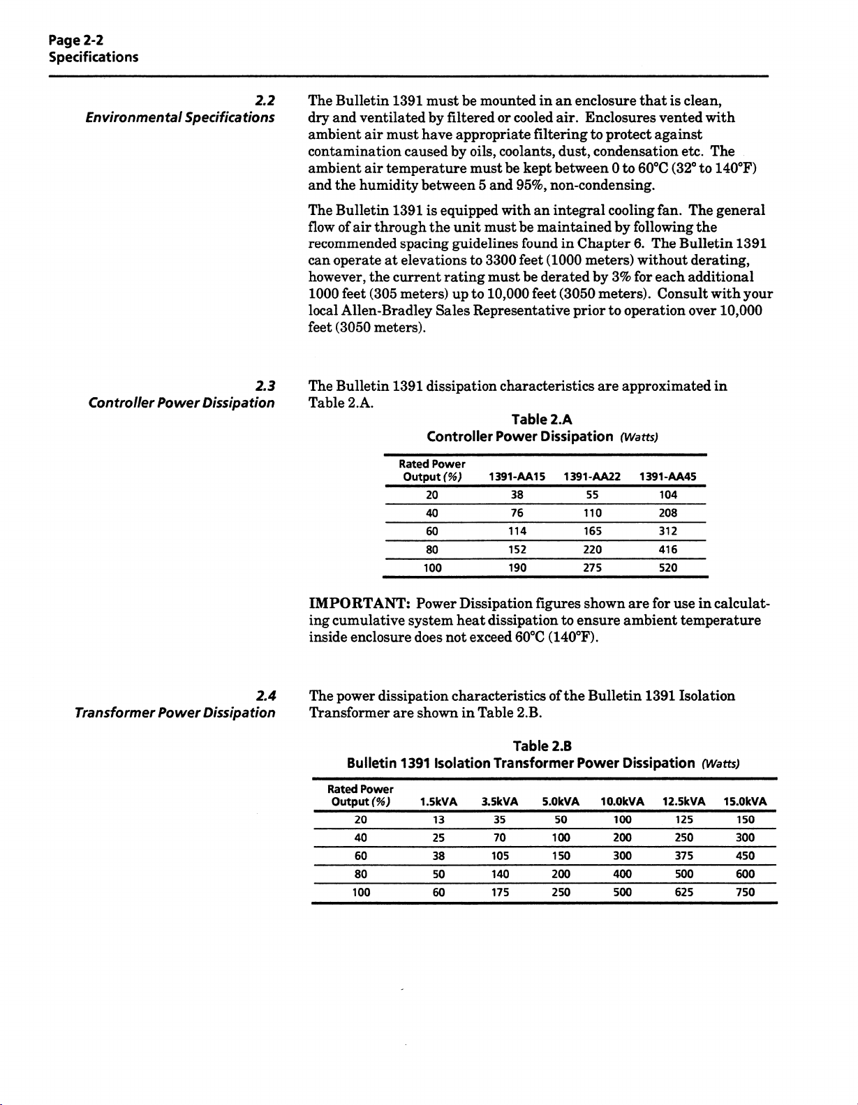
Page
2-2
Specifications
Environmental
Controller
Power
2.2
Specifications
2.3
Dissipation
Bulletin
The
dry
and
ventilatedbyfiltered
ambient
air
contamination
ambient
and
the
The
Bulletin
flow
of
temperature
air
humidity
through
air
recommended
operate
can
however,
feet
1000
Allen-Bradley
local
(3050
feet
The
Bulletin
Table
at
the
(305
meters).
2.A.
1391
must
have
caused
between
1391
spacing
elevations
current
meters)
1391
Rated
Output
100
must
mounted
be
appropriate
by
oils,
must
5
equipped
is
the
unit
guidelines
to
rating
up
to
Representative
Sales
dissipation
Controller
Power
(%)
20
40
60
80
in
or
cooled
filtering
coolants,
kept
be
95%,
and
with
an
must
be
maintained
found
(1000
feet
3300
be
must
10,000
derated
feet
characteristics
Table
Power
1391-AA15
Dissipation
38
76
114
152
190
an
enclosure
Enclosures
air.
to
dust,
condensation
between
protect
60°C
to
0
that
non-condensing.
integral
in
(3050
cooling
by
following
Chapter
meters)
priortooperation
6.
without
3%
by
for
meters).
approximated
are
2.A
(Watts)
1391-AA22
55
110
165
220
275
1391-AA45
is
vented
against
etc.
(32°
fan.
The
Bulletin
each
Consult
104
208
312
416
520
clean,
with
The
140°F)
to
general
The
the
derating,
additional
with
10,000
over
in
1391
your
Transformer
Power
2.4
Dissipation
IMPORTANT:
ing
cumulative
inside
enclosure
dissipation
power
The
Transformer
are
Bulletin
Rated
Power
(%)
Output
20
40
60
80
100
Power
system
does
shown
1391
1.5kVA
Dissipation
dissipation
heat
exceed
not
characteristics
Table
in
Isolation
3.5kVA
13
25
38
50
60
105
140
175
figures
to
(140°F).
60°C
of
2.B.
Table
2.B
Transformer
5.0kVA
35
70
50
100
150
200
250
shown
ensure
the
Power
are
ambient
Bulletin
Dissipation
IQ.OkVA
100
200
300
400
500
for
1391
12.5kVA
in
calculat¬
use
temperature
Isolation
(Watts
15.0kVA
125
250
375
500
625
)
150
300
450
600
750
Page 13
Chapter
3
Chapter
3.0
Objectives
3.1
Receiving
3.2
Unpacking
Chapter3provides
necessary,
and
if
catalog
the
is
it
agent
damage
of
must
inspection
packing
Remove
Inspection
the
against
the
be
section
Bulletin
It
before
item(s)
damaged,
the
concealed
responsibility
container
make
Remove
the
sink
entitled
1391
responsibility
the
is
accepting
received
freight
visual
a
all
controller.
etc.
Receiving,
the
information
store
the
Bulletin
provides
numbering
of
the
shipment
the
responsibility
has
noted
the
be
found
to
user
left
intact
of
material,
packing
all
user
from
purchase
of
damage
during
notify
and
the
equipment.
the
wedges,
Unpacking
needed
1391
a
system.
thoroughly
to
the
the
unpacking,
the
freight
material
to
and
complete
freight
order.
not
user
on
the
freight
agent
or
braces
unpack,
related
explanation
inspect
company.
any
If
items
accept
to
freight
again
is
it
agent.
should
from
from
the
Inspection
and
properly
equipment.
of
equipment
the
Check
are
delivery
Should
bill.
the
shipping
The
be
within
cooling
inspect
The
the
the
obviously
until
any
requested
and
around
fans,
heat
to
3.3
Inspection
3.4
Storing
IMPORTANT:
general
connections,
After
the
included
The
installation.
must
•
•
•
•
•
inspection
unpacking,
purchase
on
the
controller
be
stored
Store
Store
Store
not
Do
atmosphere.
Do
not
clean,
a
in
within
within
store
store
packing
order.
If
Before
mechanical
of
materials,
check
An
following
equipment
the
dry
an
ambient
relative
a
remain
should
according
equipment
equipment
the
installation
item(s)
the
explanation
pages
in
is
to
the
location.
temperature
humidity
where
in
construction
a
integrity
etc.)
must
nameplate
of
the
as
aid
an
shipping
its
not
to
be
following
range
it
could
start-up
and
(i.e.
loose
be
made.
catalog
catalog
nameplate
for
container
for
used
instructions:
range
of
5%
of
to
exposed
be
area.
of
the
parts,
number
numbering
interpretation.
prior
period
a
to
0
65°
non-condensing.
95%,
to
corrosive
a
controller,
wires,
against
system
to
of
time,
(32
to
C
a
is
it
149°F).
Page 14
Page
3-2
Receiving,
Unpacking
and
Inspection
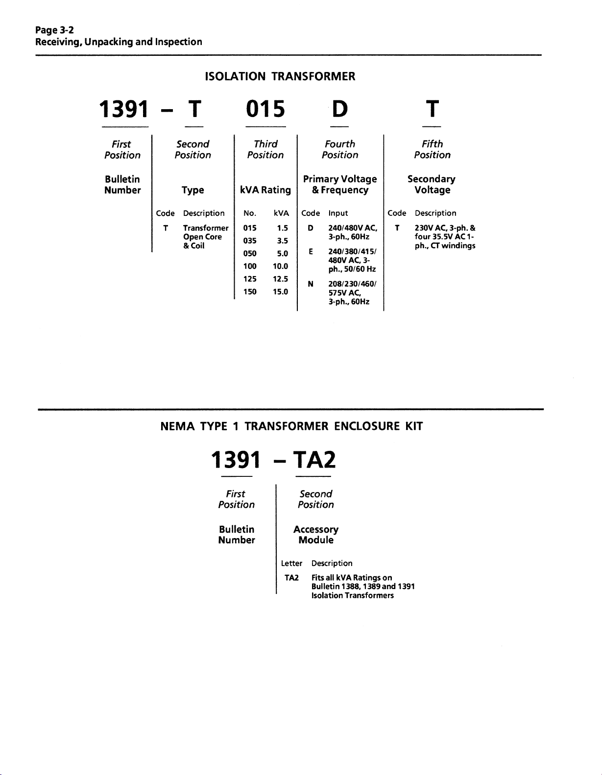
1391
First
Position
Bulletin
Number
Code
T
T
Second
Position
Type
Description
Transformer
Open
&
Coil
ISOLATION
015
Third
Position
Rating
kVA
No.
Core
015
035
050
100
125
150
TRANSFORMER
D
Fourth
Position
kVA
1.5
3.5
5.0
10.0
12.5
15.0
Primary
Code
D
E
N
Frequency
&
input
240/480
3-ph..
240/380/415/
480V
ph..
208/230/460/
575V
3-ph.,
Voltage
VAC,
60Hz
AC,
50/60
AC,
60Hz
T
Fifth
Position
Secondary
Voltage
Description
Code
AC,
35.5V
windings
CT
3-ph.
AC
&
1-
230V
T
four
ph.,
3-
Hz
NEMA
TYPE
1
1391
First
Position
Bulletin
Number
TRANSFORMER
TA2
Second
Position
Accessory
Module
TA2
Description
all
Fits
Bulletin
Isolation
Letter
ENCLOSURE
Ratings
1389
on
and
1391
kVA
1388.
Transformers
KIT
Page 15
Receiving,
Unpacking
and
Page
3-3
Inspection
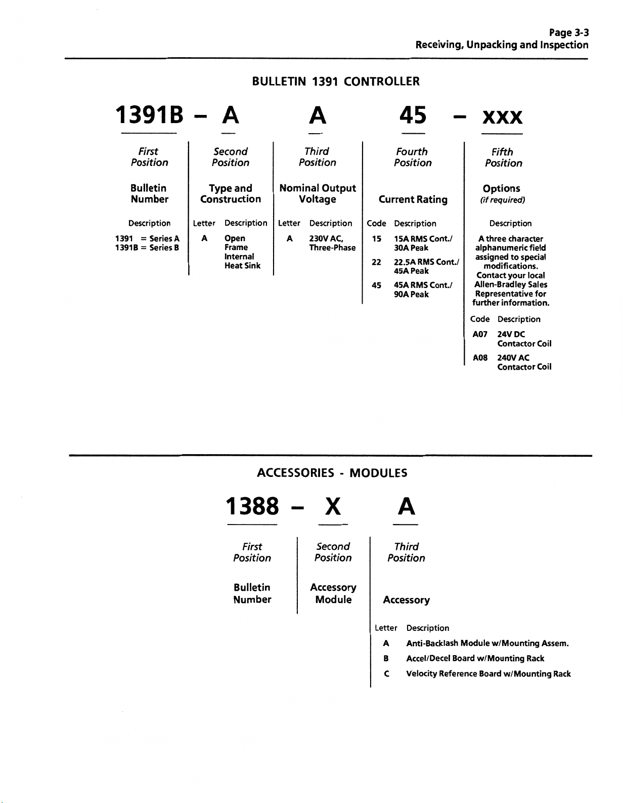
1391B
First
Position
Bulletin
Number
Description
A
=
=
Series
Series
B
1391
1391B
A
-
Second
Position
Type
and
Construction
A
Description
Open
Frame
Internal
Heat
Letter
BULLETIN
Nominal
Letter
A
Sink
1391
A
Third
Position
Output
Voltage
Description
230V
Three-Phase
CONTROLLER
Position
Current
Code
AC,
15
22
45
1
30
22.5A
45A
45A
90A
45
Fourth
Rating
Description
RMS
5A
Peak
A
RMS
Peak
RMS
Peak
Cont./
Cont./
Cont./
XXX
Fifth
Position
Options
(if
required)
Description
three
character
A
alphanumeric
assigned
modifications.
Contact
Allen-Bradley
Representative
further
Code
A07
A08
your
information.
Description
24V
Contactor
240V
Contactor
to
DC
field
special
local
Sales
for
Coil
AC
Coil
ACCESSORIES
1388
First
Position
Bulletin
Number
-
X
Second
Position
Accessory
Module
MODULES
A
Third
Position
Accessory
Letter
A
B
C
Description
Anti-Backlash
Accel/Decel
Velocity
Reference
Module
Board
w/Mounting
w/Mounting
w/Mounting
Board
Assem.
Rack
Rack
Page 16
Page
3-4
Receiving,
Unpacking
and
Inspection
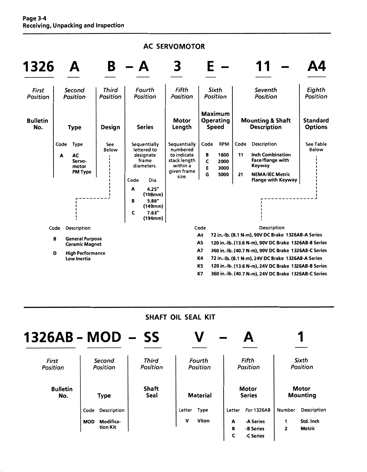
AC
SERVOMOTOR
1326
First
Position
Bulletin
No.
Code
B
D
Second
Position
Code
A
A
Type
Type
AC
Servo¬
motor
Type
PM
Description
General
Ceramic
High
Performance
Inertia
Low
Purpose
Magnet
B
Third
Position
Design
See
Below
A
Fourth
Position
Series
Sequentially
lettered
designate
frame
diameters.
Code
A
(108mm)
B
(149mm)
C
(194mm)
to
Dia.
4.25"
5.88"
7.63"
3
Fifth
Position
Motor
Length
Sequentially
numbered
to
indicate
length
stack
within
a
frame
given
size.
E
Sixth
Position
Maximum
Operating
Speed
Code
B
C
E
G
Code
A4
A5
A7
K4
K5
K7
72
120
360
72
120
360
RPM
1600
2000
3000
5000
in.-lb.
in.-lb.
in.-lb.
in.-lb.
in.-lb.
in.-lb.
Mounting
Code
11
21
(8.1
N-m),
(13.6
(40.7
(8.1
N-m).
(1
3.6
(40.7
11
Seventh
Position
Description
Description
Inch
Combination
Face/flange
way
Key
NEMA/IEC
Flange
Description
DC
90V
N-m),
90V
N-m),
90V
DC
24V
N-m),
24V
N-m),
24V
&
with
Brake
DC
DC
Brake
DC
DC
Shaft
with
Metric
Keyway
Brake
Brake
Brake
Brake
1
326AB-A
1326AB-B
1
326AB-C
1
326AB-A
1
326AB-B
1
326AB-C
A4
Eighth
Position
Standard
Options
See
Table
Below
Series
Series
Series
Series
Series
Series
1326AB
First
Position
Bulletin
No.
MOD
-
Second
Position
Type
Code
MOD
Description
Modifica¬
tion
Kit
SHAFT
SS
Third
Position
Shaft
Seal
OIL
SEAL
Letter
V
KIT
V
Fourth
Position
Material
Type
Viton
Letter
A
B
C
A
Fifth
Position
Motor
Series
For
1
-A
Series
-B
Series
Series
-C
326AB
Mounting
Number
1
2
1
Sixth
Position
Motor
Description
Std.
Metric
Inch
Page 17

Receiving,
Unpacking
and
Page
3-5
Inspection
1
326AB
Bulletin
BRAKE
1326
Bulletin
Number
No.
BLOWER
MOD-
Code
MOD
POWER
MOD
MOD
Type
Description
Modifica¬
tion
Kit
SUPPLY
Type
KIT
G3
Description
Code
Motor
Rear
G3
for
G4
side
for
RECTIFIER
-
BPS
Description
Mount
C
Series
Mount
"C"
Series
Series
Blower
Motors
Blower
Motors
Standard
Motor
H
Motor
Junction
with
Box
Kit
r\
1326AB
Bulletin
Alternate
(Customer
Position
Selected)
IMPORTANT:
mounted
axially
out
MOTOR
No.
The
radially
motor
to
to
the
motor
Code
MOD
JUNCTION
MOD
-
Type
Code
MOD
standard
comes
the
motor.
without
This
further
Description
Modifica¬
tion
Kit
BOX
Description
Modifica¬
*
tion
Kit
with
allows
kit
wiring.
Code
BPS
KIT*
RJAB
-
Description
Code
RJAB
RJBC
IP65
plug
the
connectors
Description
Single-Phase,
Rectifier.
Supplies
brakesonBulletin
Description
All
For
AB-B
Series
For
AB-B4
AB-Cx
style
Full-Wave,
5V
11
power
AB-Aand
Motors
and
Series
Motors
connectors
brought
to
be
AC
for
Input,
up
1
326AB
to
Panel
90V
four
or
Mounted
Output
DC
90V
AD
motors.
DC
*
Kit
includes
Motor
Junction
Box
and
Mounting
Hardware
Page 18
Page
3-6
Receiving,
Unpacking
and
Inspection
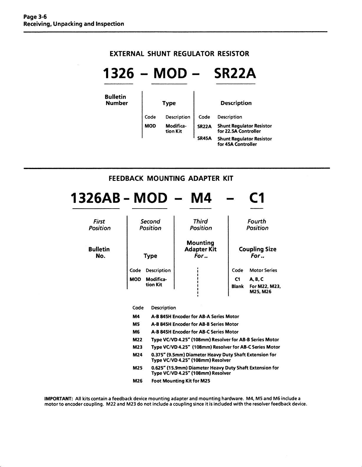
EXTERNAL
1326
Bulletin
Number
FEEDBACK
1326AB
First
Position
MOD
-
Second
Position
SHUNT
REGULATOR
MOD
Type
Code
MOD
MOUNTING
Description
Modifica¬
Kit
tion
RESISTOR
-
SR22A
Code
SR22A
SR45A
Description
Shunt
for
Shunt
for
ADAPTER
M4
Third
Position
Description
Regulator
Controller
22.5A
Regulator
Controller
45A
KIT
Resistor
Resistor
C1
Fourth
Position
IMPORTANT:
motor
encoder
to
All
Bulletin
No.
kits
contain
coupling.
a
feedback
M22
and
Code
MOD
M23
Code
M4
M5
M6
M22
M23
M24
M25
M26
device
do
Type
Description
Modifica¬
tion
Kit
Description
845H
A-B
845H
A-B
A-B
845H
Type
Type
0.375"
Type
0.625"
Type
Foot
mounting
not
include
Encoder
Encoder
Encoder
VC/VD
VC/VD
(9.5mm)
VC/VD
(1
5.9mm)
VC/VD
Mounting
adapter
coupling
a
Mounting
Adapter
for
4.25"
4.25'
Diameter
4.25"
Diameter
4.25"
Kit
and
For..
AB-A
for
AB-B
AB-C
for
(108mm)
(108mm)
(108mm)
(108mm)
for
M25
mounting
since
it
Kit
Series
Series
Series
Resolver
Resolver
Heavy
Resolver
Heavy
Resolver
is
included
Code
C1
Blank
Motor
Motor
Motor
for
for
Duty
Shaft
Duty
Shaft
hardware.
with
Coupling
For..
Motor
A,
B.C
M22, M23,
For
5,
M2
Series
AB-B
Series
AB-C
Extension
Extension
M4,
M5
resolver
the
Size
Series
M26
Motor
Motor
and
for
for
M6
include
feedback
a
device.
Page 19
Receiving,
Unpacking
and
Page
3-7
Inspection
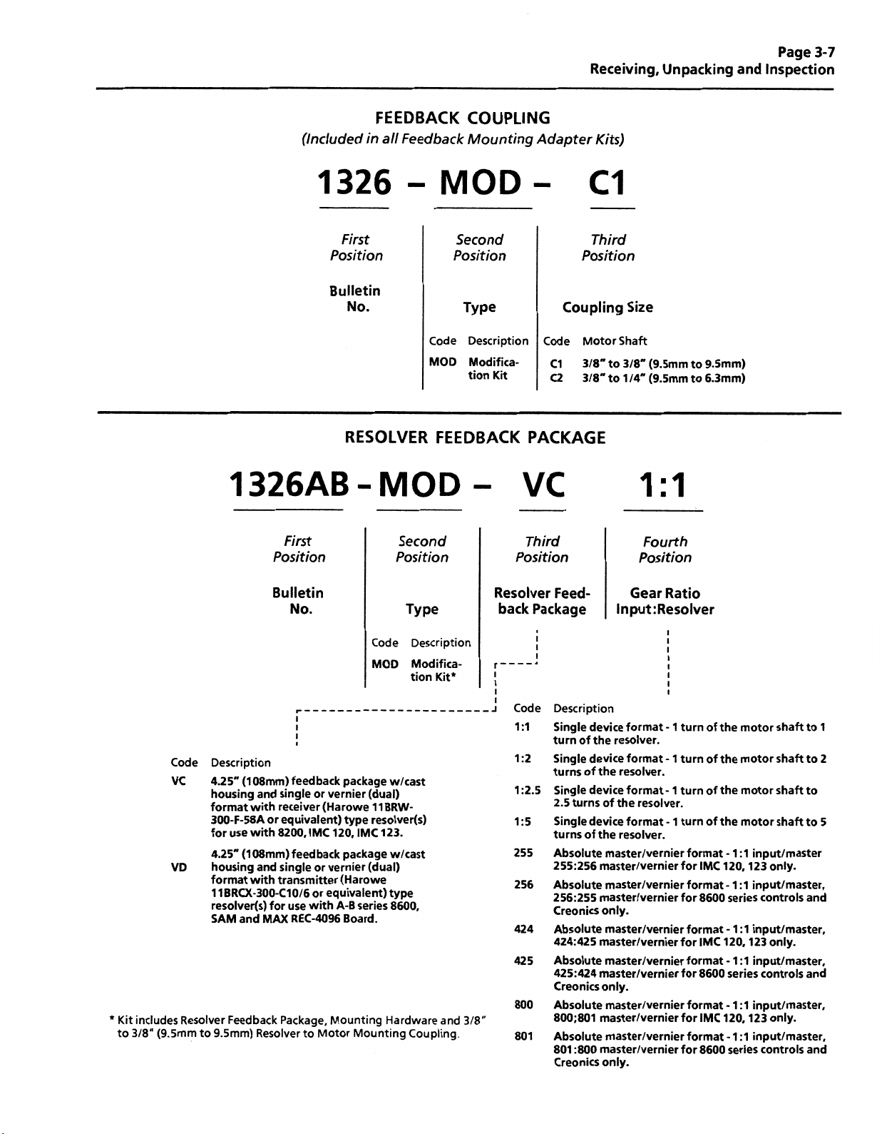
(Included
1326
First
Position
Bulletin
1326AB
FEEDBACK
in
Feedback
all
-
No.
RESOLVER
MOD
-
COUPLING
Mounting
MOD
Second
Position
Type
Description
Code
MOD
Modifica¬
tion
Kit
FEEDBACK
Adapter
C1
Position
Coupling
Motor
Code
C1
3/8"to3/8"
C2
3/8"
PACKAGE
VC
Kits)
Third
to
Size
Shaft
(9.5mmto9.5mm)
(9.5mmto6.3mm)
1/4"
1:1
*
Kit
includes
(9.5mmto9.5mm)
3/8"
to
Code
VC
VD
Resolver
First
Position
Bulletin
Description
(108mm)
4.25"
housing
format
300-F-58A
use
for
4.25"
housing
format
1BRCX-300-C10/6
1
resolver(s)
SAM
Feedback
(1
and
with
with
08mm)
with
single
and
receiver
equivalent)
or
8200,
single
and
transmitter
for
MAX
Package,
Resolver
No.
i
i
i
feedback
or
vernier
(Harowe
IMC
feedback
or
vernier
equivalent)
or
use
with
REC-4096
Mounting
Motor
to
package
type
120,
package
(Harowe
A-B
Board.
Code
MOD
w/cast
(dual)
11BRW-
resolver(s)
IMC
123.
w/cast
(dual)
type
8600,
series
Hardware
Mounting
Second
Position
Type
Description
Modifica¬
tion
Kit*
Coupling
and
3/8"
Third
Position
Resolver
Package
back
r~~
i
i
i
i
J
Code
1:1
:2
1
1
:2.5
:
1
5
255
256
424
5
42
800
801
Feed¬
i
i
i
Description
Single
turn
Single
turns
Single
2.5
Single
turns
Absolute
255:256
Absolute
256:255
Creonics
Absolute
424:425
Absolute
425:424
Creonics
Absolute
800:801
Absolute
801
Creonics
device
of
the
device
of
the
device
turns
of
device
the
of
master/vernier
master/vernier
master/vernier
master/vernier
only.
master/vernier
master/vernier
master/vernier
master/vernier
only.
master/vernier
master/vernier
master/vernier
:800
master/vernier
only.
Fourth
Position
Gear
Ratio
lnput:Resolver
format
resolver.
format
resolver.
format
resolver.
the
format
resolver.
-
-
-
-
1
1
1
1
turn
turn
turn
turn
format
for
format
for
format
for
format
for
format
for
format
for
of
of
of
of
IMC
8600
IMC
8600
IMC
8600
the
the
the
the
-1:1
120,
-1:1
series
-1:1
120.
-
series
-1:1
120.
-1:1
series
motor
motor
motor
motor
1:1
shaft
shaft
shaft
shaft
input/master
only.
123
input/master,
controls
input/master.
only.
123
input/master,
controls
input/master,
only.
123
input/master,
controls
to
to
to
to
and
and
and
1
2
5
Page 20
Page
3-8
Receiving,
Unpacking
and
Inspection
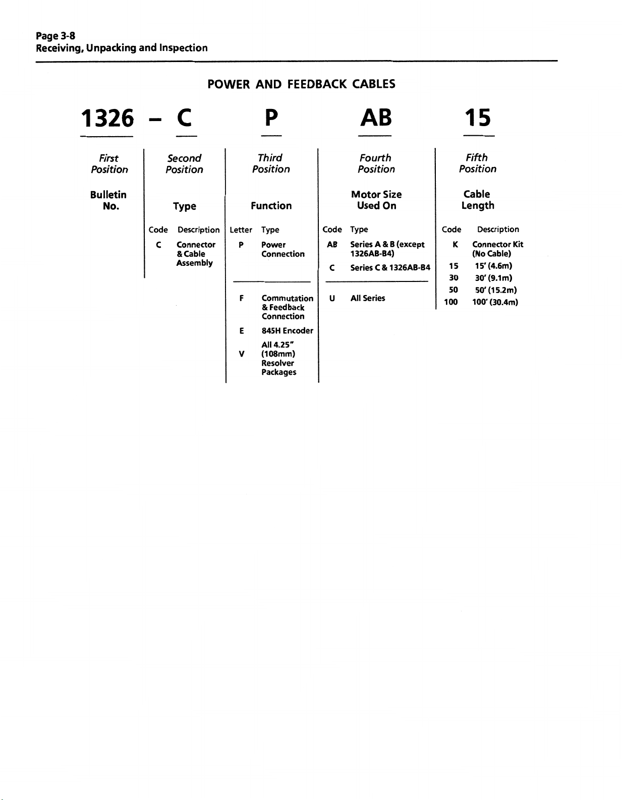
1326
First
Position
Bulletin
No.
Code
C
C
Second
Position
Type
Description
Connector
Cable
&
Assembly
POWER
Letter
P
F
E
V
AND
P
Third
Position
Function
Type
Power
Connection
Commutation
&
Feedback
Connection
845
H
Encoder
4.25"
All
(108mm)
Resolver
Packages
FEEDBACK
Code
AB
C
U
CABLES
AB
Fourth
Position
Motor
Type
Series
1326AB-B4)
Series
All
Size
Used
On
&
A
C&1326AB-B4
Series
B
(except
Code
15
30
50
100
15
Fifth
Position
Cable
Length
K
Connector
(No
100'
Description
Cable)
(4.6m)
15'
(9.1m)
30'
(15.2m)
50’
(30.4m)
Kit
Page 21
Chapter
4
300V
Chapter
DC
Power
PWM
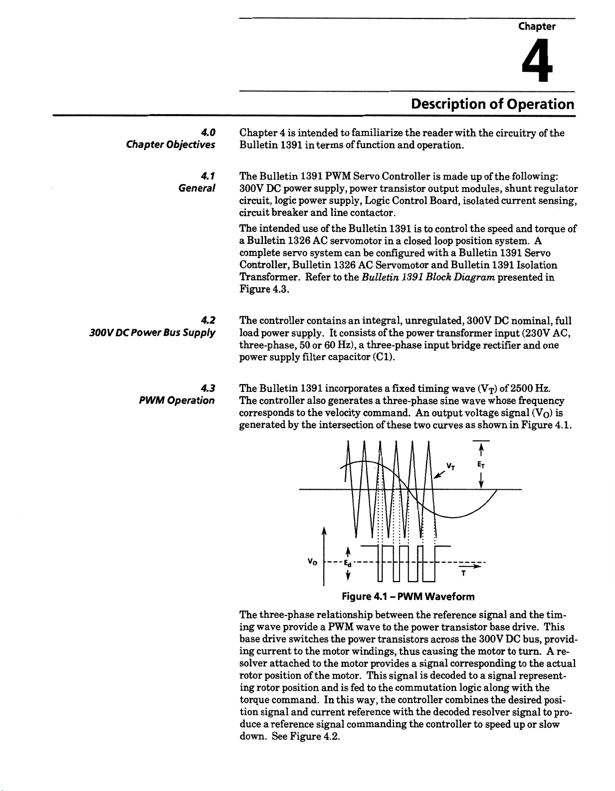
4.0
Objectives
4.1
General
4.2
Supply
Bus
4.3
Operation
Chapter
Bulletin
The
300V
circuit,
circuit
The
Bulletin
a
complete
Controller,
4
is
1391
Bulletin
power
DC
logic
breaker
intended
1326
servo
Transformer.
Figure
The
load
three-phase,
power
The
The
corresponds
generated
4.3.
controller
power
supply.
supply
Bulletin
controller
by
intended
in
terms
1391
supply,
power
and
use
of
AC
system
Bulletin
Refer
contains
or
50
filter
1391
also
to
the
the
intersection
to
familiarize
of
function
Servo
PWM
power
supply,
line
the
Logic
contactor.
Bulletin
servomotor
can
be
AC
1326
to
the
Bulletin
integral,
an
consists
It
Hz),
three-phase
60
capacitor
incorporates
a
generates
velocity
command.
Description
the
and
Controller
transistor
Control
1391
is
closed
a
in
configured
Servomotor
1391
unregulated,
power
the
of
(Cl).
fixed
a
three-phase
a
An
two
these
of
reader
operation.
made
is
output
Board,
to
control
loop
with
a
and
Bulletin
Block
transformer
input
timing
wave
sine
output
curves
with
the
up
modules,
isolated
the
position
Bulletin
Diagram,
300V
bridge
(Vj)
wave
voltage
shown
as
Operation
of
circuitry
following:
the
of
shunt
current
speed
system.
1391
1391
presented
nominal,
DC
input
rectifier
of
2500
whose
signal
in
of
regulator
sensing,
torque
and
A
Servo
Isolation
in
(230V
and
one
Hz.
frequency
(Vo)
Figure
the
of
full
AC,
is
4.1.
three-phase
The
ing
wave
base
drive
ing
current
solver
rotor
position
ing
rotor
torque
signal
tion
duce
a
down.
V0
relationship
provide
switches
to
attached
position
command.Inthis
and
reference
Figure
See
a
the
to
the
of
and
current
signal
PWM
the
motor
the
motor.
4.2.
Figure
motor
4.1
between
wave
power
transistors
windings,
provides
to
This
to
fed
way,
the
the
is
reference
commanding
*
PWM
-
the
signal
with
Waveform
the
power
across
causing
thus
signal
a
decoded
is
commutation
controller
the
controller
the
VT
reference
transistor
the
the
corresponding
to
logic
combines
decoded
f
\
signal
base
300V
motor
signal
a
along
the
resolver
speed
to
the
and
drive.
bus,
DC
to
turn.
to
the
represent¬
with
desired
signal
up
or
tim¬
This
provid¬
A
actual
the
posi¬
to
slow
re¬
pro¬
Page 22
Page
4-2
DescriptionofOperation
PWM
4.3
Operation
(Continued)
CURRENT
REFERENCE
COMMUTATION
LOGIC
CURRENT
&
LOOP
INTEGRATOR
Figure
POSITION
DECODER
4.2
-
PWM
GENERATOR
&BASE
DRIVE
IAM1
TIMING
SIGNAL
GENERATOR
Operation
Shunt
Regulator
4.4
Operation
The
Bulletin
regenerative
exceeds
motor
regulator
activates
the
placed
conditions.
dissipated
the
repeats,
too
If
increase
to
voltage
the
shunt
in
series
transistor
provided
much
level,
condition
The
shunt
cycle
timer.
SW1,
determines
at
a
which
selector
the
controller
would
for
9
equivalent
be
further
1391
shunt
conditions
which
that
monitors
resistor
When
at
shunt
with
the
off
the
regulator
and
the
the
resistor,
when
the
regenerative
even
with
the
Bulletin
exists,
and
regulator
The
timer
switch
temperature
the
behavior
controller
willbeforced
to
regulator
shunt
regulator
when
the
can
be
voltage
bus
transistor,
dissipating
resistor
shunt
transistor
the
bus
voltage
the
voltage
bus
energy
the
shunt
1391
trip
out
on
is
usedtomodel
is
locatedonthe
level
trip
will
trip
to
turning
out
information.
provides
energy
storedinthe
and
power
protect
to
voltage
reaches
continuestoincrease
present,
is
regulator
will
determine
Overvoltage
an
further
and
When
out.
on
the
shunt
power
returned
predetermined
at
a
allowing
in
the
it
activated
is
will
the
the
on.
modified
the
shunt
top
the
of
therefore
this
Overvoltage
an
regulator
bus
form
against
quickly
“OFF”
bus
At
that
Fault.
controller
the
level
dissipation
to
the
controllerbythe
capacitors.
“ON”
current
and
voltage
predetermined
a
by
resistor
to
heat.
of
short
power
decrease,
point.
the
to
overvoltage
an
adjustable
an
temperature.
(see
average
reached,
is
circuit
will
Fault.
Refer
off.
for
The
flow
fuse
A
being
is
turning
This
“ON”
continue
Figure
power
the
This
Chapter
to
shunt
point
through
is
cycle
point.
bus
duty
1.1)
level
action
Logic
Logic
wer
Po
Control
upply
5
Board
4.S
4.6
control
The
Bulletin
voltages
The
Boards,
winding
Logic
The
accessible
circuits
velocity
the
power-up/power-down
controlling
1391
are
which
receive
the
on
isolation
Control
behind
necessary
and
circuits.
generated
Board
the
to
current
logic
35.5V
a
transformer.
the
is
front
cover
control
loop,
logic,
on
the
AC
the
fault
PWM
voltage
is
Power
center-tapped
printed
of
the
circuit
controller.
Bulletin
detection
generation
12V
±
Driver
1391.
and
DC
and
Logic
and
input
from
that
board
This
These
and
circuits
annunciation
forward/reverse
5V
+
Control
readily
is
board
DC.
tertiary
a
contains
include:
circuits,
all
Page 23
Description
Page
Operation
of
4-3
Circ
S£[—
Brea
Isolation
Transformer
MPT
Primary
A
Y
Secondary
Line
AC
Input
TBS-4
TB5-5
Contactor
Contactor
35.5V
AC.
115V
1
$.CT
Coil
AC
Velocity
Command
Rectifier
TTi
Control
Protecti
Circuitry
Logic
Control
D1
Her
ion
External
Current
Limit
Board
Power
Control
Tach
Output
JS
Shunt
Regulator
Driver
Logic
I
Command
Output
External
Regulator
Transistor
Base
Board
Adjustments
Offset
0
I
0
Limit
Gain
0
Comr
0
Scale
Shunt
Resistor
mand
Enable
Drive
IBS.
Power
Logic
LED's
Overtemp
Power
Fault
Control
Power
Overvoltage
Undervoltage
Current
Foldback
Enable
Ready
Reset
Supply
Contact
Transistor
StS
DROK
Power
Protect
through
TB1-10
Output
Fault
Sion
lated
Iso
Cu
rrent
Sense
Board
Modules
Bulletin
1326
Permanent
MagnetAC
Servomotor
O
Brushless
Resolver
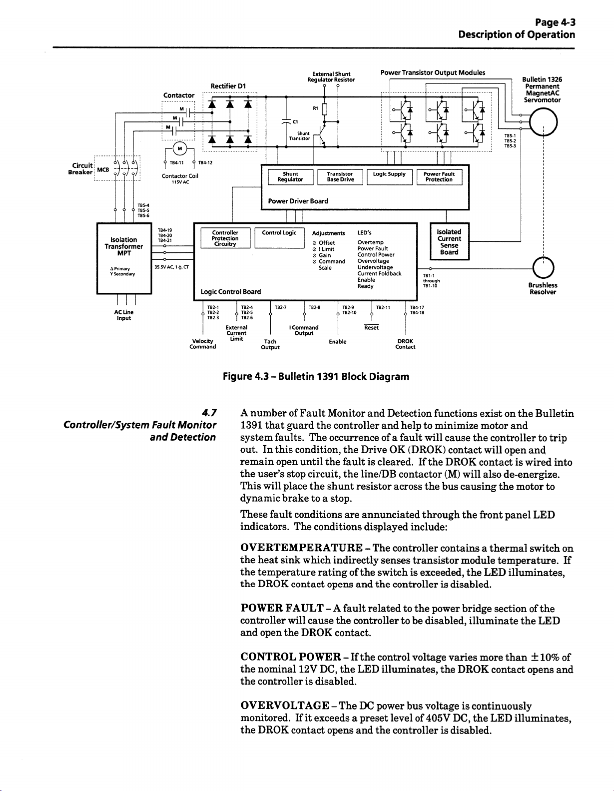
Controller/System
Fault
and
4.7
Monitor
Detection
Figure
4.3-
A
number
1391
that
system
out.
remain
the
This
faults.
In
this
open
user’s
will
dynamic
These
fault
indicators.
Bulletin
of
Fault
guard
condition,
until
stop
circuit,
place
brake
conditions
The
1391
the
The
the
to
conditions
OVERTEMPERATURE
the
heat
sink
which
temperature
the
DROK
the
POWER
FAULT
controller
open
and
the
CONTROL
the
nominal
the
controllerisdisabled.
contact
will
cause
DROK
POWER
12V
rating
Block
Monitor
controller
occurrence
the
Drive
the
faultiscleared.
the
line/DB
shunt
resistor
stop.
a
are
annunciated
indirectly
of
the
opens
and
A
fault
-
the
controllertobe
contact.
If
the
-
DC,
the
LED
Diagram
and
Detection
help
fault
(DROK)
to
will
and
of
OK
a
If
contactor
across
the
through
displayed
The
-
switch
the
related
control
include:
controller
senses
transistor
exceeded,
is
controllerisdisabled.
to
the
voltage
illuminates,
functions
minimize
cause
contact
DROK
the
(M)
bus
contains
power
disabled,
varies
DROK
the
exist
motor
the
controller
will
contact
will
also
causing
the
front
a
thermal
module
the
LED
bridge
illuminate
more
contact
the
on
Bulletin
and
to
open
and
wired
is
de-energize.
the
motor
panel
LED
switch
temperature.
illuminates,
than
the
of
±
the
LED
10%
section
opens
trip
into
to
on
If
of
and
OVERV
OLTAGE
monitored.
DROK
the
If
exceeds
it
contact
The
-
opens
DC
preset
a
and
power
level
the
controllerisdisabled.
bus
voltage
405V
of
continuously
is
DC,
the
LED
illuminates,
Page 24
Page
4-4
Description
Operation
of
Controller/System
Fault
and
4.7
Monitor
Detection
(Continued)
UNDER
nominal
present
DROK
further
VOLTAGE
operating
TB2-13.
at
contacts
information.
IMPORTANT:
transistor
done
CURRENT
current
output
the
LED
condition
RUN/
position
DRIVE
monitored
are
LED
DROK
bridge
protect
to
overload
bridge.
illuminated
is
will
ENABLE
controller
READY
not
will
contact
FOLDBACK
If
-
value,
jumper
A
undervoltage
to
an
Regardless
disabled
is
output
the
circuit
fixed-time
a
If
and
reduce
continuously.
be
the
application
The
-
cause
will
The
-
illuminated,
be
open.
will
the
DC
the
setting
of
upon
transistors
The
-
which
signal
a
current
the
status
If
a
power
LED
illuminates
selects
detection.
interaction
undervoltage
an
against
controller
monitors
versus
will
be
limit
of
an
RUN
power
the
of
fault
a
signal
fault
voltage
bus
and
the
reaction
Refer
with
the
voltage
contains
current
the
current-product
present
or
enable
ENABLE
present,
is
torque
supplies
will
at
availabletothe
signal
LED
the
be
drops
below
signal
a
of
to
section
DROK
condition.
transients.
fixed
a
through
is
TB2-14.
by
the
to
illuminate.
and
fault
DRIVE
present
50%
will
be
the
5.3
contacts,
This
time
each
exceeded,
This
motor.
machine
conditions
READY
TB4
at
of
for
the
is
versus
leg
and
its
of
the
the
Isolated
Integral
Current
Circuit
Line/DB
4.8
Sensing
4.9
Breaker
4.10
Contactor
Logic
The
Current
inverter
The
by
an
utilizes
The
the
operation
when
energized
Control
Sense
thermal
integral
three
a
connected
in
contactor
the
except
logic
control
three-phase
input
conjunction
transformer.
IMPORTANT:
not
is
that
continuous
cycle
this
Representative
be
to
basis.
exceeded.
is
receives
Board
Board.
circuit
pole
This
protection
power
and
breaker.
magnetic
incoming
to
terminals
AC
with
disabled.
is
voltage
when
Bulletin
The
energized/de-energized
life
of
The
Contact
additional
for
current
circuitry
power
and
circuitry
TheDCbus
circuit
line
11
the
shunt
The
is
removed
1391
contactor
the
your
information.
also
fault
are
breaker.
opened
is
12
and
Logic
contains
more
local
by
the
TB4
the
definite
a
than
be
from
the
against
and
is
reduces
Board
twice
reduced
feedback
provides
sensing.
protected
supply
of
regulator
Control
from
may
Allen-Bradley
the
used
data
overcurrents
input
contactor
removed.
the
remains
incoming
purpose
an
considerably
Sales
Isolated
for
rectifier
whenever
This
bus
isolation
contactor
hour
on
voltage
a
if
Power
Driver
4.11
Board
The
power
Power
transistor
Driver
Board
modules.
contains
the
circuitry
needed
to
switch
the
Page 25
Starting
and
4.12
Stopping
A
WARNING:
includes
contact
liquid,
stop
applicable
and
power
of
this
explanations
solid-state
with
gas
or
circuit
to
additional
when
controller.
The
Enable
moving
solids
may
a
required.
be
particular
your
information.Adevice
contingency
Refer
below.
control
components.
machinery
exist,
to
an
stop
the
additional
system
Description
circuitry
If
hazards
or
unintentional
to
Refer
for
is
initiated
individual
in
due
hardwired
the
codes
specific
removes
that
is
stop
Operation
of
the
Bulletin
to
accidental
flow
contingency
and
standards
requirements
AC
integral
an
mode
Page
of
input
4-5
1391
part
WARNING:
termine
A
Starting
elements
are
outlined
tion
and
as
shown
below.
information.
control
CAUSE
De-energize
Speed
Open
DROK
Dynamic
the
during
energized.
regulator
voltage
Command
Enable
Opens
control
the
Line/DB
Input
(Fault)
Braking
circuitry,
DC
The
resistor
IMPORTANT:
motor
the
that
will
follows.
which
and
will
Stopping
in
Refer
effects
The
not
has
Contactor
brought
-
decay,
bus
dynamic
and
Frequent
reduce
The
stopping
meet
must
be
Appendix
to
described
been
(M)
to
Zero
When
the
inherent
an
provided
braking
total
load
cycling
the
lifeofthe
has
user
applicable
accomplished
the
de-energized.
Coil
the
methodisbest
Stopping
B.
paragraphs
below
EFFECT
Dynamic
Regenerative
Regenerative
Coast
line/DB
inertia.
contactor
dynamic
35.5V
the
depends
effect
the
of
contactor.
ultimate
standards
by
modes
that
assume
ON
MOTOR
Brake
Brake
Brake
Stop
to
braking
AC
line/DB
Refer
responsibility
for
to
operator
suited
hardwired
the
for
follow
logic
on
that
(M)
effect
the
is
for
the
de-energized
voltage
valueofthe
contactor
to
the
applica¬
the
safety.
user
Bulletin
detailed
35.5V
will
occur
is
start/stop
to
paragraph
to
de¬
supplied
1391
AC
by
not
de¬
shunt
Power-Up/Down
4.13
Sequence
Regenerative
performed
supplied
applied,
contact
will
cause
been
energized,
in
regenerative
a
450ms.
Coast
only
will
(M)
coil
Figure
sequence
through
control
mechanical
a
closure
the
energized
the
An
-
occur
the
or
4.4
describes
of
Braking
circuitry.
(open
controller
by
maximum
internal
the
if
Enable
the
Bulletin
the
Enable
contact
collector,
the
control
stopping
controller
DROK
input
the
Normal
-
Refer
closure
run,
to
circuitry.
available
mode,
contact
circuits.
various
1391
controller.
run
input
Appendix
to
to
15
+
provided
reverse
which
opens
fault
is
steps
commands
any
and
between
+
not
30V
the
When
torque
will
the
wired
additional
With
B.
TB2-9
DC)
line/DB
the
occur
DROK
to
involvedinthe
to
controller
the
customer
input
10
&
or
between
TB2-10
contactor
Enable
is
for
input
applied
approximately
contact.
line/DB
the
power-up/down
are
power
solid-state
&
(M)
has
de¬
is
to
motor
the
Coasting
contactor
12
Page 26

Page
4-6
Description
Operation
of
POWER-UP
APPLICATION
a)
Logic
up.
b)
Apply
c)
Power
d)
If
no
energizes.
enable
a)
Base
command
ENABLE
a)
When
detect
Random
b)
Re-application
controller
will
Of
power
115V
bus
faults
signal.
Minimum
drive
SIGNAL
35.5V
that
fault
energize
240V
supplies
AC
to
contactor.
charges.
encountered,
are
Controller
ENABLE
of
100ms
enabled
inputs.
IS
APPLIED
power
AC
the
enable
conditions
of
enable
with
and
the
controller.
SEQUENCE
I
AC
TO
and
ready
is
SIGNAL
after
and
will
PRIOR
applied,
is
signal
occur.
after
35.5V
ISOLATION
base
drive
circuits
DROK
the
to
receive
APPLIED
TO
fault
already
is
resetting
power
is
to
35.5V
still
Contactor
respond
AC
TRANSFORMER
power-
relay
customer
Closed
customer
AC
POWER
circuits
applied.
the
present,
Fault
-
i
Fault
---
i
¥
Fault
Fault
!
Fault
-*ÿ-
POWER-DOWN
a)
b)
c)
a)
b)
will
Motor
Output
DROK
Logic
zero
power
relay
and
volts.
Undervoltage
ENABLE
regenerate
stage
maintains
AC
240V
DC
link
(fault)
I
SIGNAL
to
is
disabled.
a
POWER
power
condition
SEQUENCE
REMOVED
stop.
a
fault
no
status.
REMOVED
supplies
occurs.
begin
decaying
to
a)
Controller
b)
DROK
c)
If
contactor
contingency
the
supply.
Figure
relay
shunt
FAULT
CONDITION
output
stage
de-energized
is
wiredtothe
is
stop
string,
regulator
Power-Up/Down
4.4-
Ytt
will
OCCURS
disabled.
and
DROK
contactor
discharge
faultislatched.
a
relay
a
in
open
will
power
the
Sequence
and
bus
Page 27
Chapter
5
Chapter
puts/
In
5.0
Objectives
5.1
Outputs
Chapter
availableonthe
comprehensive
jumper
provided
understand
the
actual
adjustments,
The
inputs
terminal
contains
5
settings
for
installation
following
outputs
and
block
use
some
refer
TERMINAL
Resolver
These
Appendix
Signals
terminals
for
B
descriptions
Bulletin
listing
paragraphs
locations.
BLOCK
connection
provided.
is
during
of
the
Chapter
to
available
(TB1,
used
are
and
and
-
Inputs,
Servo
1391
description
In
start-up.
important
start-up.
9.
provide
for
TB1
Terminals
for
connection
details.
of
the
some
This
aspects
detailed
the
Outputs
various
Controller.
potentiometer,
the
of
adjustment
cases
information
about
For
information
descriptions
Bulletin
1-10)
to
the
and
inputs
Additionally,
is
the
controller
See
1391.
resolver.
Adjustments
outputs
and
a
switch
methods
providedtohelp
on
shunt
of
the
Figure
Refer
and
are
prior
regulator
various
5.1
for
to
you
to
TERMINAL
Velocity
The
achieve
are
source
40k
External
The
current
Leaving
current
(R148).
rated
Tachometer
voltage
A
will
P1
set
2000
RPM
Output
information.
Command
controller
maximum
at
terminals2and
only.
end
(20k
ohms
Current
application
availabletothe
the
or
the
Jumpering
motor
corresponding
present
be
"OUT,"
to
and
3000
will
be
current
BLOCK
accept
will
motor
The
ohms
of
0
terminals
rated
current
Output
between
voltage
a
RPM
present
is
1mA
TB2
-
Input
respectively.
1,
input
single
for
Limit
5V
to
+
motor
open
motor
the
terminals
or
less.
(TB2,
to
this
motors).
(for
5000
maximum.
(TB2,
up
to
a
speed.
impedance
ended
Inputs
DC
at
from
sets
current
Terminal
motor
the
terminal
±2.5V
of
With
RPM
1,
Terminals
10V
±
The
the
DC
(
plus
Shield
of
the
inputs).
(TB2,
Terminals
terminals5and6will
to
20
200%
current
set
value
will
reduce
7)
velocity
and
DC/1000
"IN,"
P1
Bulletin
to
Refer
2,
velocity
)
and
+
must
velocity
the
of
at
limit
with
the
peak
the
and
Signal
Common.
RPM
voltage
a
1326AB-AxG
section
3)
command
minus
(
be
terminated
command
6)
5,
4,
vary
scaled
200%
Current
current
direction
will
be
of
±
for
5.3
signal
)
reference
—
input
the
rating.
of
scaled
Limit
to
of
rotation
With
present
1.5V
DC/1000
motors).
further
to
at
is
peak
motor
pot
20%
of
jumper
(for
Page 28
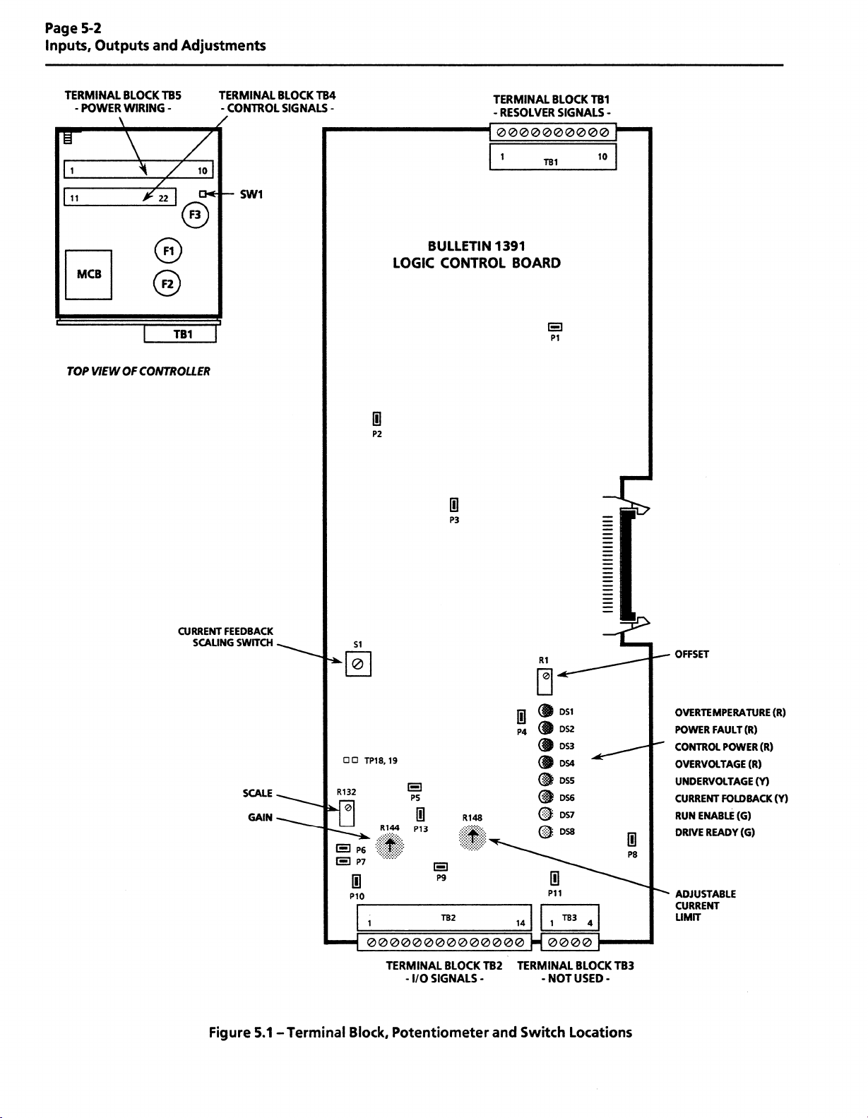
Page
Inputs,
5-2
Outputs
Adjustments
and
TERMINAL
POWER
-
¥
1
11
MCB
TOP
VIEW
BLOCK
TB5
WIRING
\
-
/
©
©
TB1
OF
CONTROLLER
TERMINAL
•CONTROL
SW1
BLOCK
TB4
SIGNALS
-
BULLETIN
LOGIC
CONTROL
TERMINAL
-RESOLVER
0000000000
1
1391
BLOCK
TB1
BOARD
B
P1
TB1
SIGNALS
10
-
1
P2
CURRENT
SCALING
FEEDBACK
SWITCH
SCALE
GAIN
0
P3
SI
©I
TP18,
19
R132
B
B
0
P6
P7
0
P10
B
P5
R144
P13
t
1 1
00000000000000
TERMINAL
I/O
-
R148
I
B
P9
TB2
BLOCK
SIGNALS
TB2
-
R1
1
14
TERMINAL
DS2
P4
DS3
(§&
DS4
DS5
DS6
(§E
DS7
DS8
@
0
P11
183
0000
NOT
-
if
0
P8
4
BLOCK
TB3
USED
-
OFFSET
OVERTEMPERATURE
FAULT
POWER
CONTROL
OVERVOLTAGE
UNDERVOLTAGE
CURRENT
RUN
DRIVE
ADJUSTABLE
CURRENT
LIMIT
POWER
FOLDBACK
ENABLE
READY
(R)
(R)
(R)
(R)
(Y)
(Y)
(G)
(G)
Figure
-Terminal
5.1
Block,
Potentiometer
and
Switch
Locations
Page 29

Inputs,
Outputs
and
Adjustments
Page
5-3
Inputs/
5.1
Outputs
(Continued)
present
equals
Input
Run
input
power
closure
to
(TB2,
the
Common
Output
to
commands
run.
Terminal
I
Command
voltage
The
corresponds
maximum)
Enable
Normal
Enable
With
input
contact
mechanical
a
controller
regenerative
a
Reset
Removing
Signal
to
fault
occurs.
IMPORTANT:
determined
Signal
Signal
and
Common
input
reference
the
motor
the
(TB2,
any
and
applied
(rated
contact
When
braking
Enable
(TB2-12)
Reset
A
corrected.
(TB2,
(TB2,
between
current.
rated
Terminals
to
the
additional
and
to
15
+
closure
this
action
11)
signal
must
Terminal
point.
Terminal
this
terminal
A
motor
currentasset
10)
9,
controller
user
line
the
+30V
between
input
is
the
in
momentarily
and
will
reset
not
be
12)
8)
and
voltage
supplied
of
performed
are
±
rim
contactor
30mA)
DC,
&
TB2-9
de-energized,
10
motor.
connecting
the
controller
initiated
until
Signal
3.0V
by
switch
control
energized,
between
will
the
after
the
Common
(1mA
DC
SI.
through
circuitry.
solid-state
a
TB2-10
cause
the
control
this
controller
a
cause
out
the
12
&
will
cause
terminal
is
or
Low
This
indicate
Current
This
indicate
(TB2,
Bus
terminal
low
a
Foldback
terminal
that
Common.
TERMINAL
Spares
Reserved
(TB3,
for
TERMINAL
Drive
Application
controller.
controller
remains
the
transformer.
Jumper
OK
closed
P8
(DROK)
faults
Terminal
provides
voltage
bus
(TB2,
provides
current
foldback
BLOCK
Terminals
future
use
BLOCK
Contacts
power
of
When
90%
are
to
detected,
untilacontroller
Contact
page
on
5-10
13)
open
an
condition.
Terminal
open
an
TB3
-
1-4)
and
are
TB4
-
the
transformer
of
rated
rating:
further
for
collector
collector
operation.
is
in
not
(TB4,
DC
Bus
relay
this
fault
115V
output
Reference
14)
output
to
be
used.
Terminals
energizes
voltage
contact
occurs
information.
AC,
or
1A
rated
at
Signal
to
rated
at
Reference
18)
17,
logic
the
is
achieved
closed.
is
power
or
24V
is
DC,
DC,
12V
Common.
DC,
12V
Signal
to
supply
and
no
The
contact
removed
0.3A.
5mA
5mA
the
of
from
Refer
to
to
to
35.5V
The
winding
brought
connectedtoterminal
Logic
AC
isolation
supplies
out
Supply
transformer
35.5V
to
terminals
AC
20
Voltage
contains
with
and
19
TB4.
of
center
a
21
See
(TB4,
four
TB4.
of
Chapter
Terminals
separate
tap.
The
The
9
19,
windings.
35.5V
center
for
transformer
tap
20,
AC
21)
Each
leads
must
are
be
details.
Page 30

Page
Inputs,
5-4
Outputs
and
Adjustments
Potentiometer
puts/
In
Outputs
(Continued)
Adjustments
5.1
5.2
TERMINAL
Motor
Motor
Appendix
Input
The
supplied
Appendix
External
The
resistor
applications
the
at
application
The
be
operation.
Preliminary
required
Initially
Figure
Power
power
B
Power
controller
by
B
Shunt
22.5A
to
DC
Bus.
terminals
shunt
externally
as
the
5.1
controllers
supplement
regulator
Refer
for
BLOCK
Terminals
provided
is
connection
for
Terminals
requires
transformer
the
for
wiring
and
Regulator
have
the
require
that
To
use
an
10
of
8
and
assistance.
resistor
mounted
Chapter
to
adjustment
explained
potentiometers
potentiometer
below.
TB5
-
at
(TB5,
these
Terminals
terminals.
1,
Refer
details.
(TB5,
Terminals
three-phase,
AC,
230V
a
secondary.
transformer
Resistor
provisions
integral
the
external
TB5.
unit.
dissipation
shunt
Consult
supplied
connectedtoterminals8and
and
Appendix
and
9
Logic
be
Control
set
the
of
Descriptions
shall
4,
Refer
information.
(TB5,
accept
to
Thisisavailable
more
of
resistor,
Allen-Bradley
the
with
the
B
Board
the
of
showninTable
as
locations.
3)
2,
Chapter
to
6)
5,
50or60
Chapters
to
Terminals
external
an
regenerative
first
remove
Bulletin
for
details.
potentiometers
potentiometers
and
6
input
Hz
6,
and
9
10)
8,
9,
shunt
for
energy
jumper
the
sales
office
1391-AA45
TB5
prior
of
9
follow.
See
5.A.
to
for
must
to
is
Potentiometer
Limit
Current
Velocity
Offset
Current
This
the
rating
3V
Velocity
This
system.
amplifier,
Gain
(R1)
Limit
single
servomotor.
and
100%
DC
=
potentiometer
Clockwise
conjunction
adjusted
be
can
Offset
Adjustment
(Rl)
(R148)
(R144)
and
turn
can
Gain
while
with
for
Potentiometer
Initial
(R132)
Scale
(R148)
potentiometer
The
maximum
calibrated
be
used
motor
to
increases
continuous
(R144)
is
rotation
counterclockwise
velocity
the
range.
wide
over
a
system
offset
Table
Setting
Fully
counterclockwise
counterclockwise,
Fully
Leave
at
becomes
adjusts
setting
tuned)
(fine
current.
tune
fine
rotation
plug
loop
voltages
5.A
present
the
necessary
the
maximum
200%
is
using
response
the
dynamic
the
decreases
jumper
provided
is
Settings
then
setting
the
in
of
TP21
(P6),
clockwise
adjustment
until
Start-Up
procedure.
current
the
continuous
the
and
characteristics
gain
by
gain.
the
this
the
of
When
system
multi-turn
25%
available
motor
proportion:
of
the
servo
used
response
pot.
to
in
Velocity
adjustment
This
velocity
the
Command
is
feedback
Scale
multi-turn
a
signal.
(R132)
pot
that
scales
the
command
signal
with
Page 31

Inputs,
Outputs
Adjustments
and
Page
5-5
Switch
and
Jumper
5.3
Settings
This
section
the
Duty
(SW1)
Logic
are
CYCLE
Cycle
switch
on
motors
DUTY
The
controller,
determines
which
at
setting
the
information.
CURRENT
The
Bulletin
allows
lower
Tables
current
provides
controller
a
current
5.B
feedback
general
controller
specific
for
actual
for
rated
provides
,
the
Control
same
the
information
Current
Board.
as
SELECTOR
Selector
modifies
the
the
temperature
controller
FEEDBACK
employs
1391
to
be
ratings.
provide
C
and
scaling
information
combinations.
Bulletin
1326
current
Scaling
Note
Bulletin
Switch
behavior
level
will
fault.
SCALING
current
a
used
the
information
using
Table
AC
Servomotors.
(Ic
is
on
setting
switch
that
1326AB
SWITCH
(SW1)
of
the
and
Refer
feedback
with
Bulletin
switch
on
5.C
continuous
SI
switch
provides
the
(SI)
settings
motors.
SW1
-
which
shunt
is
regulator.
therefore
to
section
SWITCH
1326
necessary
(See
settings
examples
Refer
current
Duty
and
for
located
the
9.2
scaling
AC
Figure
for
to
rating
Bulletin
-SI
Cycle
Selector
plug
jumpers
1326
top
on
The
switch
detailed
circuit
power
which
average
for
Servomotors
correctly
to
5.1).
Table
typical
the
switch
of
motor
in
motor/
amperes).
located
AP
of
the
level
switch
having
set
the
5.B
settings
nameplate
IMPORTANT:
their
respective
switch
of
Set
setting
ratings.
peak
and
SI
Si
to
a
higher
Once
current
not
the
1391-AA15
15.0
14.1
13.1
12.2
11.3
10.3
9.4
8.4
7.5
6.6
5.6
4.7
3.8
2.8
1.9
0.9
made
position
capabilities
controller
motor
The
nameplates)
prior
equal
must
be
current
the
current
Typical
Motor
1391-AA22
22.5
21.1
19.7
18.3
16.9
15.5
14.0
12.6
11.3
and
should
applying
to
or
nearest
usedifthe
feedback
will
be
rating.
Current
Rated
9.8
8.5
7.0
5.7
4.2
2.8
1.4
controller
be
noted
power
motor
to
to
the
current
scaling
a
functionofthe
Table
5.B
Feedback
Current
1391-AA45
45.0
42.2
39.4
36.6
33.8
30.9
28.1
25.3
22.5
19.7
16.9
14.1
11.3
8.4
5.6
2.8
current
rated
and
system.
the
motor
rated
is
set,
is
Scaling
1391B-AA45-
A06©
33.8-45.0
correct
the
between
current
the
motor
30.4
27.1
23.7
20.3
16.9
13.5
10.1
6.8
3.4
(as
listed
adjustment
current.
current
current
S1
Setting
One
limit
rating
Switch
F
E
D
C
A
9
8
7
6
5
4
3
2
1
0
on
and
©
to
Due
position
10
switch.
the
increased
Current
peak
current
Feedback
rating
Scaling
of
the
switchisused
Bulletin
391
1
insteadofthe
B-AA45-A06
usual
controller,
position
16
a
Page 32

Page
Inputs,
5-6
Outputs
Switch
and
and
Jumper
Adjustments
Settings
(Continued)
5.3
Typical
1326
AC
Bulletin
Servomotor®
1326AB-A1
1326AB-A2E
1326AB-A3E
1326AB-B1C
1326AB-B1E
1326AB-B2C
1326AB-B2E
1326AB-B3C
1326AB-B3E
1326AB-B4E
1326AB-C1C
1326AB-C1E
1326AB-C2C
1326AB-C2E
1326AB-C3C
1326AB-C3E
1326AB-C4B
1326AB-C4C
1326AD-K2G
1326AD-K3G
1326AD-K4F
1326AD-K5E
E
Scaling
(A)
lc
2.6
5.2
7.8
5.7
8.2
11.4
16.4
17.0
24.6
35.7
11.7
16.6
23.3
33.2
34.4
49.1
38.2
46.6
4.8
4.9
4.9
4.8
for
Table
Bulletin
1391-AA15
5.C
1326
2
5
8
6
8
C
C
5
5
5
5
AC
Servomotors
Switch
S1
1391-AA22
Setting
1
3
5
4
5
8
B
C
8
B
3
3
3
3
©
1391-AA45
5
6
8
C
5
8
B
C
F
D
F
©
©
PLUG
Prior
listing
jumper
A
A
reference
For
Settings
using
If
JUMPER
start-up,
to
Table
in
locations
WARNING:
controller
implement
subsequent
may
CAUTION:
can
life.
motor,
ambient
controller.
for
Bulletin
blower,
5.D
result
result
Wiring
only.
Refer
1326APand
increase
SETTINGS
Logic
the
to
assure
the
and
and
the
maintenance
in
An
component
in
or
incorrect
temperatures
motor
to
Bulletin
by
35%
lc
jumpers
Board
proper
paragraphs
personnel
Only
associated
its
adjustment,
personal
incorrectly
application
inadequate
or
nameplate
1326AB
set
and
setting.
following
calibration,
of
the
injury
applied
damage
errors,
may
result
for
rated
AC
S1
accordingly.
must
be
Refer
Table
familiar
machinery
controller.
and/or
equipment
or
or
a
such
supply,
AC
in
value.
current
Servomotors
checked
Figure
to
5.D
for
with
the
should
plan
start-up
Failure
calibrated
reduction
as,
in
undersizing
excessive
or
malfunction
are
identical.
against
5.1
the
for
descriptions.
Bulletin
or
and
comply
to
damage.
controller
product
the
of
the
1391
IMPORTANT:
Series
serve
Series
A
the
B
B
A10
units
and
functions.
Jumper
units.
and
have
P8
Series
modifications
All
three
a
(Undervoltage
utilized
units
A
as
position
jumper
Fault
two
a
well
as
incorporating
Latch)
position
standard
different
is
jumper
operation.
of
the
all
for
to
P8
Page 33

Inputs,
Outputs
Adjustments
and
Page
5-7
Switch
and
Jumper
5.3
Settings
(Continued)
IMPORTANT:
RPM
Bulletin
Jumper
P1
P2
P3
P4
P5
P6
P7
P8
P9
P10
P11
P13
TP18to
TP19
A
controllers.
information.
Description
Tach
lDCutln
Electronic
Reserved
See
Velocity
Velocity
Compensation
Velocity
Defeat
Undervoltage
I
Limit
Velocity
Preload
Motor
(Series
Series
further
The
AC
1326
Output
Counterbalance
for
Description
Error
Loop
Compensation
Command
(Anti-backlash)
Compensation
Only)
B
Bulletin
Servomotors.
Plug
Use
Sense
Range
your
Jumper
Select
-
Consult
Voltage
Future
Disable
Fault
Series
1391
Allen-Bradley
Table
Descriptions
Setting
IN
OUT
IN
OUT
IN
OUT
IN
OUT
IN
OUT
IN
OUT
IN
OUT
A
B
OUT
IN
OUT
jumper
If
IN
OUT
jumper
If
IN
OUT
IN
OUT
IN
OUT
IN
OUT
B
suitable
is
However,
5.D
1.5V/kRPM-
2.5/kRPM
speed
High
speed
Low
Counterbalance
Counterbalance
N/A
operation*
Normal
Torque
block
Velocity
High
Normal
Torque
Velocity
Sensed
Latched
Not
Option
200%
2.5-5V
1
4-7V
2.5-4V
Anti-backlash
Velocity
Compensation
All
Torque
Velocity
system
sensed*
standard*
is
P1
.5-2.5V
is
P1
per
1
326AP
loop
system
block
loop
but
fault
"IN,"
per
per
"OUT,"
1000
per
loop
block
loop
for
restrictions
representative
Sales
1326AP/AB-Axx,
326AP/AB-Bxx,
all
1
-
(see
motor
(see
motor
enabled
used*
not
operation
operation*
(>3
inertia
operation*
operation
Operation*
not
latched
(IN
on
Series
(OUT
on
set
then
1000
RPM
1
000
RPM*
set
P10
RPM
1
000
RPM*
operation*
and
326AB
1
operation
operation*
with
use
still
1326AD
description)*
description)
motor)
x
A)
A)
Series
as
follows:
0
PI
as
follows:
motors*
5000
apply
*
Cxx
to
for
Tachometer
Jumper
circuitry
position
used
ID
This
to
Cut
the
PI
to
for
for
Bulletin
In
jumper
torque
performance
used.
Refer
consult
your
*
Denotes
Output
used
range
Bulletin
to
appropriate
is
a
all
1326AP/AB-Bxx
(P2)
sets
the
producing
range
of
to
Table
Allen-Bradley
jumper
Voltage
configure
Select
the
for
1326AP/AB-Axx
speed.
in
cut
ID
the
5.E
current
for
at
controller.
jumper
Sales
status
at
(PI
Bulletin
applied
the
and
Cxx
is
ID
higher
The
settings.
time
)
1391
and
motors.
phase
a
speeds
point
ID
of
1326AD
For
Representative.
shipment.
tachometer
motors.
specific
to
extend
differs
motors
Select
motors.
current
the
with
not
synthesis
the
"IN"
"OUT"
added
motor
the
listed,
is
Page 34

Page
Inputs,
5-8
Outputs
Switch
and
and
Jumper
Adjustments
Settings
(Continued)
5.3
Catalog
Number®
1326AB-A1E
1326AB-A1G
326AB-A2E
1
1326AB-A2G
1
326AB-A3E
326AB-A3G
1
1326AB-B1C
1326AB-B1E
1326AB-B2C
326AB-B2E
1
1
326AB-B3C
1
326AB-B3E
Jumper
P2
Setting
IN
IN
IN
IN
IN
IN
OUT
IN
OUT
IN
OUT
IN
P2
Table
Jumper
5.E
Settings
1326AB-C1C
1326AB-C1E
1
1
1326AB-C3C
1
1
1326AB-C4B
1
1
1
1326AD-K5E
Catalog
Number®
326AB-C2C
326AB-C2E
326AB-C3E
326AB-C4C
326AD-K2G
326AD-K3G
326AD-K4F
Jumper
P2
Setting
OUT
OUT
OUT
OUT
OUT
OUT
OUT
OUT
OUT
IN
IN
IN
Settings
®
Electronic
configures
P3
for
Bulletin
Counterbalance
the
uncounterbalanced
user
without
and
Refer
motor
Logic
the
power,
holding
can
calibrated
counterbalanced
to
that
wire
a
that
being
on
the
and
the
controller
of
offset
operation
(horizontal
position).
Ensure
1.
2.
Connect
Assure
3.
the
4.
ConnectaDC
on
Apply
5.
ical
(Offset)
Observe
6.
calculations.
Reset
the
7.
8.
9.
Insert
Apply
brake
jumper
a
power,
mechanical
Adjust
R60
approximately
Board)
necessary,
if
adjustment.
10.
Disable
terminals
the
controller
1&2
procedure.
1326APand
controller
axes.
adjusted
be
magnitude.
electronic
the
following
the
power
all
between
Current
the
used.
voltmeter
Control
enable
mechanism)
vertical
record
the
and
position
at
enable
holding
Logic
the
on
OV
DC
by
TB2,
of
Bulletin
(P3)
produce
to
When
the
produce
to
counterbalance/torque
axes
Calibration
the
controller
to
terminals1and
Feedback
(analog
Board.
controller
the
on
Board
LED
voltage
P3
the
on
disable
controller
mechanism)
Control
obtained.
is
to
eliminate
removing
leaving
AC
326AB
1
an
jumper
a
"OUT"
The
will
Scaling
digital)
or
and
release
offset
Servomotors
torque
placed
is
constant
position
the
use
Adjustment
and
has
been
2
of
switch
between
brake
current
"OUT"
TB2.
uncounterbalanced
to
minimize
use
for
TP22
at
by
controller
Logic
the
and
release
the
on
Board
Readjust
any
drift
power.
jumper
removing
Control
the
uncounterbalanced
until
reading
a
R1
causedbythe
Remove
place.
P3
in
use
for
"IN"
to
the
provides
offset
jumper
removed.
set
is
TP22
(or
other
axis.
any
drift
following
the
in
Board.
(or
brake
(vertical
the
wire
This
are
identical.
on
position,
(torque)
feature
Procedure.
properly
and
mechan¬
Adjust
the
on
power.
other
axis.
of
LED
R60
between
completes
for
TP12
R1
axis.
Page 35

Inputs,
Outputs
and
Adjustments
Page
5-9
Switch
and
Jumper
5.3
Settings
(Continued)
IMPORTANT:
which
of
current
this
=(TP22
Icbal
lpeak=
I
Limit
%
Voltage
is
seen
as
command
rating
reading
Controller
=(lpeak-
<
atTP21
EXAMPLE
Assume
this
the
Icbal
Ipeak
I
%
Limit
Voltage
Therefore
TP21
duty
The
balance
motor
above
(1
.5
=
45
=
<
at
on
to
45A
a
is
procedure
3)
/
x
2
x
=
(90
=
TP21
R148
Logic
the
cycle
ensure
exceeded.
Reserved
This
publication
jumper
for
is
date.
“Anti-backlash
not
required
controller
Module
in
enhancements.
Instruction
anti-backlash
Electronic
constant
a
the
and
the
of
controller.
3)
/
S1
x
Continuous
)
/
Icbal
=%l
Limit
3
x
controller
which
“F”
voltage
a
45.0
22.5A
=
90A
-22.5)/
=
1.5x3
should
45.0=1.5
4.5V
=
be
Board.
must
alsobeconsidered
the
that
Future
not
Use
functional
Previously
Option”
anticipating
anti-backlash
Manual,
applications.
counterbalance
current
current
limit
Refer
Setting
Rating
SI
(6V
and
scales
Amperes
in
2
x
Setting
Switch
maximum)
DC
a
1326AB-C3E
the
of
1.5V
DC
adjusted
continuous
(P4)
on
all
published
applications
to
Refer
for
the
information
command
setting
to
the
(amperes)
current
DC
to
obtain
when
RMS
Bulletin
literature
future
Bulletin
introduces
by
the
must
following
or
motor.
feedback
observed.
was
reading
a
using
rating
controllers
1391
However,
use.
is
now
and
1388-XA
using
on
torque
a
controller.
not
exceed
as
(whichever
200%
The
for
45.0A.
of
electronic
motorisnot
the
of
to
refers
reserved
Anti-backlash
the
the
check.
a
setting
SI
4.5V
counter¬
as
jumper
this
this
for
Bulletin
offset
The
sum
peak
less)
is
for
Following
at
DC
this
of
as
jumper
is
future
in
1391
Velocity
Jumper
jumpers
operation.
producing
terminals
Loop
block
Current
position
Velocity
This
higher
compensation.
performance
motor
this
Error
P5
is
P7,
current
1
potentiometers
Gain
mode.
Setting
for
Loop
jumper
load
rotor
compensation
Disable
usedtodisable
and
TP18
torque
In
and
Scaling
torque
(torque)
2
of
(i.e.
block
block
TB2.
for
motor
Compensation
to
used
is
inertia.
on
inertia,
Position
High
systems
although
at
inertia
slightly
(P5)
the
configure
to
TP19
mode
proportional
Note
that
(R132&R144)
torque
block
rated
operation
compensate
the
compensation
with
load
the
lower
velocity
the
controller
the
is
current).
and
(P6)
the
jumper
inertias
may
user
inertias.
error
the
controller
to
the
Command
have
3V
Command
Place
"OUT"
velocity
to
"IN"
will
greater
wish
amplifier
acts
as
a
command
Scale
no
effect
=
jumper
velocity
for
loop
for
high
for
generally
than
to
evaluate
andisused
torque
for
current
amplifier
present
Velocity
and
torque
the
in
of
100%
P5
to
loop
the
the
operation.
applications
inertia
improve
three
times
impact
the
with
block
at
SI
"IN"
with
of
Page 36

Page
Inputs,
5-10
Outputs
Adjustments
and
Switch
and
Jumper
5.3
Settings
(Continued)
Velocity
P7
is
for
jumpers
(P5)
operation
Undervoltage
The
A,
B
bus
Bus
less
voltage
When
OK”)
series
The
for
acceptable.
initial
150V
position
the
The
undervoltage,
condition
will
This
Compensation
to
used
torque
block
P5,
for
further
and
can
P8
B
OUT.
50%
is
Series
and
undervoltage.
undervoltage
than
contacts
controllers.
A
position
“B”
undervoltage
bus
a
power
before
DC
equivalent
is
or
A10
“A”
close
All
position
exists.
without
jumper
controllers
defeat
operation.
and
TP18
information.
"OUT"
Fault
version
This
is
of
its
affect
the
"OUT,"
open.
to
will
Note
that
up
and
subsequent
a
options.
will
but
Barring
any
position
the
with
integral
the
TP19.
for
Sense
the
of
jumper
jumper
The
defined
nominal
controllers
a
bus
This
cause
until
in
therefore
to
cause
they
will
user
equivalent
is
A10
Defeat
This
(P7)
portion
jumper
Refer
Position
velocity
undervoltage
this
the
other
loop
(P8)
Bulletin
usedtodetermine
is
position
point
the
as
operating
ability
same
the
is
DROK
the
reset
a
position,
the
bus
below
fall
"IN"
position
DROK
the
only
remain
faults
intervention
to
All
options.
or
of
is
the
to
the
operation.
1391
will
value
to
will
as
contacts
performed
is
bus
must
this
contacts
or
the
velocity
the
in
used
Velocity
jumper
utilizes
to
a
controller
depend
which
at
of
300
produce
not
cause
"OUT"
the
to
after
undervoltage
reach
first
will
be
Series
on
to
open
while
actions,
user
the
when
position
"IN"
loop
compensation
conjunction
Disable
Error
for
"IN"
position
three
response
on
the
volts.
torque.
open
flagged.
A
open
the
bus
preference.
user
bus
DC
Low
DROK
the
position
and
remain
the
bus
ignored
is
voltage
a
controllers
for
a
undervoltage
DROK
the
voltage
Series
on
with
jumper
torque
voltage
bus
on
voltage
level
This
bus
restored.
is
A
block
jumper;
to
is
(“Drive
all
open
is
on
of
jumper
without
contacts
IMPORTANT:
contacts,
done
Limit
I
Jumper
only
Sales
the
the
transistor
protect
to
(P9)
configures
P9
active
"OUT"
on
Representative
position.
In
output
the
special
all
for
cases
bridge
controller
the
option
further
regardless
disabled
is
transistors
controllers.
information.
from
for
of
interaction
upon
voltage
special
Consult
with
undervoltage.
an
transients.
current
limit
Allen-Bradley
your
DROK
the
options.
Thisjumpermustbe
This
set
is
is
It
to
Page 37

Inputs,
Outputs
Adjustments
and
Page
5-11
Switch
and
Jumper
5.3
Settings
(Continued)
Velocity
Jumper
setting
When
input
"
is
Command
P1
of
this
P
1
is
commands
OUT"
the
is
0
"
I
controller
RPM.
"OUT,"
When
input
"OUT"
The
potentiometer
widest
PI
is
commands
the
controller
controller
practical
IMPORTANT:
±10.0VDC.
Max.
Command
Anti-backlash
jumper
This
1388-XA
Instruction
anti-backlash,
is
Anti-backlash
Manual
used
jumper
"
,
N
the
of
of
can
(R132).
command
The
Volts
(Pll)
used
the
Range
configure
to
is
P
1
to
2.5
the
P10
to
4
will
adjusted
be
The
maximum
=
configure
to
for
further
jumper
(P10)
dependent
"
"
N
position
I
0
5V
DC
will
configured
be
"IN"
7V
per
DC
configured
be
in
controller
range
(V/kRPM)
Scale
Module.
information.
must
velocity
the
the
on
will
per
1000
position
1000
the
above
should
best
for
command
the
controller
to
Refer
positioned
be
command
position
configure
RPM.
for
1.5
configure
will
RPM.
for
When
to
2.5
ranges
always
resolution.
voltage
x
Max.
for
the
Anti-backlash
For
to
range.
the
of
P
the
controller
to
2.5V
P1
DC
When
the
P1
and
4V
Motor
use
applications
DC
by
using
be
must
per
set
not
Speed
with
"OUT."
The
jumper.
1
is
"IN"
per
controller
0
P1
1000
Scale
the
to
use
exceed
(kRPM)
the
Bulletin
Module
not
and
1000
are
RPM.
the
using
for
P10
for
Special
This
"OUT"
Allen-Bradley
TP18
Motor
jumper
for
to
TP19
all
Thisisused
conjunction
position
direct
position
to
for
the
for
information.
Compensation
used
is
Bulletin
Sales
configuring
for
jumpers
with
torque
block
current
velocity
all
only
Representative
command
special
for
1326AB,
the
and
P5
operation.
loop
applications.
controller
input.
(P13)
AD
P7.
option
and
further
for
Place
This
Place
motors
motors.
AP
torque
for
the
connects
the
Refer
and
mustbeset
Consult
information.
block
jumper
jumper
to
to
the
command
Jumper
to
your
operation
"IN"
the
"
OUT"
the
P5
for
to
local
in
amplifier
further
Page 38

Page
Inputs,
5-12
Outputs
Adjustments
and
Page
This
-
Intentionally
Left
Blank
-
Page 39
Chapter
6
Installation
Chapter
6.0
Objectives
6.1
Mounting
Chapter6provides
Servo
to
and
1391
assure
are
the
that
thoroughly
Bulletin
difficulties
taken
read
begins.
WARNING:
proper
A
Mounting
found
dissipation
located
shock,
temperatures
other
information.
responsibility
any
code,
installationofthis
hazard
codes
dimensions
Appendix
in
and
environmental
flat,
on
vibration,
rigid,
a
that
the
information
Controller
of
result
the
installation.
governing
national,
personal
of
ignored
are
A.
moisture,
exceed
incorrect
wiring
understood
The
regional
The
for
the
during
the
for
Chapter2provides
vertical
oil
60°
needed
operation.
for
wiring,
done
is
following
The
Allen-Bradley
local
controller
injury
Bulletin
specifications.
surface
mist,
(140°F)
C
as
before
information
National
or
local
compliance
or
otherwise
or
and/or
installation.
1391
and
dust,
ambient.
to
mount
Since
every
instructed.
the
actual
Electrical
code
will
Company
or
the
for
associated
equipment
Servo
Controller
information
The
not
must
corrosive
and
most
precaution
All
installation
merelyaguide
is
overrule
cannot
noncompliance
the
equipment.
damage
on
controller
subjected
be
vapors,
wire
start-up
items
Code
proper
power
etc.
the
must
and
this
assume
exists
can
must
or
must
any
to
A
be
be
to
be
be
for
if
Controllers
clearance
non-current
and
space
allow
airflow,
and
The
each
any
access.
position.
approximately
of
easy
a
bottomofthe
transformer
servo
adjacent
The
A
can
be
mounted
0.312”
of
access
minimum
controller
transformer
CAUTION:
planned
can
enclosure.
and
debrisorother
circuitry
(7.9mm)
carrying
and
clearance
unit
that
components.
such
accomplished
be
any
metal
resulting
adjacent
between
surfaces.
(25.4mm)
1.0”
removalofthe
of
3.0”
any
and
supplies
must
The
The
adjacent
230V
have
3”
This
will
can
be
mounted
installationofthe
that
all
with
controller
debris
foreign
in
to
each
units
However,
be
left
front
cover.
(76.2mm)
components.
AC,
three-phase
(76.2mm)
allow
for
in
cutting,
must
matter
component
drilling,
the
controller
is
of
kept
be
may
the
other
and/or
it
between
is
clearance
of
proper
either
controller
open
from
become
damage.
with
surrounding
is
recommended
To
required
a
minimum
a
cabinetry
adjacent
allow
and
airflow
horizontalorvertical
units
proper
for
along
35.5V
around
and
must
tapping
removed
type
construction
falling
lodged
and
from
into
welding
in
that
the
AC
it
wiring
be
the
Metal
it.
the
a
to
top
to
and
Page 40

Page
6-2
Installation
Wiring
6.2
Recommendations
General
The
system
Bulletin
diversity
completely
Information
information
configurations
1391
applications
of
applicable.
IMPORTANT:
wiring
a
codes,
configurations
Wire
Unless
and
NFPA
a
Electrical
Allen-Bradley
Shielding
Reasonable
signal
(relay
electronic
lines
configurations,
majority
special
Sizes
noted,
assume
79.
derating
wiring
coils
causing
applications.
of
type
Since
factor
Code
care
should
drives,
supplied
Servo
Controller
This
operating
will
take
the
wire
MTW
ambient
hastobe
for
factors
Representative
Sales
must
on
a
machine
have
etc.
undesired
manual
this
in
grounding/shielding
and
are
systems,
and
information
and
size
The
represents
practices
National
temperatures,
precedence
in
sizes
wire
be
surge
may
this
(machine
conditions
into
taken
ambient
on
when
taken
system.
or
suppressors),
induced
be
movement
on
presented
single
no
that
Electrical
duty
the
over
manual
wire,
tool
widely,
vary
account.
conditions,
your
in
connecting
Radiated
the
into
servomotor.
the
of
wire
sizes,
techniques
guidelines.
as
method
common
proven
have
Code,
cycles
values
are
system
or
and
recommended
C,
75°
on
certain
Consult
length
for
and
noise
velocity
further
routing
area
transformers,
practices,
for
Due
wiring
of
PWM
servo
satisfactory
local
methods
minimums
minimum)
applications,
the
National
etc.
or
information.
power
nearby
from
other
command
layouts,
the
to
the
is
system
electrical
listed.
per
the
and
relays
signal
in
help
To
routed
alleviate
separately.
shielded,
12”
is
low
and
fashion
helps
Refer
ended
(304.8mm)
control
defined
level
least
transformer
above
or
wiring
and
Feedback,
other
“star”
This
loops.
Open
command
accidentally
not
twisted
primary
wiring
logic
command
connected
(i.e.
to
minimize
to
the
shields
cable
at
cause
problem,
the
The
routed
and
apart.
and
velocity
as
signal
signal
at
a
shields
all
radiated
paragraph
(resolver
the
servo
ground
Bulletin
in
Power
secondary
relays,
for
command,
lines.
and
common
connected
feedback
controller)
machine
1391
separate
leads
fans,
other
machine
and
entitled
loops.
power
power
conduitorharnesses
are
leads,
motor
thermal
resolver
shields
or
a
to
induced
“Grounding”
and
signal
and
defined
leads
protectors
feedback,
must
system
single
noise
signal
cableatthe
be
must
insulated
lines
lines
here
as
and
insulated
be
earth
ground
earth
problems
Appendix
and
resolver
must
must
spaced
the
any
etc.
enable
ground
and
and
so
that
be
be
115V
Signal
lines
from
in
point).
ground
B.
velocity
they
at
AC
each
a
do
Page 41

Page
6-3
Installation
Wiring
6.2
Recommendations
(Continued)
Shielding
EMI
The
Bulletin
Therefore,
adjacent
to
1391
the
it.
WARNING:
radiation
A
equipment
personnel.
The
with
substitute
must
IMPORTANT:
power
motor
devices
Grounding
equipment
All
their
chassis
system
personnel
to
overvoltages
equipment
and
may
be
connected
provides
and
and
chassis.
has
an
system
may
that
to
Bulletin
Allen-Bradley
be
The
can
required.
and
1391
cables.
grounded
thermal
pickup
components
to
impedance
low
a
damage
accidental
inverter
induce
This
controller
may
operate
system
The
at
switch
PWM
common
a
to
equipment
connection
carrier
noise
cause
erratically
shielded
EMI
EMI
both
radiation.
machine
of
a
path
frequency
into
sensitive
produce
can
industrial
designed
is
or
and
motor
shieldofthe
ends
to
function
and
brake
wires
Isolation
process
or
ground
earth
helps
that
causedbyshort
energized
of
of
2500
equipment
electromagnetic
controlled
radio
possible
cause
to
be
interconnected
cables
motor
properly.
are
routed
from
system
point.
minimize
This
circuits,
conductors
Hz.
only.
cable
control
ground
shock
lines
injury
Do
Not
only,
near
shall
hazards
transient
to
the
to
have
6.3
Wiring
Grounding
the
National
particular
safety
requirements,
Electrical
rules
grounds.
WARNING:
codes
A
Interconnect
The
interconnection
lÿpical
interconnections
equipment.
regarding
protection,
Failuretodo
equipment
control
and
See
outline
Drawing
wiring
logic
and
conventions
Code.
regulations
Appendix
The
provisions
Installation
types,
wire
motor
may
so
damage.
presented
for
the
circuitry
grounding
Local
codes
are
B.
National
for
must
conductor
overload
result
Bulletin
(starting
techniques
and
definitions
will
usually
to
be
followed
Electrical
safely
comply
sizes,
protection
personal
in
AppendixBprovides
in
1391
stopping),
and
are
concerning
Code
installing
with
branch
and
injury
AC
Servo
shown.
contained
are
dictate
(NEC)
specifications
disconnect
Controller.
what
system
and
electrical
circuit
and/or
typical
motor
in
local
devices.
Page 42

Page
6-4
Installation
6.3
Wiring
(Continued)
Motor
and
codes.
not
be
their
Allen-Bradley
The
accept
Wiring
overload
general,
In
require
followed.
entire
maximum
are
shown
WARNING:
damage
A
resolver
Failuretodo
severe
-
current
wire
addition,
In
length
Bulletin
motor
motor
The
requirements
motors
larger
sizes
to
minimize
1326
wire
in
Table
Maximum
Controller
1391-AA15
1391-AA22
1391-AA45
equipment,
to
must
oscillation
wiring
operated
than
motor
the
cables
sizes
A.
6.
Catalog
Number
guard
To
be
made
could
so
of
size
(RMS
from
those
leads
radiated
are
that
Table
Motor
against
the
exactly
cause
motor
the
determined
is
Duty
Cycle),
following
the
accepted
must
by
be
twisted
electrical
recommended
the
Bulletin
6.A
Wire
Maximum
#8
#8
#8
Sizes
Size
AWG
AWG
AWG
1391
(TB5)
Accepted
hazard
interconnections
as
shown
motor
of
loss
shaft.
by
NEC
controllers
TB5,
noise.
where
controller
Wire
MTW
-
MTW
-
-MTW
personal
of
Appendix
in
control
the
continuous
and
codes
but
throughout
The
applicable.
to
motor
the
and/or
local
use
injury
B.
would
must
of
will
or
and
Transformer
phase)
Appendix
Chapter
The
listed
connection
9
minimum
below.
Input
VAC
208
240
380
415
480
575
B.
for
IMPORTANT:
requires
disconnect
protection
device.
Wiring
The
the
The
-
to
the
maximum
transformer
recommended
Minimum
1.5
#12
#12
#12
#12
#12
#12
All
wire
by
means
Refer
transformer
controller
wire
wiring
wire
Table
Transformer
3.5
#12
#12
#12
#12
#12
#12
are
sizes
of
a
Appendix
to
secondary
phase
is
size
TB5
diagrams.
for
sizes
6.B
5.0
#12
#12
#12
#12 #12
#12
#12
AWG.
customer
B.
insensitive
accept
will
the
transformer
Wire
Sizes
kVA
10.0
#8 #8
#8
#10
#12
#12
The
transformer
supplied
(230V
AC,
andisshown
AWG.
is
8
12.5
#8
#10
#10
#10
#12
primary
branch
three-
Refer
secondary
15.0
#10
#10
#10
circuit
in
to
are
#6
#8
#8
Page 43

6-5
Page
Installation
6.3
Wiring
(Continued)
Fusing
Bussman
circuit
Fuse
25°
(Transformer
is
ratings
(77°
C
Fusetron
fused.
F)
temperatures
fuse
manufacturer’s
may
result
Primary
Voltage
AC
208V
240V
AC
380V
AC
415V
AC
480V
AC
575V
AC
and
TB5-9
Shunt
as
External
Resistor
and
Circuit
shown
ambient
require
will
in
transformer
Regulator
fuse
for
described
Primary)
FRS
Series
breakers
in
Table
temperature.
fuses
derating
damage.
Fuse
1.5
8
7
4.5
4
3.5
3
the
45A
Chapter
in
equivalent
or
must
6.C
are
with
data.
Table
Current
3.5
17.5
15
9
8
7
6
Resistor
Bulletin
Time
-
the
Higher
higher
Fuses
6.C
Rating
5.0
20
20
12
12
10
8
1391
9.
delay
provide
highest
electrical
larger
kVA
The
-
must
fusing
must
equivalent
ratings
current
than
(A)
10.0
40
35
25
20
17.5
15
external
be
similar
be
usedifthe
allowed
enclosure
ratings.
those
12.5
50
45
30
25
25
20
Shunt
connected
to
primary
operation.
in
ambient
Consult
listed
15.0
60
50
35
30
30
25
Regulator
to
TB5-8
a
below
22.
5A
controllers
resistor
and
Interface
connection
Motor
the
Option
Blower
must
Refer
fuse.
Connections
information.
Wiring-Wiring
Mod
and
Brake
be
converted
Chapter
to
Refer
-
Power
use
for
9
detailed
for
Chapter
to
information
Supply
kits.
with
an
external
instructions.
Appendix
5
and
providedinChapter
is
shunt
for
B
for
8
Page 44

Page
6-6
Installation
Page
This
-
Intentionally
Left
Blank
-
Page 45

Chapter
7
Start-Up
Chapter
Start-Up
7.0
Objectives
7.1
Procedure
Chapter
1391
adjustments
The
Bulletin
7
AC
Servo
following
1391
A
A
provides
and
WARNING:
perform
paragraphs.
line
equipment,
the
understand
Start-Up
performing
by
the
the
Controller.
voltage
procedure
AC
Servo
many
potential.
following
Procedure.
opening
malfunction
WARNING:
To
avoid
hazard
capacitors
the
service,
Voltage
measured
Only
equipment
should
repair
at
qualified
attempt
steps
Included
checks
provides
Controller
Power
of
the
Voltages
To
only
qualified
start-up
following
the
start-up,
this
the
branch
before
This
of
has
or
terminals
with
personnel
and
standard
a
safety
this
needed
to
assure
the
in
must
adjustments
behind
avoid
procedures.
an
If
circuit
continuing.
product
electrical
discharged
been
remove
(
9
procedures
procedure.
properly
to
the
in
required
velocity
applied
be
the
injury
service
procedure
event
Do
Not
disconnect
contains
shock,
this
unit.
)
and
+
digital
familiar
start-up
procedure
proper
operation.
steps
and
to
specified
front
personnel
to
personnel
Thoroughly
before
does
not
Proceed.
stored
verify
before
(-)
of
7
TB5
voltmeterormultimeter.
with
publication
in
the
typical
are
start-up
to
position
the
controller
the
in
panel
are
and/or
should
read
beginning
occur
while
Remove
device
energy
that
all
attempting
must
solid-state
Bulletin
mode.
following
at
and
voltage
be
NFPA
the
to
incoming
damage
perform
and
the
Power
correct
devices.
to
“0.00”
control
70E
to
on
as
1.
Most
prior
fore,
system,
2.
Check
Appendix
Assure
3.
performed:
been
Potentiometer
-
Switch
-
IMPORTANT:
proceeding.
Turn
4.
start-up
to
check
terminal
B.
that
and
the
controller
difficulties
applying
of
the
all
block
connections
preliminary
adjustments
The
settings
above
circuit
jumper
are
power
system
adjustment
adjustments
breaker
the
result
to
the
interconnection
as
described
as
described
primary
described
as
of
the
(MCB)
of
wiring
of
following
section
in
sections
in
must
OFF.
errors.
transformer
the
wiring.
Chapter
in
performed
be
items
5.2.
5.3
There¬
and
5
has
and
9.2.
before
or
Page 46

Page
7-2
Start-Up
Start-Up
7.1
Procedure
(Continued)
_/
VARIABLE
COMMAND
(J)
BATTERY
BOX
FP
INPUT
BULLETIN
1391
TB2-1
TB2-2
5.
6.
7.
Apply
power
controller
Using
a
the
at
locations
faults
Clear
Location
TB5-4toTB5-5
TB5-4tO
TB5-5toTB5-6
TB4-19toTB4-20
T84-21toTB4-20
TB4-21
TP13toTP12
TP14toTP12
Remove
TEMPORARY
ENABLE
Figure
to
the
energize
or
voltmeter,
shown.
before
TB5-6
toTB4-19
power
all
LOCAL
SWITCH
7.1
Local
-
transformer,
line/DB
the
verify
that
The
replacing
Voltage
230V
230V
230V
18V
18V
35.5V
12V
+
-12V
to
the
transformer.
Control
but
the
tolerance
any
blown
AC
AC
AC
AC
AC
AC
DC
DC
TB2-9
TB2-10
Connections
DO
NOT
contactor
voltages
for
all
fuses.
enable
(M).
listed
voltages
below
is
the
are
±
present
10%.
8.
9.
The
wires
and
removed
Connect
insulate
The
wires
Input)
(battery
polarity
The
same
the
rotation
system.
connectedtoterminals9and
local
operation
switch
suitable
a
the
switch
to
allow
for
temporary
connections.
connectedtoterminals
must
box)
as
when
be
is
of
the
marked
to
the
actual
the
and
removed.
connectedtothese
be
Command
control
controller
signal
sourcetoassure
is
See
1
&
placed
10
of
between
Figure
2
TB2
of
A
±
terminals.
from
the
into
TB2
of
the
must
Enable
these
7.1.
(Velocity
10V
DC
battery
correct
operation
be
circuit.
terminals
Command
local
control
Figure
See
box
motor
part
as
marked
and
7.1.
should
of
the
be
Page 47

Page
7-3
Start-Up
Start-Up
7.1
Procedure
(Continued)
A
10.
CAUTION:
meter
cause
abled.
(MCB)
This
nent
with
can
It
disconnected
A)
B)
Once
control
a)
Set
b)
Open
c)
Apply
Place
DRIVE
to
set
is
incorrect
prepared
Be
or
the
movement
malfunction
procedure.
this
due
occur
recommended
is
Improper
equipment.
Uncontrolled
cause
will
connections
Command
Enable
power
the
switch.
to
circuit
READY
though
Even
zero,
the
machine
to
branch
may
and
uncontrolled
to
that
the
from
direction
motor
damage
to
input
the
transformer
breaker
should
LED
the
servomotor
movement
remove
circuit
be
due
must
Damage
motor
the
load
if:
of
rotation
rotation
the
to
made:
are
zero
at
(MCB)
illuminate.
Command
may
when
controller
disconnect
wiring
to
a
be
corrected
to
machine
machine
be
could
due
equipment.
battery
the
primary.
ON
the
to
SCALE
begin
to
the
controller
power
deviceifthis
error
by
or
system
before
system
movements.
mechanically
damage
cause
improper
to
box.
position.
potentio¬
rotate
and
opening
en¬
is
occurs.
compo¬
proceeding
components
to
phasing
green
The
IMPORTANT:
more
remove
Enable
Fault
may
the
and
input
or
controller
grounding
to
the
WARNING:
trolled
A
injury,
the
11.
With
TB2,
speed
under
under
10%
a
momentarily
and
control
control
command
machine
motor
the
If
controller
not
does
incorrectly
properly
to
the
maximum
power
If
LED’s
reset
be
Reset
reapply
removed.
rotation
read
will
terminal
applied
is
illuminate
by
removing
branch
the
the
In
at
through
(TB2-11).
high
motor.
Command
directionofrotation.
(following
but
signal
input
interconnection
uncontrollable,
is
check
and
correct
and
the
phased.
slowly
input
close
rotating
polarity
for
problem,
Check
adjust
the
correct
clockwise
while
and
the
circuit
following
speed
procedure
the
signal
local
Command
the
the
in
and
drawing.
check
phasing
the
that
the
Current
position.
the
disable
Enable
An
or
step,
can
applied
Enable
The
wrong
note
position
current
the
controller
the
signal
alternate
controller
reverse
occur.
before
switch
motor
signal).
direction,
the
feedback
of
Limit
should
the
the
feedback
enabled,
is
controller.
momentarily
and
method
guard
(MCB)
against
observe
power
rotation
To
attempting
to
terminals1and
and
rotate
motor
the
If
reverse
change
feedback
on
the
wiring
motor
leads.
device
scaling
potentiometer
The
would
uncon¬
or
to
motor
slowly
is
the
the
at
If
may
is
(R148)
one
be
with
start
2
this
be
set
of
Page 48

Page
7-4
Start-Up
Start-Up
7.1
Procedure
(Continued)
Open
12.
Remove
13.
and2ofTB2.
the
rotation
Open
14.
the
On
15.
following
SCALE
from
On
Command
desired
voltage.
Q
16.
If
speed
P1
17.
IMPORTANT:
GAIN
cause
Adjust
plug
the
of
give
optimization
Compensation
required,
the
Velocity
the
wires
position
potentiometer
the
velocity
motor
proper
the
cannot
may
0
pot
the
the
jumper
servo
response.
satisfactory
Enable
battery
Apply
Loop
the
of
branch
removed
controlled
error)
position
controlled
SCALE
speed
position
be
improperly
be
set
is
motor
Velocity
P6
system
Setting
of
Procedure
proceed
switch
box
OFFSET
motor
circuit
in
should
controller
pot
at
set
at
Before
to
“3”
to
vibrate
GAIN
as
needed.
response,
response
system
the
step
to
and
connect
and
power
shaft.
disconnect.
step
9.
systems,
be
set
(R132)
systems
(R132)
the
maximum
loop
gain
maximum
set
performing
below.
or
violently.
potentiometer
GAIN
for
should
20.
branch
and
potentiometer
jumper
a
close
circuit
Remove
Reapply
position
the
by
adjusting
commanding
while
to
achieve
(no
position
should
(following
motor
(see
section
this
setting
A
GAIN
The
jumper
at
response
P6
position
applications.
most
be
is
followed.
disconnect.
between
the
Enable
(Rl)
jumper
power.
loop
the
desired
loop),
adjusted
be
command
error
speed,
5.3).
step,
higher
(R144)
adjust
will
pot
provide
and
#4
required,
terminals
switch.
to
obtain
and
gain
Velocity
various
following
Velocity
the
give
to
(reference)
adjustment)
plug
jumpers
ensure
removing
If
that
than
and
insert/remove
used
is
varying
further
If
System
the
optimization
Adjust
zero
reconnect
(system
Command
moves
error.
the
or
P6
the
could
“3”
to
fine
degrees
will
P6
is
1
and
tune
not
System
18.
A
Compensation
Monitor
7
of
TB2
the
with
WARNING:
during
grounded.
voltage
fatal
oscilloscope
When
mended
Procedure
velocity
oscilloscope
an
If
Start-Up
The
if
chassistoearth
using
an
the
that
feedback
an
or
oscilloscope
not
oscilloscope
test
signal
or
oscilloscope
Troubleshooting,
properly
probe
at
chart
recorder.
(or
chassis
grounded.
ground.
(or
chart
ground
terminals
recorder)
chart
must
it
may
be
Always
recorder)
be
connected
(common)
6
be
potentially
at
a
connect
it
is
used
properly
is
recom¬
to
TP12.
and
the
Page 49

(R1
GAIN
CONTROLS
OF
OVERSHOOT
44)
AMOUNT
Page
7-5
Start-Up
COMMANDED
VELOCITY
Start-Up
7.1
Procedure
(Continued)
Figure
1.
19.
2.
7.2
-
Adjust
velocity
speed
velocity
point
curve
3.
Velocity
the
response
commands.
overshoot
point
to
#2
Response
Velocity
positioning
desirable
is
1.
2.
3.
Profiles
GAIN
TB2-7)
(at
Response
20-30%
of
on
a
UNDERDAMPED
CRITICALLY
OVERDAMPED
potentiometer
curve
velocity
or
contouring
profile
on
accel
DAMPED
at
in
#1
and
controlled
or
(R144)
various
Figure
decel
metal
and
observe
levels
of
with
7.2
optimal
is
system.
removing
TIME
step
input
single
a
on
Response
system.
the
a
The
commanded
overshoot.
should
Remove
20.
Remove
21.
Apply
22.
Remove
23.
reconnect
GAIN
not
power
the
power
power
pot
should
speed
or
additiontothe
In
oscillate
with
Enable
local
and
check
with
to
motor
be
final
or
the
the
load.
adjusted
position
exhibit
branch
switch
system
branch
so
as
dynamic
any
erratic
circuit
and
operation.
circuit
the
that
quickly
response,
motion
disconnect.
reconnect
disconnect
motor
possible
as
the
external
achieves
motor
zero
at
and
with
shaft
speed.
wiring.
necessary,
if
the
no
Page 50

Page
7-6
Start-Up
Page
This
-
Intentionally
Left
Blank
-
Page 51

Chapter
8
Chapter
8.
Objectives
8.
Introduction
Operation
Chapter
0
Servomotor
information
seal
Servomotors,
1
general,
In
shown
Motor
%
Rated
kit
Speed
describes
8
also
is
Figure
in
100
75
-
RPM
with
the
the
on
the
provided.
refer
Bulletin
8.1.
-
with
operation
the
Bulletin
blower
For
publication
to
1326
RATED
SPEED
the
1391
motor,
further
motor
Bulletin
of
standard
a
Servo
AC
integral
information
1326A-2.3.
will
follow
70%
1326
holding
NOMINAL
AC
Bulletin
Controller.
brake
Allen-Bradley
on
speed-torque
the
INPUT
VOLTAGE
LINE
Servomotor
AC
326
1
General
and
shaft
oil
AC
curve
7
-j
15%
LOW
INPUT
LINE
VOLTAGE
75%
Figure
Rated
-
Tc
ambient
Tp
combination
ambient
peaks
following
are
torque
of
the
Peak
-
and
are
common
curves
permissible
(Tc).
50
-
25
-l
Torque
40°C.
Torque
with
the
where
OPERATION
Typical
8.1
-
motor
of
The
controller
that
bothatrated
controller
many
in
typical
show
RMS
RATED
50
Bulletin
windings
with
is
can
be
temperature
a
in
60°C
applications
system
torque
100
Torque
1326
operating
produced
ambient.
for
performance.
less
is
INTERMITTENT
OPERATION
m
(Tc)
%
Rated
-
Speed-Torque
temperature
rated
at
rated
a
in
by
than
the
and
the
Since
optimal
equal
or
motor
T
150
Curve
ambient
and
motor
in
200%
current
controller
to
peak
the
Higher
(TP)
200
and
an
60°C.
of
controller
40°C
a
torque
usage,
torques
rated
the
Page 52
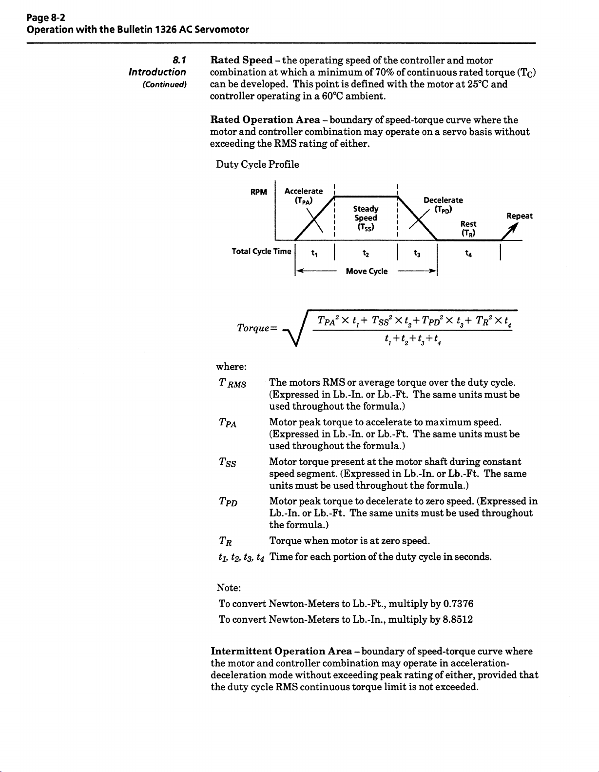
Page
8-2
Operation
with
the
Bulletin
1326
AC
Servomotor
8.
Introduction
(Continued)
be
Duty
Speed
developed.
operating
Operation
and
controller
the
Cycle
RPM
Cycle
Total
Torque
the
-
RMS
Profile
Accelerate
Time
operating
minimum
a
point
This
in
a
60°C
Area
-
combination
rating
OPA)
ti
TPA2
speed
defined
is
ambient.
boundary
either.
of
Steady
Speed
(Tss)
*2
Move
Xtt+
of
the
70%
of
with
speed-torque
of
operate
may
Cycle
Tss2
controller
of
continuous
the
on
Decelerate
ts
Tpo2
X
t2+
motor
a
servo
(TRD)
and
rated
at
curve
Rest
(TR)
X
t3+
motor
25°C
where
basis
t4
TR2
torque
and
the
without
/
X
t4
(Tc)
Repeat
1
Rated
combinationatwhich
can
controller
Rated
motor
exceeding
where:
T
RMS
TPA
Tss
Tpo
TR
ti,
Note:
convert
To
To
convert
The
(Expressed
used
Motor
(Expressed
used
Motor
speed
units
Motor
Lb.-In.orLb.-Ft.
the
Torque
,
1
Time
U
3
Newton-Meters
Newton-Meters
motors
throughout
peak
throughout
torque
segment.
must
peak
formula.)
when
each
for
RMS
in
torque
in
be
torque
average
or
Lb.-In.
Lb.-In.orLb.-Ft.
present
used
motor
portion
or
formula.)
the
to
accelerate
formula.)
the
at
(Expressed
throughout
to
decelerate
same
The
is
at
of
Lb.-Ft.,
to
Lb.-In.,
to
torque
Lb.-Ft.
The
to
The
the
motor
Lb.-In.orLb.-Ft.
in
the
to
units
speed.
zero
duty
the
multiply
multiply
over
same
maximum
same
shaft
formula.)
speed.
zero
must
be
cycle
in
by
0.7376
by
8.8512
duty
the
units
speed.
units
during
used
seconds.
cycle.
must
be
must
be
constant
The
same
(Expressed
throughout
in
Intermittent
motor
the
and
deceleration
cycle
duty
the
Operation
controller
mode
without
RMS
Area
combination
exceeding
continuous
boundary
-
torque
may
peak
limit
speed-torque
of
operate
rating
is
of
not
exceeded.
curve
acceleration-
in
either,
provided
where
that
Page 53

Operation
with
the
Bulletin
1326
AC
Servomotor
Page
8-3
Continuous
Torque
Stall
Lb.-ln./N-m Lb.-ln./N-m
93.3/10.53
102/11.5
140/15.8
153/17.3
210/23.7
310/35.0
420/47.4
420/47.4
All
©
Allen-Bradley.
Bulletin
48/5.4
ratings
(Tc)
are
for
1326AB
Introduction
Stall
Peak
(T
Torque
96/10.84
186.6/21.0
204/23.0
280/31.6
306/34.6
420/47.5
568/64.1
811/91.7
840/94.8
40°C
motor
Motor
8.
(Continued)
P)
ambient,
8.2
Options
1
Rated
Speed
RPM
3000
3000
3000
3000
3000
3000
3000
2000
1600
1
Table
selection
amplifier/motor
Bulletin
10°C
1391
Motor
1326AB-A3E
1326AB-B2E
1326AB-B2E
1326AB-B3E
1326A8-B3E
1
326AB-C2E
1326AB-C3E
326AB-C4C
1
1326AB-C4B
case
and
General
Shaft
Appendix
8.
contains
A
list
B/1326AB
Catalog
Number
amplifier
60°C
information
Oil
Seal
B
the
detailing
combinations.
Table
8.A
Controller
Catalog
1391B-AA15
1391B-AA15
1391B-AA22
1391B-AA22
1391B-AA45
1
391
1391B-AA45
391
1
1391B-AA45
ambient.
kit
are
motor
for
Bulletin
the
1326AB
performance
Performance
Servo
No.
B-AA45
B-AA45
on
the
presented
interconnection
Continuous
extended
For
Blower
Amperes
Data
Torque
7.8
16.4
16.4
24.6
24.6
33.2
49.1
45.6
38.2
mod
on
the
performance
parameters
at
Rotor
Lb.-ln.-Sec2/Kg-m2
(lc)
0.010/0.001
0.05/0.006
0.05/0.006
0.08/0.009
0.08/0.009
0.14/0.015
0.22/0.024
0.29/0.032
0.29/0.032
at
ratings
kit,
lower
Integral
following
information.
of
Inertia
ambients,
Holding
pages.
data.
selected
(JM)
consult
Refer
Included
Rated
Output
kW
1.2
2.28
2.5
3.5
3.8
5.2
7.5
7.0
5.6
Brake
to
is
and
a
Blower
The
Approved),
kit
Mod
consists
housing,
specifications
information.
SPECIFICATIONS
INPUT
VOLTAGE
AMPERES
LINE
CLEARANCE
INLET
AIR
IMPORTANT:
ENVIRONMENTS
THE
a
9.25
(235.0)
DIMENSIONS
(1326AB-MOD-G3)
Kit
impedance
of
an
grille
and
below
220/230V
0.15/0.14
(1
6"
BULLETIN
REQUIRING
1326AB-MOD-G3
t
6.75
(171.5)
i
INCHES
IN
ARE
guard
Figure
AC,
52.4)
65
IP
PROTECTION.
r
to
4.66
(118.4)
(MM)
AND
protected
necessary
and
for
8.2
HZ,
50/60
r
i-
«”)!
l(_l|
V-
fan
connection
1-PH.
OPTION
0.875”
0.5,”
CONDUIT
GA.
KIT
-i
AC
-*
_r
1.75(44.5)
(22.2MM)
12.7MM
STRANDED
(UL
recognized,
hardware.
and
dimension
MUST
NOT
VIEW
TOP
SERVOMOTOR
KNOCKOUT
DIA.
PROVISION)
BOX
2-18”(457.2MM)
WITH
FLYING
Refer
BE
USED
-4
LEADS
CSA
to
IN
SIDES.
INSIDE.
the
(WITH
18
Figure
8.2
Blower
-
Cooling
Option
Page 54

Page
8-4
Operation
with
the
Bulletin
1326
AC
Servomotor
Bulletin
1326AB
Motor
8.2
Options
(Continued)
Integral
The
Bulletin
when
the
-Kx
(24V
or
removal
limited
intended
BRAKE
AC
SERVOMOTOR
Watts
5
-
4
Up
to
-
DIMENSIONS
Holding
1326AB
motor
DC
power.
of
braking
continuously
to
be
COIL
Dissipation
Brakes
Motor
IN
ARE
Brake
catalog
input).
The
torque
per
115V
©
90V
®
INCHES
&
servomotor
number
The
brake
emergency
for
cycled
MOTOR
CONNECTOR
Motor
per
Module
AC
INPUT
OUTPUT
DC
(MM)
AND
DC
90V
contains
contains
brake
designed
is
I-*-
I
.*>•
0.165
is
a
to
assist
90V
1-125
(28.6)
j|®
MTG.
(4.19)
Power
an
a
suffix
type
disc
to
hold
stopping.
in
1326-MOD-BPS
DC
24V
H
®|
7
DIA.
HOLE
Supply
integral
of
that
load
a
However,
stopping
DC
90V
(ÿAx
ON
CATALOG
SUPPLY
DC
24V
DC
(-Kx
ON
CATALOG
1.125
(28.6)
I
(1326-MOD-BPS)
holding
(90V
-Ax
spring-set
is
at
BRAKE
MOTOR
NUMBER)
BRAKE
MOTOR
NUMBER)
rest
is
it
load.
a
_
FOR
-
FOR
0.250
TERMINAL,
DC
and
(6.35)
O
0.75
L*
(19.1)
I
H
brake
input)
upon
provide
not
115V
50/60
PLCS.
4
AC,
Hz
Shaft
Oil
Seal
Shaft
Oil
The
applications
splashes
Seal
where
(motor
IMPORTANT:
motor
the
The
Small
-
Bearing
-
1.
shaft
following
Hammer
Grease
Apply
minimize
a
IMPORTANT:
guard
against
motor
shaft.
Place
2.
the
installed
Slide
Using
the
seal.
casting.
the
the
3.
Figure
(1326AB-MOD-SSV)
Kit
the
mounted
This
partially
is
items
8.3
consists
motor
kit
will
Brake
-
to
is
be
shaft
gearbox,
a
not
fully
or
required
(8oz/0.23kg)
light
coating
possibility
the
cuttingorscraping
Any
over
seal
with
the
along
seal
small
seal
The
of
Use
care
damage
the
shaft
solid
the
hammer,
must
Viton
a
may
Supply
seal
be
etc.).
Power
of
intendedtobe
submerged
for
installation:
grease
of
when
seal
to
the
damage
placing
the
will
reduce
(see
Figure
shield
shaft
gently
be
installed
side
into
facing
position
tap
Connections
which
is
subjected
used
inside
surface
the
around
flush
to
applications
in
oil.
in
diameter
during
the
installation.
seal
in
effectivenessofthe
8.4).
The
motor
the
over
the
the
with
the
intended
occasional
for
oil
where
of
the
seal
shaft,
the
over
contact
seal
with
must
be
bearing.
end
bell
bore.
circumference
outsideofthe
use
to
the
seal.
of
in
to
Page 55

Bulletin
1326AB
Motor
8.2
Options
(Continued)
BEARING
Operation
with
1
the
Bulletin
IJ
1326
END
AC
BELL
SHAFT
(FINAL
CASTING
Page
8-5
Servomotor
SEAL
POSITION)
Motor
8.3
Maintenance
Bulletin
maintenance.
guard
the
1326AB
against
connector
Figure
brushless
The
coolantsorother
seals.
8.4
-
AC
connectors
Oil
Shaft
servomotors
shouldbemounted
materials
Seal
Installation
require
from
little
down,
coming
or
possible,
if
into
no
contact
to
with
Page 56

Page
8-6
Operation
with
the
Bulletin
1326
AC
Servomotor
This
-
Page
Intentionally
Left
Blank
-
Page 57

Chapter
9
Bulletin
Chapter
Transformers
1391
9.0
Objectives
9.1
Chapter9provides
the
Bulletin
information
provided.
The
Bulletin
three-phase,
a
Transformers
four
controllers.
are
available.
in
units
a
60°C
1391
including
1391
230V
supplied
The
ambient.
IMPORTANT:
Bulletin
1391
isl5kVA.
IMPORTANT:
35.5V
AC
transformer
is
recommended
Contact
different
a
connection
your
that
local
type
must
information.
Transformers
connection,
Isolation
must
AC
Standard
kVA
The
The
Allen-Bradley
Transformer.
operation
operate
output
with
the
three-phase
values
maximum
Bulletin
tap
to
a
Bulletin
be
used.
provide
dimension
and
external
from
and
a
Bulletin
specified
rating
1391
controller
power
Is
1391
Sales
to
Refer
and
Shunt
and
enclosure
In
addition,
resistor
isolation
an
single-phase,
can
1391
input
voltages
are
the
continuous
can
that
be
uses
to
the
)lation
Representative
Figure
Transformer
9.1
Regulators
information
regulator
shunt
dimensions
transformer
35.5V
provide
for
connectedtothe
phase
a
Logic
Control
if
Appendix
and
having
output.
AC
power
the
60
outputs
sensitive
be
used.
transformer
a
are
up
for
units
Hz
of
Board.
B
for
for
to
the
It
of
CAUTION:
center
A
HZ
60
Two
60
240/480V
1.
2.
208/230/460/575V
other
If
Allen-Bradley
local
connection
50/60
The
50/60
240/380/415/480V
Connections
dimensions
NEMA
Dimensions
connected
Transformers
transformers
Hz
AC
voltages
input
information
Transformers
HZ
transformer
Hz
to
the
provided
TYPE
for
1
the
Damage
tap
,
three-phase
Sales
AC,
50/60
(Y2,
wire
to
TB4-20
available
are
AC,
three-phase
special
or
Representative.
Figure
and
that
three-phase.
transformer
Hz
Figure
in
ENCLOSURE
NEMA
Type
to
the
Y5,
Y8,
as
shown
enclosures
9.2
available
is
9.2.
1
enclosures
controller
Yll)
in
and
have
are
Refer
for
dimensions.
has
are
shown
will
shown
Appendix
are
in
input
required,
Figure
to
input
an
in
shown
resultifthe
Figure
B.
ratings
Figure
consult
9.1
rating
Figure
in
of:
for
9.1
9.1
of
is
your
with
9.3.
not
IMPORTANT:
customer
assembly.
The
NEMA
Type
1
enclosure
shipped
is
as
for
a
kit
Page 58

Page
9-2
Transformers
and
Shunt
Regulators
JUMPER
FARADAY
SHIELD
G2
!Jt
Tr;
H3
H1
\
Y
G1
nnnnnnnnnn
xo
EARTH
GROUND
—
H2
\AAA<
H4
A
UJUJUUUU
X1
H6
V
AC*
230V
*
SECONDARY
H5
RATINGS
VA
H7
As
X2
4
<ÿ
—
AC*
230V
POWER
AS
BULLETIN
PRIMARY
VOLTAGE
AC
240V
480V
AC
H9
CONNECT
H1
TOH3TO
H2
TO
H4TOH6
H5TOH7TO
H2TOH3
H5TOH6
H8TOH9
H8
1391-TxxxDT
H8
H9
V
UJUU
JUUJ
pnrYYYVYÿnr
X3
4
PER
230V
WINDINGS
CHART
AC*
4
4
ill
LINES
HI
HI
P
1
Srv\
UY1
35.5V
CT200VA
H4
H4
Y2
Y3o
AC
ON
H7
H7
P2
CONNECT
SWITCH
THERMAL
PROTECTION
DC,
A/24V
1
m
|
(I
Y4
35.5V
CT200VA
<ÿ
(RATED
0.25A
Y5
Y6
AC
TO
GO
JUMPERGOTO
FOR
TRANSFORMER
AT
MIN.,1
rHH-i
n
OY7
WITH
115V
85°
35.5V
CT
C
1
200V
AC.
±5°Q
Y8
Y9n
AC
SEPARATE
A
WIRES
/T1!
*Y10
35.5V
CT200VA
<ÿ
.v.v.v.
I
Y11
Y12n
AC
-
G1
vX'X'XÿX'Xÿ'X'XvX'XvX'XvX'X'X'X’X
GO
A
FARADAY
SHIELD
wn
BULLETIN
PRIMARY
VOLTAGE
AC
240V
380V
AC
415V
AC
480V
AC
H1
•
rY~vnnnnnnnn
X0
=ÿ
-
H3
H2
•••••••••••••a
EARTH
GROUND
H4
X1
CONNECT
TO
H6
H2
H7TOH11
H12TO
H1
H3
TO
H6
H8TO
H11
H13TOH1
TO
H6
H4
H9TOH11
H14TOH1
H5TO
H6
H10TOH11
H15TOH1
H6
H5
230V
*
1391-TxxxET
LINES
H7
H8
H9
pnnrvvÿnnnr
X2
4
4
AC*
AC*
230V
SECONDARY
VA
RATINGS
POWER
AS
PER
ON
HI
H6
H11
H11
H10
AC*
230V
WINDINGS
CHART
H12
4
H13
X3
CONNECT
TO
H6
H2
H7TOH11
H12TOH1
TO
H3
H6
H8TO
H11
H13TOH1
H4
TO
H6
H9TO
H11
H14TOH1
HSTO
H6
H10TOH11
H15TOH1
P2
THERMAL
PROTECTION
1A/24V
Y2
Y3*
AC
1
391
Y4
CT200VA
<ÿ
-TxxxNT
SWITCH
DC,
0.25A
Y5
Y6#
AC
35.5V
->ÿ
LINES
FOR
(RATED
MIN.,
4Y7
ON
HI
H6
H11
JUMPER
GOTO
TRANSFORMER
115V
AT
AC.
185°C±5°
Y8
Y9
35.5V
AC
CT200VA
G1
C)
*Y10
<r
Y11
Y12||
35.5V
AC
CT200VA
G1
GO
BULLETIN
PRIMARY
VOLTAGE
AC
208V
AC
240V
AC
480V
575V
AC
H15
H14
4
P1
Y1
#
35.5V
CT200VA
<-
Figure
9.1
Bulletin
-
1391
Transformer
Wiring
Diagrams
Page 59

Transformers
and
Shunt
Page
9-3
Regulators
Catalog
1391-T015DT
1391-T015ET/NT
1391-T025DT
1391-T025ET
1391-T035DT
1391-T035NT
1391-T050DT
1391-T050ET/NT
1391-T100DT
1391-T100ET/NT
1391-T125DT
1391-T125ET/NT
1391-T150DT
1391-T150ET/NT
Number
n
I
APPROXIMATE
kVA
1.5
2.5
3.5
5.0
10.0
12.5
15.0
A
(228)
9.00
(228)
9.00
11.00(279)
11.00(279)
11.00(279)
11.00(279)
(279)
11.00
(279)
11.00
(305)
12.00
(305)
12.00
(305)
12.00
(305)
12.00
(330)
13.00
13.00(330)
i
DIMENSIONS
(MILLIMETERS)
INCHES
IN
B
10.00
10.00
11.00(279)
1
.00
1
11.00
11.00
11.00
11.00(279)
12.50(317)
12.50(317)
12.50(317)
12.50(317)
14.00
14.00(356)
(254)
(254)
(279)
(279)
(279)
(279)
(356)
AND
WEIGHT-
POUNDS
AND
C
13.00(330)
13.00(330)
14.00(356)
14.00(356)
14.00(356)
14,00(356)
14.00(356)
14,00(356)
16.00
16,00(406)
16.00
16.00(406)
17.50(444)
17.50(444)
0.22R
(5.6)
ISOLATION
(KILOGRAMS)
(406)
(406)
Slot
TRANSFORMER
D
5.00(127)
5.00(127)
6.00(152)
6,00(152)
6.00(152)
6.00(152)
6.00(152)
6,00(152)
(203)
8.00
(203)
8.00
(203)
8.00
(203)
8.00
9.50(241)
9.50(241)
1
i
0.53
(13.5)
E
3.10(79)
(89)
3.50
(84)
3.30
4.00(102)
4.50(114)
4.50(114)
5.25(133)
6,00(152)
5.85(149)
5.85(149)
5.63(143)
(143)
5.63
6.00(152)
6.00(152)
r
Weight
27(12.2)
40(18.2)
42(19.0)
(27.2)
60
(27.2)
60
(38.6)
85
(34.0)
75
100(45.4)
112(50.8)
140(63.6)
126(57.1)
(72.7)
160
(68.0)
150
(90.9)
200
B
Max.
Catalog
1391-TA2
Number
D
CMax.
APPROXIMATE
kVA
All
17.00(432)
u
Figure
9.2
-
DIMENSIONS
(MILLIMETERS)
INCHES
IN
A
B
Front
0.44
Isolation
AND
B
19.00(483)
Ref.
(112)
Transformer
WEIGHT
AND
POUNDS
14.50(368)
n
m
A
Dimensions
-NEMA
(KILOGRAMS)
C
T
TYPE
16.50(419)
<-
y
1
ENCLOSURE
D
C
Side
E
Max.
A
E
12.00(305)
->ÿ
L
'i
Weight
35.5(16.1)
i:
Figure
D
9.3
NEMA
-
Type
Enclosure
1
r
Dimensions
“i
E
Page 60

Page
9-4
Transformers
and
Shunt
Regulators
Shunt
Regulator
9.2
Operation
section
to
Refer
The
nominal
Overvoltage
DC
Bus
Bus
DC
Nominal
Bus
DC
The
shunt
timer.
selector
average
reached,
action
The
would
Duty
terminal
designated
higher
The
resistor.
data
Trip
Shunt
Shunt
DC
Undervoltage
regulator
The
timer
switch
power
the
controller
be
Cycle
Block,
to
“0
the
Duty
The
controller/shunt
IMPORTANT:
dentonthe
shunt
4.4
for
an
the
shunt
explanation
for
Point
Point
“ON”
“OFF”
Bus
Point
Voltage
Detect
behaviorismodified
usedtomodel
is
(SW1)
determines
levelatwhich
will
equivalent
Selector
TB5
F,”
setting,
(see
with
Cycle
Switch
Figure
“0”
the
Selector
combinations
Accurate
resistor
operation
value.
regulator
the
be
forced
turning
to
being
higher
are
of
405V
=
386.4V
=
366.9V
=
300V
=
145V
=
the
shunt
temperature
the
controller
to
the
is
located
10.2).
the
average
the
Switch
shown
of
Do
Not
the
provided
is
DC
±2.5%
DC
DC
DC
DC
±
by
resistor
will
fault
shunt
on
The
switch
lowest
settings
in
Tables
Duty
the
substitute
shunt
20%
adjustable
an
fault.
on
an
regulator
top
of
value
power
Cycle
regulator
below.
duty
temperature.
level
and
When
overvoltage.
off.
the
controller
and
seen
the
9.A
positions
16
“F”
various
and
by
has
for
Timer
alternate
circuitry.
cycle
therefore
this
level
This
near
highest.
the
the
shunt
B.
depen¬
is
values.
A
the
is
Table
resistor
external
available
Configuration
1391-AA15
resistor
1391-AA22
resistor
1391-AA22
resistor
1391-AA45
resistor
*
Denotes
1391-NIOD-SR22A.
A
9.
power
resistor
for
(Catalog#
SW1
provides
the
with
with
with9ohm
with
setting
CAUTION:
configurations
A
result.
required
the
trip
points
assembly
22.5A
for
Bulletin
Maximum
Factory
for
standard16ohm
standard12ohm
external
-MOD-SR22A)
1391
standard
ohm
5
of
time
at
The
factory
(catalog
Switch
Supplied
internal
internal
shunt
external
shipment.
designated
must
Duty
supplied
number
1391.
Table
Settings
User
be used
Cycle
Selector
configurations.
1391-MOD-SR22A)
9.A
Trip
and
Configurations
SW1
Switch
Setting
B*
B*
F
D*
must
reconfigure
settings
damage
or
for
Switch
Points
controller
the
to
the
settings
An
Nominal
(in
watts,
for
factory
controller
is
Trip
Point
10%)
±
164
162
386
715
use
supplied
may
and
with
Table
9.B
various
setting,
Overvoltage
an
shows
switch
the
excess
the
nominal
settings.
power
Fault
resistor
When
will
cause
condition.
shunt
power
requirements
the
bus
trip
voltage
levels
exceed
to
in
rise,
watts
the
resulting
for
the
selector
in
Page 61

Shunt
Regulator
9.2
Operation
(Continued)
SW1
Switch
Setting
*
Denotes
Page
9-5
Shunt
22.5A
with
9
Ohm
103
109
115
122
130
139
150
163
177
195
216
243
277
323
386*
supplied
and
Data
External
Resistor
98
configurations.
Transformers
9.B
Table
Trip
Level
Watts,
factory
for
Reference
10%)
±
Nominal
15A
with
Internal
Ohm
Resistor
16
0
1
2
3
4
5
6
7
8
9
A
B
C
D
E
F
the
67
71
75
80
85
91
99
107
118
130
145
164*
maximum
Power
(Continuous
allowable
with
Ohm
12
settings
22.5A
Internal
Resistor
73
77
82
86
92
98
105
113
122
133
146
162*
Regulators
45A
with
External
Ohm
Resistor
5
215
227
241
256
274
294
317
344
378
417
466
527
607
715*
872
1115
WARNING:
equipment
A
designated
resistor
Duty
properly
WARNING:
shunt
A
(SW1)
assembly.
appropriate
result
overheated
Frequent
the
indication
dissipation
Allen-Bradley
value
motor
for
overvoltage
inertia)
that
capacity
the
configurations
Cycle
before
resistor
mustbeset
personal
in
during
external
an
is
specify
will
controller
guard
To
damage
cycle
duty
Selector
operation.
When
assembly,
Consult
derating
resistor.
trips
on
regenerative
shunt
required.
shunt
a
being
against
from
settings
must
Switch
using
to
an
the
resistor
guidelines.
injury
high
resistor
Based
resistor
used.
personal
overheated
an
for
not
be
(SW1)
customer
a
Duty
the
appropriate
manufacturer
and/or
inertia
equipment
systems
states
having
the
on
with
injury
resistor,
factory
supplied
exceeded.
to
ensure
supplied
Cycle
Selector
for
level
Failure
(deceleration)
to
(load
increased
supplied,
data
proper
the
and/or
the
Check
that
external
that
for
comply
damage
2
is
may
power
resistance
shunt
the
set
is
it
Switch
resistor
the
could
from
times
or
3
be
an
an
Page 62

Page
9-6
Transformers
and
Shunt
Regulators
Shunt
Regulator
9.3
Installation
EXTERNAL
The
Bulletin
resistor
the
block
The
22.
to
the
on
22.5A
units,
TB5.
following
controllers
5A
the
resistor
Interconnect
A
Remove
1.
TB5.
This
regulator
shunt
A
SHUNT
22.5
the
steps
for
and
Diagram
designed
is
and
user
provide
use
fuse
1391
the
WARNING:
ensure
to
terminal
and
WARNING:
assembly
internal
above
damage
internal
that
performing
9
discard
disconnects
circuit.
with
resistor
instructions.
could
resistor
RESISTORS
to
45A
units.
reconfigure
must
the
information
with
an
mounting
Appendix
in
guard
To
power
all
following
the
)
(
-I-
the
and
jumper
the
internal
When
the
assembly
result
is
7(
using
22.5A
Personal
from
not
the
use
B,
as
controller
procedure
of
TB5
shunt
an
external
Bulletin
has
injury
an
overheated
use
an
the
shunt
an
between
been
allow
To
external
dimensions
against
to
the
)
—
present
disconnected.
of
an
external
controller
needed
resistor
provided
required.
electrical
has
and
measures
resistor
shunt
1391,
disconnected
and/or
external
to
been
the
0.00
terminals8and
and
ensure
resistor
shunt
shunt
resistor
terminal
at
properly
and
fuse.
Figure
in
shock
removed
voltage
bus
volts.
fuse
from
resistor
that
per
equipment
if
convert
9.4
hazard,
the
the
the
with
Refer
and
prior
at
10
the
of
Connect
2.
Connect
IMPORTANT:
the
with
Fusing'
Connect
3.
Using
4.
setting
for
Table
for
A
5.
Install
the
endofthe
one
the
shunt
the
the
WARNING:
manufacturers
these
manufacturer
could
from
appropriate
end
other
The
resistor.
more
information.
remaining
9.B,
set
resistor
in
external
result
overheated
an
the
external
new
of
the
external
Refer
endofthe
Duty
being
Proper
nominal
shunt
recommended
for
personal
in
shunt
shunt
to
fuse
resistor.
one
shunt
resistor
paragraph
to
the
shunt
Cycle
Selector
used.
derating
resistor
configurations.
injury
in
fuse
its
fuse
of
end
resistor
must
power
derating.
and/or
holder.
to
terminal
shunt
the
have
must
entitled
to
terminal
Switch
applied
be
ratings
Consult
Failure
equipment
to
the
of
9
resistor.
fuse
a
“Shunt
8
appropriate
to
the
when
the
resistor
to
damage
TB5.
in
series
TB5.
of
using
comply
Page 63

Transformers
and
Shunt
Page
9-7
Regulators
Shunt
Regulator
(5.2)
0.203
(8.7)DIA.C.B.
0.343
9.3
Installation
(Continued)
DIA.
w/
SHUNT
Shunt
controllers.
resistor
controller
resistors
must
dimensions).
IMPORTANT:
the
regulator
be
shunt
FUSING
The
against
near
22.5A
for
mounted
Controller
fuse
fusing
fuse
is
circuits.
short
the
circuit
and
externaltothe
Table
to
Refer
15A
22.5A
22.5A
45A
Repeated
has
malfunctioned.
provided
is
series
in
breaker
controllers
45A
9.C
Shunt
Fuse
Top
Top
External
External
overvoltage
with
with
The
shunt
for
controller
for
further
Table
Fuse
Location
Panel
Panel
of
all
the
the
resistor
is
fuse
22.5A
and
15
supplied
are
(see
shunt
9.C
Information
Type
Fuse
Buss
KLM-10
FNM-6.25
Buss
KTK-1
Buss
Buss
KLM-20
tripping
Bulletin
and
located
controllers.
with
Figure
fuse
equivalent
or
or
equivalent
5
or
equivalent
or
can
be
1391
protect
to
used
top
on
9.4
information.
equivalent
an
of
External
which
fuse
a
mounting
for
indication
the
the
that
2.81
(71.4)
H
0.16
(4.1)
Li
o
u
r
b
"ÿ(3
o
I
7“1
i
!
A0)
Figure
(7.1)
0.281
0.562(14.2)
I
2.25
(57.1)
t
9.4-
nn£
)
4
x
\
~r\
1.13
CD
(28.7)
Y
Approximate
LS
Uk
O
Dimensions,
DimensionsinInches
12.75
(323.8)
14.00
(355.6)
External
Shunt
(mm)
and
Resistor
and
JL
Fuse
jr
jrm
5.38
(136.6)
1.87
(47.5)
JL
CD
o
Page 64

Page
9-8
Transformers
and
Shunt
Regulators
-
This
Page
Intentionally
Left
Blank
-
Page 65
Chapter
10
Troubleshooting
System
Chapter
Objectives
Troubleshooting
10.0
10.1
Chapter
Bulletin
10
1391.
diagnosis,
Most
controller
on
the
front
themselves
identifying
in
aid
Table
10.A
addition,
Tables
potential
10.B
servomotor
10.D
Table
points.
A
provides
information
Includedinthe
general
system
faults
of
the
controller.
through
a
servo
provides
a
causes
and
10.C
malfunctions
provides
a
WARNING:
To
avoid
hazardofelectrical
the
capacitors
service,
Voltage
repair
at
measured
Only
qualified
equipment
should
attempt
to
chapter
troubleshooting
are
annunciated
Many
controller
controller
listing
provide
and
listing
This
terminals
are
has
or
fault.
and
description
and
listed.
number
a
their
description
and
product
been
remove
(
9
possible
discharged
withastandard
personnel
and
safety
proceduresinpublication
procedure.
this
guide
are
by
system
The
motor
of
contains
shock,
this
)
and
+
digital
familiar
user
the
LED
and
the
LED
malfunctions
use
troubleshooting
in
descriptions
point
test
diagnostic
LED
indications
of
descriptions.
manifest
malfunctions.
the
of
common
LED
system
indicators.
and
causes.
of
the
Bulletin
stored
verify
before
that
attempting
1391
energy
all
unit.
(-)
of
7
TB5
must
be
voltmeterormultimeter.
with
solid-state
NFPA
and
fault
indicators
may
test
devices.
voltage
to
“0.00”
control
70E
the
In
on
as
LED
OVER¬
TEMPERATURE
(RED)
POWER
(RED)
FAULT
Description
LED
The
controller
thermal
which
transistor
temperature
LED
The
output
If
level
controller
illuminate.
will
current
the
senses
current
(greater
switchonthe
illuminate.
transistors
contains
power
the
temperature.
is
exceeded
through
is
exceeds
300%
than
rating)
the
Descriptions
LED
a
heat
sink
If
the
the
power
the
monitored.
fixed
a
of
will
LED
Table
10A
Fault
(±
input
thermal
of
the
ambient
duty
controller.
fan
access
LED
through
winding
Diagnosis
Cause
LED
2V
1
atTB4-19,
following
cycle
is
not
to
is
current
powertransistor.
to
and
Condition
OVERTEMPERATURE
The
etc)
The
One
.
1
2.
3.
4.
POWER
.
1
2.
3.
4.
/
Potential
supply
logic
AC
or
the
heat
sink
or
more
The
cabinet
The
machine
rating
of
the
integral
The
airflow
The
FAULT
current
The
of
the
controller's
Malfunctioning
Shorted
Excessive
load.
is
Illuminated
DC,
overload
the
Illuminated
any
case
DC)
5V
+
20,
has
may
temperature
requires
functioning.
controllerislimited
one
of
rating.
motor
circuits
incorrectly
is
21
tripped.
have
occurred
too
is
RMS
an
power
the
capacitance.
have
:
high.
current
or
transistors
malfunctioned
wired.
exceeding
blocked.
has
the
exceeded
(fuse
blown
continuous
300%
Page 66
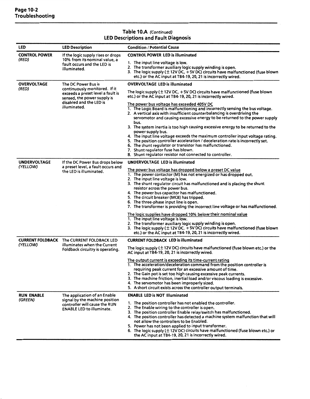
Page
10-2
Troubleshooting
LED
CONTROL
(RED)
POWER
OVERVOLTAGE
(RED)
UNDERVOLTAGE
(YELLOW)
CURRENT
(YELLOW)
RUN
(GREEN)
FOLDBACK
ENABLE
Description
LEO
logic
If
the
10%
from
occurs
fault
illuminated.
DC
The
Power
continuously
exceeds
sensed,
disabled
a
the
and
illuminated.
If
DC
Power
the
level,
preset
a
the
The
is
LED
CURRENT
illuminates
Foldback
The
signal
circuitry
application
by
the
controller
ENABLE
LED
supply
rises
nominal
its
and
the
Bus
is
monitored.
preset
levelafault
power
supply
LED
the
Bus
fault
a
illuminated.
FOLDBACK
the
when
is
of
an
machine
cause
will
to
illuminate.
LED
drops
or
value,
LED
is
If
is
is
drops
occurs
LED
Current
operatinq.
Enable
position
RUN
the
Table
Descriptions
Condition
CONTROL
a
1.
2.
3.
OVERVOLTAGE
it
The
is
etc.)
The
1.
2.
3.
4.
5.
6.
7.
8.
below
UNDERVOLTAGE
and
The
.
1
2.
3.
4.
5.
6.
7.
The
1.
2.
3.
CURRENT
...
The
AC
The
1.
2.
3.
4.
5.
ENABLE
1.
2.
3.
4.
5.
6.
(Continued)
10.A
Fault
voltage
input
AC
LED
(±
input
voltage
with
and
LED
(±
12V
is
causing
Diagnosis
Cause
auxiliary
is
at
malfunctioning
and
/
Potential
POWER
input
The
The
transformer
logic
The
etc.)
or
the
logic
supply
or
AC
the
power
bus
The
Logic
A
vertical
servomotor
line
supply
Board
axis
bus.
system
The
power
The
The
The
Shunt
Shunt
supply
input
position
shunt
regulator
regulator
line
regulator
inertia
bus.
voltage
controller
fuse
resistor
is
LED
power
The
The
The
resistor
The
The
The
The
logic
The
The
The
etc.)
lo9lc
input
output
The
requiring
The
The
The
A
short
The
The
The
The
not
Power
The
AC
the
voltage
bus
power
contactor
input
line
voltage
regulator
shunt
across
power
circuit
three-phase
transformer
supplies
input
line
transformer
logic
supply
or
the
FOLDBACK
supply
TB4-19,
at
current
the
capacitor
bus
breaker
have
voltage
input
AC
,,
,
(±
12V
power
input
is
providing
auxiliary
(±
LED
20,
exceeding
is
acceleration/deceleration
peak
current
pot
Gain
machine
servomotor
LED
position
Enable
position
position
allow
has
logic
circuit
is
the
not
supply
input
set
is
friction,
has
exists
NOT
controller
wiring
controller
controller
controllers
been
(±
atTB4-19,
too
Illuminated
to
is
illuminated
low.
is
logic
supply
winding
12V
at
DC,
TB4-19,
+5V
20,
DC)
21
circuits
is
illuminated
DC,
TB4-
has
DC)
+5V
20,
9,
1
exceeded
circuits
21
405V
is
incorrectly
and
insufficient
too
exceeds
counterbalancing
excessive
high
causing
the
energy
excessive
maximum
acceleration/deceleration
or
transistor
blown.
has
not
illuminated
is
dropped
has
(M)
has
is
low.
circuit
bus.
has
(MCB)
line
dropped
low.
is
DC,
12V
at
TB4-1
is
illuminated
,
.
DC)
circuits
incorrectly
is
21
for
high
inertial
been
across
has
the
controller
Enable
has
to
applied
DC)
12V
20,
connectedtocontroller.
has
has
open.
is
logic
+
9,
an
causing
improperly
the
not
detected
be
to
circuits
21
malfunctioned.
has
below
energized
not
malfunctioned
malfunctioned.
tripped.
the
incorrect
10%
below
winding
supply
DC)
5V
circuits
20,
21
is
.
.
malfunctioned
have
wired.
its
time-current
command
excessive
excessive
load
and/or
sized.
controller
enabled
isopen.
relay/switch
a
machine
Enabled.
input
transformer.
have
incorrectly
is
isopen.
have
incorrectly
have
malfunctioned
wired.
DC
incorrectly
to
be
returned
sensing
is
energy
controller
preset
line
their
or
and
voltage
DC
has
nominal
isopen.
a
have
incorrectly
,,
rating
from
the
viscous
output
the
controller.
has
of
peak
loading
terminals.
malfunctioned.
system
amount
malfunctioned
wired.
malfunctioned
wired.
(fuse
the
bus
overdriving
the
to
be
to
returned
input
voltage
incorrectly
rate
is
value
dropped
is
placing
or
has
out.
the
malfunctioned.
value
malfunctioned
wired.
,,
.
(fuse
blown
position
controller
time.
currents.
is
excessive.
malfunction
(fuse
blown
(fuse
voltage.
the
power
shunt
(fuse
etc.)
blown
blown
supply
to
rating.
set.
blown
or
is
that
etc.)
the
the
will
or
Page 67

Descriptions
LED
Table
10.A
(Continued)
and
Fault
Diagnosis
Page
10-3
Troubleshooting
LED
RUN
ENABLE
(Continued)
DRIVE
READY
(GREEN)
Condition
System
or
Axis
System
or
Axis
Desired
motor
deceleration
does
Motor
Velocity
Presence
Tach
Command
of
signal
runs
is
unstable
acceleration
cannot
respond
not
on
noise
wires
Description
LED
This
ed
uncontrollably
be
LED
until
/
obtained
a
to
is
a
Command
continuously
system
fault
Possible
1.
2.
1
2.
3.
1
2.
3.
4.
5.
1.
2.
3.
4.
5.
6.
7.
8.
9.
or
1
2.
3.
4.
5.
illuminat-
occurs.
General
Cause
velocity
The
incorrect
internal
An
Velocity
.
Position
Improper
position
Current
.
The
Current
The
system
The
system
The
Available
The
controller
The
controller
power
The
Power
motor
The
motor
The
The
motor
motor
The
The
feedback
.
60
Hz
20
1
Hz
or
180
Variable
disturbance
motor
the
Recommended
Condition
ENABLE
1.
2.
3.
4.
The
1.
2.
3.
DRIVE
1.
System
feedback,
open.
or
controller
Compensation
Loop
Loop
Gain
grounding
feedback
Limit
Feedback
inertia
friction
controller
is
contactorisnot
transformer
wi
ri
or
transformer
has
coupling
circuit
frequency
line
from
360
Hz
frequency
power
single
a
from
caused
/
Potential
LED
is
A
controller
indicators.
component
A
The
circuit
power
The
controller
supply
logic
The
supply
Logic
A
controller
indicators
System
Table
(check
READY
fault
10.B
Troubleshooting
position
malfunction
or
Position
shielding
or
velocity
or
incorrectly
pot
is
Scaling
is
excessive.
torque
is
current
a
malfunction.
has
not
enabled.
energized.
supplying
is
open.
ng
is
malfunctioned.
transmission
grounding
thermal
malfunctioned.
has
(motor
may
be
phase
logic
adjustable
other
(varies
with
by
gearteeth
per
Cause
Illuminated,
malfunction
Check
the
malfunction
(MCB)
breaker
contactor
supplies
logic
fuses
voltage
AC
malfunction
the
LED
NOT
is
has
occurred.
feedback
exists.
Gain
or
Controller
techniques
command
set.
is
incorrect.
excessive.
insufficient
is
incorrect
the
overload
controller)
to
present.
supply
motor
or
components
Appendix
Controller
but
occurred
has
status
of
exists
tripped.
is
has
been
not
are
not
are
blown
is
missing
has
occurred
of
status
illuminated
device
potentiometer
accel/decel
are
lines,
causing
supply
to
voltage
has
open.
is
may
be
speed
drives
may
speed)
ballscrew
B
balls
or
has
ballscrew
the
Drive
in
energized
operational
the
Drive
velocity
or
causing
the
tripped.
present.
maybe
be
etc.
not
been
does
but
OK
the
Enable
but
OK
incorrectly
is
is
rate
noise
erratic
correct
none
or
present.
velocity
The
speeds.
followed.
not
Enable
is
annunciatedbythe
not
(DROK)
output
circuit.
or
has
malfunctioned.
not
is
annunciated
contacts).
command
set.
improperly
to
be
axis
movement.
accel/decel
all.
at
transmitted
feedback
frequency
signal
set.
ripple
maybe
relay.
wiring
rate.
by
or
a
multiple
a
the
into
LED
LED
is
the
of
Page 68

Page
10-4
Troubleshooting
Condition
Rotation
No
Overheating
Abnormal
Erratic
position,
with
Noise
Operation
runs
reduced
without
torque
Motor
-
locks
control
into
or
General
Possible
.
1
The
Foreign
2.
3.
The
4.
The
5.
The
.
1
The
2.
Motor
3.
The
.
1
Loose
2.
Through
3.
The
GAIN
4.
.
1
Phases
Sine,
2.
Sine,
3.
Combinations
4.
Table
Servomotor
Cause
motor
connections
matter
motor
bearings
brake
rotor
voltage
duty
cycle
parts
bolts
bearings
setting
A&B.A&CorB&C
Cosine
Cosine,
load
are
is
set
partially
is
are
are
is
or
Rotor
lodged
is
is
excessive.
worn.
(when
is
exceeding
is
excessive.
present
are
loose.
worn.
high.
too
Rotor
lead
1,2,3
of
10.C
Troubleshooting
loose
the
in
the
the
motor.
reversed
reversed
reversed
or
motor.
maximum
are
equipped).
demagnetized
in
leads
sets
open.
causing
excessive
value.
motor
current.
Test
Point
TP1
TP3
TP4
TP5
TP6
TP7
TP8
TP9
TP10
TP11
TP12
TP13
TP14
TP15
TP
16
TP17
TP18
19
TP
TP20
TP21
TP22
TP23-TP24
TP26-TP27
TP28
TP29
TP30
TP31
Point
Test
Description
Buffered
Tachometer
Demodulated
Demodulated
]D_
PWM
Triangle
PWM
B
PWM
A
PWM
C
PWM
MultiplierTriangle
Signal
Common
12VDC
+
DC
-12V
Reference
lB
Reference
lA
|l|
Absolute
Velocity
Buffered
Velocity
Current
Current
Velocity
Velocity
Signal
Common
Current
Current
Signal
Common
Descriptions
Resolver
Output
Sine
Cosine
(2.5
Value
Gain
Calibration
Velocity
Error
Limit
Command
Loop
Loop
Feedback
Feedback
Command
Calibration
Response
Response
(Phase
(Phase
10.2
Signal
Rotor
(2.5V/kRPM)
Wave
Wave
kHz,
1Vp-p)
1
(22.5
(adjust
Calibration
Calibration
B,
A,
2.5V
2.5V
Table
1391
kHz,
with
p-p=
p-p
10.D
controller.
Test
p-p)
15V
R148,
Rated
Rated
=
describes
Table
Point
3V=
Rated
Motor
Motor
the
to
Refer
10.D
Descriptions
Current)
Motor
Current)
Current)
various
Figure
test
10.1
points
test
for
foundinthe
point
locations.
Bulletin
Page 69

Page
10-5
Troubleshooting
CURRENT
SCALING
FEEDBACK
SWITCH
TP1
0
TERMINAL
RESOLVER
-
0000000000
TP1
TP2
LOGIC
BULLETIN
CONTROL
TPS
1
1391
3
TP
IS
P2
1
P3
TP30
1
TP29
n
TP16
S1
BLOCK
TB1
BOARD
S
PI
TP5
TP8
TP9
TP10
TP13
TPM
TP15
R1
TB1
SIGNALS
10
TP4
TP7
TP12
f
-
OFFSET
SCALE
GAIN
R132
E3
a
Figure
TP18,
19
1=1
PS
TP20
O
g]
P13
R144
P6
T
p7
I
P10
TP22
1
00000000000000
TERMINAL
I/O
-
Logic
10.1
-
R148
Q
I
TP21
B
P9
TB2
BLOCK
SIGNALS
Control
TP17
TB2
-
s
P4
14
TERMINAL
Board
(H
E
P11
1
0000
-NOT
Test
DS1
DS3
DS4
0S5
DS6
DS7
DS8
TB3
USED-
Point
4
BLOCK
Locations
TB3
IS
P8
OVERTEMPERATURE
FAULT
POWER
CONTROL
OVERVOLTAGE
UNDERVOLTAGE
CURRENT
RUN
DRIVE
ADJUSTABLE
CURRENT
UMIT
POWER
FOLDBACK
ENABLE
READY
(R)
(R)
(R)
(R)
(Y)
(Y)
(G)
(G)
Page 70

Page
10-6
Troubleshooting
©
F3
15A
22.5A
PROVIDED
KLM-10
FNQ
6
GROUND
ON
15
AND
1
SERI
/4
STUD
22.5A
ESBONLY
UNITS
ONLY.
1
TB4
TB5
10
22
a*
F3
SW1
1
11
©
F1
MCB
F2
TB1
1
10
Figure
10.2
Bulletin
-
1391
Top
Panel
Page 71

Appendix
A
Dimensions
are
o*
AC
Inches
in
SERVO
(mm)
and
d
ALLEN-BRADLEY
CONTROLLER
SEE
17.50
(444.5)
DETAIL
18.40
(467.4)
A
(482.6)
a
19.00
Controller
6.00
(152.4)
5.20
(132.1)
Dimensions
3.70
„
(93.9)
Vl
NOTES:
j\J
(6.3)
0.25
0.30(7.6)
1.
MOUNTING
A
MINIMUM
2.
SEE
DETAIL
4.50
(114.3)
6.20
(157.5)
1
-M
t
SLOTS
SPACING
J
4
B
LA
H
f
AND
A
DETAIL
KEYHOLE
0.312"
OF
A
0.67(17.0)
(21.6)
0.85
0.312
0.60(15.2)
WILL
(7.9MM)
(7.9)
DIA
DIA
ACCEPT
REQUIRED
IS
1/4-20
0.39
(7MM)
HARDWARE.
BETWEEN
±
J
(9.9)
ADJACENT
9.10
(228.6)
10.64
(270.2)
DETAIL
B
z
CONTROLLERS.
0.312
(25.4MM)
1"
(7.9)
DIA
IS
RECOMMENDED.
Page 72

A-
Page
2
Controller
Dimensions
Page
This
-
Intentionally
Left
Blank
-
!
Page 73

Appendix
B
Interconnect
Bulletin
Interconnect
Drawings
1391
Drawing
AppendixBprovides
wiring
position
possible,
The
diagrams
Bulletin
-
between
control
these
recommended
Bulletin
-
Bulletin
-
Bulletin
-
Bulletin
-
Bulletin
-
the
products.
diagrams
provided
1391
1391
1391
1391
1391
1391
interconnect
control
IMC
/
/
IMC
/
8400
/
8600
/
Creonics
Drawing
The
Bulletin
B-3.
and
NOTES:
1)
Refer
POWER
15A
22.5A
45A
WIRING
1391
to
AWG
12
AWG
10
AWG
8
the
Interconnect
UNLESS
typical
Bulletin
are
include:
circuitry.
120
123
Series
Series
“Notes”
75C
MIN.
75C
MIN.
75C
MIN.
interconnection
and
1391
Due
to
the
provided
drawing
Interconnect
Interconnect
CNC
CNC
MAX4
and
Drawing
listed
NOTED:
MIN.
MIN.
MIN.
Interconnect
diagrams
various
numerous
for
showing
Interconnect
Interconnect
MAX/CONTROL
below
other
reference
Drawing
Drawing
presented
is
when
electrical
the
that
Allen-Bradley
only.
inputs,
Drawing
Drawing
Interconnect
pages
on
using
this
Drawings
illustrate
circuit
designs
outputs
B-2
drawing.
the
and
2)
SIGNAL
3)
4)
5)
6)
7)
8)
9)
WIRING:
ALLEN-BRADLEY
AWG
8
AWG
2
1
RESOLVER
RESOLVER
TERMINATE
DO
NOT
PROVIDED
F3
ONLY.
INSERTED
P1
CURRENT
18
SUPPLIED
MOTOR
MOTOR
CABLE:
SHIELD
CONNECTIONS
MAKE
15
ON
1.5V/KRPM,
FOR
FEEDBACK
AWG
MIN.
CABLE:
326-CPCxx
1
1
326-CPABxx
326-CFUxx
1
1
326-CFUxx
SOURCE
ON
&
22.5A
SCALING:
END
TO
UNITS
P1
REMOVED
SEE
ONLY.
UNUSED
ONLY.
SECTION
PINS
15A
FOR
5.3.
ON
THE
KLM-10,
=
2.5V/KRPM.
RESOLVER
22.5A=FNQ
CONNECTOR.
6V4
SERIES
B
Page 74

Page
B-2
Bulletin
1391
Interconnect
Drawings
EXTERNAL
CURRENT
(IF
SUPPLIED
CONTROLLER
MOTION
(Volts)
12-120
220-240
380480
500-600
LIMIT
USED)
CNC
BY
ACII
Ue
"M”
Ratings
OR
OR
CONTACT
le
(Amps)
6
3
1.5
1.2
VELOCITY
TORQUE
COMMAND
10K
1/2W
MINIMUM
RUN
'-0ÿ0
RATINGS
Ratings
DCII
Ue
(Volts)
28
110
220
440
660
TACH
(NOTE
CMD
1
TB4-15
PWR.COM.
LOW
le
(Amps)
5.0
1.25
0.62
0.27
0.20
NOTE
5
OUTPUT
8)
OUTPUT
n*
u
TB4-16
RESET
BUS
TB4
TB4
TB4
TB4
TB4
TB4
TB4
TB4
TB4
.
TB2r-H
I
TB2H;
t
l
\
TB2fJ-
•-
TB'2U
TB2[5]
TB2[S
TB2[J\
TB2[s
TB2
TB2
TB2nT
TB2
TB2[i3}
m
I
J-M
ra
fl
-LM
1
115VAC
IAMP
±
DR
(CLOSED
ra
SPARE
[§
-REF
dh_r>
4
SHIELD
3
4.99K
a
(5.0VDC
INPUT
(
/-2.5VDC/KRPM
+
(
/-1.5VDC/KRPM
+
V
(+/-3.0VDC
9
©-
ENABLE
io|
(MOMENTARILY
V
OK
I2VDC
t
=
t
INPUT
OK)
=
200%
=
-
-
RATED
ENABLE
GND
DSl(
DS2
DS3(
DS4
DS5
DS6
DS7
DS8
l-LIMIT)
OUT)
P1
IN)
P1
MOTOR
TO
![R)DRIVE
POWER
3[RJC0NTR0L
BUS
BUS
%
CURRENT
GRUN
G
DRIVE
CURRENT)
SOURCE
RESET)
TYPICAL
GROUND
LUG
OVERTEMP
FAULT
POWER
OVERVOLTAGE
UNDERVOLTAGE
FOLDBACK
ENABLE
READY
CURRENT
SCALING
CHASSIS
WALL
BUS
SUPPLY-
(230VAC)
si
&
7
*
3
8
FEEDBACK
(NOTE
RI32
SCALE
*0
OFFSET
’
*0
RI44
VELOCITY
GAIN
RI48
CURRENT
L
-
0
STAR
WASHER
LOGIC
SUPPLY
(35.5VCT)
IM
IT
3.0VDC
*/.
IOO
9)
i
NUT
RING
LUGS
ONLY
AT
-LIMIT
TYPE
M
M
M
TP2I
FI
Din
—
5A.
BUSS
F2
£ED
5A,
BUSS
MCB
I
O
o
FAN
)
CONTROLLER
GROUND
STUD
—
I25V
MDX5
I25V
MDX5
I
-BUS
(NC)
Rl
R2
SHIELD
sirtOBi
S3
SHIELD
S4£
S2gLjBl
SHIELD
TB4
I9
TB4
20|
TB4
TB5
4
TB5
TB5
I
7
4-
TB5
I
TB5
2
TB5
TBI
I0l
fs}-—-"
TBI
8
TBI
TBI
T£1
nri
TBI
CURRENT
FOLDBACK
CUSTOMER
SPARES
“
TB2[K}
TB3j|
TB3[2]
TB3|3
TB3U
TACH
IN
PRELOAD
(WHEN
USED
I2VDC
5mA
ANTIBACKLASH
IN
CONFIGURATION)
r
NC
TB5
r-,
TB5
TB5
\S
Page 75

*
INDICATES
COMPONENTS
LOCATED
IN
1391
CONTROLLER
rTB4
|TB4
I
TB4
i
L
TB5
TB5
TB5
TB5
TB5
TB5
TB5
TBI
TBI
TBI
TBI
TBI
TBI
TBI
TBI
TBI
TBI
FROM
FROM
FROM
CENTER
MUST
1
326-CPCXX
CABLE
(ROUTE
CONTROL
V
CONNECT
BLK
WHT
BLK
RED
BLK
GRN
X
CONNECT
GND
TB1-1
MOTOR
GND
MOTOR
CABLE
TAP
BE
CONNECTED
zz
NOTE
SEPARATELY
FEEDBACK
AND
PHASE
SENSITIVE
STUD
GND
(I2
AWG)
TO
STUD
OF
7
i
(WHEN
TO
A
CAUTION:
SENSITIVE.
LINES
FORMER
DAMAGE
IN
EMI
Y
SECONDARY
TO
PHASE
CUSTOMER
TO
FAULT
BRAKE
SUPPLIED)
FROM
WIRING)
{:
/
v
THESE
FAILURE
CORRECTLY
AND
TO
SHIELD
TB4-20
INSENSITIVE
CIRCUIT
326-CFUXX
•'
'"'1
CABLE
LINES
ARE
TO
CONNECT
BOTH
AT
CONTROLLER
CONTROLLER.
THE
\
{:
{:
PHASE
THESE
TRANS¬
THE
RESULT
WILL
Y
SECONDARY
SHIELD)
I
NOTES
NOTE
3
NOTES
9
6
7
8
2
3
4
s
BLK
WHT
BLK
RED
ORN
BLK
AND
6
AND
TTT
BRANCH
DISCONNECT0EVICT
V
<cf
K2
Gf
<
Hf
<
If
<
XL
Df
<
T2
f
<E
T
<Ff
DRAIN
Af
<
<Bf
3
REO/WHT
Af
<
YEL/WHT
Bf
<
C
f-
-<
Of
<
E
f
<
Gf
<
H
f
<
\<r
-<
J
X
f-
4
CIRCUIT
MPT
X
K
I
I
B
oV>1
B2
3
WIRE
GNO
i
RED
S,
BLK
S3
S2
54
YEL
BLU
SECONDARY
EARTH
GROUND
CONNECTIONS
MOTOR
326AB-CXX
1
MOTOR
Rl
R2
RESOLVER
CABINET
1326AB-B4X
AND
STOP
(CONTINGENCY)
DROK*
o
TB4-17
GROUND
FOR
TO
FAULT
(WHEN
1
1
CR
o
n
TB4-18
BUS
CUSTOMER
CIRCUIT
BRAKE
SUPPLIED)
326-CPABXX
CABLE
CONNECT
GRD
TO
STUD
AWG)
(16
326-CFUXX
CABLE
{i
{
NOTES
NOTE
NOTES
TYPICAL
CAN
£±
2
3
I
ANOT
BLK
WHT
6
BLK
RED
GRN
BLK
ANO
3
CIRCUIT
CONTROL
AC
115V
LS
O
TB4-13
IMPORTANT:
THE
THERMAL
WIRES
BRAKE
MOTOR
NEAR
UP
PICK
ISOLATION
MAY
DEVICES
MOTOR
1326AB-BXX
Af
<
<Ef
Df
<
Cf
<Ff
If
<
B
f
<
Gf
H
Af
<
B
f
<
-<cf
Df
<
E
f
<
XFf-
Gf
<
H
f
<
X
If-
J
X
f-
4
START
<5
TB4-14
M*
SWITCH
ROUTED
ARE
POWER
PWM
RADIATION.
FROM
CONTROL
REQUIRED.
BE
CONNECTIONS
AND
I
K
K2
Bl
B2
XL
T2
T3
WIRE
DRAIN
REO/WHT
YEL/WHT
RED
si
BLK
S3
S2
S4
YEL
BLU
TB4-11
O
0
o
—
AND
AND
1326AB-AXX
MOTOR
Rl
R2
RESOLVER
(ck)
FOR
I
TB4-12
O
o
—
TB5
TB5
TB5
SHUNT
BUSS
45A
W/EXTERNAL
SHUNT
REG
KLM20
UNIT
REGULATOR
SHUNT
[RESISTOR
FUSE
RESISTOR
REG/DB
CONNECTIONS
TTBS
EH—
TB5
io:
TB5
[_9|
*BUS
NC
L
15:22.5A
W/INTERNAL
l
UNITS
RESISTOR
r
NC
[]0j
TB5
TB5
TB5
SHUNT
BUSS
22.5A
W/EXTERNAL
REG
KTK-I5
UNIT
REG/DB
SHUNT
[RESISTOR
FUSE
RESISTOR
Page 76

Page
B-4
Bulletin
1391
Interconnect
Drawings
TERMINATION
PANEL
ESTOP
0
C
0
0
0
24V
+
RES.
RES.
RESET
STRING
STRING
DRIVE
DR.
SHLD
LINK
PB
PB
OUT
IN
RET.
FAST
DRIVE
0
0
0
0
0
0
c
0
0
q
0
0
0
0
0
0
0
0
0
C
0
0
0
0
0
9
S
TYPICAL
n
VELOCITY
COMMAND
STOP
RESET
P.B.
IMC120
AC
115V
V
V*
i
TB4
TB4
TB4
TB2
TB2
TB2
TB2
INTERCONNECT
SERVO
12
17
18
2
I
1
H
12
m
+
-
SHIELD
ENABLE
COMMON
BULLETIN
DROK
(CLOSED
115V
REF.
REF.
INPUT
1391
CONTROLLER
115V
AC
OK)
=
AC,
1A
23V
DC
+
SOURCE
ENABLE
l
DIAGRAM
<§>
(WHEN
BRAKE
SUPPLIED)
K1
K2
B1
B2
<©<
<©
©<
©<ÿ
BULLETIN
1326
SERVOMOTOR
THERMAL
SWITCH
f
-oÿO—
I
MOTOR©
i
i
I
I
i
i
RESOLVER©
AC
©
REFER
MOTOR/RESOLVER
•
CONNECTOR
•
CABLES
•
SHIELDS
•
TO
THE
AND
STOP
STRING
BULLETIN
CONNECTIONS
DESIGNATIONS
GROUNDING
AXIS
OVERTRAVEL
INTERCONNECT
1391
-
REMOTE
(CONTINGENCY)
STOP
DRAWING
FOR
If
CR
DETAILS
ON
THE
FOLLOWING:
Page 77

Bulletin
1391
Interconnect
Page
B-5
Drawings
TERMINATION
PANEL
DRIVE
ENABLE
0
0
0
C=
0
ESTOP
0
24V
+
RES.
RES.
RESET
STRING
STRING
OUT
PB
PB
IN
FAST
0
0
0
0
c
0
IN
0
C
0
0
0
0
c:
0
TYPICAL
IMC123
115V
V
J
STOP
RESET
5BK
L
VELOCITY
COMMAND
AC
V
INTERCONNECT
BULLETIN
SERVO
CONTROLLER
1%
M
Connect
TB4-11,
next
used)
(if
REF.
+
REF.
-
SHIELD
5
T
to
12
1391
DROK
(CLOSED=OK)
115V
TB4
12
I
TB4
13
TB4
TB4
17
TB4
18
TB2fy
TB2r;
TB2
3
of
AC.
115V
1
1391
AC
A
DIAGRAM
@
WHEN
BRAKE
SUPPLIED)
(
BULLETIN
SERVOMOTOR
K1
<©4
K2
<©
4-o-ÿ'e—J
B1
©<
B2
©<ÿ
MOTOR©
I
I
I
I
I
i
RESOLVER©
1326
THERMAL
SWITCH
AC
RESOLVER
OR
ENCODER
TERMINATION
PANEL
DRIVE
0
RET.
0
0
0
DRIVE
DR.
SHLD
9
REFER
©
MOTOR/RESOLVER
•
CONNECTOR
•
CABLES
•
SHIELDS
•
TO
THE
BULLETIN
CONNECTIONS
DESIGNATIONS
GROUNDING
AND
STOP
STRING
OVERTRAVEL
INTERCONNECT
1391
TB2
TB2
TB2
AXIS
9
10
ENABLE
12
COMMON
REMOTE
(CONTINGENCY)
STOP
DRAWING
INPUT
-
FOR
DC
23V
+
ENABLE
If
DETAILS
SOURCE
CR
ON
THE
FOLLOWING:
Page 78

Page
B-6
Bulletin
1391
Interconnect
Drawings
TB-P/S
12V
CPU
BOARD
5
DC
BOARD
8400©
INPUT
25
26
BULLETIN
ISOLATED
COMMON
+
rr-
SERVO
PORT
AXIS
CPU
BOARD
LOGIC
GND
12
11
GND
ANALOG
10
SHIELD
1
B
A
A
z
5VDC
+
8
2
CN17
3
1
9
8
7
6
5
4
3
2
1
0
0
0
0
0'
0
0.
CN10
0
0
0
0
0
0
0
0
0
0
0
0
I
i
%
S
(CONTINGENCY)
1
I
1
i
*
&
il
1
1
1
I—
EXTREME
1
OVERTRAVEL
3
LIMfTS
1
i
’
?!;
l
*
ox
1
*
il
XX
I
1
xx
I
1
XX
s
!
I
TYPICAL
REMOTE
STOP
-Q
O-
|
-O1O-
©
0
Y
8400
115V
v
ENABLE
©
©
©
SERIES
AC
V
TB4
TB4
CR
TB4
TB2
TB2
TB2rJ
I
TB2
T
TB2
I
O
B
o
H
O
A
O
C
O
D
O
F
BULLETIN
ENCODER®
INTERCONNECT
CNC
BULLETIN
SERVO
m
DROK
(CL0SED
-r-
_
115V
|
REF.
+
2
REF.
-
3
SHIELD
10
ENABLE
12
COMMON
I
845H/N
1391
CONTROLLER
115V
AC
0K)
=
1A
AC.
DC
23V
+
SOURCE
ENABLE
INPUT
DIAGRAM
(WHEN
BRAKE
SUPPLIED)
K1
<©4
K2
<®
B1
_il
BULLETIN
1326
SERVOMOTOR
I
©<
©<ÿ
MOTOR®
1
I
I
I
RESOLVER®
AC
THERMAL
SWITCH
©
REFER
®
REFER
MOTOR/RESOLVER
•
®
ENABLE
TYPICALLY
©
©
A-B
©
BELDEN
TO
A-B
THE
TO
RELAY
DIFFERENTIAL
CATALOG
9730
PUBLICATION
1391
BULLETIN
CONNECTIONS
AS
IS
SHOWN
LINE
NUMBER
700-
EQUIVALENT,
OR
1
SERIES
8400-4.
.
INTERCONNECT
CONNECTOR
•
TYPICAL
ONLY.
OUTPUT.
DRIVER
(RELAY)
HC14Z
12
(15.2
50
FEET
CNC
8400
DRAWING
DESIGNATIONS
BULLETIN
700-HN103
AND
METERS)
FOR
1391
DESIGN
DETAILS
CAN
BE
(MOUNTED
INTERFACE
MAXIMUM.
MANUAL
ON
FOLLOWING:
THE
CABLES•SHIELDS
•
WITHOUT
ENABLED
BASE).
GROUNDED
SHIELDS
FOR
DETAILS.
GROUNDING
AND
EXTERNAL
AN
AT
CONTROL
RELAY.
ONLY.
REFERTO
CHAPTERS
5
AND
6
FOR
FURTHER
INFORMATION.
Page 79

Bulletin
1391
Interconnect
Page
B-7
Drawings
BULLETIN
8600
©©
CUSTOMER
CONNECTION
1
2
3
4
5
6
7
8
0
0
0
0
0
0
0
0
I
I
1
EXTREME
i
:S
OVERTRAVEL
TYPICAL
REMOTE
(CONTINGENCY)
STOP
Q-
-O
I
8600
115V
V
HI
SERIES
AC
V
CR
TB4
TB4
TB4
TB4
—
TB2
CNC
SERVO
12
17
_
I
18
I
T2
I
1
+
-
INTERCONNECT
BULLETIN
DROK
1
(CLOSE
-P-
115V
REF.
REF.
1391
CONTROLLER
115V
AC
OK)
D
=
AC,
1A
DIAGRAM
<3h
(WHEN
BRAKE
SUPPLIED)
BULLETIN
SERVOMOTOR
K1
<®<
K2
<©
4-OTJ-O—
B1
®<
B2
1326
THERMAL
SWITCH
I
°Vn
MOTOR®
I
I
I
I
I
AC
3
ENCODER
+4
(,
AXIS
PIN
15
CANNON
5VDC
+
©
®
•
®
®
©
©
A/D-3D/A
MODULE
REFER
REFERTOTHE
ENABLE
TYPICALLY
A-B
TYPICAL
I
?
INTERFACE
SHOWN)
1
FEMALE
CONNECTOR
i
1
£
1
0
*
9
0
1
1
1
0
6
0
2
0
7
0
4
0
5
0
3
0
8
0
i
s
2
&
ft
1
$
mxx
ii;;
a
I
::::
A
A
B
B
z
z
1
PUBLICATION
TO
A-B
RELAY
DIFFERENTIAL
CATALOG
3
AXIS
BULLETIN
IS
SHOWN
NUMBER
SYSTEM
MOTOR/RESOLVER
XX
T
XX
B
XX
XX
1391
CONNECTIONS•CONNECTOR
700-HC14Z12
SHOWN
e
s
D
1
SERIES
86<XM.
.
INTERCONNECT
AS
TYPICAL
ONLY.
DRIVER
LINE
(RELAY)
8605,
FOR
8600
BULLETIN
OUTPUT.
861
D
F
CNC
DRAWING
700-HN
AND
0
AND
LELfl
TB2
ENABLE
®®
I
T
TB2
TB2
9
10
I
12
I
A
H
o
o
o
o
o
O
c
o
J
BULLETIN
ENCODER®
INTERFACE
FOR
DESIGNATIONS•CABLES
1391
8650
DETAILS
CAN
(MOUNTED
103
CNC.
845H/N
DESIGN
ON
ENABLED
BE
MANUAL
THE
BASE).
SHIELD
ENABLE
INPUT
COMMON
—
FOR
DETAILS.
FOLLOWING:
SHIELDS
•
WITHOUT
AN
V
23
+
ENABLE
GROUNDING
AND
EXTERNAL
DC
SOURCE
RELAY.
REFERTO
CHAPTERS
5
AND
6
FOR
RESOLVER®
FURTHER
INFORMATION.
Page 80

B-8
Page
Bulletin
1391
Interconnect
Drawings
CREONICS
CREONICS
MAX4/CONTROL©
X-AXIS
STAND
ALONE
BACKPLANE
TB2
MAX
2
2
2
2
2
2
2
2
&
M
16
17
18
19
20
21
22
Y
MAX
XX
&
115V
V
M
AX4/C0
AC
V
CR
w
CR
NTROLINTERCONNECT
SERVO
TRANSFORMER
THERMAL
TB4
TB4
m
TB4
17
TB4
18
TB2
2
TB2TJ
BULLETIN
SWITCH
(CLOSED
115V
T
REF.
+
REF.
-
1391
CONTROLLER
AC
115V
DROK
=OK)
AC,
1A
D>
DIAGRAM
<2h
(WHEN
SUPPLIED)
BRAKE
BULLETIN
1
K1
<®<
K2
<©
B1
B2
AC
1326
SERVOMOTOR
THERMAL
SWITCH
MOTOR©
i
I
I
i
i
I
CUSTOMER
SUPPUED
12V
DC
ISOLATED
POWER
SUPPLY
CUSTOMER
SUPPLIED
DC
24V
ISOLATED
POWER
SUPPLY
COM
+
+
(CONTINGENCY)
EXTREME
OVERTRAVEL
LIMITS
REMOTE
STOP
Q-
-O
I
1391
Jumper/Parameter
1391
1391
1391
MAX4/CONTROL
Amplifier
Current
Jumper
Jumper
TP18
Type"
to
™-rt
TB2
TB2
TB2
Loop
P5
P7
TP19
Parameter
I
I
10
{
(Torque
"Servo
SHIELD
ENABLE
COMMON
Block)
23V
+
ENABLE
1
INPUT
Operation
Setting
IN
IN
IN
PWM/Current
DC
SOURCE
Velocity
1
391
Jumper/Parameter
Jumper
Jumper
TP18
P5
P7
TP19
to
Type"
1391
1391
1391
MAX4/CONTROL
Amplifier
Loop
"Servo
Parameter
RESOLVER©
Operation
Setting
OUT
OUT
OUT
Velocity
©
©
REFER
REFER
©
MOTOR/RESOLVER
•
©
ENCODER
TO
TO
THE
THE
REQUIRED
IS
MAX
OR
MAX4/CONTROL
BULLETIN
INTERCONNECT
1391
CONNECTIONS•CONNECTOR
CONNECTION
FOR
INSTALLATION
DRAWING
DESIGNATIONS
TO
MAX
THE
AND
FOR
AND
SETUP
DETAILS
MAX4.
MANUAL
FOR
DETAILS.
ON
THE
FOLLOWING:
CABLES•SHIELDS
•
REFER
TO
MAXORMAX4
THE
GROUNDING
AND
MANUAL
FOR
CONNECTION
DETAILS.
Page 81
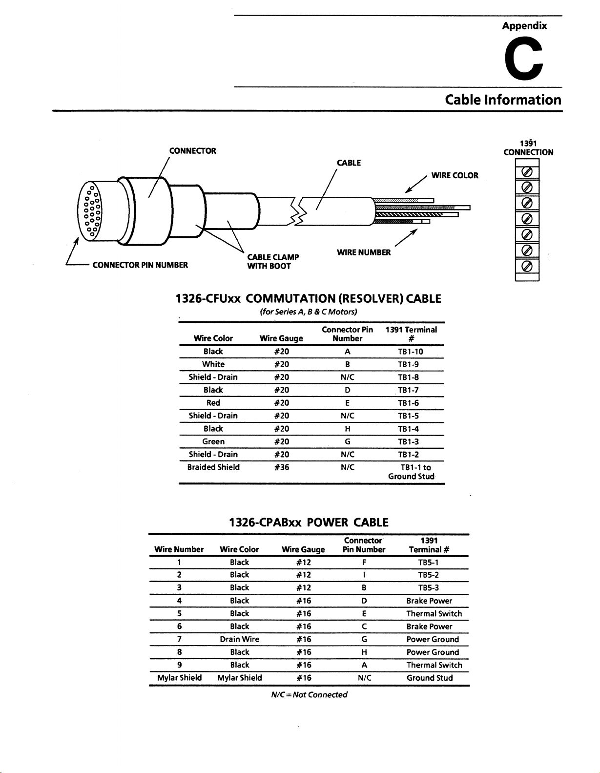
Appendix
c
(1
IP
<
°
oo
\
V°;
CONNECTOR
/
PIN
NUMBER
CONNECTOR
1326-CFUxx
Wire
Color
Black
White
•
Shield
Shield
Braided
Black
Black
Green
Shield
Red
-
-
Drain
Drain
Drain
Shield
CABLE
CABLE
WITH
CLAMP
BOOT
WIRE
COMMUTATION
(for
Wire
Series
Gauge
#20
#20
#20
#20
#20
#20
#20
#20
#20
#36
A,
B&C
Connector
Motors)
Number
NUMBER
(RESOLVER)
Pin
1391
A
B
N/C
D
E
N/C
H
G
N/C
N/C
TB1-10
TB1-9
TB1-8
TB1-7
TB1-6
TB1-5
TB1-4
TB1-3
TB1-2
TB1-1
Ground
WIRE
CABLE
Terminal
#
to
Stud
Cable
COLOR
Information
1391
CONNECTION
Wire
Mylar
Number
1
2
3
4
5
6
7
8
9
Shield
1
326-CPABxx
Wire
Color
Black
Black
Black
Black
Black
Black
Drain
Wire
Black
Black
Mylar
Shield
N/C
Wire
=
Not
POWER
Gauge
#12
#12
#12
#16
#16
#16
#16
#16
#16
#16
Connected
CABLE
Connector
Pin
Number
F
I
B
D
E
C
G
H
A
N/C
1391
Terminal
TB5-1
TB5-2
TB5-3
Power
Brake
Thermal
Brake
Power
Power
Power
Thermal
Ground
#
Switch
Ground
Ground
Switch
Stud
Page 82
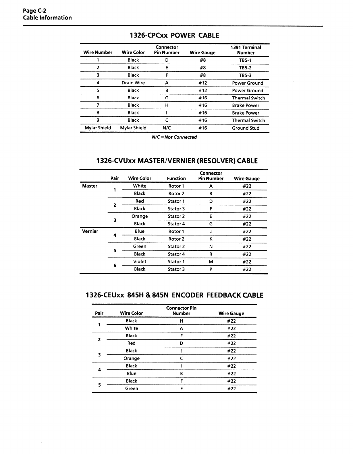
Page
Cable
C-2
Information
1
326-CPCxx
POWER
CABLE
Wire
Mylar
Master
Vernier
Number
1
2
3
4
5
6
7
8
9
Shield
326-CVUxx
1
Wire
Drain
Mylar
Pair
1
2
3
4
5
6
Color
Black
Black
Black
Wire
Black
Black
Black
Black
Black
Shield
Connector
Pin
Number
A
G
N/C
N/C
Not
=
D
E
F
B
H
I
C
Connected
MASTER/VERNIER
Wire
Color
White
Black
Red
Black
Orange
Black
Blue
Black
Green
Black
Violet
Black
Function
Rotor
Rotor
Stator
Stator
Stator
Stator
Rotor
Rotor
Stator
Stator
Stator
Stator
Gauge
Wire
#8
#8
#8
#12
#12
#16
#16
#16
#16
#16
(RESOLVER)
Connector
Pin
1
2
1
3
2
4
1
2
2
4
1
3
Number
A
B
D
F
E
G
J
K
N
R
M
P
1391
Terminal
Number
TB5-1
TB5-2
TB5-3
Power
Power
Thermal
Brake
Brake
Thermal
Ground
CABLE
Wire
#22
#22
#22
#22
#22
#22
#22
#22
#22
#22
#22
#22
Ground
Ground
Switch
Power
Power
Switch
Stud
Gauge
1326-CEUxx
Pair
1
2
3
4
5
Wire
845H&845N
Color
Black
White
Black
Red
Black
Orange
Black
Blue
Black
Green
ENCODER
Connector
Number
Pin
H
A
F
D
J
C
I
B
F
E
FEEDBACK
Gauge
Wire
#22
#22
#22
#22
#22
#22
#22
#22
#22
#22
CABLE
Page 83

Notes
Page 84

Notes
Page 85

Notes
Page 86

Notes
Page 87

Notes
Page 88

Notes
Page 89

I
We
manuals
can
You
By
that.
few
a
take
FAX:
PUBLICATION
PUBLICATION
CHECK
THE
SUGGEST
DESIGN
SUPERVISE
LEVEL
WHAT
PROGRAMMABLE
AC
/DC
PERSONAL
NC/CNC
DATA
COMMUNICATIONS
Our
help!
out
filling
minutes
your
to
DRIVES
CONTROLS
local
NAME
NUMBER,
FUNCTION
RESPONSIBLE
/
/
IMPLEMENT
FLOOR
EXPERIENCE
OF
CONTROL
COMPUTERS
this
to
Want
meet
must
can
you
form
you
what
us
tell
Allen-Bradley
AND
MOST
FOR
LAN
PART
CLEARLY
THE
YOU
DO
SYSTEMS
DATE
THAT
ELECTRICAL
OPERATIONS
/
Our
needs
the
helpusprovide
Then
think.
Office
Sales
PRESENT)
NUMBER
PURCHASE
HAVE
(IF
DESCRIBES
OF
WITH
EACH
NONE
Manuals
you,
of
EQUIPMENT
mail
or
the
most
or
414/5
YOUR
OF
THE
the
FAX
12-8579
This
user.
useful,
this
JOB.
FOLLOWING
LITTLE
your
is
thorough,
form.
MAINTAIN
TRAIN
/
PRODUCTS?
MODERATE
to
be
opportunity
accurate
and
OPERATE
/
EDUCATE
MACHINE
the
make
to
manuals
PROGRAMMABLE
USERS
EXTENSIVE
Best!
they
sure
available.
MACHINERY
do
just
Please
X
W
s
\z
o
a
o
<
u
RATE
HELPFULNESS
CLARITY
EASE
ACCURACY
QUALITY
QUALITY
WHAT
WHAT
PLEASE
I
I
NAME
TITLE
STREET
THE
OVERALL
USE
OF
AND
COMPARED
COMPAREDTOOTHER
DID
YOU
YOU
DID
LIST
YOU
HAVE
THE
QUALITY
INDEX
OF
COMPLETENESS
LIKE
MOST
LIKE
LEAST
ANY
ERRORS
ADDITIONAL
ANY
FOLLOWING.
OTHER
TO
OF
TABLE
/
ABOUT
ABOUT
YOU
MANUAL
THIS
CONTENTS
OF
COMPANIES’
ALLEN-BRADLEY
THIS
THIS
FOUND
COMMENTS?
CIRCLING
BY
MANUALS
MANUALS
MANUAL?
MANUAL?
IN
MANUAL
THIS
CITY
YOUR
RESPONSE
1
1
1
1
1
1
(REFERENCE
COMPANY
DEPARTMENT
PAGE,
BELOW.
2
2
2
2
2
2
TABLE,
(1)
3
3
3
3
3
3
FIGURE
OR
STATE
POOR
=
4
4
4
4
4
4
NUMBERS).
(5)
EXCELLENT
=
5
5
5
5
5
5
ZIP
TELEPHONE
]
DATE
Page 90

FOLD
FOLD
HERE
HERE
NO
POSTAGE
NECESSARY
MAILED
IF
IN
THE
STATES
UNITED
BUSINESS
FIRST
CLASS
POSTAGE
PERMIT
WILL
BE
REPLY
NO.
413
ADDRESSEE
PAID
BY
ALLEN-BRADLEY
Attn:
Marketing
P.O.
Box
Mequon,
1
Wl
1
Communications
760
53092-9907
Hi
M
III
id
Mi
ill
MEQUON,
i
M
MAIL
Wl
Ml
illJiill
1
1
mliiill
II
MI
Page 91

EfilaJ
With
A
||
rtLLtl\
ROCKWELL
A
offices
FN-RRAm
INTERNATIONAL
major
in
cities
DIX/'UJLt.
worldwide.
FY
COMPANY
subsidiary
A
I
meets
employees
products
to
manufacturing
decision-making
today’s
and
market.
Rockwell
of
automation
throughout
supporting
products
These
process
throughout
International,
challenges
design,
the
world
to
services
and
services
providing
while
enterprise.
the
of
the
one
with
over
manufacture
help
our
customers
only
not
access
world’s
years
85
control
to
vital
largest
practical
of
apply
a
and
continuously
individual
plant
floor
technology
plant
floor
range
wide
improve
machines,
can
data
that
companies,
experience.
of
control
productivity
quality,
integrate
but
also
to
used
be
Allen-Bradley
11,
Over
000
automation
and
and
the
support
time
HEADQUARTERS
WORLD
Allen-Bradley
South
1201
Milwaukee,
Tel:
Telex:
Fax:
Publication
Supersedes
Second
Wl
(1)
414382-2000
4311016
(1)414382-4444
1391-5.1
1391-5.1
Street
53204
November.
-
USA
-
EUROPE/MIDDLE
AFRICA
Allen-Bradley
Amsterdamseweg
AC
1422
The
Netherlands
(31)2975/43500
Tel:
(844)
Telex:
(31)2975/60222
Fax:
October.
1991
and
1992
the
following:
Europe
EAST/
B.V.
HEADQUARTERS
15
Uithoorn
18042
1391-5.1DU3
and
ASIA/PACIFIC
Allen-Bradley
1006,
Room
Watson
2-8
Kong
Hong
(852)
887-4788
Tel:
(780)64347
Telex:
(852)510-9436
Fax:
1326A-2.3DU1
HEADQUARTERS
(Hong
Kong)
B,
Sea
Block
View
Road
Limited
Estate
HEADQUARTERS
CANADA
Allen-Bradley
135
Cambridge,
Dundas
Canada
Street
Ontario
Canada
(1)519623-1810
Tel:
(1)519
Fax:
623-8930
Copyright
Limited
N1R
1992
5X1
Allen-Bradley
AMERICA
LATIN
HEADQUARTERS
Allen-Bradley
South
1201
Milwaukee,
Tel:
Telex:
Fax:
Company.
Second
Wl
53204
(1)414382-2000
016
11
43
(1)414382-2400
P/N
Printed
Inc.
Street
USA
141953
in
USA
 Loading...