

Allen-Bradley 1305-RFB-8-B, 1336-RFB-7-A, 1336-RFB-7-AA, 1336-RFB-16-AA, 1336-RFB-16-A User Manual
...Page 1

User
Manual
Input RFI Filters
Page 2

Page 3
Instructions
The Input RFI Filter units are designed to be used with the following
Allen-Bradley Adjustable Frequency AC Drives:
•1305
• 1336 PLUS
• 1336
PLUS II
• 1336 FORCE™
• 1336 IMPACT ™
The main function of the inp ut RFI filter is to re duce the radio f r e-
quency conducted emissions into the main supply lines and ground
wiring. This publication provides the steps needed to install the filter.
Important:
Declarations of Conformity to the European Union
Directives are available for Allen-Bradley AC Drive
Products. Please contact your Allen-Bradley Sales
Representative.
Refer to the page listed below for in stallation instructions.
• 1305 - See page 2
• 1336 PLUS/
PLUS II, FORCE and IMPACT - See page 5
!
ATTENTION: The Input RFI Filter connects between the
incoming AC supply line and the drive input terminals. The
filter must be installed by qualified personnel familiar with
the drive an d associated machine ry . Fail ure to comply may
result in personal injury and/or equipment damage.
!
ATTENTION: An incorrectly applied or installed Input
RFI Filter can result in component damage or a reduction
in product life. Wiring or application errors, such as
incorrect wiring lay out, incorrec t or inadequat e A C supply
or excessive ambient temperatures may result in
malfunction of the system.
Input RFI Filters
Page 4
2 Input RFI Filters
1305 Filter Install ation
Use the cross reference below to verify that the correct filter and kit
have been selected for your CE compatible drive.
Important:
Do not use the filters listed below in single-phase
applications. Consult factory for further information.
Filter Selection
Components Supplied
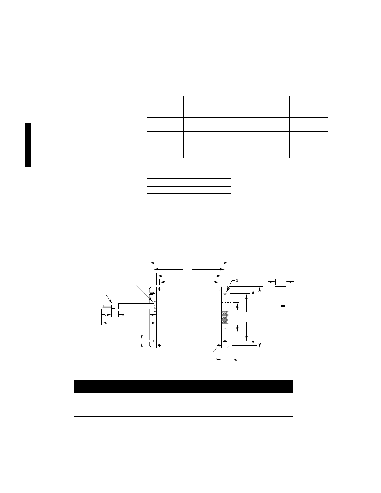
Filter Dimensions
Filter Catalog
Number
Power
Dissipation
Three-Phase
V olts Used with . . .
Metal Conduit
Panel Kit Catalog
Number
1305-RFB-05-A 4.2 Watts 200-240V 1305-AA02A, AA03A 1305-MP-05-A
1305-AA04A 1305-MP-06-A
1305-RFB-08-B 8.8 Watts 200-480V 1305-AA08A, BA01A,
BA02A, BA03A, BA04A,
BA06A
1305-MP-08-B
1305-RFB-12-C 10.3 Watts 200-480V 1305-AA12A, BA09A 1305-MP-12-C
Item Quantity
Filter w/Output Cable 1
Grounding Bracket 1
Metal Conduit Panel 1
Terminal Block Cover 1
Terminal Block Cover Adapter 1
Terminal Block Cover Nut 2
Hex Standoff 2
F
53.2
(2.09)
38.1
(1.50)
E
B
40.0 (1.57)
Braided Shield
250.0 (9.84)
M5
5.3 (0.21)
5.3 (0.21)
190.0 (7.48)
Clamp onto Braided Shield
H
DCG A
Catalog
Number
1305-RFB-5-A
1305-RFB-8-B
1305-RFB-12-C
A
122.0
(4.80)
172.0
(6.77)
212.0
(8.35)
B
235.0
(9.25)
235.0
(9.25)
235.0
(9.25)
C
40.5
(1.59)
40.5
(1.59)
42.0
(1.65)
D
90.0
(3.54)
140.0
(5.51)
180.0
(7.09)
E
215.0
(8.46)
215.0
(8.46)
215.0
(8.46)
F
180.0
(7.09)
180.0
(7.09)
180.0
(7.09)
G
110.0
(4.33)
160.0
(6.30)
200.0
(7.87)
H
195.0
(7.68)
195.0
(7.68)
195.0
(7.68)
All Dimensions in Millimeters and (Inches)
Weight
kg (lbs.)
0.85
(1.87)
0.95
(2.09)
1.05
(2.31)
English
Page 5
Input RFI Filters 3
1. Mount the filter to the panel. Refer to the Dimension drawing
shown on the previous page.
2. Remove and discard the plastic conduit panel of the 1305.
Replace with the supplied metal conduit panel.
3. Mount the grounding bracket to the conduit panel of the drive
using the supplied hardware.
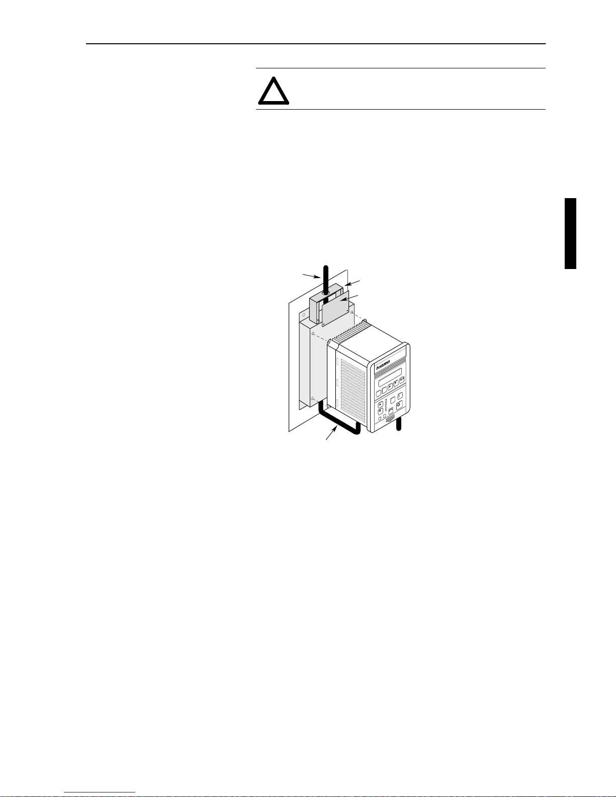
4. Using the figure below as guide, mount the drive to the filter.
Filter Mounting
5. The RFI filter must be connected between the incoming AC
supply line and the drive input terminals.
Important:
The filter may cause ground leakage currents.
Therefore a solid grou nd connection must be provid ed
as shown on the following page.
(NEMA T ype 1 only) Before con necting the A C input
lines, slide the T erminal Block Cov er Adapter onto the
wire. After wiring has been completed, slide the
adapter up to the filter and secure with supplied
standoffs. Place cover over adapter and secure with
supplied hardware.
!
ATTENTION: T o pre vent elec trical shock, disconnec t the
power source before installing or servicing.
Three-Phase
Input
1
Terminal Block Cover Adapter
Terminal Block Cover
J
O
G
ESC
SEL
To Motor
1
Cable Supplied with Filter
1
Input power (source to filter) and output power (filter to drive and drive to
motor) wiring must be in conduit or have shielding/armor with equivalent
attenuation. Shielding/armor must be bonded to the metal conduit panel.
E
ng
l
i
s
h
Page 6
4 Input RFI Filters
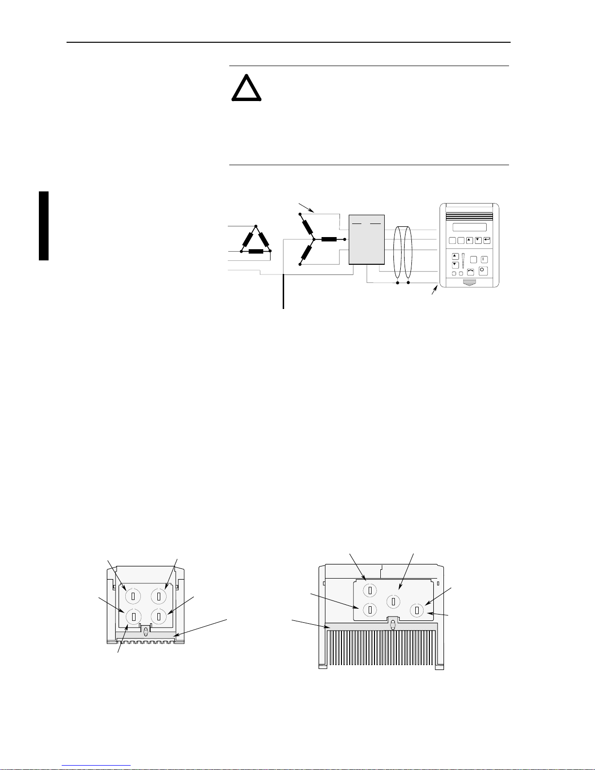
Filter Wiring - 1305
6. Connect remaining wires. Cables must use knockouts defined in
the figure below.
7. To assure that the RFI filter is effective and to reduce cable radia-
tion, the motor cable must be shielded or armored. The ground
conductor of the motor cable (drive end) must be connected
directly to the dri v e gro und t erminal , not to t he encl osure b us bar.
The shield must be bonded to the metal where the motor cable
exits the drive. At the motor end, the ground conductor should
also be connected to the motor case ground. The shield or armor
must be bonded to the filter (and drive). At the motor end, the
shield should also be connected to the motor case ground.
1305 Knockout Definitions
Dimensions are in Millimeters and (Inches)
!
ATTENTION: To guard against possible equipment
damage, RFI filters can only be use d with AC suppli es that
are nominally balanced with respect to ground. In some
installations, three-phase supplies are occasionally
connected in a 3-wire configuration with one phase
grounded (Grounded Delta). The f ilter mus t not be used i n
Grounded Delta supplies.
R (L1)
S (L2)
Ground Rod/Grid
or Building Structure Steel
T (L3)
GRD
Shield Terminated
in Cable Clamp
Conduit/4-Wire Cable
JOG
ESC SEL
L1
Line
L2
L3
E
L1’
Load
L2’
L3’
E’
RFI Filter
Frame A
(1305-AA02A, AA03A, AA04A)
Frames B and C
(1305-AA08A, AA12A, BA01A, BA02A, BA03A, BA04A, BA06A, BA09A)
Control I/O
Filter Input
Optional Brake
Motor Output
Grounding Bracket
Filter Input
Control I/O
Additional Control
Motor Output
18.6 (0.73) - 4 Plcs.
18.6 (0.73) - 4 Plcs.
English
Page 7

Input RFI Filters 5
1336 PLUS,
PLUS
II,
FORCE and
IMPACT Filter Installation
Use the cross reference below to verify that the correct filter has been
selected for your CE compatible drive. In addition, ensure that the
drive was ordered with the “-AE” enclosure option or the EMC
Enclosure Kit (1336x-AEx) has been properly installed.
Filter Selection
Components Included with Filter
Filter Catalog
Number
Filter
Series
Mounting
See . . .
(pg. 11-13)
Power
Diss.
(Watts)
Three-Phase
Volts
Used with . . .
Frame
Reference1336 PLUS/
PLUS
II
1336 FORCE 1336 IMPACT
1336-RFB-7-AA A Figure 1 4.5 200-240V 1336S/F-AQF05 - AQF10
N/A
1336E-AQF05 - AQF10 A1
380-480V 1336S/F-BRF05 - BRF20 1336E-BRF05 - BRF20 A1-A2
1336-RFB-7-A B Figure 1 or
Figure 2
2 200-240V 1336S/F-AQF05 - AQF10 1336E-AQF05 - AQF10 A1
380-480V 1336S/F-BRF05 - BRF20 1336E-BRF05 - BRF20 A1-A2
1336-RFB-16-AA A Figure 1 9 200-240V 1336S/F-AQF15 - AQF20 1336E-AQF15 - AQF20 A2
380-480V 1336S/F-BRF30 - BRF50 1336E-BRF30 - BRF50 A2-A3
1336-RFB-16-A B Figure 1 or
Figure 2
9.5 200-240V 1336S/F-AQF15 - AQF20 1336E-AQF15 - AQF20 A2
380-480V 1336S/F-BRF30 - BRF50 1336E-BRF30 - BRF50 A2-A3
1336-RFB-30-A A Figure 1 14 200-240V 1336S/F-AQF30 - AQF50 1336E-AQF30 - AQF50 A3
1336-RFB-30-A4 A Figure 2 35 380-480V 1336S/F-BRF75 - BRF200 1336E-BRF75 - BRF100 A4
1336-RFB-27-B A Figure 2 30 200-240V 1336S/F-A007 1336T-A001 - A007 1336E-A007 B
380-480V 1336S/F-B007 - B015 1336T-B001 - B015 1336E-B007 - B015 B
1336-RFB-48-B A Figure 2 56 200-240V 1336S/F-A010 - A015 1336T-A010 - A015 1336E-A010 - A015 B
380-480V 1336S/F-B020 - B030 1336T-B020 - B030 1336E-B020 - B030 B
1336-RFB-80-C A Figure 2 71 200-240V 1336S/F-A020 - A030 1336T-A020 - A030 1336E-A020 - A030 C
380-480V 1336S/F-BX040 - BX060 1336T-BX040 - BX060 1336E-BX040 - BX060 C
1336-RFB-150-D A Figure 3 or
Figure 4
90 200-240V 1336S/F-A040 - A050 1336T-A040 - A050 1336E-A040 - A050 D
380-480V 1336S/F-B060 - B100 1336T-B060 - B100 1336E-B060 - B100 D
1336-RFB-180-D A Figure 3 or
Figure 4
125 200-240V 1336S/F-A060 1336T-A060 1336E-A060 D
380-480V 1336S/F-B125 - BX150 1336T-B125 - BX150 1336E-B125 - BX150 D
1336-RFB-340-E A Figure 3 or
Figure 4
60 200-240V 1336S/F-A075 - A125 1336T-A075 - A125 1336E-A075 - A125 E
380-480V 1336S/F-B150 - B250 1336T-B150 - B250 1336E-B150 - B250 E
1336-RFB-475-G A Figure 5 61 380-480V 1336S/F-BP250 - BP350
1336F-BPR250 - BPR350
N/A 1336E-BP300 - BP350
1336E-BPR300 - BPR35 0
F
1336S/F-BX250 - B350 1336T-BX250 - B350 1336E-BX250 - B350 G
1336-RFB-590-G A Figure 5 94 380-480V 1336S/F-BP400 - BP450
1336F-BPR400 - BPR450
N/A 1336E-BP400 - BP450
1336E-BPR400 - BPR45 0
F
1336S/F-B400 - B450 1336T-B400 - B450 1336E-B400 - B450 G
1336-RFB-670-G A Figure 5 121 380-480V 1336S/F-B500 - B600 1336T-B500 - B600 1336E-B500 - B600 G
Item
Quantity - 1336-RFB- . . .
7-A, 16-A, 30-A 30-A4, 27-B, 48-B, 80-C 150-D, 180-D, 340-E 475-G, 590-G, 670-G
Filter 1 1 1 1
EMT Conduit –1 1 –
EMT Conduit Fitting – 1 2 –
Bolts – 4 8 3
Flat Washers – 4 – –
Star Washers – 4 – –
Terminal Block Housing 1 – – –
Standoffs 2 – – –
Nuts 3 4 – 3
E
ng
l
i
s
h
Page 8

6 Input RFI Filters
Filter Dimensions
B
100.0 (3.94)
Braided Shield
F
6.5 (0.26)
10.0 (0.39)
10.0 (0.39)
E
H
1.0 (0.04)
Catalog
Number
1336-RFB-7-AA
1336-RFB-16-AA
1336-RFB-30-A
A
50.0
(1.97)
55.0
(2.17)
60.0
(2.36)
B
255.0
(10.04)
305.0
(12.00)
335.0
(13.19)
C
126.0
(4.96)
142.0
(5.59)
160.0
(6.30)
D
25.0
(0.98)
30.0
(1.18)
35.0
(1.38)
E
240.0
(9.45)
290.0
(11.42)
320.0
(12.60)
F
180.0
(7.09)
230.0
(9.06)
280.0
(11.02)
H
225.0
(8.86)
275.0
(10.83)
305.0
(12.00)
All Dimensions in Millimeters and (Inches)
D
TB Cover = 50.0 (1.97) x 41.0 (1.61) x 66.0 (2.60)
A
C
Weight
kg (lbs.)
1.1
(2.4)
1.7
(3.8)
1.8
(4.0)
B
40.0 (1.57)
280.0
(11.02)
70.0
(2.76)
2.1
mm2 (14 AWG)
F
6.5 (0.26)
E
H
Catalog
Number
1336-RFB-7-A & 16-A
Series B
B
390.0
(15.35)
A
215.9
(8.50)
C
58.0
(2.28)
D
30.0
(1.18)
E
375.0
(14.76)
F
275.0
(10.83)
G
7.5
(0.30)
H
360.0
(14.17)
I
185.2
(7.29)
All Dimensions in Millimeters and (Inches)
D
C
G
IA
6.3 (0.25) Dia.
4 Places
English
Page 9

Input RFI Filters 7
Filter Dimensions
(continued)
H
Front View
Side View
Top
D
G
C
A
E
B
Catalog
Number
1336-RFB-150-D,
1336-RFB-180-D
1336-RFB-340-E
A
270.0
(10.63)
377.0
(14.84)
B
1200.0
(47.20)
1392.0
(54.80)
C
147.2
(5.80)
155.0
(6.10)
D
204.0
(8.03)
308.0
(12.13)
E
1159.4
(45.65)
1346.1
(53.00)
F
20.3
(0.80)
23.0
(0.91)
G
20.3
(0.80)
23.0
(0.91)
H
1108.3
(43.63)
1265
(49.80)
F
Mounting Hole Detail
Dia. 10.1 (0.41)
14.8 (0.58)
Dia. 18.8 (0.75)
All Dimensions in Millimeters and (Inches)
Weight
kg (lbs.)
25.0
(55.1)
37.0
(81.6)
EG
C
B
D
H
H
F
Conduit Fitting
A
Catalog
Number
1336-RFB-30-A4
1336-RFB-27-B
1336-RFB-48-B
1336-RFB-80-C
A
260.1
(10.24)
276.6
(10.89)
276.6
(10.89)
302.0
(11.89)
B
413.7
(16.29)
540.0
(21.26)
540.0
(21.26)
775.0
(30.50)
C
58.0
(2.28)
58.0
(2.28)
68.1
(2.68)
78.5
(3.09)
D
230.1
(9.06)
212.6
(8.37)
212.6
(8.37)
238.0
(9.37)
E
320.0
(12.60)
461.0
(18.15)
461.0
(18.15)
685.8
(27.00)
F
15.0
(0.59)
10.9
(0.43)
10.9
(0.43)
20.4
(0.80)
G
70.0
(2.76)
68.1
(2.68)
68.1
(2.68)
68.8
(2.70)
H
15.0
(0.59)
32.0
(1.26)
32.0
(1.26)
32.0
(1.26)
Weight
kg (lbs.)
4.9
(10.8)
7.0
(15.4)
8.5
(18.7)
12.0
(26.5)
E
ng
l
i
s
h
Page 10

8 Input RFI Filters
Filter Dimensions
(continued)
EFEE
122.0 (4.08)122.0 (4.08)
F
B
5.0 (0.20) Dia. Ground Stud
H
D
C
A
G
Catalog
Number
1336-RFB-475-G
1336-RFB-590-G
1336-RFB-670-G
A
300.0
(11.81)
B
794.0
(31.26)
C
160.0
(6.30)
D
275.0
(10.83)
E
200.0
(7.87)
F
70.0
(2.76)
G
12.5
(0.49)
H
740.0
(29.13)
Weight
kg (lbs.)
29.0
(63.9)
English
Page 11

Input RFI Filters 9
1. Perform the appropriate step be low (A, B, C, D or E) t o mount the
filter and drive.
A. 1336-RFB-7-AA, 16-AA, 30-A Filters
Mount the filter and drive to the panel. See the Dimension &
Mounting diagrams provided in this document. Drive mounting information can be found in the User Manual.
B. 1336-RFB-7-A, 16-A Series B Filters
Two mounting methods are available; filter and drive (as one
assembly) or side-by-side. Choose the method that best suits
your application, then refer to the Dimension information on
page 6 and mounting diagram on page 11. Drive mounting
information can be found in the User Manual.
Important:
Hardware must be installed as shown in the
Mounting diagram on page 11.
C. 1336-RFB-30-A4, 27-B, 48-B, 80-C Filters
Using the supplied hardware, mount the filter and drive (as
one assembly) to the panel. Hardware must be installed as
shown in Figure 2 on page 11.
D. 1336-RFB-150-D, 180-D, 340-E Filters
a) Moun t the drive to t he pane l usi ng the Mount ing di agram
provided in this document as a guide. Drive mounting
information can be found in the User Manual.
b) Using the Dimension and Mounting diagrams provided,
correctly orient and temporarily mount the filter (using
top mounting hole(s) only) to the enclosure back plane.
Important:
Filter must be carefully positioned for proper
alignment with the conduit box (and drive).
c) Insert lower filter bolt(s) and secure all hardware.
Remove the lower filter access panel and conduit box
cover.
d) Attach the conduit box to both the filter and drive using
the two nipples/fittings and locknuts provided. Refer to
the diagram on page 14 for knockout definitions and
mounting point for conduit box.
e) Route filt er output leads thr ough the con duit box and into
the drive. Replace access panel and conduit box cover.
E. 1336-RFB-475-G, 590-G, 670-G Filters
Mount the filter using the Dimension & Mounting diagrams
provided in this document. Drive mounting information can
be found in the User Manual.
!
ATTENTION: T o pre vent electr ical shock, disconnect the
power source before installing or servicing.
E
ng
l
i
s
h
Page 12

10 Input RFI Filters
2. The RFI filter must be connected between the incoming AC
supply line and the drive input terminals.
Important:
The filter may cause ground leakage currents.
Therefore a solid grou nd connection must be provided
as shown below.
Remove the f ilte r access pan el (or terminal block co ver) to expos e
the input terminal block. Connect the incoming AC lines (see
note 1) to the appropriate terminals on the block ("Line/L1, L2,
L3"). Replace access panel/cover.
Incoming AC lines are connected to 1336-RFB-475, 590, 670
filters at the lower set of filter bus bars.
1
Input power (source to filter) wiring must be in conduit or have shielding/armor with equivalent
attenuation.
Filter Wiring - 1336 PLUS/
PLUS
II,
FORCE & IMPACT
3. Connect remaining wires. Cables must use knockouts as defined
on page 14.
4. To assure that the RFI filter is effective and to reduce cable
radiation, all cables entering and/or exiting the filter/drive must
be shielded or armored. The ground co nductor of the motor ca ble
(drive end) must be connected directly to the drive ground
terminal, no t to the enclosu re bus bar. At the motor end, the
ground conductor should also be connected to the motor case
ground. The shield or armor should be bonded to the filter (and
drive). At the motor end, the shield should also be connected to
the motor case ground.
!
ATTENTION: To guard against possible equipment
damage, RFI filter s can only b e used with A C su pplies that
are nominally balanced (and grounded) with respect to
ground. In some installations, three-phase supplies are
occasionally connected in a 3-wir e conf i gurat ion with one
phase grounded (Grounded Delta). The filter must not be
used in Grounded Delta supplies.
JOG
ESC SEL
R (L1)
S (L2)
T (L3)
L1
Line
L2
L3
E
L1’
Load
L2’
L3’
E’
PE
Conduit/4-Wire Cable
RFI Filter
Shield Terminated in Cable
Clamp on A Frame Drives
Nearest
Building Structure Steel
English
Page 13

Input RFI Filters 11
Filter Mounting
Series B Filters can be mounted using either method
1
Input power (source to filter) and output power (filter to drive and drive to motor) wiring must be in conduit or have shielding/armor with equ ival ent at tenu atio n. Shi eldin g/
armor must be bonded to the metal bottom plate.
2
Refer to the Filter Selection table on page 5 for frame references and corresponding catalog numbers.
To Motor
1
Cable Supplied with Filter
1
Conduit
1
To Motor
1
Three-Phase Input
1
Access
Panel
Flat Washer
Star Washers
Bolt
Bolt
Important: Drive and filter must be
mounted to a common back plane
with a positive electrical bond and in
close proximity to one another.
Important: A positive electrical bond must be
maintained between drive and filter at all 4
corners. Star washers can be eliminated
if a positive electrical bond is
assured.
Three-Phase
Input
1
Figure 1 (Side-by-Side)
1336 PLUS &
PLUS
II
Frames A1 - A3
2
Figure 2 (One Assembly)
1336 PLUS,
PLUS II,
FORCE & IMPACT
Frames A4, B & C
2
E
ng
l
i
s
h
Page 14

12 Input RFI Filters
Filter Mounting
(continued)
1
Input power (source to filter) and output power (filter to drive and drive to motor) wiring must be in conduit or have shielding/armor with equivalent attenuation. Shielding/
armor must be bonded to the metal bottom plate.
2
Refer to the Filter Selection table on page 5 for frame references and corresponding catalog numbers.
Conduit Box
1
To Motor
1
Access Panel and
Input Terminal Block
Lower Access Panel
Important: Drive and filter must be mounted
to a common back plane with a positive
electrical bond. Spacing is determined by
Conduit Box.
Three-Phase
Input
1
To Motor
1
Three-Phase
Input
1
Conduit Box
1
Nipple/Fitting
Figure 3
1336 PLUS,
PLUS II,
FORCE & IMPACT
(Through-the-Wall Mounting)
Frames D & E
2
Figure 4
1336 PLUS,
PLUS II,
FORCE & IMPAC T
(Conventional Mounting)
Frames D & E
2
English
Page 15

Input RFI Filters 13
Filter Mounting
(continued)
1
Input power (source to filter) and output power (filter to drive and drive to motor) wiring must be in conduit or have shielding/armor with equivalent attenuation. Shielding/
armor must be bonded to the metal bottom plate.
2
Refer to the Filter Selection table on page 5 for frame references and corresponding catalog numbers.
75.0
(2.95)
Mounting Brackets
Typical Drive Placement
to Drive Input
Terminals
AC Input Terminals
Typical Bracket
for Stability
(G Frame Only - Mount between PE Terminals & Enclosure)
831.0
(32.72)
All Dimensions in Millimeters and (Inches)
Figure 5
1336 PLUS,
PLUS II,
FORCE & IMPAC T
(Typical Filter Mounting)
Frames F & G
1, 2
Important: This information represents the
method used to mount 1336-RFB-475, 590 &
670 filters in an Allen-Bradley supplied EMC
enclosure. User supplied EMC enclosures must
follow all of the guidelines shown. Illustrations
are only intended to identify structural mounting
points and hardware shapes. You must design
and fabricate steel components based on the
actual mounting configuration, calculated loads
and enclosure specifications. Refer to the drive
User Manual for drive mounting requirements.
Important: Cooling fans are required for proper
drive operation. Fans and air intake openings
must be EMI shielded. Refer to the drive User
Manual for CFM recommendations.
Important: A positive electrical bond must be maintained
between the enclosure and filter (including brackets), fans,
and drive. To assure a positive electrical bond, any paint
near all mounting points must be removed.
E
ng
l
i
s
h
Page 16

14 Input RFI Filters
1336 PLUS,
PLUS
II,
FORCE & IMPACT Knockout Definitions
Dimensions are in Millimeters and (Inches)
Frames B and C
Frames A1 through A4
Frame E
Frame D
Control I/O
Control I/O
Control I/O
Filter Input
Filter Input
Filter Input
Filter Input
SCANport
Motor Output
Motor Output
Motor Output
Motor Output
SCANport
SCANport
SCANport
(Side of Drive)
Control I/O
28.6/34.9 (1.13/1.38) - 3 Plcs.
22.2 (0.88) - 1 Plc.
22.2 (0.88) - 1 Plc.
22.2/28.6 (0.88/1.13) - 3 Plcs.
88.9/104.8 (3.50/4.13)
2 Plcs.
12.7 (0.50)
3 Plcs.
34.9 (1.38) - 3 Plcs.
34.9/50.0 (1.38/1.97) - 1 Plc.
62.7/76.2 (2.47/3.00) - 2 Plcs.
English
Page 17

Page 18

Publication RF-101ML-EN – December, 1999 P/N 74103-446-01 (06)
Supersedes July, 1999 Copyright 1999 Rockwell In ternational Corporation. A ll rights reserved. Printed in USA.
 Loading...