


Allen-Bradley
SCADA System
(Publication AG-6.5.8)
Application
Guide

Important User Information Because of the variety of uses for the products described in this
publication, those responsible for the application and use of this
control eq uipment must satisfy themselves that all necessary steps
have been taken to assure that each application and use meets all
performance and safety requirements, including any applicable laws,
regulations, codes and standards.
The illustrations, charts, sample programs and layout examples
shown in this guide are intended solely for purposes of example.
Since there are many variables and requirements associated with any
particular installation, Allen-Bradley does not assume responsibility
or liability (to include int ellectual property liability ) for actual use
based upon the examples shown in this publication.
Allen-Bradley publication SGI–1.1, Safety Guidelines for the
Application, Installation, and Maintenance of Solid State Control
(available from your local Allen-Bradley office), describes some
important differences between solid-state equipment and
electromechanical devices that should be taken into consideration
when applying products such as those described in this publication.
Reproduction of the contents of this copyrighted publication, in
whole or in part, without written permission of Allen-Bradley
Company, Inc., is prohibited.
Throughout this manual we use notes to make you aware of safety
considerations:
ATTENTION: Identifies information about practices
!
Attention statements help you to:
• identify a hazard
• avoid the hazard
• recognize the consequences
Important: Identifies information that is critical for su ccessful
or circumstances that can lead to personal injury or
death, property damage or economic loss.
application and understanding of the product.
Publication AG-6.5.8 - October 1998

Summary of Changes
Introduction This document has been revised since the June 1996 printing.
Changes to this document are so extensive, that it is impractical to
mark every change with a revision bar in the margin of the page. The
purpose of this section is to outline the changes in the SCADA
Application Guide.
Scope of Changes This SCADA Application Guide represents the latest developments
in Allen-Bradley hardwar e and software, and i ncludes the most rece nt
third-party supplier information as it relates to SCADA applications.
Changes incorporated in this document include:
• The updating of the enhanced PLC-5 chapter (Chapter 2),
including new screen captures from RSLogix 5 and messaging
details.
• The restructuring of the SLC 5/03, 5/04 chapter (Chapter 4) to
include the SLC 5/05, new screen captures from RSLogix 500
and messaging details.
• The addition of a MicroLogix chapter, (Chapter 6) which details
the use of MicroLogix controllers in SCADA applications.
• The addition of a Logix5550 chapter, (Chapter 7) which details
the use of the Logix5550 controller in SCADA applications.
• Updated third-party modem documentation (Chapter 8).
• The addition of a RSLinx c hapter, which details the conf iguration
of the RSLinx DF1 Polling Ma st er a nd DF1 Slave drivers for use
in SCADA applications.
• The addition of an appendix (Appendix E) which provides
detailed examples of messaging ladder logic that is typical to
SCADA applications.
Publication AG-6.5.8 - October 1998

Preface
What SCADA Information
Two principle SCADA documents are available:
Is Available?
Flexible Solutions for Your
SCADA Needs
SCADA System Selection Guide
SCADA System Selection Guide
Publication AG-2.1
• Presents A-B capabilities
for SCADA applications
• Guides you through
choosing SCADA system
components
SCADA System Application Guide
Publication AG-6.5.8 (this manual)
• Describes how to configure
A-B products and third-party
modems
• Describes how to send
messages
• Gives application samples
Audience We designed this document for individuals who are configuring a
SCADA system or are answering configuration questions. This
document assumes you know how to:
• handle, install, and operate the produc ts referenced in this
document
• install, navigate through, and use the software products
referenced in this document
• prepare cables, if necessary
Publication AG-6.5.8 - October 1998

ii
Book Overview
Design
chapter 1
Designing Communication
Configure
Apply
chapter 2
Configuring Enhanced PLC-5
Processors
chapter 5
Configuring SLC 500
Processors with 1747-KE
Interface Modules
chapter 8
Configuring Modems
chapter 10
Using Dial-up Telephone
Communication
chapter 3
Configuring Classic PLC-5
Processors with 1785-KE
Modules
chapter 6
Configuring MicroLogix
Controllers
Configuring RSLinx 2.0
Software for DF1 Half-duplex
Communications
Remotely Programming
PLC-5 and SLC 500
chapter 4
Configuring SLC-5/03,5/04
and 5/05 Processors
chapter 7
Configuring Logix5550
Processors
chapter 9
chapter 11
Processors
Modem Cable Reference
Reference
Publication AG-6.5.8 - October 1998
appendix A
appendix D
Worksheets
appendix B
Basic DF1 Protocol
Troubleshooting
appendix E
Sample Ladder Logic
appendix C
Third-Party Supplier Contact
Information
Glossary

Terms We use these terms frequently in this book:
Term: Definition:
Classic PLC–5 processor A collective name used to refer to PLC–5/10, –5/12,
–5/15, and –5/25 processors.
Enhanced PLC–5 processor A collective name used to refer to PLC–5/11, –5/20,
–5/30, –5/40, –5/60, and PLC–5/80 processors.
Ethernet PLC–5 processor A collective name used to refer to PLC–5/20E, –5/40E, and
–5/80E processors.
master station A device (programmable controller with I/O modules or a
workstation) that sends data to and collects data from
devices connected on a point-to-multipoint, half-duplex
network.
slave station A device (programmable controller with I/O modules) that
is located in a remote site away from the master station
and that controls I/O points at the remote site. A slave
station accepts commands from and can send data (if
capable) to a master station via a telemetry network.
See the Glossary for other definitions.
Conventions This section explains the following conventions:
iii
• addresses
• identifying where you are within the manual
Addresses
These values: Are represented like:
octal
decimal
X
8
X
10
Publication AG-6.5.8 - October 1998

iv
Related Publications Use these manuals as necessary::
Title: Publication Number:
Automation Systems Catalog
Enhanced and Ethernet PLC–5 Programmable Controllers User
Manual
Classic PLC–5™ Family Programmable Controllers Hardware
Installation Manual
1785 PLC–5 Family Programmable Controllers Quick
Reference
PLC–5 Instruction Set Reference Manual 1785–6.1
1785–KE DH+ Communications Interface Module User Manual 1785–6.5.2
SLC 500™ and MicroLogix™ 1000 Instruction Set Reference
Manual
SLC 500 Modular Hardware Style Installation and Operation
Manual
DH–485/RS232C Interface Module User Manual 1747–6.12
MicroLogix™ 1000 Programmable Controllers Users Manual 1761-6.3
Logix5550 Controller User Manual 1756-6.5.12
Logix5550 Controller Programming Manual 1756-6.4.1
1785–6.5.12
1785–6.6.1
1785–7.1
1747–6.15
1747–6.2
Publication AG-6.5.8 - October 1998

Table of Contents
Chapter 1
Designing Communication Use This Chapter . . .. . . . . . . . . . . . . . . . . . . . . . . . . . . . . . . . . . . . . 1-1
Choosing a Polling Mode for DF1 Half-Duplex Master. . . . . . . . . . . . . 1-2
Message-Based Polling Mode . . . . . . . . . . . . . . . . . . . . . . . . . . . . 1-2
Standard Polling Mode. . . . . . . . . . . . . . . . . . . . . . . . . . . . . . . . . . 1-3
About Slave-to-Slave Messaging . . . . . . . . . . . . . . . . . . . . . . . . . 1-5
Addressing Tips . . . . . . . . . . . . . . . . . . . . . . . . . . . . . . . . . . . . . 1-5
Communication Scheme Design Using Standard-Mode . . . . . . . . . . . 1-6
Designing a Polling Scheme . . . . . . . . . . . . . . . . . . . . . . . . . . . 1-10
Planning for Timing Issues . . . . . . . . . . . . . . . . . . . . . . . . . . . . 1-12
Design Considerations . . . . . . . . . . . . . . . . . . . . . . . . . . . . . . . . . 1-12
Communication Scheme Design Using Message-based Mode . . . . . 1-14
Designing Communication
for Full-Duplex Protocol. . . . . . . . . . . . . . . . . . . . . . . . . . . . . . . 1-14
What to Do Next?. . . . . . . . . . . . . . . . . . . . . . . . . . . . . . . . . . . . . . . 1-16
Chapter 2
Configuring Enhanced PLC-5
Processors
Use This Chapter... . . . . . . . . . . . . . . . . . . . . . . . . . . . . . . . . . . . . . . 2-1
Overview. . . . . . . . . . . . . . . . . . . . . . . . . . . . . . . . . . . . . . . . . . . . . . 2-1
Installing the Processor . . . . . . . . . . . . . . . . . . . . . . . . . . . . . . . . . . . 2-2
Configuring a DF1 Half-Duplex Standard Mode Master Station. . . . . . 2-3
Define the Communication Driver Characteristics . . . . . . . . . . . . . 2-4
Displaying System (Master) Channel Status . . . . . . . . . . . . . . . . . . 2-6
Create Station Lists . . . . . . . . . . . . . . . . . . . . . . . . . . . . . . . . . . . . 2-7
Monitor Active Stations . . . . . . . . . . . . . . . . . . . . . . . . . . . . . . . . . 2-8
Configuring a DF1 Half-Duplex Message-based Mode
Master Station. . . . . . . . . . . . . . . . . . . . . . . . . . . . . . . . . . . . . . . 2-9
Configuring the Processor
as a Slave Station . . . . . . . . . . . . . . . . . . . . . . . . . . . . . . . . . . . 2-13
Displaying Slave System Channel Status . . . . . . . . . . . . . . . . . . . 2-16
Configuring the Processor as a Station on a Point-to-Point Link. . . . 2-18
Displaying Point-to-Point System Channel Status. . . . . . . . . . . . . 2-20
Messaging. . . . . . . . . . . . . . . . . . . . . . . . . . . . . . . . . . . . . . . . . . . . 2-21
Master Station to Slave Station . . . . . . . . . . . . . . . . . . . . . . . . . 2-21
Polled Report-by-Exception . . . . . . . . . . . . . . . . . . . . . . . . . . . . 2-21
Processor-to-Processor . . . . . . . . . . . . . . . . . . . . . . . . . . . . . . 2-22
Considerations When Configuring MSG Control Blocks . . . . . . . . 2-23
Example MSG Control Blocks . . . . . . . . . . . . . . . . . . . . . . . . . . 2-24
Publication AG-6.5.8 - October 1998

ii Table of Contents – SCADA System Selection Guide
Chapter 3
Configuring Classic PLC-5
Processors with 1785-KE Modules
Configuring SLC 5/03, 5/04
and 5/05 Processors
Use This Chapter. .. . . . . . . . . . . . . . . . . . . . . . . . . . . . . . . . . . . . . . 3-1
Overview. . . . . . . . . . . . . . . . . . . . . . . . . . . . . . . . . . . . . . . . . . . . . . 3-1
Installing the Processor . . . . . . . . . . . . . . . . . . . . . . . . . . . . . . . . . . . 3-2
Configuring and Installing
the 1785-KE Module . . . . . . . . . . . . . . . . . . . . . . . . . . . . . . . . . . 3-3
Connecting the Processor
and 1785-KE Module. . . . . . . . . . . . . . . . . . . . . . . . . . . . . . . . . . 3-4
Messaging. . . . . . . . . . . . . . . . . . . . . . . . . . . . . . . . . . . . . . . . . . . . . 3-5
Polled Report-by-Exception . . . . . . . . . . . . . . . . . . . . . . . . . . . . . . 3-5
Processor-to-Processor . . . . . . . . . . . . . . . . . . . . . . . . . . . . . . . . . 3-5
Considerations When Configuring MSG Control Blocks . . . . . . . . . 3-6
Example MSG Control Blocks . . . . . . . . . . . . . . . . . . . . . . . . . . . 3-6
Chapter 4
Use This Chapter.... . . . . . . . . . . . . . . . . . . . . . . . . . . . . . . . . . . . . . 4-1
Overview. . . . . . . . . . . . . . . . . . . . . . . . . . . . . . . . . . . . . . . . . . . . . . 4-1
Installing the Processor . . . . . . . . . . . . . . . . . . . . . . . . . . . . . . . . . . . 4-2
Using Modems that Support DF1 Communication Protocols . . . . . . . . 4-2
Dial-up Phone Modems . . . . . . . . . . . . . . . . . . . . . . . . . . . . . . . . . 4-2
Leased-Line Modems . . . . . . . . . . . . . . . . . . . . . . . . . . . . . . . . . . 4-3
Radio Modems. . . . . . . . . . . . . . . . . . . . . . . . . . . . . . . . . . . . . . . . 4-3
Line Drivers . . . . . . . . . . . . . . . . . . . . . . . . . . . . . . . . . . . . . . . . . . 4-3
Modem Control Line Operation. . . . . . . . . . . . . . . . . . . . . . . . . . . . . . 4-4
DF1 Full-Duplex. . . . . . . . . . . . . . . . . . . . . . . . . . . . . . . . . . . . . . . 4-4
No Handshaking Selected . . . . . . . . . . . . . . . . . . . . . . . . . . . . . . . 4-4
Full-Duplex Modem Selected . . . . . . . . . . . . . . . . . . . . . . . . . . . . . 4-4
DF1 Half-Duplex Slave. . . . . . . . . . . . . . . . . . . . . . . . . . . . . . . . . . 4-4
No Handshaking Selected . . . . . . . . . . . . . . . . . . . . . . . . . . . . . . . 4-4
Half-Duplex Modem with Continuous Carrier Selected . . . . . . . . . . 4-5
Half-Duplex Modem without Continuous Carrier Selected. . . . . . . . 4-5
DF1 Half Duplex Master. . . . . . . . . . . . . . . . . . . . . . . . . . . . . . . . . 4-5
No Handshaking Selected . . . . . . . . . . . . . . . . . . . . . . . . . . . . . . . 4-5
Full-Duplex Modem Selected . . . . . . . . . . . . . . . . . . . . . . . . . . . . . 4-5
Half-Duplex Modem without Continuous Carrier Selected. . . . . . . . 4-5
Configuring DF1 Half-Duplex Channel 0 Parameters . . . . . . . . . . . . . 4-6
RTS Send Delay and RTS Off Delay . . . . . . . . . . . . . . . . . . . . . . . . 4-6
Configuring a Standard-Mode DF1 Half-Duplex Master Station . . . . . 4-7
Minimum DF1 Half-Duplex Master Channel 0 ACK Timeout . . . . . 4-10
Determining Minimum Master ACK Timeout. . . . . . . . . . . . . . . . . 4-10
DF1 Half-Duplex Master Channel Status. . . . . . . . . . . . . . . . . . . . 4-12
Monitor Active Stations . . . . . . . . . . . . . . . . . . . . . . . . . . . . . . 4-13
Configuring a Message-based Mode DF1 Half-Duplex
Master Station. . . . . . . . . . . . . . . . . . . . . . . . . . . . . . . . . . . . . . 4-14
Configuring a Slave Station . . . . . . . . . . . . . . . . . . . . . . . . . . . . . . . 4-17
Configuring Channel 0 Poll Timeout . . . . . . . . . . . . . . . . . . . . . . . . . 4-19
DF1 Half-Duplex Slave Channel Status. . . . . . . . . . . . . . . . . . . . . 4-20
Configuring a Station on a Point-to-Point Link . . . . . . . . . . . . . . . . . 4-21
DF1 Full-Duplex Channel Status. . . . . . . . . . . . . . . . . . . . . . . . . . 4-23
Messaging. . . . . . . . . . . . . . . . . . . . . . . . . . . . . . . . . . . . . . . . . . . . 4-25
Publication AG-6.5.8 - October 1998

Table of Contents – SCADA System Appl ication Guide iii
Master Station to Slave Station . . . . . . . . . . . . . . . . . . . . . . . . . . 4-25
Polled Report-by-Exception . . . . . . . . . . . . . . . . . . . . . . . . . . . . . 4-25
Processor-to-Processor . . . . . . . . . . . . . . . . . . . . . . . . . . . . . . . . 4-25
Considerations When Configuring MSG Control Blocks . . . . . 4-26
For both Point-to-Multipoint and Point-to-Point Link Configurations . 4-
26
Minimum Master MSG Block Message Timeout . . . . . . . . . . . . . . 4-26
Message-based Polling Mode . . . . . . . . . . . . . . . . . . . . . . . . . . . 4-27
Standard Polling Mode. . . . . . . . . . . . . . . . . . . . . . . . . . . . . . . . . 4-28
Standard Polling Mode With Single Message Transfer . . . . . . . . . 4-28
Standard Polling Mode With Multiple Message Transfer. . . . . . . . 4-28
Minimum Slave MSG Block Message Timeout . . . . . . . . . . . . . . . 4-30
Minimum Point-to-Point MSG Block Message Timeout. . . . . . . . . 4-30
Example MSG Control Blocks . . . . . . . . . . . . . . . . . . . . . . . . . . . . 4-30
Chapter 5
Configuring SLC 500™
Processors with 1747-KE
Interface Modules
Configuring MicroLogix
Controllers
Use This Chapter.... . . . . . . . . . . . . . . . . . . . . . . . . . . . . . . . . . . . . . 5-1
Overview. . . . . . . . . . . . . . . . . . . . . . . . . . . . . . . . . . . . . . . . . . . . . . 5-1
Installing the Processor . . . . . . . . . . . . . . . . . . . . . . . . . . . . . . . . . . . 5-1
Installing the 1747-KE
Interface Module . . . . . . . . . . . . . . . . . . . . . . . . . . . . . . . . . . . . . 5-2
Configuring the Processor . . . . . . . . . . . . . . . . . . . . . . . . . . . . . . . . . 5-3
Configuring the 1747-KE
Interface Module . . . . . . . . . . . . . . . . . . . . . . . . . . . . . . . . . . . . . 5-3
Prepare to Configure the Driver . . . . . . . . . . . . . . . . . . . . . . . . . . . 5-3
Configure the DF1 Protocol Driver . . . . . . . . . . . . . . . . . . . . . . . . . 5-6
Save the Configuration. . . . . . . . . . . . . . . . . . . . . . . . . . . . . . . . . 5-11
Messaging . . . . . . . . . . . . . . . . . . . . . . . . . . . . . . . . . . . . . . . . . . . 5-11
Polled Report-by-Exception . . . . . . . . . . . . . . . . . . . . . . . . . . . . 5-11
Processor-to-Processor . . . . . . . . . . . . . . . . . . . . . . . . . . . . . . . 5-12
Considerations When Configuring MSG Control Blocks . . . . . . . . 5-12
Point-to-Multipoint and Point-to-Point Link Configurations. . . . . . 5-12
Point-to-Multipoint Link Configurations . . . . . . . . . . . . . . . . . . . . 5-13
Point-to-Point Link Configurations . . . . . . . . . . . . . . . . . . . . . . . . 5-13
Example MSG Control Blocks . . . . . . . . . . . . . . . . . . . . . . . . . 5-13
Chapter 6
Use This Chapter.... . . . . . . . . . . . . . . . . . . . . . . . . . . . . . . . . . . . . . 6-1
Overview. . . . . . . . . . . . . . . . . . . . . . . . . . . . . . . . . . . . . . . . . . . . . . 6-1
Installing the Controller . . . . . . . . . . . . . . . . . . . . . . . . . . . . . . . . . . . 6-2
Isolated Connections . . . . . . . . . . . . . . . . . . . . . . . . . . . . . . . . . . . 6-3
Automatic Protocol Switching . . . . . . . . . . . . . . . . . . . . . . . . . . . . . . 6-3
Using Modems that Support DF1 Communication Protocols . . . . . . . . 6-4
Dial-up Phone Modems . . . . . . . . . . . . . . . . . . . . . . . . . . . . . . . . . 6-4
Leased-Line Modems . . . . . . . . . . . . . . . . . . . . . . . . . . . . . . . . . . 6-5
Radio Modems. . . . . . . . . . . . . . . . . . . . . . . . . . . . . . . . . . . . . . . . 6-5
Line Drivers . . . . . . . . . . . . . . . . . . . . . . . . . . . . . . . . . . . . . . . . . . 6-5
Modem Control Line Operation. . . . . . . . . . . . . . . . . . . . . . . . . . . . . . 6-6
DF1 Full-Duplex Operation. . . . . . . . . . . . . . . . . . . . . . . . . . . . . . . 6-6
DF1 Half-Duplex Slave Operation. . . . . . . . . . . . . . . . . . . . . . . . . . 6-6
Publication AG-6.5.8 - October 1998

iv Table of Contents – SCADA System Selection Guide
DF1 Slave on a Multi-drop Link . . . . . . . . . . . . . . . . . . . . . . . . . . . 6-7
Ownership Timeout . . . . . . . . . . . . . . . . . . . . . . . . . . . . . . . . . . . . 6-7
Configuring a Slave Station . . . . . . . . . . . . . . . . . . . . . . . . . . . . . . . . 6-8
Configuring RTS Send Delay and RTS Off Delay . . . . . . . . . . . . . . . . . 6-9
Configuring Poll Timeout . . . . . . . . . . . . . . . . . . . . . . . . . . . . . . . . . 6-10
Configuring a Point-to-Point Station. . . . . . . . . . . . . . . . . . . . . . . . . 6-11
Messaging . . . . . . . . . . . . . . . . . . . . . . . . . . . . . . . . . . . . . . . . . . . 6-13
Polled Report-by-Exception . . . . . . . . . . . . . . . . . . . . . . . . . . . . 6-13
Processor-to-Processor . . . . . . . . . . . . . . . . . . . . . . . . . . . . . . . . 6-13
Considerations When Configuring MSG Control Blocks . . . . . . . . 6-14
Configuring MSG Block Message Timeout . . . . . . . . . . . . . . . . . . 6-15
Example MSG Control Blocks . . . . . . . . . . . . . . . . . . . . . . . . . 6-16
Chapter 7
Configuring Logix5550 Controllers Use This Chapter... . . . . . . . . . . . . . . . . . . . . . . . . . . . . . . . . . . . . . . 7-1
Overview. . . . . . . . . . . . . . . . . . . . . . . . . . . . . . . . . . . . . . . . . . . . . . 7-1
Installing the Controller . . . . . . . . . . . . . . . . . . . . . . . . . . . . . . . . . . . 7-2
Using Modems that Support DF1 Communication Protocols . . . . . . . . 7-2
Dial-up Phone Modems . . . . . . . . . . . . . . . . . . . . . . . . . . . . . . . . . 7-2
Leased-Line Modems . . . . . . . . . . . . . . . . . . . . . . . . . . . . . . . . . . 7-3
Radio Modems. . . . . . . . . . . . . . . . . . . . . . . . . . . . . . . . . . . . . . . . 7-3
Line Drivers . . . . . . . . . . . . . . . . . . . . . . . . . . . . . . . . . . . . . . . . . . 7-3
Configuring the Controller to use the Serial Port. . . . . . . . . . . . . . . . . 7-4
Modem Control Line Operation. . . . . . . . . . . . . . . . . . . . . . . . . . . . . . 7-5
Configuration Considerations for RTS Send and Off Delays. . . . . . . . . 7-6
Configuring a Standard-Mode DF1 Half-Duplex Master Station . . . . . 7-7
Configuring a Master Station for Standard Polling Mode. . . . . . . . . . . 7-8
Minimum DF1 Half-Duplex Master ACK Timeout. . . . . . . . . . . . . . 7-10
Determining Minimum Master Serial Port ACK Timeout . . . . . . . . 7-10
DF1 Half-Duplex Master Diagnostic Counter . . . . . . . . . . . . . . . . . . 7-12
Create Polling List(s) . . . . . . . . . . . . . . . . . . . . . . . . . . . . . . . . . . 7-14
Monitor Active Stations . . . . . . . . . . . . . . . . . . . . . . . . . . . . . . . . 7-15
Configuring a Message-based Mode DF1 Half-DuplexMaster Station 7-16
Configuring a Master Station for Message-based Polling Mode . . . . 7-16
Configuring the Controller as a Slave Station . . . . . . . . . . . . . . . . . . 7-18
Configuring Slave Poll Timeout . . . . . . . . . . . . . . . . . . . . . . . . . . . . 7-19
DF1 Half-Duplex Slave Diagnostic Counters. . . . . . . . . . . . . . . . . . . 7-19
Configuring the Controller as a Station on a Point-to-Point Link . . . . 7-22
DF1 Point-to-Point Diagnostic Counters. . . . . . . . . . . . . . . . . . . . . . 7-24
Accessing DF1 Diagnostic Counters. . . . . . . . . . . . . . . . . . . . . . . . . 7-26
Messaging . . . . . . . . . . . . . . . . . . . . . . . . . . . . . . . . . . . . . . . . . . . 7-29
Master Station to Slave Station . . . . . . . . . . . . . . . . . . . . . . . . . . 7-29
Polled Report-by-Exception . . . . . . . . . . . . . . . . . . . . . . . . . . . . . 7-29
Controller-to-Controller . . . . . . . . . . . . . . . . . . . . . . . . . . . . . . . . 7-29
Considerations When Configuring MSG Control Blocks. . . . . . . . . 7-30
Example MSG Control Blocks. . . . . . . . . . . . . . . . . . . . . . . . . . . . . . 7-31
Publication AG-6.5.8 - October 1998

Table of Contents – SCADA System Appl ication Guide v
Chapter 8
Configuring Modems Use This Chapter.... . . . . . . . . . . . . . . . . . . . . . . . . . . . . . . . . . . . . . 8-1
Installing a Modem . . . . . . . . . . . . . . . . . . . . . . . . . . . . . . . . . . . . . . 8-1
Configuration Tips . . . . . . . . . . . . . . . . . . . . . . . . . . . . . . . . . . . . . . . 8-2
Telephone Modem
Configurations. . . . . . . . . . . . . . . . . . . . . . . . . . . . . . . . . . . . . . . 8-2
DATA-LINC Group . . . . . . . . . . . . . . . . . . . . . . . . . . . . . . . . . . . . . . . 8-3
DLM4300. . . . . . . . . . . . . . . . . . . . . . . . . . . . . . . . . . . . . . . . . . . . 8-3
LLM1000-2 and LLM1000-4 . . . . . . . . . . . . . . . . . . . . . . . . . . . . . 8-4
DLM4000. . . . . . . . . . . . . . . . . . . . . . . . . . . . . . . . . . . . . . . . . . . . 8-7
DLM4100-SLC and DLM4100-PLC. . . . . . . . . . . . . . . . . . . . . . . . . 8-8
Miille Applied Research
Company, Inc. (MARC). . . . . . . . . . . . . . . . . . . . . . . . . . . . . . . . . 8-9
MARC Model 166-101 . . . . . . . . . . . . . . . . . . . . . . . . . . . . . . . . . 8-10
MARC Model 137-001 . . . . . . . . . . . . . . . . . . . . . . . . . . . . . . . . . 8-12
MARC Model 148-001 . . . . . . . . . . . . . . . . . . . . . . . . . . . . . . . . . 8-14
MARC Model 166-100 . . . . . . . . . . . . . . . . . . . . . . . . . . . . . . . . . 8-16
MARC Model 166-010 . . . . . . . . . . . . . . . . . . . . . . . . . . . . . . . . . 8-17
Radio Modem Configurations. . . . . . . . . . . . . . . . . . . . . . . . . . . . . . 8-18
DATA-LINC Group . . . . . . . . . . . . . . . . . . . . . . . . . . . . . . . . . . . . . . 8-20
SRM6000/6100/6200E . . . . . . . . . . . . . . . . . . . . . . . . . . . . . . . . 8-20
SRM6000/6100/6200E-SLC. . . . . . . . . . . . . . . . . . . . . . . . . . . . . 8-22
SRM6000/6100/6200E-PLC. . . . . . . . . . . . . . . . . . . . . . . . . . . . . 8-23
Electronic Systems Technology (ESTeem) . . . . . . . . . . . . . . . . . . . . 8-26
Microwave Data Systems (MDS) . . . . . . . . . . . . . . . . . . . . . . . . . . . 8-31
MDS Model 2100 and 4100 Master Stations . . . . . . . . . . . . . . . . 8-31
MDS Model 2310 and 4310 Remote Stations. . . . . . . . . . . . . . . . 8-32
MDS Model 9810 Spread Spectrum. . . . . . . . . . . . . . . . . . . . . . . 8-33
Power Line Modem Configurations. . . . . . . . . . . . . . . . . . . . . . . . . . 8-35
DATA-LINC Group . . . . . . . . . . . . . . . . . . . . . . . . . . . . . . . . . . . . . . 8-35
LCM100 Line Carrier Modem. . . . . . . . . . . . . . . . . . . . . . . . . . . . 8-35
Configuring RSLinx Software for
DF1Half-Duplex Communications
Using Dial-up Telephone
Communication
Chapter 9
Use This Chapter.... . . . . . . . . . . . . . . . . . . . . . . . . . . . . . . . . . . . . . 9-1
Configuring RSLinx Version 2.0 as a Master Station . . . . . . . . . . . . . 9-1
Configuring RSLinx Version 2.1 as a Slave Station . . . . . . . . . . . . . 9-10
Chapter 10
Use This Chapter.... . . . . . . . . . . . . . . . . . . . . . . . . . . . . . . . . . . . . 10-1
Overview. . . . . . . . . . . . . . . . . . . . . . . . . . . . . . . . . . . . . . . . . . . . . 10-2
Setting up the System . . . . . . . . . . . . . . . . . . . . . . . . . . . . . . . . . . . 10-3
Install the Processor. . . . . . . . . . . . . . . . . . . . . . . . . . . . . . . . . . . 10-3
Configure the Processor. . . . . . . . . . . . . . . . . . . . . . . . . . . . . . . . 10-3
Configure the Modems . . . . . . . . . . . . . . . . . . . . . . . . . . . . . . . 10-4
Communicating over the Telephone Line . . . . . . . . . . . . . . . . . . . . . 10-5
Initiate Modem Dialing . . . . . . . . . . . . . . . . . . . . . . . . . . . . . 10-5
Verify Connection to the Remote Modem . . . . . . . . . . . . . . . . . . . 10-6
Transfer Data. . . . . . . . . . . . . . . . . . . . . . . . . . . . . . . . . . . . . . . . 10-6
Disconnect the Telephone Link . . . . . . . . . . . . . . . . . . . . . . . . 10-7
Publication AG-6.5.8 - October 1998

vi Table of Contents – SCADA System Selection Guide
Peer-to-Peer Communication. . . . . . . . . . . . . . . . . . . . . . . . . . . . . . 10-8
Report-by-Exception and/or Master Station-initiated Communication10-8
Chapter 11
Remotely Programming PLC-5,
SLC 500 and MicroLogix 1000
Processors
Use This Chapter.... . . . . . . . . . . . . . . . . . . . . . . . . . . . . . . . . . . . . 11-1
Remote Programming
Hardware Configuration. . . . . . . . . . . . . . . . . . . . . . . . . . . . . . . 11-2
RS-232 Splitter . . . . . . . . . . . . . . . . . . . . . . . . . . . . . . . . . . . . . . 11-3
Configure RSLogix Programming Software for
Remote Communications . . . . . . . . . . . . . . . . . . . . . . . . . . . . 11-4
Appendix A
Modem Cable Reference ... . . . . . . . . . . . . . . . . . . . . . . . . . . . . . . . . . . . . . . . . . . . . . . . . . . . A-1
Appendix B
Basic DF1 Protocol
Troubleshooting
... . . . . . . . . . . . . . . . . . . . . . . . . . . . . . . . . . . . . . . . . . . . . . . . . . . . B-1
Appendix C
Third-Party Supplier Contact
Information
... . . . . . . . . . . . . . . . . . . . . . . . . . . . . . . . . . . . . . . . . . . . . . . . . . . . C-1
Appendix D
Worksheets .. . . . . . . . . . . . . . . . . . . . . . . . . . . . . . . . . . . . . . . . . . . . . . . . . . . . D-1
Appendix E
Sample Ladder Logic ... . . . . . . . . . . . . . . . . . . . . . . . . . . . . . . . . . . . . . . . . . . . . . . . . . . . E-1
Publication AG-6.5.8 - October 1998

Chapter
1
Designing Communication
Use This Chapter . . . ... to choose a communication method and design a communication
scheme for getting information to and from slave stations. Use this
chapter along with the configuration chapters of the devices in your
SCADA system to help you make design and configuration choices.
While designing your communication scheme, consider these
application requirements:
• responsiveness
• determinism
•cost
• efficiency
Keep in mind the factors that af fect communic ation are a re sult of the
protocol you are using, whether half-duplex or full-duplex.
For information about: See page:
choosing a communication method for the half-duplex protocol 1-2
designing a communication scheme using
standard-communication mode
designing a communication scheme using message-based
communication mode
designing communication for full-duplex protocol 1-14
what to do next 1-16
1-6
1-14
Publication AG-6.5.8 - October 1998

1-2 Designing Communication
Choosing a Polling Mode for DF1 Half-Duplex Master
A master station can be configured to communicate with slave
stations in either Message-based polling mode or Standard polling
mode. The pros and cons of each polling mode are described below.
Message-Based Polling Mode
Message-based polling mode is best used in networks when
communication with the slave stations is not time critical and where
the user needs to be able to limit when and how often the master
station communicates wit h each sl ave sta tion. It is no t recommended
for larger systems that require time critical communication between
the master and all the slave stations, or for systems where slave
station-initiated messages are going to be used.
With Message-Based polling mode, the only time a master station
communicates with a slave station is when a message (MSG)
instruction in l adder l ogic i s tri ggere d to that pa rtic ular s la ve sta tion’s
address. This polling mode gives the user complete control (through
ladder logic) over when and how often to communicate with each
slave station.
If multiple MSG instructions are trigge red “simultaneously,” they
will be executed in order, one at a time, to completion (i.e., the first
MSG queued up will be transmitted and completed to done or error
before the next queued up MSG is transmitted). Any time a message
is triggered to a slave station that can’t respond (for instance, if its
modem fails), the message will go through retries and timeouts that
will slow down the execution of all the other queued up messages.
The minimum time to message to every responding slave station
increases linearly with the number of slave stations that can’t
respond.
Publication AG-6.5.8 - October 1998
If the Message-based se lection is “don’t allow slaves to initiate
messages,” then even if a s la ve s ta ti on t ri gge rs and queues up a MSG
instruction in its ladder logic, the master station will not process it.
This mode is similar to how a mas ter/sl ave network based on Modbus
protocol would work, since Mo dbus slave statio ns cannot ever ini tiate
a message.
If the Message-based selection is “allow slaves to initiate messages,”
when a slave station initiates a message to the master station (polled
report by exception messaging) or to another slave station
(slave-to-slav e messagi ng) , t he MSG c ommand packet will remain in
that slave station’s transmit queue until the master station triggers its
own MSG command packet to i t (whi ch coul d be s econds, minu tes or
hours later, depending on the master’s ladder logic).

Designing Communication 1-3
Standard Polling Mode
Standard polling mode is strongly recommended for larger systems
that require time critical communication between the master and all
the slave stations, or for any system where slave station-initiated
messages are going to be use d (this includes slave programming over
the network, since this uses the same mechanism that slave-to-slave
messaging uses). The Acti ve Node Table “automat ically ” keeps track
of which slaves are (and are not) communicating. Standard polling
mode should not be used in cases where the user needs to be able to
limit when and how often t he ma ste r s ta ti on communicates with each
slave station.
Standard polling mode cau ses the mast er sta tion t o conti nuousl y send
one or more 4-byte poll packets to each slave station address
configured by the user in the poll list(s) in round robin fashion – as
soon as the end of the polling list is reached, the master station
immediately goes back and starts polling slave stations from the top
of the polling list over again. This is independent and asynchronous
to any MSG instructions that might be triggered in the master station
ladder logic. In fact, this polling continues even while the master
station is in program mode!
When a MSG instruction is triggered while the master station is in run
mode, the master station wi ll transmit the message packet just after it
finishes polling the current slave station in the poll list and before it
starts polling the next slave station in the pol l li st (no matter where in
the poll list it is currently at). If multiple MSG instructions have been
triggered “simultane ously,” at least four message packet s may be sent
out between two slave stat ion polls. Each o f these messages will have
an opportunity to complete when the master polls the slave station
that was addressed in the message packet as it comes to it in the poll
list.
If each of the transmitted message packets is addressed to a different
slave station, the order of completion will be based upon which slave
station address comes up next in the poll list, not the order that the
MSG instructions were executed and transmitted in.
When a slave station recei ves a poll pa cket from the mast er stat ion, if
it has one or more message packets queued up to transmit (either
replies to a command received earlier or MSG commands triggered
locally in ladder logic), the slave station will transmit the first
message packet in the transmit queue.
If the standard mode sel ec ti on i s “ single message per poll scan,” then
the master station will then go to the next station in the poll list. If the
standard mode selection is “multiple messages per poll scan,” the
master station will conti nue to poll this slave station until its transmit
queue is empty.
Publication AG-6.5.8 - October 1998

1-4 Designing Communication
The master station “knows” the slave station has no message packets
queued up to transmit when the slave station responds to the master
poll packet with a 2-byte poll response.
Every time a slave station responds or doesn’t respond to its poll
packet, the master station “automatically” updates its active node list
(again, even if it’s in program mode). In this list, one bit is assigned
to each possible slave station address (0-254). If a slave station
doesn’t res pond wh en i t i s polled, its active node list bi t i s cl eared. If
it does respond when it is polled, its active node bit is set. Besides
being an excellent online troubleshooting tool, two common uses of
the active node list are to report good/bad communication status for
all slave stations to an operator interface connected to the master
station for monitoring, alarming and logging purposes, and to
precondition MSG instructions to each particular slave.
This second use is based on the supposition that if a slave station
didn’t respond the last time it was polled (which was just a few
seconds ago, if that long ), then cha nces ar e it won’ t be able to recei ve
and respond to a MSG instruction now, and so it would most likely
just end up going through the maximum number of retries and
timeouts before completing in error (which slows down both the poll
scan and any other messaging going on). Using this technique, the
minimum time to message to every responding slave station actually
decreases as the number of slave stati ons that can’ t respo nd increase s.
Important: In order to remotely monitor and program the slave
stations over the half-duplex network while the master
station is configured for Standard polling mode, the
programming computer DF1 slave driver (typically
Rockwell Software WINLINX or RSLinx) station
address must be included in the master station pol l list.
Standard polling mode should not be used in cases where the user
needs to be able to limit when and how often the master station
communicates with each slave station.
About Polled Report-by-Exception
Polled report-by-exception lets a slave station i nitiate data transfer to
its master station , freeing the maste r station f rom having t o constan tly
read blocks of data from each slave station to determine if any slave
input or data changes have occurred. Instead, through user
programming, the slave station monitors its own inputs for a change
of state or data, which triggers a block of data to be written to the
master sta tion when the m aster station polls the slave.
Publication AG-6.5.8 - October 1998

Designing Communication 1-5
If your SCADA application is time-critical and any two or more of
the following apply, then you can benefit from polled
report-by-exception messaging:
• communication channel is slow (2400 bps or less)
• average number of words of data to monitor in each slave station
is greater than five
• number of slave stations is greater than ten
About Slave-to-Slave Messaging
Most SCADA half-duplex proto col s do not allow one slave station to
talk to another slave station, except through special
application-specific code, which requires processing overhead in the
master station. However, Allen-Bradley’s DF1 half-duplex protocol
implements slave-to-slave commun ications as a feature of the
protocol within the master st at ion, without any additional application
code or extra processing overhead.
If one slave station has a message to send to another, it simply
includes the destination slave station’s address in the message
instruction’s destination field in place of the master station’s address
when responding to a poll. The master station checks the destination
station address in every packet header it receives from any slave
station. If the address does not match its own station address, the
entire message is forwarded back onto the telemetry network to the
appropriate slave station, without any further processing.
Addressing Tips
Each station on the network including the master station must have a
unique address. Th e a ddr ess r ange is 0-254
a maximum of 254
address 255
10
stations on a single telemetry network. Station
(3778) is the broadcast address, which you cannot
select as a station’s individual address.
A remote programming terminal station address should be reserved,
even if remote programmi ng is no t consi dered a requi rement init iall y.
This address will need to be periodically polled, even though it will
remain on the inactive poll list unless a remote programming terminal
is online. See chapter 11 for more info rmation.
SLC 500™ and MicroLogix 1000 Processor Addressing Considerations
When a SLC 5/02™ or MicroLogix 1000 slave station issues a
®
PLC-2
-type message to a PLC-5® master station, the message’s
destination in the PLC-5 processor’s data table is an integer file with
the file number equal to the SLC 500 or MicroLogix 1000 processor
station add ress.
(3768), so you can h ave
10
Publication AG-6.5.8 - October 1998

1-6 Designing Communication
An address lower than 9 may int erfere with a PLC-5 process or master
station since files 0-8 are usually left in their default configuration;
file 9 is often used by programmers for the I/O list. Station address
is the broadcast address. So, assign addresses between
255
10
-25410.
10
10
When using a SLC 5/03, 5/04 or 5/05 processor as a master station,
the poll list config urati on cons is ts of a cont iguous block of addres ses.
Therefore, assign slave station addresses in a contiguous block in
order to avoid polling for nonexistent slave stations.
SLC 500 Processors with a 1747-KE Module
Addressing Considerations
Since you can have up to 254 devices on a half-duplex network and
31 devices on a DH-485 network, to allow 255 DH-485 nodes
requires using a group number. This parameter defines the address
group of the SLC 500 half-duplex address. Each address group can
consist of 32 addresses.
The address of the SLC 500 processor is determined with the
following formula: (32*G)+A, where G is the “group number” (0-7)
and A is the DH-485 node address of the SLC 500 processor.
Communication Scheme Design Using Standard-Mode
One station address wi thin e ach gro up of si ze 32 must be re served for
any 1747-KE modules configured with that group number. A second
address within each group should also be reserved for local DH-485
programming terminals. These 16 addresses (two per group) should
never have to be polled by the master station.
Standard-communication mode for an Allen-Bradley master station
uses centralized polling to gather data from slave stations. A
master station using this communication technique asks (polls)
individual slave stations if they have any information to send. All
stations on the link “hear” the master station’s requests, but only the
slave station to which a request is addressed replies. PLC-5,
Logix5550 and RSLinx master st ations poll sl ave station s based on an
ordered list (polling list) configured by the system designer. SLC
5/03, 5/04 and 5/05 master stations poll slave stations sequentially in
a range of addresses configured by the system designer. Figure 1.1
shows how a slave station gets polled and how it responds.
Publication AG-6.5.8 - October 1998
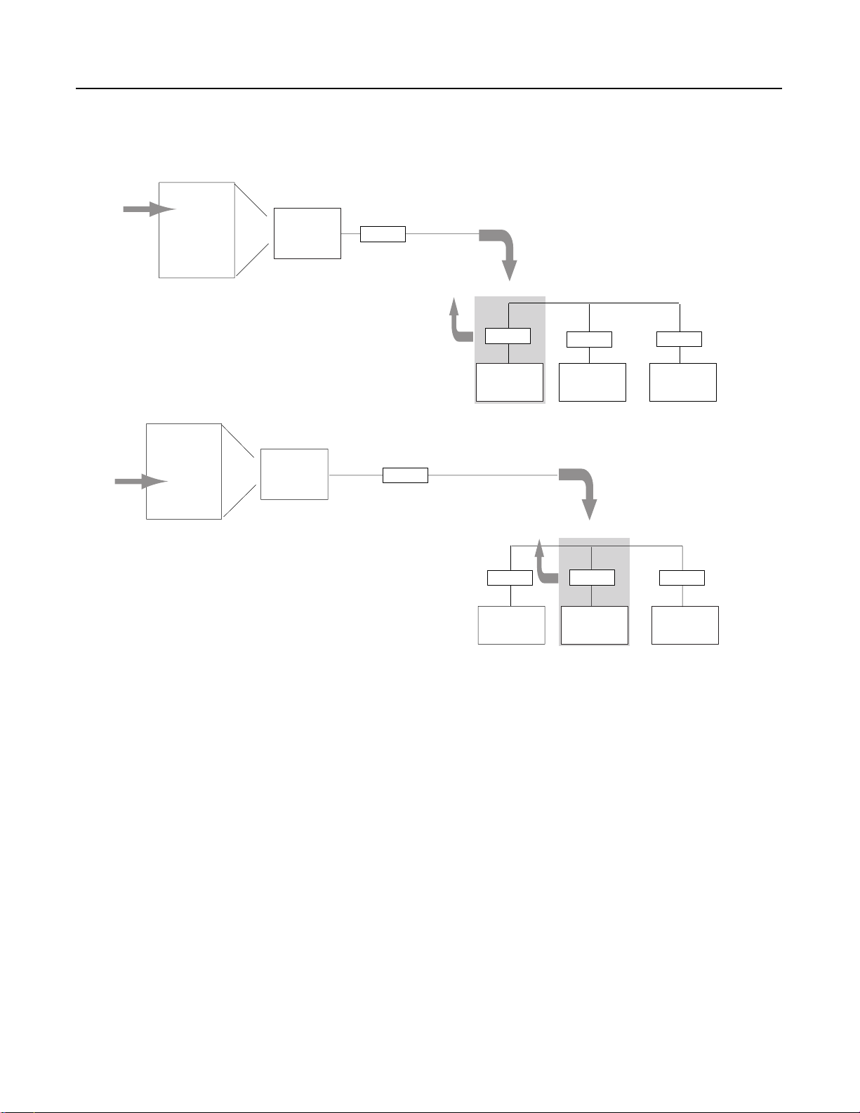
Figure 1.1
A master station polls the slave stations in the order the slave stations
appear on the list. slave stations send either a data packet or a packet
indicating that the station has no data to send.
Polling List
Stn 1
Stn 2
Master
Station
Modem
Stn 3
1. Master station polls a slave station for data.
Return Data
Packet or DLE
EOT to Master
Designing Communication 1-7
Poll to slave
2. If the slave station has data to send, then it
sends a data packet. If there is no data to
send then it sends an end of tr ansmission
packet (DLE EOT).
Polling List
Stn 1
Stn 2
Master
Station
Stn 3
3. Master station polls the next slave station
for data.
4. If the slave station has data to send, then it
sends a data packet. If there is no data to
send then it sends an end of transmission
packet (DLE EOT).
5. Master station continues to poll each slave
station in the polling list. When the end of
the list is reached, the master station then
moves back to the beginning of the list and
starts the polling sequence over again.
Modem
Modem
slave
station 1
Return Data
Packet or DLE
EOT to Master
Modem
slave
station 1
Modem
slave
station 2
Modem
slave
station 2
Poll to slave
Modem
slave
station 3
Modem
slave
station 3
41180
Publication AG-6.5.8 - October 1998

1-8 Designing Communication
When the master station is configured for standard-communication
mode, you do not need to program any master-station message
instructions to communi cate with sl ave stations. Communi cation with
slave stations occurs by the master station sending polling packets to
slave stations. You only need mess age instruct ions when you want the
master station to write data to or read data from a location within a
slave station’s data table.
To help you understand: See:
standard-communication mode Figure 1.2
how a master station requests data Figure 1.3
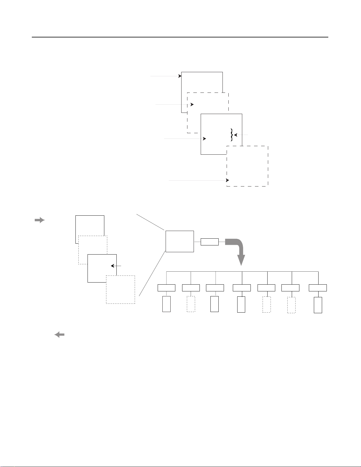
Figure 1.2
Use this machine state diagram to help you understand
communication
mode.
standard-
timeout received
and station active
and tries < or =
“DF1 message
retries”
MSG received and
multiple mode
forward data to
or return data
from data table
• Check for and send
outgoing MSG
• Select next station
to poll
timeout received and
station inactive
•Send poll
• Start ACK timeout
• Wait for EOT or MS G
(or timeout)
timeout received
and station active
and tries > “DF1
message retries”
make station
inactive
EOT received indicating no
MSG to send make station
active (if inactive)
MSG received and
single poll mode
forward data to or
return data from
data table
41181
Publication AG-6.5.8 - October 1998

Master data table
reply packet
received
return data
Figure 1.3
Use this machine state diagram to help you understand how a device
requests data transfer (read or write request) via DF1 half-duplex protocol.
ACK timeout received
and tries > “DF1
message retries”
return error indication
Designing Communication 1-9
• Ladder logic
triggers MSG
• Master driver
formats command
packet
ACK timeout received
and station active and
tries < or = “DF1
message retries”
• Send command
packet
• Start ACK t imer
• Wait for ACK (or
timeout)
application timeout
received return
error indicaton
• Start application
timer
• Resume polling
• Wait for reply (or
timeout)
To design a communication scheme using standard-communication
mode, you must do the following:
• design a polling scheme
• plan for timing issues
ACK received
41182
Publication AG-6.5.8 - October 1998

1-10 Designing Communication
Designing a Polling Scheme
Each master station in a SCADA application must have a polling
scheme configured. To design a polling scheme, do the following:
• choose the type of scheme best suited for your application
• optimize your polling scheme to obtain the best efficiency
The master station you are using determines the type of polling
choices you have; ho wever, A-B master stations of fer si milar ch oices,
such as:
• normal and priority polling lists
• ability to poll a slave sta tion:
– once per occurrence in the poll list (single)
– until it has no more messages to send (multiple)
Choosing Normal or Priority Polling Lists
slave stations listed in a pr iority poll list are polled more frequently
than those listed in the normal poll list. Place the slave stations that
you need information from more frequently in a priority poll list.
Within each poll list, slave stations are assigned a status, which is
either active or inactive. A slave station becomes inactive when it
does not respond to a master stati on’s poll packet after the co nfigur ed
number of retries.
If your master station is a Logix5550 or PLC-5, you can use
application logic to reorder the polling lists and priority while the
application logic is executing.
Figure 1.4 and Figure 1.5 show h ow normal and pri orit y list s rel ate to
one another.
Publication AG-6.5.8 - October 1998
Designing Communication 1-11
Figure 1.4
The master station scans slave stations in a set sequence.
1. Scans all stations in the active priority
poll file
2. Scans one station in the inactive priority
poll file
3. Scans stations in the active normal poll file
based on the normal poll group size, which
you specify during configuration. For example,
if the group size were 3, then three stations
would be polled in the normal file before the
master continues to the next step in the
sequence
4. Scans one station in the inactive normal poll file
after all stations in the active normal list have
been polled.
Active Priority
Poll List
STN1
STN7
Poll List
STN2
Inactive Priority
STN6
Poll List
Active Normal
STN3
STN4
Group size = 1
Active Priority
Poll List
Inactive Priority
Poll List
Active Normal
Poll List
aa
bb
cc
dd
Inactive Normal
Poll List
Figure 1.5
Here is how the polling sequence applies to an application.
Master
Station
Modem
41183
STN1
STN7
STN2
STN3
STN1
STN7
STN6
STN4
STN5
Inactive Normal
Beginning of new scan
Poll List
STN5
Modem
1
Modem
2
Modem
3
Modem
4
Modem
5
Modem
6
Modem
7Polling Sequen c e:
41184
Publication AG-6.5.8 - October 1998

1-12 Designing Communication
Choosing Single or Multiple Message Transfer
Depending on your application’s requirement, you can choose the
number of messages you want to receive from a slave station during
its turn.
If you want to receive: Choose:
only one message from a slave station per poll per a
station’s turn
Choose this method only if it is critical to keep the poll
list scan time to a minimum.
as many messages from the slave station as it has in
its queue
single transfer
multiple transfer
Planning for Timing Issues
Two types of timing categories exist:
• protocol timers, which sp ecify how long a master station will
wait to “he ar” from a slave station
• Request to send (RTS) timers, which you can use to make sure
the modem is ready to accept data or has passed on the data
Set and adjust these timing values as necessary for your application.
Set your RTS times based on the communication media and modem
you are using.
Design Considerations
• Define a polling list type to use (normal or priority).
• Define a station list.
• Use Figure 1.6 to help understand how the MSGs are handled
using standard communication.
Publication AG-6.5.8 - October 1998
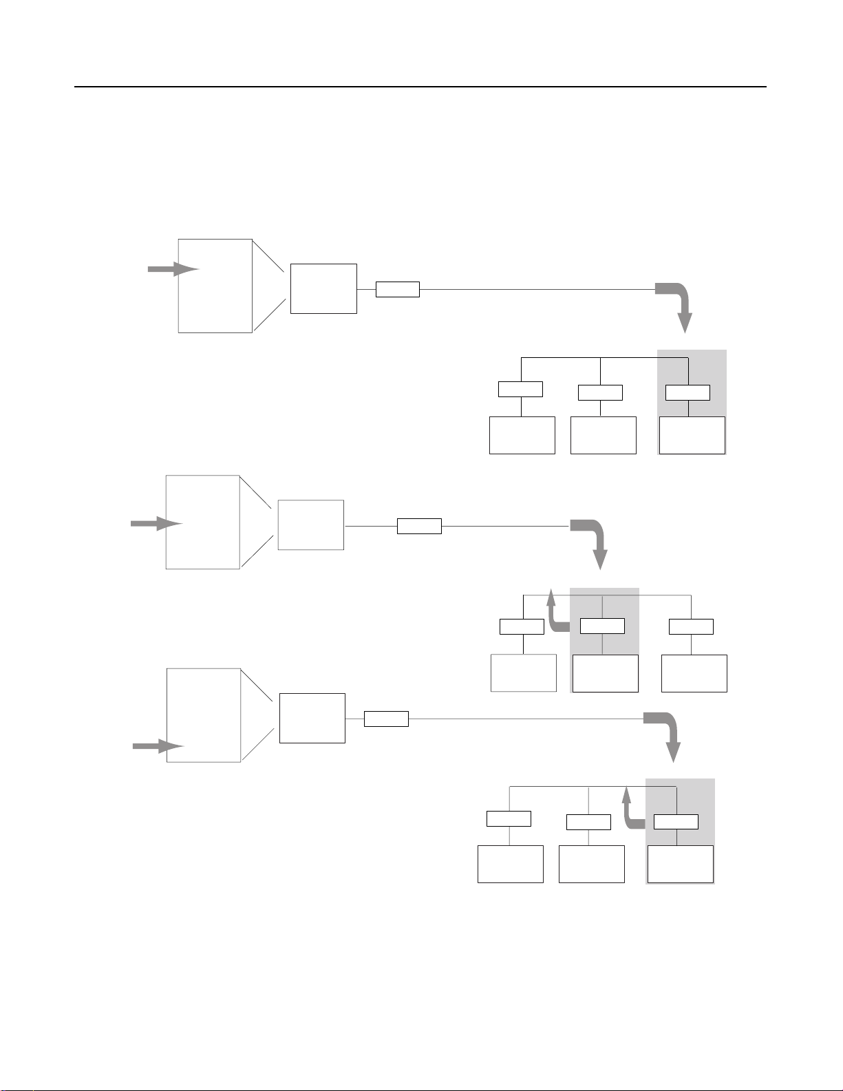
. Polled station 1; ready to poll station 2.
. MSG sent to station 3 (MSG was waiting in queue).
Polling List
Stn 1
Stn 2
Master
Station
Stn 3
Designing Communication 1-13
Figure 1.6
Use this figure to help you understand the effect sending MSGs has on
Logix5550, PLC-5 and SLC 500 polling.
MSG to slave
Modem
3. Master station continues polling where it left off in the polling
sequence, e.g., station 2.
Polling List
Stn 1
Master
Stn 2
Station
Stn 3
. Master station polls station 3.
. Station 3 replies with data.
Polling List
Stn 1
Stn 2
Master
Station
Modem
Stn 3
Modem
Modem
slave
station 1
Return Data
Packet or DLE
EOT to Master
Modem
slave
station 1
Modem
slave
station 2
Poll to slave
Modem
slave
station 2
Return Data
Packet to Master
Modem
slave
station 3
Modem
slave
station 3
Poll to slave
6. Master station returns to beginning of the poll list.
Modem
slave
station 1
Modem
slave
station 2
Modem
41185
station 3
slave
Publication AG-6.5.8 - October 1998
1-14 Designing Communication
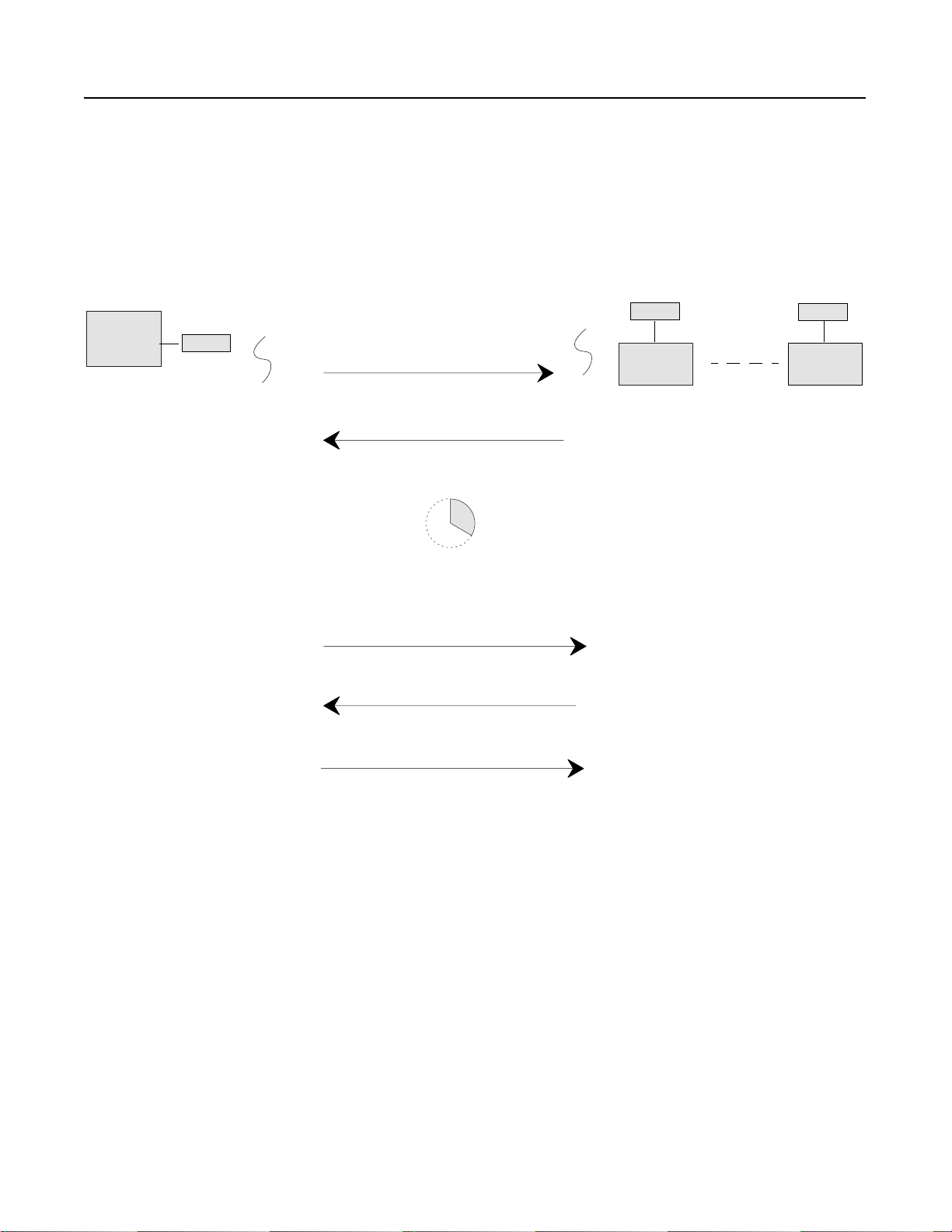
Communication Scheme Design Using Message-based Mode
1. Message (via MSG instruction) sent to
Master
Station
3. Master station waits a user-defined time “Reply
Message Wait” parameter before polling the
station for a reply.
Modem
a specific slave station. (eg., slave
station 1)
2. Slave station receives message and
sends an acknowledgment back (ACK)
In message-based communication mode, the master station sends
solicited messages (messages programmed via ladder logic) to a
specific slave station when the master requires information. In this
mode, the communication link is inactive until the master station has
a message to send to a slave station. Figure 1.7 explains the
communication sequence that occurs.
Figure 1.7
Use this figure to help you understand message-based communication.
Modem
Slave
Station 1
3. Slave station forms a reply message to the
master station’s enquiry.
Modem
Slave
Station 2
Designing Communication for Full-Duplex Protocol
4. Master station polls slave station for its reply
5. slave station sends its reply message
41186
6. Master station receives reply and sends an
acknowledgement back (ACK)
When designing communic at io n us ing DF1 full-duplex protocol, you
must specify some timers and counters that control the
communication betwee n a tran smitting st ation and a receiving station.
Consider the type of link media you are using to help you determine
the best values for the timer and counters. For example, you can
expect a message being sent over a satellite link to take longer than
one being sent over a te lephon e leas ed-li ne li nk. Figur e 1.8 shows th e
communication sequence for DF1 full-duplex protocol.
Publication AG-6.5.8 - October 1998

Data table
reply packet
received return data
Figure 1.8
Use this machine state diagram to help you understand a device requests
data transfer (read or write request) via DF1 full-duplex protocol.
NAK received and retries >
“NAK retries”
or
ACK timeout received and
tries > “ENQ retries”
return error indication
• Ladder logic
triggers MSG
• DF1 driver
formats
command
packet
• Send command
packet
• Start ACK timer
• Wait for ACK (or
timeout)
Designing Communication 1-15
NAK received and
retries < or = “NAK
retries”
or
ACK timeout received
and tries < or = “ENQ
retries” send enquiry
application timeout
received return error
indication
•Start
application
timer
•Wait for reply
(or timeout)
ACK received
41187
Publication AG-6.5.8 - October 1998

1-16 Designing Communication
What to Do Next? Make sure you:
• choose the communication method best suited for your
application
• make initial confi guration choices for the communicati on method
you have chosen
• use this chapter as a reference as you configure the devices in
your SCADA system
Publication AG-6.5.8 - October 1998
Chapter
Configuring Enhanced PLC-5 Processors
Use This Chapter... ... to help you set up an Enhanced PLC-5 processor as a master
station, as a slave station, or as a station on a point-to-point link.
For information about: See page:
an overview of the tasks required to configure a PLC-5 processor 2-1
installing the processor 2-2
configuring the processor as a DF1 half-duplex master station using
standard-communication mode
configuring the processor as a DF1 half-duplex master station using
message-based communication mode
configuring the processor as a slave station 2-13
configuring the processor as a station on a point-to-point link 2-16
the types of mes sages you can se nd from a PLC-5 processo r to an other
processor, how to configure the MSG instruction, and some
configuration characteristics
2-3
2-9
2-20
2
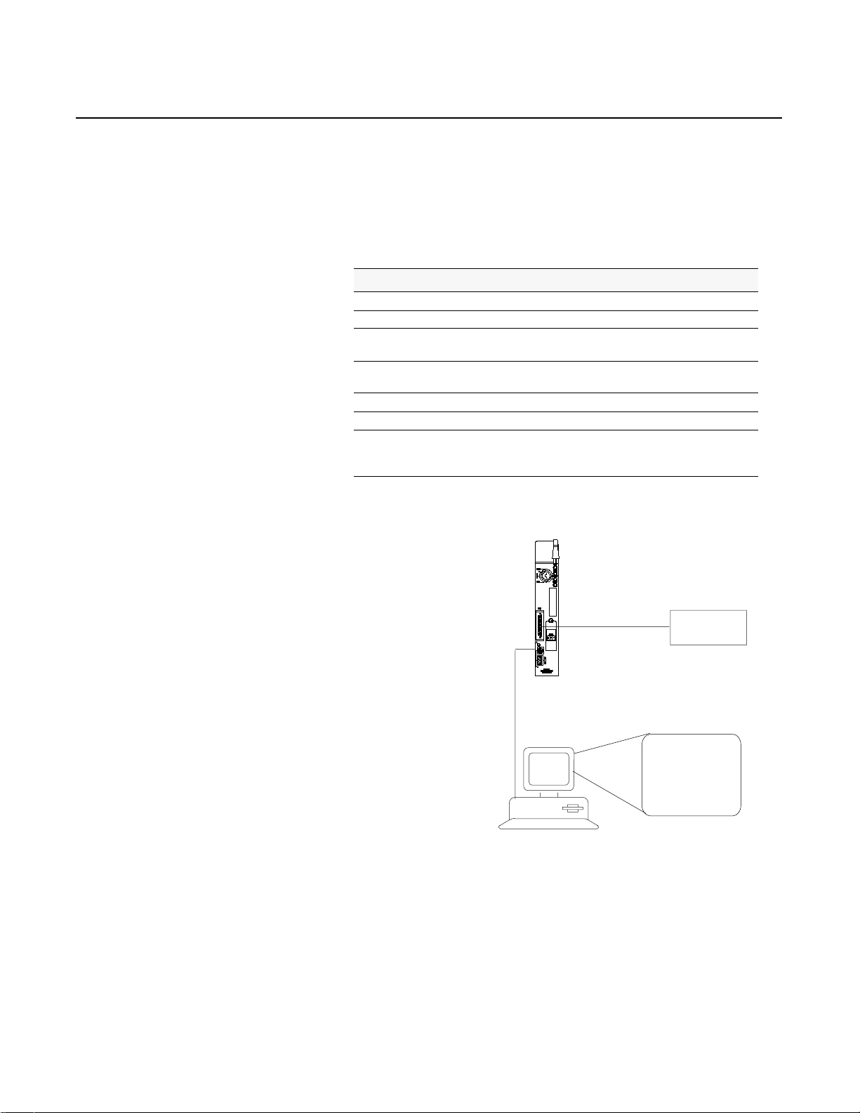
Overview To configure an Enhanced PLC-5 processor, perform these tasks:
3. Install and configure the modem
for communication with the
1. Install the processor; connect
the serial cable to channel 0.
2. Define the processor’s
communication characteristics
using your PLC-5 programming
software.
processor; connect the modem to
the processor’s serial channel.
Modem
PLC-5
programming
software
41188
Publication AG-6.5.8 - October 1998

2-2 Configuring Enhanced PLC-5 Processors
T
Installing the Processor Before install ing the p rocessor, set the processor s witch ass emblies.
Define: By setting switch assembly:
DH+ and DF1 point-to-point station address S1
RS-232 as the electrical interface for the serial port S2
For details about installing the processor, see the Enhanced PLC-5
Programmable Controllers Quick Start, publication 1785-10.4.
For cable pinouts, see Figure 2.1 or Appendix A-2.
Figure 2.1
Enhanced PLC-5 Serial Port Pin Assignments and S2 Settings.
25-pin male 25-pin 9-pin
C. GND 1 1 NC
TXD.OUT 2 2 3
RXD.IN 3 3 2
44 7
55 8
66 6
77 5
88 1
20 20 4
to modem
25-pin male cable connector
RTS.OUT
CTS.IN
DSR.IN
SIG.GND
DCD.IN
DTR.OUT
S2 (set for RS-232)
Bottom of processor
o Specify:
RS-232C
Publication AG-6.5.8 - October 1998
12345678910
ON ON ON OFF OFF ON ON OFF ON OFF
Set Switches:
Note: The DF1 Point-to-Point Station
Address of the processor is the same as
the DH+ address defined by S1
Toggle pushed
toward TOP
OFF
Toggle pushed
toward BOTTOM
ON
41189

Configuring Enhanced PLC-5 Proces sors 2-3
Configuring a DF1 Half-Duplex Standard Mode Master Station
Double-click on the Channel
Configuration file to bring up the
Edit Channel Configuration
interface.
Choose standard-communication mode if you want to query slave
stations for in formation bas ed upon user -config ured poll ing lists. This
mode is used most often in point-to-multipoint configurations
because it allows polled report-by-exception (page 1-4),
slave-to-slave messaging (page 1-5) and slave programming over the
telemetry network (chapt er 1 1) to be impl emented. In add ition, in th is
mode the master station maintains an active node table which allows
an MMI or programming terminal to immediately identify which
slave nodes can currently communicate and which nodes cannot.
To configure the processor for a master station using standard
communication, place the processor into program mode and do the
following using your RSLogix 5 software:
1. On the Channel 0 tab, choose
System (Master) for your
Communication Mode.
2. Configure the Serial Port,
Options, and Polling parameters
according to Table 2.A.
3. Configure Options parameters
according to Table 2.A .
Publication AG-6.5.8 - October 1998

2-4 Configuring Enhanced PLC-5 Processors
4. Configure the Polling parameters
according to Table 2.A.
5. When all parameters are set,
click OK.
6. Create station lists (page 2-7).
Define the Communication Driver Characteristics
Use Table 2.A to help you understand the c ommu nic at ion parameters
you need to specify on the Channel Configuration screen for
standard-communication mode.
Use Worksheet 2.1 (Appendix D-4) for an example confi gurati on and
to record your station’s configuration.
Table 2.A
Define these communication parameters for a PLC-5 master station using
standard-communication mode to talk to slave stations.
RSLogix 5 Tab: Parameter: Selections:
Channel 0 Diagnostic File Select an unused integer file to store channel status information. You must define a diagnostic file in
order to be able to view channel 0 status. See Table 2.B on page 2-6 for description of what is in this
file.
Remote Mode
Change
Mode Attention
Character
System Mode
Character
User Mode
Character
Serial Port Baud Rate Select a communication rate that all devices in your system support. Configure all devices in the
Bits Per Character Match the number of bits per character to the devices with which you are communicating
Stop Bits Match the number of stop bits to the devices with which you are communicating.
Control Line This parameter defines the mode in which the master driver operates. Choose a method appropriate
Check enable remote mode change if you want to switch the configuration of the channel during
runtime. Leave the parameter set at the default (unchecked) if you are not using this feature.
Select a ch ara cter th at will sig na l a r emot e mo de c han ge. Leav e the par amet er s et at the d ef ault i f yo u
are not using remote mode change.
Select a character that will signal the channel to switch into system mode. Leave the parameter set at
the default if you are not using remote mode change.
Select a character that will signal the channel to switch into user mode. Leave the parameter set at the
default if you are not using remote mode change.
system for the same communication rate.
for your system’s configuration:
• If you are not using a modem, choose NO HANDSHAKING.
• If the master modem is full duplex and the slave modem is full-duplex, choose FULL-DUPLEX
MODEM.
• If all the modems in the system are half-duplex, choose HALF-DUPLEX MODEM WITHOUT
CONTINUOUS CARRIER.
Publication AG-6.5.8 - October 1998

RSLogix 5 Tab: Parameter: Selections:
Configuring Enhanced PLC-5 Proces sors 2-5
Serial Port Error Detect With this selection, you choose how the processor checks the accuracy of each DF1 packet
transmission.
BCC: This algorithm provides a medium level of data security. It cannot detect:
• transposition of bytes during transmission of a packet
• the insertion or deletion of data values of zero within a packet
CRC: This algorithm provides a higher level of data security.
Select an error detection method that all devices in your system support.
When possible, choose CRC.
Options Station Address Define the octal address of the processor on the DF1 half-duplex link. Each station on a link must have
a unique address. Choose an address between 0 and 376
Station address 377
is the broadcast address, which you cannot select as a station’s individual
8
.
8
address.
DF1 Retries Defines the number of times a master station retries either a message before the master station
declares the message undeliverable, or poll packet to an active station before the master station
declares that station to now be inactive.
RTS Send Delay RTS send delay is the amount of time in 20 millisecond increments that elapses between the assertion
of the RTS signal and the beginning of the message transmission. This time allows the modem to
prepare to transmit the message.
The Clear to Send (CTS) signal must be high for transmission to occur.
RTS Off Delay RTS off delay is the amount of time in 20 millisecond increments that elapses between the end of the
message transmission and the de-assertion of the RTS signal. This time delay is a buffer to make sure
that the modem has transmitted the message but should normally be left at zero.
ACK Timeout Define the amount of time in 20 millisecond increments that you want the processor to wait for an
acknowledgment from a slave station to its transmitted message before the processor retries the
message or the message errors out.
Reply Message Wait Define the amount of time in 20 millisecond increments that the master station will wait after receiving
an ACK (to a master-initiated message) before polling the slave station for a reply.
Choose a time that is, at minimum, equal to the longest time that a slave station needs to format a
reply packet. This is typically the maximum scan time of the slave station
Note: This field is only valid if the polling mode field is configured to be MESSAGE BASED.
MSG Application
Timeout
Define the number of 30 second increments within which the reply message must be received before
the error bit is set on the message. The timer starts when the ACK is received.
Polling Polling Mode If you want to receive:
• only one message from a slave station per its turn, choose STANDARD (SINGLE MESSAGE
TRANSFER PER NODE SCAN)
Choose this method only if it is critical to keep the poll list scan time to a minimum.
• as many messages from a slave station as it has, choose STANDARD (MULTIPLE MESSAGE
TRANSFER PER NODE SCAN)
Master Message
Transmit
If you want the master station to:
• send all of the master station-initiated MSG instructions to the slave stations before polling the next
slave station in the poll list, choose Between Station Polls
This method makes certain that master station-initiated messages are sent in a timely and regular
manner (after every slave station poll).
• only send master station-initiated MSG instructions when the master’s station number appears in
the polling sequence; choose In Poll Sequence
With this method, sending master station-initiated messages are dependent upon where and how
often the master station appears in the poll list. To achieve the same goal as the Between Station
Polls method, the master-station’s address would have to appear after every slave-station’s
address.
Publication AG-6.5.8 - October 1998

2-6 Configuring Enhanced PLC-5 Processors
RSLogix 5 Tab: Parameter: Selections:
Polling Normal Poll Node
File
Normal Poll Group
Size
Priority Poll Node
File
Active Station File Enter an unused binary file that will store the status of all the stations in your network configuration.
To display Channel Status, double
click on Channel Status, which is
located within Channel
Configuration.
Enter an unused integer file that will store the addresses of the slave stations you want in the normal
poll list.
Enter the quantity of active stations located in the normal poll list that you want polled during a scan
through the normal poll list before returning to the priority poll list.
Enter an unused integer file that will store the addresses of the slave stations you want in the priority
poll list.
The file stores one station address per bit.
0 = inactive; 1 = active.
Displaying System (Master) Channel Status
To access the various channels
from the Channel status screen,
click on the tabs. Descriptions of
the status screen fields can be
found in Table 2.B.
Table 2.B Descriptions of System Mode DF1 Master Channel Status Fields
Status Field: Location Description
Clear Clear counters for all channels by clicking on Clear button
DCD Recover word 11 Displays the number o f tim es the pr o ces sor dete ct s t he DCD ha nd sh ak ing l ine ha s
gone low to high.
Lost Modem word 12 Displays the number of times that the modem lost bit (S:17/5) has gone low to
high.
Messages Sent word 1 Displays the number of messages sent by the processor (including message retry).
Publication AG-6.5.8 - October 1998

Configuring Enhanced PLC-5 Proces sors 2-7
Status Field: Location Description
Messages Received word 2 Displays the number of messages the processor received with no error.
Undelivered Messages word 3 Displays the number of messages that were sent by the processor but not received
Messages Retry word 4 Displays the number of messages resent.
Duplicate Mesages Received word 9 Displays the number of times the processor received a message packet identical to
EOT Received on First Poll word 8 Displays the number of times the Master received an EOT in response to the first
Bad Packet / No ACK word 7 Displays the number of incorrect data packets that the processor has received.
Last Normal Poll List Scan (100 ms) word 5 The time it took to complete the previous scan of the normal station poll list.
Max Normal Poll List Scan (100 ms) word 6 The maximum time taken to complete a scan of the normal station poll list.
Last Priority Poll List Scan (100 ms) word 10 The time it took to complete the previous scan of the priority station poll list.
Max Priority Poll List Scan (100 ms) word 13 The maximum time taken to complete a scan of the priority station poll list.
DTR (Data Terminal Read) word 0; bit 4 Displays the status of the DTR handshaking line (asserted by the processor).
DCD (Data Carrier Detect) word 0; bit 3 Displays the status of the DCD handshaking line (received by the processor).
DSR (Data Set Ready) word 0; bit 2 Displays the status of the DSR handshaking line (received by the processor).
RTS (Request to Send) word 0; bit 1 Displays the status of the RTS handshaking line (asserted by the processor).
CTS (Clear to Send) word 0; bit 0 Displays the status of the CTS handshaking line (received by the processor).
by the destination device.
the previous message packet.
poll of a station.
Create Station Lists
After defining your pol ling fi les an d group si ze, cre ate st ation list s by
entering the station address of each slave station into either the
normal poll file or priority poll file of the PLC-5 data table. Place
each station address in an individual word in a poll file (normal and
priority) starting at wo rd 2.
The normal and priority poll file layout is as follows:
This word in a poll file: Contains this information:
word 0 total number of stations to be polled (for a list)
word 1 the address location (poll offset) of the station currently
word 2 through word
being polled (as long as all configured stations are active)
For example: a value of 1 means the station address stored
in word 2 is being polled, 2 means the address stored in
word 3 is being polled, etc.
This word is automatically updated by the master station as
a new slave station is polled.
xx
the slave station address in the order that the stations
should be polled
Store one station address in each word.
Publication AG-6.5.8 - October 1998

2-8 Configuring Enhanced PLC-5 Processors
To place a station address in a poll file, do the following:
1. Access the PLC-5 data table.
2. Specify the address of the integer file that i s either the no rmal poll
3. Enter the station addresses of the slave stations you want in the
Important: PLC-5 station addresses are octal addresses. The poll
Figure 2.2 is an example of a station list containing three stations:
octal addresses 10, 3, and 12. Station 12 is being polled.
Figure 2.2
Example Station List
file or priority poll file (e.g., If the normal poll file is N11, then
you specify N11:0).
poll list starting at word 2. Put them in the order you want them
polled.
files are integer files. To properly enter PLC-5 station
addresses in a poll file, you must either:
•change the radix of the file to octal
•convert the PLC-5 octal station addresses to decimal
total number
of stations
pointer showing the
station address being
polled
address of first
station in list
address of second
station in list
address of third
station in list
Monitor Active Stations
T o see wha t stati ons are ac tive, vie w the acti ve station f ile. Each bit in
the file represents a station on the link. The stations are numbered in
order as a continuous bit-stream file starting with the first bit in the
first word (F igure 2.3).
Figure 2.3
Example Active Station File
Address 15 Data 0
B11:0 1111 1111 1111 1111 Remote station 0
B11:1 1111 1111 1111 1111 Remote station 16
B11:2 1111 1111 1111 1111
10
Publication AG-6.5.8 - October 1998

Configuring Enhanced PLC-5 Proces sors 2-9
For PLC-5 pro cessors, note the following:
Starting with these PLC-5 firmware revisions: This is what you will see:
Series E/Revision B
Series D/Revision C
Series C/Revision L
Series B/Revision M
Series A/Revision M
For all prior firmware revisions At power-up or after reconfiguration, the master station
Configuring a DF1 Half-Duplex Message-based Mode Master Station
At power-up or after reconfiguration, the master station
assumes that all slave stations are inactive (bit=0).
assumes that all slave stations are active (bit=1) and the
station displays inactive only after it fails to respond to a poll
packet.
Choose message-based commu nication mode i f you want to use MSG
instructions in user programming to communicate with one station at
a time. If your application uses satellite transmission or public
switched telephone network transmission, consider choosing
message-based. Communication to a slave station can be initiated on
an as-need ed basis.
Also choose message -based mode whe n a r edundant PLC-5 system is
being used as a master station. Connect both PLC-5 processor serial
ports to the master s ta ti on mode m through an RS-232 modem splitter
and precondition all MSG instructions with the Primary Processor
status bit.
With messa ge- based mode, you do not have an active station file that
you can use to monitor station status. Also, you cannot implement
slave-to-slave messaging or slave programming over the telemetry
network.
Publication AG-6.5.8 - October 1998

2-10 Configuring Enhanced PLC-5 Processors
To configure the processor for a master station using message-based
communication, place the processor in program mode and do the
following using RSLogix 5:
Double-click on the Channel
Configuration file to bring up the
Edit Channel Configuration
interface.
1. On the Channel 0 tab, choose
System (Master) for your
Communication Mode.
2. Configure the Serial Port,
Options, and Polling parameters
according to Table 2.C.
3. Configure Options parameters
according to Table 2.C.
4. Configure the Polling parameters
according to Table 2.C.
5. When all parameters are set,
click OK.
Publication AG-6.5.8 - October 1998

Configuring Enhanced PLC-5 Proces sors 2-11
Use Table 2.C to help you understand the communication para me te rs
you need to specify on the Channel Configuration screen.
Use Worksheet 2.2 (Appendix D-5) for an example confi gurati on and
to record your station’s configuration.
Table 2.C
Define these communication parameters for a PLC-5 master station using
message-based communication mode to talk to slave stations.
RSLogix 5 Tab: Parameter: Selections:
Channel 0 Diagnostic File Select an unused integer file to store channel status information. You must define a diagnostic
file in order to be able to view channel 0 status. See Table 2.B on page 2-6 for description of
what’s in this file.
Remote Mode Change Check enable remote mode change if you want to switch the configuration of the channel
during runtime. Leave the parameter set at the default (uncheck) if you are not using this
feature.
Mode Attention Character Select a character that will signal a remote mode change. Leave the parameter set at the
default if you are not using remote mode change.
System Mode Character Select a character that will signal the channel to switch into system mode. Leave the parameter
User Mode Character Select a character that will signal the channel to switch into user mode. Leave the parameter
Serial Port Baud Rate Select a communication rate that all devices in your system support. Configure all devices in the
Bits Per Character Match the numbers of bits per character to the devices with which you are communicating.
Stop Bits Match the number of stop bits to the devices with which you are communicating.
Serial Port Control Line This parameter defines the mode in which the master driver operates. Choose a method
Parity Parity provides additional message packet error detection. To implement even parity checking,
Error Detect With this selection, you choose how the processor checks the accuracy of each DF1 packet
set at the default if you are not using remote mode change.
set at the default if you are not using remote mode change.
system for the same communication rate.
appropriate for your system’s configuration:
• If you are not using a modem, choose NO HANDSHAKING.
• If the master modem is full duplex and the slave modem is full-duplex, choose FULL-DUPLEX
MODEM.
• If all the modems in the system are half-duplex, choose HALF-DUPLEX MODEM WITHOUT
CONTINUOUS CARRIER.
choose Even. To implement no parity checking, choose None.
transmission.
BCC: This algorithm provides a medium level of data security. It cannot detect:
• transposition of bytes during transmission of a packet
• the insertion or deletion of data values of zero within a packet
CRC: This algorithm provides a higher level of data security.
Select an error detection method that all devices in your system support.
When possible, choose CRC.
Publication AG-6.5.8 - October 1998

2-12 Configuring Enhanced PLC-5 Processors
RSLogix 5 Tab: Parameter: Selections:
Options Station Address Define the octal address of the processor on the DF1 half-duplex link. Each station on a link
must have a unique address. Choose an address between 0 and 376
.
8
Station addr ess 3 778 is the broadcast address, which you cannot select as a station’s individual
address.
DF1 Retries Define the number of times a master station retries either a message before the master station
declares the message undeliverable, or a poll packet to an active station before the master
station declares tht station to be inactive.
RTS Send Delay RTS send delay is the amount of time in 20 millisecond increments that elapses between the
assertion of the RTS signal and the beginning of the message transmission. This time allows the
modem to prepare to transmit the message. The Clear to Send (CTS) signal must be high for
transmission to occur.
RTS Off Delay RTS off delay is the amount of time in 20 millisecond increments that elapses between the end
of the message transmission and the de-assertion of the RTS signal. This time delay is a buffer
to ensure that the modem has transmitted the message but should normally be left at zero.
ACK Timeout Define the amount of time in 20 millisecond increments that you want the processor to wait for
an acknowledgment from a slave station to its transmitted message before retrying. This
timeout value is also used for the poll response timeout.
Reply Message Wait Define the amount of time in 20 millisecond increments that the master station will wait after
receiving an ACK (to a master-initiated message) before polling the slave station for a reply.
Choose a time that is, at minimum, equal to the longest time that a slave station needs to
format a reply packet. This is typically the maximum scan time of the slave station.
MSG Application Timeout The application timeout of the message is the number of 30 second increments within which
the reply message must be received before the error bit is set on the message. The timer starts
when the ACK is received.
Polling Polling Mode If you want to:
• accept unsolicited messages from slave stations, choose MESSAGE BASED (ALLOW SLAVE
TO INITIATE MESSAGES)
Slave station-initiated messages are acknowledged and processed after all master
station-initiated (solicited) messages.
Note: Slave stations can only send messages when they are polled. If the message-based
master st atio n n e ve r s en d s a slave station a messag e , t he m a st er st ati o n w i ll n e ve r s en d t he
slave station a poll. Therefore, to regularly obtain a slave station-initiated message from a
slave station, you should choose to use standard communications mode instead.
• ignore unsolicited messages from slave stations, choose MESSAGE BASED
(DO NOT ALLOW SLAVES TO INITIATE MESSAGES)
Slave station-initiated messages are acknowledged and discarded. The master station
acknowledges the slave station-initiated message so that the slave station removes the
message from its transmit queue, which allows the next packet slated for transmission into
the transmit queue.
Publication AG-6.5.8 - October 1998

Configuring Enhanced PLC-5 Proces sors 2-13
Configuring the Processor as a Slave Station
Double-click on the Channel
Configuration file to bring up the
Edit Channel Configuration
interface.
1. On the Channel 0 tab, choose
System (Slave) for your
Communication Mode
2. Configure the Serial Port
parameters according to
Table 2.D.
To configure the processor as a slave station, place the processor in
program mode and do the following using your programming
software:
3. Configure the Options
parameters according to
Table 2.D.
4. When all parameters are set,
click OK.
Use Table 2.D to help you understand the c ommu nic at ion parameters
you need to specify on the Channel Configuration screen.
Use Worksheet 2.3 (Appendix D-6) for an example confi gurati on and
to record your station’s configuration.
Publication AG-6.5.8 - October 1998

2-14 Configuring Enhanced PLC-5 Processors
Table 2.D
Define these communication parameters when configuring a PLC-5
slave station.
RSLogix 5 Tab: Parameter: Selections:
Channel 0 Diagnostic File Select an unused integer file to store channel status information. You must define a
Remote Mode Change
Enable
Mode Attention Character Select a character that will signal a remote mode change. Leave the parameter set at the
System Mode Character Select a character that will signal the channel to switch into system mode. Leave the
User Mode Character Select a character that will signal the channel to switch into user mode. Leave the
Serial Port Baud Rate Select a communication rate that all devices in your system support. Configure all devices
Bits Per Character Match the number of bits per character to the devices with which you are communicating.
Stop Bits Match the number of stop bits to the devices with which you are communicating.
Control Line This parameter defines the mode in which the slave station driver operates. Choose a
diagnostic file in order to be able to view channel 0 status. See Table 2.E on page 2-16 for
a description of what this file contains.
Check enable remote mode change if you want to switch the configuration of the channel
during runtime. Leave th e parame ter set at th e defaul t (unche cked ) if you are not using this
feature.
default if you are not using remote mode change.
parameter set at the default (unchecked) if you are not using remote mode change.
parameter set at the default if you are not using remote mode change.
in the system for the same communication rate.
method appropriate for your system’s configuration:
• If you are not using a modem, choose NO HANDSHAKING.
• If the master modem is full duplex and transmits a constant carrier and the slave
modem is half-duplex, choose HALF-DUPLEX MODEM WITH CONTINUOUS CARRIER.
• If all the modems in the system are half-duplex, choose HALF-DUPLEX MODEM
WITHOUT CONTINUOUS CARRIER.
Parity Parity provides additional message packet error detection. To implement even parity
checking, choose Even. To implement no parity checking, choose None.
Serial Port Error Detect With this selection, you choose how the processor checks the accuracy of each DF1 packet
Publication AG-6.5.8 - October 1998
transmission.
BCC: This algorithm provides a medium level of data security. It cannot detect:
• transposition of bytes during transmission of a packet
• the insertion or deletion of data values of zero within a packet
CRC: This algorithm provides a higher level of data security.
Select an error detection method that all devices in your system support.
When possible, choose CRC.

RSLogix 5 Tab: Parameter: Selections:
Configuring Enhanced PLC-5 Proces sors 2-15
Options Station Address Define the octal address of the the processor on the DF1 half-duplex link. Each station on a
link must have a unique address. Choose an address between 0 and 376
.
8
Station address 3778 is the broadcast address, which you cannot select as a station’s
individual address.
DF1 Retries The number of times a slave station retries a message before the slave station declares the
message undeliverable.
RTS Send Delay RTS send delay is the amount of time in 20 millisecond increments that elapses between
the assertion of the RTS signal and the beginning of the message transmission. This time
allows the modem to prepare to transmit the message.
The CTS (Clear-to-Send) signal must be high for transmission to occur.
RTS Off Delay RTS off delay is the amount of time in 20 millisecond increments that elapses between the
end of the message transmission and the de-assertion of the RTS signal. This time delay is
a buffer to make sure that the modem has transmitted the message but should normally be
left at zero.
ACK Timeout Define the amount of time in 20 millisecond increments that you want the processor to wait
for an acknowledgment from the master station to its transmitted message.
Detect Duplicate Messages Duplicate packet detection lets the PLC-5 processor detect if it has received a message
that is a duplicate of its most recent message from the master station. If you choose detect
duplicate mes sag es, the p roc es sor wi ll a ckn owl edge (AC K) th e me ss age b ut will no t a ct o n
it since it has already performed the message’s task when it received the command from
the first message.
If you want to detect du plicate pack ets and di scard them , check this par ameter. If you want
to accept duplicate packets and execute them, leave this parameter unchecked.
MSG Application Timeout Define the number of 30 second increments within which the reply message must be
received before the error bit is set on the message. The timer starts when the ACK is
received.
Publication AG-6.5.8 - October 1998

2-16 Configuring Enhanced PLC-5 Processors
Displaying Slave System Channel Status
To display Channel Status, double
click on Channel Status, which is
located within Channel
Configuration.
To access the various channels
from the Channel status screen,
click on the tabs. Descriptions of
the status screen fields can be
found in Table 2.E.
Table 2.E Descriptions of System Mode DF1 Slave Channel Status Fields
Status Field Diagnostic File Location Definition
DCD Recover word 11 The number of times the processor detects the DCD handshaking line has
Messages Sent word 1 The total number of DF1 messages sent by the processor (including message
Messages Received word 2 The number of messages received with no errors
Polling Received word 6 The number of master poll packets received by the processor
Received NAK word 5 The number of NAKs received by the processor
Lack of Memory/No ACK Sent word 8 The number of times the processor could not receive a message because it did
Lost Modem word 12 The number of times the lost modem bit has gone low to high
Messages Retry word 4 The number of message retries sent by the processor
Undelivered Messages word 3 The number of messages that were sent by the processor but not
Duplicate Messages Received word 9 The number of times the processor received a message packet identical to the
gone low to high
retries)
not have available memory
acknowledged by the destination device
previous message packet
Publication AG-6.5.8 - October 1998

Status Field Diagnostic File Location Definition
Configuring Enhanced PLC-5 Proces sors 2-17
Bad Packet/No ACK word 7 The number of incorrect data packets received by the processor for which a no
DTR (Data Terminal Ready) word 0;bit 4 The status of the DTR handshaking line (asserted by the processor)
DSR (Data Set Ready) word 0;bit 2 The status of the DSR handshaking line (received by the processor)
RTS (Request to Send) word 0;bit 1 The status of the RTS handshaking line (asserted by the processor)
CTS (Clear to Send) word 0;bit 0 The status of the CTS handshaking line (received by the processor)
DCD (Carrier Detect) word 0;bit 3 The status of the DCD handshaking line (received by the processor)
ACK was returned
Publication AG-6.5.8 - October 1998

2-18 Configuring Enhanced PLC-5 Processors
Configuring the Processor as a Station on a Point-to-Point Link
Double-click on the Channel
Configuration file to bring up the
Edit Channel Configuration
interface.
1. On the Channel 0 tab, choose
System (Point-to-Point) for your
Communication Mode.
2. Configure the Serial Port
parameters according to
Table 2.F.
To configure the processor as a station on a point-to-point link, place
the processor in program mode and do the following using your
programming software:
3. Configure the Options
parameters according to
Table 2.F.
4. When all parameters are set,
click OK.
Publication AG-6.5.8 - October 1998
Use Table 2.F to help you unders tan d t he screen parameters you need
to specify on the Channel Configuration screen.
Use Worksheet 2.4 (Appendix D-7) for an example confi gurati on and
to record your station’s configuration.
Table 2.F
Define these parameters when using the PLC-5 processor as a device on a
point-to-point link.

Configuring Enhanced PLC-5 Proces sors 2-19
RSLogix 5 Tab:
Channel 0 Diagnostic File Select an unused integer file that you want to use to store channel status information. You must
Serial Port Baud Rate Select a communication rate that all devices in your system support. Configure all devices in the
Parameter: Selections:
define a diagnostic file in order to be able to view channel 0 status. See Table 2.G on page 2-20 for
a description of what this file contains
Remote Mode Change Enable remote mode change if you want to switch the configuration of the channel during runtime.
Leave the parameter set at the default if you are not using remote mode change.
Mode Attention Character Select a character that will signal a remote mode change. Leave the parameter set at the default if
you are not using remote mode change.
System Mode Character Select a character that will signal the channel to switch into system mode. Leave the parameter
set at the default if you are not using remote mode change.
User Mode Character Select a character that will signal the channel to switch into user mode. Leave the parameter set
at the default if you are not using remote mode change.
system for the same communication rate.
Bits Per Character Match the number of bits per character to the device with which you are communicating.
Stop Bits Match the number of stop bits to the device with which you are communicating.
Control Line This parameter defines the mode in which the driver operates. Choose a method appropriate for
your system’s configuration:
• If you are not using a modem, choose NO HANDSHAKING.
• If you are using a full-duplex modem, choose FULL-DUPLEX.
Parity Parity provides additional message packet error detection. To implement even parity checking,
choose Even. To implement no parity checking, choose None.
Options NAK Receive Define the number of NAKs the processor can receive in response to a transmitted message before
DF1 ENQs Define the number of enquiries (ENQs) that you want the processor to send after an ACK timeout
ACK Timeout Define the amount of time in 20 millisecond increments you want the processor to wait for an
Options Detect Duplicate
Messages
MSG Application Timeout Define the number of 30 second increments within which the reply message must be received
Error Detect With this selection you choose how the processor checks the accuracy of each DF1 packet
the station declares the message undeliverable.
occurs before the station declares the message undeliverable.
acknowledgment from a station to its transmitted message.
Duplicate Packet Detection lets the PLC-5 processor detect if it has received a message that is a
duplicate of its most recent message from another station. If you choose detect duplicate
messages, the processor will acknowledge (ACK) the message but will not act on it since it has
already performed the message’s task when it received the command from the first message.
If you want to detect duplicate packets and discard them, check this parameter. If you want to
accept duplicate packets, and execute them, leave this parameter unchecked.
before the error bit is set on the message. The timer starts when the ladder program first initiates
the message and is restarted if/when the ACK is received.
transmission.
BCC: This algorithm provides a medium level of data security. It cannot detect:
• transposition of bytes during transmission of a packet
• the insertion or deletion of data values of zero within a packet
CRC: This algorithm provides a higher level of data security.
Select an error detection method that all devices in your system support.
When possible, choose CRC.
Important: The station address in the point-to-point driver is determined by the DH+ address defined by switch assembly S1.
Publication AG-6.5.8 - October 1998

2-20 Configuring Enhanced PLC-5 Processors
Displaying Point-to-Point System Channel Status
To display Channel Status, double
click on Channel Status, which is
located within Channel
Configuration.
To access the various channels
from the Channel status screen,
click on the tabs. Descriptions of
the status screen fields can be
found in Table 2.G.
Table 2.G Descriptions of System (Point-to-Point) Channel Status Fields
Status Field Diagnostic File Location Definition
DCD Recover word 11 The number of times the processor detects the DCD handshaking line has
Messages Sent word 1 The total number of DF1 messages sent by the processor (including message
Messages Received word 2 The number of messages received with no errors
Inquiry Received word 6 The number of master poll packets received by the processor
Received NAK word 5 The number of NAKs received by the processor
Lack of Memory/Sent NAK word 8 The number of times the processor could no t receive a message be cause it did
Lost Modem word 12 The number of times the lost modem bit has gone low to high
Undelivered Messages word 3 The number of messages that were sent by the processor but not
Duplicate Messages Received word 9 The number of times the processor received a message packet identical to the
Inquiry Sent word 4 The number of ENQs sent by the processor
gone low to high
retries)
not have available memory
acknowledged by the destination device
previous message packet
Publication AG-6.5.8 - October 1998

Status Field Diagnostic File Location Definition
Configuring Enhanced PLC-5 Proces sors 2-21
Bad Packet/No ACK word 7 The number of incorrect data packets received by the processor for which a
DTR (Data Terminal Ready) word 0;bit 4 The status of the DTR handshaking line (asserted by the processor)
DSR (Data Set Ready) word 0;bit 2 The status of the DSR handshaking line (received by the processor)
RTS (Request to Send) word 0;bit 1 The status of the RTS handshaking line (asserted by the processor)
CTS (Clear to Send) word 0;bit 0 The status of the CTS handshaking line (received by the processor)
DCD (Carrier Detect) word 0;bit 3 The status of the DCD handshaking line (received by the processor)
NAK was returned
Messaging Messaging can occur between:
• a master station and a slave station
• a slave station and its master station
(See “Polled Report-by-Exception”)
• slave stations or between two processors connected via a
point-to-point li nk
For: See Page:
examples 2-21
list of considerations 2-23
Master Station to Slave Station
A PLC-5 master station communi cates with t he slav e stat ions t hat ar e
connected to it via modems in a point-to-multipoint configuration. A
master station send s a slav e stati on messages to rece ive status or issue
commands. For sample messaging ladder logic, see Appendix E-8.
Polled Report-by-Exception
Slave stations can gather information from the I/O points they are
responsible for and can send any anomalous readings to the master
station. To do this, write ladder logic in the slave station to monitor
certain conditions and send the data in a MSG instruction to the
master station. Figure 2.5 i s an exa mp le MSG instruct ion and control
block that a PLC-5 processor in a slave station can send to a PLC-5
master station. For sample messsaging ladder logic when using a
PLC-5 as a slave, see Appendix E-12.
Publication AG-6.5.8 - October 1998

2-22 Configuring Enhanced PLC-5 Processors
Processor-to-Processor
A processor-to-processor message can be two types:
• In a point-to-multipoint configuration, the messaging would be
between slave st ations; th e master st ation au tomatically routes the
message.
Master
Station
MSG from Slave
Station 1 to
Slave Station 2
Modem
Modem
Slave
Station 1
Master Station
routes MSG to
Slave Station 2
Modem
Slave
Station 2
• In a point-to-point configuration, the messaging would be
between the two connected peer devices.
MSG
Modem
Station 1
Modem
Station 2
The configuration of the network (point-to-multipoint vs. point-topoint) and the configuration of the station (master, slave, or peer)
does not af fect how you c onfig ure a MSG ins truct ion. Th at i s, a MSG
instruction being sent be tween two PLC-5 slave stat ions is configured
the same as a MSG instruction between two PLC-5 processors
connected point-to-point, which is configured the same as a MSG
instruction between a PLC-5 master st ation and a PLC- 5 slave statio n.
See Figure 2.4 through Figure 2.7 for example MSG control blocks.
Publication AG-6.5.8 - October 1998

Configuring Enhanced PLC-5 Proces sors 2-23
Considerations When Configuring MSG Control Blocks
Keep these considerations in mind when configuring messages
between a PLC-5 and SLC 500 or MicroLogix 1000 processors.
The following table lists which PLC-5 processors (series and
revision) you can use with the MSG instruction to transfer data
from/to a PLC-5 processor to/from any SLC 500 processor or
MicroLogix 1000 in SLC native mode.
Processor
Series/Revision:
Series A / revision M PLC-5/40, -5/40L, -5,60, -5/60L
Series A / revision J PLC-5/30
Series A / revision H PLC-5/11, -5/20
Series B / revision J PLC-5/40, -5/40L, -5/60, -5/60L
Series C / revision G PLC-5/11, -5/20, -5/20E, -5/30, -5/40, -5/40L, -5/V40,
-5/V40L, -5/40E, -5/60, -5/60L, -5/80, -5/80E, -5/V80,
-5/20C, -5/40C, -5/80C
Series D / all PLC-5/11, -5/20, -5/20E, -5/30, -5/40, -5/40L, -5/V40,
-5/V40L, -5/40E, -5/60, -5/60L, -5/80, -5/80E, -5/V80,
-5/20C, -5/40C, -5/80C
Series E / all PLC-5/11, -5/20, -5/20E, -5/30, -5/40, -5/40L, -5/V40,
-5/V40L, -5/40E, -5/60, -5/60L, -5/80, -5/80E, -5/V80,
-5/20C, -5/40C, -5/80C
Processors:
• Since all SLC 5/05, 5/04 and 5/03 processors with operating
system 301 or higher can respond to (and initiate) PLC-5 native
mode message commands, al l PLC- 5 proce ssors can t ransfer data
between their data tables and the data table of these particular
SLC processors (except fo r the I/O image table) as if they we re
messaging with another PLC-5 processor.
• In a single instruction, the maximum amount of words you can
read from or write to through channel 0 is as follows:
• SLC 500, 5/01, 5/02, and MicroLogix 1000 processor, 41
words
• SLC 5/03, 5/04, and 5/05 processor, 103 words
When configuring messages between a PLC-5 and Logix5550
processor , use the PLC-5 typed read and write commands and e nclose
the name of the Logix5550 tag in doub le quotes. Thi s is calle d logical
ASCII addressing.
Publication AG-6.5.8 - October 1998

2-24 Configuring Enhanced PLC-5 Processors
Example MSG Control Blocks
Application: See: Page:
PLC-5 read message to another PLC-5 processor Figure 2.4 2-24
PLC-5 write message to another PLC-5 processor Figure 2.5 2-25
Ladder Rung
Control Block
PLC-5 read message to a SLC 500 or MicroLogix 1000
processor
PLC-5 write message to a SLC 500 or MicroLogix 1000
processor
Figure 2.4
This is an example of a PLC-5 read MSG to another PLC-5
(or SLC 5/03, 5/04, 5/05, or Logix5550) processor.
Figure 2.6 2-26
Figure 2.7 2-27
MSG being sent to anoth er
PLC-5 processor.
MSG being sent out channel 0
(must use MG file type).
If the destination were a
Logix5550 processor, then
the address could also be
entered as “tagname”.
This MSG example tells this (master) PLC-5 to read the information from PLC-5 (slave) station 13
information in file N19:0 (master).
Publication AG-6.5.8 - October 1998
’s, location N7:0 and place the
8

Ladder Rung
Control Block
MSG being sent to anot her
PLC-5 processor.
Configuring Enhanced PLC-5 Proces sors 2-25
Figure 2.5
This is an example of a PLC-5 write MSG to another PLC-5
(or SLC 5/03, 5/04, 5/05, or Logix5550) processor.
MSG being sent out channel 0
(must use MG file type).
If the destination were a
Logix5550 processor, then
the address could also be
entered as “tagname”.
This MSG example tells this (master) PLC-5 to write the information from its file N19:0 through its serial port (channel 0) to the PLC-5
(slave) station 13
. The data’s destination is N7:0 of the PLC-5 (slave) station.
8
Publication AG-6.5.8 - October 1998

2-26 Configuring Enhanced PLC-5 Processors
Figure 2.6
This is an example of a PLC-5 read MSG
to a SLC 500 processor.
Ladder Rung
Control Block
MSG being sent to an SLC
500 or MicroLogix 1000
processor.
MSG being sent out channel 0
(must use MG file type).
This MSG example tells this PLC-5 (master) to read the information from SLC 500 (slave) 13
its N15:0 file.
(158) S:1 and place the information in
10
Publication AG-6.5.8 - October 1998

Ladder Rung
Control Block
MSG being sent to an S L C
500 or MicroLogix 1000
processor.
Configuring Enhanced PLC-5 Proces sors 2-27
Figure 2.7
This is an example of a PLC-5 Write MSG
to a SLC 500 processor.
MSG being sent out channel 0
(must use MG file type).
This MSG example tells the PLC-5 master station to write the information from its N15:1 through its serial port (channel 0) to the SLC
500 slave station 13
(158). The data’s destination is N7:0 of the SLC 500 slave station.
10
Publication AG-6.5.8 - October 1998

2-28 Configuring Enhanced PLC-5 Processors
Notes
Publication AG-6.5.8 - October 1998

Chapter
3
Configuring Classic PLC-5 Processors
with 1785-KE Modules
Use This Chapter. .. ... to help you set up a Classic PLC-5 processor, with the 1785-KE
Data Highway Plus™ Communicati on I nt erf ac e Mo dul e, as a remot e
station.
For information about: See page:
an overview of the tasks required to configure a Classic PLC-5
processor as a remote station
installing the processor 3-2
configuring and installing the 1785-KE module 3-3
connecting the processor and the 1785-KE module 3-4
the types of messages you can send from a Classic PLC-5
processor; how to configure the MSG instruction and some
configuration considerations
Overview To configure a Classic PLC-5 remote station, perform these tasks:
3-1
3-5
1. Install the processor
4. Install and configure the modem for
communication with the 1785-KE module; connect
the modem to the 1785-KE module’s serial channel.
See
modem
2. Configure and install the 1785-KE module
3. Connect the processor and the 1785-KE module
41194
Publication AG-6.5.8 - October 1998

3-2 Configuring Classic PLC-5 Processors with 1785-KE Modules
Installing the Processor Before installing the processor, set the switch assemblies.
Specify: By setting switch assembly:
DH+ station address of the processor
scanner as the processor mode
terminating resistors for remote I/O and DH+ links SW3
For more information:
About: See:
setting switches 1785 PLC-5 Family Programmable
Controllers Hardware Installation Manual,
publication 1785-6.6.1
installing the processor 1785 PLC-5 Family Programmable
Controllers Hardware Installation Manual,
publication 1785-6.6.1
Top View of Module Bottom View of Module
SW1
P
R
O
G
Set switches to define:
• the station address
• scanner as the mode
of operation
Switch Assembly SW1
Switch Assembly SW3
See the 1785 PLC-5 Family Programmable Controllers Hardware Installation Manual, publication
1785-6.6.1, for the settings.
Set switches for
terminating resistors
Publication AG-6.5.8 - October 1998

Configuring Classic PLC-5 Processors with 1785-KE Modules 3-3
Configuring and Installing the 1785-KE Module
Configure each 1785-KE being used with a Classic PLC-5 processor
in the network according to the following:
Configuration Selections Switch Settings
For: Choose: Set switch To:
Switch Assembly SW1 Protocol half-duplex 1 on
Error check CRC 2 on
Parity none 3 on
Embedded responses no 4 on
Duplicate message ignore 5 on
Handshaking signals use 6 on
Diagnostic command execute
Switch Assembly SW2 Station address
When the module is in
remote mode, do not poll
this address.
7
(Set all 1785-KE
modules for the same
address (if on different
DH+s). The address
should be one that is
not used by any remote
station.)
7 in this example
10
2on
3on
4on
5on
6off
7off
8off
Switch Assembly SW3 DH+
Communication Rate
RS-232
Communication Rate
Addressing mode remote 6 off
Switch Assembly SW4 Reserved 1-4 off
57.6 K 1 on
9600
(must match the
modem’s rate)
9600 in this example
2on
3off
4on
5on
Record your configurations on Worksheet 3.1 (page 9-9).
You can reconfigure the module’s parameters if additional
requirements are necessary.
Publication AG-6.5.8 - October 1998

3-4 Configuring Classic PLC-5 Processors with 1785-KE Modules
For more information about: See:
Connecting the Processor and 1785-KE Module
P
R
O
G
1785-KE
COMM
CONTROL
DH+
setting switches
installing the module
1785-KE DH+ Communications
Interface Module User Manual,
publication 1785-6.5.2
module to modem cable Connecting the Processor and 1785-KE
Module (page 3-4)
appendix A
The processor and 1785-KE module communicate with each other
over a DH+ link. Use a length of Belden 9463 cable to connect the
processor and the 1785-KE module.
15-pin male
C. GND 1
TXD.OUT 2
RXD.IN 3
RTS.OUT 4
CTS.IN 5
DSR.IN 6
SIG.GND 7
DCD.IN 8
DTR.OUT 11
25-pin male
1
2
3
4
5
6
7
8
20
DH+ connection via
Belden 9463 cable
DH+
RS-232
to modem
Publication AG-6.5.8 - October 1998

Configuring Classic PLC-5 Processors with 1785-KE Modules 3-5
Messaging Messaging can occur between:
• a remote station and its master station
(See “Polled Report-by-Exception”)
• remote stations or between two processors connected via a
point-to-point li nk
Polled Report-by-Exception
Remote stations can gather information from the I/O points they are
For: See page:
list of considerations 3-6
examples 3-6
responsible for and send any anomalous readings to the master
station. To do this, write logic in the remote station’s processor to
monitor certain conditions and send the data in a MSG instruction to
the master station. Figure 3.2 is an example MSG instruction and
control block that a Classic PLC-5 processor in a remote station can
send to a PLC-5 master station.
Processor-to-Processor
A processor-to-processor message can be two types:
• In a point-to-multipoint configuration, the messaging is between
remote stations; the master station routes the message.
Master
Station
MSG from Remote
Station 1 to Remote
Station 2
modem
modem
Remote
Station 1
Master Station rout es
MSG to Remote
Station 2
modem
Remote
Station 2
• In a point-to-point configuration, the messaging would be
between the two devices connected together.
MSG
modem
Station 1
modem
Station 2
The 1785-KE module acts as bridge between the Classic PLC-5
processor and the other stations on the telemetry network. Generally,
use remote MSGs to read data from and write data to another
processor.
Publication AG-6.5.8 - October 1998

3-6 Configuring Classic PLC-5 Processors with 1785-KE Modules
Considerations When Configuring MSG Control Blocks
Keep these considerations in mind when configuring messages
between a Classic PLC-5 and a SLC 5/02, 5/03, 5/04 or 5/05
processor.
• If you are sending mess ages betwee n a PLC-5 pro cessor and SLC
5/02 processor, then set S:2/8 in the SLC 5/02 status file to 1.
This bit is the CIF (Common Interface File) Addressing Mode
selection bit and lets the SLC 5/02 processor accept
“byte-offsets” from a PLC-5 processor.
• You cannot access words 0-7
-7110) in a SLC 5/02 C ommon Interface File from a PL C-5
(64
10
or directly access 1008-1078
processor.
• Since all SLC 5/04 and 5/05 processors and SLC 5/03 processors
with operating system 301 or higher can respond to (and initiate)
PLC-5 native mode message commands, all PLC-5 processors
can transfer data between their data tables and the data table of
these particular SLC processors (except for the I/O image table)
as if they were messaging with another PLC-5 processor.
• In a single instruction, the maximum amount of words you can
read from or write to as fo llows:
– SLC 5/02 processor: 41 words
– SLC 5/03, 5/04, 5/05 processor: 103 words
Example MSG Control Blocks
Application: See: Page:
Classic PLC-5 read message to another PLC-5 processor Figure 3.1 3-8
Classic PLC-5 write message to another PLC-5 processor Figure 3.2 3-9
Classic PLC-5 read message to a SLC 5/02 processor Figure 3.3 3-10
Classic PLC-5 write message to a SLC 5/02 processor Figure 3.4 3-11
Publication AG-6.5.8 - October 1998

ladder rung
setup screen (remote message)
Configuring Classic PLC-5 Processors with 1785-KE Modules 3-7
Figure 3.1
This is an example of a Classic PLC-5 read MSG to another
PLC-5 processor.
MSG being sent to
a PLC-5 processor
address of the
1785-KE module
address of the
target processor
This MSG example tells the Classic PLC-5 remote station to read the information from the PLC-5 master station’s (13
place the information in remote station file N19:0.
.) S:23 and
8
Publication AG-6.5.8 - October 1998

3-8 Configuring Classic PLC-5 Processors with 1785-KE Modules
Figure 3.2
This is an example of a Classic PLC-5 write MSG to another PLC-5
processor.
ladder rung
setup screen (remote message)
MSG being sent to
a PLC-5 processor
address of the
1785-KE module
address of the
target processor
This MSG example tells the Classic PLC-5 remote station to write the information from its S:23 to PLC-5 master station (13
N19:0.
.) file
8
Publication AG-6.5.8 - October 1998

ladder rung
setup screen (remote message)
MSG being sent to a
PLC-2-like device
Configuring Classic PLC-5 Processors with 1785-KE Modules 3-9
Figure 3.3
This is an example of a Classic PLC-5 read MSG to a
SLC 5/02 processor.
Word offset (in octal)
of SLC 500 file N9
Address of the
1785-KE module
Enter octal equivalent of
the SLC 500 decimal
station address
This MSG example tells the Classic PLC-5 processor to read the information from SLC 500 remote station 13
interface file N9, offset 77
(6310) and place the information in its N15:0 file.
8
(158) common
10
Set S:2/8 in SLC 5/02 status file to 1. This bit is the Common Interface File (CIF) Addressing Mode selection bit that allows the SLC
5/02 processor to accept “byte-offsets” from a PLC-5 processor.
Publication AG-6.5.8 - October 1998

3-10 Configuring Classic PLC-5 Processors with 1785-KE Modules
Figure 3.4
This is an example of a Classic PLC-5 wr ite MSG to a SLC 5/ 02 pr oce ssor.
ladder rung
setup screen (remote message)
MSG being sent to a
PLC-2-like device
Word offset (in octal)
of SLC 500 file N9
Address of the
1785-KE module
Enter octal equivalent of
the SLC 500 decimal
station address
This MSG example tells the Classic PLC-5 processor to write th e information from its N15:0 to SLC 500 remot e station 13
The information is to be written to offset 77
(6310) in the SLC common interface file N9.
8
(158).,
10
Set S:2/8 in SLC 5/02 status file to 1. This bit is the Common Interface File (CIF) Addressing Mode selection bit that allows the SLC
5/02 processor to accept “byte-offsets” from a PLC-5 processor.
Publication AG-6.5.8 - October 1998

Chapter
4
Configuring SLC 5/03, 5/04, and 5/05
Processors
Use This Chapter... ...to help you set up a SLC 5/03, 5/04, or 5/05 processor as a master
station, as a slave station, or as a station on a point-to-point link.
For information about: See page:
an overview of the tasks required to configure a SLC 5/03, 5/04, or 5/05
processor
installing the processor 4-2
configuring the processor as a DF1 half-duplex master station using standard
communication
configuring the processor as a DF1 half-duplex master station using
message-based communication
configuring the processor as a slave station 4-17
configuring the processor for point-to-point communication 4-20
the types of messages you can send from a SLC 5/03, 5/04, or 5/05
processor to another processor; how to configure the MSG instruction and
some configuration characteristics
4-1
4-7
4-14
4-23
Overview To configure a SLC 5/03, 5/04, or 5/05 processor, perform these
tasks:
1. Install the processor; connect the serial cable to channel 0.
modem
2. Define the processor’s communication characteristics using
RSLogix 500 programming software.
RSLogix 500
programming
software
3. Install and configure the modem for
communication with the processor; connect
the modem to the processor’s serial channel.
41190
Publication AG-6.5.8 - October 1998

4-2 Configuring SLC 5/03, 5/04, and 5/05 Processors
Installing the Processor For details about installing the processor into an I/O chassis, see the
SLC 500 Modular Hardware S tyle Inst allation a nd Operation Man ual,
publication 1747-6.2. Cable pinouts are shown in each example
configuration as well as in Appendix A.
9-pin female 25-pin 9-pin
DCD.IN 1 8 1
RXD.IN 2 3 2
SLC 5/03CPU
RUN
FORCE
FLT
DH485
BATT RS232
RUN REM PROG
9-pin female cable connector
TXD.OUT 3 2 3
DTR.OUT
SIG.GND
DSR.IN
RTS.OUT
CTS.IN
420 4
57 5
66 6
74 7
85 8
to modem
Using Modems that Support DF1 Communication Protocols
41191
The types of modems that you can use with SLC processors include
dial-up phone modems, leased-line modems, radio modems and line
drivers. For point-to-point full-duplex modem connections, use DF1
full-duplex protocol . For point -to-multipoint modem connecti ons, use
DF1 half-duplex master and slave protocols. In this case, one (and
only one) of the other devices must be configured for DF1
half-duplex master protocol.
Important: Do not attempt to use DH-485 protocol through
modems under any circumstance.
Dial-up Phone Modems
Dial-up phone line modems support point-to-point full-duplex
communications. Normally, an SLC processor on the initiating or
receiving end of the dial-up connection, will be configured for DF1
full-duplex protocol with the control line parameter set for
“Full-Duplex Modem.” See page 4-4 for details on the operation of
the RS-232 modem control signals when “Full-Duplex Modem” is
selected. See chapter 1 1 for further detai ls on using SLC process ors in
dial-up modem applications.
Publication AG-6.5.8 - October 1998

Configuring SLC 5/03, 5/04, and 5/05 Processors 4-3
When an SLC processor is the initia tor of the dial-up connection, use
one of the ASCII write instructions to send out the “AT” dial-up
string (for example ATDT 555-1212). The status file modem lost bit
(S:5/14) provides the feedback that the connection has been
successfully made. To hang up the connection, use the ASCII AHL
instruction to temporarily lo wer the DTR signal.
Leased-Line Modems
Leased-line modems are used with dedicated phone lines that are
typically leased from the local phone company. The dedicated lines
may be point-to-point topology supporting full-duplex
communications between two modems or in a point-to-multipoint
topology supporting half-duplex communications between three or
more modems. In the point-to-point topology, configure the SLC
processor for DF1 full-duplex protocol with the control line
parameter set to “Full-Duplex Modem.” In the point-to-multipoint
topology, configure the SLC processors for DF1 half-duplex master
or slave protocol with the control parameter set to “Half-Duplex
Modem without Continuous Carrier.” See page 4-5 for details on the
operation of the RS-232 modem control signals when “Half-Duplex
Modem without Continuous Carrier” is selected.
Radio Modems
Radio modems may be implemented in a point-to-point topology
supporting either half-duplex or full-duplex communications, or in a
point-to-multip oint t opolog y suppor ting half- duplex commun icati ons
between three or more modems. In the point-to-point topology using
full-duplex radio modems, configure the SLC processors for DF1
full-duplex protocol. In the point-to-multipoint topology using
half-duplex radio modems, configure the SLC processors for DF1
half-duplex master or slave protocol. If these radio modems require
RTS/CTS handshaking, c onfigure the control line parameter to
“Half-Duplex Modem without Continuous Carrier.”
Line Drivers
Line drivers, also called short-h aul modems , do not actuall y modulate
the serial data, but rather condition the electrical signals to operate
reliably over long transmission distances (up to several miles).
Allen-Bradley’s AIC+ Advanced Interface Converter is a line driver
that converts an RS-232 electrical signal into an RS-485 electrical
signal, increasing the signal transmission distance from 50 to 4000
feet. In a point-to-point line driver topology, configure the SLC
processor for DF1 full-duplex protocol. In a point-to-multipoint line
driver topology, configure the SLC processors for DF1 half-duplex
master or slave protocol. If these line drivers require RTS/CTS
handshaking, configure the control line parameter to “Half-Duplex
Modem without Continuous Carrier.”
Publication AG-6.5.8 - October 1998

4-4 Configuring SLC 5/03, 5/04, and 5/05 Processors
Modem Control Line Operation The following explains the operation of the SLC 5/03, 5/04 and 5/05
processors when you configure the RS-232 channel for the following
applications.
DF1 Full-Duplex
When configured for DF1 full-duplex, the following control line
operation takes effect:
No Handshaking Selected
DTR is always active (high) and RTS is always inactive (low).
Receptions and transmissions take place regardless of the states of
DSR, CTS, or DCD inputs. Only make this selection when the SLC
5/03, 5/04 and 5/05 processors are directly connected to another
device that does not require handshaking signals.
Full-Duplex Modem Selected
DTR and RTS are always active except:
• If DSR goes inactive, both DTR and RTS are dropped for 1 to 2
seconds, then reactivated. The modem lost bit (S:5/14) is turned
on immediately. While DSR is inactive, the state of DCD is
ignored. Neither receptions nor transmissions are performed.
• If DCD goes inactive while DSR i s active, t hen recept ions are no t
allowed. If DCD remains inactive fo r 9 to 10 seconds , DTR is set
inactive. At this point, the modem lost bit is also set. If DSR
remains active, DTR is raised again in 5 to 6 seconds.
Reception r equir es DSR and DCD to be active. Transmission require s
all three inputs (CTS, DCD, and DSR) to be active. Whenever DSR
and DCD are both active, the modem lost bit is reset.
DF1 Half-Duplex Slave
When configured for DF1 half-duplex slave, the following control
line operation takes effect:
No Handshaking Selected
DTR is always active and RTS is always inactive. Receptions and
transmissions take place regardless of the states of DSR, CTS, or
DCD inputs. Only make this selection when the processor is directly
connected to another device that does not require handshaking
signals.
Publication AG-6.5.8 - October 1998

Configuring SLC 5/03, 5/04, and 5/05 Processors 4-5
Half-Duplex Modem with Continuous Carrier Selected
DTR is always active and RTS is only activated during transmis si ons
(and any programmed delays before or after transmissions). The
handling of DCD and DSR are exactly the same as with Full-Duplex
Modem. Reception requires DSR and DCD to be active.
Transmissions require CTS, DCD and DSR to be active. Whenever
DSR and DCD are both active, the modem lost bit is reset.
Half-Duplex Modem without Continuous Carrier Selected
This is exactly the same as Half-Duplex Modem with Continuous
Carrier except monitoring of DCD is not performed. DCD is still
required for receptions, but is not required for transmissions.
Transmissions still require CTS and DSR. Whenever DSR is active,
the modem lost bit is reset.
DF1 Half Duplex Master
When configuring for DF1 half-duplex master, the following control
line operation takes effect:
No Handshaking Selected
DTR is always active and RTS is always inactive. Receptions and
transmissions take place regardless of the states of DSR, CTS, or
DCD inputs. Only make this selection when the processor is directly
connected to another device that does not require handshaking
signals.
Full-Duplex Modem Selected
DTR and RTS are always active except at the following times:
• If DSR goes inactive, both DTR and RTS are dropped for 1 to 2
seconds then reactivated. The modem lost bit (S:5/14) is turned
on immediately. While DSR is inactive, the state of DCD is
ignored. Neither receptions nor transmissions are performed.
• If DCD goes inactive while DSR i s active, t hen recept ions are no t
allowed. If DCD remains inactive for 9 to 10 seconds, then DTR
is set inactive. At thi s point, th e modem lost bit is also se t. If DSR
remains active, then DTR is ra ised again in 5 to 6 seconds.
Reception r equir es DSR and DCD to be active. Transmission require s
all three inputs (CTS, DCD, and DSR) to be active. Whenever DSR
and DCD are both active, the modem lost bit is reset.
Half-Duplex Modem without Continuous Carrier Selected
DTR is always active and RTS is only active during transmissions
(and any programmed delays before and after transmissions). The
processor does not monitor DCD.
Publication AG-6.5.8 - October 1998

4-6 Configuring SLC 5/03, 5/04, and 5/05 Processors
If DSR goes inactive, RTS is dropped. The modem lost bit (S:5/14) is
turned on immediately. While DSR is inactive, neither recepti ons no r
transmissions are performed.
Reception requires DSR to be active. Transmission requires two
inputs, CTS and DSR, to be active. Whenever DSR is active, the
modem lost bit is reset.
Configuring DF1 Half-Duplex Channel 0 Parameters
RTS Send Delay and RTS Off Delay
Through your programming software, the parameters RTS Send
Delay and RTS Off Delay give you the ability to set how long RTS is
on prior to transmission, as well as how long to keep it on after
transmission is complete. These parameters only apply when you
select half-duplex modem with or without continuous carrier. For
maximum communication throughput, leave these parameters at zero.
For use with half-duplex modems that require extra time to
turnaround or key-up their transmitter even after they have activated
CTS, the RTS Send Delay specifies (in 20 millisecond increments)
the amount of delay time after activating RTS to wait before checking
to see if CTS has been activated by the modem. If CTS is not yet
active, RTS remains active, and as long as CTS is activated within
one second, the transmission occurs. After one second, if CTS is still
not activated, then RTS is set inactive and the transmiss ion is abor te d.
For modems that do not supply a CTS signal but still require RTS to
be raised prior to transmission, jumper RTS to CTS and use the
shortest delay possible without losing reliable operation.
If an RTS Send Delay of 0 is selected, then transmis sion starts as soon
as CTS is activated. If CTS does not go ac tive within one s econd af ter
RTS is raised, RTS is set inactive and the transmission is aborted.
Publication AG-6.5.8 - October 1998
Certain modems will drop their carrier link when RTS is set inactive
even though the transmission has not quite been finished. The RTS
Off Delay paramet er spe ci fi es in 20 millisecond increments the de la y
between when the last seria l charact er is sen t to the mode m and when
RTS is deactivated. This gives the modem e xtra time to trans mit the
last character of a packet.
ATTENTION: For almost all modem applications,
!
the RTS Off Delay should be left at 0. Never Select
an RTS Off De lay th at is gr e ater t han the RTS Send
Delay in the other devi ces on the network, or you may
incur two devices trying to transmit simultaneously

Configuring SLC 5/03, 5/04, and 5/05 Processors 4-7
Configuring a Standard-Mode DF1 Half-Duplex Master Station
To bring up the Channel
Configuration interface,
double-click on the Channel
Configuration icon.
Choose standard mode if you want to query slave stations for
information based upo n use r-configured polling ranges. This mode is
used most often in point-to-multipoint configurations.
To configure the processor for a master station using standard
communication, place the processor into program mode and do the
following using your programming software:
Define the location of the
diagnostic file used for Channel
Status here. For Channel Status
details, see page 4-14.
Publication AG-6.5.8 - October 1998

4-8 Configuring SLC 5/03, 5/04, and 5/05 Processors
1. On the Channel 0 tab, choose
DF1 Half-Duplex for your Driver.
2. Choose a Standard Polling
Mode.
3. Configure the rest of the
communication driver
characteristics according to
Table 4.A on page 4-8.
Use Worksheet 4.1 (page D-9) for an example configuration and to
record your station’s configuration.
Table 4.A
Define these parameters when configuring a SLC 5/03, 5/04, or 5/05
processor as a master station using standard -communicatio n mode to t alk to
slave stations.
Tab: Parameter: Selections:
General Diagnostic File SLC 5/03 (OS 303 or higher), 5/04 (OS 402 or higher) and 5/05 only. Select an unused file
to store channel status information. You must define a diagnostic file in order to be able to
view channel 0 status. See Table 4.C on page 4-12 for a file description.
Channel 0 System Baud Rate Select a communication rate that all devices in your system support. Configure all devices
in the system for the same communication rate.
Parity Parity provides additional message packet error detection. To implement even parity
Stop Bits Match the number of stop bits to the device with which you are communicating.
Node Address A node address identifies the processor on the DF1 half-duplex link. Each station on a link
Control Line This parameter defines the mode in which the driver operates. Choose a method
checking, choose Even. To implement no parity checking, choose None.
must have a unique address. Choose an address between 0
address255
address
appropriate for your system’s configuration:
• If you are not using a modem, choose NO HANDSHAKING.
• If the master modem is full duplex, choose FULL-DUPLEX MODEM.
• If all the modems in the system are half-duplex, choose HALF-DUPLEX WITHOUT
CONTINUOUS CARRIER.
See page 4-5 for a description of the control line operation settings.
is the broadcast address, and cannot be selected as a station’s individual
10
and 254
10
10.
Node
Publication AG-6.5.8 - October 1998

Tab: Parameter: Selections:
Configuring SLC 5/03, 5/04, and 5/05 Processors 4-9
Channel 0 System Error Detection With this selection, you choose the how the processor checks the accuracy of each DF1
Polling Mode If you want to receive:
Duplicate Packet Detect Duplicate Detect lets the SLC detect if it has received a message that is a duplicate of its
ACK Timeout The amount of time in 20 millisecond increments that you want the processor to wait for
packet transmission.
BCC: This algorithm provides a medium level of data security. It cannot detect:
• transposition of bytes during transmission of a packet
• the insertion or deletion of data values of zero within a packet
CRC: This algorithm provides a higher level of data security.
Select an error detection method that all devices in your configuration can use.
When possible, choose CRC.
• only one message from a slave station per its turn, choose STANDARD (SINGLE
MESSAGE TRANSFER PER NODE SCAN). Choose this method only if it is critical to keep
the poll list scan time to a minimum.
• as many messages from a slave station as it has, choose STANDARD (MULTIPLE
MESSAGE TRANSFER PER NODE SCAN).
most recent message from another station. If you choose duplicate detect, the processor
will acknowledge (ACK) the message but will not act on it since it has already performed
the message’s task when it received the command from the first message.
If you want to detect duplicate packets and discard them, check this parameter. If you
want to accept duplicate packets and execute them, leave this parameter unchecked.
an acknowledgment to the message it has sent before the processor retries the message
or the message errors out. This timeout value is also used for the poll response timeout.
See page 4-10 for recommendations to minimize this value.
RTS Off Delay Defines the amount of time in 20 millisecond increments that elapses between the end of
RTS Send Delay Defines the amount of time in 20 millisecond increments that elapses between the
Pre-Transmit Delay Defines the amount of time in 1 millisecond increments that elapses between when the
Message Retries Defines the number of times a master station retries either:
Priority Polling Range – High Select the last slave station address to priority poll.
Priority Polling Range – Low Select the first slave station address to priority poll. Entering 255 disables priority polling.
Normal Polling Range – High Select the last slave station address to normal poll.
Normal Polling Range – Low Select the first slave station address to normal poll. Entering 255 disables normal polling.
Normal Poll Group Size Enter the quantity of active stations located in the normal poll range that you want polled
the message transmission and the de-assertion of the RTS signal. This time delay is a
buffer to make sure that the modem has transmitted the message but should normally be
left at zero. See page 4-6 for further guidelines for setting this parameter.
assertion of the RTS signal and the beginning of the message transmission. This time
allows the modem to prepare to transmit the message. The Clear-to-Send (CTS) signal
must be high for transmission to occur. See page 4-6 for further guidelines for setting this
parameter.
processor has a message to send and when it asserts the RTS signal.
• a message before it declares the message undeliverable
• or a poll packet to an active station before the master station declares that station to be
inactive.
during a scan through the normal poll range before returning to the priority poll range. If no
stations are configured in the Priority Polling Range, leave this parameter at 0.
Publication AG-6.5.8 - October 1998

4-10 Configuring SLC 5/03, 5/04, and 5/05 Processors
Minimum DF1 Half-Duplex Master Channel 0 ACK Timeout
The governing timeout parameter to conf igure f or a DF1 Ha lf-Duplex
Master is the channel 0 ACK Timeout. The ACK Timeout is the
amount of time you want the processor to wait for an
acknowledgment of its message transmissions. Set in 20 millisecond
intervals, th e value is the amount of time the master will wait for:
• an ACK to be returned by a s la ve whe n th e mast er has just sent it
a message, or
• a poll response or message to be returned by a slave when the
master has just sent it a poll packet.
The timeout must be long enoug h that a fter th e master h as trans mitted
the last charact er of the poll packe t, ther e is enough time fo r a slave t o
transmit (and the master receive) a maximum sized packet before the
time expires.
To calculate the minimum ACK timeout, you must know:
• the modem baud rate
• maximum sized data packet (the maximum number of da ta words
that a slave write command or read reply packet might contain)
• the RTS/CTS or “turnaround” delay of the slave modem
• the configured RTS Send Delay in the slave
• the program scan time of the slave
Determining Minimum Master ACK Timeout
To determine the minimum ACK Timeout, you must first calculate
the transmission time by multiplying the maximum sized data packet
for your processor by the modem rate in ms/byte. For an example we
will assume an SLC 5/03 p rocessor (103 data words or 224 bytes total
packet size including overhead) and a 9600 bps modem, which
transmits at approximately 1 ms/byte. Therefore, the message
transmission time is 224ms. For approximate modem transmission
rates, see the following table.
Table 4.B Approximate modem transmission rates
modem bps approx. ms/byte
4800 2 ms/byte
9600 1 ms/byte
Publication AG-6.5.8 - October 1998
19200 .5 ms/byte

Configuring SLC 5/03, 5/04, and 5/05 Processors 4-11
Next, you need to determine the average slave program scan time. In
RSLogix 500, double click on the Processor Status icon and then
locate Average on the Scan Times tab. For this example, lets assume
an average slave program scan time of 20 ms. Remember, program
scan time will vary by application.
Finally, you must determine the larger o f two values, e i ther the
configured slave RTS Send Delay or the turnaround time of the slave
modem. The RTS Send Delay time can be found by double-clicking
on the slave’s Channel Configuration icon and looking at the Chan. 0
System tab of the Channel Configuration screen. Note that the RTS
Send Delay time is in intervals of 20 ms, so with a value of 3 in the
box, the R TS Send Del ay time would be 20 ms mul tiplied by 3. Using
this value (60 ms) for our example, and assuming that the turnaround
time of the modem is 50 ms (which will vary by modem) you would
choose to use the RTS Send Delay time of 60 ms for your calculat ion.
Having determined the maximum message transmission time (224
ms), the average slave program scan time (20 ms) and the largest of
either RTS Send Delay (60 ms) or the modem turnaround time, the
minimum ACK timeout is simply the sum of these values.
Use only the largest of these two values
Parameter Example Values (in ms)
Max message transmission
time
Average program scan time 20
RTS Send Delay 60
modem turnaround time 50
calculated ACK Timeout 304
round up to nearest 20 ms 320
224
Publication AG-6.5.8 - October 1998

4-12 Configuring SLC 5/03, 5/04, and 5/05 Processors
DF1 Half-Duplex Master Channel Status
Channel Status data is stored in the diagnostic file defined on the
Channel 0 Configuration screen. Table 4.C on page 4-12 explains
information regarding the diagnostic counter data displayed.
Double-click on the Channel
Status Icon Located beneath the
Configuration icon to bring up the
Channel Status screen.
See Table 4.C for details
concerning the DF1 Half-Duplex
Master Channel Status Screen.
Table 4.C Understanding The DF1 Half-Duplex Master Status Screen Fields
Status Field Diagnostic File Location Definition
DCD Recover word 11 The number of times the processor detects the DCD handshaking line has
gone low to high
Messages Sent word 1 The total number of DF1 messages sent by the processor (including message
Messages Received word 2 The number of messages received with no errors
EOT Received on First Poll word 8 Not implemented
retries)
Last Normal Poll List Scan word 5 Time in 100 ms increments of last scan through Normal Poll List
Last Priority Poll List Scan word 10 Time in 100 ms increments of last scan through Priority Poll List
Lost Modem word 12 The number of times the lost modem bit has gone low to high
Message Retry word 4 The number of message retries sent by the processor
Publication AG-6.5.8 - October 1998

Status Field Diagnostic File Location Definition
Configuring SLC 5/03, 5/04, and 5/05 Processors 4-13
Undelivered Messages word 3 The number of messages that were sent by the processor but not
Duplicate Messages Received word 9 The number of times the processor received a message packet identical to the
Bad Packet/No ACK word 7 The number of incorrect data packets received by the processor for which no
Max Normal Poll List Scan word 6 Maximum time in 100 ms increments to scan the Normal Poll List
Max Priority Poll List Scan word 13 Maximum time in 100 ms increments to scan the Priority Poll List
DTR (Data Terminal Ready) word 0;bit 4 The status of the DTR handshaking line (asserted by the processor)
DSR (Data Set Ready) word 0;bit 2 The status of the DSR handshaking line (received by the processor)
RTS (Request to Send) word 0;bit 1 The status of the RTS handshaking line (asserted by the processor)
CTS (Clear to Send) word 0;bit 0 The status of the CTS handshaking line (received by the processor)
DCD (Data Carrier Detect) word 0;bit 3 The status of the DCD handshaking line (received by the processor)
acknowledged by the destination device
previous message packet
ACK was returned
Monitor Active Stations
To see what stations are active, view the channel 0 active node table
in the SLC 5/03, 5/04, or 5/05 processor status file (S:67/0-S:82/15).
Each bit in the file represents a station on the link. The stations are
numbered in order a s a continu ous bit stream fil e start ing with the first
bit in word S:67 (see Figure 4.1 below).
Figure 4.1
Example Active Node Table
At powerup or after reconfiguration, the master station assumes that
all slave stations are inactive. A station is shown active only after it
responds to a poll packet.
Publication AG-6.5.8 - October 1998

4-14 Configuring SLC 5/03, 5/04, and 5/05 Processors
Configuring a Message-based Mode DF1 Half-Duplex Master Station
To bring up the Channel
Configuration interface,
double-click on the Channel
Configuration icon.
Choose message-based commu nication mode i f you want to use MSG
instructions in user programming to communicate with one station at
a time. If your application uses satellite transmission or public
switched telephone network transmission, consider choosing
message-based. Communication to a slave station can be initiated on
an as-needed basis.
Message-based communica tion should a lso be used i n redundant SLC
master station systems implemented with the 1746-BSN backup
communication module.
With message-based mode, you do not have an active node file that
you can use to monitor station status. Also, you cannot implement
slave station-to-slave station messaging or slave programming.
To configure the processor for a master station using message-based
communication, place the processor in program mode and do the
following using your programming software:
Define the location of the
diagnostic file used for Channel
Status here. For Channel Status
details, see page 4-14.
Publication AG-6.5.8 - October 1998

1. On the Channel 0 tab, choose
DF1 Half-Duplex Master for your
Driver.
2. Choose a Message-based
Polling Mode.
3. Configure the communication
driver characteristics according
to Table 4.D.
Configuring SLC 5/03, 5/04, and 5/05 Processors 4-15
Use Worksheet 4.2 (page D-10) for an example configuration and to
record your station’s configuration.
Table 4.D
Define these parameters when configuring a SLC 5/03, 5/04, or 5/05
processor as a master stati on using me ssage-based c ommunic ation mode to
talk to slave stations.
Tab: Parameter: Selections:
General Diagnostic File SLC 5/03 (OS 303 or higher), 5/04 (OS 402 or higher) and 5/05 only. Select an unused file
Channel 0 System Baud Rate Select a communication rate that all devices in your system support. Configure all devices
Parity Parity provides additional message packet error detection. To implement even parity
Stop Bits Match the number of stop bits to the devices with which you are communicating.
Node Address A node address identifies the processor on the DF1 half-duplex link. Each station on a link
Control Line This parameter defines the mode in which the driver operates. Choose a method
(9-255) to store channel status information. You must define a diagnostic file in order to be
able to view channel 0 status. See Table 4.C on page 4-12 for a file description.
in the system for the same communication rate.
checking, choose Even. To implement no parity checking, choose None.
must have a unique address. Choose an address between 0
address255
address
appropriate for your system’s configuration:
• If you are not using a modem, choose NO HANDSHAKING.
• If the master modem is full duplex, choose FULL-DUPLEX.
• If all the modems in the system are half-duplex, choose HALF-DUPLEX WITHOUT
CONTINUOUS CARRIER.
See page 4-5 for descriptions of control line operation settings.
is the broadcast address, and cannot be selected as a station’s individual
10
and 254
10
10.
Node
Publication AG-6.5.8 - October 1998

4-16 Configuring SLC 5/03, 5/04, and 5/05 Processors
Tab: Parameter: Selections:
Channel 0 System Error Detection With this selection, you choose the how the processor checks the accuracy of each DF1
Polling Mode If you want to:
Duplicate Packet Detect Duplicate Detect lets the SLC detect if it has received a message that is a duplicate of its
packet transmission.
BCC: This algorithm provides a medium level of data security. It cannot detect:
• transposition of bytes during transmission of a packet
• the insertion or deletion of data values of zero within a packet
CRC: This algorithm provides a higher level of data security.
Select an error detection method that all devices in your configuration can use.
When possible, choose CRC.
• accept unsolicited messages from slave stations, choose MESSAGE BASED (ALLOW
SLAVES TO INITIATE MESSAGES)
Slave station-initiated messages are acknowledged and processed after all master
station-initiated (solicited) messages.
Note: Slave stations can only send messages when they are polled. If the
message-based master station never sends a slave station a message, the master
station will never send the slave station a poll. Therefore, to regularly obtain a slave
station-initiated message from a slave station, you should choose to use standard
communication mode instead.
• ignore unsolicited messages from slave stations, choose MESSAGE BASED (DO NOT
ALLOW SLAVES TO INITIATE MESSAGES)
Slave station-initiated messages are acknowledged and discarded. The master station
acknowledges the s lav e st ation -in iti ated me ssage so t hat th e sl ave s tati on re move s the
message from its transmit queue, which allows the next packet slated for transmission
into the transmit queue.
most recent message from another station. If you choose duplicate detect, the processor
will acknowledge (ACK) the message but will not act on it since it has already performed
the message’s task when it received the command from the first message.
If you want to detect duplicate packets and discard them, check this parameter. If you
want to accept duplicate packets and execute them, leave this parameter unchecked.
Reply Message Wait Time Define the amount of time in 20 millisecond increments that the master station will wait
ACK Timeout The amount of time in 20 millisecond increments that you want the processor to wait for
RTS Off Delay Defines the amount of time in 20 millisecond increments that elapses between the end of
RTS Send Delay Defines the amount of time in 20 millisecond increments that elapses between the
Pre-Transmit Delay Defines the amount of time in 1 millisecond increments that elapses between when the
Message Retries Defines the number of times a master station retries a message before it declares the
after receiving an ACK (to a master-initiated message) before polling the slave station for a
reply.
Choose a time that is, at minimum, equal to the longest time that a slave station needs to
format a reply packet. This would typically be the maximum scan time of the slave station.
an acknowledgment to the message it has sent before the processor retries the message
or the message errors out. This timeout value is also used for the poll response timeout.
See page 4-10 for recommendations to minimize this value.
the message transmission and the de-assertion of the RTS signal. This time delay is a
buffer to make sure that the modem has transmitted the message but should normally be
left at zero. See page 4-6 for further guidelines for setting this parameter.
assertion of the RTS signal and the beginning of the message transmission. This time
allows the modem to prepare to transmit the message. The Clear-to-Send (CTS) signal
must be high for transmission to occur.
processor has a message to send and when it asserts the RTS signal.
message undeliverable.
Publication AG-6.5.8 - October 1998

Configuring SLC 5/03, 5/04, and 5/05 Processors 4-17
Configuring a Slave Station To choose the processor as a slave station, do the following using
your programming software:
To bring up the Channel
Configuration interface,
double-click on the Channel
Configuration icon.
Define the location of the
diagnostic file used for Channel
Status here. For Channel Status
details, see page 4-20.
1. On the Channel 0 tab, choose
DF1 Half-Duplex Slave for your
Driver.
2. Configure the communication
driver characteristics according
to Table 4.E.
Publication AG-6.5.8 - October 1998

4-18 Configuring SLC 5/03, 5/04, and 5/05 Processors
Use Worksheet 4.3 (page D-11) for an example configuration and to
record your station’s configuration.
Table 4.E
Define these parameters when configuring a SLC 5/03, 5/04, or 5/05
processor as a slave station.
Tab: Parameter: Selections:
General Diagnostic File SLC 5/03 (OS 303 or higher), 5/04 (OS 402 or higher) and 5/05 only. Select an unused file to
store channel status information. You must define a diagnostic file in order to be able to view
channel 0 status. See Table 4.F on page 4-20 for a file description.
Chan. 0 System Baud Rate Select a communication rate that all devices in your system support. Configure all devices in
the system for the same communication rate.
Parity Parity provides additional message packet error detection. To implement even parity
Stop Bits Match the number of stop bits to the device with which you are communicating.
Node Address A node address identifies the processor on the DF1 half-duplex link. Each station on a link
Control Line This parameter defines the mode in which the driver operates. Choose a method appropriate
Error Detection With this selection, you choose the how the processor checks the accuracy of each DF1
Duplicate Packet Detect Duplicate Detect lets the SLC detect if it has received a message that is a duplicate of its most
checking, choose Even. To implement no parity checking, choose None.
must have a unique node ad dre ss . Choo s e an ad dre ss bet wee n 0
255
is the broadcast address, which you cannot select as a station’s individual address.
10
for your system’s configuration:
• If you are not using a modem, choose NO HANDSHAKING.
• If the master modem is full duplex and the slave modem is half-duplex, choose
HALF-DUPLEX WITH CONTINUOUS CARRIER.
• If all the modems in the system are half-duplex, choose HALF-DUPLEX WITHOUT
CONTINUOUS CARRIER.
See page 4-4 for descriptions of the control line operation settings.
packet transmission.
BCC: This algorithm provides a medium level of data security. It cannot detect:
• transposition of bytes during transmission of a packet
• the insertion or deletion of data values of zero within a packet
CRC: This algorithm provides a higher level of data security.
Select an error detection method that all devices in your configuration can use.
When possible, choose CRC.
recent message from the master station. If you choose duplicate detect, the processor will
acknowledge (ACK) the message but will not act on it since it has already performed the
message’s task when it received the command from the first message.
If you want to detect duplicate packets and discard them, check this parameter. If you want to
accept duplicate packets and execute them, leave this parameter unchecked.
and 254
10
Node address
10.
Poll Timeout The timer keeps track of how often the station is polled. If the station has a message to send,
Publication AG-6.5.8 - October 1998
it starts a timer.
If the poll timeout expires before the message timeout, which you specify in the MSG control
block, the MSG error bit is set and the message is removed from the transmit queue.
If the message timeout, which you specify in the MSG control block, expires before the poll
timeout expires, the MSG error bit and MSG timeout bit are set.
The poll timeout can be disabled by entering a zero. See page 4-19 for recommendations to
minimize this value

Tab: Parameter: Selections:
Configuring SLC 5/03, 5/04, and 5/05 Processors 4-19
Chan. 0 System RTS Off Delay Defines the amount of time in 20 millisecond increments that elapses between the end of the
RTS Send Delay Defines the amount of time in 20 millisecond increments that elapses between the assertion
Message Retries Defines the number of times a slave station resends its message to the master station before
Pre-Transmit Delay Defines the amount of time in 1 millisecond increments that elapses between when the
EOT Suppression If you want to minimize traffic on the network, you can choose to have the slave station not
message transmission and the de-assertion of the RTS signal. This time delay is a buffer to
make sure that the modem has transmitted the message, but should normally be left at zero.
See page 4-6 for further guidelines for setting this parameter.
of the RTS signal and the beginning of the message transmission. This time allows the
modem to prepare to transmit the message. The Clear-to-Send (CTS) signal must be high for
transmission to occur.See page 4-6 for further guidelines for setting this parameter.
the slave station declares the message undeliverable.
processor has a message to send and when it asserts the RTS signal.
send EOT packets to the master station. When EOT packets are suppressed, the master
station automatically assumes a slave station has no data to give if the slave station does not
send a message packet as a response to a poll.
A disadvantage of su ppr ess i ng EO Ts is that th e m a st er stat i on canno t d is ti ng ui sh b etw ee n a n
active station that has no data to transmit and an inactive station.
A possible application for suppressing EOTs is the following: conserving power with a radio
modem because the radio transmitter does not have to power-up to transmit a DLE EOT
packet (”no data to give” packet).
To suppress EOTs, check this parameter. To have the processor send EOTs, leave this
parameter unchecked.
Configuring Channel 0 Poll Timeout The Channel 0 Poll Timeout is only used when the DF1 half-duplex
slave is initiating MSG instructions in ladder logic. This implies that
the Master is most likely conf igured for Standard Polling Mode. The
minimum Poll Timeout value is dependent on the maximum Master
poll scan rate. Since the Mas ter’ s poll ing a nd the Slave ’s triggering of
a MSG instruction are asynchronous events, it is possible that in the
instant just after the slave was polled, the MSG instruction gets
triggered. This means the MSG ins truct ion wi ll re main que ued-up for
transmission until the Master has polled every other slave first.
Therefore , the minimum Slave channel 0 Poll Timeout value is equal
to the maximum Master poll scan rate rounded up to the next 20 ms
increment.
(maximum Master scan poll rate)
Minimum Channel 0 Poll Timeout
=
Publication AG-6.5.8 - October 1998

4-20 Configuring SLC 5/03, 5/04, and 5/05 Processors
DF1 Half-Duplex Slave Channel Status
Channel Status data is stored in the diagnostic file defined on the
Channel 0 Configuration screen. Table 4.F on page 4-20 explains
information regarding the diagnostic counter data displayed.
Double-click on the Channel
Status Icon Located beneath the
Configuration icon to bring up the
Channel Status screen.
See Table 4.F for details
concerning the DF1 Half-Duplex
Slave Channel Status Screen.
Table 4.F Understanding The DF1 Half-Duplex Slave Status Screen Fields
Status Field Diagnostic File Location Definition
DCD Recover word 11 The number of times the processor detects the DCD handshaking line has
Messages Sent word 1 The total number of DF1 messages sent by the processor (including message
Messages Received word 2 The number of messages received with no errors
Polling Received word 6 The number of master poll packets received by the processor
Received NAK word 5 The number of NAKs received by the processor
gone low to high
retries)
Lack of Memory/No ACK Sent word 8 The number of times the processor could not receive a message because it did
Lost Modem word 12 The number of times the lost modem bit has gone low to high
Messages Retry word 4 The number of message retries sent by the processor
Publication AG-6.5.8 - October 1998
not have available memory

Status Field Diagnostic File Location Definition
Configuring SLC 5/03, 5/04, and 5/05 Processors 4-21
Undelivered Messages word 3 The number of messages that were sent by the processor but not
Duplicate Messages Received word 9 The number of times the processor received a message packet identical to the
Bad Packet/No ACK word 7 The number of incorrect data packets received by the processor for which no
DTR (Data Terminal Ready) word 0;bit 4 The status of the DTR handshaking line (asserted by the processor)
DSR (Data Set Ready) word 0;bit 2 The status of the DSR handshaking line (received by the processor)
RTS (Request to Send) word 0;bit 1 The status of the RTS handshaking line (asserted by the processor)
CTS (Clear to Send) word 0;bit 0 The status of the CTS handshaking line (received by the processor)
DCD (Carrier Detect) word 0;bit 3 The status of the DCD handshaking line (received by the processor)
Configuring a Station on a Point-to-Point Link
To configure the processor for point-to-point communication, do the
following using your programming software:
acknowledged by the destination device
previous message packet
ACK was returned
To bring up the Channel
Configuration interface,
double-click on the Channel
Configuration icon.
Define the location of the
diagnostic file used for Channel
Status here. For diagnostic file
details, see Table 4.H on page
4-24.
Publication AG-6.5.8 - October 1998

4-22 Configuring SLC 5/03, 5/04, and 5/05 Processors
1. On the Channel 0 tab, choose
DF1 Half-Duplex Slave for your
Driver.
2. Configure the communication
driver characteristics according
to Table 4.G.
Use Worksheet 4.4 (page D-12) for an example configuration and to
record your station’s configuration.
Tab le 4.G
Define these communication parameters when configuring a SLC 5/03, 5/04,
or 5/05 processor for DF1 full-duplex communication.
Tab: Parameter: S elec tions:
General Diagnostic File SLC 5/03 (OS 303 or higher), 5/04 (OS 402 or higher) and 5/05 only. Select an unused file
Chan. 0 System Baud Rate Select a communication rate that all devices in your system support. Configure all devices
Parity Parity provides additional message packet error detection. To implement even parity
Stop Bits Match the number of stop bits to the devices with which you are communicating.
Source ID This is the address, in decimal, that is used as the source address in any message initiated
Control Line This parameter defines the mode in which the driver operates. Choose a method
to store channel status information. You must define a diagnostic file in order to be able to
view channel 0 status. See Table 4.H on page 4-24 for a file description.
in the system for the same communication rate.
checking, choose Even. To implement no parity checking, choose None.
by this processor.
appropriate for your system’s configuration:
• If you are not using a modem, choose NO HANDSHAKING.
• If you are using full-duplex modems, choose FULL-DUPLEX MODEM.
See page 4-4 for descriptions of the control line operation settings
Publication AG-6.5.8 - October 1998

Tab: Parameter: Selections:
Configuring SLC 5/03, 5/04, and 5/05 Processors 4-23
Chan. 0 System Error Detection With this selection, you choose the how the processor checks the accuracy of each DF1
Embedded Responses To use embedded responses, choose Enabled. If you want the processor to use embedded
Duplicate Packet Detect Duplicate Detect lets the SLC detect if it has received a message that is a duplicate of its
ACK Timeout The amount of time in 20 millisecond increments that you want the processor to wait for an
NAK Retries The number of times the processor will resend a message packet because the processor
packet transmission.
BCC: This algorithm provides a medium level of data security. It cannot detect:
• transposition of bytes during transmission of a packet
• the insertion or deletion of data values of zero within a packet
CRC: This algorithm provides a higher level of data security.
Select an error detection method that all devices in your configuration can use.
When possible, choose CRC.
responses only when it detects embedded responses from another device, choose
Auto-detect.
If you are communicating with another Allen-Bradley device, choose Enabled. Embedded
responses increase network traffic efficiency.
most recent message from the master station. If you choose duplicate detect, the
processor will acknowledge (ACK) the message but will not act on it since it has already
performed the message’s task when it received the command from the first message.
If you want to detect duplicate packets and discard them, check this parameter. If you want
to accept duplicate packets and execute them, leave this parameter unchecked.
acknowledgment to the message it has sent before sending an enquiry (ENQ) for the reply.
received a NAK response to the previous message packet transmission.
ENQ Retries The number of enquiries (ENQs) that you want the processor to send after an ACK timeout
Double-click on the Channel
Status Icon Located beneath the
Configuration icon to bring up the
Channel Status screen.
occurs.
DF1 Full-Duplex Channel Status
Channel Status data is stored in the diagnostic file defined on the
Channel 0 Configuration screen. Table 4.H on page 4-24 explains
information regarding the diagnostic counter data displayed.
Publication AG-6.5.8 - October 1998

4-24 Configuring SLC 5/03, 5/04, and 5/05 Processors
See Table 4.H for details
concerning the DF1 Full-Duplex
Channel Status Screen.
Table 4.H Understanding The DF1 Full-Duplex Status Screen Fields
Status Field Diagnostic File Location Definition
DCD Recover word 11 The number of times the processor detects the DCD handshaking line has
Messages Sent word 1 The total number of DF1 messages sent by the processor (including message
Messages Received word 2 The number of messages received with no errors
Inquiry Received word 6 The number of ENQs received by the processor
Received NAK word 5 The number of NAKs received by the processor
Lack of Memory/Sent NAK word 8 The number of times the processor could no t receive a message be cause it did
Lost Modem word 12 The number of times the lost modem bit has gone low to high
Undelivered Messages word 3 The number of messages that were sent by the processor but not
Duplicate Messages Received word 9 The number of times the processor received a message packet identical to the
Inquiry Sent word 4 The number of ENQs sent by the processor
Bad Packet/No ACK word 7 The number of incorrect data packets received by the processor for which a
DTR (Data Terminal Ready) word 0;bit 4 The status of the DTR handshaking line (asserted by the processor)
DSR (Data Set Ready) word 0;bit 2 The status of the DSR handshaking line (received by the processor)
gone low to high
retries)
not have available memory
acknowledged by the destination device
previous message packet
NAK was returned
RTS (Request to Send) word 0;bit 1 The status of the RTS handshaking line (asserted by the processor)
CTS (Clear to Send) word 0;bit 0 The status of the CTS handshaking line (received by the processor)
DCD (Data Carrier Detect) word 0;bit 3 The status of the DCD handshaking line (received by the processor)
Publication AG-6.5.8 - October 1998

Configuring SLC 5/03, 5/04, and 5/05 Processors 4-25
Messaging Messaging can occur between:
• a master station and a slave station
• a slave station and its master station (See “Polled
Report-by-Exception”)
• slave stations or between two processors connected via a
point-to-point link
Master Station to Slave Station
A SLC 5/03, 5/04, or 5/05 master station communicates with the
slave stations that are connected to it via modems in a
For: See page:
list of considerations 4-26
examples 4-30
point-to-multipoint configuration. A master station sends a slave
station message to receive status or issue commands. For sample
messaging ladder logic to use as a guide when using Standard or
Message-based Polling Modes, see Appendix E-2.
Polled Report-by-Exception
Slave stations can gathe r information from the I/O po i nts they are
responsible for and can send any anomalous readings to the master
station. To do this, write ladder logic in the slave station to monitor
certain conditions and send the data in an MSG instruction to the
master station. For sample messaging ladder logic to use as a guide
when using an SLC 500 as a Slave, see page Appendix E-6.
Processor-to-Processor
A processor-to-processor message can be the following types:
• In a point-to-multipoint configuration, the messaging would be
between slave stat ions; the ma ster stat ion automatic ally route s the
message.
Master Station routes MSG to
Slave Station 2
Modem
Slave
Station 2
MSG from Slave Station 1 to
Slave Station 2
Master
Station
Modem
Modem
Modem
Slave
Station 1
Publication AG-6.5.8 - October 1998

4-26 Configuring SLC 5/03, 5/04, and 5/05 Processors
• In a point-to-point configuration, the messaging would be
between the two connected peer devices.
MSG
Modem
Station 1
Modem
Station 2
The configuration of the network (point-to-multipoint vs.
point-to-point) and the configuration of the station (master, slave, or
peer) does not affect how you configure an MSG instruction. That is,
an MSG inst ruction being sent between two SLC slave stations is
configured the same as an MSG instruction between two SLC
processors connected point-to-point, which is configured the same as
an MSG instruction between a SLC master station and a SLC slave
station. See Figure 4.2 through Figure 4.5 for example MSG control
blocks.
Considerations When Configuring MSG Control Blocks
Keep these considerations in mind when configuring messages
between a SLC 5/03, 5/04, or 5/05 processor and other processors.
For both Point-to-Multipoint and Point-to-Point Link
Configurations
• All SLC 5/04 and 5/05 processors, and 5/03 processors with
operating system 301or greater have the capability to initiate and
reply to PLC-5-type re ad and writ e messages by choosing PLC-5
as the Target Device. Use this for both PLC-5 and Logix5550
processors.
• The maximum read or write message for a SLC 5/03, 5/04, or
5/05 processor through Channel 0 is 103 words.
• The maximum read or write mes sage for a Micro Logix 1000 is 41
words.
Minimum Master MSG Block Message Timeout
Once the master ACK timeout is determined (See page 4-10) then a
minimum MSG block Message Timeout value can be determined.
This value is calculated differently depending on the master polling
mode.
Publication AG-6.5.8 - October 1998

Configuring SLC 5/03, 5/04, and 5/05 Processors 4-27
Message-based Polling Mode
Message based polling mode messages are executed serially - each
message in the queue must complete as done, or in error, before the
next message in the queue is executed. For this mode, the minimum
MSG Timeout should be:
# of MSG instructions
Maximum number of
simultaneously triggered
MSG instructions
Realize that if the Message Retries is set for the default (3), then the
number of ACK Timeout periods is (3)*2+1=7 (message, poll,
retry_1, poll, retry_2, poll, retry_3), because a poll packet is sent
between every Message Retry.
However, the slave may still respond to retry 3 with an ACK just
before the ACK Timeout period expires, and the master would poll
after the Reply Message timeout period for the reply...which could
take approximately another ACK Timeout period to receive.
Therefore, for message-based polling mode, set the MSG Timeout
value to at least:
2*(Message_Retries+1)
*
The sum of ACK Timeouts
due to the maximum
*
number of Message
Retries for each
queued-up message
ACK Timeout + Reply Message Timeout
*
Reply Message
+
Wait timeout
The minimum
=
MSG Timeout
The minimum
=
MSG Timeout
T o continue th e example, if Mess age Retries is confi gured for 3, ACK
Timeout is configured for 16 * 20 ms = 320, and Reply Message
Timeout is configured for 1* 20 ms, the MSG Timeout value would
be:
2.58 seconds
1
2 (3+1)
*
*
Round up the MSG Timeout value to the nearest second (3)
.320 seconds + .02
*
=
If 5 MSG instructions were triggered at the same time, each MSG
would need a timeout value of 5*2.58 = 12.9, which would be
rounded up to 13 seconds.
Note: leave the channel 0 Message Retries at default (3) unless you
have an extremely error free or error prone network.
Publication AG-6.5.8 - October 1998

4-28 Configuring SLC 5/03, 5/04, and 5/05 Processors
Standard Polling Mode
For standard polling mode, the transmission of messages by the
master can occur anywhere in the poll scan. This means that the
master might transmit a message to station A just after it has
completed polling stat ion A as part of the pol l scan . In thi s worst cas e
scenario, it will take almost an entire poll scan befo re station A will
be polled again and can reply to the master message so that the
message can complete done or in error. In standard polling mode, the
MSG Timeout should be at least as long as this maximum poll scan.
The maximum
poll scan
The minimum MSG
=
timeout
Standard Polling Mode With Single Message Transfer
For standard polling mo de with si ngle mess age tr ansfer per pol l scan,
the maximum poll scan would be achieved when every slave had a
maximum- sized message packet to tran smit when polled. Recall that
the ACK Timeout is calculated as being just long enough for the
master to receive a maximum siz ed message packet , so the maxi mum
poll scan time would be approximately:
The number of
slave stations
ACK
*
Timeout
Therefore, if there are 10 slave stations and the ACK Timeout is 320
ms, then the maximum single message transfer poll scan time would
be:
10 (slave stations)
.320 seconds
*
The maximum single
=
message transfer poll
scan time
3.20 seconds
=
The minimum
=
MSG Timeout
Publication AG-6.5.8 - October 1998
Round up the MSG Timeout value to the nearest second (4)
Standard Polling Mode With Multiple Message Transfer
For standard polling mode with multiple message transfer per poll
scan, the maximum poll scan would be achieved when every slave
had multiple maximum sized message packets to transmit when
polled. If the worst case sc enario is 2 maxi mum sized message packet
to transmit, then the maximum poll scan time is approximately 2
times the maximum single message transfer poll scan time plus the
minimum poll scan time.

Configuring SLC 5/03, 5/04, and 5/05 Processors 4-29
The minimum poll scan time occurs when the master sends out a 4
byte poll packet to each sl ave and i n retur n recei ves a 2 byt e respon se
from each slave. This time is approximately the master modem
turnaround time or RTS Send Delay (whichever is greater) plus the
slave modem turnaround time or RTS Send Delay (whichever is
greater), multiplied by the number of slave stations in the poll range.
# of MSG instructions
per slave
Master modem
turnaround time
Use only the greater
of these two values
Maximum single
message transfer poll
*
scan time
RTS Send
or
Delay
Slave modem
+
turnaround time
or RTS Send Delay
Use only the greater
of these two values
Number of
*
slave stations
The minimum
=
poll scan time
For example, if the master modem turnaround time and RTS Send
Delay are both 0 ms, and the slave modem turnaround time is 50 ms
and RTS Send Delay is 60 ms, the minimum poll scan time would be:
600 ms
0 + 60 ms
10 (slave stations)
*
=
To f i nish the example:
Minimum poll scan time
+
The maximum multiple
=
message transfer poll
scan time
The minimum
=
MSG Timeout
2 (3.20 seconds) + .600 seconds = 7 seconds
*
For this example, the MSG Timeout value should be at least 7
seconds.
Publication AG-6.5.8 - October 1998

4-30 Configuring SLC 5/03, 5/04, and 5/05 Processors
Minimum Slave MSG Block Message Timeout
The minimum slave MSG Block Message Timeout should allow for
the Master to go through Message Retries plus one number of
maximum poll scans before timing out. Therefore, the minimum
MSG Block Message Timeout value should be at least (Slave
Channel 0 Poll Timeout) * (Slave channel 0 Message Retries + 1),
rounded up to the next whole second. Note: leave the channel 0
Message Retries at defaul t (3) unless you ha ve an extremely error free
or extremely error prone network.
Minimum Slave MSG
Block Message Timeout
Minimum Point-to-Point MSG
Block Message Timeout
=
(Slave channel 0 Poll Timeout)*(Slave Channel 0 Message Retries + 1)
Minimum Point-to-Point MSG Block Message Timeout
The minimum point-to-point MSG Block Message Timeout should
allow for the processor to go through Message Retries plus one ACK
time out. Therefore, the minimum MSG Block Message Timeout
value should be at least (ACK Timeout) * (Channel 0 Message
Retries + 1), rounded up to the next whole second. Note: leave the
channel 0 Message Retries at default (3) unless you have an
extremely error free or extremely error prone network.
=
(ACK Timeout)*(Channel 0 Message Retries + 1)
Example MSG Control Blocks
Publication AG-6.5.8 - October 1998
Application: See page:
SLC 5/03, 5/04, or 5/05 write message to a PLC-5 or Logix5550
processor
SLC 5/03, 5/04, or 5/05 read message to a PLC-5 or Logix5550
processor
SLC 5/03, 5/04, or 5/05 write message to another SLC 500 or
MicroLogix 1000 processor
SLC 5/03, 5/04, or 5/05 read message to another SLC 500 or
MicroLogix 1000 processor
4-31
4-32
4-33
4-34

adder rung
setup screen
Configuring SLC 5/03, 5/04, and 5/05 Processors 4-31
Figure 4.2
This is an example of a write MSG from a SLC 5/03, 5/04, or 5/05 proc essor to
a PLC-5 processor or Logix5550 controller.
MSG being sent to a
PLC-5 processor or a
Logix5550 controller
This MSG example tells the SLC 5/03, 5/04, or 5/05 master station to write the information from its S:37 through its serial port
(channel 0) to the PLC-5 slave station 11
. The data’s destination is N19:0 of the PLC-5 slave station. For a Logix5550 slave
10
station, a tag name would have to already have been mapped to N19. Alternatively, SLC 5/03 (OS 303 or higher), 5/04 (OS 402 or
higher) and 5/05 processors support logical ASCII addressing, which means any Logix5550 controller tag can be written to by
entering the tag name in double quotes in the Targets Destination File field.
.
Publication AG-6.5.8 - October 1998

4-32 Configuring SLC 5/03, 5/04, and 5/05 Processors
Figure 4.3
This is an example of a read MSG from a SLC 5/03, 5/04, or 5/05 proces sor to
a PLC-5 processor or Logix5550 controller.
ladder rung
MSG being sent to a
PLC-5 processor or a
Logix5550 controller
setup screen
This MSG example tells the SLC 5/03, 5/04, or 5/05 master station to read the information from PLC-5 slave station 1110’s
N19:1 and place the information in master station file N9:0. For a Logix5550 slave station, a tag name would have to already
have been mapped to N19. Alternatively, SLC 5/03 (OS 303 or higher), 5/04 (OS 402 or higher) and 5/05 processors support
logical ASCII addressing, which means any Logix5550 controller tag can b e read by enterin g the tag name in double quot es in
the Targets File Address/ Offset field.
Publication AG-6.5.8 - October 1998

ladder rung
setup screen
Configuring SLC 5/03, 5/04, and 5/05 Processors 4-33
Figure 4.4
This is an example of a write MSG from a SLC 5/03, 5/04, or 5/05 proc essor to
another SLC 500 or a MicroLogix 1000 controller.
MSG being sent to
another SLC 500 or a
MicroLogix 1000
controller
In this example, the SLC master station is issuing a write request through its serial port (channel 0) to SLC station 1310. The
master station wants to
write the information from S:37 into station 1310’s file N7:0.
Publication AG-6.5.8 - October 1998
 Loading...