

allen 900 NOL SFC 22KA, 900 NOL SFC 25KO, 900 NOL SFC 20HO Operation Manual

Version 2

Riding T
Riding T
rowel
rowel
OPERATIONS
PARTS
MANUAL
BOOK
MM
MM
OO
OODDDDEEEELLLL
900 NOL
900 NOL
SFC 20LM
SFC 20LM
900 NOL
900 NOL
SFC 25KO
SFC 25KO
W/O SPRA
W/O SPRAYY
900 NOL
900 NOL
SFC 20HO
SFC 20HO
W/O SPRA
W/O SPRAYY
900 NOL
900 NOL
SFC 22KA
SFC 22KA
900 NOL
900 NOL
SFC 22KA
SFC 22KA
EDGER
EDGER
# 032024
# 032024
# 03451
# 0345111
# 039053
# 039053
# 039202
# 039202
# 041270
# 041270
THIS MANUAL COVERS RIDING TROWEL(S) BELOW
Allen Engineering’s Razorback Riding Trowels are covered under one or more of the following patent numbers: U.S. Design Patents: 323,510; 340,340;
344,736; 400,542; 402,998; 402,999; 403,332; 410,931. U.S. Utility Patents: 5,108,220; 5,238,323; 5,480,257; 5,480,258; 5,613,801; 5,685,667;
5,803,658; 5,816,739; 5,890,833; 5,934,823; 5,967,696; 5,988,938; 6,048,130; 6,053,660; 6,089,786. Canadian Patents: 2,039,893. French Patent s:
0293496. German Patents: M9007736.9 With other Patents Pending.
Printed 5/02
1A
OPERATIONS
OPERATIONS
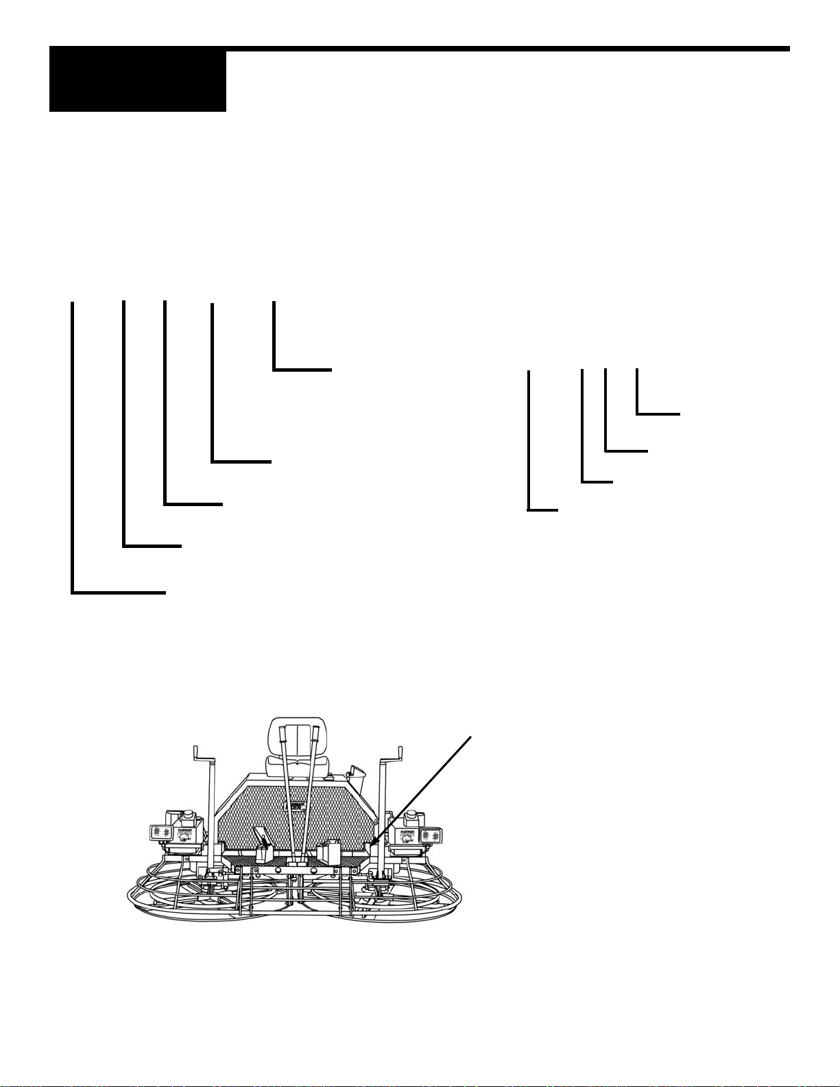
IDENTIFICATION PLATE
An identification plate listing the Model Number and Serial Number is attached to each unit and is located on the left side
of the mainframe. The plate should not be removed.
Please record the information found on this plate below so it will be available should the identification plate become lost or
damaged . When ordering parts or requesting service information you will always be asked to specify the model number
and serial number of the unit.
Serial Number
The serial number found on the identification
plate is a ten digit number. The model number
identifies your machine and will ensure that you
receive the correct replacement parts.
900 0899 001
Production
Sequence
Identification
Plate
Location
FILL IN FOR FUTURE REFERENCES
Model Number:___________________
Serial Number:___________________
Date Purchased:__________________
Purchased From:_________________
________________________________
1A-2
Model Number
PRO 900-NOL-SFC 20KA
ENGINE
20 HP KAWASAKI
20 HP LINAMAR
20 HP HONDA
25 HP KOHLER
GEAR BOX
STANDARD FAN COOLED
ROTOR SIZE
900 mm
NON-OVERLAPPING
BLADES
PRO SERIES
PRO 900
Year
Month
Series

1A
OPERATIONS
PRO 900-NOL-SFC Operating Information
TABLE OF CONTENTS
1.1 Safety Note . . . . . . . . . . . . . . . . . . . . . . . . . . . . . . . . . . . . . . . . . . .1A-6
1.2 Laws Pertaining to Spark Arrestors . . . . . . . . . . . . . . . . . . . . . . . . .1A-6
1.3 Operating Safety . . . . . . . . . . . . . . . . . . . . . . . . . . . . . . . . . . . . . . .1A-7
1.4 Service Safety . . . . . . . . . . . . . . . . . . . . . . . . . . . . . . . . . . . . . . . . .1A-8
1.5 Dimensions . . . . . . . . . . . . . . . . . . . . . . . . . . . . . . . . . . . . . . . . . . .1A-8
1.6 Technical Data . . . . . . . . . . . . . . . . . . . . . . . . . . . . . . . . . . . . . . . . .1A-9
1.7 Description . . . . . . . . . . . . . . . . . . . . . . . . . . . . . . . . . . . . . . . . . . . .1A-10
1.8 Before Starting . . . . . . . . . . . . . . . . . . . . . . . . . . . . . . . . . . . . . . . . .1A-10
1.9 Starting . . . . . . . . . . . . . . . . . . . . . . . . . . . . . . . . . . . . . . . . . . . . . .1A-10
1.10 Operating . . . . . . . . . . . . . . . . . . . . . . . . . . . . . . . . . . . . . . . . . . . . .1A-11
1.11 Stopping . . . . . . . . . . . . . . . . . . . . . . . . . . . . . . . . . . . . . . . . . . . . .1A-11
1.12 Steering . . . . . . . . . . . . . . . . . . . . . . . . . . . . . . . . . . . . . . . . . . . . . .1A-12
1.13 Pitch Adjustment . . . . . . . . . . . . . . . . . . . . . . . . . . . . . . . . . . . . . . .1A-12
1.14 Periodic Maintenance Schedule . . . . . . . . . . . . . . . . . . . . . . . . . . .1A-13
1.15 Trowel Gearbox . . . . . . . . . . . . . . . . . . . . . . . . . . . . . . . . . . . . . . . .1A-13
1.16 Drive Belts . . . . . . . . . . . . . . . . . . . . . . . . . . . . . . . . . . . . . . . . . . . .1A-14
1.17 Control Linkage Lubrication . . . . . . . . . . . . . . . . . . . . . . . . . . . . . .1A-14
1.18 Control Linkage Adjustment (Forward and Reverse) . . . . . . . . . . .1A-15
1.19 Right Hand Control Lever Adjustment (Right or Left) . . . . . . . . . . .1A-15
1.20 Lift Lever Adjustment . . . . . . . . . . . . . . . . . . . . . . . . . . . . . . . . . . . .1A-16
1.21 Transporting Trowels . . . . . . . . . . . . . . . . . . . . . . . . . . . . . . . . . . . .1A-17
1.22 Battery Jump Start Procedures . . . . . . . . . . . . . . . . . . . . . . . . . . . .1A-18
This machine is built with user safety in mind. However, it can present hazards if
improperly operated and serviced. Follow operating instructions carefully!
If you have any questions about operating or servicing this equipment please contact
your Allen Engineering Distributor or Allen Engineering Corp. Customer Service at
800-643-0095 or 870-236-7751.
1A-3

1A
OPERATIONS
Important Reminder
Complete any warranty requirements as specified by the engine manufacturer in their instructions found inside
the battery box.
Y our engine and clutch is not manufactured by Allen Engineering Corp., and therefore is not covered under Allen
Engineering warranty.
Your engine manufacturer should be contacted if you wish to purchase a parts manual or a repair manual for
your engine.
Refer to enclosed owners engine manual for complete O&M instructions. See your battery manufacturer for
battery warranty.
Your Distributor
Your Distributor has Allen Engineering trained mechanics and original Allen Engineering replacement parts.
Always contact the Allen Engineering Distributor who sold you this machine for Allen Engineering Certified
repairs and replacement parts.
Place distributor information here for future reference.
1A-4
DISTRIBUTOR NAME: PHONE NUMBER:
ADDRESS:
CITY:
STATE:
ZIP:
SALESMAN:
ADDITIONAL INFORMATION:

1A
OPERATIONS
THE INFORMATION CONTAINED IN THIS MANUAL WAS BASED UPON THE MACHINES
IN PRODUCTION AT THE TIME (BEGINNING WITH SERIAL NUMBER 9000402013) OF
PUBLICATION. ALLEN ENGINEERING RESERVES THE RIGHT TO CHANGE ANY PORTION OF THIS DOCUMENT WITHOUT NOTIFICATION.
Information Contained in This Manual
Ordering Parts
This manual contains an illustrated parts list for help in ordering replacement parts for your machine. Follow
the instructions listed below when ordering parts to ensure prompt and accurate delivery. All orders for parts
must be made through your local authorized Allen Engineering dealer. All authorized Allen Engineering dealers must fax a copy of the parts order to customer service. The fax number is (870) 236-3934. Facsimile orders
must contain the following information:
1. On all orders for service parts include SERIAL NUMBER and MODEL number.
2. Shipment may be delayed if this information is not included.
3. Include correct description and part number from part section 2A.
4. State exact shipping instructions including preferred routing and complete destination
address. Also please indicate your preferred freight carrier. If no freight carrier is
indicated Allen Engineering reserves the right to ship the shipment the best way
possible. Once a shipment leaves Allen Engineering’s docks it becomes the
responsibility of the freight carrier to insure that it arrives at it’s intended
destination.
5. DO NOT return parts to Allen Engineering without receiving written authorized Returned
Goods Authorization (RGA) from Allen Engineering. All authorized returns must bee shipped
prepaid. All unauthorized returns will be shipped back to the addressee at their
expense.
Keep this manual or a copy of it with the machine. If you loose this manual or need an additional copy
please contact your Allen distributor or Allen Engineering Corporation at (800) 643-0095 and order literature part number 038958.
© 2002 Allen Engineering Corp.
All Rights Reserved -- Contents Subject to
Change Without Prior Notice.
This manual provides information and procedures to safely operate and maintain the Allen Engineering PRO
900-NOL-SFC Model Razorback
®
Riding Trowels.
For your own safety and protection from personal injury carefully read, understand and observe the safety
instructions described in this manual.
Always operate and maintain this machine in accordance with the instructions described in this manual. A well
maintained piece of equipment will provide many years of trouble free operation. This manual is divided into the
sections listed below.
1A-5
1A
OPERATIONS
2A
PARTS

1A
OPERATIONS
1.1 Safety Notes
This manual contains NOTES, CAUTIONS and WARNINGS which must be followed to reduce the possibility of
improper service damage to the equipment or personal injury. Read and follow all NOTES, CAUTIONS and
WARNINGS included in this manual.
NOTE Contains additional information important to a procedure.
CAUTION Provides information important to prevent errors which could damage machine or components.
WARNING Warns of conditions or practices which could lead to personal injury or death.
1.2 Laws Pertaining to Spark Arrestors
Notice: Some states require that in certain locations arrestors be used on internal combustion engines. Aspark
arrester is a device designed to prevent the discharge of spark or flames from the engine exhaust. It
is often required when operating equipment on forested land to prevent the risk of fires. Consult the
engine distributor or local authorities and make sure that you comply with regulations regarding spark
arrestors.
1A-6

1A
OPERATIONS
1.3 Operating Safety
Familiarity and proper training are required for the safe operation of this equipment! Equipment operated
improperly or by untrained personnel can be dangerous! Read the operating instructions contained in both this
manual and the engine manual and familiarize yourself with the location and proper use of all controls.
Safety Precautions
1. Read operating and safety instructions before using the Riding Trowel. Operate the machine in
accordance with the manufacturer's instructions.
2. Inspect your Riding Trowel for damage or tampering that can sometimes occur
during shipping.
3. If damage is found file a claim with your carrier immediately! Mark freight bill of
lading as damaged shipment.
4. Do not operate Riding Trowel if any guards have been removed or if the "safety
switch" is not operational.
5. Only trained personnel should be allowed to operate your Riding Trowel.
6. Never allow more than one person on the Riding Trowel while it is in operation.
7. No foreign objects such as buckets, tools or materials should ever be attached or
allowed to ride on the Trowel during operation.
8. Do not attempt to fill fuel tank or oil sump while the engine is running. Allow engine to
cool before refueling.
9. Never attempt to operate the Riding Trowel on steep inclined surfaces.
10. Do not use over the counter hardware to replace manufacturer's hardware.
11. WARNING: When operating machines with gas engines in confined areas. The
fumes MUST
be ventilated!
12. Always wear safety goggles, ear protection, and gloves when operating the Riding
Trowel.
13. When operating Pro 900 Edger, never put hands on or near the edger rings. There are several
pinch point
decals loacted on the rings. Please adhere to the warnings to prevent serious injury.
1A-7

1A
OPERATIONS
1.4 Service Safety
Poorly maintained equipment can become a safety hazard! In order for the equipment to operate safely and
properly over a long period of time, periodic maintenance and occasional repairs are necessary.
DO NOT attempt to clean or service machine while it is running. Rotating parts can cause severe injury.
DO NOT crank a flooded engine with the spark plug removed. Fuel trapped in the cylinder will squirt out the
spark plug opening.
DO NOT test for spark if engine is flooded or the smell of gasoline is present . A stray spark could ignite the
fumes.
DO NOT use gasoline or other types of fuels or flammable solvents to clean parts especially in
enclosed areas. Fumes from fuels and solvents can become explosive and can be hazardous to
your health.
ALWAYS operate machine with all safety devices and guards in place and in working order.
ALWAYS keep area around muffler free of debris such as leaves, paper, cartons, etc. A hot muffler could
ignite such items starting a fire.
ALWAYS replace worn or damaged components with spare parts designed and recommended by ALLEN
ENGINEERING.
ALWAYS disconnect battery on machines before servicing to avoid accidental start-up.
1.5 Dimensions
OPERATOR’S
RIGHT HAND
OPERATOR’S
LEFT HAND
41”
1041 mm
84”
2133 mm
52”
1320 mm
1A-8

1A
OPERATIONS
1A-9
1.6 Technical Data
Engine Make & Model Kaw. 22HP Koh. 25HP Hon. 20HP Lin. 20HP
Rated Power HP (kW) 22(16.4) 25(18.6) 20(14.9) 20(14.9)
Piston Displacement cu. in. (cc) 38 (624) 44(725) 37.5(614) 47.7(782)
Spark Plug type Champion RC12YC Champion RC12YC BPR6ES NGK Champion RC12YC
Electrode Gap in. (mm) .025 (64) .040(1.02) .025(64) .025(64)
Operating Speed RPM 3600 3600 3600 3600
Battery volts 12 12 12 12
Fuel Capacity gal. (L) 4(15.14) 4(15.14) 4(15.14) 4(15.14)
Fuel Consumption gal. (L) per hr 1.66 (6.27) 1.66(6.27) 1.66(6.27) 1.66(6.27)
Running Time hrs 2.5 2.5 2.5 2.5
Centrifugal Clutch type Mechanical Ramp Mechanical Ramp Mechanical Ramp Mechanical Ramp
Low Oil Shutdown Alert Yes No Yes Yes
Engine Oil Capacity US qt. (L) 2 (1.9) 2(1.9) 1.3(1.2) 2.7(2.6)
Engine Lubrication Oil Grade SAE10W30 SG SAE10W30 SG SAE10W30 SG SAE10W30 SG
Weight lbs. (kg) 91 (41) 94(43) 90(40) 94(43)
Charging System amp 20 20 20 35
Trowel Specifications Pro 900-NOL-SFC Pro 900-NOL-SFC-EDGER
Length in. (mm) 84 (2133) 88 (2235)
Width in. (mm) 41 (1041) 40 (1016)
Operating Weight lbs. (kg) 700 (318) 786 (357)
Detachable Guard Rings Yes No
Troweling Width in. (mm) 70 (1778) 85 (216)
Troweling Area sq. ft. m
2
17.5 (1.63) 17.5 (1.63)
Travel Speed ft/min. (mm/min.) 230 (70) 230 (70)
Rotor Speed RPM 115 125
Pitch Range deg. 0 -20 0-20
Gearbox Standard Fan Cooled (SFC) Standard Fan Cooled (SFC)
Safety Switch Foot Style Yes Yes
Gearbox Lubrication 25 oz. Mobile Mobilith SCH 220 Mobil Mobilith SCH 220
Summary Data for CE Marking Sound & Vibration Testing
Test Machine Engine Avg. Sound Operator Calculated Seat Foot Hand
Type Pressure Ear SPL Sound Power Vibration Vibration Vibration
Level (SPL) Level Overall Overall Maximum
dB(A) dB(A) dB(A) m/sec
2
m/sec
2
m/sec
2
900 OL STD Onan 20 95 95 110 1.3 0.6 1.3
900 NOL STD Onan 20 95 93 111 0.4 0.4 1.3
This information was acquired from extensive sound and vibration analysis tests ran at Allen Engineering
Corporation. The data above was acquired from May till June of 1996.
1A
OPERATIONS
1.7 Description
The Riding Trowel is a modern high production machine. Finishing rate will vary depending on the operators
skill and job conditions. The Riding Trowel has eight finishing blades. The St andard Fan Cooled Gearboxes are
designed to provide exceptional performance with low maintenance and trouble free use under some of the
most worse conditions. All Allen Engineering Razorback
®
Riders are equipped with a safety shutdown switch
and a low oil shut down for added job safety and engine protection. Operating time between fuel refills is approximately 2-1/2 to 3 hours with a rotor speed up to 155 RPM for a PRO 900-NOL-SFC (depending on model). The
Razorback
®
Riders are the most technically advanced trowels on the market today. With Proper maintenance
and use your Riding Trowel will provide you with exceptional service.
1.8 Before Starting
Before starting trowel check the following:
* Oil level in engine:
* Oil level in trowel gearboxes:
* Fuel level :
* Condition of air filter:
* Condition of trowel arms and blades:
* Grease trowel daily:
1.9 Starting
Before starting trowel refer to drawing above for location and identification of controls.
1. Sit down correctly on the Riding Trowel Seat. DO NOT attempt to start the Riding Trowel with out
an operator in the seat.
2. Place left foot on the safety switch pedal located on the operators left hand side. Press down
gently engaging the safety switch and maintain slight pressure.
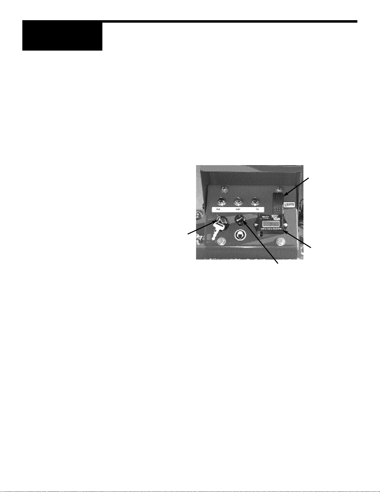
3. If engine is cold pull out the choke lever located on the control panel (refer to drawings
above).
4. Press down on throttle pedal (located by the operator's right foot) one to two times. NOTE:
To much throttle during start-up will flood the engine.
5. Turn key to the start-position. immediately release key when engine starts. If after two or
three attempts the engine has not started push in choke. This will open the choke. Attempt to
start trowel again. Allow engine to warm up before operating trowel.
Caution: Operating the starter for more than 5 seconds can damage the starter or engine. If engine fails to
start release the switch and wait 10 seconds before operating starter again.
LIGHT SWITCH
HOURMETER
CHOKE KNOB
KEY SWITCH
1A-10
1A
OPERATIONS
1.10 Operating
To utilize your Allen Engineering Razorback®Rider to its fullest capacity the machine should be driven in the
direction the operator is facing. This will finish the widest possible area while giving the operator an excellent
view of the slab surface about to be troweled. When the machine reaches the end of the slab make a 180
degree turn and repeat the straight line of direction to the other end of the slab. To familiarize a new operator
with the Riding Trowel the following steps should be taken.
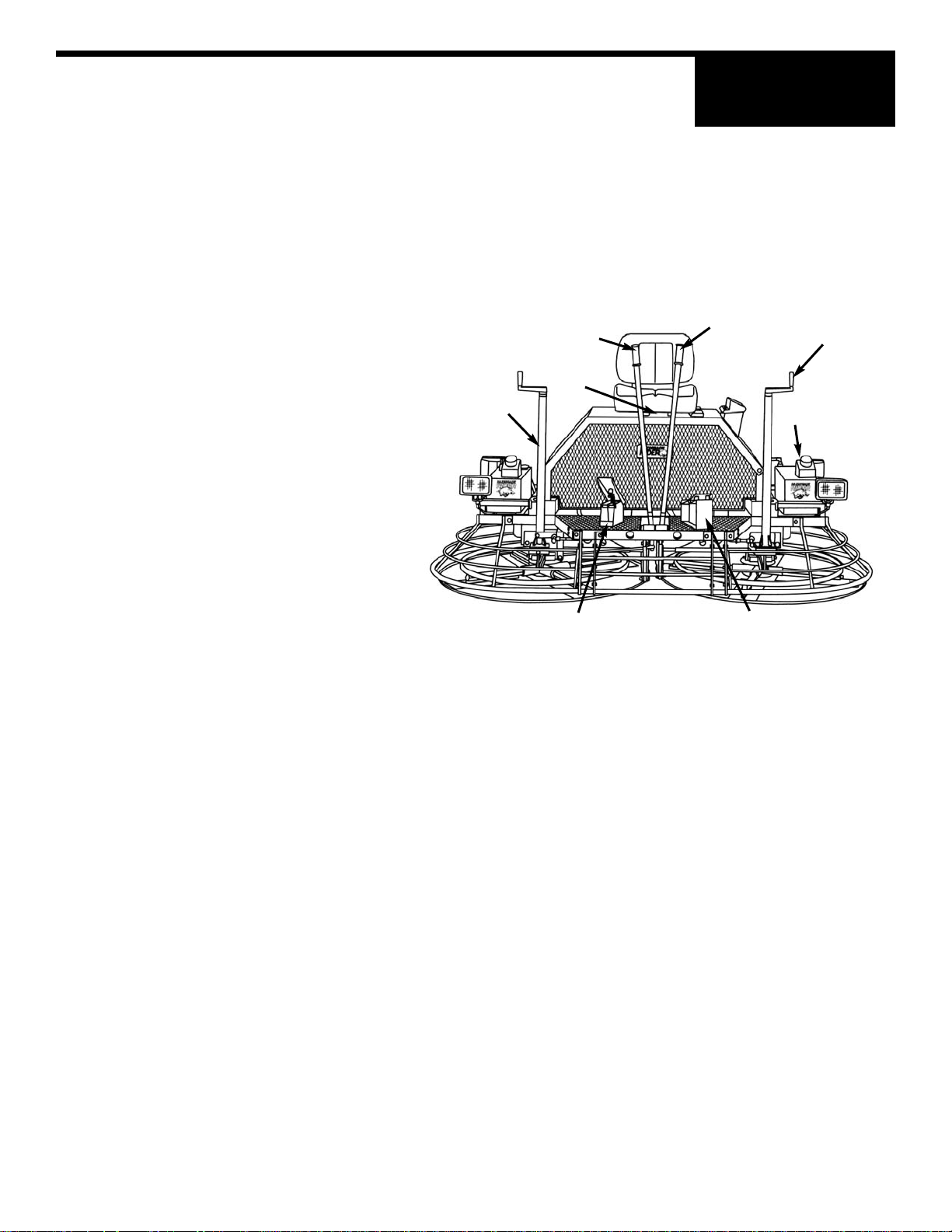
1. Point out the location of all Controls
A. right pitch control
B. control lever (forward reverse)
C. control lever (left & right, forward &
reverse
D. left pitch control
E. right foot pedal (throttle control)
F. left foot pedal (safety switch)
G. seat adjustment
H. fuel gauge
A
B
C D
E
F
G
H
2. With the operator in the seat, show him the functions of the control levers (B) and (C) and how to start the
machine. (refer to page 1A-10)
A hard level concrete slab with water on the surface is an idea place for an operator to practice with the
machine. For practice pitch the blades up approximately 1/4" on the leading edge. St art by making the machine
hover in one spot and then practice driving the machine in a straight line and making 180 degree turns. Best
control is achieved at full RPM.
CAUTION: After starting engine fully engage the throttle. This allows the engine to warm up quicker and also
engages the centrifugal clutch to max. RPM'S. NOTE: If you start out at a low RPM this will partially engage
the clutch, causing it to slip. This will severely damage the clutch, causing clutch failure.
CAUTION: DO NOT use excessive pressure on the control levers. Excessive pressure does not increase the
reaction time of the machine and can damage steering controls.
1.11 Stopping
To stop the trowels movement, return the control levers (C) and (B) to their neutral position and release pressure on the right foot pedal (E) .
NOTE: On units equipped with an optional cruise control push lever all the way down this will release the right
foot pedal and reduce engine speed to disengage the clutch. To stop engine turn the key to the off position.
1A-11
1A
OPERATIONS
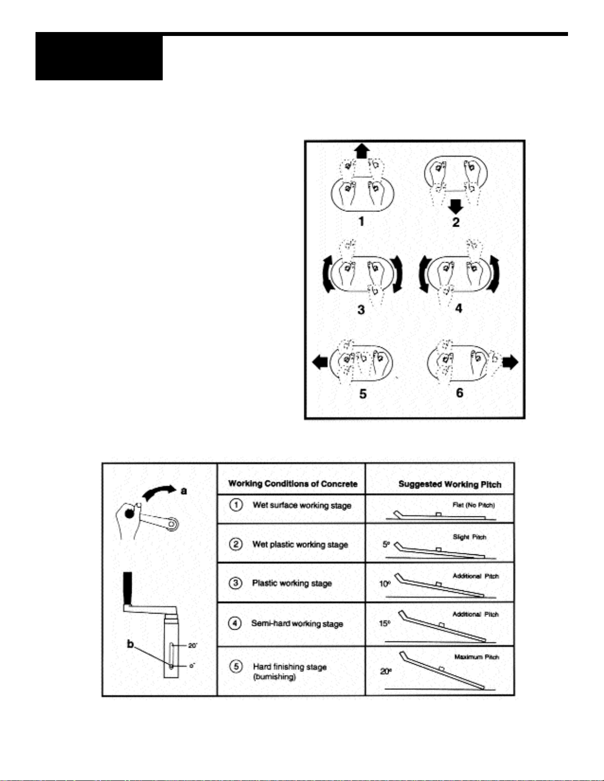
1.12 Steering
A slight "feathering motion" forward and backward with the left hand control lever is required to move the
machine in a straight path to the left or right while operating the right hand control lever. See illustration.
1 forward
2 reverse
3 rotate clockwise
4 rotate counter clockwise
5 left sideways
6 right sideways
1.13 Pitch Adjustment
Different pitch angles are needed as you work the different stages of the concrete. See the drawing below.
When changing or setting pitch (angle of trowel
blades), slow the machine down, set the desired
degree of pitch on the left side of the machine and
then adjust the right side to match.
To increase the pitch, turn the pitch control clockwise
(a) use the pitch indicator (b) to adjust pitch equally on
both right and left trowel blades.
1A-12

1A
OPERATIONS
1.14 Periodic Maintenance Schedule
The chart below list basic trowel and engine maintenance. Refer to engine manufacturer's Operation Manual
for additional information on engine maintenance. A copy of the engine Operator's Manual was supplied with
the machine when it was shipped. To Service the engine pull the seat locking pin out and tilt seat back.
DAILY EVERY 20 EVERY 50 EVERY 100 EVERY 300
HOURS HOURS HOURS HOURS
GREASE TROWELARMS X
CHECK OIL LEVEL IN G-BOX X
CHECK FUEL LEVEL X
INSPECT AIR FILTERS X
REPLACE AS NEEDED
CHECK AND TIGHTEN X
EXTERNAL HARDWARE
GREASE CONTROL LINKAGE X
CHECK DRIVE BELTS X
CHECK VALVE CLEARANCE X
CHANGE ENGINE OIL X
REPLACE OIL FILTERS X
OIL CROSSHEAD X
GREASE TROWEL G-BOX X
REPLACE SPARK PLUG X
1.15 Trowel Gearbox
1. Check Oil levels in the gearbox daily (every 8 hours) Add oil if oil level is below the check sight glass. To add
oil tilt trowel back and remove the side plug. Add Oil through hole opening. Replace plug af ter proper level has
been achieved. DO NOT Fill past the plug. Use only Mobil Oil SHC 634, synthetic ISO VG 460.
2. Each Gearbox has a grease fitting on top cover that must be greased (2 SHOTS ONLY) every 300 operat-
ing hours. Use only Mobilith SHC 220. Extended pressure grease.
1A-13

1A
OPERATIONS
1.16 Drive Belts
To Tighten Belts
1. Loosen the four engine bolts.
2. Then locate the engine plate adjustment screws, on
the back of the engine.
3. Next loosen the nylon locknuts and jamnuts.
4. Turn all nylon locknuts counterclockwise an equal
number of turns to pull the engine backward until correct belt tension is attained. Maximum belt play
should be from 1/2” to 3/4” (13mm to 19mm) at the
center of the span. New belts sould be re-tensioned
after the first 10 to 12 hours of operation.
5. Retighten all jam nuts and locknuts.
To Replace Belts
1. Remove Belt Guard.
2. Loosen the four engine mounting bolts.
3. Locate the two engine plate adjustment screws.
These screws are located in the rear of the engine.
4. Loosen al the jamnuts and nylon locknuts on the
engine plate adjustment screws.
5. Tighten the two jamnuts clockwise, this will push the
engine forward and relieve the belt tension.
6. Loosen set screws (a) and (b) on the flex coupler
assembly (c).
7. Remove six attaching bolts (d) on the inside of the
flex coupler assembly (e) and slide the flex coupler
mount (c) toward gearbox so as to allow the inside
spider assembly (e) to be removed intact.
8. Remove and install belts through opening created
by removal of (e).
9. Reverse procedure for assembly. Do not over tight
en the bolts on the flex coupler assemblies. Tighten
screws (n) so that washers (m) are compressed
halfway into discs.
NOTE:
Remember that new belts should be re-tensioned after the first 10 to 12 hours of use. Maximum
belt play should be from 1/2” to 3/4” (13mm to 19mm)
at the center of the span.
1A-14
1A
OPERATIONS
1.17 Control Linkage Lubrication
The control linkage is equipped with seven grease fitting to lubricate pivot points. Grease control linkage once
a week or every 20 hours to prevent wear and ensure free movement and smooth response of control levers.
Use a general purpose grease and add one to two shots of grease to each fitting.
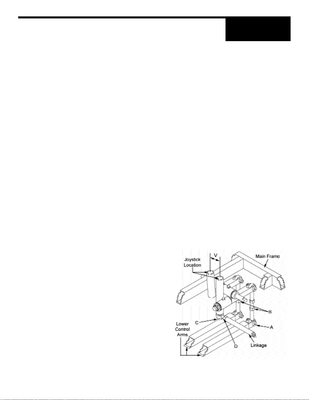
1.18 Control Lever Adjustment
Be sure that the trowel is on a level surface. The control levers should line up evenly. If levers appear out of
adjustment they can be re-adjusted forward or backwards as follows:
NOTE: Trowel must be placed on flat level surface that fully supports the blades on both rotors.
1. Remove bolts (A).
2. Loosen jam nuts (B).
3. Extend linkage to adjust control levers backward.
4. Shorten linkage to adjust linkage control levers forward.
5. After levers have been adjusted to the desired position,reassemble bolts (A) and tighten jam
nuts (B).
1.19 Right Hand Control Lever
Adjustment Right or Left
The right hand lever should be set to the same angle
as that of the left to form a "V". If levers become out of
adjustment adjust the right hand lever as follows:
1. Remove bolt (C).
2. Loosen jam nuts (D).
3. Extend linkage to move control levers to the right .
4. Shorten linkage to move control levers to the left.
5. After control lever has been adjusted to the desired
position reassemble bolt (C). And tighten jam
nuts (D).
1A-15
 Loading...