

Allegro UDN2998W Datasheet
2998
DUAL FULL-BRIDGE
MOTOR DRIVER
As an interface between low-level logic and solenoids, dc (brush)
motors, or stepper motors, the UDN2998W dual full-bridge driver will
operate inductive loads up to 50 V with continuous output currents of
up to 2 A per bridge or peak (start-up) currents to 3 A. The control
inputs are compatible with TTL, DTL, and 5 V CMOS logic. Except
for a common supply voltage and thermal shutdown, the two drivers in
each package are completely independent.
For external PWM control, an Output Enable for each bridge
circuit is provided and the sink driver emitters are pinned out for
connection to external current-sensing resistors. The chopper drive
mode is characterized by low power dissipation levels and maximum
efficiency. A PHASE input to each bridge determines load-current
direction.
Data Sheet
29319.6B†
Dwg. No. W-106
ABSOLUTE MAXIMUM RATINGS
at T
≤ +150°C
J
Supply Voltage, VBB.......................... 50 V
Output Current, I
(peak) ........................................... ±3 A
Sink Driver Emitter Voltage, VE...... 1.5 V
Logic Input Voltage Range,
V
or V
PHASE
Package Power Dissipation,
PD....................................... See Graph
Operating Temperature Range,
TA.............................. -20°C to +85°C
Storage Temperature Range,
TS............................. -55°C to +150°C
NOTE: Output current rating may be limited
by chopping frequency, ambient temperature, air flow, or heat sinking. Under any set
of conditions, do not exceed the specified
current rating or a junction temperature of
+150°C.
(continuous) ..... ±2 A
OUT
....... -0.3 V to 15 V
ENABLE
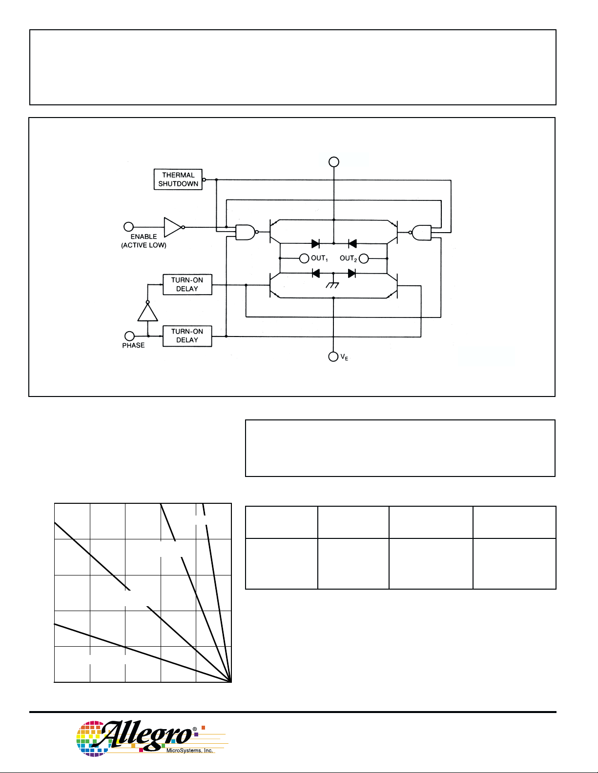
Extensive circuit protection is provided on-chip. Both groundclamp and flyback diodes for each bridge are provided. A thermal
shutdown circuit disables the load drive if chip temperature rating
(package power dissipation) is exceeded. Internally-generated delays
provide crossover-current protection.
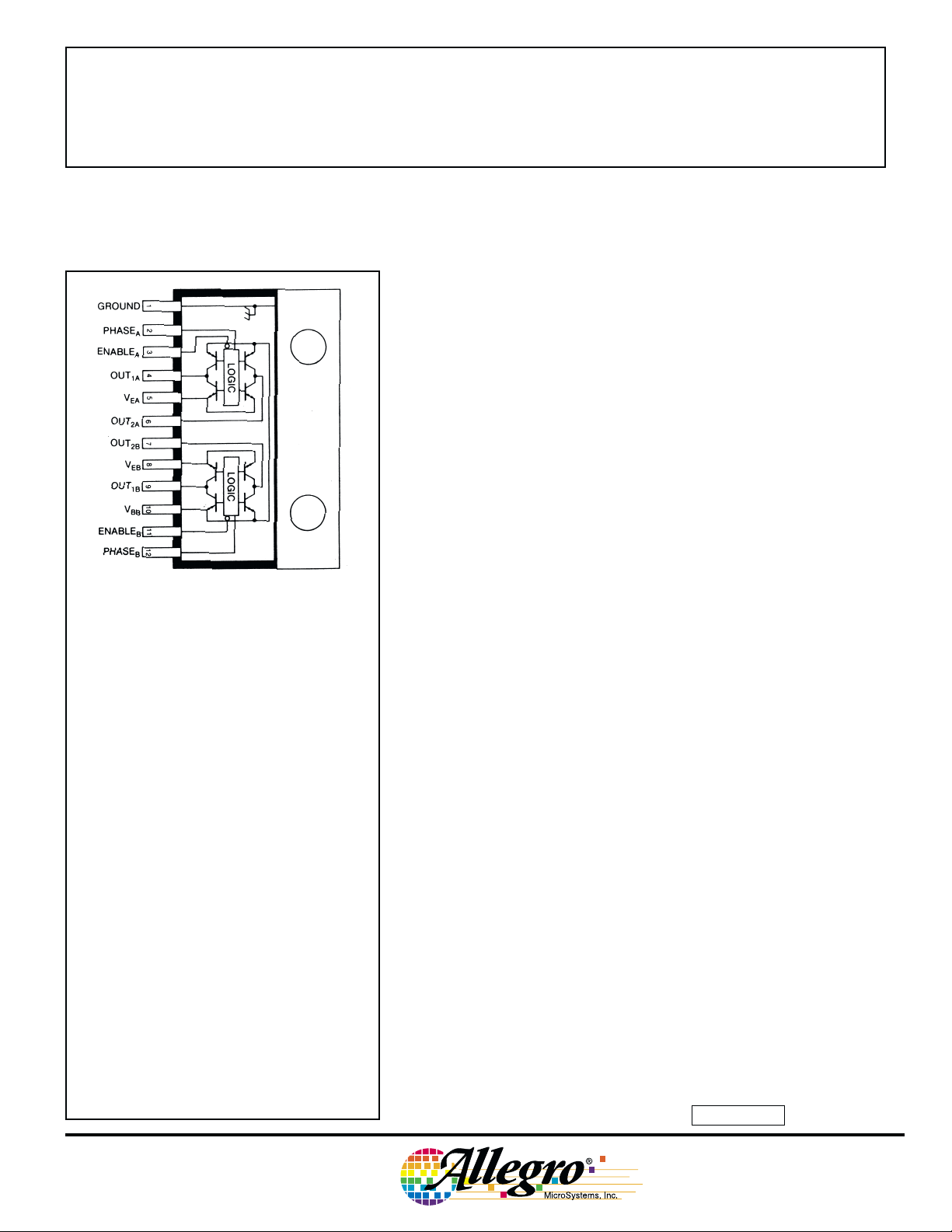
The UDN2998W is packaged in a 12-pin single in-line power-tab
package for high power capabilities. Driving either of the bridges at
the full 2 A dc rating requires the use of an external heat sink. The tab
is at ground potential and needs no insulation.
FEATURES
■ ±3 A Peak Output Current
■ Output Voltage to 50 V
■ Integral Output Suppression Diodes
■ Output Current Sensing
■ TTL/CMOS Compatible Inputs
■ Internal Thermal Shutdown Circuitry
■ Crossover-Current Protected
■ Automotive Capable
Always order by complete part number: UDN2998W .
2998
DUAL FULL-BRIDGE
MOTOR DRIVER
FUNCTIONAL BLOCK DIAGRAM
(ONE OF TWO DRIVERS)
BB
Dwg. No. W-107A
To maintain isolation between integrated circuit components and to
provide for normal transistor operation, the ground tab must be
connected to the most negative point in the external circuit.
10
R = 2.0°C/W
θJT
8
6
12°C/W HEAT SINK
4
2
FREE AIR, R = 38°C/W
3.0°C/W HEAT SINK
R = 14°C/W
θJA
θJA
R = 5.0°C/W
θJA
ENABLE PHASE
INPUT INPUT OUTPUT 1 OUTPUT 2
Low High High Low
Low Low Low High
High High Open Low
High Low Low Open
TRUTH TABLE
0
ALLOWABLE PACKAGE POWER DISSIPATION IN WATTS
25
50 75 100 125 150
TEMPERATURE IN °C
Dwg. GP-012B
115 Northeast Cutoff, Box 15036
Worcester, Massachusetts 01615-0036 (508) 853-5000
Copyright © 1985, 2000 Allegro MicroSystems, Inc.
 Loading...