

TFA8x Series
Reverse Blocking T riode Thyristor
Features and Benefits
▪ Exceptional reliability
▪ Small fully-molded SIP package with heatsink mounting
for high thermal dissipation and long life
▪ Operating junction temperature to 150°C
▪ V
of 700 or 800 V
DRM
▪ 8.0 A
▪ 7 mA typical gate trigger current
▪ Uniform switching
▪ UL Recognized Component (File No.: E118037) (suffix I)
on-state current
RMS
Package: 3-pin SIP (TO-220F)
Description
This Sanken reverse blocking triode thyristor is designed for
AC power control, providing reliable, uniform switching for
half-cycle AC applications.
In comparison with other products on the market, the TFA8x
series provides increased isolation voltage (1800 VAC
guaranteed for up to 1 minute. In addition, commutation
dv/dt is improved.
RMS
),
Applications
▪ Motor control for small tools
▪ Temperature control, light dimmers, electric blankets
▪ General use switching mode power supplies (SMPS)
Not to scale
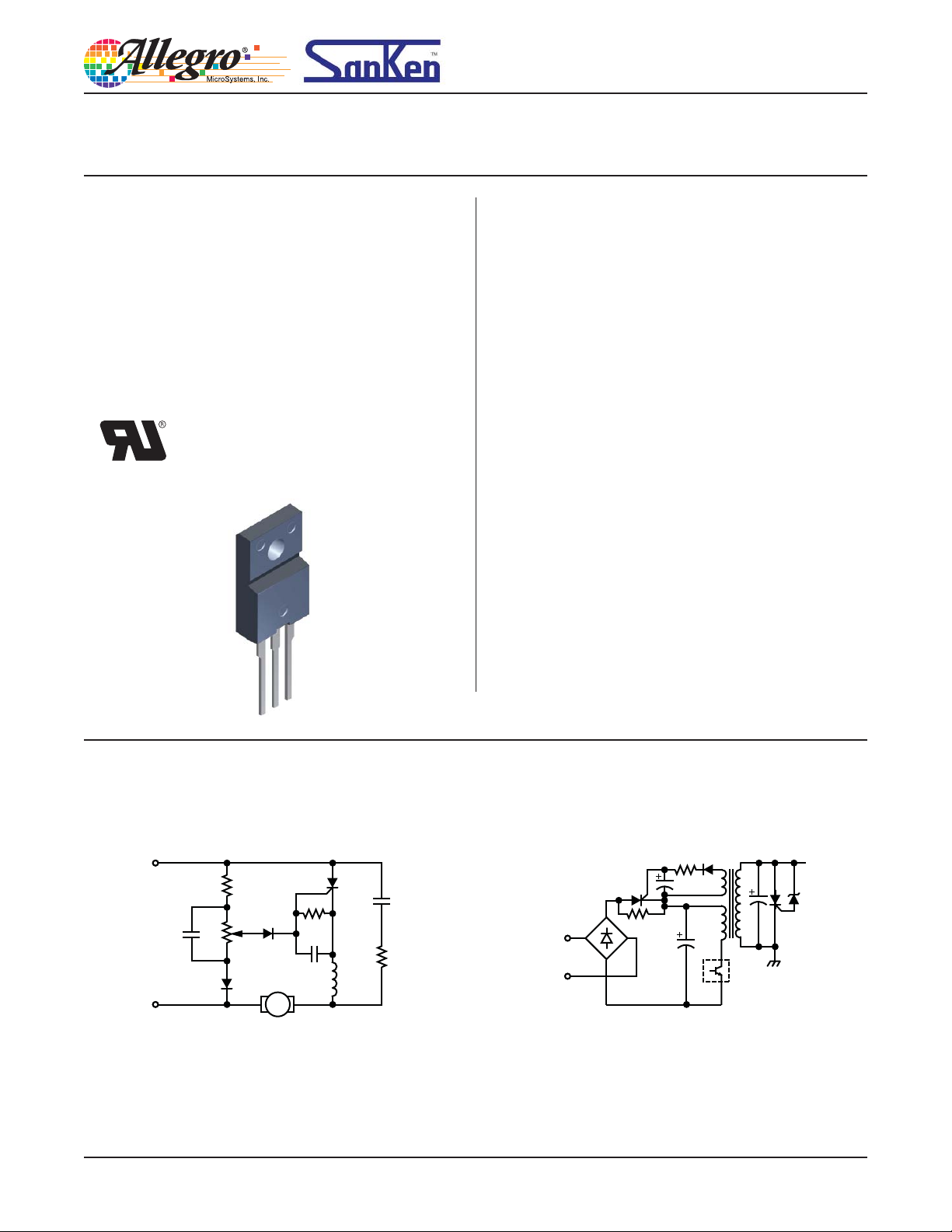
Typical Applications
M
Single-phase motor control (for example, electric tool) In-rush current control (for example, SMPS)
28105.03, Rev. 1
TFA8x
Reverse Blocking T riode Thyristor
Series
Selection Guide
V
Part Number
TFA87(I) 700 Yes
TFA87S 700 –
TFA88(I) 800 Yes
TFA88S 800 –
DRM
(V)
Absolute Maximum Ratings
Characteristic Symbol Notes Rating Units
Peak Repetitive Off-State Voltage V
Isolation Voltage V
Average On-State Current I
RMS On-State Current I
Surge On-State Current I
I2t Value for Fusing I2t Value for 50 Hz half cycle sine wave, 1 cycle, I
Critical Rising Rate of On-State Current di/dt
Peak Forward Gate Current I
Peak Forward Gate Voltage V
Peak Reverse Gate Current V
Peak Gate Power Dissipation P
Average Gate Power Dissipation P
Junction Temperature T
Storage Temperature T
DRM
T(AV)
T(RMS)
TSM
FGM
FGM
RGM
GM(AV)
UL-Recognized
ISO
GM
J
stg
Component
TFA87x
TJ = –40°C to 150°C, R
TFA88x
AC RMS applied for 1 minute between lead and case 1800 V
50 Hz half cycle sine wave, Conduction angle (α) = 180°,
continuous operation, TC = 98°C
f = 60 Hz
f = 50 Hz 120 A
I
= I
T
T(RMS)
ns, igp 30 mA (refer to Gate Trigger Circuit diagram)
f 50 Hz, duty cycle 10% 2.0 A
f 50 Hz, duty cycle 10% 10 V
f 50 Hz 5.0 V
f 50 Hz, duty cycle 10% 5.0 W
TJ < TJ(max) 0.5 W
Half cycle sine wave, single, non-repetitive
× π, VD = V
× 0.5, f ≤ 60 Hz, tgw 10 s, tgr ≤ 250
DRM
Package Packing
3-pin fully molded SIP with
heatsink mount
GREF
50 pieces per tube
= 1 k
= 120 A 72 A2 • s
TSM
700 V
800 V
12.6 A
132 A
–40 to 150 ºC
–40 to 150 ºC
8.0 A
50 A/s
Thermal Characteristics May require derating at maximum conditions
Characteristic Symbol Test Conditions Value Units
Package Thermal Resistance
(Junction to Case)
R
θJC
For AC 3.5 ºC/W
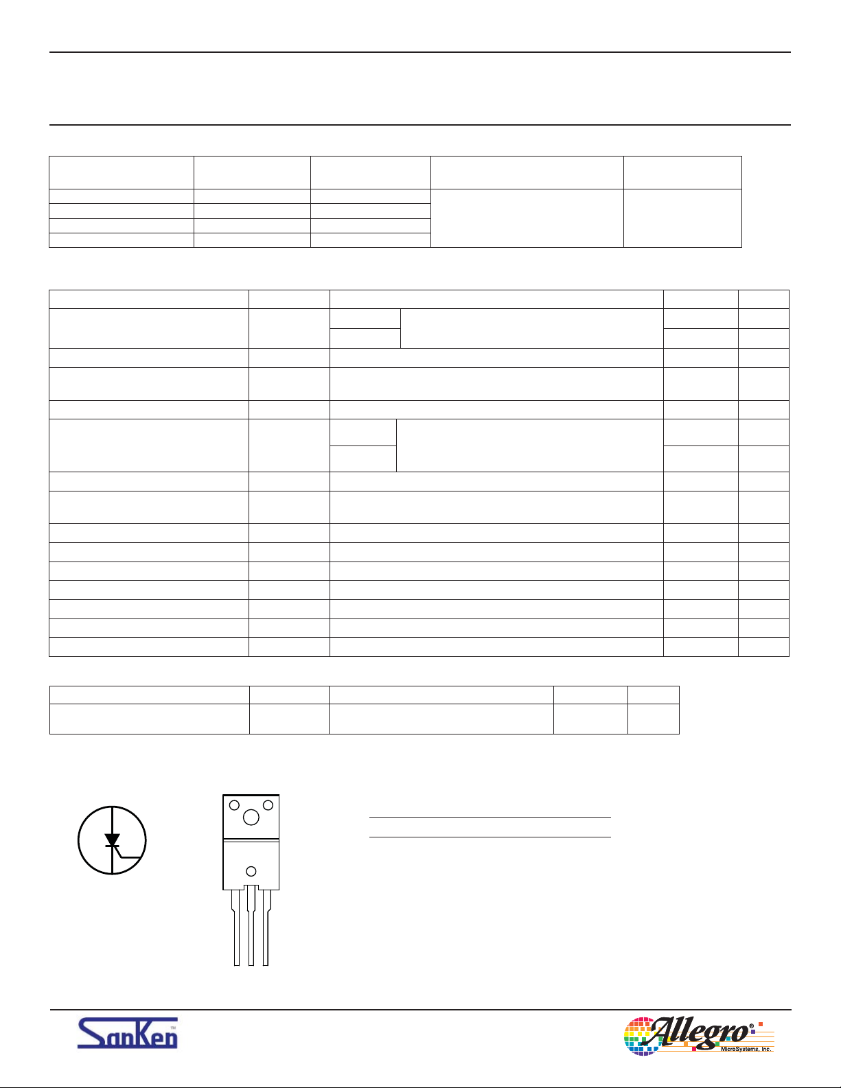
Pin-out Diagram
A
Number Name Function
G
K
123
Allegro MicroSystems, Inc.
115 Northeast Cutoff
Worcester, Massachusetts 01615-0036 U.S.A.
1.508.853.5000; www.allegromicro.com
Terminal List Table
1K
2 A Anode terminal
3 G Gate control
All performance characteristics given are typical values for circuit or
system baseline design only and are at the nominal operating voltage and
an ambient temperature, T
Cathode terminal
, of 25°C, unless oth er wise stated.
A
2
TFA8x
Reverse Blocking T riode Thyristor
Series
ELECTRICAL CHARACTERISTICS
Characteristics Symbol Test Conditions Min. Typ. Max. Unit
Off-State Leakage Current I
Reverse Leakage Current I
On-State Voltage V
Gate Trigger Voltage V
Gate Trigger Current I
Gate Non-trigger Voltage V
Holding Current I
Critical Rising Rate of
Off-State Voltage
DRM
RRM
dv/dt
VD = V
VD = V
I
TM
TM
VD = 6 V, RL = 10 , TC = 25°C – – 1.0 V
GT
VD = 6 V, RL = 10 , TC = 25°C – 7 15 mA
GT
VD = V
GD
R
H
GREF
VD = V
C
GREF
, TJ = 150°C, R
DRM
, TJ = 150°C, R
DRM
= 20 A, TC = 25°C – – 1.4 V
× 0.5, R
DRM
= 1 k, TJ = 25°C – 20 – mA
DRM
= 0.033 F
GREF
× 0.5, TJ = 125°C, R
= 1 k – – 2.0 mA
GREF
= 1 k – – 2.0 mA
GREF
= 1 k, TJ = 125°C 0.2 – – V
= 1 k,
GREF
– 300 – V/s
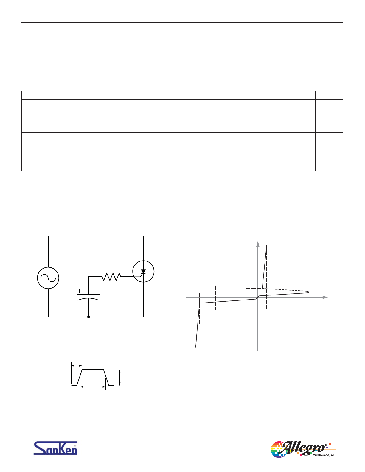
Test Circuit 1 Voltage-Current Characteristic
I
F
I
TM
R
GREF
C
GREF
Gate Trigger Current
t
gr
i
gp
t
gw
A
G
K
V
R
I
RRM
V
RRM
I
H
I
R
V
TM
(On state)
(Off state)
V
TM
V
DRM
I
DRM
V
F
Allegro MicroSystems, Inc.
115 Northeast Cutoff
Worcester, Massachusetts 01615-0036 U.S.A.
1.508.853.5000; www.allegromicro.com
3
TFA8x
Series
Reverse Blocking T riode Thyristor
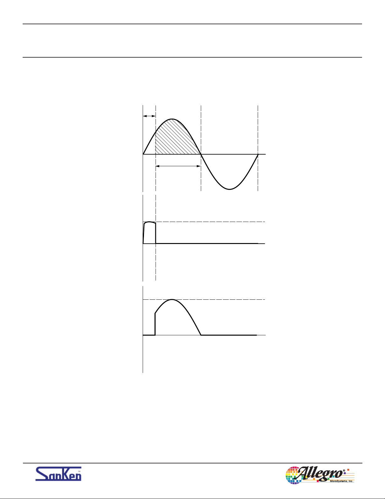
Commutation Timing Diagrams
Q
4
Supply VAC
V
GATE
On-State
Currrent
A
V
GT
I
TSM
Q
A = Conduction angle
Q
Q
Allegro MicroSystems, Inc.
115 Northeast Cutoff
Worcester, Massachusetts 01615-0036 U.S.A.
1.508.853.5000; www.allegromicro.com
4

TFA8x
Series
Reverse Blocking T riode Thyristor
Maximum On-State
Current versus
Maximum On-State
Voltage
Maximum Average
Power Dissipation
versus Average
On-State Current
100
10
(max) (A)
T
I
1
Performance Characteristics at TA = 25°C
= 150°C
T
J
Surge On-State
Current versus
Quantity of
T
= 25°C
J
Cycles
160
140
120
Half cycle sine wave
= 125°C
initial T
J
A= 10 ms, f = 20 ms
100
(A)
80
TSM
I
60
40
20
0
0.6 1.0 1.4 1.8 2.2 2.6 3.0 3.4
16
14
Half cycle sine wave
V
(max) (V)
T
12
10
(W)
T(AV)
P
A = 180°
A = 120°
8
6
A = 90°
A = 60°
A = 30°
Maximum Allowable
Case Temperature
versus Average
On-State Current
4
2
0
024681012 024681012
I
T(AV)
(A)
100
0
1 10 100
Quantity of Cycles
200
180
Half cycle sine wave
160
140
120
(°C)
C
100
T
80
A = 30°
60
A = 60°
40
A = 90°
20
A = 120°
A = 180°
0
I
T(AV)
(A)
2
Gate Voltage
versus
Gate Current
Typical Gate
Trigger Current
versus
Junction Temperature
= 6 V
at V
D
and R
= 10 Ω
L
= 2 A
I
= 0.2 V
V
GD
IG (mA)
GM
P
=
G(AV)
0.5 W
= 10 V
V
GM
10
(V)
G
V
0.1
(–40°C)
V
GT
= 1.5 V
(25°C)
V
1
GT
= 1 V
(–40°C)
I
GT
= 30 mA
(25°C) = 15 mA
I
GT
10 100 1000 10 000
100
10
(mA)
GT
I
1
0.1
–60 –20 20 60 100 140
TJ (°C)
P
GM
5 W
=
Allegro MicroSystems, Inc.
115 Northeast Cutoff
Worcester, Massachusetts 01615-0036 U.S.A.
1.508.853.5000; www.allegromicro.com
Typical Gate
Trigger Voltage
versus
Junction Temperature
= 6 V
at V
D
and R
= 10 Ω
L
= 10 kΩ
R
GREF
Typical
Holding Current
versus
Junction Temperature
= 10 kΩ
at R
GREF
V)
(
1
GT
V
0
–60 –20 20 60 100 140
TJ (°C)
100
10
(mA)
H
I
1
0.1
–60 –20 20 60 100 140
TJ (°C)
5

TFA8x
Series
Reverse Blocking T riode Thyristor
Transient Thermal Impedence versus Voltage Pulse Duration
10
1
(°C/W)
JC
Q
Z
0.1
1 10 100 1000 10 000 100 000
For AC
QT (ms)
Allegro MicroSystems, Inc.
115 Northeast Cutoff
Worcester, Massachusetts 01615-0036 U.S.A.
1.508.853.5000; www.allegromicro.com
6

TFA8x
Series
Reverse Blocking T riode Thyristor
TO-220F Package Outline Drawing
+0.2
10.0 ±0.2
Ø3.3 ±0.2
Branding
Area
XXXXXXXX
XXXXX
2.2 ±0.2
1.35 ±0.15
View A View B
2.54 ±0.1
Terminal dimension at lead tips
–0.3
4.0
1.35 ±0.15
+0.2
0.85
–0.1
8.4 ±0.2
0.8 ±0.2
3.9 ±0.2
16.9 ±0.3
(13.5)
4.2 ±0.2
2.8 ±0.2
0.5 ±0.1 × 45°
2.6 ±0.1
+0.2
0.45
–0.1
12 3
Gate burr: 0.3 mm (max.), mold flash may appear at opposite side
Terminal core material: Cu
Terminal treatment: Ni plating and Pb-free solder dip
Leadform: 600
Package: TO-220F (FM20)
Dimensions in millimeters
Leadframe plating Pb-free. Device
meets RoHS requirements.
Allegro MicroSystems, Inc.
115 Northeast Cutoff
Worcester, Massachusetts 01615-0036 U.S.A.
1.508.853.5000; www.allegromicro.com
0.7 MAX
Deflection at pin bend
View A
0.7 MAX
0.7 MAX
Deflection at pin bend
0.7 MAX
View B
Branding codes (exact appearance at manufacturer discretion):
1st line, type: TFA8xx
2nd line, lot: YM
Where: Y is the last digit of the year of manufacture
M is the month (1 to 9, O, N, D)
7

TFA8x
Series
Reverse Blocking T riode Thyristor
Packing Specification
Tube Packing
530 7
35
110
540
172
50 pieces per tube
25 tubes per layer
3 layers per carton
3750 pieces per outer carton
Dimensions in mm
Allegro MicroSystems, Inc.
115 Northeast Cutoff
Worcester, Massachusetts 01615-0036 U.S.A.
1.508.853.5000; www.allegromicro.com
8

TFA8x
Series
Reverse Blocking T riode Thyristor
Bulk Packing
165
430
175
36
405
123
200 pieces per tray
5 trays per inner carton
4 inner cartons per outer carton
4000 pieces maximum per outer carton
Dimensions in millimeters
Allegro MicroSystems, Inc.
115 Northeast Cutoff
Worcester, Massachusetts 01615-0036 U.S.A.
1.508.853.5000; www.allegromicro.com
9

TFA8x
Series
Reverse Blocking T riode Thyristor
WARNING — These devices are designed to be operated at lethal voltages and energy levels. Circuit designs
that embody these components must conform with applicable safety requirements. Pre cau tions must be
taken to prevent accidental contact with power-line potentials. Do not connect ground ed test equipment.
The use of an isolation transformer is recommended during circuit development and breadboarding.
Because reliability can be affected adversely by improper storage
environments and handling methods, please observe the following
cautions.
Cautions for Storage
• Ensure that storage conditions comply with the standard
temperature (5°C to 35°C) and the standard relative humidity
(around 40 to 75%); avoid storage locations that experience
extreme changes in temperature or humidity.
• Avoid locations where dust or harmful gases are present and
avoid direct sunlight.
• Reinspect for rust on leads and solderability of products that have
been stored for a long time.
Cautions for Testing and Handling
When tests are carried out during inspection testing and other
standard test periods, protect the products from power surges
from the testing device, shorts between adjacent products, and
shorts to the heatsink.
Remarks About Using Silicone Grease with a Heatsink
• When silicone grease is used in mounting this product on a
heatsink, it shall be applied evenly and thinly. If more silicone
grease than required is applied, it may produce stress.
• Coat the back surface of the product and both surfaces of the
insulating plate to improve heat transfer between the product and
the heatsink.
• Volatile-type silicone greases may permeate the product and
produce cracks after long periods of time, resulting in reduced
heat radiation effect, and possibly shortening the lifetime of the
product.
• Our recommended silicone greases for heat radiation purposes,
which will not cause any adverse effect on the product life, are
indicated below:
Type Suppliers
G746 Shin-Etsu Chemical Co., Ltd.
YG6260 Momentive Performance Materials
SC102 Dow Corning Toray Silicone Co., Ltd.
Heatsink Mounting Method
• Torque When Tightening Mounting Screws. Thermal resistance
increases when tightening torque is low, and radiation effects are
decreased. When the torque is too high, the screw can strip, the
heatsink can be deformed, and distortion can arise in the product frame.
To avoid these problems, observe the recommended tightening torques
for this product package type 0.490 to 0.686 N•m (5 to 7 kgf•cm).
• For effective heat transfer, the contact area between the product and
the heatsink should be free from burrs and metal fragments, and the
heatsink should be flat and large enough to contact over the entire side
of the product, including mounting flange and exposed thermal pad.
• The mounting hole in customer-supplied heatsink must be less than
Ø4 mm; this includes the diameter of any dimple around punched holes.
This is to prevent possible deflection and cracking of the product case
when fastened to the heatsink.
Soldering
• When soldering the products, please be sure to minimize the
working time, within the following limits:
260±5°C 10 s
350±5°C 3 s
• Soldering iron should be at a distance of at least 1.5 mm from the
body of the products
Electrostatic Discharge
• When handling the products, operator must be grounded.
Grounded wrist straps worn should have at least 1 M of
resistance to ground to prevent shock hazard.
• Workbenches where the products are handled should be
grounded and be provided with conductive table and floor mats.
• When using measuring equipment such as a curve tracer, the
equipment should be grounded.
• When soldering the products, the head of soldering irons or the
solder bath must be grounded in other to prevent leak voltages
generated by them from being applied to the products.
• The products should always be stored and transported in our
shipping containers or conductive containers, or be wrapped in
aluminum foil.
M3 Screw
Device
Split Washer
Allegro MicroSystems, Inc.
115 Northeast Cutoff
Worcester, Massachusetts 01615-0036 U.S.A.
1.508.853.5000; www.allegromicro.com
Heatsink
Flat Washer
M3 Nut
10

TFA8x
Series
Reverse Blocking T riode Thyristor
The products described herein are manufactured in Ja pan by Sanken Electric Co., Ltd. for sale by Allegro MicroSystems, Inc.
Sanken and Allegro reserve the right to make, from time to time, such de par tures from the detail spec i fi ca tions as may be re quired to per mit im prove ments in the per for mance, reliability, or manufacturability of its prod ucts. Therefore, the user is cau tioned to verify that the in for ma tion in this
publication is current before placing any order.
When using the products described herein, the ap pli ca bil i ty and suit abil i ty of such products for the intended purpose shall be reviewed at the users
responsibility.
Although Sanken undertakes to enhance the quality and reliability of its prod ucts, the occurrence of failure and defect of semi con duc tor products at
a certain rate is in ev i ta ble.
Users of Sanken products are requested to take, at their own risk, preventative measures including safety design of the equipment or systems
against any possible injury, death, fires or damages to society due to device failure or malfunction.
Sanken products listed in this publication are designed and intended for use as components in general-purpose electronic equip ment or apparatus
(home ap pli anc es, office equipment, tele com mu ni ca tion equipment, measuring equipment, etc.). Their use in any application requiring radiation
hardness assurance (e.g., aero space equipment) is not supported.
When considering the use of Sanken products in ap pli ca tions where higher reliability is re quired (transportation equipment and its control systems
or equip ment, fire- or burglar-alarm systems, various safety devices, etc.), contact a company sales representative to discuss and obtain written confirmation of your spec i fi ca tions.
The use of Sanken products without the written consent of Sanken in applications where ex treme ly high reliability is required (aerospace equipment, nuclear power-control stations, life-support systems, etc.) is strictly prohibited.
The information in clud ed herein is believed to be accurate and reliable. Ap pli ca tion and operation examples described in this pub li ca tion are given
for reference only and Sanken and Allegro assume no re spon si bil i ty for any in fringe ment of in dus tri al property rights, intellectual property rights, or
any other rights of Sanken or Allegro or any third party that may result from its use.
Anti radioactive ray design is not considered for the products listed herein.
The contents in this document must not be transcribed or copied without Sanken’s written consent.
Copyright © 2008-2010 Allegro MicroSystems, Inc.
This datasheet is based on Sanken datasheet SSE-24049
Allegro MicroSystems, Inc.
115 Northeast Cutoff
Worcester, Massachusetts 01615-0036 U.S.A.
1.508.853.5000; www.allegromicro.com
11

TFA8x
Series
Reverse Blocking T riode Thyristor
Worldwide Contacts
Asia-Pacific
China
Sanken Electric Hong Kong Co., Ltd.
Suite 1026, Ocean Centre
Canton Road, Tsimshatsui
Kowloon, Hong Kong
Tel: 852-2735-5262, Fax: 852-2735-5494
Sanken Electric (Shanghai) Co., Ltd.
Room 3202, Maxdo Centre
Xingyi Road 8, Changning District
Shanghai, China
Tel: 86-21-5208-1177, Fax: 86-21-5208-1757
Sanken Electric (Shanghai) Co., Ltd.
Shenzhen Office
Room 1013, Xinhua Insurance Building
Mintian Road, Futian District
Shenzhen City, Guangdong, China
Tel: 86-755-3391-9356/9358, Fax: 86-755-3391-9368
Taiwan Sanken Electric Co., Ltd.
Room 1801, 18th Floor
88 Jung Shiau East Road, Sec. 2
Taipei 100, Taiwan R.O.C.
Tel: 886-2-2356-8161, Fax: 886-2-2356-8261
Japan
Sanken Electric Co., Ltd.
Overseas Sales Headquarters
Metropolitan Plaza Building
1-11-1 Nishi-Ikebukuro, Toshima-ku
Tokyo 171-0021, Japan
Tel: 81-3-3986-6164, Fax: 81-3-3986-8637
Korea
Sanken Electric Korea Co., Ltd.
Samsung Life Yeouido Building 16F
23-10, Yeouido-Dong, Yeongdeungpo-gu
Seoul 150-734, Korea
Tel: 82-2-714-3700, Fax: 82-2-3272-2145
Singapore
Sanken Electric Singapore Pte. Ltd.
150 Beach Road, #14-03 The Gateway West
Singapore 189720
Tel: 65-6291-4755, Fax: 65-6297-1744
Europe
Sanken Power Systems (UK) Limited
Pencoed Technology Park
Pencoed, Bridgend CF35 5HY, United Kingdom
Tel: 44-1656-869-100, Fax: 44-1656-869-162
North America
United States
Allegro MicroSystems, Inc.
115 Northeast Cutoff
Worcester, Massachusetts 01606, U.S.A.
Tel: 1-508-853-5000, Fax: 1-508-853-7895
Allegro MicroSystems, Inc.
14 Hughes Street, Suite B105
Irvine, California 92618, U.S.A.
Tel: 1-949-460-2003, Fax: 1-949-460-7837
Allegro MicroSystems, Inc.
115 Northeast Cutoff
Worcester, Massachusetts 01615-0036 U.S.A.
1.508.853.5000; www.allegromicro.com
12

 Loading...