


查询ATS665LSG供应商
ATS665LSG
Pin 1: V
Pin 2: V
Pin 3: Tie to Gnd or Float
Pin 4: Gnd
CC
OUT
ABSOLUTE MAXIMUM RATINGS
Supply Voltage1,
VCC . . . . . . . . . . . . . . . . . . . . . . . . . . 26.5 V
Reverse Supply Voltage,
V
Reverse Output Current
I
Continuous Output Current,
I
Ambient Operating Temperature Range,
T
Storage Temperature,
T
Maximum Junction Temperature,
T
Maximum Junction Temperature – 100 Hours,
T
1
Refer to power de-rating curve
2
V
. . . . . . . . . . . . . . . . . . . . . . . . . . –18 V
RCC
. . . . . . . . . . . . . . . . . . . . . . . . . . . 50 mA
RCC
. . . . . . . . . . . . . . . . . . . . . . . . . . 20 mA
OUT
. . . . . . . . . . . . . . . . . . -40° C to 150°C
A
. . . . . . . . . . . . . . . . . . . . -65° C to 170°C
S
. . . . . . . . . . . . . . . . . . . . . . . . . 165° C
Jmax
. . . . . . . . . . . . . . . . . . . . . . . . . 185° C
Jmax
≥ -0.5V
OUT
2
,
True Zero Speed,
High Accuracy, Gear Tooth Sensor
The ATS665 true zero-speed gear tooth sensor is an optimized
Hall IC/magnet configuration packaged in a molded module that
provides a user-friendly solution for digital gear tooth sensing
applications. The sensor module consists of an over-molded
package, which holds together a samarium cobalt magnet, a pole
piece and a true zero-speed Hall IC that has been optimized to the
magnetic circuit. This small package can be easily assembled and
used in conjunction with gears of various shapes and sizes.
The sensor incorporates a dual element Hall IC that switches in
response to differential magnetic signals created by a ferrous
target. The IC contains a sophisticated compensating circuit
designed to reduce the detrimental effects of magnet and system
offsets. Digital processing of the analog signal provides zero speed
performance independent of air gap and also dynamic adaptation of
device performance to the typical operating conditions found in
automotive applications (reduced vibration sensitivity). Highresolution peak detecting DACs are used to set the adaptive
switching thresholds of the device. Hysteresis in the thresholds
reduces the negative effects of any anomalies in the magnetic
signal associated with the targets used in many automotive
applications.
This sensor’s ability to provide tight duty cycle at high speeds
and over a wide temperature range makes it ideal for transmission
and industrial speed applications. The ATS665 is available in the
SG package in the automotive temperature range, -40° to 150° (L).
FEATURES & BENEFITS
True zero-speed operation
Switchpoints independent of air gap
High vibration immunity
Precise duty cycle signal over operating temperature range
Large operating air gaps
Defined power-on state
Wide operating voltage range
Digital output representing target profile
Single-chip sensing IC for high reliability
Small mechanical size
Optimized Hall IC magnetic system
200 µs power-on time at gear speed < 100 rpm
AGC and reference adjust circuit
Under-voltage lockout
Use complete part number when ordering: ATS665LSG.

ATS665LSG
TRUE ZERO-SPEED GEAR TOOTH SENSOR
OPERATING CHARACTERISTICS
Valid at TA = -40oC to 150oC over air gap, unless otherwise noted
Typical operating parameters: V
Characteristics Symbol Test Conditions
ELECTRICAL CHARACTERISTICS
Supply Voltage VCC Operating; Tj < Tjmax 3.3 – 24 V
Under Voltage Lockout V
Reverse Supply Current I
Supply Zener Clamp Voltage VZ Icc = I
Supply Zener Current IZ Test only; VCC = 28V, Tj < Tj(max) – –
Supply Current ICC
– –
CC(UV)
VCC = –18 V – – –10 mA
RCC
+ 3mA,TA = 25°C 26.5 – – V
cconMAX
Output OFF – 8 14 mA
Output ON – 8 14 mA
= 12 V and TA = 25°C
cc
Limits
Min. Typ. Max. Units
< Vcc
min
Iccon
+ 3
max
mA
V
POWER-ON STATE CHARACTERISTICS
Power-On State SPO – High –
Power-On Time t
PO
Gear Speed < 100 RPM; VCC > VCC min – – 200
µs
OUTPUT STAGE
Low Output Voltage V
Output Current Limit I
Output Leakage Current I
Output Rise Time t
Output Fall Time t
Output = ON, I
Sat
V
lim
OFF
r
f
= 12 V, Tj < Tj(max) 25 45 70 mA
OUT
Output = OFF, V
R
= 500 Ω, C
LOAD
R
= 500 Ω, C
LOAD
= 20 mA – 225 400 mV
SINK
= 24 V – – 10
OUT
LOAD
LOAD
= 10 pF
= 10 pF
– 1.0 2
– 0.6 2
µA
µs
µs
SWITCH POINT CHARACTERISTICS
Target Speed S
Reference target 0 – 12000 rpm
Bandwidth f-3dB – 20 – kHz
Operate Point BOP % of peak-to-peak signal, AG < AG
Release Point BRP % of peak-to-peak signal, AG < AG
– 70 – %
(max)
– 30 – %
(max)
Final Version, Rev 1.0; DSD; 01Aug03
Page 2
115 Northeast Cutoff, Box 15036
Worcester, Massachusetts 01615-0036 (508) 853-5000
Copyright © 1993, 1995 Allegro MicroSystems, Inc.

CALIBRATION
ATS665LSG
TRUE ZERO-SPEED GEAR TOOTH SENSOR
Initial Calibration
Calibration Update
Start-up3 – 2 6 Edges
Running mode operation Continuous
OPERATING CHARACTERISTICS (with 60-0 reference target)
Operational Air Gap AG
Duty Cycle
Operating Signal
Measured from sensor face to top of
target tooth
AG < AG
Duty cycle spec compliance 60 – – G
, reference target 42 47 52 %
(max)
REFERENCE TARGET/GEAR INFORMATION
3
Power-on speed ≤ 200 rpm
Diameter 120 mm
Thickness 6 mm
Tooth Width 3 mm
0.5 – 2.5 mm
Valley Width 3 mm
Valley Depth 3 mm
Material Low carbon steel
Final Version, Rev 1.0; DSD; 01Aug03
Page 3
115 Northeast Cutoff, Box 15036
Worcester, Massachusetts 01615-0036 (508) 853-5000
Copyright © 1993, 1995 Allegro MicroSystems, Inc.
ATS665LSG
TRUE ZERO-SPEED GEAR TOOTH SENSOR
SENSOR DESCRIPTION
Assembly Description:
The ATS665 true zero speed gear tooth sensor is a Hall IC/magnet configuration that is fully optimized to provide digital
detection of gear tooth edges. This sensor is integrally molded into a plastic body that has been optimized for size, ease of
assembly, and manufacturability. High operating temperature materials are used in all aspects of construction.
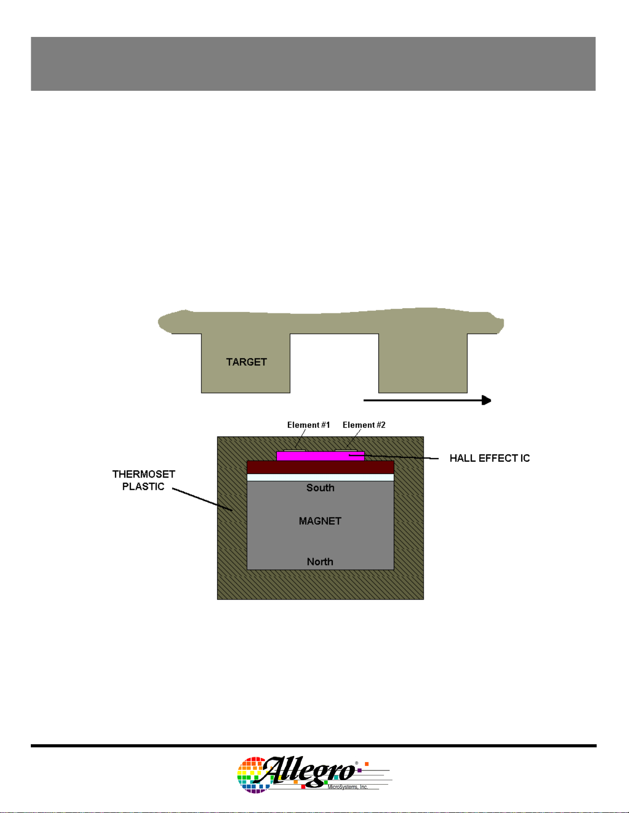
Sensing Technology:
The gear tooth sensor sub-assembly contains a single-chip differential Hall effect sensor IC, a Samarium Cobalt magnet,
and a flat ferrous pole piece. The Hall IC consists of two Hall elements spaced 2.2 mm apart which measure the magnetic
gradient created by the passing of a ferrous object. The gradient is converted to an analog voltage that is then processed
to provide a digital output signal.
Final Version, Rev 1.0; DSD; 01Aug03
Page 4
115 Northeast Cutoff, Box 15036
Worcester, Massachusetts 01615-0036 (508) 853-5000
Copyright © 1993, 1995 Allegro MicroSystems, Inc.

ATS665LSG
TRUE ZERO-SPEED GEAR TOOTH SENSOR
Operation:
After proper power is applied to the component the sensor is then capable of providing digital information that is
representative of the profile of a rotating gear. No additional optimization is needed and minimal processing circuitry is
required. This ease of use should reduce design time and incremental assembly costs for most applications. The following
output diagram is indicative of the sensor performance for the polarity indicated in the figure at the bottom of the page.
MECHANICAL PROFILE
MAGNETIC PROFILE
SENSOR ELECTRICAL OUTPUT PROFILE
Output Polarity:
The output of the sensor will switch from LOW to HIGH as the leading edge of the tooth passes the sensor face in the
direction indicated in the figure below. In this system configuration, the output voltage will be high when the sensor is facing
a tooth. If rotation occurs in the opposite direction, the output polarity will invert.
High over Tooth
Power-On State Operation:
The device is guaranteed to power up in the OFF state (logic high output).
Final Version, Rev 1.0; DSD; 01Aug03
Page 5
115 Northeast Cutoff, Box 15036
Worcester, Massachusetts 01615-0036 (508) 853-5000
Copyright © 1993, 1995 Allegro MicroSystems, Inc.

ATS665LSG
TRUE ZERO-SPEED GEAR TOOTH SENSOR
Start-up Detection:
Since the sensor powers up in the OFF state (logic high output), the first edge seen by the sensor can be missed if the
switching induced by that edge reinforces the OFF state. Therefore, the first edge that can be guaranteed to induce an
output transition is the second detected edge. This device has accurate first electrical falling edge detection. The tables
below show various start-up schemes.
MECHANICAL
TARGET PROFILE
MAGNETIC PROFILE
(High over Tooth)
SENSOR OUTPUT
(Start-up over Valley)
High over Tooth
SENSOR OUTPUT
(Start-up over Rising Edge)
Low over Tooth
SENSOR OUTPUT
(Start-up over Tooth)
SENSOR OUTPUT
(Start-up over Falling Edge)
MECHANICAL
TARGET PROFILE
MAGNETIC PROFILE
(Low over Tooth)
SENSOR OUTPUT
(Start-up over Valley)
SENSOR OUTPUT
(Start-up over Rising Edge)
Sensor start-up location
Final Version, Rev 1.0; DSD; 01Aug03
Page 6
SENSOR OUTPUT
(Start-up over Tooth)
SENSOR OUTPUT
(Start-up over Falling Edge)
Sensor start-up location
115 Northeast Cutoff, Box 15036
Worcester, Massachusetts 01615-0036 (508) 853-5000
Copyright © 1993, 1995 Allegro MicroSystems, Inc.

ATS665LSG
N
TRUE ZERO-SPEED GEAR TOOTH SENSOR
Under-Voltage Lockout:
When the supply voltage falls below the minimum operating voltage (Vcc
irrespective of the state of the magnetic field. This prevents false signals caused by under-voltage conditions from
propagating to the output of the sensor.
Power Supply Protection:
The device contains an on-chip regulator and can operate over a wide supply voltage range. For devices that need to
operate from an unregulated power supply, transient protection must be added externally. For applications using a
regulated line, EMI/RFI protection may still be required. The following circuit is the most basic configuration required for
proper device operation. For EMC information, contact your Allegro representative.
), the device turns OFF and stays OFF
UV
Internal Electronics:
The ATS665 contains a self-calibrating Hall effect IC that possesses two Hall elements, a temperature compensated
amplifier and offset cancellation circuitry. The IC also contains a voltage regulator that provides supply noise rejection over
the operating voltage range. The Hall transducers and the electronics are integrated on the same silicon substrate using a
proprietary BiCMOS process. Changes in temperature do not greatly affect this device due to the stable amplifier design
and the offset rejection circuitry.
Vcc
Vsig
INTERNAL
HALL AMP
AUTOMAT IC
GAIN
CONTROL
THRESHP
REFERENCE
GENERATOR
PDAC
PPEAK
THRESHN
REGULATOR
THRESHOLD
COMPAR ATOR
THRESH
LOGIC
OUTPUT
Output
Transisto
Current
Limit
DAC
NPEAK
GND
Final Version, Rev 1.0; DSD; 01Aug03
Page 7
115 Northeast Cutoff, Box 15036
Worcester, Massachusetts 01615-0036 (508) 853-5000
Copyright © 1993, 1995 Allegro MicroSystems, Inc.

ATS665LSG
TRUE ZERO-SPEED GEAR TOOTH SENSOR
SENSOR OPERATION: AUTOMATIC GAIN CONTROL (AGC)
The patented self-calibrating circuitry is unique. After each power up, the device measures the peak-to-peak magnetic
signal. The gain of the sensor is then adjusted which keeps the internal signal amplitude constant over the air gap range of
the device. This feature provides operational characteristics independent of air gap.
MAGNETIC FLUX DENSITY
DIFFERENTIAL MAGNETIC SIGNAL
WITH INCREASING AIR GAP
1000
800
600
400
200
0
-200
[GAUSS]
-400
-600
-800
-1000
0123456789101112131415
TARGET POSITION [DEGREES]
0.25 mm
0.50 mm
1.00 mm
1.50 mm
2.00 mm
DIFFERENTIAL SIGNAL [mV]
DIFFERENT IAL ELECT RICAL SIGNAL
WIT H INCREASING AIR GAP
1000
800
600
400
200
0
-200
-400
-600
-800
-1000
0123456789101112131415
TARGET POSITION [DEGREES]
0.25 mm
0.50 mm
1.00 mm
1.50 mm
2.00 mm
Magnetic Signal with no Amplification
Electrical Signal after AGC
SENSOR OPERATION: OFFSET ADJUST
In addition to normalizing performance over air gap, the gain control circuitry also reduces the effect of chip, magnet, and
installation offsets. This is accomplished using two D/A converters that capture the peak and valley of the signal and use it
as a reference for the switching comparator. If induced offsets bias the absolute signal up or down, AGC and the dynamic
DAC behavior work to normalize and reduce the impact of the offset on sensor performance.
Final Version, Rev 1.0; DSD; 01Aug03
Page 8
115 Northeast Cutoff, Box 15036
Worcester, Massachusetts 01615-0036 (508) 853-5000
Copyright © 1993, 1995 Allegro MicroSystems, Inc.

ATS665LSG
TRUE ZERO-SPEED GEAR TOOTH SENSOR
SENSOR OPERATION: SWITCHPOINTS
Switchpoints in the ATS665 are established dynamically as a percentage of the amplitude of the normalized magnetic
signal. Two DACs track the peaks of the normalized magnetic signal (see the section on Update); the switching thresholds
are established at 30% and 70% of the two DAC’s values. The proximity of the thresholds near 50% ensures the most
accurate and consistent switching where the signal is steepest and least affected by air gap variation.
The hysteresis of 40% provides high air gap performance and immunity to false switching on noise, vibration, backlash and
other transient events. Since the hysteresis value is independent of air gap, it provides protection against false switching in
the presence of overshoot that can be induced on the edges of large teeth.
The figure below graphically demonstrates the establishment of the switching threshold levels.
Switching Threshold Levels
Bop
100 %
70 %
30 %
0 %
Brp
Because the threshold are established dynamically as a percentage of the peak-peak signal, the effect of a baseline shift is
minimized. As a result, the effects of offsets induced by tilted or off-center installation are minimized.
Final Version, Rev 1.0; DSD; 01Aug03
Page 9
115 Northeast Cutoff, Box 15036
Worcester, Massachusetts 01615-0036 (508) 853-5000
Copyright © 1993, 1995 Allegro MicroSystems, Inc.

ATS665LSG
TRUE ZERO-SPEED GEAR TOOTH SENSOR
SENSOR OPERATION: UPDATE
The ATS665 incorporates an algorithm that continuously monitors the system and updates the switching thresholds
accordingly. The switch point for each edge is determined by the previous two edges. Since variations are tracked in real
time, the sensor has high immunity to target run-out and retains excellent accuracy and functionality in the presence of
both run-out and transient mechanical events. The figures below show how the sensor uses historical data to provide the
switching threshold for a given edge.
Switching Level - Operate
Operate point
based on previous
two peaks
Final Version, Rev 1.0; DSD; 01Aug03
Page 10
Switching Level - Release
Release point
based on previous
two peaks
115 Northeast Cutoff, Box 15036
Worcester, Massachusetts 01615-0036 (508) 853-5000
Copyright © 1993, 1995 Allegro MicroSystems, Inc.

ATS665LSG
TRUE ZERO-SPEED GEAR TOOTH SENSOR
SENSOR/TARGET EVALUATION
In order to establish the proper operating specification for a particular sensor/target system, a systematic evaluation of the
magnetic circuit should be performed. The first step is the generation of a magnetic map of the target. By using a
calibrated device, a magnetic signature of the system is made. The following is a map of the 60-0 reference target. Flux
density shown is the differential of the magnetic fields sensed at the two Hall elements.
300
250
200
150
100
50
0
-50
-100
Flux Density [Gauss]
-150
-200
0.94mm
1.19mm
1.44mm
1.69mm
1.94mm
2.19mm
2.44mm
2.69mm
2.94mm
3.19mm
-250
-300
0 5 10 15 20 25 30 35
Position [º]
A single curve is distilled from this map data that describes the peak-peak magnetic field versus air gap. Knowing the
minimum amount of magnetic flux density that guarantees operation of the sensor, one can determine the maximum
operational air gap of the sensor/target system. Referring to the chart below, a minimum required peak-peak signal of 60G
corresponds to a maximum air gap of approximately 2.5 mm.
ATS665LSG 60-0 TARGET MAP
700
600
500
400
300
200
Peak-Peak Flux Density [Gauss]
100
0
0.511.522.533
Final Version, Rev 1.0; DSD; 01Aug03
Page 11
Air Gap [mm]
.5
115 Northeast Cutoff, Box 15036
Worcester, Massachusetts 01615-0036 (508) 853-5000
Copyright © 1993, 1995 Allegro MicroSystems, Inc.

ATS665LSG
TRUE ZERO-SPEED GEAR TOOTH SENSOR
TARGET DESIGN
For the generation of adequate magnetic field levels to maximize air gap performance, the following recommendations
should be followed in the design and specification of targets.
• Tooth width > 2 mm
• Valley width > 2 mm
• Valley depth > 2 mm
• Gear thickness > 3 mm
• Target material must be low carbon steel
Though these parameters apply to targets of traditional geometry (radially oriented teeth with radial sensing), they can be
applied to stamped targets as well. For stamped geometries with axial sensing, the valley depth is intrinsically infinite so
the criteria for tooth width, valley width, material thickness (can be < 3 mm) and material specification need only be
considered.
SENSOR EVALUATION: ACCURACY
While the update algorithm will allow the sensor the adapt to system changes (i.e. air gap increase), major changes in air
gap can adversely affect switching performance. When characterizing sensor performance over a significant air gap range,
be sure to re-power the device at each air gap. This ensures that self-calibration occurs for each installation condition.
See the section entitled Characteristic Data for typical duty cycle performance.
Final Version, Rev 1.0; DSD; 01Aug03
Page 12
115 Northeast Cutoff, Box 15036
Worcester, Massachusetts 01615-0036 (508) 853-5000
Copyright © 1993, 1995 Allegro MicroSystems, Inc.

ATS665LSG
TRUE ZERO-SPEED GEAR TOOTH SENSOR
POWER DE-RATING
Due to internal power consumption, the junction
temperature of the IC, Tj, is higher than the ambient
environment temperature, Ta. To ensure that the device
does not operate above the maximum rated junction
temperature use the following calculations:
∆T = PD * Rθja
Where: P
Where ∆T denotes the temperature rise resulting from
the IC’s power dissipation.
For the sensor :
Typical Tj calculation:
Vcc = 5 V
Icc = 7.0 mA
P
∆T = P
Tj = Ta + ∆T = 25 °C + 5.0°C = 30.0°C
Maximum Allowable Power Dissipation Calculation
for ATS665:
Assume:
Ta = Ta
Tj(max) = 165°C
Icc = 12.0 mA4
If:
4
max Icc @ 150C < max Icc @ 25C, see characteristic
data
= Vcc * Icc
D
∴ ∆T=Vcc * Icc * Rθja
Tj = Ta + ∆T
Tj(max) = 165°C
Rθja = 126°C/W
Ta = 25 °C
= Vcc * Icc = 5 V * 8.0 mA = 40.0 mW
D
* Rθja = 40.0 mW * 126°C/W = 5.0°C
D
= 165 °C
max
Tj = Ta + ∆T
Then, at Ta = 150 °C:
∆T
max
= Tj
max
– Ta
= 165°C - 150°C = 15°C
max
If:
∆T = P
* Rθja
D
Then, at Ta = 150°C:
P
Dmax
= ∆T
/ Rθja = 15°C / 126°C/W = 119 mW
max
If:
P
= Vcc * Icc
D
Then the maximum Vcc at 150°C is therefore:
Vccmax = P
/ Icc = 119 mW / 12.0 mA = 9.9 V
Dmax
This value applies only to the voltage drop across the
665 chip. If a protective series diode or resistor is used,
the effective maximum supply voltage is increased.
For example, when a standard diode with a 0.7 V drop is
used:
Vsmax = 9.9 V + 0.7 V = 10.6 V
ATS665LSG Package Power De-Rating Curve
The rm a l R e si st a nce = 126°C/ W a tt, T
30.0
28.0
26.0
24.0
22.0
20.0
18.0
16.0
14.0
12.0
10.0
8.0
6.0
4.0
Maximum Supply Voltage [Volts]
2.0
0.0
20 40 60 80 100 120 140 160 180
Ambient Temperature [°C]
c
jmax
= 165°C
Final Version, Rev 1.0; DSD; 01Aug03
Page 13
115 Northeast Cutoff, Box 15036
Worcester, Massachusetts 01615-0036 (508) 853-5000
Copyright © 1993, 1995 Allegro MicroSystems, Inc.

ATS665LSG
TRUE ZERO-SPEED GEAR TOOTH SENSOR
CHARACTERISTIC DATA
IccOn
14
12
10
8
6
Icc [mA]
4
2
0
0102030
Vcc [V]
IccOff
14
12
10
8
6
Icc [mA]
4
2
0
0102030
Vcc [V]
Vsat
400
350
°C
°C
-40
0
25
85
150
-40
0
25
85
150
IccOn
14
12
10
8
6
Icc [mA]
4
2
0
-50 0 50 100 150
Temperature [°C]
4.3
12
20
26.5
Vcc
IccOff
14
12
10
8
6
Icc [mA]
4
2
0
-50 0 50 100 150
Temperature [°C]
4.3
12
20
26.5
Vcc
300
250
200
150
Output Voltage [mV]
100
50
-50 0 50 100 150 200
Temperature [°C]
Final Version, Rev 1.0; DSD; 01Aug03
Page 14
115 Northeast Cutoff, Box 15036
Worcester, Massachusetts 01615-0036 (508) 853-5000
Copyright © 1993, 1995 Allegro MicroSystems, Inc.

ATS665LSG
TRUE ZERO-SPEED GEAR TOOTH SENSOR
CHARACTERISTIC DATA (Continued)
Duty Cycle 100 RPM
53
52
51
50
49
48
47
46
Duty Cycle [%]
45
44
43
-50 0 50 100 150
Temperature [°C]
Duty Cycle 1000 RPM
53
52
51
50
49
48
47
46
Duty Cycle [%]
45
44
43
-50 0 50 100 150
Temperature [°C]
Air
gap
Air
gap
0.4
0.5
0.8
1.5
2.35
2.5
0.4
0.5
0.8
1.5
2.35
2.5
Duty Cycle 100 RPM
53
52
51
50
49
48
47
46
Duty Cycle [%]
45
44
43
0123
Air Gap [mm]
-40
0
25
85
150
°C
Duty Cycle @ 1000 RPM
53
52
51
50
49
48
47
46
Duty Cycle [%]
45
44
43
0123
Air Gap [mm]
-40
0
25
85
150
°C
Final Version, Rev 1.0; DSD; 01Aug03
Page 15
115 Northeast Cutoff, Box 15036
Worcester, Massachusetts 01615-0036 (508) 853-5000
Copyright © 1993, 1995 Allegro MicroSystems, Inc.

ATS665LSG
TRUE ZERO-SPEED GEAR TOOTH SENSOR
PACKAGE DRAWING
Final Version, Rev 1.0; DSD; 01Aug03
Page 16
115 Northeast Cutoff, Box 15036
Worcester, Massachusetts 01615-0036 (508) 853-5000
Copyright © 1993, 1995 Allegro MicroSystems, Inc.

ATS665LSG
TRUE ZERO-SPEED GEAR TOOTH SENSOR
RELATED DOCUMENTS
Documents that can be found on the Allegro Microsystems web site: www.allegromicro.com :
• Definition of Terms (Pub 26004)
• Hall-Effect Devices: Soldering, Gluing, Potting, Encapsulating, and Lead Forming (AN27703.1)
• Storage of Semiconductor Devices (Pub 26011)
Hall Effect Applications Guide (Pub 27701)
•
Applications Note: Back-Biased Packaging Advances (SE, SG & SH versus SA & SB) •
Additional Applications Information on gear tooth and other Allegro sensors can be obtained at Allegro’s web
site, www.allegromicro.com
Final Version, Rev 1.0; DSD; 01Aug03
Page 17
115 Northeast Cutoff, Box 15036
Worcester, Massachusetts 01615-0036 (508) 853-5000
Copyright © 1993, 1995 Allegro MicroSystems, Inc.

ATS665LSG
TRUE ZERO-SPEED GEAR TOOTH SENSOR
Final Version, Rev 1.0; DSD; 01Aug03
Page 18
115 Northeast Cutoff, Box 15036
Worcester, Massachusetts 01615-0036 (508) 853-5000
Copyright © 1993, 1995 Allegro MicroSystems, Inc.
 Loading...