


查询ATS642LSH供应商
ATS642LSH
Two-Wire True Zero Speed Miniature Differential
Peak-Detecting Gear Tooth Sensor with Continuous Calibration
The ATS642LSH is an optimized Hall effect sensing integrated circuit and magnet
combination that provides a user-friendly solution for true zero-speed digital
gear-tooth sensing in two-wire applications. The sensor consists of a single-shot
Package SH, 4-pin Module
1
2
3
4
1. VCC
2. No connection
3. Test pin (fl oat or tie to GND)
4. GND
molded plastic package that includes a samarium cobalt magnet, a pole piece,
and a Hall effect IC that has been optimized to the magnetic circuit. This small
package, with optimized two-wire leadframe, can be easily assembled and used in
conjunction with a wide variety of gear shapes and sizes.
The integrated circuit incorporates a dual element Hall effect sensor and signal
processing that switches in response to differential magnetic signals created
by ferrous gear teeth. The circuitry contains a sophisticated digital circuit to
reduce magnet and system offsets, to calibrate the gain for air gap independent
switchpoints, and to achieve true zero-speed operation. Signal optimization occurs
at power-up through the combination of offset and gain adjust and is maintained
throughout the operating time with the use of a running mode calibration. The running mode calibration allows immunity to environmental effects such as microoscillations of the target or sudden air gap changes.
The regulated current output is configured for two wire applications and the
sensor is ideally suited for obtaining speed and duty cycle information in ABS
(antilock braking systems). The 1.5 mm Hall element spacing is optimized for fine
pitch gear-tooth-based configurations. The package is lead (Pb) free, with 100%
matte tin leadframe plating.
AB SO LUTE MAX I MUM RAT INGS
Supply Voltage, V
Reverse-Supply Voltage, V
Operating Temperature
Ambient, T
Maximum Junction, T
Storage Temperature, T
ATS642LSH-DS
..........................................28 V
CC
,............................... –40ºC to 150ºC
A
........................–18 V
RCC
........................165ºC
J(max)
.................. –65ºC to 170ºC
S
Features and Benefi ts
• Running mode calibration for continuous optimization
• Single chip IC for high reliability
• Internal current regulator for 2-wire
operation
• Small mechanical size (8 mm
diameter x 5.5 mm depth)
• Precise duty cycle signal over
operating temperature range
Use the following complete part numbers when ordering:
Part Number ICC Typical Packing*
ATS642LSHTN-I1-T 6.0 Low to 14.0 High mA
ATS642LSHTN-I2-T 7.0 Low to 14.0 High mA
*Contact Allegro for additional packing options.
• Large operating air gaps
• Automatic Gain Control (AGC)
gap independent switchpoints
• Automatic Offset Adjustment (AOA)
for signal processing optimization
• True zero-speed operation
• Undervoltage lockout
• Wide operating voltage range
Allegro MicroSystems, Inc.
115 Northeast Cutoff, Box 15036
Worcester, Massachusetts 01615-0036 (508) 853-5000
www.allegromicro.com
for air
Tape and reel,
13-inch reel
800 pieces/reel
ATS642LSH
C
D
True Zero Speed Miniature Differential Peak-Detecting Gear Tooth Sensor
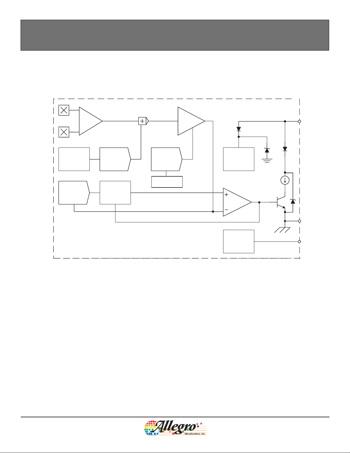
Functional Block Diagram
Amplifier
Automatic Offset
Control
Tracking
DAC
Hall
AOA DAC
Peak Hold
AGC DAC
Gain Control
Gain
Internal Regulator
Test Signals
VC
GN
Test
ATS642LSH-DS
Allegro MicroSystems, Inc.
115 Northeast Cutoff, Box 15036
Worcester, Massachusetts 01615-0036 (508) 853-5000
www.allegromicro.com
2

ATS642LSH
True Zero Speed Miniature Differential Peak-Detecting Gear Tooth Sensor
OPERATING CHARACTERISTICS using reference target 60-0, T
and VCC within specifi cation, unless otherwise noted
A
CHARACTERISTIC Symbol Test Conditions Min. Typ.
ELECTRICAL CHARACTERISTICS
Supply Voltage
2
Undervoltage Lockout V
Supply Zener Clamp Voltage V
Supply Zener Current I
V
CC(UV) VCC
Operating; TJ < 165 °C 4.0 – 24 V
CC
I
Z
CC
Test conditions only; VZ = 28 V – –
Z
0 → 5 V and 5 → 0 V – – 4.0 V
= I
+ 3 mA; TA = 25°C 28 – – V
CC(max)
ATS642LSH-I1 4.0 6.0 8.0 mA
I
CC(Low)
ATS642LSH-I2 5.9 7.0 8.4 mA
Supply Current
ATS642LSH-I1 12.0 14.0 16.0 mA
I
I
Supply Current Ratio
CC(High)
I
Reverse Battery Current I
CC(High)
CC(Low)
RCC
ATS642LSH-I2 11.8 14.0 16.8 mA
/
Ratio of high current to low current 1.85 – 3.05 –
V
= –18 V – – –5 mA
RCC
POWER-ON STATE CHARACTERISTICS
Power-On State
Power-On Time
3
4
POS t > t
t
Target gear speed < 100 rpm – 1 2 ms
PO
PO
OUTPUT STAGE
Output Slew Rate
5
dI/dt R
= 100 Ω, C
LOAD
= 10 pF – 10 – mA/μs
LOAD
–I
CC(High)
1
Max. Units
I
CC(max)
3 mA
+
mA
––
Continued on the next page.
ATS642LSH-DS
Allegro MicroSystems, Inc.
115 Northeast Cutoff, Box 15036
Worcester, Massachusetts 01615-0036 (508) 853-5000
www.allegromicro.com
3

ATS642LSH
True Zero Speed Miniature Differential Peak-Detecting Gear Tooth Sensor
OPERATING CHARACTERISTICS (continued) using reference target 60-0, T
Characteristic Symbol Test Conditions Min. Typ.
and VCC within specifi cation, unless otherwise noted
A
1
Max. Units
SWITCHPOINT CHARACTERISTICS
Rotation Speed S
Reference Target 60-0 0 – 8,000 rpm
ROT
Analog Signal Bandwidth BW Equivalent to f – 3 dB 20 40 – kHz
Operate Point B
Release Point B
Transitioning from I
OP
referenced; AG < AG
Transitioning from I
RP
referenced; AG < AG
CC(High)
MAX
CC(Low)
MAX
to I
to I
CC(Low)
CC(High)
; positive peak
; negative peak
– 120 – mV
– 120 – mV
CALIBRATION
Initial Calibration C
Quantity of rising output (current) edges required for
I
accurate edge detection
– – 3 Edge
DAC CHARACTERISTICS
Allowable User-Induced Differential
Offset
FUNCTIONAL CHARACTERISTICS
Operational Air Gap Range
7
Maximum Operational Air Gap
Range
6
AG ΔDC within specifi cation 0.5 – 2.75 mm
AG
OP(max)
Duty Cycle Variation ΔDC
Duty Cycle Pitch Variance
Operating Signal Range
Minimum Operating Signal Sig
1
Typical values are at TA = 25°C and VCC = 12 V. Performance may vary for individual units, within the specifi ed maximum and minimum limits.
2
Maximum voltage must be adjusted for power dissipation and junction temperature; see Power Derating section.
3
Please refer to Sensor Operation section, page 13.
4
Power-On Time includes the time required to complete the internal automatic offset adjust. The DACs are then ready for peak acquisition.
5
dI is the difference between 10% of I
Note: di/dt is dependent upon the value of the bypass capacitor, if one is used.
6
Functional characteristics valid only if magnetic offset is within the specifi ed range for Allowable User Induced Differential Offset.
7
AG is dependent on the available magnetic fi eld. The available fi eld is dependent on target geometry and material, and should be independently
characterized. The fi eld available from the reference target is given in the reference target parameter section of the datasheet.
8
E
represents the difference between consecutive duty cycles, DC(n) - DC(n-1); Mean ± 3-sigma.
DC
9
In order to remain in specifi cation, the magnetic gradient must induce an operating signal greater than the minimum value specifi ed. This includes the
effect of target wobble.
8
9
E
Sig Operating within specifi cation 30 – 1000 G
OP(min)
and 90% of I
CC(Low)
Output switching only; may not meet datasheet specifi cations
Output switching (no missed edges); ΔDC not
guaranteed
Wobble < 0.5 mm; Typical value at AG = 1.5 mm, for
max., min., AG within specifi cation
AG = 1.5 mm – ±1.5 – %
DC
Output switching (no missed edges); ΔDC not
guaranteed
, and dt is time period between those two points.
CC(High)
– ±60 – G
––3mm
41 – 61 %
20 – – G
ATS642LSH-DS
Allegro MicroSystems, Inc.
115 Northeast Cutoff, Box 15036
Worcester, Massachusetts 01615-0036 (508) 853-5000
www.allegromicro.com
4
ATS642LSH
D
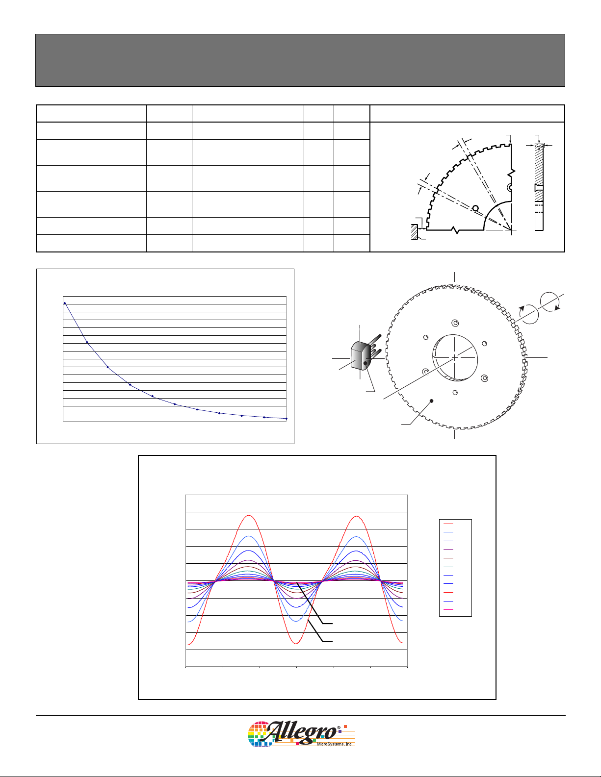
o
h
t
F
Air Gap
Branded Face of Sensor
t
t
v
Reference Target
60-0
of Sensor
Branded Face
True Zero Speed Miniature Differential Peak-Detecting Gear Tooth Sensor
REFERENCE TARGET, 60-0 (60 Tooth Target)
Characteristics Symbol Test Conditions Typ. Units Symbol Key
Outside Diameter D
Face Width F
Angular Tooth Thickness t
Angular Valley Thickness t
Tooth Whole Depth h
Outside diameter of target
o
Breadth of tooth, with
respect to sensor
Length of tooth, with
respect to sensor
Length of valley, with
v
respect to sensor
t
120 mm
6mm
3 deg
3 deg
3mm
Material Low Carbon Steel – –
Reference Gear Magnetic Gradient Amplitude
800
700
600
500
400
300
200
Peak-to-Peak Differential B (G)
100
0
With Reference to Air Gap
11.520.5 2.5 3
Air Gap (mm)
ATS642LSH-DS
Reference Gear Magnetic Profile
Two Tooth-to-Valley Transitions
500
400
300
200
100
0
-100
-200
Differential B* (G)
3.00 mm AG
-300
0.50 mm AG
-400
-500
024681012
Gear Rotation (°)
Air Gap
(mm)
0.50
0.75
1.00
1.25
1.50
1.75
2.00
2.25
2.50
2.75
3.00
Allegro MicroSystems, Inc.
115 Northeast Cutoff, Box 15036
Worcester, Massachusetts 01615-0036 (508) 853-5000
www.allegromicro.com
5
 Loading...