

Allegro ATS632LSA Datasheet
ATS632LSA
HALL-EFFECT
GEAR-TOOTH SENSOR
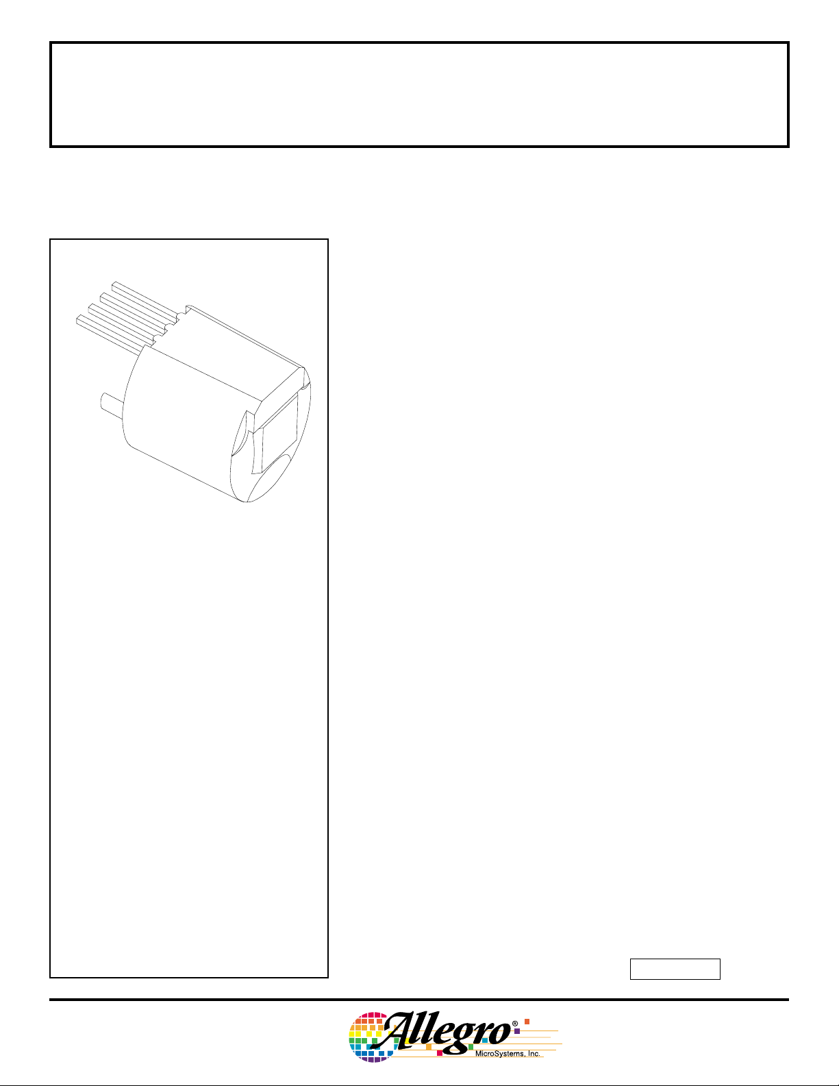
SUBASSEMBLY
NON-ORIENTED, HALL-EFFECT GEAR-TOOTH SENSOR
1
2
3
4
Pin 1 = Supply
Pin 2 = Output
Pin 3 = Test Point
Pin 4 = Ground
PRELIMINARY INFORMATION
(subject to change without notice)
December 2, 1998
Dwg. AH-006-2
ATS632LSA
ZERO-SPEED, SELF-CALIBRATING,
The ATS632LSA gear-tooth sensor is an optimized Hall-effect IC/
magnet combination that provides extremely accurate tooth edge
detection when used with large-pitch targets. The sensor subassembly
consists of a high-temperature plastic shell that holds together a
compound samarium-cobalt magnet and a single-element self-calibrating Hall-effect IC that has been optimized to the magnetic circuit. This
small package, with its non-oriented operation, can be easily assembled on a PC board for complete protection and used in conjunction with a number of gear configurations.
The gear sensing technology used for this sensor subassembly is
Hall-effect based. The sensor incorporates a single-element Hall IC
that switches in response to absolute magnetic signals created by a
ferrous target. The digital output is LOW over a tooth and HIGH over a
valley. The sophisticated processing circuitry contains self-calibrating
6-bit A/D circuitry that adapts the thresholds to the peak-to-peak
signals to minimize the effects of variation in application air gap on
switch-point timing accuracy. The effects of system and device offsets
are minimized by using active offset cancellation circuitry. The digital
algorithm provides zero-speed detection capabilities without the
associated running jitter inherent in classical digital solutions.
Data Sheet
27627.125
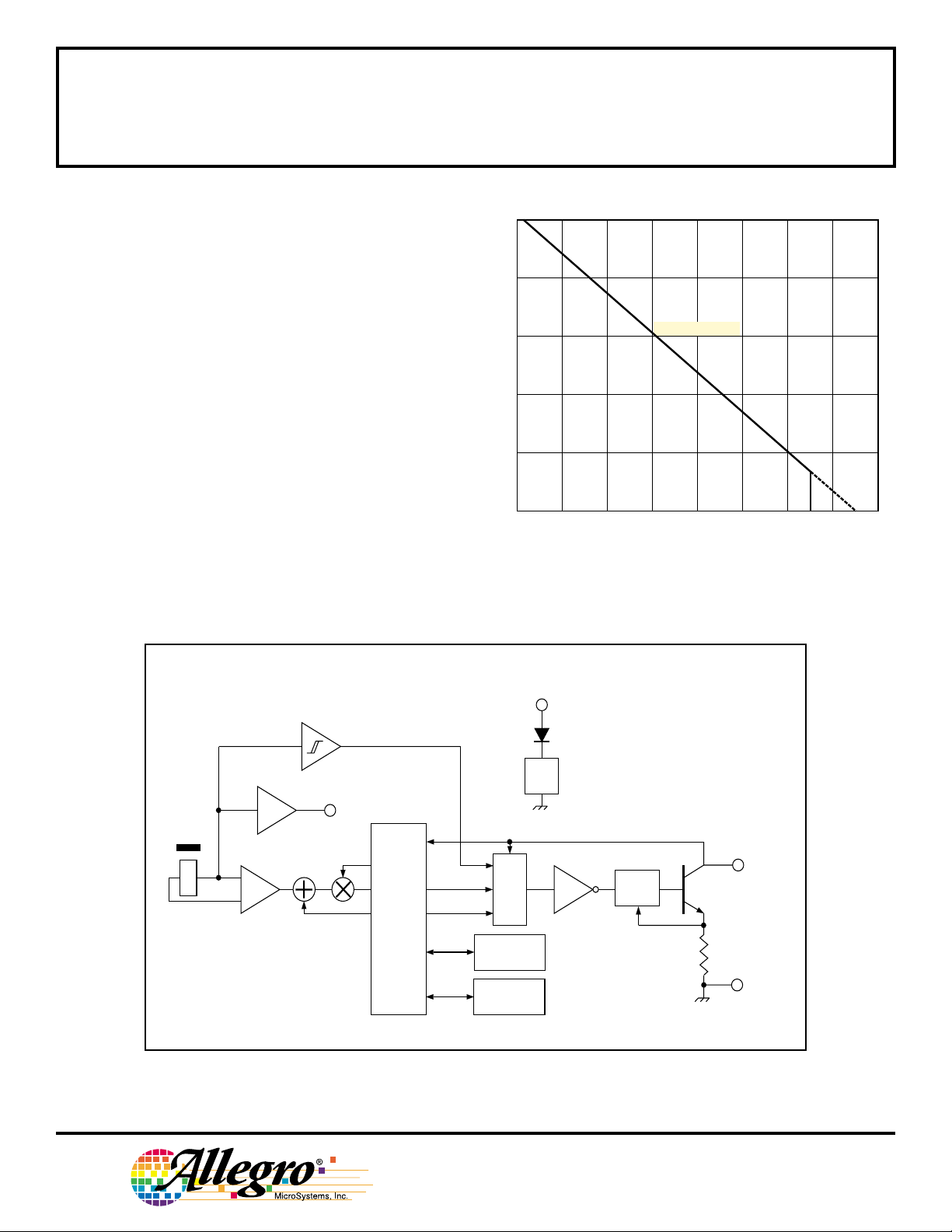
ABSOLUTE MAXIMUM RATINGS
Supply Voltage, VCC.........................24 V*
Reverse Supply Voltage, V
Output OFF Voltage, V
Output Current, I
Reverse Output Current, I
Package Power Dissipation,
.................................... See Graph
P
D
Operating Temperature Range,
............................ -40°C to +150°C
T
A
Storage Temperature, TS............ +170°C
* Operation at increased supply voltages with
external circuitry is described in Applications
Information.
OUT
.. Internally Limited
OUT
........ -24 V
RCC
................. 25 V
........ 50 mA
OUT
This sensor system is ideal for use in gathering speed, position
and profile information of ferrous objects. They are particularly suited
to large tooth/valley sensing applications where accurate timing
accuracy is a desired feature. For applications requiring the sensing of
fine-pitch gears, the ATS610LSA and ATS611LSB are recommended.
continued next page…
Always order by complete part number, e.g., ATS632LSA .
ATS632LSA
ALLOWABLE PACKAGE POWER DISSIPATION IN mW
HALL-EFFECT
GEAR-TOOTH SENSOR
SUBASSEMBLY
FEATURES AND BENEFITS
■ Non-Oriented Installation
■ Fully Optimized Gear-Tooth Sensors
■ Zero-Speed Digital Output Representing Target
Profile
■ Large Operating Air Gaps
■ Extremely Low Timing Accuracy Drift with Tempera-
ture
■ Correct First-Edge Detection
■ Self-Calibrating Circuitry
with Integrated Offset Cancellation
6-bit A/D Converters to Capture Peaks
Thresholds Proportional to Peak-to-Peak Signals
■ Optimized Magnetic Circuit
■ Single-Chip Sensing IC for High Reliability
1000
800
600
400
200
RθJA = 147°C/W
0
40 80 120
60 100 140 18020
AMBIENT TEMPERATURE IN °C
160
Dwg. GH-065-1
MAGNET
X
FUNCTIONAL BLOCK DIAGRAM
SUPPLY
1
POWER ON
REG
TEST
3
POINT
GAIN
–
+
OFFSET
REFERENCE
GENERATOR
THRESHOLD
PEAK
LOGIC
OUTPUT
POSITIVE PEAK
TRACK & HOLD
NEGATIVE PEAK
TRACK & HOLD
CURRENT
LIMIT
2
OUTPUT
4
GROUND
Dwg. FH-015-2
115 Northeast Cutoff, Box 15036
Worcester, Massachusetts 01615-0036 (508) 853-5000
W
Copyright © 1998, Allegro MicroSystems, Inc.

ATS632LSA
HALL-EFFECT
GEAR-TOOTH SENSOR
SUBASSEMBLY
ELECTRICAL CHARACTERISTICS over operating voltage and temperature range (unless
otherwise specified).
Limits
Characteristic Symbol Test Conditions Min. Typ. Max. Units
Supply Voltage V
Under-Voltage Lockout V
Low Output Voltage V
Output Current Limit I
Output Leakage Current I
Supply Current I
Calibration Count n
CC
CC(UV)
OUT(L)
OUTM
OFF
CC
cal
Operating, TJ < 165°C 4.5 – 24 V
I
= 20 mA, VCC = 0 → 5 V – 4.0 – V
OUT
I
= 20 mA, Output ON – 0.2 0.4 V
OUT
V
= 12 V 25 45 55 mA
OUT
V
= 24 V, Output OFF – 0.2 5.0 µA
OUT
Output OFF, Target Speed = 0 RPM – 9.0 15 mA
Output falling mechanical edges 16 16 16 Pulses
after power on for startup calibration
to be complete
Calibration Update n
up
Output falling mechanical edges 64 64 64 Pulses
for the threshold calibration to be
complete
Power-On Time t
Output Rise Time t
Output Fall Time t
NOTE: Typical data is at VCC = 12 V and TA = +25°C and is for design information only.
po
r
f
VCC > 4.5 V – 80 500 µs
RL = 500 Ω, CL = 10 pF – 0.2 5.0 µs
RL = 500 Ω, CL = 10 pF – 0.2 5.0 µs

ATS632LSA
HALL-EFFECT
GEAR-TOOTH SENSOR
SUBASSEMBLY
OPERATION over operating voltage and temperature range with reference target (unless otherwise specified).
Limits
Characteristic Symbol Test Conditions Min. Typ. Max. Units
Operating Air Gap Range AG Operating, 0.3 – 2.5 mm
Target Speed > 20 RPM
Output Polarity – Operating, Over Tooth Low Low Low –
Operating, Over Valley High High High –
Timing Accuracy t
θ
Target Speed < 3500 RPM, – ±0.25 ±0.50 °
0.3 mm ≤ AG ≤ 2.0 mm
TARGET DESIGN CRITERIA
Limits
Characteristic Symbol Description Min. Typ. Max. Units
Valley Depth h
Valley Width (P
Tooth Width T – 5.0 – mm
Thickness F – 5.0 – mm
Eccentricity – Timing accuracy may change ––±0.25 mm
t
- T) – 5.0 – mm
C
– 5.0 – mm
TARGET DIMENSIONS
Diameter Thickness Tooth Width Valley Width Valley Depth
Type (D
Reference Target 84 mm 16 mm 9 mm 13 mm 5 mm
Characterization Target #1 84 mm 16 mm 1 tooth, 180° 5 mm
Characterization Target #2 35 mm 7 mm 1 tooth, 180° 6 mm
NOTE: Timing accuracy data is taken by recalibrating the unit at each air gap.
) (F) (T) (PC - T) (ht)
o
115 Northeast Cutoff, Box 15036
Worcester, Massachusetts 01615-0036 (508) 853-5000
 Loading...