

Allegro ATS612JSB Datasheet
ATS612JSB
DYNAMIC, SELF-CALIBRATING, PEAK-DETECTING,
DIFFERENTIAL HALL-EFFECT GEAR-TOOTH SENSOR
ATS612JSB
Data Sheet
27627.109
PRELIMINARY INFORMATION
(subject to change without notice)
November 20, 1998
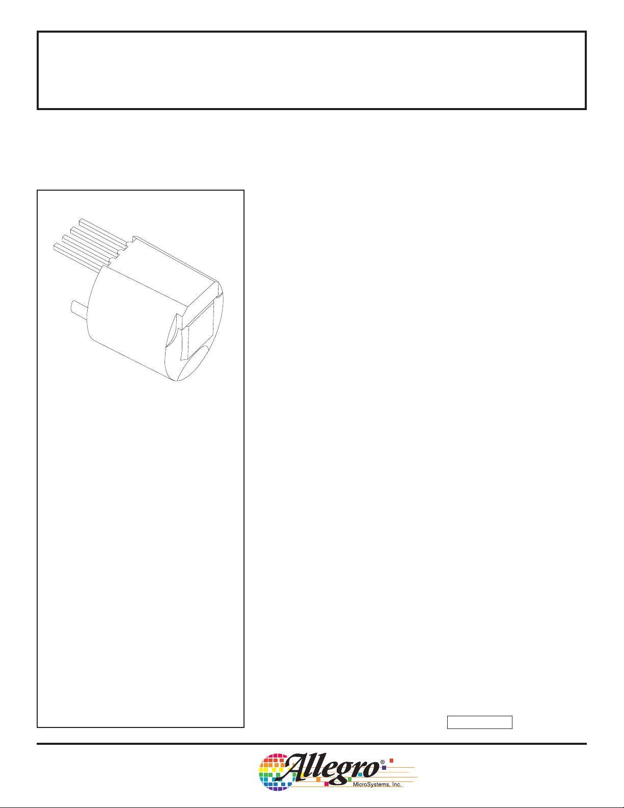
1
2
3
4
Pin 1 = Supply
Pin 2 = Output
Pin 3 = Capacitor
Pin 4 = Ground
Dwg. AH-006
DYNAMIC, SELF-CALIBRATING,
PEAK-DETECTING, DIFFERENTIAL
HALL-EFFECT GEAR-TOOTH SENSOR
The ATS612JSB dynamically-coupled gear tooth sensor is a peak
detecting device that uses gain control to provide extremely accurate
gear edge detection down to low operating speeds. Each sensor
subassembly consists of a high-temperature plastic shell that holds
together a samarium-cobalt magnet, a pole piece, and a dynamicallycoupled differential open-collector Hall IC that has been optimized to
the magnetic circuit. This small package can be easily assembled and
used in conjunction with a wide variety of gear shapes and sizes.
The gear-sensing technology used for this sensor subassembly is
Hall-effect based. The sensor incorporates a dual-element Hall IC that
switches in response to differential magnetic signals created by ferrous
targets. The sophisticated processing circuitry contains a self-calibrating 5-bit A/D converter that normalizes the internal gain of the device to
minimize the effect of air gap variations. The patented peak-detecting
filter circuit eliminates magnet and system offsets and has the ability to
discriminate relatively fast changes such as those caused by tilt, gear
wobble, and eccentricities yet provides stable operation to extremely
low RPMs.
ABSOLUTE MAXIMUM RATINGS
over operating temperature range
Supply Voltage, VCC...............................24 V*
Reverse Supply Voltage, V
Output OFF Voltage, V
Continuous Output Current,
............................ Internally Limited
I
OUT
Reverse Output Current, I
Package Power Dissipation,
.......................................... See Graph
P
D
Operating Temperature Range,
................................. -40°C to +115°C*
T
A
Storage Temperature, TS.................. +170°C
* Operation at increased supply voltages with
external circuitry is described in Applications
Information. Devices for operation at increased
temperatures are available on special order.
OUT
.............. -16 V
RCC
....................... 24 V
............ 50 mA
ROUT
These sensor systems are ideal for use in gathering speed, position, and timing information using gear-tooth-based configurations. The
ATS612JSB is particularly suited to those applications that require
extremely accurate duty cycle control or accurate edge detection similar
to crank shaft applications. The lower vibration sensitivity also makes
this device extremely useful for transmission speed sensing.
ATS612JSB: Large- or small-tooth gear-position sensing —
crank angle, transmission speed, cam angle.
continued next page…
Always order by complete part number: ATS612JSB .
ATS612JSB
DYNAMIC, SELF-CALIBRATING, PEAK-DETECTING,
DIFFERENTIAL HALL-EFFECT GEAR-TOOTH SENSOR
FEATURES AND BENEFITS
■ Fully Optimized Differential Digital Gear-Tooth Sensor
■ Single-Chip Sensing IC for High Reliability
■ Digital Output Representing Target Profile
■ Extremely Low Timing Accuracy Drift with Temperature
■ Large Operating Air Gaps
■ Small Mechanical Size
■ Optimized Magnetic Circuit
■ Patented Peak-Detecting Filter:
80 µs Typical Power-On Time
<10 RPM Operation (single-tooth target)
Correct First-Edge Detection
Uses Small Value Ceramic Capacitors
■ Under-Voltage Lockout
■ Wide Operating Voltage Range
■ Defined Power-On State
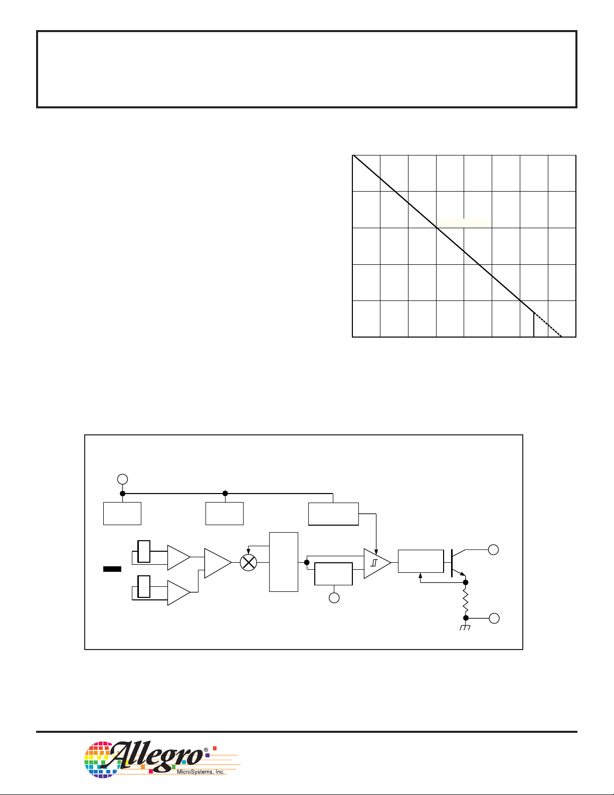
1000
800
R
θJA
600
400
200
0
ALLOWABLE PACKAGE POWER DISSIPATION IN mW
40 80 120
60 100 140 18020
AMBIENT TEMPERATURE IN °C
= 150°C/W
160
Dwg. GH-065-3
1
REG
MAGNET
Dwg. FH-014-1
SUPPLY
X
X
E1
E2
FUNCTIONAL BLOCK DIAGRAM
UVLO
GAIN
+
–
REFERENCE
POWER-ON
LOGIC
TRACK &
GENERATOR
HOLD
3
CAPACITOR
+
–
OUTPUT
2
CURRENT
LIMIT
GROUND
4
115 Northeast Cutoff, Box 15036
Worcester, Massachusetts 01615-0036 (508) 853-5000
W
Copyright © 1998, Allegro MicroSystems, Inc.

ATS612JSB
DYNAMIC, SELF-CALIBRATING, PEAK-DETECTING,
DIFFERENTIAL HALL-EFFECT GEAR-TOOTH SENSOR
ELECTRICAL CHARACTERISTICS over operating voltage and temperature range,
C3 = 0.1
Characteristic Symbol Test Conditions Min. Typ. Max. Units
µF to 0.47 µF.
Limits
Supply Voltage V
Power-On State POS VCC = 0 → 5 V HIGH HIGH HIGH –
Under-Voltage Lockout V
Under-Voltage Hysteresis V
Low Output Voltage V
Output Current Limit I
Output Leakage Current I
Supply Current I
Power-On Delay t
Output Rise Time t
Output Fall Time t
NOTE: Typical data is at VCC = 8 V and TA = +25°C and is for design information only.
CC
CC(UV)
CC(hys)
OUT(SAT)
OUTM
OFF
CC
on
r
f
Operating, TJ < 165°C 3.6 – 24 V
I
= 20 mA, VCC = 0 → 5 V 2.5 – 3.6 V
OUT
Lockout (V
I
OUT
V
OUT
V
OUT
Output OFF 6.0 8.2 12 mA
Output ON 8.0 10 14 mA
VCC > 5 V – 80 500 µs
RL = 500 Ω, CL = 10 pF – 0.2 5.0 µs
RL = 500 Ω, CL = 10 pF – 0.2 5.0 µs
CC(UV)
= 20 mA – 190 400 mV
= 12 V 25 45 55 mA
= 24 V – 0.2 15 µA
) – Shutdown – 0.2 – V
ATS612JSB
DYNAMIC, SELF-CALIBRATING, PEAK-DETECTING,
DIFFERENTIAL HALL-EFFECT GEAR-TOOTH SENSOR
OPERATION over operating voltage and temperature range with reference target
(unless otherwise specified).
Limits
Characteristic Symbol Test Conditions Min. Typ. Max. Units
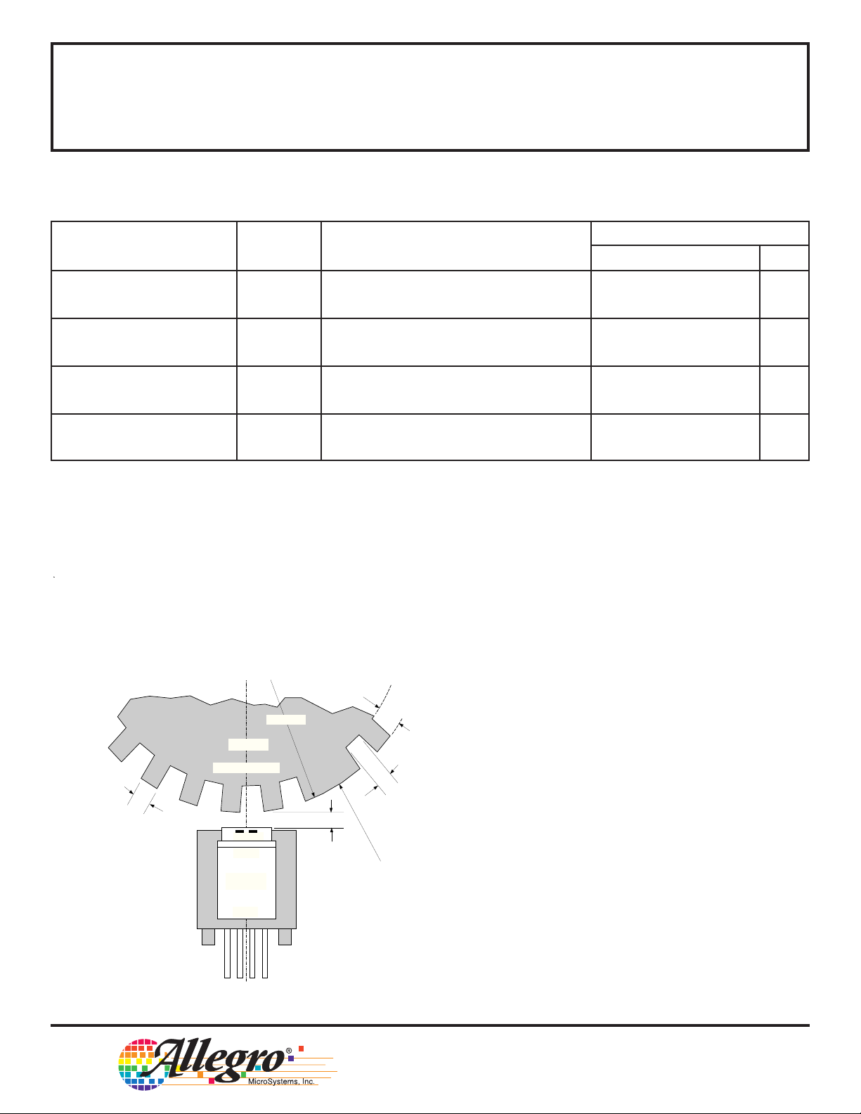
Air Gap Range AG Operating, 0.4 – 2.5 mm
Target Speed > 20 RPM
Calibration Cycle n
cal
Output edges before which 1 1 1 Edge
calibration is completed*
Calibration Mode n
dis
Output falling edges for startup 64 64 64 Edges
Disable calibration to be complete
Timing Accuracy t
θ
Target Speed = 1000 RPM, – ±0.5 ±0.75 °
0.4 mm ≤ AG ≤ 2 mm
* Non-uniform magnetic profiles may require additional output pulses before calibration is completed.
REFERENCE TARGET
3 mm
t
h = 5 mm
TARGET
F (THICKNESS) ≥ 3 mm
D = 115 mm
o
T = 3 mm
E1 E2
SENSOR
POLE PIECE
SOUTH
PERMANENT
MAGNET
NORTH
1 2 3 4
AIR GAP
SIGNATURE
TOOTH (1)
Dwg. MH-016-2 mm
115 Northeast Cutoff, Box 15036
Worcester, Massachusetts 01615-0036 (508) 853-5000
ATS612JSB
DYNAMIC, SELF-CALIBRATING, PEAK-DETECTING,
DIFFERENTIAL HALL-EFFECT GEAR-TOOTH SENSOR
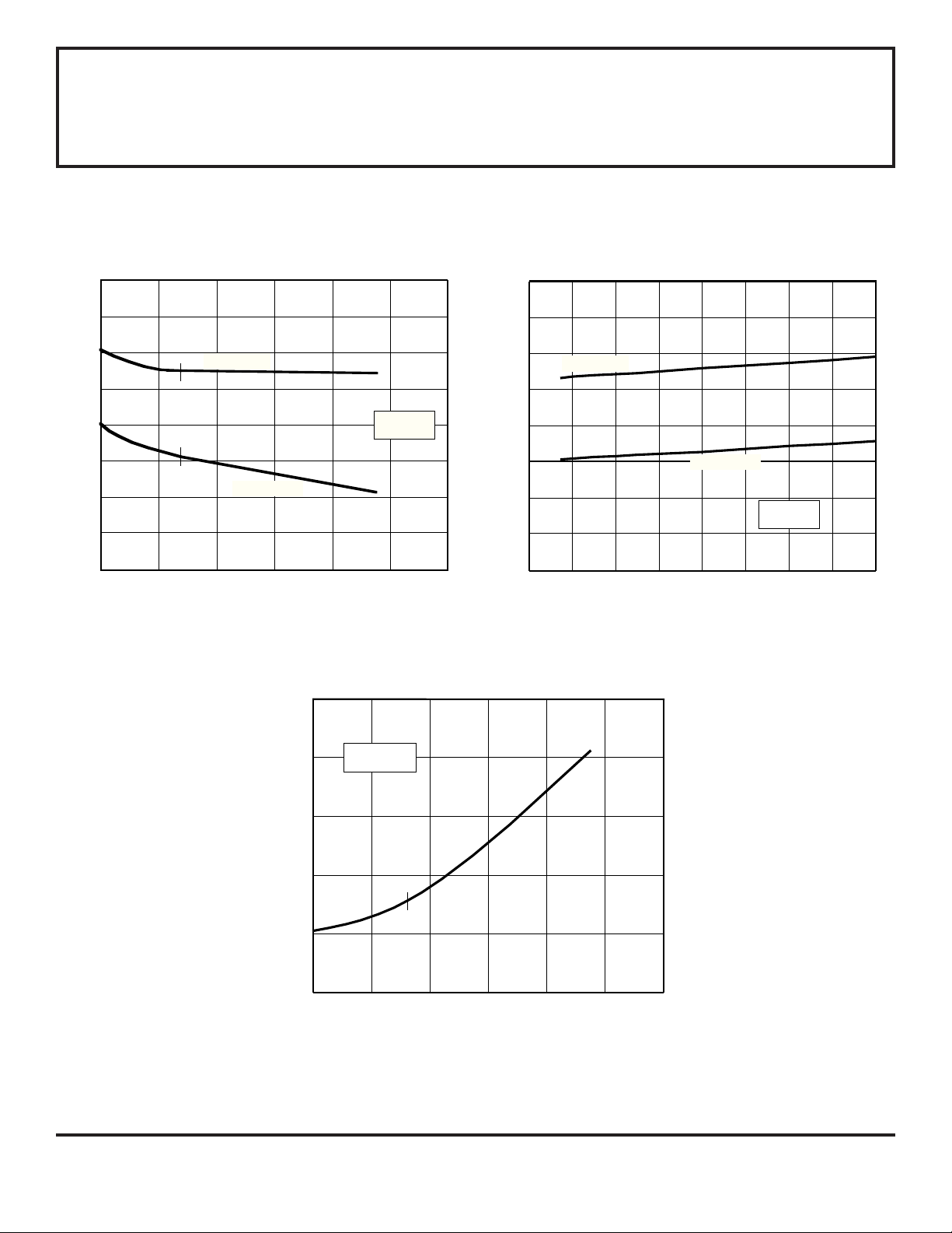
TYPICAL ELECTRICAL CHARACTERISTICS
14
12
11
10
9.0
8.0
7.0
SUPPLY CURRENT IN mA
6.0
4.0
-40
0 40 80 120
AMBIENT TEMPERATURE IN °C
OUTPUT ON
OUTPUT OFF
275
V = 8 V
CC
160
Dwg. GH-014-2
200
13
12
11
10
9.0
8.0
7.0
SUPPLY CURRENT IN mA
6.0
5.0
OUTPUT ON
OUTPUT OFF
T = 25°C
A
2.0 6.0 10 14 18
SUPPLY VOLTAGE IN VOLTS
Dwg. GH-058-1
250
225
200
175
I = 20 mA
OUT
OUTPUT SATURATION VOLTAGE IN mV
150
-40
0 40 80 120
AMBIENT TEMPERATURE IN °C
160
200
Dwg. GH-013-2
 Loading...