

8936
INTERIM DATA SHEET
VOICE COIL MOTOR DRIVER
(Subject to change without notice)
March 16, 1993
8936
Data Sheet
26300.6
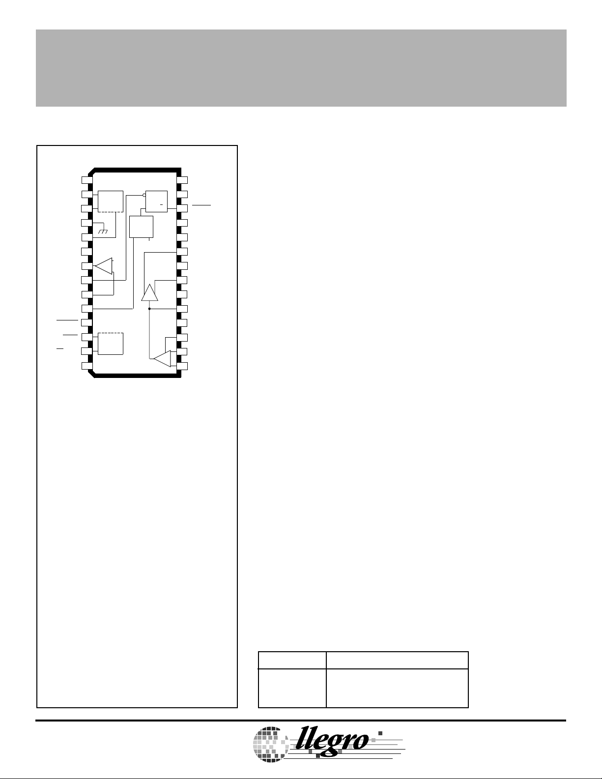
VOICE COIL MOTOR DRIVER
A8936CLW
1
RET REF
V
2
V
BEMF
GROUND
UV
R
OUT P
OUT
EN VEL FLT
IN
VEL
RETRACT
FAULT
MP
RESET
SIGNAL
SUPPLY
FLT
PROTECT
CIRCUIT
3
4
5
SET
6
V
+
PROTECT
CIRCUIT
V
CC
REF
–
7
8
9
N
10
IN
11
12
13
14 15
WINDOW
COMP.
V
REF
R
Q
S
ABSOLUTE MAXIMUM RATINGS
Supply Voltages, VCC and VDD........... 6.0 V
Output Current, I
(continuous) ........................... ±500 mA
Analog Input Voltage Range,
V
................................... -0.3 V to V
IN
Logic Input Voltage Range,
V
............................... -0.3 V to +6.0 V
IN
Package Power Dissipation,
P
........................................ See Graph
D
(peak) .......... ±600 mA
OUT
RET SET
28
27
V
SENS
VEL FLT
26
V
25
SENS FB
24
SGND
N
OUT
23
P
LOAD
22
V
DD
SUPPLY
21
OUT
N
SGND
20
P
ACT
19
FB
18
PWR OFF
H GAIN
17
16
REFERENCE
+
–
ACT
Dwg. PP-046A
CC
Providing control and drive of the voice coil motor used for head
positioning in 5 V disk drive applications, the A8936C— is a full-bridge
driver which can be configured so that its output current is a direct
function of an externally applied control voltage or current. This linear
current control function is supplemented by additional circuitry to
protect the heads and the data disk during system failure or normal
system shutdown. An under- or over-velocity sense disables the
system in a controlled sequence if a fault condition occurs.
The two ±500 mA MOS driver outputs provide very low saturation
voltage and minimal power dissipation. Additional headroom is
achieved by the sense-FET structure eliminating the need for an
external current-sense resistor. Thermal protection and under-voltage
lockout disables the system in a controlled sequence if a fault condition occurs.
FEATURES
■ Over-Velocity Fault Function
■ Lossless Current Sensing
■ Zero Deadband
■ High Transconductance Bandwidth
■ User-Adjustable Transconductance Gain
■ Digital Transconductance Gain Switch (4:1 Ratio)
■ 5 Volt Monitor with Selectable UV Trip Point
■ Retract Circuitry Functional to 0 Volts
■ Chip Enable/Sleep Mode Function
■ 1 V at 500 mA Output Saturation Voltage
■ Internal Thermal Shutdown Circuitry
Operating Temperature Range,
T
.....................................0°C to +70°C
A
Junction Temperature, T
.............. +150°C
J
†
Storage Temperature Range,
T
................................-55°C to +150°C
S
DISCONTINUED PRODUCT
† Fault conditions that produce excessive
junction temperature will activate device thermal
shutdown circuitry. These conditions can be
tolerated, but should be avoided.
Output current rating may be restricted to a value
— FOR REFERENCE ONLY
determined by system concerns and factors.
These include: system duty cycle and timing,
ambient temperature, and use of any heatsinking
and/or forced cooling. For reliable operation the
specified maximum junction temperature should
not be exceeded.
Always order by complete part number:
Part Number Package
A8936CJT 64-Lead Thin Quad Flatpack
A8936CLW 28-Lead SOIC
A
TM
TM
MicroSystems, Inc.
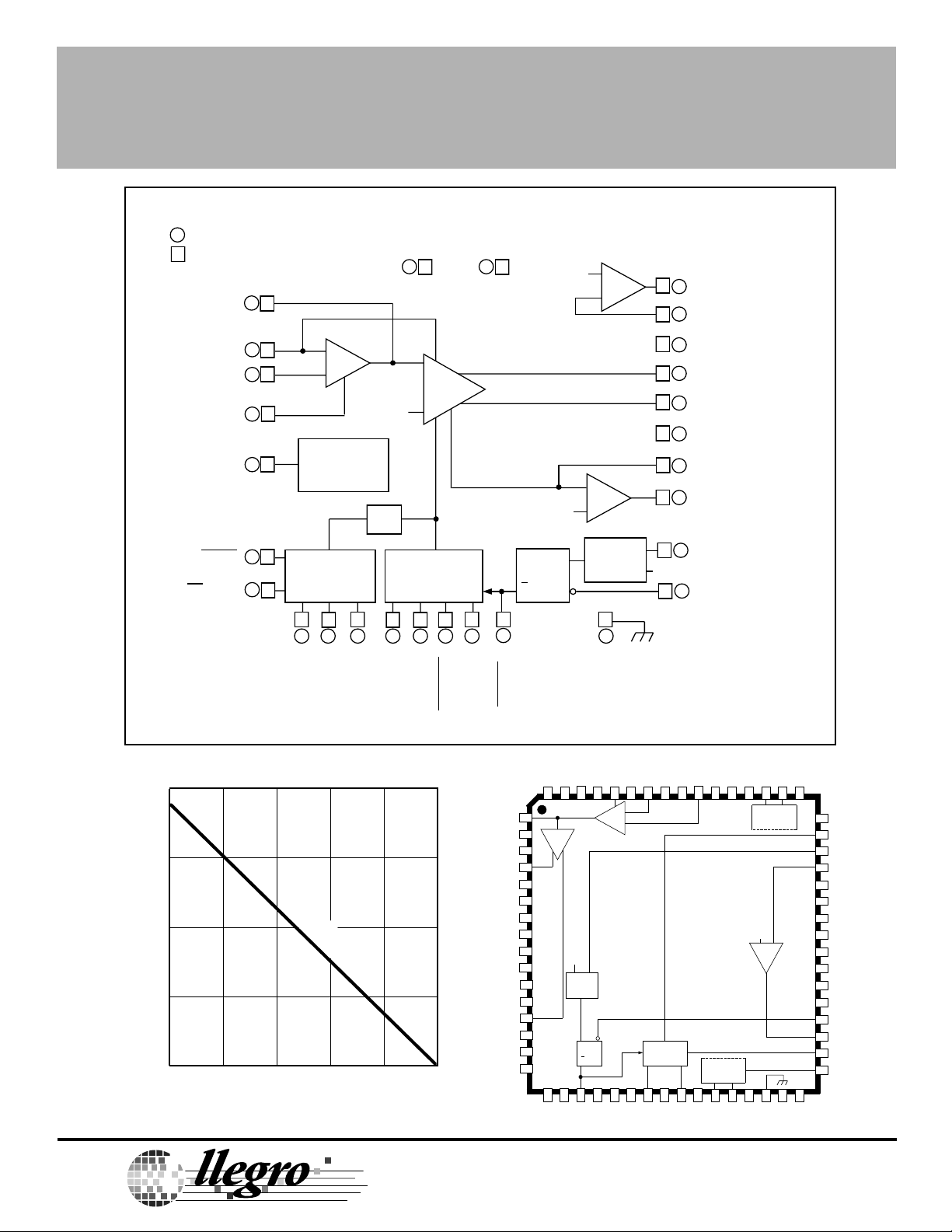
8936
VOICE COIL MOTOR DRIVER
FUNCTIONAL BLOCK DIAGRAM
= 'LW' WIDE-BODY SOIC
= 'JT' THIN QUAD FLATPACK
19
FB
1
15
55
16
58
60
17
18
62
12
50
13
51
ACT
ACT
REFERENCE
H GAIN
PWR OFF
FAULT
MP
RESET
SIGNAL
SUPPLY
14 22
V
CC
I
SENSE +
ERROR
AMP
–
2 V
+
–
+
POWER
CONTROL
LOGIC
TSD
PROTECTION
CIRCUITRY
33
28 27 23 25 47 34
53 2 281 611 4
SET
BEMF
UV
V
V
FLT
RETRACT
CONTROL
RET REF
RET SET
POWER
AMP
I
SENSE –
RETRACT
LOAD
SUPPLY
853
V
DD
19
26
OUT P
R
V
REF
CURRENT-SENSE
AMP
V
REF
S
Q
R
Q
VEL FLT
+
–
–
+
WINDOW
COMP.
30
GROUND
35
45
2
13
4
15
16
21
46
V
REF
36
7
OUT
9
IN
20
SGND
23
OUT
21
OUT
24
SGND
25
V
27
V
10
VEL
8
EN VEL FLT
Dwg. FP-030A
N
P
P
N
N
SENS FB
SENS
IN
2.0
1.5
FREE AIR,
R = 66°C/W
θJA
1.0
0.5
0
25
ALLOWABLE PACKAGE POWER DISSIPATION IN WATTS
A
50 75 100 125 150
AMBIENT TEMPERATURE IN °C
Dwg. GP-034
TM
TM
MicroSystems, Inc.
115 Northeast Cutoff, Box 15036
115 Northeast Cutoff, Box 15036
Worcester, Massachusetts 01615-0036 (508) 853-5000
Worcester, Massachusetts 01615-0036 (508) 853-5000
Copyright © 1992, 1993, Allegro MicroSystems, Inc.
A8936CJT
V
PROTECT.
CIRCUIT
CC
PROTECT.
CIRCUIT
V
REF
+ —
Dwg. PP-052-1
+
—
V
DD
V
REF
WINDOW
COMP.
S R
Q
RETRACT
CONTROL

8936
VOICE COIL MOTOR DRIVER
ELECTRICAL CHARACTERISTICS at T
= +25°C, VCC = VDD = 5.0 V, V
A
= VIN= 2.0 V,
REF
Load = 150 µH/3.5 Ω (unless otherwise noted).
Limits
Characteristic Symbol Test Conditions Min. Typ. Max. Units
Error Amplifier
Input Offset Voltage V
Current Gain A
Current Gain Linearity E
Reference Voltage Range V
IO
iH
A
iL
L(adj)
REF
Current-Sense Amplifier
Voltage Gain A
Input Offset Voltage V
VD
iO
Output Drivers
Output Saturation Voltage V
DS(SAT)
(Source + Sink)
Retract Output Saturation Voltage V
Output Current I
DS(SAT)
O
Full Power Bandwidth BW -3 dB 1.0 —— kHz
Window Comparator
Lower Trip Point VEL
Upper Trip Point VEL
IN
IN
Uncommitted Op Amp
Voltage Gain A
VS
Unity Gain Bandwidth BW — 1.0 — MHz
Max. Load Capacitance C
LOAD
Slew Rate SR — 4.2 — V/µs
Output Voltage V
Max. Output Current I
Input Offset Voltage V
O
O
IO
I
= 0 mA ——50 mV
LOAD
H GAIN ≥ 3.5 V 7200 8000 8800 —
H GAIN ≤ 0.7 V 1800 2000 2200 —
I
= 5 mA to 500 mA, Ai = A
OUT
= 5 mA to 500 mA, Ai = A
I
OUT
iL
iH
——±10 %
——±10 %
1.5 — 2.5 V
Rs = R
gm
I
= 0 mA, Ai = A
LOAD
I
= 100 mA — 0.25 — V
LOAD
I
= 500 mA — 1.5 — V
LOAD
I
≤ 150 mA ——1.0 V
OUT
iL
— 1.0 ——
——±25 mV
Pulse Test, ±600 mA Limited ——±500 mA
1.12 1.25 1.38 V
2.47 2.75 3.03 V
— 91 — dB
40 —— pF
VIO = 100 mV 2.5 — 3.5 V
— ±250 — µA
——±10 mV
Negative current is defined as coming out of (sourcing) the specified device terminal.
Typical Data is for design information only.
Continued next page …
 Loading...