


查询A8450供应商查询A8450供应商
Package LB 24-pin SOIC
VBB
1
CP2
2
CP1
VCP
VREG11
GND
GND
ENB
CPOR
CLADJ
VADJBD
FB
Charge
3
4
5
6
7
8
9
10
1.2Vto
3.3 V
11
Lin Reg
12
Control
Approximate Scale 1:1
Converter
Pump
Buck
Soft
Start
Dig/Anlg
Lin Reg
5 V Reg
Control
5V
Track
3.3 V
Lin Reg
Control
A8450
Automotive Multioutput Voltage Regulator
The A8450 is a multioutput power supply intended for automotive
applications. The A8450 operates from a wide input supply range and
is designed to satisfy the requirements of high ambient temperature
environments.
Four regulated voltage outputs provide multiple options. The 3.3 V
regulator and the 1.2 to 3.3 V adjustable regulator can be used to power
24
23
22
21
20
19
18
17
16
15
14
13
LX
ENBAT
V33
V33BD
CL33
GND
GND
VREG
V5D
NFAULT
NPOR
V5A
microcontroller or DSP cores, or for I/O, sensing, and A-to-D conversion. Two 5 V outputs, one digital and the other analog, feature output
tracking within 0.5% of each other over the operating temperature
range. In addition, the analog regulator is protected against short-tobattery conditions. All four regulators feature foldback current limit
protection.
The device can be enabled or disabled using two input pins. The
high voltage input, on the ENBAT pin, allows enable/disable using an
engine ignition or battery switch signal. The logic-level input, on the
ENB pin, allows enable/disable by microcontroller or DSP signals.
When disabled, the A8450 draws less than 10 µA of current. A POR
(power-on-reset) block monitors the supply voltages and provides a
reset signal, with an adjustable delay, for microcontroller or DSP resets.
A separate fault pin signals TSD (thermal shutdown), 5 V analog shortto-supply, and 5 V analog or digital undervoltage.
The A8450 is supplied in a 24-pin SOIC package (part number
suffix LB) with fused power ground pins for enhanced thermal performance. This provides an R
of 35°C/W on a 4-layer board (see chart
θJA
on p. 4).
AB SO LUTE MAX I MUM RAT INGS
Load Supply Voltage, V
Analog Output, Pin V5A........................–1 V to 45 V
Logic Input Signal
Pin ENBAT .................................–0.3 V to 45 V
Pin ENB .....................................–0.3 V to 6.5 V
Pin LX.................................................... –2 V to V
Operating Temperature Range
Ambient Temperature, T
Junction Temperature, T
Storage Temperature, TS.................... –55°C to 150°C
A8450KLB-DS, Rev. 1
..................................45 V
BB
............ –40°C to 135°C
A
.....................150°C
J(MAX)
FEATURES
6 V to 45 V input range
dc-to-dc buck converter with 5.7 V output
Overcurrent protection with foldback, and undervoltage lockout (UVLO)
Dual 5 V outputs
– Digital 5 V ±2%, 200 mA
– Analog 5 V, 200 mA
– Short-to-supply protection on analog regulator
– Analog to digital regulator output tracking < 0.5%, throughout
operating temperature range
3.3 V linear regulator, with foldback current limit
Adjustable 1.2 V to 3.3 V linear regulator, adjustable foldback current limit
BB
Ignition switch enable; Sleep mode
100% duty cycle operation for low input voltages
Power OK output
–40°C to 135°C ambient operating temperature range
Use the following complete part number when ordering:
Part Number Package Description
A8450KLB 24-pin, SOIC Webbed Leadframe
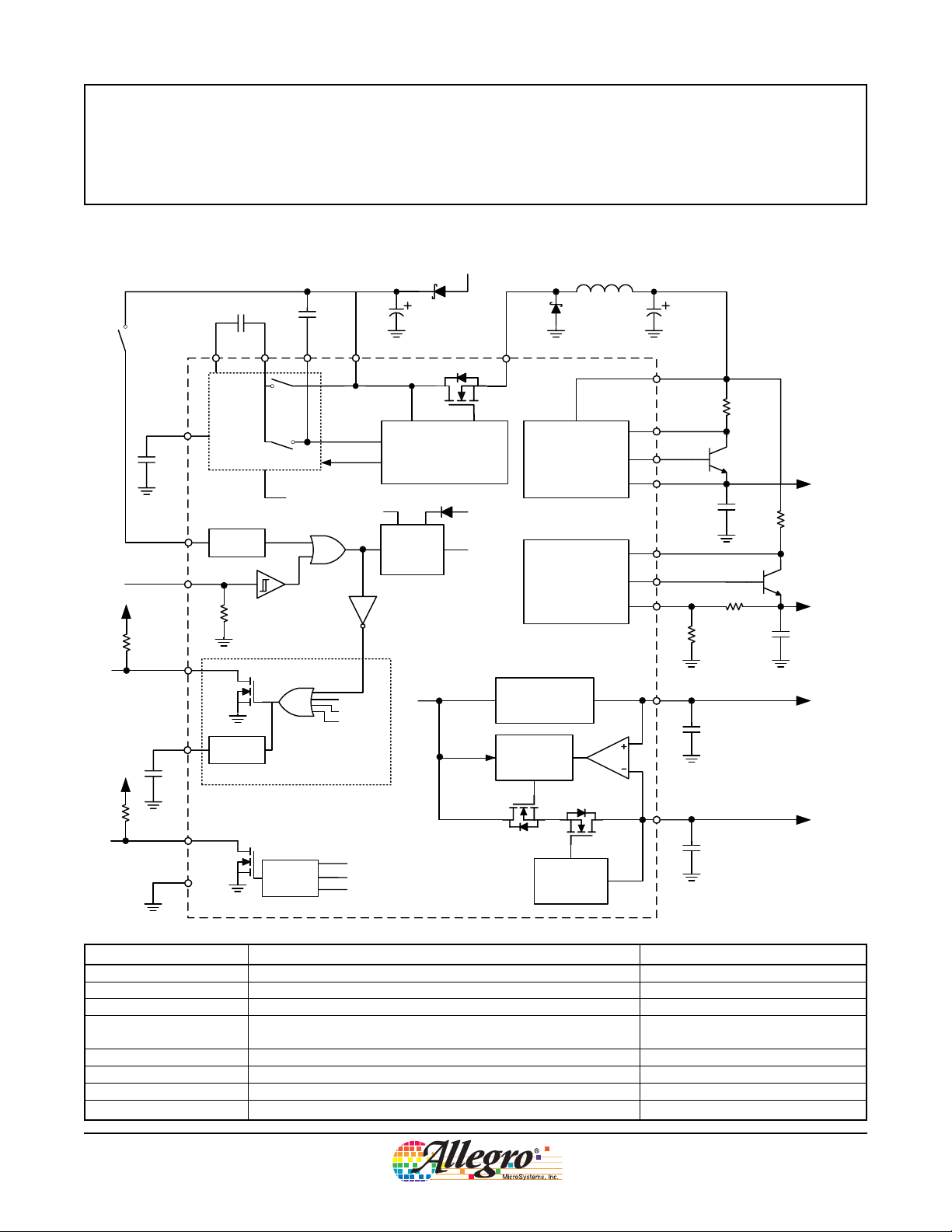
Automotive Multioutput Voltage Regulator
Functional Block Diagram
VIN
D2
A8450
L1
High
Voltage
Switch
VREG11
ENBAT
C10
ENB
NPOR
CPOR
C9
Charge Pump
High V
Protection
Adjustable
Delay
POR Block
C8
CP2CP1 VCP
CPOK
C7
Soft Start
V
UVLOREG
V
UVLOADJ
V
UVLO33
VBB
VBB
Reference
CIN
Buck Converter with
Switching Regulator
Internal
VREG
Current
Limiting
VREG
V
REF
LX
3.3 V Linear
Regulator Control
1.2 V to 3.3 V
Adjustable Linear
Regulator Control
5 V Digital Linear
Regulator
5V Analog
Linear Regulator
and V5D to V5A
Tracking Control
D1
COUT
VREG
CL33
V33BD
V33
CLADJ
VADJBD
FB
V5D
R3
Q1
C3
R1
R2
C1
R4
Q2
VADJ
C4
V5A
NFAULT
GND
Fault
TSD Warning
V5A Short to Supply
UVLO V5D, V5A
Short-to-Supply
Protection
C2
ID Characteristics Representative Device
C1, C2, C3, C4 1 µF, 25 V ceramic X7R
COUT 100 µF, 35 V low-ESR electrolytic UHC1V101M, Nichicon
CIN 47 µF, 63 V electrolytic
C7, C8
0.1 µF, 50 V ceramic X7R (for 14 V applications), or
0.1 µF, 100 V ceramic X7R (for 42 V applications)
C10 0.22 µF, 10 V X7R
D1, D2 1 A, 40 V Schottky (for 14 V applications) EKO4, Sanken
L1 100 µH, 1.2 A D03316HT, Coilcraft
Q1, Q2 pass transistors npn transistor, h
A8450KLB-DS, Rev. 1
> 50 MPSW06
FE
Allegro MicroSystems, Inc.
115 Northeast Cutoff, Box 15036
Worcester, Massachusetts 01615-0036 (508) 853-5000
www.allegromicro.com
2
A8450
Automotive Multioutput Voltage Regulator
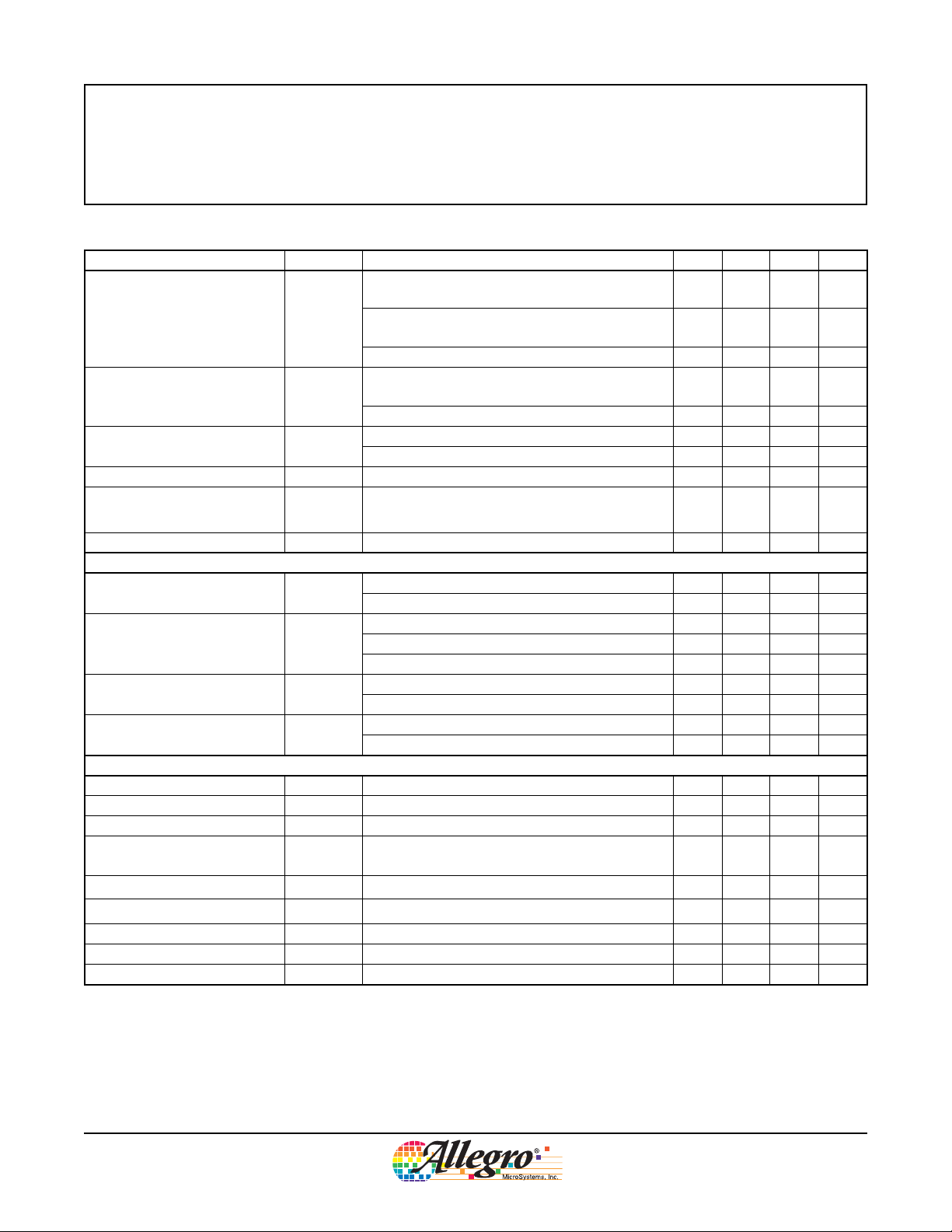
ELECTRICAL CHARACTERISTICS at T
Characteristics Symbol Test Conditions Min. Typ. Max. Units
Supply Quiescent Current I
Regulated Output Voltage V
Buck Switch On-Resistance R
Buck Switch Current Limit I
dc-to-dc Fixed Off-Time t
Soft Start Time t
Logic Inputs
ENBAT Logic Input Voltage V
ENBAT Input Current I
ENB Logic Input Voltage V
ENB Input Current I
Linear Regulator Outputs
*
V5D Output Voltage V
V5A Output Voltage V
V33 Output Voltage V
V5A to V5D Tracking V
V5D Current Limit I
V5A Current Limit I
Base Drive Output Current I
Feedback Voltage V
Feedback Input Bias Current I
Continued on next page
BB
REG
DSON
DSLIM
OFF
SS
ENBAT
ENBAT
ENB
ENB
OUTV5D
OUTV5A
OUTV33
TRACK
OUTV5DLIM
OUTV5ALIM
BD
FB
FB
= –40ºC to 135°C, V
A
Enabled mode: V
I
= 0 mA: V
OUT
BB
Enabled mode: V
I
= 0 mA; VBB = 6 V
OUT
Disabled mode: V
I
= 550 mA = I
LOAD
+ I
LOADVADJ
; VBB > 6.5 V
BB
ENBAT
= 14 V
ENBAT
ENBAT
LOADV5D
or V
or V
= 6 to 45 V, V
= HIGH,
ENB
= HIGH,
ENB
and V
= LOW – – 10 µA
ENB
+ I
LOADV5A
= 5 V, unless otherwise noted
ENB
– 6 10 mA
–1015mA
+ I
LOADV33
5.50 – 5.80 V
Dropout: 6 V ≤ VBB < 6.5 V 5.00 – 5.80 V
TJ = 25°C – 415 500 mΩ
TJ = 135°C – 650 750 mΩ
1.0 1.2 1.8 A
VBB = 14 V – 4.75 – µs
VBB = 14 V 5 10 15 ms
HIGH input level 2.7 – 45 V
LOW input level –0.3 – 0.8 V
HIGH input level, V
HIGH input level, V
LOW input level, V
= 45 V – – 300 µA
ENBAT
= 14 V – – 70 µA
ENBAT
= 0.8 V –1 – 10 µA
ENBAT
HIGH input level 2.7 – 6.5 V
LOW input level –0.3 – 0.8 V
HIGH input level, V
LOW input level, V
1 mA ≤ I
1 mA ≤ I
LOADV5D
LOADV5A
≥ 2.7 V – – 50 µA
ENB
≤ 0.8 V –1 – 10 µA
ENB
≤ 200 mA 4.9 5.0 5.1 V
≤ 200 mA 4.9 5.0 5.1 V
3.234 3.300 3.366 V
50 mA ≤ I
V
> 6.5 V
BB
LOADV5A
, I
LOADV5D
≤ 200mA;
–25 – 25 mV
200 300 – mA
200 300 – mA
1 V ≤ V
OUTVADJ
, V
≤ 4 V 5.0 10.0 16.0 mA
OUTV33
1.16 1.20 1.24 V
–400 –100 100 nA
A8450KLB-DS, Rev. 1
Allegro MicroSystems, Inc.
115 Northeast Cutoff, Box 15036
Worcester, Massachusetts 01615-0036 (508) 853-5000
www.allegromicro.com
3

A8450
Automotive Multioutput Voltage Regulator
ELECTRICAL CHARACTERISTICS (continued) at T
otherwise noted
Characteristics Symbol Test Conditions Min. Typ. Max. Units
Protection
NFAULT, NPOR Output Voltage V
NFAULT, NPOR Leakage Current I
POR Delay t
V33 Undervoltage Threshold V
V33 Hysteresis V
V5A, V5D Undervoltage Threshold V
V5A, V5D Hysteresis V
VADJ Undervoltage Threshold V
VADJ Hysteresis V
VADJ, V33 Overcurrent Threshold V
VREG Undervoltage Threshold V
Thermal Warning Threshold T
Thermal Shutdown Threshold T
Thermal Shutdown Hysteresis T
*
Linear regulator output specifications are only valid when V
ERRON
ERROFF
POR
UVLOV33
HYSV33
UVLOV5
HYSV5
UVLOVADJ
HYSVADJ
OC
UVLOVREG
JTW
JTSD
HYSTSD
Fault asserted;
I
NFAULT
V
NFAULT
C9 = 0.47 µF 65 100 135 ms
V33 rising 2.80 2.95 3.10 V
V
falling 2.75 2.90 3.05 V
33
–80–mV
V
REG
V
REG
VFB rising 1.02 1.07 1.12 V
V
FB
At FB pin – 70 – mV
TJ rising – 160 – °C
TJ rising – 175 – °C
Recovery period = T
is in regulation (VBB ≥ 6.5).
REG
= –40ºC to 135°C, V
A
, I
= 1 mA
NPOR
, V
= 5 V – – 1 µA
NPOR
= 6 to 45 V, V
BB
= 5 V, unless
ENB
– – 400 mV
rising 4.36 4.50 4.75 V
falling 4.24 4.38 4.63 V
– 125 – mV
falling 0.97 1.02 1.07 V
175 200 225 mV
4.94 5.15 5.36 V
JTSD
– T
JTW
–15–°C
A8450KLB-DS, Rev. 1
Power Dissipation Versus Ambient Temperature
4.5
4.0
3.5
(W)
D
3.0
2.5
2.0
1.5
4-Layer PCB*
(R
=35ºC/W)
θJA
Power Dissipation, P
1.0
0.5
0.0
20 40 60 80 100 120 140 160
Ambient Temperature (°C)
*In still air; mounted on PCB based on JEDEC high-conductance standard PCB
(JESD51-7; High Effective Thermal Conductivity Test Board for Leaded Surface Mount
Packages); data on other PCB types is provided on the Allegro Web site.
Allegro MicroSystems, Inc.
115 Northeast Cutoff, Box 15036
Worcester, Massachusetts 01615-0036 (508) 853-5000
www.allegromicro.com
4
V
REG
V
OUTV33
V
OUTVADJ
V
OUTVADJ
V
ENBAT
V
ENBAT
V
ENB
V
ENB
V
NPOR
V
NPOR
V
NPOR
V
BB
V
REG
V
OUTV33
V
OUTV5A/V5D
VREG Monitor
V
CP
V
REG
V
OUTV33
V
OUTVADJ
V
UVLOV33
t
POR
t
POR
t
POR
t
POR
V
HYSV33
V
UVLOV33
VBB>6V
V
REG
= 1.8 V
V
UVLOVREG
V
UVLOVADJ
V
HYSVADJ
AB
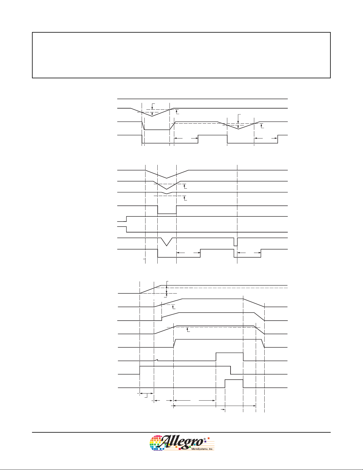
POR event initiates
+7 V
Slope of V
OUTV33
and V
OUTVADJ
from A to B determined by I
LOAD
and output capacitor (C3, C4).
ENBAT signals power-on
Charge pump ramping
Charge pump OK flag set
V
UVLOV33
exceeded; VADJ enabled
V
UVLO(33)
ENB signals power-off
V33 can sustain regulation with normal load by bulk capacitor (COUT) on V
REG
.
Slope of V
REG
(which controls V
OUTV5A/V5D
,V
OUTV33
, and V
OUTVADJ
) from A to B determined by I
LOAD
and COUT.
A
B
t
POR
t
SS
Figure 1a. NPOR fault due to undervoltage lockout on the V33 or FB pins
A8450
Automotive Multioutput Voltage Regulator
Timing Diagrams
Figure 1b. Power-off using V
Figure 1c. Power-on using ENBAT, followed by power-off using ENB
A8450KLB-DS, Rev. 1
BB
Allegro MicroSystems, Inc.
115 Northeast Cutoff, Box 15036
Worcester, Massachusetts 01615-0036 (508) 853-5000
www.allegromicro.com
5

VIN = 12 V; I
I
LOAD
Automotive Multioutput Voltage Regulator
Load Transients Diagrams
= 100 mA; TA = 25°C; ac-coupled; C1, C2, C3 and C4 = 1 µF
LOAD
3.3 V Regulator
90%
A8450
= 5 to 100 mA
LOAD
I
(50 mV / Div.)
OUT
V
10%
t
RISE
t (0.2 µs/Div.)
V5D Regulator
t (50 µs/Div.)
V5A Regulator
(50 mV / Div.)
OUT
V
t (50 µs/Div.)
Adjustable Regulator, at 1.8 V*
(50 mV / Div.)
OUT
V
t (50 µs/Div.)
*For the adjustable regulator, the transient load response
is improved as the voltage is reduced. This is due to the
ability of the regulator to provide more base drive (V
because of more available voltage. When the adjustable
ADJBD
regulator approaches 3.3 V, its transient load response is
equivalent to the response of the V33 regulator.
)
(50 mV / Div.)
OUT
V
A8450KLB-DS, Rev. 1
t (50 µs/Div.)
For all regulators, load transients can be improved by
increasing the output capacitance (C1, C2, C3, and C4).
In order to keep ESR down it is best to use ceramic type
capacitors. However, large values in ceramic type capacitors
are either not available or very expensive. If larger values are
needed, above 22 µF, electrolytic capacitors with low ESR
ratings can be used. Performance can be improved further
by adding a 1 µF ceramic in parallel with the electrolytic.
Allegro MicroSystems, Inc.
115 Northeast Cutoff, Box 15036
Worcester, Massachusetts 01615-0036 (508) 853-5000
www.allegromicro.com
6

Automotive Multioutput Voltage Regulator
VBB
LX
D1
L1
100 µH
COUT
100 µF
VREG
Switching
Regulator
Control
Clock
Counter
Soft Start
Ramp
Generation
Error
Bandgap
1.22 V
Clamp
t
OFF
VCP
Compensation
1.2 A Limit
I
PEAK
I
DEMAND
ENB
Buck Converter
Buck Switch
5.5
5 7 9 11 13 15
5.0
4.5
4.0
3.5
3.0
2.5
2.0
1.5
1.0
0.5
0.0
t
OFF
by V
BB
VBB(V)
t
OFF
(µs)
4.75 µs
12 V
2.05 µs
11 V
0.58 µs
6.02 V
Functional Description
Buck Converter with Switching Regulator. A current-mode, variable frequency buck dc-to-dc converter and
switching regulator are integrated in the A8450, as shown in
figure 2. This feature allows the device to efficiently handle
power over a wide range of input supply levels. The dc-to-dc
converter outputs 5.7 V typical, and has an overcurrent limit
of 1.2 A typical.
The converter employs a soft-start feature. This ramps the
converter output voltage and limits the maximum demand on
by controlling the inrush current required at power-on
V
REG
to charge the external capacitor, COUT, and any dc load.
An internal charge pump provides gate drive for the
N-channel MOSFET buck switch. A 100% duty cycle is
implemented when using low VBB input voltages.
A8450
At VBB lower than 12 V, off-time, t
in figure 3. This reduction keeps the switching frequency,
f
, within a reasonable range and lowers the ripple cur-
PWM
rent. Lowering the ripple current at low VBB levels prevents
degradation of linear regulator headroom due to V
voltage.
5 V Linear Regulators. Two 5 V medium-power linear regulators are provided. These low-dropout regulators feature foldback
current limiting for short-to-supply protection. When a direct
Figure 2. Buck converter with switching regulator
A8450KLB-DS, Rev. 1
, is reduced, as shown
OFF
Figure 3. When VBB falls below 12 V, t
ripple
REG
Allegro MicroSystems, Inc.
115 Northeast Cutoff, Box 15036
Worcester, Massachusetts 01615-0036 (508) 853-5000
www.allegromicro.com
decreases
OFF
7

A8450
Automotive Multioutput Voltage Regulator
short is applied to the regulator output, either V5A or V5D,
the current folds back to 0 V at 50 mA, as shown in figure 4a.
The voltage recovers to its regulated output when the short is
removed.
The V5A and V5D regulators track each other during poweron, and when the device is enabled and ramped up out of
disabled mode, the regulators will start to track when V
REG
reaches approximately 1.8 V. These regulators are guaranteed
to track to within 0.5% of each other under normal operating
conditions.
3.3 V and Adjustable Linear Regulators. Two additional
linear regulators, one that outputs at 3.3 V, and another that has
a 1.2 V to 3.3 V adjustable output, can be implemented using
external npn pass transistors. The output voltage of the adjustable regulator, V
OUTVADJ
(V), is set by the values of the output
resistors, R1 and R2 (Ω). It can be calculated as
V
OUTVADJ
= VFB (1+R1 ⁄ R2)
where VFB (V) is the voltage on the feedback pin, FB.
Additional pins, CL33 and CLADJ, are provided for setting
current limits. These are used to protect the external pass transis-
tors from a short-to-ground condition. The current limit setting,
I
(mA), is calculated using the formula
CL
ICL = VOC ⁄ R
RCL
where RCL (Ω) is the current-limiting resistor corresponding to
that regulator (R3 for the 3.3 V regulator, and R4 for the adjustable regulator). When ICL is exceeded, the maximum load current
through that regulator is folded back to 40% of ICL ±10%, as
shown in figure 4b. If current limiting is not needed, the CL33
and CLADJ pins should be shorted to the VREG pin.
Disabled Mode. When the two input signal pins, ENBAT
and ENB, are pulled low, the A8450 enters disabled mode.
This is a sleep mode, in which all internal circuitry is disabled in order to draw a minimal current from VBB. When
either of these pins is pulled high, the device is enabled.
When emerging from disabled mode, the buck converter
switching regulator does not operate until the charge pump
has stabilized (≈ 300 µs).
Enabled Mode. When one or both of the signal input
pins, ENBAT and ENB, are in the high state, the A8450 is
enabled.
6
5
4
(V)
3
OUT
V
2
1
0
0 50 100 150
Figure 4a. Linear foldback to 50 mA. Foldback occurs at the
typical current limit for the 5 V regulator.
5V Regulators Overcurrent Foldback
I
OUT
I
and I
OUTV5DLIM
200 250 300
(mA)
OUTV5ALIM
A8450KLB-DS, Rev. 1
1600
3.3 V and Adjustable Regulators Overcurrent Foldback
6
5
4
(V)
3
OUT
V
2
1
0
0
Figure 4b. Linear foldback to a percentage of ICL . Foldback
occurs at the current limit setting for the regulator.
V
V
OUTVADJ(min)
0.4 ICL±10%
and V
OUTV33
OUTVADJ(max)
I
(mA)
OUT
Allegro MicroSystems, Inc.
115 Northeast Cutoff, Box 15036
Worcester, Massachusetts 01615-0036 (508) 853-5000
www.allegromicro.com
I
CL
1600
8

A8450
Automotive Multioutput Voltage Regulator
ENBAT is an edge-triggered enable (logic 1 ≥ 2.7 V), which
is used to enable the A8450 in response to a high-voltage
signal, such as from an automobile ignition or battery switch.
In this capacity, ENBAT is used only as a momentary switch
to wake up the device. If there is no need for a high-voltage
signal, ENBAT can be pulled low continuously.
ENB is used to initiate the reset of the device. If ENBAT is
pulled low, ENB acts as a single reset control.
Diagnostics. An open drain output, through the NFAULT
pin, is pulled low to signal to a DSP or microcontroller any of
the following fault conditions:
• V5A, the 5 V analog regulator output, is shorted to supply
• Either or both of the V5A and the V5D regulator outputs
are below their UVLO threshold, V
UVLOV5
• Device junction temperature, TJ, exceeds the Thermal
Warning threshold, T
JTW
Charge Pump. The charge pump generates a voltage above
VBB in order to provide adequate gate drive for the N-channel
buck switch. A 0.1 µF ceramic monolithic capacitor, C7, should
be connected between the VCP pin and the VBB pin, to act as
a reservoir to run the buck converter switching regulator.
V
is internally monitored to ensure that the charge pump is
CP
disabled in the case of a fault condition. In addition, a 0.1 µF
ceramic monolithic capacitor, C8, should be connected between
CP1 and CP2.
Power On Reset Delay. The POR block monitors the sup-
ply voltages and provides a signal that can be used to reset a
DSP or microcontroller. A POR event is triggered by any of
the following conditions:
• Either V33 or VADJ is pulled below its UVLO threshold,
V
UVLOV33
or V
UVLOVADJ
. This occurs if the current limit
on either regulator,
the VREG voltage falls below V
exceeding I
DSLIM
V
, is exceeded. It also occurs if
OC
REGMON
.
, due to current
• Both input signal pins, ENB and ENBAT, are pulled low.
This immediately pulls the NPOR pin low, indicating that
the device is beginning a power-off sequence. In addition,
the buck converter switching regulator is disabled, and
the VREG supply begins to ramp down. The rate at which
V
decays is dependent on the total current draw, I
REG
LOAD
and value of the output capacitors (C1, C2, C3, and C4).
• V
• During any normal power-on, V
drops below its UVLO threshold, V
REG
V
UVLOVADJ
, triggering a POR.
OUTVADJ
UVLOVREG
falls below
.
An open drain output, through the NPOR pin, is provided to
signal a POR event to the DSP or microcontroller. The reset
occurs after an adjustable delay, t
tor, C9, connected to the CPOR pin. The value of t
, set by an external capaci-
POR
POR
(ms) is
calculated using the following formula
= 2.13×10⁵ × C
where C
t
POR
(µF) is the value of the C9 capacitor.
CPOR
CPOR
A POR can be forced without a significant drop in the supply
voltage, V
, by pulsing low both the ENB and the ENBAT
REG
pins. However, pulse duration should be short enough so that
V
does not drop significantly.
REG
Thermal Shutdown. When the device junction temperature,
, is sensed to be at T
T
J
warning temperature, T
(≈15°C higher than the thermal
JTSD
), a fault is indicated at the NFAULT
JTW
pin. At the same time, a thermal shutdown circuit disables the
buck converter, protecting the A8450 from damage.
,
A8450KLB-DS, Rev. 1
Allegro MicroSystems, Inc.
115 Northeast Cutoff, Box 15036
Worcester, Massachusetts 01615-0036 (508) 853-5000
www.allegromicro.com
9

Automotive Multioutput Voltage Regulator
Application Information
A8450
Component Selection
Output Inductor (L1). This inductor must be rated to handle
the total load current, I
. In addition, the value chosen
LOAD
must keep the ripple current to a reasonable level. A typical
selection is a power inductor rated at 100 µH and 1.3 A.
The worse case ripple current, I
RIPPLE(max)
(mA), can be
calculated as
I
RIPPLE(max)
= V
L1OFF
×
t
OFF
⁄ LL1
where LL1 (µH) is the inductance for the selected component,
and V
is the voltage (V) through the inductor when the
L1OFF
A8450 is in the quiescent state
= V
V
L1OFF
REG(max)
where VD1 (V) is the voltage drop on diode D1, I
+ VD1 + (I
LOAD
×
RL1)
LOAD
(mA)
is the total load current, and RL1 is the specified dc resistence
(Ω) for the selected inductor at its rated temperature.
The frequency, f
(Hz), of the switching regulator in the
PWM
buck converter can then be estimated by
f
= 1/(tON + t
PWM
OFF
)
where tON (µs) is calculated as
tON = I
and V
V
L1ON
(V) as
= VBB – (I
L1ON
RIPPLE(max)
LOAD
×
×
R
LL1 ⁄ V
DSON(max)
– (I
LOAD
L1ON
)
×
RL1) – V
REG(max)
Example
Given a typical application with VBB = 14 V, t
and I
= 550 mA. (Note that the value for t
LOAD
= 4.75 µs,
OFF
is con-
OFF
stant for VBB > 12 V, as shown in figure 3.)
Given also a 100 µH power inductor rated at 400 mΩ for
125ºC. (Note that temperature ratings for inductors may
include self-heating effects. If a 125ºC rating includes a selfheating temperature rise of 20ºC at maximum current, then
the actual ambient temperature, T
, cannot exceed 105ºC.)
A
V
I
V
= 5.8 + 0.8 + (0.550
L1OFF
RIPPLE(max)
L1ON
= 6.821
= 14 – (0.550
0.400) = 6.821 V
×
4.75 ⁄ 100 = 0.324 A
×
0.750) – (0.550
×
×
0.400)
– 5.8 = 7.56 V
tON = 0.324
f
= 1/(4.3 + 4.75) = 111 kHz
PWM
100 ⁄ 7.56 = 4.3 µs
×
In the case of a shorted output, the buck converter could
reach its internal current limit, I
ensure safe operation, the I
SAT
rating for the selected induc-
, of 1.2 A typical. To
DSLIM
tor should be greater than 1.4 A. However, if the external
current limit resistors, R3 and R4, selected for the 3.3 V and
adjustable (1.2 V to 3.3 V) regulators, are rated such that the
total inductor current, I
, could never reach that inter-
LOAD
nal current limit, then an inductor can be selected that has
an I
rating closer to the calculated output current of the
SAT
device, I
Higher inductor values can be chosen to lower I
, plus the maximum ripple current, I
LOAD
RIPPLE(max)
. This
RIPPLE
may be an option if it is desired to increase the total maximum current that is drawn from the switching regulator. The
maximum total current available, I
I
LOAD
= I
DSLIM
– (I
(mA), is calculated as
LOAD
RIPPLE(max)
⁄ 2)
Catch Diode (D1). The Schottky catch diode should be
rated to handle 1.2 times the maximum load current, I
LOAD
,
because the duty cycle at low input voltages, VBB, can be
very close to 100%. The voltage rating should be higher than
the maximum input voltage, V
, expected during any
BB(max)
operating condition.
VREG Output Capacitor (COUT). Voltage ripple in the
VREG output is the main consideration when selecting the
VREG output capacitor, COUT. The peak-to-peak output
voltage ripple, V
V
RIPPLE(p-p)
RIPPLE(p-p)
(mV), is calculated as
= I
RIPPLE
×
ESR
COUT
with ESR in ohms. It is recommended that the maximum
level of V
RIPPLE(p-p)
be less than 200 mV.
.
A8450KLB-DS, Rev. 1
Allegro MicroSystems, Inc.
115 Northeast Cutoff, Box 15036
Worcester, Massachusetts 01615-0036 (508) 853-5000
www.allegromicro.com
10

A8450
Automotive Multioutput Voltage Regulator
For electrolytic output capacitors, a low-ESR type is recommended, with a minimum voltage rating of 10 V. However,
because ESR decreases with voltage, the most cost-effective
choice may be a capacitor with a higher voltage rating.
Regulator Output Capacitors (C3 and C4). The output
capacitors used with the 3.3 V regulator (C3) and the 1.2 V
to 3.3 V adjustable regulator (C4), should be 1 µF or greater
X7R (5% tolerance) ceramic or equivalent capacitors, with
a maximum capacitance change of ±15% over a temperature
range of –55ºC to 125ºC.
The ESR of these capacitors does not affect the outputs of
the corresponding regulators. If a greater capacitance is used,
the regulators have improved ripple rejection at frequencies
greater than 100 kHz.
Pass Transistors (Q1 and Q2). The pass transistors
used to implement the 3.3 V regulator and the 1.2 V to 3.3 V
adjustable regulator must ensure the following:
• Stable operation. The cutoff frequency for the control
loops of the regulators is 100 kHz. Transistors must be
selected that have gain bandwidth product, f
(kHz), and
T
beta, hFE (A), ratings such that
fT ⁄ hFE > 100 kHz
• Adequate base drive. It is acceptable to use a lower level
of current gain, hFE, for lower total load currents, I
The lower limit for I
current for the A8450, I
is limited by the minimum base
LOAD
, and the minimum hFE of
BD(min)
LOAD
.
the pass transistor, such that
For a typical application where V
2.5 V, and I
= 190 mA
LOAD
PD = (5.8 – 2.5)
×
= 5.8 V, V
REG
190 = 627 mW
OUT
=
Adjusting Pass Transistor Power Dissipation
Transistors are manufactured in a wide variety of package types, and the thermal dissipation efficiencies of the
packages can vary greatly. In general, increasing thermal
efficiency can also increase cost substantially. Selecting the
package to closely match operating conditions is important to
optimizing application design and cost.
Even when using a thermally-enhanced package, it remains
difficult to provide high current to a load at high ambient
operating temperatures. Depending on the load requirements,
using drop resistors, as shown in figure 5, may be necessary
to protect the pass transistor from overheating.
The output current-limiting resistors, RCL (corresponding
to R3 and R4), will drop between 175 mV and 225 mV at
the highest current output, I
resistance, the voltage dropped, V
VREG
CL33
. Assuming no additional
LOAD
(mV), on each pass
DROP
RCL
I
LOAD
= I
BD(min)
×
h
FE(min)
Note that hFE is dependant on operating temperature.
Lower temperatures decrease hFE, affecting the current
capacity of the transistor.
• Packaged for sufficient power dissipation. In order to
ensure appropriate thermal handling, the design of the application must take into consideration the thermal characteristics of the PCB where the A8450 and pass transistors
are mounted, the ambient temperature, and the power
dissipation characteristics of the transistor packages. In
general, the power dissipation, PD (mW), is estimated by
PD = (V
A8450KLB-DS, Rev. 1
REG
– V
OUT
)
I
LOAD
×
I
A8450
V33BD
V33
Figure 5. Placement of drop resistors for thermal protection; example
shown is for the 3.3 V regulator.
Allegro MicroSystems, Inc.
115 Northeast Cutoff, Box 15036
Worcester, Massachusetts 01615-0036 (508) 853-5000
www.allegromicro.com
V
V
DROP
CE
LOAD
V
OUTV33
11

A8450
Automotive Multioutput Voltage Regulator
transistor is
V
DROP
= V
REG
– V
RCL
– V
OUT
This can be substituted into the power dissipation formula
PD = V
DROP
Given a typical application where V
0.175 V, V
= 3.3 V, and I
OUT
I
×
LOAD
= 5.8 V, V
REG
= 350 mA, then PD is
LOAD
RCL
=
approximately 814 mW.
PD can be used to estimate the minimum required operating
temperature rating for the transistor. The ability of a package
to dissipate heat is approximated by the thermal resistance
from the die (junction) to the ambient environment, R
θJA
(°C/W). This includes the significant effect of dissipation through the package leads and the PCB on which the
transistor is mounted, and the state of the ambient air. The
typical rating for a DPAK package is 32˚C/W. The expected
self-induced temperature rise in the package, ∆TJ (°C), given
PD = 0.814 W, is approximated as
∆TJ = P
R
= 26°C
×
D
θJA
In automotive applications, where under-the-hood ambient
temperatures can exceed 125˚C, the pass transistor would
have to be rated to provide the required beta at ≥ 151°C, plus
a safe operating margin.
Assume that V
REG(max)
= 5.8 V and V
OUT(max)
= 3.3 V.
Assume also that TA = 125°C, and VCE = 1V (as specified for
the MPSW06 npn transistor, beta = 300 at 125˚C).
In order to determine the resistance values for the currentlimiting and drop resistors, V
in terms of I
V
Assume a typical I
LOAD(lim)
RCL
V
RDROP
LOAD
= (I
= (I
= 350 mA. However, under normal
and V
RCL
LOAD(lim)
LOAD(lim)
×
×
can be expressed
DROP
RCL)
R
RDROP
)
operating conditions, the current limit set by RCL would
be higher than the expected normal current, so assume
I
LOAD(lim)
mine V
We can now solve for R
= 0.400 A and RCL = 44 Ω. Substituting to deter-
RCL
V
= 0.400
RCL
V
– V
REG
RCL
– (I
5.8 – 0.176 – (0.4 × R
RDROP
LOAD
×
×
0.44 = 0.176 V
and then V
R
RDROP
DROP
) – V
RDROP
) – 1 ≥ 3.30 V
CE
≥ V
OUT
therefore
R
RDROP
≥ 3.31 Ω
and
For a selected transistor, VCE can change depending on current, temperature, and transistor beta. Typically, transistors
are rated at a minimum beta at a defined VCE. However, VCE
should be calculated with some margin so there is always
enough headroom to drive the device at the desired load.
To provide an operating margin, or if a lower-value RCL is
required, voltage drop resistors, RDROP, can be added to
the circuit, between the RCL and the transistor (figure 5). It
is also important to consider tolerances in resistance values
and V
. The level of V
REG
REG(min)
is 5.6 V, at which level PD
is reduced, but also the voltage available for VCE is reduced.
Calculating maximum and minimum voltage drops is useful
in determining the values of the drop resistors.
The required drop resistor value, R
, can be determined
RDROP
in terms of the voltage drops across each component of the
circuit, as shown in the following formula
V
DROP
≥ V
OUT
where
V
= V
DROP
A8450KLB-DS, Rev. 1
REG
– V
RCL
– V
RDROP
– VCE
V
= 0.4 × 3.31 = 1.3 V
RDROP
Using four 0.25 W resistors valued at 14.7 Ω in parallel will
drop 1.3 volts.
Using the drop resistors as calculated above, the power dissipation in the transistor, P
= I
P
D
LOAD(lim)
(W) is reduced to
D
(V
×
REG
– V
RCL
– V
RDROP
– V
OUT
)
= 0.400× (5.8 – 0.176 – 1.3 – 3.3) = 0.410 W
and
∆TJ = PD
×
R
θJA
= 13°C
The power dissipated in the transistor is significantly
reduced. A transistor in a power package with an R
θJA
of
32˚C/W at 400 mA (a 50 mA margin) undergoes a temperature rise of 13˚C with the drop resistors, as opposed to a
similar transistor at 350 mA rising 26˚C without drop resistors. At high output currents, properly selected drop resistors
can protect the external pass transitor from overheating.
Allegro MicroSystems, Inc.
115 Northeast Cutoff, Box 15036
Worcester, Massachusetts 01615-0036 (508) 853-5000
www.allegromicro.com
12

Automotive Multioutput Voltage Regulator
A8450 Power Dissipation. The A8450 is designed to
operate in applications with high ambient temperatures. The
total power dissipated in the device must be considered in
conjunction with the thermal dissipation capabilities of the
PCB where the A8450 is mounted, as well as the capabilities
of the device package itself.
The ability of a package to dissipate heat is approximated by
the thermal resistance from the die (junction) to the ambient environment, R
effect of dissipation through the package leads and the PCB
on which the package is mounted, and the temperature of the
ambient air. Test results for this 24-lead SOIC are approximately 35 °C/W when mounted on a high-thermally conductive PCB (based on the JEDEC standard PCB, having four
layers with buried copper areas).
The total power that can be applied to the device, P
(W), is affected by the maximum allowable device junction
temperature, T
ture, TA (°C), as shown in the following formula
P
can be estimated based on several parameters, using
D(lim)
the following formula
P
D(lim)
= P
+ P
where
(°C/W). This includes the significant
θJA
J(max)
P
D(lim)
D(Ibias)
(°C), R
= (T
+ P
, and the ambient air tempera-
θJA
– TA) ⁄ R
J(max)
D(V5A)
+ P
D(V5D)
θJA
+ P
D(buckdc)
D(buckac)
D(lim)
+ P
D(BD)
A8450
P
, the relationship can be assumed to be linear through-
D(lim)
out the practical TJ operating range (see test conditions for
R
in the Electrical Characteristics table).
DSON
DC (duty cycle) is a function of VBB and V
calculated precisely as
DC = V
REG(off)
⁄ (V
REG(on)
+ V
A rough estimate for DC is
DC = (V
I
V33BD(max)
is the maximum current drawn on the V33BD
pin. It is dependent on I
+ VLX) ⁄ V
REG
and the hFE of the pass tran-
OUTV33
sistor.
I
ADJBD(max)
pin. It is dependent on I
is the maximum current drawn on the VADJBD
OUTVADJ
and the hFE of the pass
transistor.
Overcurrent Protection
The current supplied by the 3.3 V and the 1.2 to 3.3 V adjust-
I
able regulators is limited to
. Current above ICL is folded
CL
back linearly, as shown in figure 4b. In the case of a shorted
load, the collector current is reduced to 40% of ICL ±10% ,
to ensure protection of the pass transistors. After the short is
removed, the voltage recovers to its regulated level.
The maximum power dissipated in the transistor during a
shorted load condition is:
REG
REG(off)
BB
. This can be
)
P
P
P
P
P
P
D(Ibias)
D(V5A)
D(V5D)
D(buckdc)
D(buckac)
= I
D(BD)
= V
= (V
= (V
= I
= I
I
×
BB
BB
– 5 V)
REG
– 5 V)
REG
2
×
LOAD
×
LOAD
V33BD(max)
×
×
R
DSON(TJmax)
[V
( 5 ns ⁄ 14 V)
BB
(V
×
I
LOAD(V5A)
I
LOAD(V5D)
– 4 V) + I
REG
×
×
DC
×
(V
and
I
R
A8450KLB-DS, Rev. 1
= I
LOAD
DSON
LOAD(V33)
is a function of TJ. For the purposes of estimating
+ I
LOAD(VADJ)
+ I
LOAD(V5D)
V
]
×
BB
VADJBD(max)
– V
REG
ADJ
+ I
0.5 f
PWM
– 0.7 V)
LOAD(V5A)
where V
OUT
PD ≈ (V
= 0 V.
REG
– V
OUT
) × (0.4
×
I
)
CL
Low Input Voltage Operation
When the charge pump has ramped enough to enhance
the buck switch, the buck converter switching regulator is
enabled. This occurs at VBB ≈ 5.7 V. At that point, the duty
cycle, DC, of the A8450 can be forced to 100% until VIN is
high enough to allow the switch to begin operating normally.
The point at which normal switching begins is dependent
on ambient temperature, TA. Increases in TA cause R
increase. Other significant factors are I
LOAD
, V
REG
to
DSON
, the ESR
of the output inductor (L1), and the forward biasing voltage
for the output Schottky diode (D1).
Allegro MicroSystems, Inc.
115 Northeast Cutoff, Box 15036
Worcester, Massachusetts 01615-0036 (508) 853-5000
www.allegromicro.com
13

A8450
Automotive Multioutput Voltage Regulator
Regulator Bypass
Some applications may not require the use of all four regulators provided in the A8450. For the regulators that are not
used, the corresponding external components are not needed.
If either or both of the two 5 V regulators are not required by
the application, bypass an unused regulator by not connecting its output terminal, V5D or V5A. Also, the corresponding
output capacitor, C1 or C2, is not used.
For the 3.3 V regulator and the 1.2 V to 3.3 V adjustable
Pin List Table
Name Description Number
VBB Supply input 1
CP2 Charge pump capacitor, positive side 2
CP1 Charge pump capacitor, negative side 3
VCP
VREG11 Internal reference 5
GND Power ground 6
GND Power ground 7
ENB Logic control 8
CPOR Connection for POR adjustment 9
CLADJ Current limit for adjustable regulator 10
VADJBD Base drive for adjustable regulator pass transistor 11
FB Feedback for adjustable regulator 12
V5A 5 V analog regulator output 13
NPOR Power on Reset logic output 14
NFAULT Diagnostic output; open drain; low during fault condition 15
V5D 5 V digital regulator output 16
VREG dc-to-dc converter supply output 17
GND Power ground 18
GND Power ground 19
CL33 Current limit for 3.3 V regulator 20
V33BD Base drive for 3.3 V regulator pass transistor 21
V33 3.3 V regulator output 22
ENBAT High voltage logic control 23
LX Buck converter switching regulator output 24
Charge pump output used to drive N-channel buck converter
transistor
regulator, if either or both are not needed, the corresponding
external components are not used. In addition, if the 3.3 V
regulator is not used, CL33 and V33 are not connected. If the
adjustable regulator is not used, CLADJ and FB are not connected. However, to ensure stability of the A8450, the base
drive pin, V33BD or VADJBD, of any unused regulator must
be shorted to VREG.
4
A8450KLB-DS, Rev. 1
Allegro MicroSystems, Inc.
115 Northeast Cutoff, Box 15036
Worcester, Massachusetts 01615-0036 (508) 853-5000
www.allegromicro.com
14

A8450
Automotive Multioutput Voltage Regulator
24-Pin SOIC
10.30 BSC
24 19 18
7.50 BSC
2176
0.51
0.31
0.64 BSC
Dimensions in millimeters
Conform to JEDEC MS-013AD
Actual dimensions may vary at vendor discretion
15.40 BSC
1.27 BSC
0.30
0.10
2.65
2.35
8º
0º
0.33
0.20
1.27
0.40
Leads 6, 7, 18, and 19 are internally fused ground leads, for enhanced thermal
dissipation. Exact external appearance subject to vendor discretion.
The products described here are manufactured under one or more U.S. patents or U.S. patents pending.
Allegro MicroSystems, Inc. reserves the right to make, from time to time, such de par tures from the detail spec i fi ca tions as may be required
to permit improvements in the per for mance, reliability, or manufacturability of its products. Before placing an order, the user is cautioned
to verify that the information being relied upon is current.
Allegro products are not authorized for use as critical components in life-support devices or sys tems without express written approval.
The in for ma tion in clud ed herein is believed to be ac cu rate and reliable. How ev er, Allegro MicroSystems, Inc. assumes no re spon si bil i ty for
its use; nor for any in fringe ment of patents or other rights of third parties which may result from its use.
Copyright©2004 AllegroMicrosystems, Inc.
A8450KLB-DS, Rev. 1
Allegro MicroSystems, Inc.
115 Northeast Cutoff, Box 15036
Worcester, Massachusetts 01615-0036 (508) 853-5000
www.allegromicro.com
15
 Loading...