

Allegro A5358CA Datasheet
1
C
1
2
C
2
DETECT
STROBE
+ SUPPLY V
HORN
3
4
5
6
IRED
7
I / O
89
1
Data Sheet
26110.10A
5358
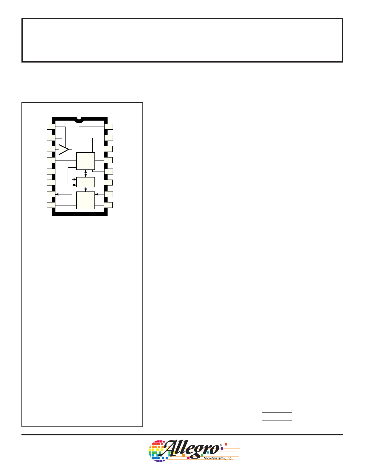
PHOTOELECTRIC SMOKE DETECTOR
WITH INTERCONNECT AND TIMER
The A5358CA is a low-current BiCMOS circuit providing all of the
required features for a photoelectric type smoke detector. This device
can be used in conjunction with an infrared photoelectric chamber to
16
TEST
HUSH
15
V
OSC. &
TIMING
DD
LOGIC
HORN
DRIVER
SS
– SUPPLY
14
TIMING RES.
13
OSC. CAP.
12
11
LED
10
FEEDBACK
HORN
Dwg. PC-007
2
sense scattered light from smoke particles. Special features are
incorporated in the design to facilitate calibration and testing of the
finished detector. The device is designed to comply with Underwriters
Laboratories Specification UL217 and British Standard BS 5446,
Part 1.
A variable-gain photo amplifier can be directly interfaced to an
infrared emitter/detector pair. The amplifier gain levels are determined
by two external capacitors that are then internally selected depending
on the operating mode. Low gain is selected during standby and timer
modes. During a local alarm this low gain is increased (internally) by
~10% to reduce false triggering. High gain is used during the pushbutton test and during standby to periodically monitor the chamber
sensitivity.
The internal oscillator and timing circuitry keeps standby power to
a minimum by sensing for smoke every 10 seconds in a 10 µs window.
A special three-stage speedup sensing scheme is incorporated to
minimize the time to an audible alarm and also to reduce false triggering. Also, two consecutive cycles of degraded chamber sensitivity are
required for a warning signal to occur.
ABSOLUTE MAXIMUM RATINGS
(Voltages are referenced to VSS)
Supply Voltage Range,
VDD.................................... -0.5 V to +15 V
Input Voltage Range,
VIN............................ -0.3 V to V
Input Current, IIN................................... 10 mA
Operating Temperature Range,
TA..................................... -25°C to +75°C
Storage Temperature Range,
TS................................... -55°C to +125°C
CAUTION: CMOS devices have input static
protection but are susceptible to damage if exposed
to extremely high static electrical charges.
+ 0.3 V
DD
The A5358CA is supplied in a low-cost 16-pin dual in-line plastic
package. It is rated for continuous operation over the temperature
range of -25°C to +75°C.
FEATURES
■ Interconnect Up to 50 Detectors
■ Piezoelectric Horn Driver
■ All Internal Low-Battery Detection
■ Power-ON Reset
■ Internal Timer & Control for Reduced Sensitivity
■ Built-In Circuits to Reduce False Triggering
■ 6 V to 12 V Operating Voltage Range
■ ESD-Protection Circuitry on All Pins
Always order by complete part number: A5358CA .

5358
PHOTOELECTRIC SMOKE DETECTOR
with INTERCONNECT and TIMER
FUNCTIONAL BLOCK DIAGRAM
DETECT
STROBE
+ SUPPLY
9 V
3
C1
1
C2
2
4
6IRED
– SUPPLY
14
V
SS
V
DD
5
BAND-GAP
REFERENCE
+
–
LOW BATTERY
PHOTO AMP
+
–
V
DD
I / O
7
LOGIC
V
DD
15
HUSH
POWER-ON
OSCILLATOR
& TIMING
RESET
16
TEST
FEEDBACK
10
9
HORN
2
8
HORN
1
11
LED
TIMING RES.
13
12
OSC. CAP.
+V
+V
Dwg. FC-006
115 Northeast Cutoff, Box 15036
Worcester, Massachusetts 01615-0036 (508) 853-5000
Copyright © 1995, 1996 Allegro MicroSystems, Inc.

5358
PHOTOELECTRIC SMOKE DETECTOR
with INTERCONNECT and TIMER
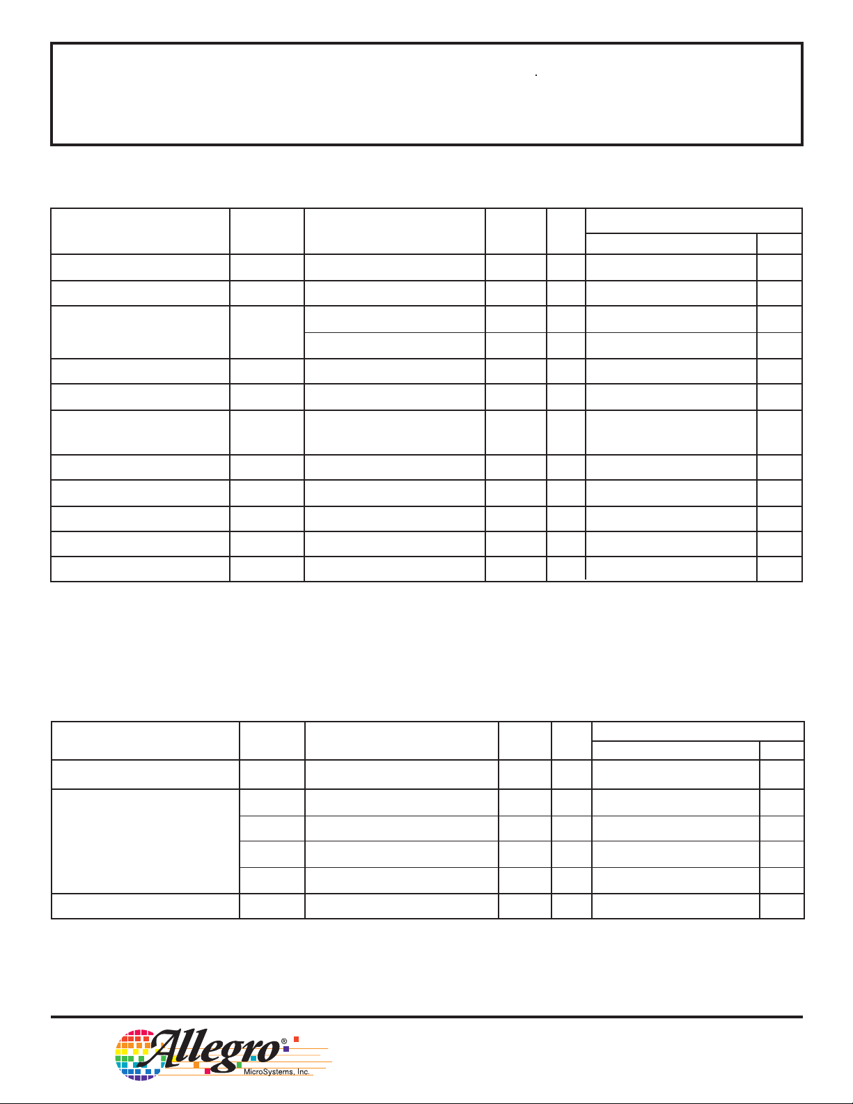
DC ELECTRICAL CHARACTERISTICS at T
= -25°C to +75°C*, V
A
(unless otherwise noted).
Test Limits
Characteristic Symbol Test Conditions Pin V
Supply Voltage Range V
Operating Supply Current I
Low-Level Input Voltage V
High-Level Input Voltage V
DD
DD
IH
Average Standby 5 12 – – 12 µA
Configured per Figure 1
During Strobe ON, I
OFF, 5 12 – – 2.0 mA
RED
Configured per Figure 1
During Strobe ON, I
ON, 5 12 – – 3.0 mA
RED
Configured per Figure 1
IL
5 – 6.0 – 12 V
79––1.5V
10 9 – – 2.7 V
16 9 – – 7.0 V
15 9 – – 0.5 V
793.2––V
10 9 6.3 – – V
16 9 8.5 – – V
15 9 1.6 – – V
= 0 V, in typical application
SS
Min. Typ. Max. Units
DD
Input Leakage High I
Input Leakage Low I
Input Pull-Down Current I
Low-Level Output Voltage V
High-Level Output Voltage V
Strobe Output Voltage V
IH
IL
IN
OL
OH
ST
VIN = VDD, Strobe Active, 1, 2 12 – – 100 nA
Pin 12 @ V
V
= V
IN
V
= VST, Strobe Active, 1, 2, 3 12 – – -100 nA
IN
Pin 12 @ V
V
= V
IN
DD
SS
DD
3, 10, 12 12 – – 100 nA
DD
10, 12 12 – – -100 nA
15, 16 12 – – -1.0 µA
V
= V
IN
DD
No Local Smoke, V
No Local Smoke, V
= V
IN
DD
= 17 V 7 12 – – 140 µA
IN
16, 15 9 0.25 – 10 µA
7920–80µA
IO = 10 mA 11 6.5 – – 0.6 V
= 16 mA 8, 9 6.5 – – 1.0 V
I
O
= 5 mA 13 6.5 – 0.5 – V
I
O
IO= -16 mA 8, 9 6.5 5.5 – – V
Inactive IO = -1 µA412
Active, I
= 100 µA to 500 µA4 9
O
VDD - 0.1
VDD - 5.25
––V
–
VDD - 4.75
V
Continued...
5358
PHOTOELECTRIC SMOKE DETECTOR
with INTERCONNECT and TIMER
DC ELECTRICAL CHARACTERISTICS, continued
Test Limits
Characteristic Symbol Test Conditions Pin V
Line Regulation ∆V
ST(∆VDD)
Strobe Temperature Coeff. α
Output Voltage V
I
RED
Line Regulation ∆V
Temperature Coefficient α
I
RED
IRED(∆VDD)
High-Level Output Current I
OFF Leakage Current High I
OFF Leakage Current Low I
Low V
Alarm Threshold V
DD
Common Mode Voltage V
Smoke Comparator Ref. Volt. V
ST
IRED
IRED
OH
OZ
OZ
DD(th)
IC
REF
Active, V
VDD = 6 V to 12 V 4 – – 0.01 – %/°C
Inactive IO = 1 µA, TA = +25°C 6 12 – – 0.1 V
Active I
Active, VDD = 6 V to 12 V 6 – -35 – dB
VDD = 6 V to 12 V 6 – – +0.40 – %/°C
VDD = Alarm, I/O active, 7 9 -4.0 – – mA
V
= VDD - 2 V
O
VO = V
VO = V
Any Alarm Condition 1, 2, 3 Any Alarm Condition Internal -
= 6 V to 12 V 4 – – -60 – dB
DD
= -6 mA, TA = +25°C 6 9 2.85 3.1 3.35 V
O
DD
SS
11, 13 12 – – 1.0 µA
11, 13 12 – – -1.0 µA
5 - 6.9 7.2 7.5 V
Min. Typ. Max. Units
DD
VDD - 4
VDD - 3.7
–
–
VDD - 2
VDD - 3.3
V
V
* Limits over the operating temperature range are based on characterization data.
Characteristics are production tested at +25°C only.
Typical values are at +25°C and are given for circuit design information only.
AC ELECTRICAL CHARACTERISTICS at T
= -25°C to +75°C*, V
A
(unless otherwise noted).
Test Limits
Characteristic Symbol Test Conditions Pin V
Oscillator Period t
Led Pulse Period t
Led Pulse Width t
osc
led1
t
led4
t
led6
t
led7
w(led)
No Local or Remote Smoke 11 9 39 – 48 s
Remote Smoke Only 11 9 None – – –
Local Smoke or Test 11 9 0.60 0.67 0.74 s
Timer Mode, No Alarm 11 9 9.67 10.8 11.8 s
12 9 9.4 10.5 11.5 ms
11 9 9.5 – 11.5 ms
= 0 V, in typical application
SS
DD
Min. Typ. Max. Units
Continued...
115 Northeast Cutoff, Box 15036
Worcester, Massachusetts 01615-0036 (508) 853-5000
 Loading...