

Allegro A3976KLB, A3973KB Datasheet
ADVANCED DATASHEET - 02/19/99
(Subject to change without notice)
Page 1 of 5
3976
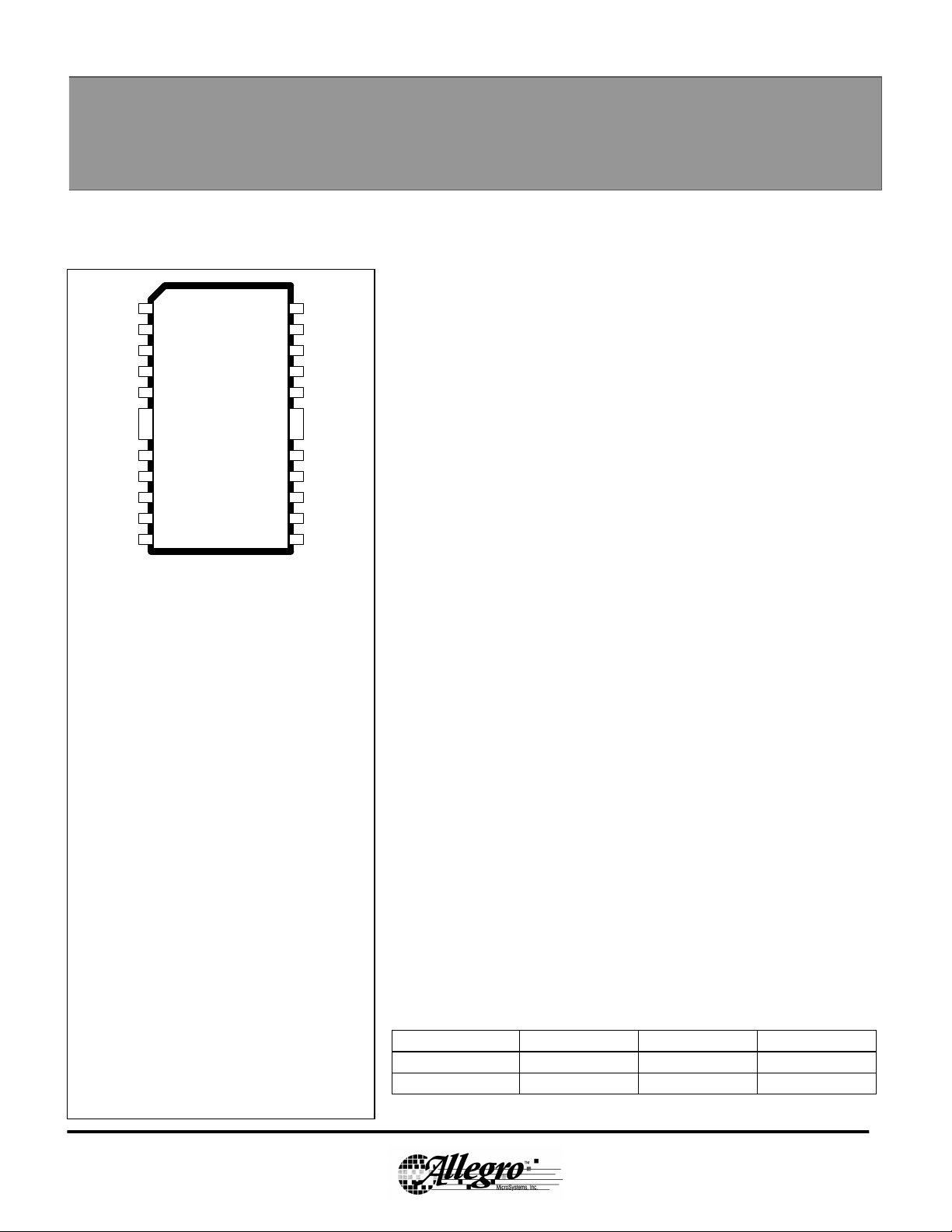
DUAL FULL BRIDGE
PROTECTED MOTOR DRIVER
ENABLE1
PHASE1
GROUND
GROUND
OUT1A
FAULT1
OUT1B
1
V
BB
2
3
4
n/c
5
n/c
A3976KLB
6
7
8
n/c
9
10
n/c
11
12
24
23
22
21
20
19
18
17
16
15
14
13
V
CC
ENABLE2
PHASE2
n/c
n/c
GROUND
GROUND
n/c
OUT2A
n/c
FAULT2
OUT2B
ABSOLUTE MAXIMUM RATINGS
at TA = +25°C
Operating Supply Voltage, VBB....................30 V
Non-Operating Supply Voltage.....................35 V
Output Current, I
Logic Supply Voltage, VCC..........................7.0 V
Fault Output Voltage ...................................7.0 V
Logic Input Voltage Range,
VIN..........................-0.3 V to V
Package Power Dissipation (TA = +25°C), P
A3976KLB..................................2.2 W
A3976KB....................................2.9 W
Operating Temperature Range,
TA..............................-40°°C to +125°°C
Junction Temperature, TJ.........................+150°°C
Storage Temperature Range,
TS...............................-55°°C to +150°°C
* Output current rating may be limited by duty cycle,
ambient temperature, and heat sinking. Under any set of
conditions, do not exceed the specified current rating or a
junction temperature of 150°C.
............................±±500 mA*
OUT
CC
+ 0.3 V
D
The A3976 is designed to drive both windings of a bipolar stepper
motor or bidirectionally control two DC Motors. Both H-Bridges are capable
of continuous output currents of up to +/- 500 mA and operating voltages to
30V. Free wheeling, substrate isolated diodes are included for output transient
suppression when switching motors or other inductive loads. For each bridge
the PHASE input controls load current polarity by selecting the appropriate
source and sink driver pair. The ENABLE input, when held high, enables the
respective output H-bridge. When both ENABLE pins are held low the device
will enter SLEEP mode and consume less than 100µA.
The 3976 is protected to ensure safe operation in harsh operating
environments and was designed specifically for automotive applications.
Protection circuitry will check for open or shorted load, motor lead short to
ground or supply, VBB overvoltage, VCC undervoltage, and thermal
shutdown. If any of these conditions are detected the outputs will be disabled
and fault information will be output to diagnostic pins FAULT1 and FAULT2.
The 3976 is supplied in a choice of two power packages, a 16-lead
plastic DIP with a copper batwing tab (suffix ‘B’), and a 24-lead plastic SOIC
with a copper batwing tab (suffix ‘LB’). In both cases, the power tab is at
ground potential and needs no electrical isolation.
FEATURES
n 30 V , ±500 mA Continuous Output Rating
n 35V Load Dump Survival
n Output Short Circuit Protection
n Coded Fault Diagnostic Outputs
n Low Current Standby Mode
n Open Load Monitor
n Low Current Standby Mode
n VBB Over Voltage Shutdown
n Internal Thermal Shutdown Circuitry
n Internal Low Parasitic Free Wheeling Diodes
n Crossover Current Protection
PART NUMBER PACKAGE R
ØJA
A3976KLB 24 Lead SOIC 56°°C/W 6°°C/W
A3973KB 16 Lead DIP 43 °°C/W 6°°C/W
R
ØJT
Page 2 of 5
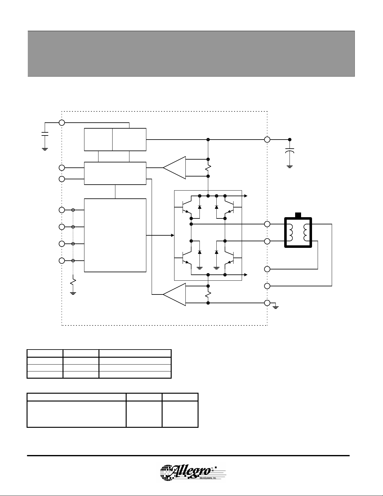
3976 Dual Protected PWM Motor Driver
Functional Block Diagram
(one of two bridges shown)
V
CC
FAULT1
FAULT2
PHASE1
ENABLE1
PHASE2
ENABLE2
Thermal
Shutdown
Diagnostic Logic
Input Pull Down
Over/Under
Voltage
Monitor
CONTROL
LOGIC
Short to Supply
Monitor
Short to Ground
Monitor
To Bridge 2
To Bridge 2
V
BB
OUT1A
OUT1B
OUT2A
OUT2B
GROUND
Input Logic
PHASE ENABLE OUTA OUTB
X 0 Off Off
0 1 Low High
1 1 High Low
Fault Logic
Fault Condition FAULT1 FAULT2
Thermal Shutdown Low Low
Short to Battery or Open Load Low High
Short to Ground High Low
Normal Operation High High
 Loading...