

3848
DUAL-CONVERSION AM RECEIVER
3848
DUAL-CONVERSION AM RECEIVER
Providing the AM signal processing functions for an electronically
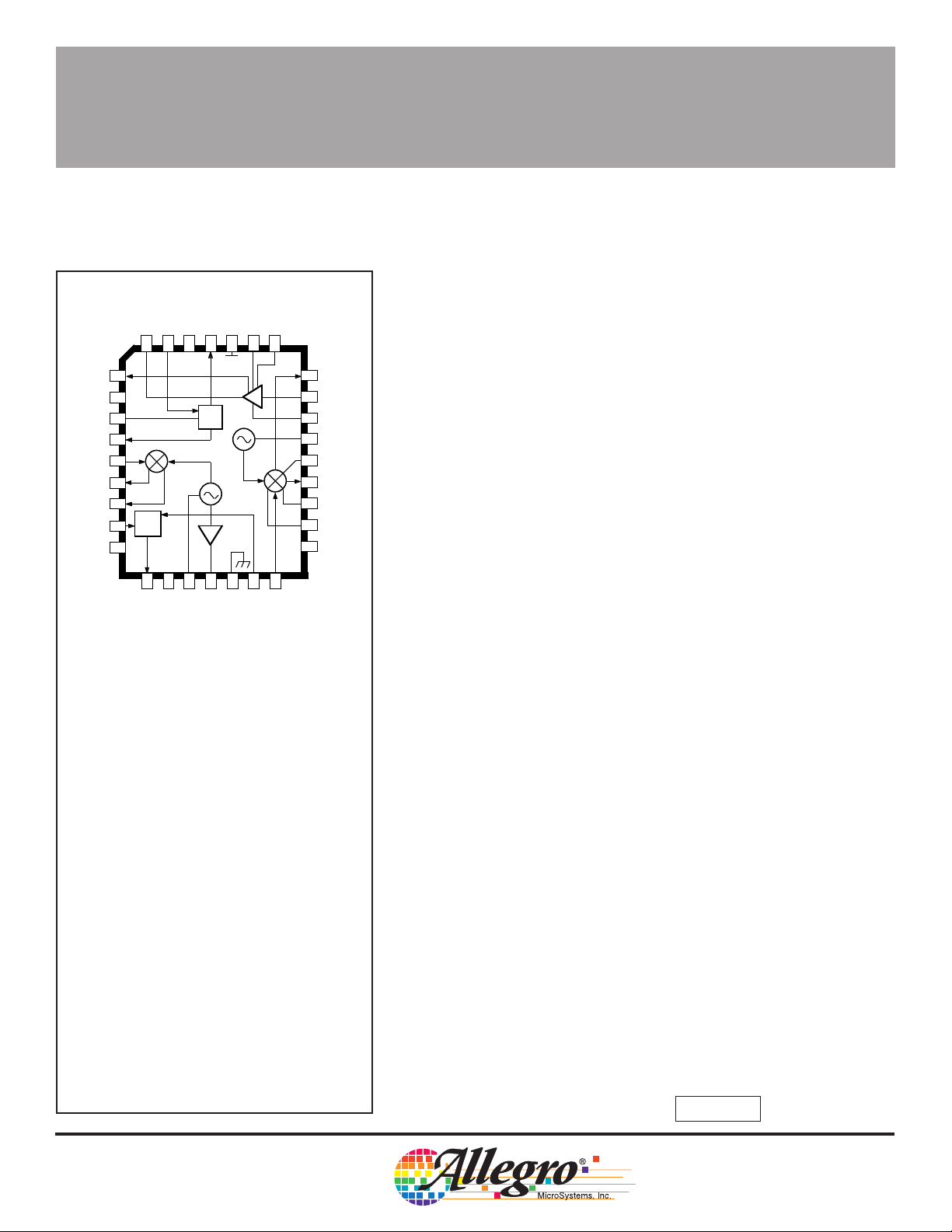
tuned AM receiver (ETR), the A3848EEQ includes two balanced
mixers, a crystal local oscillator, an L/C-tuned local oscillator, oscillator
buffer, IF amplifier, AM detector, scan control detectors, and a switchable voltage regulator. This dual-conversion device typically mixes the
incoming RF up to a first IF of 10.7 MHz, then down to 450 kHz, and
B
then detects the audio. The addition of a JFET matched to a whip
antenna, RF low-pass filter, IF selectivity, and audio stages gives a
complete AM radio which can be used in automotive receivers. The
frequency-detecting stop circuit is also capable of recovering narrowband FM, making it useful for scanners or weather band radio applica-
A
tions. Two AGC and field-strength indicator modes provide special
features for scanning.
The A3848EEQ uses the dual criteria of frequency and amplitude
for establishing a valid stop. Tuning accuracy (frequency criterion) is
established by evaluating phase shift across the detector coil. The
circuitry is similar to that used in FM discriminators. Because this
detection system is phase operated, it remains effective even in the
presence of strong signals, which can cause false stops in systems
using narrow-band filters. The amplitude criterion for stop is determined by evaluating the IF level. It includes a unique circuit that
removes the effect of the AGC action. This allows the AGC tuning
components to be selected for low-frequency audio performance
without compromising scanning speed.
REGULATOR
AFC OUT
STOP
MIX 1 IN
MIX 1 OUT
MIX 1 OUT
WB AGC 1 IN
RESET
DETECTOR
SUPPLY
IF OUT
4
5
FSI
6
V
REG
7
8
9
10
A
11
B
WB
12
AGC
13
V
14
WB AGC OUT
2
3
V
CC
REF
15
16
REFERENCE
AUDIO OUT
1
DET
17
OSC COIL
HIGH-LEVEL
GROUND
32
SUB
18
GROUND
LOW-LEVEL
OSC BUFFER
DECOUPLE
IF BIAS
31
30
29
28
27
26
25
24
23
22
21
19
20
MIX 2 IN
WB AGC 2 IN
Dwg. No. PS-012-1
MIX 2 OUT
IF
AGC (MUTE)
CRYSTAL
AGC RATE 2
MIX 2 OUT
MIX 2 E
B
MIX 2 E
B
MIX 2
BYPASS
Dwg. PS-012-1
Data Sheet
27121.15
In the normal AGC mode (AGC RESET low), a slow, narrow-band
field-strength indicator (FSI) is provided for controlling signal-dependent functions such as stereo blending. A fast AGC mode (AGC
RESET high) resets the AGC holding capacitors to maximum gain.
This mode allows cataloging station strengths quickly during a band
sweep.
This AM signal processor is packaged in a rectangular, 32-lead,
ABSOLUTE MAXIMUM RATINGS
DISCONTINUED PRODUCT
Supply Voltage, VCC. . . . . . . . . . . . . . 12 V
Package Power Dissipation, P
Operating Temperature Range,
— FOR REFERENCE ONLY
TA. . . . . . . . . . . . . . . -40°C to +105°C
Storage Temperature Range,
TS. . . . . . . . . . . . . . . -65°C to +150°C
. . . . 1.2 W
D
plastic, leaded chip carrier (PLCC) for surface-mount applications and
is rated for operation over the temperature range of -40°C to +105°C
are available on special order.
FEATURES
■ Low Noise Figure ■ Field-Strength Indicator
■ Balanced Mixers ■ Buffered Oscillator
■ High Dynamic Range First Mixer ■ Fast Scan Mode
Always order by complete part number: A3848EEQ .

3848
DUAL-CONVERSION AM RECEIVER
ELECTRICAL CHARACTERISTICS at T
f
= 450 kHz, Vin = 10 mV; fm = 1 kHz , Mod = 30% (except as noted).
if2
= +25°C, V
A
= 10 V, fo = 1 MHz, f
CC
= 10.7 MHz,
if1
Limits
Characteristic Symbol Test Conditions Min Typ Max Units
Supply Current I
Sensitivity V
Usable Sensitivity V
Recovered Audio V
CC
in
in
out
I2, Vin = 0 — 50 65 mA
I
, Vin = 0, V27 = 0 (Muted) — 1.0 6.0 mA
2
V
= 50 mV — 6.0 10 µV
out
S + N/N = 20 dB — 14 21 µV
165 215 265 mV
Total Harmonic Dist. THD Mod = 90% — 0.4 2.0 %
Oscillator Output V
Stop Output Voltage V
Stop Sensitivity V
Stop Bandwidth BW
Wide-Band AGC V
Field-Strength
V
Indicator
Output Voltage
(unmodulated,
AGC Reset Low)
Field-Strength
V
Indicator
Output Voltage
(unmodulated,
AGC Reset High)
Overload V
o
STP
stp
STP
AGC
FSI
FSI
in
V
17
80 120 — mV
V8, Vin = 0 4.7 5.0 — V
, Mod = 0% — 0.10 0.16 V
V
8
V12 = 2.5 V, Mod = 0% 30 45 60 µV
V8 = 2.5 V, = 0% 5.0 6.5 8.0 kHz
Vin = 0 5.0 6.7 8.0 V
V
= 11 mV, Mod = 0% 3.7 5.0 — V
in
V
= 26 mV, Mod = 0% — — 1.0 V
in
Vin = 0 — 0.1 0.4 V
V
= 30 µV, Mod = 0% 0.25 0.60 1.05 V
in
V
= 100 µV, Mod = 0% 1.1 1.6 2.2 V
in
= 1 mV, Mod = 0% 1.8 2.5 3.2 V
V
in
V
= 10 mV, Mod = 0% 3.1 3.7 4.4 V
in
Vin = 0 — — 0.5 V
= 30 µV, Mod = 0% 0.9 1.1 1.5 V
V
in
V
= 100 µV, Mod 0% 1.3 1.6 2.0 V
in
V
= 1 mV, Mod = 0% 2.3 2.9 3.5 V
in
= 10 mV, Mod = 0% 2.5 3.7 4.0 V
V
in
V
= 3% THD, Mod = 90% 60 100 — mV
out
First Mixer (Note 2) 350 450 — mV
-3dB Limiting V
IF Output Voltage V
FM Recovered Audio V
in
out
out
Signal to Noise Ratio S+N/N V
AGC Figure of Merit FOM Ref. at V
Mod = 3 kHz peak deviation — 12 — µV
Vin = 1 mV 200 250 320 mV
V7, Mod = 3 kHz peak deviation — 380 — mV
= 1 mV 50 53 — dB
in
V
= 10 mV 53 56 — dB
in
= 10 mV, Vin for V
in
= -10 dB 7.0 10 14 µV
out
115 Northeast Cutoff, Box 15036
Worcester, Massachusetts 01615-0036 (508) 853-5000
W
Copyright © 1993, Allegro MicroSystems, Inc.
Continued next page...
 Loading...