

RF IN
RF BYPASS
RF BIAS
RF AGC
AUDIO DELAY
AUDIO BLANK
TIME (R)
NO
CONNECT
AUDIO BLANK
TIME (C)
AUDIO OUT
AUDIO IN
Data Sheet
27126B*
3845
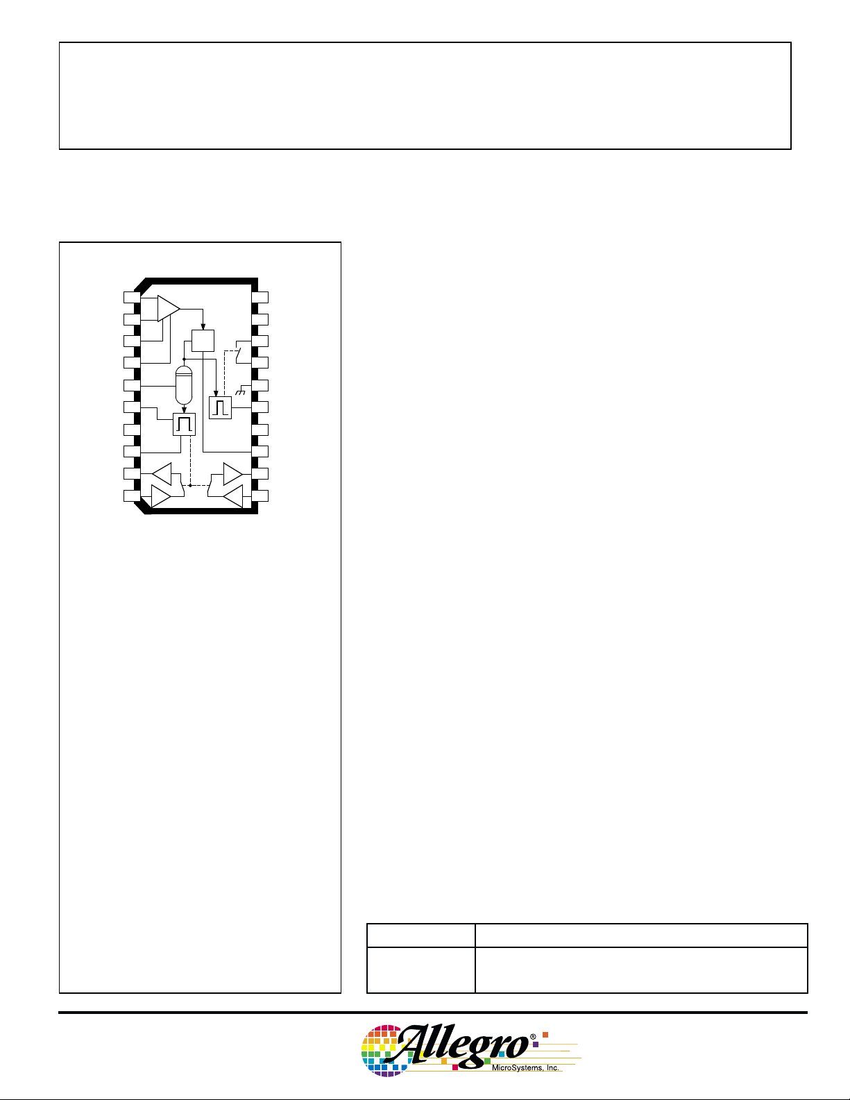
AM NOISE BLANKER
This noise blanker integrated circuit contains all of the necessary
circuitry for adding an extremely efficient (patented) noise-blanking
CC
NC
NC
SUPPLY
20
NO
19
CONNECT
RF GATE
18
LOW
RF GATE
17
HIGH
GROUND
16
RF BLANK
15
TIME
NO
14
CONNECT
NOISE
13
DIFFERENTIATOR
AUDIO OUT
12
11
AUDIO IN
2
2
Dwg. PS-003-1A
1
2
3
4
5
6
NC
7
8
9
1
10
1
V
DET
technique to any type of AM tuner or receiver with RF input frequencies (or a first IF) to 30 MHz. The A3845ELW and A3845SLW
feature dual audio channels and are intended for AM-stereo or independent sideband applications.
A high input impedance, high-gain, broadband RF amplifier
permits these devices to be directly connected to the RF stage of a
tuner. Internal AGC circuitry ensures that the noise detection threshold
remains constant with changes in input signal level. The RF gate
response time is sufficiently fast to blank the noise pulse at the output
of the mixer before the IF filter. Short blanking times effectively
suppress most of the interfering noise. Residual audio noise is removed by an audio sample-and-hold gate. The RF blanking time,
audio gate delay time, and audio gate blanking time can all be independently adjusted to suit the particular application.
ABSOLUTE MAXIMUM RATINGS
at TA = +25°C
Supply Voltage, VCC. . . . . . . . . . . . . . 12 V
Package Power Dissipation,
. . . . . . . . . . . . . . . . . . . . . . . 1.78 W
P
D
Operating Temperature Range, T
Suffix ‘ELW’ . . . . . . . . -40°C to +85°C
Suffix ‘SLW’ . . . . . . . . -20
Storage Temperature Range,
. . . . . . . . . . . . . . . . -55°C to +125°C
T
S
A
°C to +85°C
These AM noise blankers are packaged in plastic SOICs and are
rated for operation over the a standard temperature range of -20°C to
+85°C (suffix ‘SLW’) or an extended temperature range to -40°C
(suffix ‘ELW’).
FEATURES
■ RF Blanking to 30 MHz
■ Single-Channel or Stereo Audio Blanking
■ Adjustable RF and Audio Blanking Time
■ Adjustable Audio Blanking Delay
■ Sample-and-Hold MOS Audio Gates
■ Internal Voltage Regulation
■ Minimum External Components
APPLICATIONS
■ AM and AM-Stereo Automotive Radios
■ CB Transmitter/Receivers
■ Short-Wave Receivers
■ Mobile Communications Equipment
Always order by complete part number:
Part Number Function
A3845ELW Stereo Noise Blanker, Extended Temp. Range
A3845SLW Stereo Noise Blanker, Standard Temp. Range
3845
AM NOISE BLANKER
RF IN
RF
RF BYPASS
SUPPLY
1
2
RF BIAS
3
RF AGC
4
GROUND
16
20
19 14 7
NO CONNECTION
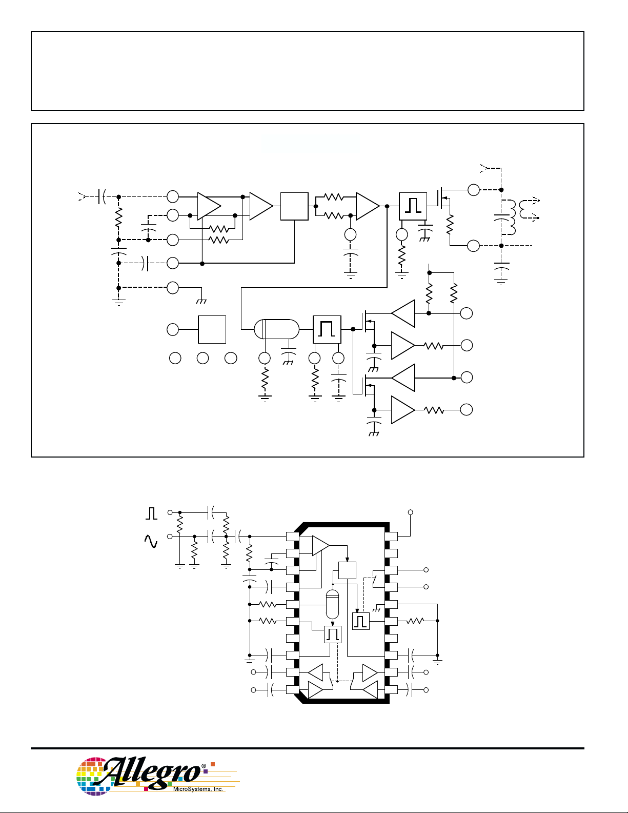
FUNCTIONAL BLOCK DIAGRAM
dV/dt DET
PEAK
DET
13
NOISE
DIFFERENTIATOR
REG
5
69 pF
AUDIO DELAY
6 8
15
RF BLANK TIME
+4 V
100 kΩ
1 kΩ
69 pF
MIXER
100 kΩ
OUT
17
RF GATE
HIGH
40 Ω
18
RF GATE
LOW
AUDIO IN
10
AUDIO OUT
9
AUDIO IN
11
IF
IN
V
CC
1
1
2
NOISE
RF
0.005
60.4 Ω
0.01 0.01
93.1 Ω
187 Ω
AUDIO OUT
AUDIO IN
AUDIO BLANK TIME
1 kΩ
12
AUDIO OUT
2
Dwg. FS-004-1A
TEST CIRCUIT
SUPPLY
267 Ω
V
1
10 µF
+
R
5
R
6
C
8
0.1
2
0.1
3
4
5
6
NC
7
8
9
10
DET
2 kΩ
0.1
1
0.1
1
20
CC
NC
19
R
15
0.001
0.1
RF BYPASS
MIXER OUT
AUDIO OUT
AUDIO IN
Dwg. ES-007-1A
2
2
18
17
16
15
NC
14
13
0.1
12
11
Note that the noise-pulse input is attenuated 20 dB by the test circuit.
115 Northeast Cutoff, Box 15036
Worcester, Massachusetts 01615-0036 (508) 853-5000
Copyright © 1988, 2000 Allegro MicroSystems, Inc.
AM NOISE BLANKER
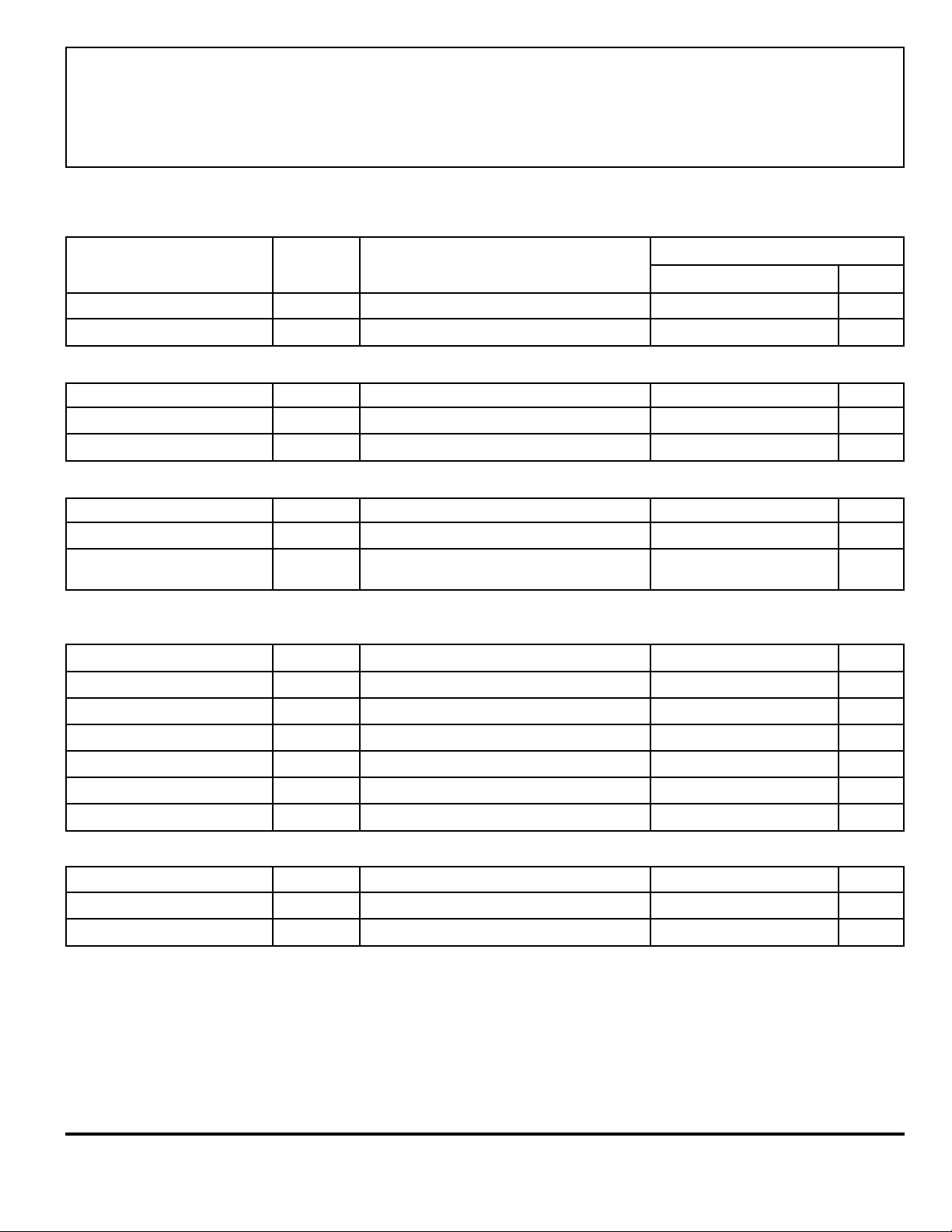
ELECTRICAL CHARACTERISTICS over operating temperature range, at VCC = 7.5 V to
11 V, frf = 1 MHz, Noise (f
) = 500 Hz Square Wave, faf = 1 kHz, Test Figure.
noise
3845
Test
Characteristic Leads Test Conditions Min. Typ. Max. Units
Supply Voltage Range 20 Operating 7.5 9.0 12 V
Quiescent Supply Current 20 VRF = 0 — 15 22 mA
RF INPUT AMPLIFIER:
Trigger Threshold 1 Noise Pulse Amplitude for VRF = 0 45 100 240 µV
Modulation Threshold 1 Noise Pulse Modulation for VRF = 1 mV 35 75 220 %
Detector Rise Time 13 C13 = 0 — 500 — ns
RF SWITCH:
ON Resistance 17-18 — 30 100 Ω
OFF Resistance 17-18 — 100 — kΩ
Time Delay 1-17
AUDIO SWITCHES:
Attenuation 10-9, 11-12 55 80 _ dB
Noise 9, 12 — 1.5 12 mVpp
From Beginning of RF Pulse
to Beginning of RF Blanking
— 1.5 5.0 µs
Limits
Crosstalk 9, 12 40 60 — dB
Gain 10-9, 11-12 -1.2 -0.3 0 dB
Total Harmonic Distortion 9, 12 Vaf =700 mV, V
Input Impedance 10, 11 — 100 — kΩ
Output Impedance 9, 12 — 1.0 — kΩ
BLANKING TIMERS:
RF Blanking 17 R15 = 350 kΩ 35 60 75 µs
Audio Delay 9 R5 = 350 kΩ 30 55 67 µs
Audio Blanking 9 R6 = 110 kΩ, C8 = 0.0012 µF 210 250 400 µs
= 0 — <0.1 1.0 %
noise
www.allegromicro.com
 Loading...