


查询A3240ELTTR供应商
3240
CHOPPER-STABILIZED, PRECISION
HALL-EF FECT SWITCH
Data Sheet
27621.20c
Suffi x ‘–LT’ & ‘–UA’ Pinning
(SOT89/TO-243AA & ultra-min SIP)
X
PTCT
V
CC
1
SUPPLY
Pinning is shown viewed from branded side.
32
GROUND
Dwg. PH-003-2
OUTPUT
The A3240-- Hall-effect switch is an extremely temperature-stable
and stress-resistant sensor especially suited for operation over extended
tem per a ture ranges to +150°C. Superior high-temperature per for mance
is made possible through dynamic offset cancellation, which reduces the
residual offset voltage normally caused by device overmolding, tem per a ture de pen den cies, and thermal stress.
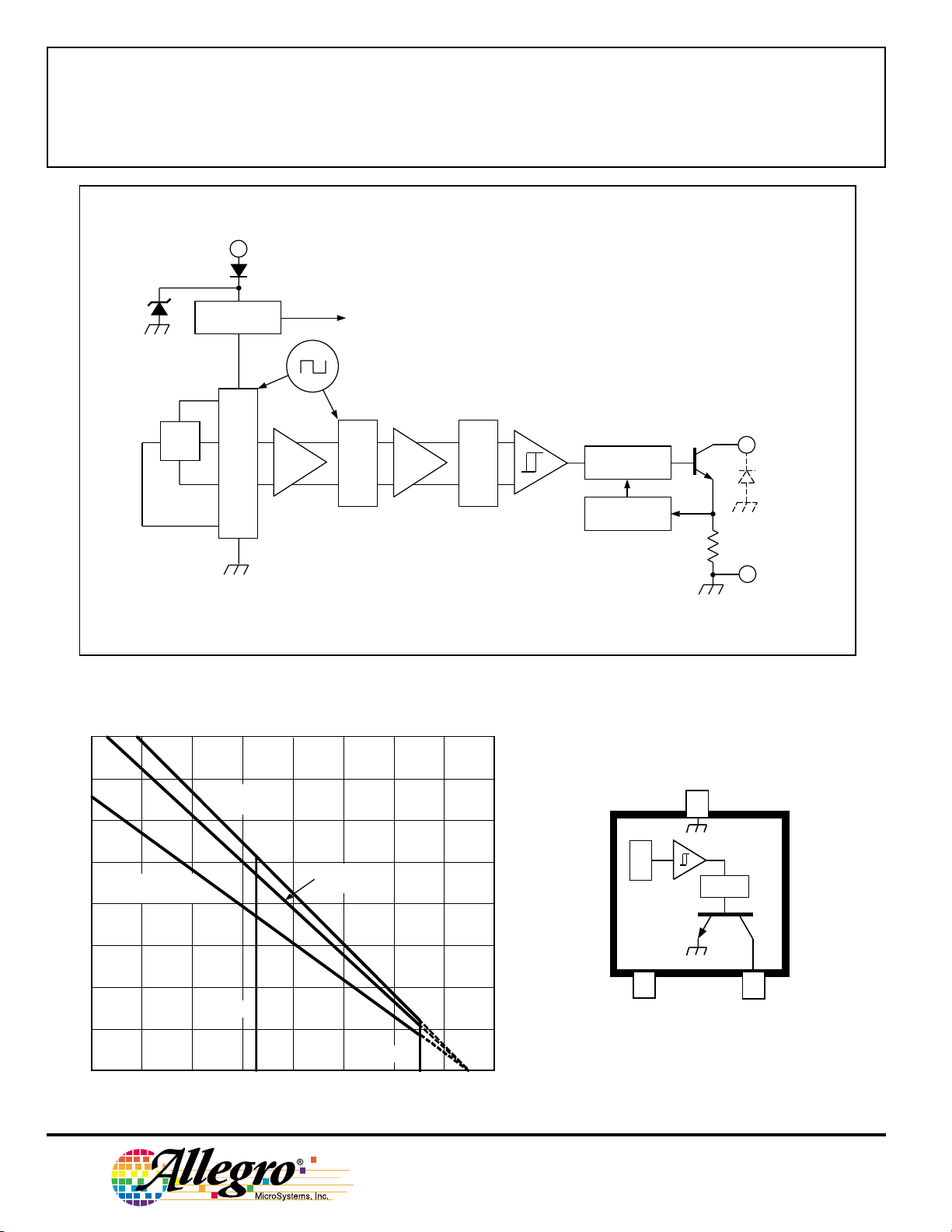
The device includes on a single silicon chip a voltage regulator, Hallvoltage generator, small-signal amplifi er, chopper sta bi li za tion, Schmitt
trigger, and a short-circuit protected open-collector output to sink up to
25 mA. A south pole of suffi cient strength will turn the output on. An
on-board regulator permits operation with supply voltages of 4.2 to 24
volts.
Three package styles provide a magnetically op ti mized pack age for
most ap pli ca tions. Package type LH is a modifi ed SOT23W surface-
mount package, LT is a miniature SOT89/TO-243AA transistor package
for surface-mount applications; while UA is a three-lead ultra-mini-SIP
for through-hole mounting. The LH and UA packages are also available
in a lead (Pb) free version (suffix, –T) , with a 100% matte tin plated
leadframe.
ABSOLUTE MAXIMUM RATINGS
at TA = +25°C
Supply Voltage, VCC .......................... 26.5 V
Reverse Battery Voltage, V
Magnetic Flux Density, B............ Unlimited
Output OFF Voltage, V
Continuous Output Current,
I
Reverse Output Current, I
Package Power Dissipation, PD See Graph
Junction Temperature, TJ ................ +170°C
Operating Temperature Range, T
Range ‘L’.................... -40°C to +150°C
Storage Temperature Range,
TS .............................. -65°C to +170°C
*Internal current limiting is intended to protect
the device from output short circuits.
......................................... 25 mA*
OUT
Range ‘E’ ..................... -40°C to +85°C
.......... -30 V
RCC
.................. 26 V
OUT
......... -50 mA
OUT
A
FEATURES
■ Resistant to Physical Stress
■ Superior Temperature Stability
■ Output Short-Circuit Protection
■ Operation From Unregulated Supply
■ Reverse Battery Protection
■ Sol id-State Reliability
■ Small Size

Product Selection Guide
Part Number Pb-free Packing* Mounting
A3240ELHLT – 7-in. reel, 3000 pieces/reel Surface Mount
A3240ELHLT-T Yes 7-in. reel, 3000 pieces/reel Surface Mount
A3240ELT – Bulk, 500 pieces/bag Surface Mount
A3240ELTTR – 7-in. reel, 3000 pieces/reel Surface Mount
A3240EUA – Bulk, 500 pieces/bag SIP through hole
A3240EUA-T Yes Bulk, 500 pieces/bag SIP through hole
A3240LLHLT – 7-in. reel, 3000 pieces/reel Surface Mount
A3240LLHLT-T Yes 7-in. reel, 3000 pieces/reel Surface Mount
A3240LLT – Bulk, 500 pieces/bag Surface Mount
A3240LLTTR – 7-in. reel, 3000 pieces/reel Surface Mount
A3240LUA – Bulk, 500 pieces/bag SIP through hole
A3240LUA-T Yes Bulk, 500 pieces/bag SIP through hole
*Contact Allegro for additional packing options.
3240
CHOPPER-STABILIZED,
PRECISION
HALL-EFFECT SWITCH
Ambient, T
(ºC)
–40 to 85
–40 to 150
A
B
RP(MIN)
(G)
5.0 50
B
OP(MAX)
(G)
www.allegromicro.com
2
3240
CHOPPER-STABILIZED,
PRECISION
HALL-EFFECT SWITCH
SUPPLY
FUNCTIONAL BLOCK DIAGRAM
800
700
600
X
REG.
DYNAMIC
OFFSET CANCELLATION
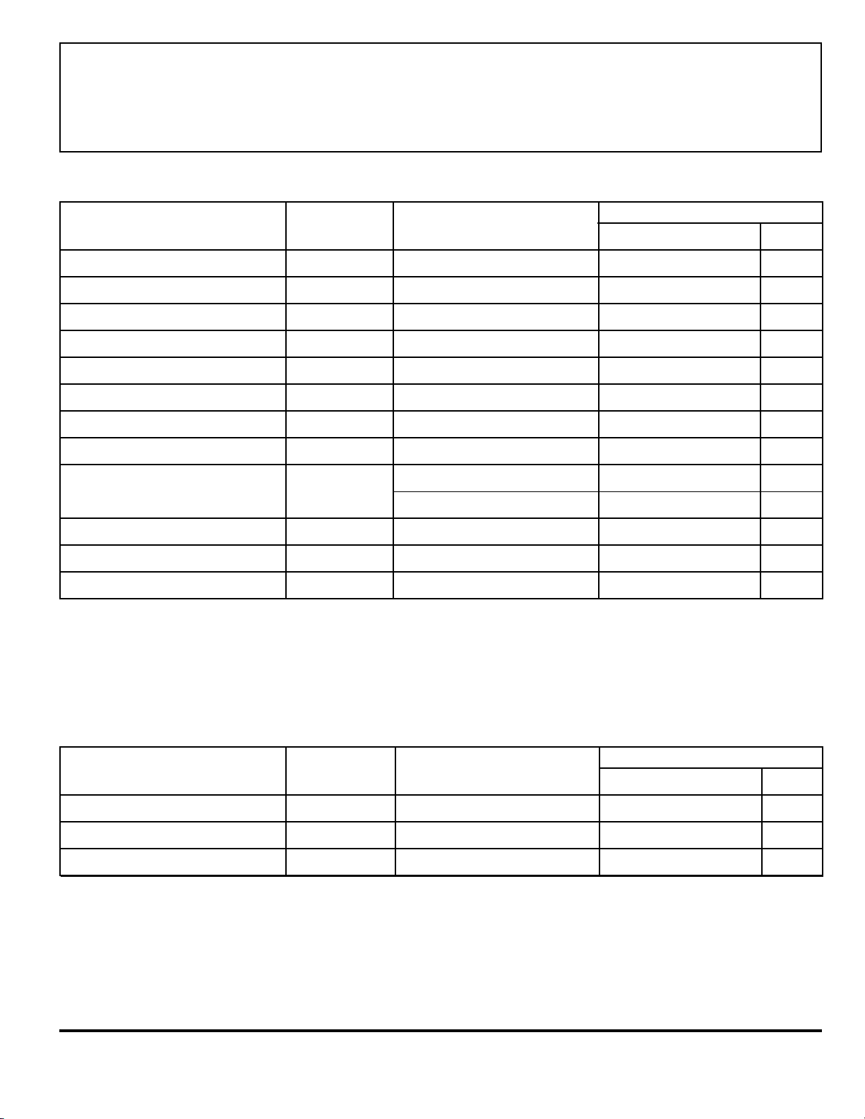
Suffix "–UA"
R
θJA
= 165°C/W
TO ALL
SUBCIRCUITS
& HOLD
SAMPLE
FILTER
LOW-PASS
OUTPUT
CONTROL
CURRENT
LIMIT
<1Ω
GROUND
Dwg. FH-020-1
Suffix ‘–LH’ Pinning
(SOT23W)
3
500
Suffix "–LH"
R
θJA
400
300
200
100
ALLOWABLE PACKAGE POWER DISSIPATION in MILLIWATTS
0
20 60 100 140
= 228°C/W
Suffix "E–"
40 80 120 180
AMBIENT TEMPERATURE in °°°°C
3
Suffix "–LT"
R
θJA
= 180°C/W
V
Suffix "L–"
160
Dwg. GH-046-2D
115 Northeast Cutoff, Box 15036
Worcester, Massachusetts 01615-0036 (508) 853-5000
Copyright © 2000, 2003, 2004 Allegro MicroSystems, Inc.
X
PTCT
CC
12
SUPPLY
GROUND
Dwg. PH-003-4
OUTPUT
3240
CHOPPER-STABILIZED,
PRECISION
HALL-EFFECT SWITCH
ELECTRICAL CHARACTERISTICS over operating temperature range.
Limits
Characteristic Symbol Test Conditions Min. Typ. Max. Units
Supply Voltage Range V
Output Leakage Current I
Output Saturation Voltage V
OUT(SAT)
Output Current Limit I
Power-On Time t
Chopping Frequency f
Output Rise Time t
Output Fall Time t
Supply Current I
CC
OFF
OM
po
C
r
f
CC
Operating, TJ < 165°C
V
= 24 V, B < B
OUT
I
= 20 mA, B > B
OUT
B > B
OP
VCC > 4.2 V – – 50 µs
RL = 820 Ω, CL = 20 pF – 0.2 2.0 µs
RL = 820 Ω, CL = 20 pF – 0.1 2.0 µs
B < BRP, VCC = 12 V – 3.0 6.0 mA
1
RP
OP
B > BOP, VCC = 12 V – 4.0 6.0 mA
Reverse Battery Current I
CC
Zener Voltage VZ + V
Zener Impedance zz + z
D
D
V
= -30 V – – -5.0 mA
RCC
ICC = 15 mA, TA = 25°C 283237 V
ICC = 15 mA, TA = 25°C–50–Ω
NOTES: 1. Maximum voltage must be adjusted for power dissipation and junction temperature.
2. BOP = operate point (output turns on); BRP = release point (output turns off).
3. Typical Data is at TA = +25°C and VCC = 12 V and is for design information only.
4.2–24V
––10µA
– 185 500 mV
30 – 60 mA
– 340 – kHz
MAGNETIC CHARACTERISTICS over operating supply voltage and temperature ranges.
Limits
Characteristic Symbol Test Conditions Min. Typ. Max. Units
Operate Point B
Release Point B
Hysteresis B
OP
RP
hys
BOP - B
RP
NOTES: 1. Typical Data is at TA = +25°C and VCC = 12 V and is for design information only.
2. 1 gauss (G) is exactly equal to 0.1 millitesla (mT).
www.allegromicro.com
–3550G
5.0 25 – G
–10– G
4
 Loading...