

查询3163供应商
3163
FOR 2-WIRE APPLICATIONS
HALL-EFFECT SWITCH
Data Sheet
27621.31†
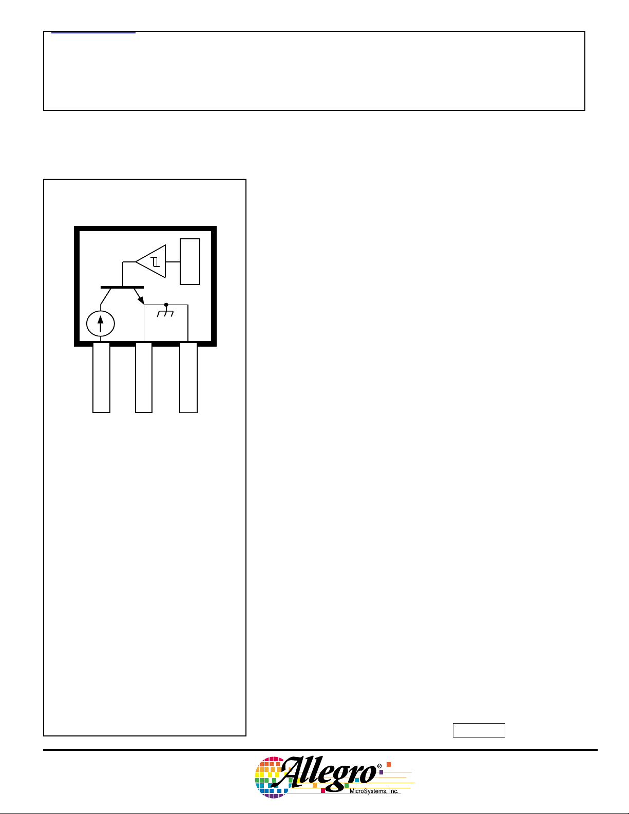
Suffix 'UA' Pinning
(ultra-mini SIP)
X
1
SUPPLY
GROUND
32
This Hall-effect switch is a monolithic integrated circuit designed to
operate continuously over extended temperatures to +85°C. The unipolar switching characteristic makes this device ideal for use with a simple
bar or rod magnet. The A3163ELT and A3163EUA are identical except
for package.
Each device includes a voltage regulator for operation with supply
voltages of 3.5 to 24 volts, reverse-battery protection, quadratic Hallvoltage generator for low offset, temperature compensation circuitry,
small-signal amplifier, Schmitt trigger, and a constant-current opencollector output, wired internally for true 2-wire operation. Noise
radiation is limited by control of the output-current slew rate.
Two package styles provide a magnetically optimized package for
most applications. Suffix ‘LT’ is a miniature SOT89/TO-243AA transistor package for surface-mount applications; suffix ‘UA’ is a three-lead
ultra-mini SIP for through-hole mounting; it is also available with lead
forming for surface-mount applications (suffix 'UA-TL').
GROUND
Dwg. PH-003-7A
Pinning is shown viewed from branded side.
ABSOLUTE MAXIMUM RATINGS
at T
= +25°C
A
Supply Voltage, VCC................ 26.5 V
Reverse Battery Voltage, V
Magnetic Flux Density, B ..... Unlimited
Package Power Dissipation, PD See Graph
Junction Temperature, T
Operating Temperature Range,
........................ -40°C to +85°C
T
A
Storage Temperature Range,
T
...................... -65°C to +170°C
S
.... -16 V
RCC
....... +170°C
J
FEATURES and BENEFITS
■ Internal Current Regulator for 2-Wire Operation
■ Output Slew Rate Controlled
■ 3.5 V to 24 V Operation … Needs Only An Unregulated Supply
■ Reverse Battery Protection
■ Excellent Temperature Stability
■ Activate with Small, Commercially Available Permanent Magnets
■ Small Size
■ Solid-State Reliability … No Moving Parts
■ Resistant to Physical Stress
Always order by complete part number, e.g., A3163ELT .
3163
HALL-EFFECT SWITCH
FOR 2-WIRE APPLICATIONS
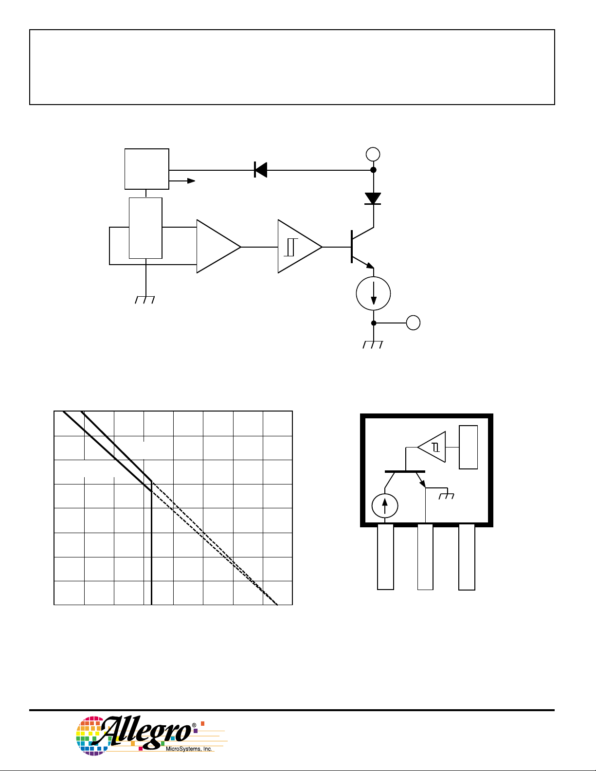
FUNCTIONAL BLOCK DIAGRAM
REG.
X
SUPPLY
GROUND
Dwg. FH-017-1
800
700
Suffix "UA"
R
θJA
600
500
400
300
200
100
ALLOWABLE PACKAGE POWER DISSIPATION in MILLIWATTS
0
Suffix "LT"
R
θJA
= 180°C/W
20 60 100 140
40 80 120 180
= 165°C/W
AMBIENT TEMPERATURE in °°°°C
160
Dwg. GH-046-6A
Suffix 'LT' Pinning
(SOT89/TO-243AA)
X
NC
1
SUPPLY
GROUND
32
Dwg. PH-003-6
CONNECTION
NO (INTERNAL)
Pinning is shown viewed from branded side.
2
115 Northeast Cutoff, Box 15036
Worcester, Massachusetts 01615-0036 (508) 853-5000
Copyright © 2002 Allegro MicroSystems, Inc.
3163
HALL-EFFECT SWITCH
FOR 2-WIRE APPLICATIONS
ELECTRICAL CHARACTERISTICS over operating voltage and temperature ranges.
Limits
Characteristic Symbol Test Conditions Min. Typ. Max. Units
Supply Voltage V
Output Current I
CC
OUT(H)
I
OUT(L)
Output Slew Rate di/dt C
Output Settling Time t
Reverse Battery Current I
sd
CCR
Operating 3.5 — 24 V
B > B
OP
B < B
RP
= 20 pF — 7.0 20 mA/µs
L
C
= 20 pF — — 20 µs
L
V
= -16 V — — -15 mA
RCC
12 14 17 mA
5.0 5.6 6.9 mA
MAGNETIC CHARACTERISTICS over operating supply voltage and temperature ranges.
Limits
Characteristic Symbol Min. Typ. Max. Units
Operate Point (output turns on) B
Release Point (output turns off) B
Hysteresis (BOP – BRP)B
NOTES: 1. Typical Data is at T
= +25°C and V
A
= 12 V and is for design information only.
CC
OP
RP
hys
2. 1 gauss (G) is exactly equal to 0.1 millitesla (mT).
– 98 160 G
30 79 – G
5.0 19 40 G
www.allegromicro.com
3
3163
HALL-EFFECT SWITCH
FOR 2-WIRE APPLICATIONS
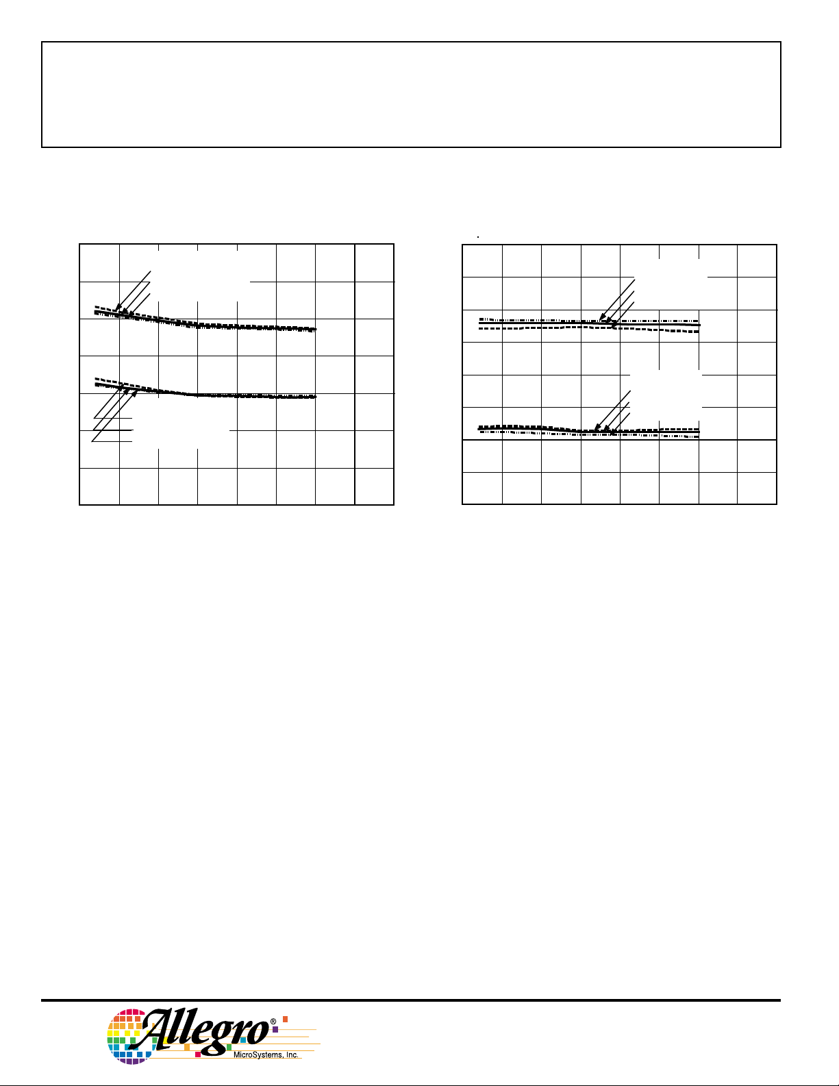
TYPICAL OPERATING CHARACTERISTICS
SWITCH POINTS LOAD CURRENT
120
OPERATE POINT, B
110
100
90
80
70
SWITCH POINTS in GAUSS
60
VCC = 3.5 V
CC
V
CC
V
RELEASE POINT, B
VCC = 3.5 V
V
CC
= 12 V
CC
= 24 V
V
= 12 V
= 24 V
OP
RP
20
15
) in mA
OUT
10
5.0
LOAD CURRENT (I
I
OUT(H)
, B > B
VCC = 24 V
CC
= 12 V
V
CC
= 3.5 V
V
I
OUT(L)
, B < B
VCC = 3.5 V
CC
= 12 V
V
CC
= 24 V
V
OP
RP
50
-50
0 50 100
AMBIENT TEMPERATURE in °°°°C
150-25 25 75 125
Dwg. GH-044-5
0
-50
0 255075100
125-25 150
AMBIENT TEMPERATURE in °°°°C
Dwg. GH-028-10
4
Worcester, Massachusetts 01615-0036 (508) 853-5000
115 Northeast Cutoff, Box 15036

3163
HALL-EFFECT SWITCH
FOR 2-WIRE APPLICATIONS
SENSOR LOCATIONS
(±0.005" [0.13 mm] die placement)
Suffix “LT”
ACTIVE AREA DEPTH
0.0305"
0.775 mm
NOM
0.088"
2.24 mm
A
1 32
Dwg. MH-008-8A
Suffix “UA”
ACTIVE AREA DEPTH
0.0195"
0.50 mm
NOM
0.080"
2.04 mm
0.045"
1.14 mm
0.056"
1.44 mm
FUNCTIONAL DESCRIPTION
Operation. The output of these devices turns on when a
magnetic field (south pole) perpendicular to the Hall
sensor exceeds the operate point threshold (B
turn on, the output will source current (I
OUT(H)
the device operating current plus a current source. When
the magnetic field is decreased (south pole) below the
release point (BRP), the output will source current (I
equal to the Hall-effect sensor operating current with the
current source turned off. The difference in the magnetic
operate and release points is the hysteresis (B
device. The hysteresis allows clean switching of the
output even in the presence of external mechanical vibration or electrical noise.
Powering up in the absence of a magnetic field (less
than BOP and higher than BRP) will allow an indeterminate
output state. The correct state is warranted after the first
excursion beyond BOP or BRP.
). After
OP
) equal to
OUT(L)
) of the
hys
)
BRANDED
SURFACE
A
1 32
Allegro
Dwg. MH-011-9B
+I
OUTPUT CURRENT
I
OUT(L)
0
0
B
RP
FLUX DENSITY
I
OUT(H)
B
OP
+B
Dwg. GH-007-8
www.allegromicro.com
5

3163
HALL-EFFECT SWITCH
FOR 2-WIRE APPLICATIONS
APPLICATIONS INFORMATION
External Components. It is strongly recommended
that an external bypass capacitor be connected (in close
proximity to the Hall sensor) between the supply and
ground of the device.
Power Derating. Due to the internal device power
dissipation, the junction temperature (TJ) will be higher
than the ambient temperature (TA). To ensure that the
absolute maximum junction temperature is not exceeded,
the following equations should be applied:
where P
and R
θJA
limit for I
safety.
= TA + (PD x R
T
J
is the maximum supply power
D
x V
I
OUT(H)
is the package thermal resistance. The specified
should be used to ensure a margin of
OUT(H)
CC
θJA
)
Magnets. The simplest form of magnet that will operate
this device is a ring magnet. Other methods of operation,
such as linear magnets, are possible.
'UA' PACKAGE
X
3
2
1
0.1 µF
0.95 V
–
+
100 Ω
SUPPLY
Dwg. EH-011-2A
TYPICAL APPLICATION
Extensive applications information for Hall-effect sensors is available in:
• Hall-Effect IC Applications Guide, Application Note 27701;
• Hall-Effect Devices: Soldering, Gluing, Potting, Encapsulating, and Lead Forming, Application Note 27703.1;
• Soldering of Through-Hole Hall-Sensor Dervices, Application Note 27703;
• Soldering of Surface-Mount Hall-Sensor Devices, Application Note 27703.2; and
• Two-Wire Hall-Effect Sensors, Application Note 27704.
All are provided in Allegro Electronic Data Book, AMS-702 or at
www.allegromicro.com
6
115 Northeast Cutoff, Box 15036
Worcester, Massachusetts 01615-0036 (508) 853-5000

HALL-EFFECT SWITCH
FOR 2-WIRE APPLICATIONS
CRITERIA FOR DEVICE QUALIFICATION
All Allegro sensors are subjected to stringent qualification requirements prior to being released to production.
To become qualified, except for the destructive ESD tests, no failures are permitted.
Qualification Test Test Method and Test Conditions Test Length Samples Comments
3163
Biased Humidity (HAST) T
= 130°C, RH = 85% 50 hrs 77 V
A
CC
= V
OUT
= 5 V
High-Temperature JESD22-A108, 408 hrs 77 VCC = 24 V,
Operating Life (HTOL) T
Accelerated HTOL T
= 150°C, TJ ≤ 165°CV
A
= 175°C, TJ = 190°C 504 hrs 77 V
A
OUT
CC
V
OUT
= 20 V
= 24 V,
= 20 V
Autoclave, Unbiased JESD22-A102, Condition C, 96 hrs 77
T
= 121°C, 15 psig
A
High-Temperature MIL-STD-883, Method 1008, 1000 hrs 77
(Bake) Storage Life T
= 170°C
A
Temperature Cycle MIL-STD-883, Method 1010, 500 cycles 77
-65°C to +150°C
Latch-Up — Pre/Post 6
Reading
Electro-Thermally — Pre/Post 6
Induced Gate Leakage Reading
ESD, CDF-AEC-Q100-002 Pre/Post 3 per Test to failure,
Human Body Model Reading test All leads > 4 kV
ESD, JESD22-A115 Pre/Post 3 per Test to failure,
Machine Model Reading test All leads >700 V
Electrical Distributions Per Specification — 30
www.allegromicro.com
7

3163
HALL-EFFECT SWITCH
FOR 2-WIRE APPLICATIONS
PACKAGE DESIGNATOR 'LT'
(SOT89/TO-243AA)
0.167
0.155
0.047
0.035
0.059
BSC
1
Dimensions in Inches
(for reference only)
0.181
0.173
0.072
0.064
0.102
0.0221
0.0173
0.090
0.0189
0.0142
23
0.118
BSC
0.063
0.055
0.090
0.084
0.0173
0.0138
Dwg. MA-009-3A in
4.25
3.94
1.20
0.89
1.50
BSC
Dimensions in Millimeters
(controlling dimensions)
4.60
4.40
1.83
1.62
2.60
0.56
0.44
2.29
0.48
0.36
1
23
3.00
BSC
1.60
1.40
2.29
2.13
0.44
0.35
Dwg. MA-009-3A mm
0.098
0.079
B
1
0.028
TYP
Pads 1, 2, 3, and A — Standard SOT89 Layout
Pads 1, 2, 3, and B — Low-Stress Version
Pads 1, 2, and 3 only — Lowest Stress, But Not Self Aligning
0.031
A
2
0.102
0.181
0.047
3
0.031
TYP
Dwg. MA-012-3 in
Pads 1, 2, 3, and A — Standard SOT89 Layout
Pads 1, 2, 3, and B — Low-Stress Version
Pads 1, 2, and 3 only — Lowest Stress, But Not Self Aligning
B
13
0.7
TYP
NOTES: 1. Exact body and lead configuration at vendor’s option within limits shown.
2. Supplied in bulk pack (500 pieces per bag) or add "TR" to part number for tape and reel.
3. Only low-temperature (≤240°C) reflow-soldering techniques are recommended for SOT89 devices.
8
115 Northeast Cutoff, Box 15036
Worcester, Massachusetts 01615-0036 (508) 853-5000
2.5
2.0
0.8
A
2
2.6
1.2
0.8
TYP
4.6
Dwg. MA-012-3 mm

Dimensions in Inches
(controlling dimensions)
3163
HALL-EFFECT SWITCH
FOR 2-WIRE APPLICATIONS
PACKAGE DESIGNATOR ‘UA’
Dimensions in Millimeters
(for reference only)
SEE NOTE
45°
0.122
0.117
0.640
0.600
0.085
123
MAX
0.164
0.159
0.050
BSC
0.062
0.058
0.031
0.0189
0.0142
0.0173
0.0138
Dwg. MH-014E in
45°
SEE NOTE
45°
3.10
2.97
16.26
15.24
2.16
123
MAX
4.17
4.04
1.27
BSC
1.57
1.47
45°
0.79
0.44
0.35
0.48
0.36
Dwg. MH-014E mm
NOTES: 1. Tolerances on package height and width represent
allowable mold offsets. Dimensions given are
measured at the widest point (parting line).
2. Exact body and lead configuration at vendor’s option
within limits shown.
3. Height does not include mold gate flash.
4. Recommended minimum PWB hole diameter to clear
transition area is 0.035" (0.89 mm).
5. Where no tolerance is specified, dimension is nominal.
6. Supplied in bulk pack (500 pieces per bag).
www.allegromicro.com
Radial Lead Form (order A3163xUA-LC)
123
0.620"
0.500"
(15.7 mm
12.7 mm)
0.100"
(2.5 mm)
NOTE: Lead-form dimensions are the nominals produced on the
forming equipment. No dimensional tolerance is implied or
guaranteed for bulk packaging (500 pieces per bag).
0.108"
(2.74 mm)
Dwg. MH-026
9

3163
HALL-EFFECT SWITCH
FOR 2-WIRE APPLICATIONS
10
The products described herein are manufactured under one or more
of the following U.S. patents: 5,045,920; 5,264,783; 5,442,283;
5,389,889; 5,581,179; 5,517,112; 5,619,137; 5,621,319; 5,650,719;
5,686,894; 5,694,038; 5,729,130; 5,917,320; and other patents
pending.
Allegro MicroSystems, Inc. reserves the right to make, from time to
time, such departures from the detail specifications as may be required
to permit improvements in the performance, reliability, or
manufacturability of its products. Before placing an order, the user is
cautioned to verify that the information being relied upon is current.
Allegro products are not authorized for use as critical components
in life-support appliances, devices, or systems without express written
approval.
The information included herein is believed to be accurate and
reliable. However, Allegro MicroSystems, Inc. assumes no responsibility for its use; nor for any infringements of patents or other rights of
third parties that may result from its use.
115 Northeast Cutoff, Box 15036
Worcester, Massachusetts 01615-0036 (508) 853-5000

 Loading...