

Page 1
*829768-00*
829768-00
Option Board
The RDB4 option board is to be used with the LP250 power supply when additional features are required. These features include a
distribution of 4 controllable outputs. Each output can be individually congured as powered NO/NC outputs or dry (isolated) NO/NC
outputs.
This instruction covers:
RDB4
Installation Instructions
RDB4
RDB4 board + mounting screws (4)
RDB4 Specications:
Inputs I1 - I4 Dry contacts required (Closed = Active), rated at 12/24 VDC, 10mA
Outputs O1 - O4 Powered jumper setting: 12/24 VDC, 2.5A
Dry jumper setting: 30 VDC, 2.5A, NO/NC Form C contacts
11.7 - 12 VDC (13.2V nominal) or 23.4 - 24 VDC (26.4V nominal)
Environment 32°-120° F (0°- 49° C), up to 85% relative humidity, indoor use only, protected area
Compliance UL294, CSA22.2 NO. 205, CSFM, FCC
Denitions
Normally closed contacts (NC)
Normally open contacts (NO)
FSE - Fail secure (needs power to unlock)
FACP - Fire Alarm Control Panel
ACC - Access Control Contacts
FS - Fail safe (needs power to lock)
See Section 7 for an explanation
of the Warnings and Cautions
used in this booklet.
Page 2

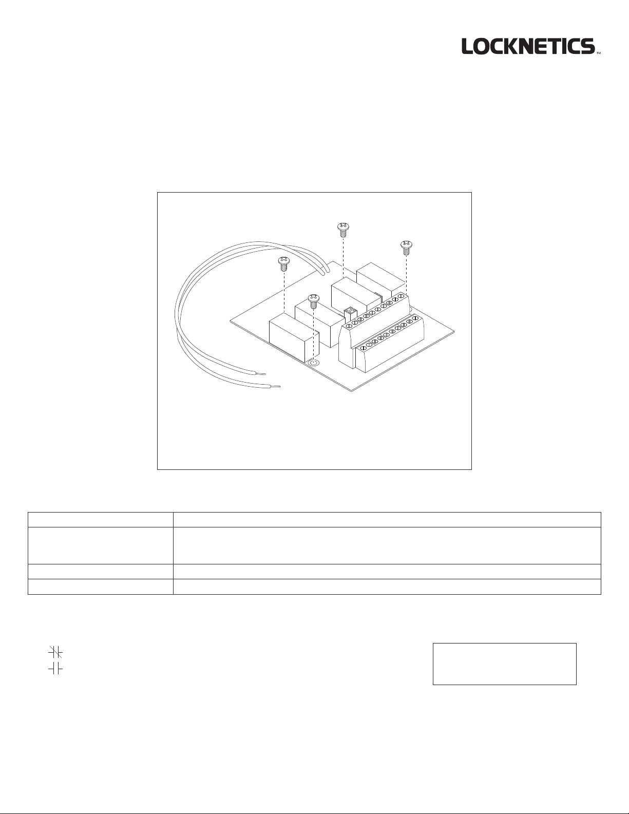
1 RDB4 Installation
Enclosure cutaway
shown for clarity
PS board
(already
installed)
WARNING
To avoid risk of electric shock, turn off AC power to power
supply before installing or wiring option board.
Mounted
in upright
position
Interior of
enclosure
2 RDB4 - Features and Operation
OUTPUT JUMPER
90°
SC to I: open
SC to I: closed
SC to I: open
SC to I: closed
Powered
Each
input
1-4
Contact
(default)
Dry
Contact
(optional)
control
Notes:
1. When SC to I is closed, the corresponding red LED for that output
will turn on.
2. When jumper is set to powered contact, the C terminal always has
DC Out voltage on it.
Jumpers
factory
installed
Jumper
rotated
6-32 x 1/4" (4)
INPUT OUTPUT
NC to GND: DC+ out
NO to GND: 0V
NC to GND: 0V
NO to GND: DC+ out
NC to C: Closed
NO to C: Open
NC to C: Open
NO to C: Closed
Output LED’s and Output Jumpers
1 23 4
SC GNDI1 NO1 C1 NC1 I2 NO2 C2 NC2
SC GNDI3 NO3 C3 NC3 I4 NO4 C4 NC4
RDB4
2
Page 3

3 Typical Wiring (see pages 4-6)
Wiring methods shall be applied in accordance with the National Electric Code/NFPA 70/NFPA 72/ANSI, and with all local codes and
authorities having jurisdiction.
WARNING
To avoid risk of electric shock, turn off AC power before
installing or servicing LP150/LP250 power supply.
3
Page 4

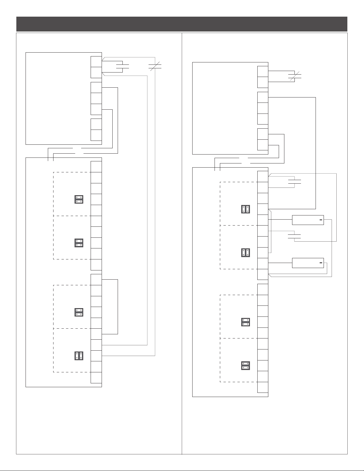
FS & FSE device connected to RDB4
2. Each output is controlled by its own individual ACC.
FS & FSE device connected to RDB4
Typical Wiring - FS & FSE
with FACP override (power cut off)
IN
OUT
DC
OUT
IN
C
NC
NO
DC-
DC+
DC-
SC
I1
NO1
C1
NC1
I2
NO2
C2
NC2
GND
SC
I3
NO3
C3
NC3
I4
NO4
C4
NC4
GND
+
+
CONTROL
LP250
CONTROL
BLK
RED
ZONE
1
ZONE
2
RDB4
ZONE
3
ZONE
4
FACP
ACC
FSE
ELECTRIC
STRIKE
ACC
MAGLOCK
FS
LP250
RDB4
without FACP connection
DC
IN
IN
C
NC
NO
DC-
DC+
DC-
SC
I1
NO1
C1
NC1
I2
NO2
C2
NC2
GND
SC
I3
NO3
C3
NC3
I4
NO4
C4
NC4
GND
ACC
+
ACC
+
CONTROL
CONTROL
OUT
OUT
BLK
RED
ZONE
1
ZONE
2
ZONE
3
ZONE
4
FSE
ELECTRIC
STRIKE
FS
MAGLOCK
Operation:
1. All power to RDB4 NC/NO outputs is completely cut off when FACP contacts
open. Any devices connected to them will return to their unpowered state.
4
Operation:
1. All outputs on the RDB4 are powered and controlled by their individual ACC
contacts.
2. The FACP contacts are not connected.
Page 5
FACP
Output 4 is used for FACP manual reset. Outputs 1-3 are available for lock control
before power can be applied to the RDB4 board. Once power is applied, the RDB4
RESET contacts again.
Outputs 1 and 2 have FACP override and will completely lose power when FACP
Typical Wiring - FACP
FACP with RDB4 Manual Reset
LP250
RDB4
ZONE
1
ZONE
2
ZONE
3
ZONE
4
CONTROL
IN
CONTROL
OUT
DC
OUT
BLK
RED
DRY
IN
C
NC
NO
DC-
DC+
DC-
SC
I1
NO1
C1
NC1
I2
NO2
C2
NC2
GND
SC
I3
NO3
C3
NC3
I4
NO4
C4
NC4
GND
FA
RESET
FACP controlling individual
zones on RDB4
DC
IN
IN
C
NC
NO
DC-
DC+
DC-
SC
I1
NO1
C1
NC1
I2
NO2
C2
NC2
GND
SC
I3
NO3
C3
NC3
I4
NO4
C4
NC4
GND
LP250
RDB4
CONTROL
CONTROL
OUT
OUT
BLK
RED
ZONE
1
DRY
ZONE
2
DRY
ZONE
3
ZONE
4
FACP
ACC
MAGLOCK
+
ACC
MAGLOCK
+
Operation:
1.
functions.
2. FA RESET contacts must be momentarily closed (and FACP contacts closed)
will function normally. Opening the FACP contacts will disconnect power from the
RDB4 board completely. Closure of the FACP contacts will not reapply power to
the RDB4. To reapply power for normal operation, momentarily close the FA
Operation:
1.
contacts are open. Outputs 3 and 4 have normal function and will not change if
FACP contacts are open.
5
Page 6

Blank Wiring Diagram
Blank diagram
for customer use
LP250
ZONE
1
ZONE
2
CONTROL
IN
CONTROL
OUT
DC
OUT
BLK
RED
IN
C
NC
NO
DC-
DC+
DC-
SC
I1
NO1
C1
NC1
I2
NO2
C2
NC2
GND
RDB4
SC
I3
ZONE
3
ZONE
4
NO3
C3
NC3
I4
NO4
C4
NC4
GND
6
Page 7

4 Wire run lengths
• Use the following table to estimate the gauge of wire required for the application.
• Wire length based on 15% voltage drop at 12 or 24V using stranded copper wire.
• The wire gauge listed is a minimum. The gauge can be increased if desired.
• Distance = total one way wiring distance between power supply and powered device (includes both power wires).
• For UL installations, the minimum permissible wire size to be used shall not be less than 22AWG.
WARNING
Keep power-limited wiring separate from non power-limited wiring.
When installing, route field wiring away from sharp projections, corners, and
Minimum 1/4" spacing must be provided.
CAUTION
internal components. Deburr all conduit fittings.
DISTANCE
(FEET)
100
200
300
400
500
22
22
20
20
18
0.2
22
18
16
16
14
0.5
18
16
14
14
12
1.0
16
14
12
1.5
LOAD CURRENT AT 12V
(AMPS)
WIRE GAUGE (AWG)
14
12
2.5
22
22
22
22
22
0.2
22
22
20
18
18
0.5
22
18
16
16
14
1.0
20
16
14
14
12
1.5
LOAD CURRENT AT 24V
(AMPS)
18
14
12
12
2.5
7
Page 8

5 Maintenance
Unit should be tested at least once a year for proper operation as follows:
Voltage Output:
• Verify the proper DC output voltage by measuring the DC+ and DC- terminals.
Fire Alarm Release (if used):
• Verify proper operation by opening the wiring to the CONTROL IN input. Conrm that all locks on outputs controlled by the
CONTROL OUT unlock properly.
6 Troubleshooting
Refer to Section 2 for LED status of outputs and jumper settings to determine the cause for any abnormal condition. Each LED has the
denition of its ON or OFF state.
7 Warnings and Cautions
Warnings look like this:
Cautions look like this:
Notices look like this:
Directions look like this:
WARNING
Warnings indicate potentially hazardous conditions, which if not
avoided or corrected, may cause death or serious injury.
CAUTION
Cautions indicate potentially hazardous conditions, which if
not avoided or corrected, may cause minor or moderate injury.
Cautions may also warn against unsafe practices.
Notices indicate a condition that may cause
equipment or property damage only.
Directions identify a step that may or may not
apply to your product configuration. It also may
direct you to another part of the instruction.
8
Page 9

pour verrouiller)
RDB4
Tableau d’options
La carte optionnelle RDB4 doit être utilisée avec l’alimentation LP250 lorsque des fonctionnalités supplémentaires sont requises. Ces
fonctionnalités incluent une distribution de 4 sorties contrôlables. Chaque sortie peut être congurée individuellement en tant que sorties
NO / NC alimentées ou sorties NO / NC sèches (isolées).
Instructions d’installation
Ces instructions couvrent :
RDB4
Carte RDB4 + vis de fixation (4)
Spécications RDB4:
Entrées I1 - I4 Contacts secs requis (fermé = actif), tension nominale de 12/24 VDC, 10 mA
Sorties O1 - O4 Réglage du cavalier alimenté: 12/24 VDC, 2.5A
Réglage du cavalier sec: Contacts de forme C 30 VDC, 2,5 A, NO / NC
11,7 - 12 V (13,2V nominal) ou 23,4 - 24 V (26,4V nominal)
Environnement 32 ° - 120 ° F (0 ° - 49 ° C), humidité relative jusqu’à 85%, utilisation à l’intérieur uniquement, zone
protégée
Conformité UL294, CSA22.2 NO. 205, CSFM, FCC
Dénitions :
Contacts normalement fermés (NC)
Contacts normalement ouverts (NO)
FSE - Sécurité intégrée (besoin d'alimentation
pour déverrouiller)
FACP - Panneau de contrôle d'alarme
incendie
ACC - Contacts de contrôle d'accès
FS - Sûreté intégrée (besoin d'alimentation
Voir la section 7 pour
une explication des
avertissements et mises
en garde utilisés dans
cette brochure.
9
Page 10

1 Installation du RDB4
Vue en coupe du
boîtier pour plus de
clarté
Carte PS
(déjà
installée)
Intérieur de
ATTENTION
Pour éviter tout risque d'électrocution, coupez l'alimentation
électrique avant d'installer ou de câbler la carte optionnelle.
Installez
en position
verticale
l'enceinte
6-32 x 1/4 po (4)
10
Page 11

2 RDB4 - Caractéristiques et fonctionnement
LED de sortie et cavaliers de sortie
1 23 4
SC GNDI1 NO1 C1 NC1 I2 NO2 C2 NC2
SC GNDI3 NO3 C3 NC3 I4 NO4 C4 NC4
RDB4
BORNE DE SORTIE
Chaque
entrée de
contrôle
Contact
motorisé
(par défaut)
1-4
Contact
sec
(optionnel)
Remarques:
1. Lorsque SC to I est fermé, le voyant rouge correspondant à cette
sortie s’allume.
2. Lorsque le cavalier est réglé sur le contact alimenté, la borne C a
toujours une tension de sortie CC.
Cavaliers
installés
en usine
Cavalier
tourné à
90 °
Normalement fermé à C : ouvert
Normalement ouvert à C : fermé
Normalement fermé à C : ouvert
Normalement ouvert à C : fermé
ENTRÉE SORTIE
NC à GND: DC + sortie
NON à la mise à la terre: 0V
NC à GND: 0V
NO À CC : CC + sortie
Normalement ouvert à C : fermé
Normalement ouvert à C : ouvert
Normalement fermé à C : ouvert
Normalement ouvert à C : fermé
3 Câblage typique (voir pages 12-14)
Les méthodes de câblage doivent être appliquées conformément au Code Électrique National//NFPA 70/NFPA 72/ANSI, ainsi qu’aux
codes et autorités locales compétents.
ATTENTION
Pour éviter tout risque de décharge électrique, mettez l’appareil hors
tension avant d’installer ou de réparer l’alimentation LP150/LP250.
11
Page 12

Câblage typique - FS & FSE
Dispositif FS & FSE connecté au RDB4
avec neutralisation FACP
(coupure de courant)
CC
IN
C
NC
NO
DC-
DC+
DC-
SC
I1
NO1
C1
NC1
I2
NO2
C2
NC2
GND
SC
I3
NO3
C3
NC3
I4
NO4
C4
NC4
GND
FACP
ACC
GÂCHE
+
ÉLECTRIQUE
FSE
ACC
+
FS
MAGLOCK
LP250
RDB4
ENTRÉE DES
CONTRÔLES
SORTIE DES
CONTRÔLES
SORTIE
NOIR
ROUGE
ZONE
1
ZONE
2
ZONE
3
ZONE
4
Dispositif FS & FSE connecté au
RDB4 sans connexion FACP
CC
IN
C
NC
NO
DC-
DC+
DC-
SC
I1
NO1
C1
NC1
I2
NO2
C2
NC2
GND
SC
I3
NO3
C3
NC3
I4
NO4
C4
NC4
GND
ACC
+
ÉLECTRIQUE
ACC
+
MAGLOCK
LP250
RDB4
ENTRÉE DES
CONTRÔLES
SORTIE DES
CONTRÔLES
SORTIE
NOIR
ROUGE
ZONE
1
ZONE
2
ZONE
3
ZONE
4
GÂCHE
FSE
FS
Opération :
1. Toute alimentation à sorties RDB4 NC/NO est complètement coupée lorsque
FACP est ouvert. Tous les périphériques qui y sont connectés reviendront à leur
état non alimenté.
2. Chaque sortie est contrôlée par son propre ACC individuel.
12
Opération :
1. Toutes les sorties du RDB4 sont alimentées et contrôlées par leurs contacts ACC
individuels.
2. Les contacts FACP ne sont pas connectés.
Page 13

La sortie 4 est utilisée pour la réinitialisation manuelle FACP. Les sorties 1 à 3 sont
coupera complètement l’alimentation de la carte RDB4. La fermeture des contacts
Câblage typique - FACP
FACP avec réinitialisation
manuelle RDB4
CC
IN
C
NC
NO
DC-
DC+
DC-
SC
I1
NO1
C1
NC1
I2
NO2
C2
NC2
GND
LP250
ENTRÉE DES
CONTRÔLES
SORTIE DES
CONTRÔLES
SORTIE
NOIR
ROUGE
ZONE
1
ZONE
2
RDB4
SC
I3
SEC
NO3
C3
NC3
I4
NO4
C4
NC4
GND
ZONE
3
ZONE
4
CONTACT
Opération :
1.
disponibles pour les fonctions de contrôle de verrouillage.
2. Les contacts FA RESET doivent être momentanément fermés (et les contacts
FACP fermés) avant de pouvoir alimenter la carte RDB4. Une fois que le courant
est appliqué, le RDB4 fonctionnera normalement. L’ouverture des contacts FACP
FACP ne redonnera pas d’alimentation au RDB4. Pour rétablir le courant en
fonctionnement normal, fermez momentanément les contacts FA RESET.
FA
RESET
FACP
FACP contrôlant des zones
individuelles sur RDB4
CC
IN
C
NC
NO
DC-
DC+
DC-
SC
I1
NO1
C1
NC1
I2
NO2
C2
NC2
GND
SC
I3
NO3
C3
NC3
I4
NO4
C4
NC4
GND
FACP
ACC
MAGLOCK
+
ACC
MAGLOCK
+
ENTRÉE DES
CONTRÔLES
ZONE
1
ZONE
2
SORTIE DES
CONTRÔLES
SORTIE
NOIR
ROUGE
CONTACT
SEC
CONTACT
SEC
LP250
RDB4
ZONE
3
ZONE
4
Opération :
1. Les sorties 1 et 2 ont la priorité FACP et perdront complètement l’alimentation
lorsque les contacts FACP sont ouverts. Les sorties 3 et 4 ont une fonction
normale et ne changeront pas si les contacts FACP sont ouverts.
13
Page 14

Schéma de câblage vierge
Diagramme vierge à
l'usage du client
LP250
ZONE
1
ZONE
2
ENTRÉE DES
CONTRÔLES
SORTIE DES
CONTRÔLES
SORTIE
CC
NOIR
ROUGE
IN
C
NC
NO
DC-
DC+
DC-
SC
I1
NO1
C1
NC1
I2
NO2
C2
14
RDB4
ZONE
3
ZONE
4
NC2
GND
SC
I3
NO3
C3
NC3
I4
NO4
C4
NC4
GND
Page 15

4 Longueurs de l
• Utilisez le tableau suivant pour estimer le calibre de l requis pour l’application.
• Longueur de l basée sur une chute de tension de 15 % à 12 ou 24 V avec un l de cuivre toronné.
• Le calibre de l indiqué est un minimum. La jauge peut être augmentée si vous le souhaitez.
• Distance = distance totale de câblage unidirectionnel entre l’alimentation et le périphérique alimenté (inclut les deux câbles
d’alimentation).
• Pour les installations UL, la taille de câble minimum permis à utiliser ne doit pas être inférieure à 22 AWG.
ATTENTION
Gardez le câblage limité en puissance séparé du câblage non limité en
puissance. Un espacement minimum de 1/4 po doit être fourni.
MISE EN GARDE
Lors de l'installation, éloignez le câblage des projections, des angles et des
composants internes pointus. Ebavurer tous les raccords de conduit.
DISTANCE
(PIEDS)
100
200
300
400
500
22
22
20
20
18
0.2
22
18
16
16
14
0.5
18
16
14
14
12
1.0
COURANT DE CHARGE À 12V
(AMPÈRES)
JAUGE DE FIL (AWG)
16
14
12
1.5
14
12
2.5
22
22
22
22
22
0.2
22
22
20
18
18
0.5
22
18
16
16
14
1.0
COURANT DE CHARGE À 24V
(AMPÈRES)
20
16
14
14
12
1.5
18
14
12
12
2.5
15
Page 16

5 Entretien
L’unité doit être testée au moins une fois par an pour vérier son bon fonctionnement, comme suit:
Tension de sortie:
• Vériez la tension de sortie CC appropriée en mesurant les bornes DC + et DC-.
Déclenchement d’alarme incendie (si utilisé):
• Vériez le bon fonctionnement en ouvrant le câblage de l’entrée CONTROL IN. Vériez que tous les verrouillages sur les
sorties contrôlées par CONTROL OUT sont correctement déverrouillés.
6 Dépannage
Reportez-vous à la section 2 pour connaître l’état des voyants des sorties et des cavaliers an de déterminer la cause de toute condition
anormale. Chaque LED a la dénition de son état ON ou OFF.
7 Avertissements et mises en garde
Les avertissements
ressemblent à ceci :
Les mises en garde
ressemblent à ceci :
Les avis ressemblent
à ceci :
Les instructions
ressemblent à ceci :
AVERTISSEMENT
Les avertissements indiquent des conditions potentiellement
dangereuses qui, si elles ne sont pas évitées ou corrigées, peuvent
provoquer des blessures graves, voire mortelles.
MISE EN GARDE
Les mises en garde indiquent des conditions potentiellement
dangereuses qui, si elles ne sont pas évitées ou corrigées,
peuvent causer des blessures mineures ou modérées. Les
mises en garde peuvent également mettre en garde contre les
pratiques dangereuses.
Les avis indiquent une condition pouvant
uniquement causer des dommages
matériels.
Les instructions identifient une étape qui peut
ou non s'appliquer à la configuration de votre
produit. Cela peut également vous diriger vers
une autre partie de l'instruction.
16
Customer Service
1-877-671-7011 www.allegion.com/us
Canada
1-800-900-4734 www.allegion.ca
© Allegion 2019
Printed in Taiwan
829768-00 Rev. 06/19-b
 Loading...