

Page 1
RC Pure IP
TM
multi-technology
reader controller
User guide
Page 2

FCC Statement
Model FCC ID IC ID
RC11
RC15
RCK15
This device complies with Part 15 of the FCC Rules.
Operation is subject to the following two conditions:
(1) This device may not cause harmful interference, and
(2) This device must accept any interference received, including interference that may cause
undesired operation.
Changes or modifications not expressly approved by the party responsible for compliance could void
the user’s authority to operate the equipment.
This equipment has been tested and found to comply with the limits for a Class B digital device,
pursuant to part 15 of the FCC Rules. These limits are designed to provide reasonable protection
against harmful interference in a residential installation. This equipment generates, uses, and can
radiate radio frequency energy and, if not installed and used in accordance with the instructions, may
cause harmful interference to radio communications. However, there is no guarantee that interference
will not occur in a particular installation. If this equipment does cause harmful interference to radio or
television reception, which can be determined by turning the equipment off and on, the user is
encouraged to try to correct the interference by one or more of the following measures:
(1) Reorient or relocate the receiving antenna.
(2) Increase the separation between the equipment and receiver.
(3) Connect the equipment to an outlet on a circuit different from that to which the receiver is
connected.
(4) Consult the dealer or an experienced radio/TV technician for help.
XPB-RC11 8053B-RC11
XPB-RC15 8053B-RC15
This device complies with RSS-210 of Industry Canada.
Operation is subject to the following two conditions:
(1) This device may not cause harmful interference, and
(2) This device must accept any interference received, including interference that may cause
undesired operation.
Le présent appareil est conforme aux CNR d’Industrie Canada applicables aux appareils radio
exempts de licence.L’exploitation est autorisée aux deux conditions suivantes:
(1) l’appareil ne doit pas produire de brouillage, et
(2) l’utilisateur de l’appareil doit accepter tout brouillage radioélectrique subi, même si le
brouillage est susceptible d’en compromettre le fonctionnement.
This Class B digital apparatus complies with Canadian ICES-003.
Cet appareil numérique de la classe B est conforme à la norme NMB-003 du Canada.
For RF Safety and per FCC and Industry Canada regulations, the product should never be
installed within 8-inches (20cm) of typical people locations.
U.S. Patent Nos.
7,775,429
8,662,386
9,153,083
9,336,633
7,676,839
U.S. Application No.
14/019,924
Page 3

Contents
ii FCC Statement
iv Contact information
iv Warnings and cautions
5 Before you begin
5 General requirements
6 Reader controller specifications
7 Installation location guidelines
9 Reader controller reset button
10 Wiring
10 Powering the reader controllers
11 Door wiring
13 Lock wiring using PoE
13 Door sensor wiring
14 Advanced Security Module (ASM) wiring
15 Configuring communications
15 Reader controllers to host soware
16 Appendix A: Power options
16 PoE Power Budget Calculations
17 Additional power options
18 Dual power sources
19 Appendix B: Additional wiring considerations
19 ASM LED status index
19 Wiring two readers to one lock
20 Managing inductive load challenges
21 PoE: Magnetic lock, ASM and PIR
22 Appendix C: UL Disclaimers
iii • Schlage • Reader controller
Page 4
Contact information
If you need assistance, contact technical support at:
1-877-671-7011
www.allegion.com/us
MIFARE® and DESFire™ are registered trademarks of NXP B.V.
Warnings and cautions
WARNING
Warnings indicate potentially hazardous conditions,
which if not avoided or corrected, may cause death or
Cautions indicate potentially hazardous conditions,
which if not avoided or corrected, may cause minor or
moderate injury. Cautions may also warn against
Notices indicate a condition that may cause equipment
serious injury.
CAUTION
unsafe practices.
NOTICE
or property damage only.
iv • Schlage • Reader controller
Page 5

Before you begin
This guide discusses each wiring process separately. Understanding all of these processes makes a project much simpler and
helps guarantee success. To install a Reader Controller unit, you must complete four key tasks:
1. Mount the Reader Controller in the appropriate location. Recommended locations and wiring methods shall be in
accordance with 1) the National Electrical Code, {ANSI/NFPA 70}; 2) International Building Code {IBC}, and 3) Americans
with Disabilities Act {ADA}.
2. Supply power to the Reader Controller. This may be accomplished with power being provided on the Ethernet data cable
(Power over Ethernet [PoE / PoE+ / IEEE 802.3af]) or through an external DC power source (12VDC). When powering from
PoE or PoE+, in order for the system to be UL294 V7 compliant, the Power Sourcing Equipment (PSE) injector or end point
must be compliant to UL294 or UL294B standards.
3. Wire the unit to the door’s locks and other components for physical access control.
4. Connect the unit to the data network for communication with the host access control system.
The Reader Controller complies with UL 294 V6 and is rated for the following performance levels:
Standby power Level I
Endurance Level IV
Line Security Level I
Destructive Attack Level I (ASM required)
General requirements
• If PoE is not being used, then use only UL-listed, access control, power-limited power supplies with an ‘AC on’ indicator light
clearly visible on the enclosure. Power supplies should provide at least four hours of standby power.
• Never connect power supplies to a switch-controlled receptacle.
• Install the Schlage system in accordance with the National Electrical Code NFPA 70, IBC, and ADA requirements, or the
Canadian Electrical Code, C22.1-02. (Local authority has jurisdiction.)
• Use only UL-listed wire or cabling recognized suitable for Schlage power supply and data communications, in accordance
with the National Electrical Code.
• Where possible, separate Schlage equipment and cabling from sources of electromagnetic interference (EMI). Where this is
not possible, take other steps to reduce the effect of EMI on cabling or equipment.
• Protect input and output terminals adequately from transient signals. Also, connect these terminals to power-limited
circuitry.
• The readers are UL Listed for standalone operation only. Reference to operation with the server have not been investigated
by UL.
• Operation with the ASM has not been investigated by UL.
• Accessories connected to the readers shall be UL Listed.
• The reader controllers are intended to be used with the building’s communication system and not intended for direct
outside connection.
• All input/output wiring shall employ earth grounded shielded cable. The maximum wiring distance is 30 m, same room.
• The minimum conductor gauge permitted to connect between the PSE or power injector and the device shall be 26 AWG
(0.13 mm2) for patch cords; 24 AWG (0.21 mm2) for horizontal or riser cable.
• Premise network equipment shall be UL Listed for compliance with UL60950-1 or UL62368-1.
• Intended for Alternative A PoE sources. NEC, Class 3 wiring methods shall be followed.
• Compliance to ULC-S319, Electronic Access Control Systems, would be invalidated through the use of any add-on,
expansion, memory or other module manufactured or supplied by the manufacturer or manufacturer’s representative.
• In POE applications, installation shall be in accordance with Article 725.121, Power Sources for Class 2 and Class 3 circuits.
5 • Schlage • Reader controller
Page 6

Before you begin | Reader controller specifications
Reader controller specifications
Model RC11 RC15 RCK15
Reader controller Type Mobile enabled multi-technology Mobile enabled multi-tech w/keypad
Mounting Style Mullion Single Gang
Standards ISO 14443A, ISO 15693
Certifications FCC Certification, IC Certification, UL 294/cUL Listed, RED Directive, CE Mark, IP65, REACH,
Frequency 2.4 GHz, 13.56 MHz and 125 kHz
Technology Supported (See Appendix C: UL Disclaimers on page 22.)
CSN
Proximity
Smart
Mobile (NFC)
Mobile (Bluetooth)
Read Range
Prox FSK
Prox ASK
MIFARE Classic EV1
MIFARE Plus
MIFARE DESFire EV1
MIFARE DESFire EV2
Schlage Mobile Credential
(Bluetooth) (short range-standard)
Schlage Mobile Credential
(Bluetooth) (long range-optional)
Users 64,000
Audits 5,000
Schedules 32
Holidays 32
Auto Events 448
Communication Standards 10/100 Mbps, Half or Full Duplex
Power Options Power Over Ethernet (PoE/PoE+), (IEEE 802.3af/at)
Outputs Locking mechanism: 600 mA @ 12VDC max
Signal Inputs Door Position Switch (DPS)
Operating Temperature -31°F (-40°C) to 151°F (66°C)
Dimensions 5.94” x 1.77” x 1”
Bluetooth SIG, RoHS3
Up to 1.75" (4.4 cm) Up to 4.0" (10.1 cm) Up to 4.0" (10.1 cm)
Up to 1.5" (3.8 cm) Up to 3.25" (8.2 cm) Up to 3.25" (8.2 cm)
Up to 1.75" (4.4 cm) Up to 2.0" (5.1 cm) Up to 2.0" (5.1 cm)
Up to 0.25" (0.6 cm) Up to 1.25" (3.2 cm) Up to 1.25" (3.2 cm)
Up to 0.5" (1.3 cm) Up to 1.5" (3.8 cm) Up to 1.5" (3.8 cm)
Up to 1.5" (3.8 cm) Up to 2.0" (5.1 cm) Up to 2.0" (5.1 cm)
5’ (1.5 m)
30’ (9.1 m)
Ethernet, WebSockets, Standard Cat5e or better Cable
DHCP Addressing Supported
Transport Layer Security (TLS) version 1.2
Advanced Encryption Standard (AES), 256-bit
DC Power: 12VDC +/- 10% at 300 mA
Î PLEASE NOTE: 300 mA current rating does not include locking mechanism
current. Consult your product documentation.
Advanced Security Module Outputs
RS-485 (future use)
2x General Purpose Outputs (TTL logic levels at ± 24mA)
Request to Exit (REX)
Auxiliary Input (AUX)
5.13” x 3.25” x 1” (130 x 83 x 25 mm)
(150 x 45 x 25 mm)
6 • Schlage • Reader controller
Page 7
Before you begin | Installation location guidelines
Installation location guidelines
When selecting the location where you are going to mount the Reader Controller, a few guidelines should be observed.
1. In humid environments, a drip-loop should be formed in the Reader Controller’s cables, before the cables enter the unit.
2. The Reader Controller should be protected from extreme heat and sunlight. It is rated for conditions up to 151 F. A direct
southern exposure, in the Southwest area of the United States may exceed these ratings.
3. The cables extending from the back of the Reader Controller’s field wiring cable is available in a two standard lengths (10'
or 25' [3 m or 7.62 m]). The door wiring must terminate within that distance or less than 98' (30m) from the Reader
Controller.
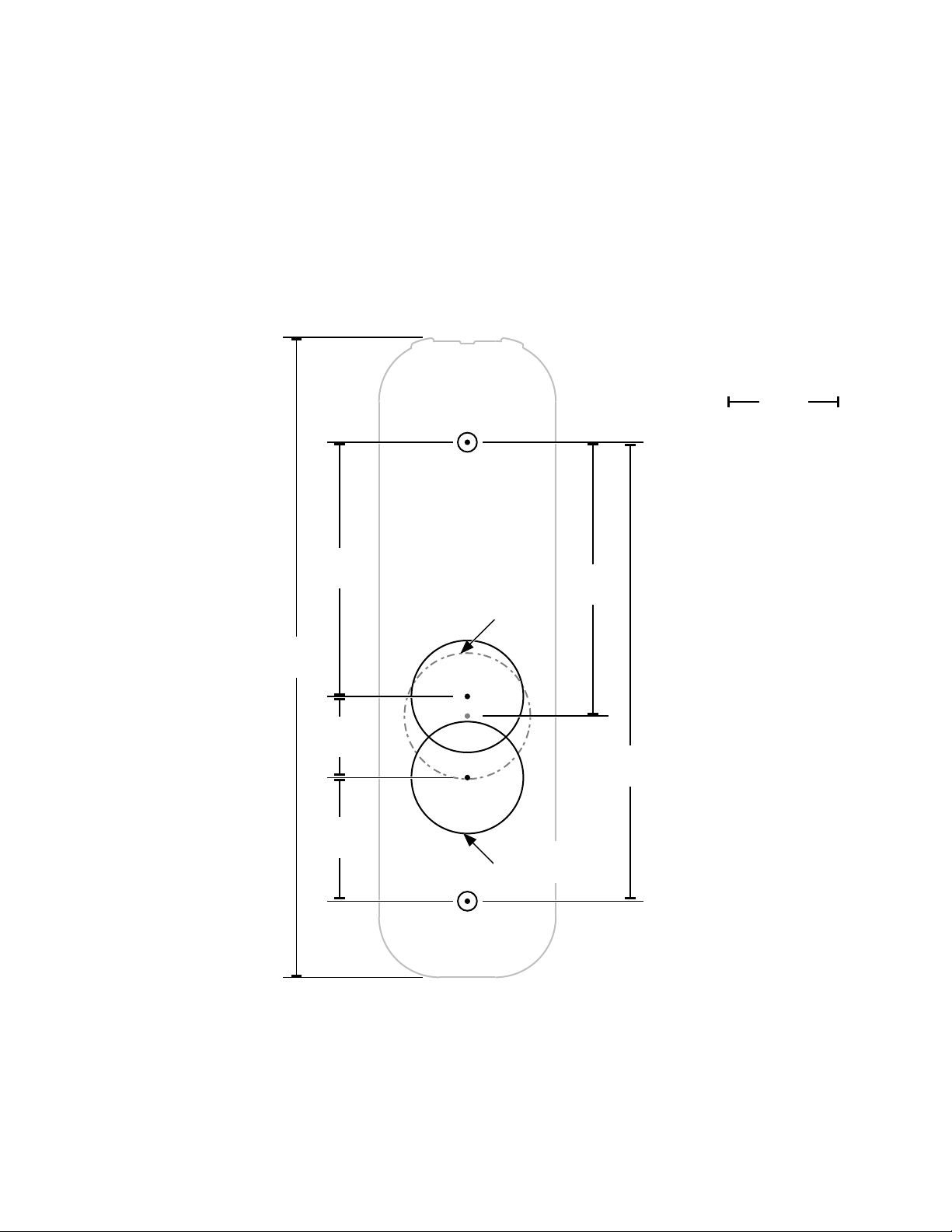
4. The wall mounting templates are shown in Figure 1.1: RC11 Mounting and Figure 1.2: RC15/RCK15 Mounting.
5. The selected location should meet ADA requirements. Check local regulations for more information.
Template to scale. Check
scaling when printing.
1"
(25.4)
Figure 1.1: RC11 Mounting
5 ²³"
(145.256)
2 "
(40.481)
²³"
(18.415)
1 ³"
(27.940)
Alternate hole
1 ¹" (28.575)
1" (25.400)
2 places
2 "
(62.128)
4 ³"
(101.600)
mm in
parenthesis
7 • Schlage • Reader controller
Page 8

Before you begin | Installation location guidelines
Template to scale. Check
scaling when printing.
1"
(25.4)
1 "
(39.688)
²²"
(19.05)
4 "
(125.412)
Figure 1.2: RC15/RCK15 Mounting
Alternate hole
1 ¹" (28.575)
1" (25.400)
2 places
1 ³"
(44.450)
3 "
(82.550)
mm in
parenthesis
8 • Schlage • Reader controller
Page 9

Before you begin | Reader controller reset button
Reader controller reset button
The reset button is located on the back of the Reader
Controller. It can be used for two different types of
resets.
Î The Reader Controller must be connected to the
network before initiating reset.
Network reset
Press and hold the reset button until one green LED
flash and one short beep, (approx. five secs.) then
release. Successful network reset is indicated by one
LED flash and one short beep. A network reset
reestablishes the network connection using the current
network settings. The certificate file and domain
routing information is reestablished prior to reforming
the connection to the host access control system.
reset button
Figure 1.3: Reset button locations
Table 1.1: Reader reset indications
Factory default reset
Press and hold the reset button until two green LED
flashes and two beeps (approx. 10 secs.), then release.
Successful factory default reset is indicated by a long
steady green light and long beep. A Factory Default
Reset (FDR) will return the Reader Controller settings
to the original settings as shipped from the factory.
Removes configurations, databases, and requires the
lock to be re-captured. A FDR will not remove the device from your ENGAGE account.
Actions Lights Beeps
Factory Default Reset (FDR) initiated 2x green short 2x short
Network reset initiated 1x green short 1x short
Reset complete 1x green long 1x long
Reset failed 2x red long 2x long
9 • Schlage • Reader controller
Page 10

Wiring
Powering the reader controllers
• A direct connection to a power source is required.
• Reader controllers can be powered with 12 volts DC or PoE (IEEE 802.3af) power and the supply must be regulated.
NOTICE
Never connect 24VDC to the Reader Controller. 24V will
damage the device and will void the unit’s warranty.
Power over ethernet (PoE) option
PoE allows one cable to supply data and
power to the Reader Controller, which in
turn can then supply 12VDC to the door’s
electronic lock.
If your network switches do not support
PoE, then a PoE Injector can be used to
augment the switch’s output with PoE
power. A PoE injector is normally located
close to your existing network hub/
switch, and the PoE Injector itself is
plugged directly into a standard AC
outlet, or for extra reliability, a UPS with
battery backup.
A standard CAT5/6 cable is then run
between the PoE source (Injector or
switch) and the Reader Controller which
will be located right next to the door. The
CAT5/6 cable can be up to 100 Meters
(328 feet) long, including all patch cables
and patch panels.
Host server
IP network
data
PoE network
switch
Reader Controller
data &
PoE
ASM
latch
Supplying 12 VDC to door
components from the PoE
powered Reader Controller
When the Reader Controller is powered
by PoE, the reader can supply 0.6 amps
@12 VDC power for external components.
This DC power is available via two field
wiring wires.
The red field wiring is typically used to control the door’s lock. The red wire’s 12VDC output will be activated/deactivated when
the reader is operating the door’s lock. This connection has a built-in current limiting feature to prevent the lock from consuming
too much power.
The orange field wiring provides a source of continuously-available 12VDC power for other desired devices.
10 • Schlage • Reader controller
Figure 2.1: Overview of how to use
PoE to power both the Reader
Controller and an electronic
locking mechanism
Page 11

Wiring | Door wiring
Door wiring
Î Door wiring should be done before power is connected to every Reader Controller.
Example devices:
• Electronic door latch
• Request to exit (REX) devices like a REX button or motion detector
• Door sensors
• Figure 2.2: Typical configuration of equipment at the door
Reader controller control-leads
Field wiring consists of 12 wire leads (22AWG) which are used to connect to the various components at the door location. Most
installations do not require the use of all the leads. The usage of each available lead is shown in Figure 2.3: Reader controller
field wiring color codes.
The controllers have a lock-control circuit. This circuit provides conditioned 12VDC power up to 600mA and can be directly
connected to the electronic lock to unlock the door when a valid credential is presented.
The usage of each lead will be detailed in the next few pages.
Î Field wiring cable length must remain under 98' (30 m).
door
sensor
Lock Relay
DPS
REX
REX
button
reader/
controller
latch
Figure 2.2: Typical configuration of equipment at the door
RS-485 A
RS-485 B
V-Line-P
AUX Input
ASM C
Reader controller
ASM D
TTL1
TTL2
Ground
Figure 2.3: Reader controller field wiring color codes
11 • Schlage • Reader controller
Page 12

Wiring | Door wiring
Table 2.1: Input/Output Descriptions
Name I/O Pin Wire Color Description
Lock Lock Relay Output 1 Red The dry lock relay is capable of switching up to 600 mA resistive
DPS Door Position
Switch
REX Request to Exit Input 3 Green When the switch activates, the RC will audit the event and activate
RS-485 A RS-485 Data A Both 4 Pink Future intent RS-485 Data A communication.
RS-485 B RS-485 Data B Both 5 Yellow/
V-Line-P 12V Input/Output Either 6 Orange 12 VDC input. When POE powered, 12 Vdc output at 100mA max.
AUX Auxiliary Input Input 7 Gray When the switch activates, the RC will audit the event and activate
ASM D Advanced Security
Module Data
ASM C Advanced Security
Module Clock
TTL1 Generic Logic
Output 1
TTL2 Generic Logic
Output 2
Ground Ground Ground 12 Black Electrical ground for the RC.
Input 2 Blue When a DPS is installed, the RC will trigger an alert, forced door or
Black
Output 8 Yellow Advanced Security Module data communications.*
Output 9 White Advanced Security Module clock communications.*
Output 10 Purple Generic output at TTL voltage levels. Capable of sinking or
Output 11 Brown Generic output at TTL voltage levels. Capable of sinking or
load at 12 VDC.
propped door, and can be configured to activate the TTL output(s).
the Lock Relay, and/or TTL(s) if configured. REX can be configured
active high or active low through configuration settings.
Future intent RS-485 Data B communication.
the Lock Relay, and/or TTL(s) if configured. AUX can be configured
active high or active low through configuration settings.
sourcing up to 24 mA. TTL can be configured to activate based on
various sources including the lock relay, REX, AUX, and DPS. TTL
can be configured active high or active low through configuration
settings.
sourcing up to 24 mA. TTL can be configured to activate based on
various sources including the lock relay, REX, AUX, and DPS. TTL
can be configured active high or active low through configuration
settings.
* Not investigated by UL.
12 • Schlage • Reader controller
Page 13

Wiring | Lock wiring using PoE
Lock wiring using PoE
The Reader Controller supports a simplified configuration when PoE is
being used to supply the lock’s power.
1. Connect the red wire on the Reader Controller to the positive lead
of the electric lock. See Figure 2.4: Typical fail-secure door lock
wiring
2. Connect the negative lead of the lock to the black wire on the
Reader Controller.
3. See Managing inductive load challenges on page 20 for more
info regarding the use of the BackEMF diode.
Door sensor wiring
Connecting the Reader Controller to a door sensor allows the host
access control system to detect if the door is ajar. Then the host access
control system can create alarms based on the door’s state.
First, connect one terminal of the door sensor to the reader's blue wire.
Then connect the door sensor's other terminal to the Reader
Controller's common ground wire (black).
BackEMF
Protection Diode
Figure 2.4: Typical fail-secure door lock wiring
Lock and strike
Door sensor
(normally closed)
Figure 2.5: Door sensor wiring
13 • Schlage • Reader controller
Page 14

Wiring | Advanced Security Module (ASM) wiring
Advanced Security Module (ASM) wiring
The Reader Controller has an optional ASM,
which allows you to isolate the door’s lock
control circuitry on the secure side of the
building.
The ASM contains a form-C relay with
dry-contacts that are rated for 3 amps of current
@ 30 Volts. It can also be used in cases where
the Reader Controller is switching an externally
supplied voltage or an external control signal.
Examples of such usages include operating a
24VDC lock, or switching a logic signal for a
garage door opener.
Two methods of connecting the ASM are shown.
Figure 2.6: ASM with Reader Controller
supplying PoE power shows powering both the
lock and the ASM with the Reader controller’s
PoE power. Figure 2.7: ASM with lock running
on 24V external power shows powering the
ASM with the Reader controller’s PoE power
output, and the lock with an external 24 volt
power supply.
Figure 2.6: ASM with Reader Controller supplying PoE power
BackEMF
Protection Diode
Jumper
ASM
Relay
+ 12V
Door lock
(fail secure)
ASM Wire Conductor Preparation:
Factory-installed jumer
has been removed
Strip back the wire insulation: 0.25" to 0.281" (6
mm to 7 mm).
Acceptable single conductor sizes: 26 gauge to
15 gauge
Acceptable two conductors sizes: 26 gauge to 15
gauge
ASM
Relay
Î Note for multi-stranded conductors: Avoid
allowing any stray wire strands from
contacting the adjacent terminal block
connection.
Twist the multi-strands together prior to
insertion. Lightly solder-tinning the exposed wire
can help prevent stray strands.
(fail secure)
Figure 2.7: ASM with lock running on 24V external power
Table 2.2: ASM wiring
Reader Side Connection Lock Side Connection
Label Wire Label PoE Power (Figure 2.6) 24V Power (Figure 2.7)
A
B
C
D
Orange (12 V input power)
Black (ground)
Yellow
White
1
2
3
4
5
12V output power not used (factory-installed jumper removed)
Power ground not used
ASM common contact
ASM normally closed (NC) contact (fail-safe lock)
ASM normally open (NO) contact (fail-secure lock)
Door lock
+
24 VDC
-
BackEMF
Protection Diode
14 • Schlage • Reader controller
Page 15

Configuring communications
The Reader Controller can communicate with a variety of access control soware platforms. Contact your sales associate for a
complete list. The reader controllers communicate over the network to the host system. Below are best practices on this
configuration.
Reader controllers to host soware
Î Many other Ethernet network topology permutations exist. This is the most common Ethernet configuration used by
Schlage customers.
This is the simplest type of network connection. The Reader Controller is an IOT-style device that requires minimal network
configuration to function. The physical access control partner’s host system provides a cloud instance of the host soware. The
reader controllers must be configured to connect to host soware. The ENGAGE Mobile Application provides the interface to
capture and commission a unit with the initial configurations required to connect to the host soware. The following
configurations are needed to direct the Reader Controller to connect to the host soware:
Î Notice: Prior to capturing and commissioning, the reader controlled must be fully installed in its intended location
(including cover).
• WebSocket Server URL
• Certificate Authority Server URL
Addressing: The recommended best-practices is to let the local network’s DHCP service assign the IP Address to each reader.
As an alternate, you can manually assign the reader’s IP Address. To allow the reader to successfully reach the host soware,
the following setting are required:
• Static IP Address that is valid on the local subnetwork
• IP Address of the local subnetwork’s gateway.
• Subnet Mask
• DNS server’s IP Address
• Alternate DNS server’s IP Address
Here are a couple guidelines to follow to assure that your network’s configuration will support the Schlage access system.
• The Reader Controller is a standard “network appliance.” Standard TCP/IP networking rules apply.
• DHCP Configuration
• If the reader controllers are to be le on DHCP it is strongly recommended to use reservations, so the IP address does
not need to be renewed.
• Network Configuration
• A common best-practice is to place the reader controllers in a dedicated subnet
• The PoE switch should have enough power to run all ports and account for in rush. (IE. A switch restart which would
cause all readers to restart.)
15 • Schlage • Reader controller
Page 16

Appendix A: Power options
PoE Power Budget Calculations
When planning an installation using PoE, you need to validate that the PoE source (PoE Injector or PoE equipped Network
Switch) supplying the PoE power is sized properly for all the attached PoE devices. To do this, you total up the power draw (in
watts) of the PoE connections, and compare that total power draw to the rated capacity of the PoE source.
When the Reader Controller is dual powered there may be an increased number of power audits. If the 12VDC regulated power
supply voltage fluctuates above 12.1VDC the Reader Controller will transition from the PoE source to the DC power supply,
resulting in an audit.
Likewise when the DC power supply drops below 12.1VDC the Reader Controller will transition from the DC power supply to the
PSE, resulting in another audit.
Table 4.1: Expected PoE power draws of the reader controllers
Door Location Configuration PoE Power Requirement *
Reader controller 2.65 W
Reader controller with Electronic Lock (300 mA @ 12V) 6.26 W
Reader controller with Electronic Lock (600 mA @ 12V) 9.85 W
* Ethernet cabling power losses not included. Losses range from being negligible for short Cat5/6
cables, up to about 16% for 100 meter Cat5/6 cables.
To meet the Reader Controller’s variable PoE power requirements, the Reader Controller will classify itself with the PoE source
as a “Class 0” PoE device. The power usage of a Class 0 device can range between 0.4 to 13.0 watts at the device (up to 15.4
watts from the PoE source).
Some network PoE equipment will budget and allocate it’s distribution of PoE power based upon the maximum power usage of
the each attached device’s classification. If your network equipment uses this power provisioning technique, then you should
budget 15.4 watts for each Reader Controller. Such network PoE Equipment may allow you to manually configure the amount of
power that should be allocated to each device. Configuring the PoE equipment for an allocation of 3.0 watts or 11.0 watts per
connection would be appropriate. When powering from PoE or PoE+, in order for the system to be UL294 V7 compliant, the PoE
injector or end point must be compliant to UL294 or UL294B standards.
Using PoE over longer cable distances:
The Reader Controller can be powered via PoE on cable runs up to 328' (100 m) long (the standard Ethernet cable limit).
For Reader Controller locations that have longer cable runs (> 164' [50 m]), extra care should be given to the planning and
installation of the network cabling. The PoE power delivery system will running at about 80% of the allowable capacity, when
powering a 600mA lock over a 100 meter cable run.
For these long cable run installations, here are some items to focus on:
• Cabling:
• Use high-quality Ethernet cabling (Cat 5e or Cat6). Please note that the power loss over a Cat 6 cable is about 30%
less than the power loss on a Cat5e cable
• Cable Length. The 100 meter limit needs to include any patch cords and patch panels.
• Follow IEEE/TIA installation best practices.
• PoE Source
• The PoE Source (PoE Network switch or PoE Injector) meets the IEEE 802.3af standard.
• The PoE Source is properly sized to supply 15.4 watts/port. (Cabling power loses can be up to 2.5 watts/cable)
16 • Schlage • Reader controller
Page 17

Appendix A: Power options | Additional power options
Additional power options
Most installations will use PoE for the Reader Controller and door locks to control a door using a single, standard network cable.
There are many additional options available if the door location requires more power than a standard PoE-powered Reader
Controller can provide.
The different options require different configurations of the supporting equipment and/or building wiring. Table 4.2: Power
option configurations and Figure 4.1: Power options describes some of these power options.
Table 4.2: Power option configurations
Power Source Switchable
PoE (802.3af) 0.60 amps
PoE (802.3af) 0.55 amps
DC Power Supply 12
VDC
PoE Plus (802.3at) 1.8 amps
High-Powered PoE
(non-standard)
Example: PoE
Injector PowerDsine
PD-9501G
Power
(Max)
(12VDC)
(12VDC)
3.0 amps
(12VDC)
(Approx)
(12VDC)
3.0 amps
(12VDC)
Equipment at the
Door
Reader controller Reader controller’s
Reader controller
ASM
Reader controller
ASM
Reader controller
ASM
PoE Splitter
Example: PoE
Splitter PowerDsine
PD-AS-701/12
Reader controller
ASM
PoE Splitter
Example: PoE
Splitter PowerDsine
PD-AS-951/12-24
Limiting Factor Dia.
available PoE
Output
Reader controller’s
available PoE
Output {minus} the
power required by
the ASM
Rating of ASM’s lock
relay (12VDC
required by ASM’s
internal circuitry)
Rating of PoE
Splitter {minus}
power required to
operate Reader
Controller & ASM
Rating of ASM’s lock
relay
Equipment closet
PoE switch
A
B
C
or injector
0.60 A
Door location
Equipment closet
D
E
PoE switch or
injector
A
B
ASM
Door location0.55 A
Equipment closet
Switch
DC power
supply
Figure 4.1: Power options
17 • Schlage • Reader controller
C
ASM
Door location3.00 A
Equipment closet
High-powered PoE
switch or injector
(IEEE 802.3at)
D
ASM
PoE
Splitter
Door location1.80 A
Equipment closet
Switch
Proprietary
PoE Injector
Proprietary
PoE Splitter
E
ASM
Door location3.00 A
Page 18

Appendix A: Power options | Dual power sources
Dual power sources
Typical Reader Controller install
with:
• Redundant power supplies
• Input power: PoE
• Input power: 12VDC
Solution highlights
• Improve the ACS fault-tolerance
design by supplying the Reader
Controller with electrical power
from two independent power
sources.
• With this design, if the Reader
Controller's connection to the
PoE nework switch is lost, the
Reader Controller will
automatically begin to draw its
power from the DC power
source.
Installation tips
• Schottky Diode:
• Manufacturer: Vishay/
General Semiconductor
• P/N: SB560-E3/54 or equivalent
• Install the BackEMF diode
• Red wire will provide the lock with +12VDC
Figure 4.2: Dual power sources wiring
BackEMF
protection
diode
Lock strike
Pigtail
PoE equipped network switch
Cat 5
with PoE
Back-flow protection
diode (Schottky)
power supply
Additional reader
controllers
12VDC
regulated
+
-
18 • Schlage • Reader controller
Page 19

Appendix B: Additional wiring considerations
ASM LED status index
The ASM has two status LEDs
Power LED:
Located on the side towards the Reader Controller’s field wiring.
A Red LED indicates 12VDC power is being supplied to the ASM.
Communication Status LED:
Located on the side towards the Lock wiring.
LED status meaning are described in the table below.
Reader
controller
Locked
Off Green Normal Operation
Flash Amber Flash Amber No Operation Yellow wire may be disconnected
Off Flash Amber No Operation White wire may be disconnected
Off Flash Amber No Operation Invalid encryption key received from Reader Controller
Off Off No Operation If PowerCycle of Reader Controller allows for one or more lock
Reader
controller
Unlocked
Lock State when
Reader controller
is unlocked
Description or Item to Check
operations,and then the lock stops operating, then the BackEMF diode may
not be installed correctly.
Wiring two readers to one lock
If you are wiring both sides of the door to control IN and OUT access, then
you will have the special condition of wiring two reader controllers to a
single locking mechanism.
The “Inside” Reader Controller controls the door, and is wired to the door’s
components, such as the lock and door-sense switch. Use the following
steps to cause the “outside” Reader Controller to activate the REX input on
the “Inside” Reader Controller.
Steps
Î Figure 5.1: Two readers to one lock wiring
1. Wire the “Inside” reader normally
2. Connect an ASM to the “Outside” reader
3. Connect the “Inside” reader’s REX input to the “NO” terminal of the
ASM.
4. Connect the “Inside” reader’s black wire to the Common terminal of the
ASM.
5. If the door also has a REX device, wire the REX device “in parallel” to
the ASM.
Programming
“Inside” Reader Controller must be programmed to activate the lock upon a
REX input event.
remaining
to remaining door
Figure 5.1: Two readers to one lock wiring
Inside Outside
ASM
Relay
wires
optional input REX
switch or relay
components
(dry contact)
ASM
control
19 • Schlage • Reader controller
Page 20

Appendix B: Additional wiring considerations | Managing inductive load challenges
Managing inductive load challenges
Most door latches use a relay coil that powers up and
down, when the door is unlocked and locked. When
this happens, a pulse of electrical energy is produced
by the lock’s coil. This pulse is called back EMF, and
can interfere with the reader’s operation.
Switching off a typical 12 VDC relay coil can produce
a back EMF pulse of 300 volts or more. If this voltage
pulse is allowed to flow back into the reader, it can
cause the reader to “brown out” and the reader will
reboot.
Figure 5.2: Inductive load control (two options
shown) shows a solution. You can virtually eliminate
back EMF by installing a transient suppression
device (diode). Each Reader Controller is supplied
with a diode assembly, which simplifies the
installation process. A standard diode, from any
electronic supply store, can also be used. Always
check that the diode is correctly rated for the circuit
voltage. For optimum performance, the diode should
be installed at the lock or close to the lock. Standard
diodes have a stripe-band marking on one side. That
side of the diode should be connected to the “+” wire
of the lock circuit.
Diode
assembly
(+DC)
(-DC)
Protect the Digital Output
Which type of transient suppressor should you
install? This depends mainly on the type of inductive
load being switched. Some locks have Back EMF
protection built into the lock itself.
For Back EMF in low voltage DC applications, a
1N4007 diode will suce.
However, for protection against other transient
voltages (i.e. lightning), we recommend using a
fast-switching transient voltage suppressor.
Standard diode
(1N4007 or
equivalent)
Figure 5.2: Inductive load control (two options shown)
(+DC)
(-DC)
20 • Schlage • Reader controller
Page 21

Appendix B: Additional wiring considerations | PoE: Magnetic lock, ASM and PIR
PoE: Magnetic lock, ASM and PIR
Typical Reader Controller install with:
• Magnetic lock
• ASM
• PIR motion detector
• In-rush supressor
• Door open sensor
• PoE splitter
• Input power
• PoE to the PoE splitter
• 12VDC from splitter to components
Installation tips
• PoE splitter and fuse isolated the magnetic
lock's power source to the inside of the
facility
• See Advanced Security Module (ASM)
wiring on page 14 for more information.
• Splitter 12V to ASM power input and
ASM relay common contact
• ACC-IRS-4700 - Red wire goes to the 12V
supply (PoE splitter)
• 0.5 Amp fast-acting fuse: Littelfuse PN:
0208.500MXP or equivalent
• In-line fuse- holder: Littelfuse PN: 150274 or
equivalent
Cat 5
w/o PoE
Inside facility
PoE equipped network switch
Cat 5
w/ PoE
PoE
splitter
0.5 A
fast-acting fuse
ASM
PIR motion
detector
(REX)
In-rush suppressor
PN: ACC-IRS-4700
(+)
(-)
12VDC
(2 wires)
Gnd
(1 wire)
21 • Schlage • Reader controller
Door sense
switch
Magnetic
lock
Page 22

Appendix C: UL Disclaimers
• Electronic credential transmission technology: Bluetooth (BGM111) Version 02.11.01.241, 01.08.04, 01-1.6.0 or greater.
• Reader controller main firmware version 1.1.46 or greater and bootloader version 11.04.00 or greater.
• Wireless electronic credential application: Schlage Mobile Access version 1.0.0 or greater.
The access control system shall have the means to distinguish between the type of credential used via code or description (i.e.
authentication/digital signature keys received from a physical card vs. authentication/digital signature keys received from a
wireless electronic credential).
When provided, minimum data encryption/authentication techniques shall be employed in accordance with paragraph 64.3.2 in
the UL 294 standard.
The wireless electronic credential was only used as an alternate means for transmitting the user data typically found on a
physical credential to the reader interface. The wireless electronic device shall not be capable of command, control,
programming, or any other system manipulation.
The wireless electronic device shall only be used in the same manner as a physical credential, transmitting user data to the
reader interface within close proximity, as indicated by the manufacturer.
22 • Schlage • Reader controller
Page 23

About Allegion
Allegion (NYSE: ALLE) is a global pioneer in seamless access, with leading
brands like CISA
Focusing on security around the door and adjacent areas, Allegion secures
people and assets with a range of solutions for homes, businesses, schools
and institutions. Allegion had $2.9 billion in revenue in 2019 and sells
products in almost 130 countries.
For more, visit www.allegion.com
®
, Interflex®, LCN®, Schlage®, SimonsVoss® and Von Duprin®.
© 2020 Allegion
013562013563, Rev. 09/20
www.allegion.com/us
 Loading...