

*24908394*
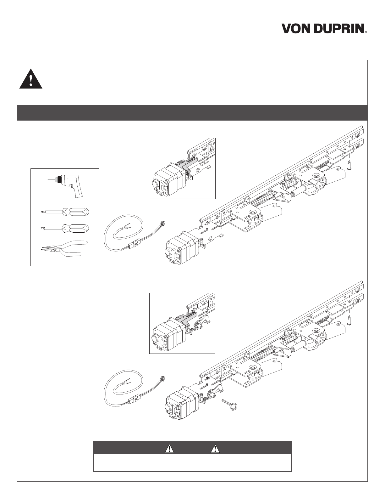
QEL 33A/35A,
24908394
Baseplate Conversion Kit Installation Instructions
1. This kit converts all 33/35A and 98/99 series EL devices and re devices built prior to Oct. 2014 to quiet electric latch (QEL) retraction
devices.
2. QELX and HD-QELX Baseplate Conversion Kits are only for use with Von Duprin AX98/99, AXXP98/99, and AX33A/35A exit devices only.
They are not to be used to convert standard exit devices to QELX.
3. Install according to instructions or device will not function and panic or re label will be void.
4. The QEL wiring must be attached to the re alarm system if installed on re exit hardware.
Tools Required
⁵⁄₈
" Drill Bit
98/99 Series
Parts
QELX Module
QEL Baseplate w/o Dogging (replaces EL Baseplate and Fire Baseplate)
HD-QELX Module
QEL Baseplate with Dogging (replaces EL-HD Baseplate)
WARNING
If existing exit device is re rated, do not install HD-QEL or HD-QELX
(hex dogging) baseplate. Doing so will void re rating.
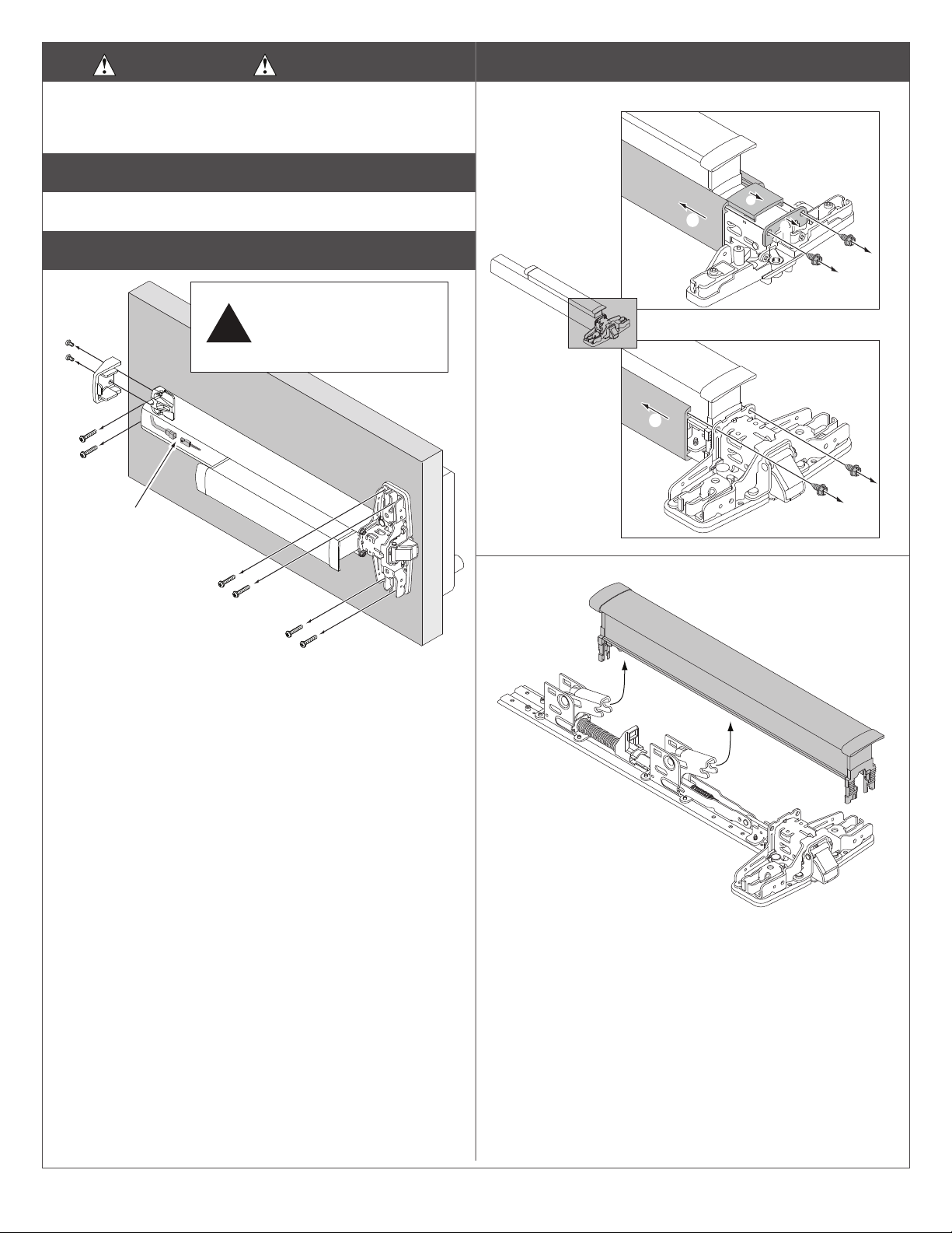
1 Disconnect Power
To avoid risk of shock, disconnect AC power from power supply
before proceeding with this conversion. If using Battery Backup
option, unplug all four wires from battery terminals.
2 Detach Vertical Rods if present
Refer to device instructions as needed.
3 Remove Exit Device from Door
Device and trim must be held
securely while screws are
being removed, to prevent
dropping to the floor
a
c
Unplug cable,
!
b
4 Remove Old Baseplate Assembly
4a Remove Mechanism Case
d
Keep all parts
OR
b
33a/35a
c
b
a
98/99
a
a
4b Remove Pushpad From Baseplate.
d
Keep pushbar
2
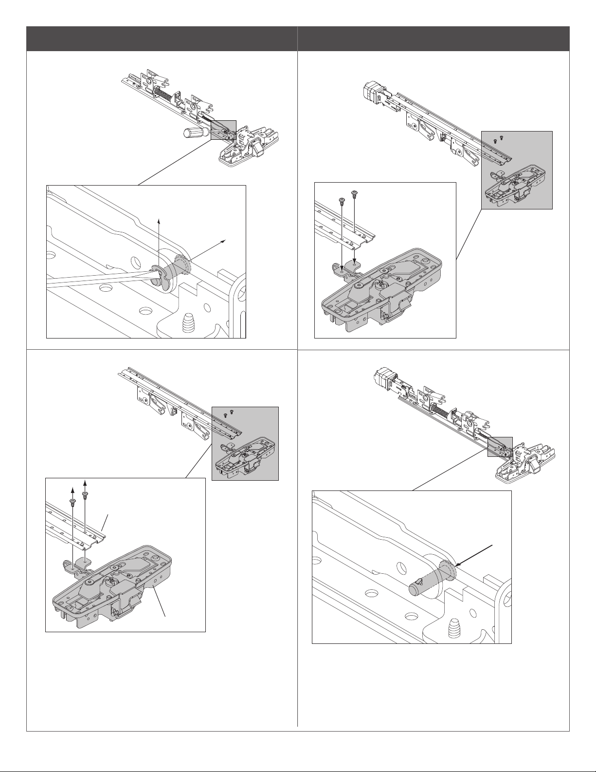
4 Remove Old Baseplate Assembly (continued)
4c Discard retaining ring and pin
Discard retaining ring and pin
5 Install New QEL Baseplate Assembly
5a Attach existing center case to new baseplate using
two screws
4d Discard old baseplate
Discard old baseplate
a
b
5b Install new slic pin
Keep center case
3

5 Install New QEL Assembly (continued)
5c Install pushpad
Ensure plastic clips are
attached
7 Prepare dogging cover for HD dogging key (if
applicablle and only on panic devices).
7a Locate and drill hole
1/4”
Center of Cover
6 Install mechanism case
NOTE: During
step A, verify that
plastic pushbar
clips are aligned
properly inside
case.
Deburr edge of hole
1 1/2”
7b Install dogging cover
33/35
b
a
c
d
8 Drill Wire Access Hole (if required)
⁵⁄₁₆"
OR
Drill ⁵⁄₈" dia. access hole
98/99
a
b
through device side of door.
4

9 Attach Exit Device to Door
Power wires to QEL
d
a
b
For more detailed installation instructions for specic Exit Devices, visit the Support area of the Allegion website at www.allegion.com/us
10 Conrm Equipment Compatibility
The QEL is compatible with the following equipment (refer to individual instructions as needed):
• PS900-SERIES POWER SUPPLIES - PS902, PS904, PS906, PS914
• 900-SERIES OPTION BOARDS - 900-2RS, 900-4R, 900-4RL, 900-2Q
• PS873 POWER SUPPLY PLUS 871-2, 871-2Q, 873-4TD/AO OPTION BOARDS
11 Route Two Wires from QEL Exit Device to Power Supply
QEL Electrical Load
Voltage: 24 VDC
Current: 1.0 A inrush (0.5 sec)
0.14 A holding
PS900-Series power
supply with 900-Series
option board(s)
installed
QEL device used with
EPT, Door Loop, or
Electric Hinge/Pivot
Distance
(one way)
200’ 18AWG
320’ 16AWG
500’ 14AWG
800’ 12AWG
Wire
Gauge
EPT shown. A door loop
or electric hinge/pivot
may also be used.
QEL Exit
Device
Note:
are not polarized.
5

12 Install 900-2Rs, 4Rl, or 4R Option Board(s) into Power Supply
b
c
Secure Board(s) with Screws
Option 1
Option 2
Option 1
Option 3
Option 2
Option 1
PS902
1 Board
PS904, 914
2 Boards
PS906
3 Boards
1
a
Review Available 900 series Option
Board Mounting Locations (Gray)
PS902
PS904
PS914
PS906
1
1 2
2
3
1
Plug Option Board Cable into
any Available Option Connector
3. The QEL is compatible with an existing 900-2Q board
if currently installed.
5. When powering multiple components, verify that the
amperage requirements of all components combined
does not exceed the power supply output rating.
4. Latchbolt retraction of (2) sequenced QEL’s requires
more than 1 second to complete.
2. If installing board in location 2 or 3, rotate board 180˚
Notes: 1. 24VDC output setting required when QEL
device connected
13 Connect Input and Output Wires to Option Board (2RS Shown)
Sequential Mode - Typical Wiring
PS900
Series
SC I1 01 I2 02 GND
Note:
Fail secure
output only
allowed if
approved by
Authority Having
Jurisdiction
120/240 VAC
50/60Hz
2RS
Access
Control
for
Devices
1 & 2
(PS900
Series only)
Input I1 will activate both outputs
QEL Device 1 QEL Device 2
EPT-2/10
EPT-2/10
6
Individual Mode - Typical Wiring
PS900
Series
SC I1 01 I2 02 GND
120/240 VAC
50/60Hz
2RS
Access
Control
for
Device 2
Access
Control
for
Device 1
Input I1 will activate output 1
Input I2 will activate output 2
EPT-2/10
QEL Device 2
QEL Device 1
EPT-2/10

14 Check Operation
A. Activate each input and verify all QEL devices operate properly.
B. If any device does not operate properly, see step 15 for troubleshooting.
15 If Necessary, Troubleshoot Operation (LED is only visible with the mechanism cover removed)
Power at the
QEL
LED - Solid green
Latchbolt - retracted
LED - Solid red after latchbolt
24VDC
24VDC low
29VDC or
greater
13VDC or
lower
0VDC
0VDC
*For information about adjusting exit devices, you can nd their installation instructions in the support area at www.allegion.com/us
or call Technical Services at 1-877-671-7011
attempts to retract multiple times
LED - Flashing green/red
Latchbolt - not retracted
LED - Flashing green
Latchbolt - retracted
LED- Flashing red
Latchbolt - will not retract
LED - o
Latchbolt - not retracted
LED - o
Latchbolt - retracted
QEL Response Condition/Solution
Operation normal, latch retracted immediately
Latchbolt cannot fully retract mechanically
Verify mechanical adjustment (on vertical rod or mortise lock devices
if used). Remove and reapply input voltage to reset this condition.*
See Check Mechanical Operation on page 8 as needed.**
Excessive tamper (while power applied, the pushpad was pulled out
at least 3 time)
Wait 15 seconds and latchbolt will retract again OR remove and
reapply power to clear condition
Voltage low during latchbolt retraction (latchbolt retracts at reduced
force)
Wire length is too long, wire gauge is too small or power supply has
poor regulation
Input voltage is too high for proper operation
Wrong power supply, power supply defective.
Input voltage is too low for proper operation
Wrong power supply, power supply defective or not set to the proper
output voltage.
To set, remove AC power from power supply, change power supply
setting from 12 to 24VDC, then reapply AC power and verify proper
operation.
No input voltage
Problem with the power supply, control switch or wiring
No input voltage
Mechanical dogging is engaged
LED
on Device
7

16 Check Mechanical Operation
33A/3527A 98/9927 98/9947WDC
33A/3547A 98/9947 98/9957
98/9975
1. Make sure device is not dogged for SD-QEL / HD-QEL.
2. Depress pushbar and make sure latch bolt retracts and extends
fully (see Figure 1).
3. If latch bolt does not retract or extend fully, adjustments may be
required per the device installation instructions.
33A/3527A, 98/9927, 98/9957
Latch bolt
deadlocked
(will not
Latch bolt
stays retracted
Release
trigger
extended
push in)
with door
closed
³⁄₁₆"
with door
open
33A/3547A, 98/9947, 98/9947WDC
Latch bolt deadlocked (will not push in)
Flush within ¹⁄₁₆"
⁵⁄₈"
33/3549A 98/9949
33/3550A-WDC 98/9949WDC
98/9950WDC
1. Make sure device is not dogged for SD-QEL/HD-QEL.
2. Depress pushbar. Door should begin to open with pushbar
depressed halfway.
3. Close door. Top latch should be secure. If two point latch, bottom
latch should be secure as well.
4. If device does not function as described in steps 2 and 3,
adjustments may be required per the device installation
instructions.
Any HD Device
1. Fully depress pushbar.
2. Insert hex dogging key and turn clockwise.
3. Release pushbar and verify latchbolt remains retracted.
4. Fully depress pushbar.
5. Insert hex dogging key and turn counter clockwise.
6. Release pushbar and verify latchbolt extends fully.
Latch bolt
extended
98/9975
Latch bolt extended
³⁄₄"
Figure 1
Latch bolt
retracted
Latch bolt retracted
Flush within ¹⁄₁₆"
Customer Service
1-877-671-7011 www.allegion.com/us
© Allegion 2020
Printed in U.S.A.
24908394 Rev. 10/20-e
 Loading...