

Page 1
MA-Series
Service manual
Page 2

Page 3

Contents
4 Introduction
5 Lock assembly drawing index
8 Lock assemblies
9 MA101 - Passage or closet latch
10 MA161 - Exit or connecting room latch
11 MA301 - Privacy lock
12 MA311 - Privacy, bedroom/bath lock
13 MA321 - Privacy lock
14 MA371 - Store door lock
15 MA381 - Apartment, exit lock
16 MA411 - Asylum or institutional lock
17 MA431 - Classroom security lock with deadbolt
18 MA441 - Classroom security lock
19 MA451 - Hotel guest lock
20 MA521 - Entry/oce lock
21 MA531 - Apartment corridor door lock
22 MA541 - Entry/oce lock
23 MA551 - Holdback lock
24 MA561 - Classroom lock
25 MA571 - Dormitory or exit lock
26 MA581 - Storeroom lock
27 MA621 - Apartment corridor lock
28 MA641 - Dormitory lock
29 MA851 - Electrified fail safe (EL) - 12 or 24V, with or
without RX
30 MA881 - Electrified fail secure (EU) - 12 or 24V, with or
without RX
31 MA911 - Classroom dead lock
32 MA921 - Dead lock outside only
33 MA931 - Dead lock inside and outside
34 MA941 - Dead lock with inside turn
35 MA12 - Single dummy
36 MA18 - Double dummy
37 Parts and accessories
37 Lever and knob designs
37 Screw packs
39 Cams
40 Cylinders
40 Mortise, rim, and cam lock for standard cylinders
40 Strikes
41 Cylinder collars
41 Escutcheon trim rings
41 Sectional trim rings
42 Trim rings and collars
43 Electrified locks
44 Ordering procedures
44 Finishes
45 Door handing
Page 4
Introduction
Introduction
This manual contains a complete listing of parts and assemblies for MA-Series mortise locks manufactured by Falcon Lock
Company. This edition lists components of MA-Series locks manufactured aer February, 2011. All lock case covers are
labeled with dates to identify year of manufacture. Example: 2311 = the 23rd week of 2011.
Exploded views of each lock function and trim assembly are provided with accompanying charts to identify parts for
replacement purposes. Exploded views of trim are shown with parts for standard size doors. In addition, this manual provides
lock trim ordering procedures, cylinder length charts by door range, and all auxiliary components of the MA-Series mortise
locks.
Standard features*
Certifications ANSI A156 .13, Series 1000, Grade 1 Operation and Security, UL Listed for 3-hour fire door
Latch 2-piece brass mechanical anti-friction bolt, ³⁄v” projection
Strike 1Z⁄v” x 4M⁄,”, ANSI, Square corner, with dust box
Cylinder 6-Pin solid brass, keyed 5-pin, Falcon G keyway, keyed different (KD)
Door Range 1³⁄v” – 1M⁄,” standard
Keys Two, nickel silver cut keys per lock, Falcon G keyway
Backset 2³⁄v”
* Locks are furnished with standard features unless otherwise specified.
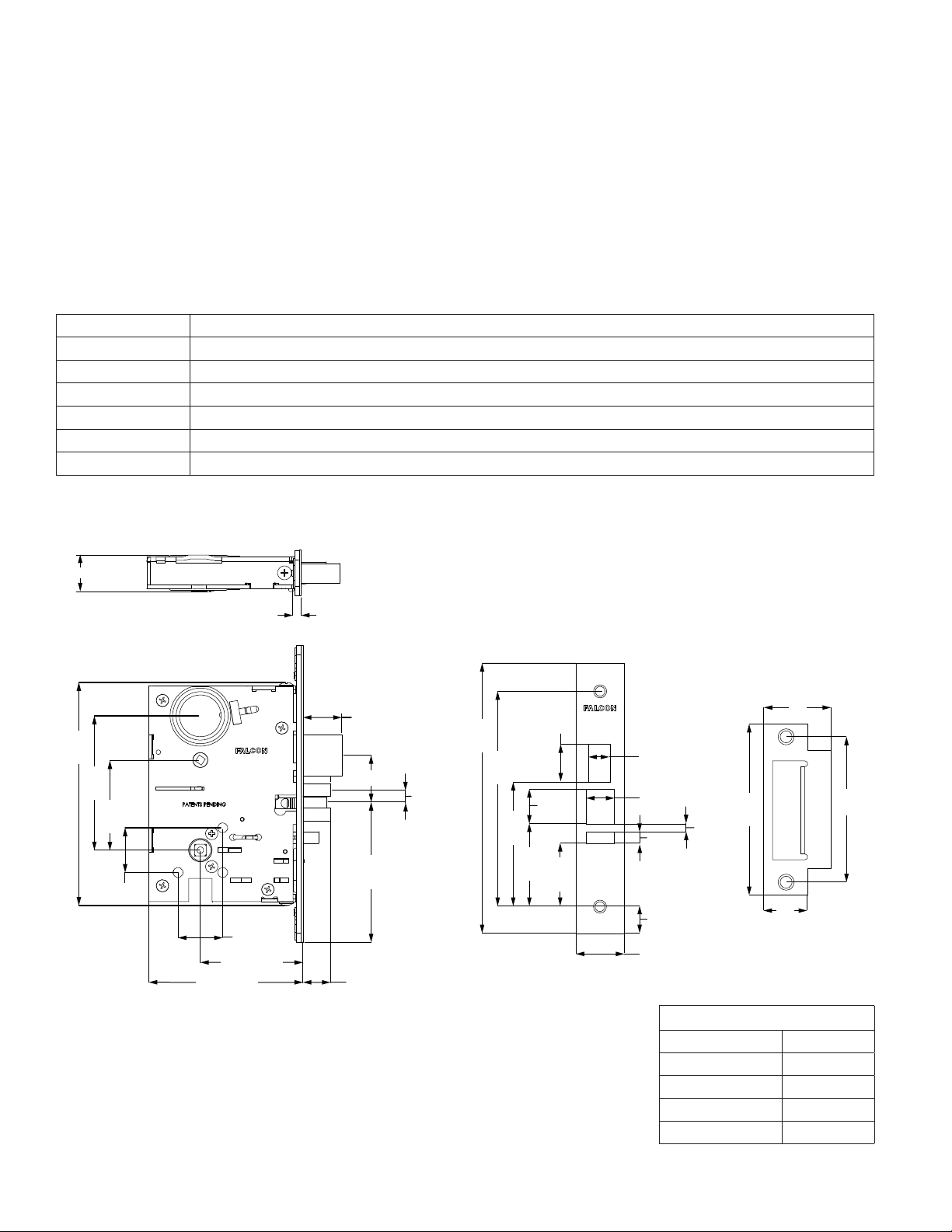
Lock case dimensions
1” (25)
6”
(152)
3³⁹⁄₆₄”
(92)
2²⁷⁄₆₄”
(62)
1³⁄₁₆” (30)
Lock
1³⁄₁₆” (30)
2³⁄₄” (70)
4⁵⁄₃₂” (106)
¹⁄₄” (6)
1” (25)
1¹⁷⁄₆₄” (32)
3⁴⁹⁄₆₄”
(96)
³⁄₄” (19)
²³⁄₁₀₀”
(6)
8”
(203)
6³⁄₈”
(162)
3²¹⁄₃₂”
Faceplate
(93)
2⁷⁄₁₆”
(62)
1⁹⁄₆₄”
1¹⁄₃₂”
(26)
1²⁷⁄₃₂”
(29)
(47)
⁹⁄₁₆” (14)
⁴⁵⁄₆₄” (18)
¹¹⁄₃₂”
(9)
²⁵⁄₃₂” (20)
1¹⁄₄” (32)
¹⁄₄” (6)
4⁷⁄₈”
(124)
A
4¹⁄₈”
(105)
1¹⁄₄”
(32)
Strike
4 • Falcon • MA-Series service manual
Strike
(A) Door thickness Lip size
1³⁄v” - 1M⁄,” 1Z⁄v” (32 mm)
2” - 2Z⁄,” 1M⁄zn” (37 mm)
2Z⁄v” - 2³⁄,” 1>⁄zn” (40 mm)
2Z⁄x” - 2B⁄,” 1ZZ⁄zn” (43 mm)
Page 5
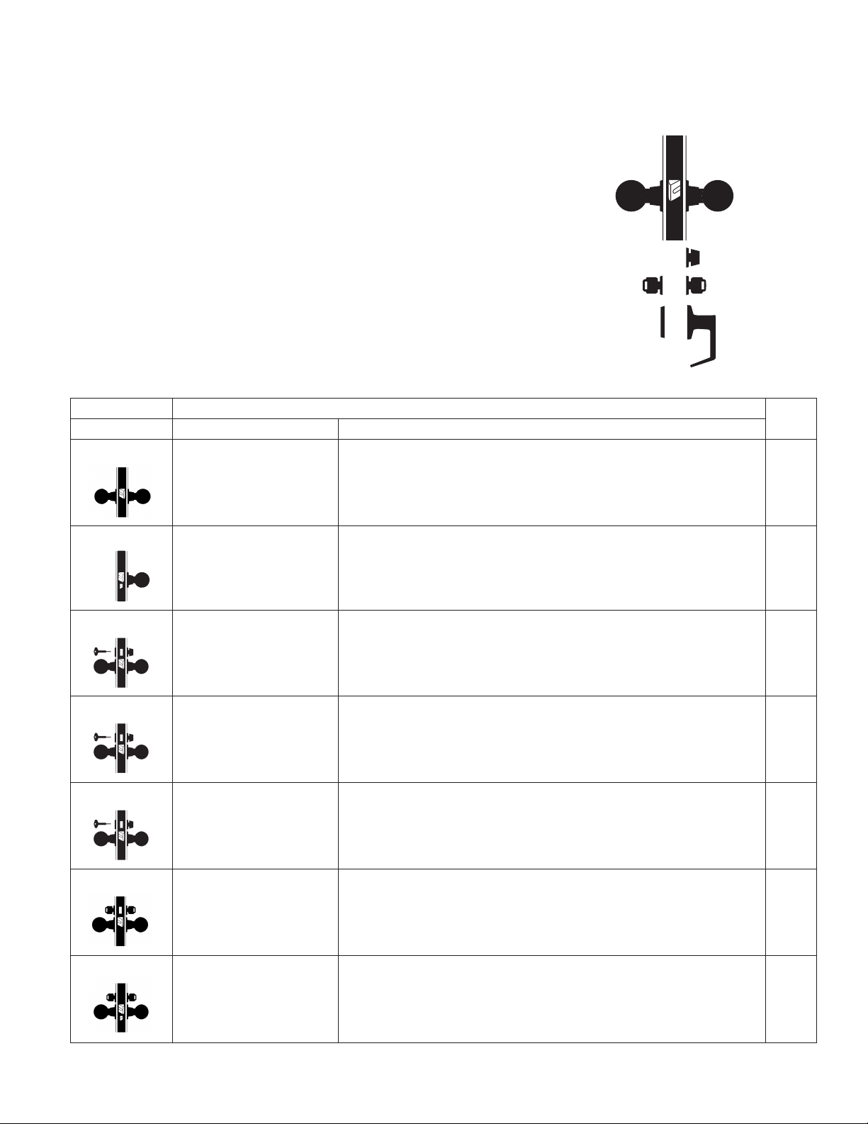
Lock assembly drawing index
Lock assembly drawing index
The lock assembly drawing index provides visual representations and textual
descriptions of available functions. Page numbers for full trim and chassis
drawings are referenced.
To order Falcon MA-Series locksets, please consult page 44 for ordering
information and assistance.
Note: If a special function is required and not listed here, please contact the
factory for assistance.
Knob
Thumb turn
Key
Blank Plate
Function ANSI A156.13, 2005 Page
Falcon ANSI Description Function
MA101 F01 Passage/closet latchset Latch bolt by knob/levers at all times. 9
MA161 F31 Connecting room/exit latch Latch bolt operated by knob/lever from inside. No trim outside. Auxiliary dead latch. 10
MA301 F02 Privacy lock Latch bolt by knobs/levers either side, dead bolt by turn inside or emergency release
outside.
Key
Lever
11
MA311 F19 Privacy, bedroom or bath lock Latch bolt by knobs/levers. Deadbolt by turn from inside and emergency release
outside. Rotating inside knob/lever retracts both bolts.
MA321 F22 Privacy lock Latch bolt operated by knob/lever from either side except when outside knob/lever
is locked by inside thumb turn. Operating inside knob/lever, closing door or
operating outside emergency release unlocks outside knob/lever.
MA371 F14 Store door lock Latch bolt by knobs/levers. Deadbolt by key from either side. 14
MA381 F09 Apartment, exit lock Latch bolt operated by knob/lever from either side, except when outside knob/lever
is locked by key from inside. When outside knob/lever is locked, latch bolt is
retracted by key from outside or by operating inside lever. Auxiliary dead latch.
Falcon • MA-Series service manual • 5
12
13
15
Page 6

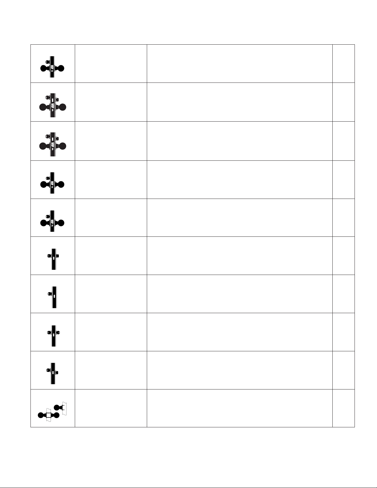
Lock assembly drawing index
MA411 F30 Asylum lock Latch bolt operated by key from either side. Both knobs/levers always inoperative.
MA431 F34 Classroom security lock with
deadbolt
MA441 F32 Classroom security lock Latch bolt operated by knob/lever from either side except when outside knob/lever
MA451 F15 Hotel/guest lock Latch bolt operated by key from outside or by operating inside knob/lever. Outside
MA521 F04 Entry/oce lock Latch bolt operated by knob/lever from either side except when outside knob/lever
Auxiliary dead latch.
Latch bolt operated by knob/lever from either side except when outside knob/lever
is locked from inside or outside by key. Dead bolt retracted by key from inside or
outside. Operating inside knob/lever retracts both bolts and unlocks outside. Latch
bolt dead locked when dead bolt is thrown.
is locked from inside or outside by key. When outside knob/lever is locked, latch bolt
is retracted by key from inside or outside or by operating inside knob/lever. Auxiliary
dead latch.
knob/lever is always inoperative. Dead bolt projected by turn from inside and all
keys except emergency key are shut out. Operating inside knob/lever retracts both
bolts. Auxiliary dead latch.
is made inoperative by buttons in face. When outside knob/lever is locked, latch bolt
is retracted by key from outside or by operating inside knob/lever. Auxiliary dead
latch.
When dead bolt is retracted, knob/lever is unlocked by buttons in face.
16
17
18
19
20
MA531 F20 Apartment corridor door lock Latch bolt operated by knob/lever from either side, except when outside knob/lever
is made inoperative by buttons in face. Dead bolt operated by key outside or turn
inside. Key outside operates both bolts. Operating inside knob/lever retracts both
bolts and outside remains locked.
Latch bolt is deadlocked when outside knob/lever is made inoperative or when the
dead bolt is projected. When dead bolt is retracted, knob/lever is unlocked by
buttons in face.
MA541 F21 Entry/oce lock Latch bolt by knobs/levers either side. Deadbolt by key outside or turn inside. 22
MA551 F06 Holdback lock Latch bolt operated by lever from either side except when outside lever is locked
from outside by key. Latch bolt can be locked in a retracted position by key. When
outside lever is locked, latch bolt is retracted by key from outside or by operating
inside lever unless latch bolt has been locked in a retracted position. Auxiliary dead
latch.
Note: Chassis is handed.
MA561 F05 Classroom lock Latch bolt operated by knob/lever from either side except when outside knob/lever
is locked by key. WHen outside knob/lever is locked, latchbolt is retracted by key
from outside or by operating inside knob/lever. Auxiliary latch deadlocks latch bolt
when door is closed. Inside knob/lever always free for immediate use.
MA571 F13 Dormitory or exit lock Latch bolt operated by knob/lever from either side. Dead bolt projected by key from
outside and turn from inside. Operating inside knob/lever retracts both bolts and
unlocks outside.
21
23
24
25
6 • Falcon • MA-Series service manual
Page 7
Lock assembly drawing index
MA581 F07 Storeroom lock Latch bolt operated by key from outside or by operating inside knob/lever. Otuside
MA621 F08/F10 Front door/apartment corridor Latch bolt is operated by knob/lever from either side except when outside knob/
MA641 - Dormitory lock Latch bolt by knob/lever inside and key outside. Inside knob/lever free. Outside
MA851 - Storeroom - Fail safe (EL),
with or without RX
MA881 - Storeroom - Fail secure (EU),
with or without RX
knob/lever is always inoperative. Auxiliary dead latch.
lever is made inoperative by buttons in face. Dead bolt is operated by turn inside.
Key outside operates both bolts.
knob/lever rigid. Dead bolt by key outside or thumb turn inside. Rotating inside
knob/lever retracts both bolts. Deadlocking latch.
Latch bolt operated by knob/lever from either side except when outside knob/lever
is electrically locked. When outside knob/lever is locked, latch bolt retracted by key
in cylinder outside. Deadlocking latch. Inside knob/lever is always free for
immediate egress.
Specify 12 or 24 V DC.
Latch bolt operated by knob/lever from inside except when outside knob/lever is
electrically unlocked, then latch bolt from either side. When locked, key in outside
cylinder outside retracts latch bolt. Deadlocking latch. Inside knob/lever is always
free for immediate egress.
Specify 12 or 24 V DC.
26
27
28
29
30
MA911 F29 Classroom deadlock Key from outside operates deadbolt. Turn from inside retracts but does not project
dead bolt.
MA921 F18 Deadlock outside only Deadbolt by key outside only. 32
MA931 F16 Deadlock inside and outside Deadbolt by key from either side. 33
MA941 F17 Deadlock with inside turn Deadbolt by key outside or turn inside. 34
MA12/MA18 - Dummy trim Single or double available.
SIngle (MA12).
Double (MA18).
31
35
36
Falcon • MA-Series service manual • 7
Page 8

Lock assemblies
9 MA101 - Passage or closet latch
10 MA161 - Exit or connecting room latch
11 MA301 - Privacy lock
12 MA311 - Privacy, bedroom/bath lock
13 MA321 - Privacy lock
14 MA371 - Store door lock
15 MA381 - Apartment, exit lock
16 MA411 - Asylum or institutional lock
17 MA431 - Classroom security lock with deadbolt
18 MA441 - Classroom security lock
19 MA451 - Hotel guest lock
20 MA521 - Entry/oce lock
21 MA531 - Apartment corridor door lock
22 MA541 - Entry/oce lock
23 MA551 - Holdback lock
24 MA561 - Classroom lock
25 MA571 - Dormitory or exit lock
26 MA581 - Storeroom lock
27 MA621 - Apartment corridor lock
28 MA641 - Dormitory lock
29 MA851 - Electrified fail safe (EL) - 12 or 24V, with or
without RX
30 MA881 - Electrified fail secure (EU) - 12 or 24V, with or
without RX
31 MA911 - Classroom dead lock
32 MA921 - Dead lock outside only
33 MA931 - Dead lock inside and outside
34 MA941 - Dead lock with inside turn
35 MA12 - Single dummy
36 MA18 - Double dummy
8 • Falcon • MA-Series service manual
Page 9

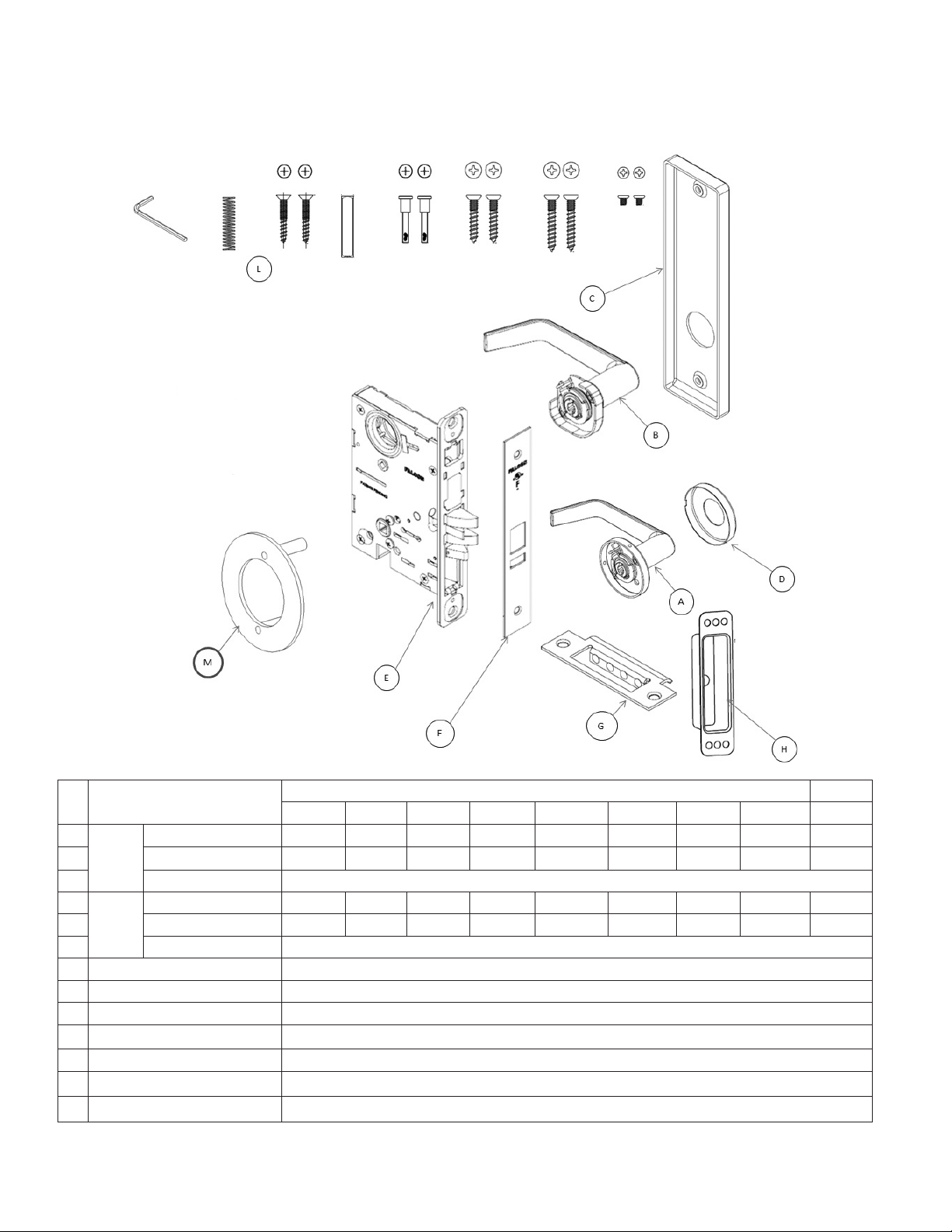
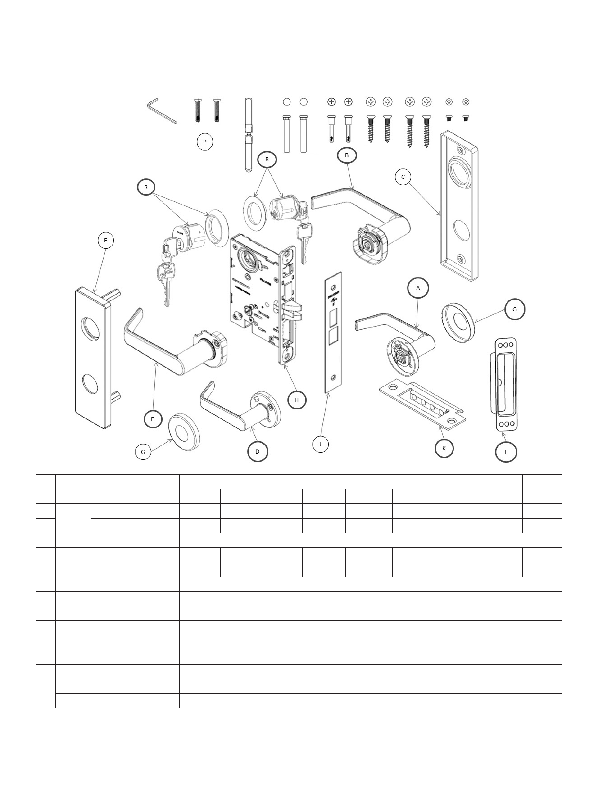
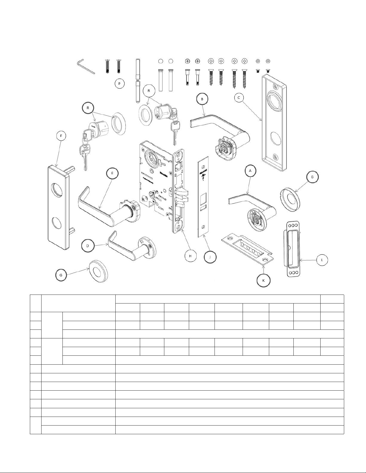
Lock assemblies
MA101 - Passage or closet latch
Ltr. Description
A Inside
trim
B Knob/lever
C Escutcheon E77012-IP
D Outside
trim
E Knob/lever
F Escutcheon AE77012-0P
G Rose (2) S76012
H Assembly, lock unit A7801
J Faceplate S77801
K Strike assembly A8737-X
L Strike box PE1396
P Screw pack See page 37
Knob/lever
sectional
escutcheon
Knob/lever
sectional
escutcheon
Levers Knobs
Dane Sutro Avalon Quantum Boardwalk Broadway Latitude Longitude Hana
AS76280 AS76526 AS76029 AS76140 AS76310 AS76321 AS76360 AS76760 AS76100
AE77280 AE77526 AE77029 AE77140 AE77310 AE77321 AE77360 AE77760 AE77100
AS76280 AS76526 AS76029 AS76140 AS76310 AS76321 AS76360 AS76760 AS76100
AE77280 AE77526 AE77029 AE77140 AE77310 AE77321 AE77360 AE77760 AE77100
Falcon • MA-Series service manual • 9
Page 10
Lock assemblies
MA161 - Exit or connecting room latch
Ltr. Description
A
Inside
B
trim
C Escutcheon E77012-IP
Outside
- Knob/lever escutcheon N /A N /A N/A N/A N/A N/A N/A N/A N/A
trim
- Escutcheon N/A
D Rose S76012
E Assembly, lock unit A7831
F Faceplate S77805
Strike assembly
G
H Strike box PE1396
Screw pack
L
M Plate for use with no outside trim
10 • Falcon • MA-Series service manual
Knob/lever sectional
Knob/lever escutcheon
Knob/lever sectional N/A N/A N/A N /A N/A N/A N/A N/A N/A
Levers Knobs
Dane Sutro Avalon Quantum Boardwalk Broadway Latitude Longitude Hana
AS76280 AS76526 AS76029 AS76140
AE77280 AE77526 AE77029 AE77140
A8737-X
See page 37
AS5813
AS76310 AS76321 AS76360 AS76760
AE77310 AE77321 AE77360 AE77760
AS76100
AE77100
Page 11
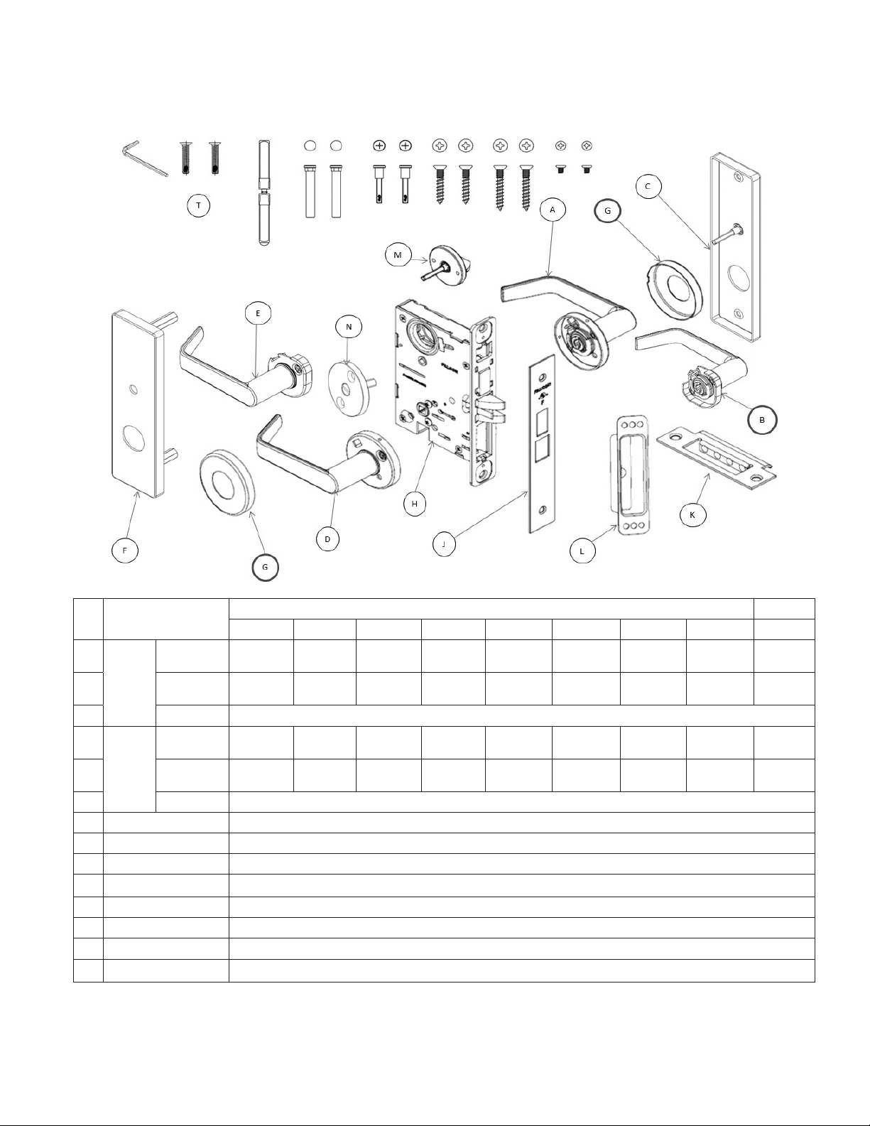
Lock assemblies
MA301 - Privacy lock
Ltr. Description
A Inside
trim
B Knob/lever
C Escutcheon AE77012-IT
D Outside
trim
E Knob/lever
F Escutcheon AE77012-OT
G Rose (2) S76012
H Assembly, lock unit A7802
J Faceplate S77819
K Strike assembly A8737-X
L Strike box PE1396
M Thumb turn AS75319
N Emergency turn AS76853
T Screw pack See page 37
Knob/lever
sectional
escutcheon
Knob/lever
sectional
escutcheon
Levers Knobs
Dane Sutro Avalon Quantum Boardwalk Broadway Latitude Longitude Hana
AS76280 AS76526 AS76029 AS76140 AS76310 AS76321 AS76360 AS76760 AS76100
AE77280 AE77526 AE77029 AE77140 AE77310 AE77321 AE77360 AE77760 AE77100
AS76280 AS76526 AS76029 AS76140 AS76310 AS76321 AS76360 AS76760 AS76100
AE77280 AE77526 AE77029 AE77140 AE77310 AE77321 AE77360 AE77760 AE77100
Falcon • MA-Series service manual • 11
Page 12
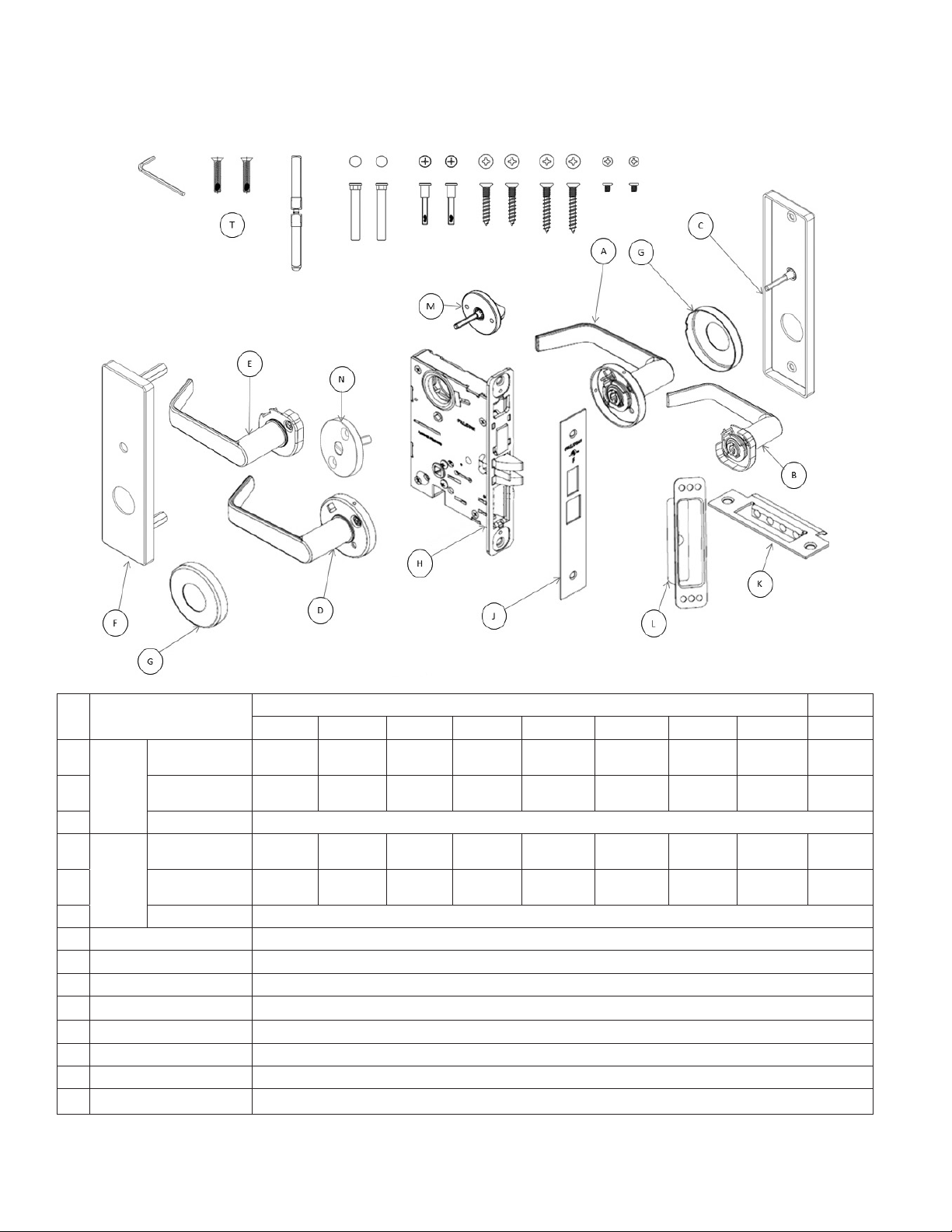
Lock assemblies
MA311 - Privacy, bedroom/bath lock
Ltr. Description
A Inside
trim
B Knob/lever
C Escutcheon AE77012-IT
D Outside
trim
E Knob/lever
F Escutcheon AE77012-OT
G Rose (2) S76012
H Assembly, lock unit A7819
J Faceplate S77819
K Strike assembly A8737-X
L Strike box PE1396
M Thumb turn AS75319
N Emergency turn AS76853
T Screw pack See page 37
Knob/lever
sectional
escutcheon
Knob/lever
sectional
escutcheon
Levers Knobs
Dane Sutro Avalon Quantum Boardwalk Broadway Latitude Longitude Hana
AS76280 AS76526 AS76029 AS76140 AS76310 AS76321 AS76360 AS76760 AS76100
AE77280 AE77526 AE77029 AE77140 AE77310 AE77321 AE77360 AE77760 AE77100
AS76280 AS76526 AS76029 AS76140 AS76310 AS76321 AS76360 AS76760 AS76100
AE77280 AE77526 AE77029 AE77140 AE77310 AE77321 AE77360 AE77760 AE77100
12 • Falcon • MA-Series service manual
Page 13
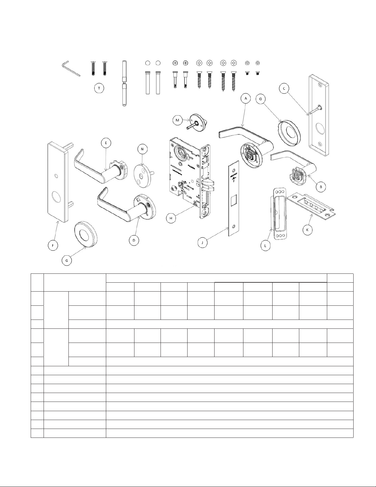
Lock assemblies
MA321 - Privacy lock
Ltr. Description
A
Inside
trim
B
C Escutcheon AE77012-IT
D
Outside
trim
E
F Escutcheon AE77012-OT
G Rose (2) S76012
H Assembly, lock unit A7822
J Faceplate S77801
K Strike assembly A8737-X
L Strike box PE1396
M Thumb turn AS75319
N Emergency turn AS76853
T Screw pack See page 37
Knob/lever
sectional
Knob/lever
escutcheon
Knob/lever
sectional
Knob/lever
escutcheon
Levers Knobs
Dane Sutro Avalon Quantum Boardwalk Broadway Latitude Longitude Hana
AS76280 AS76526 AS76029 AS76140 AS76310 AS76321 AS76360 AS76760 AS76100
AE77280 AE77526 AE77029 AE77140 AE77310 AE77321 AE77360 AE77760 AE77100
AS76280 AS76526 AS76029 AS76140 AS76310 AS76321 AS76360 AS76760 AS76100
AE77280 AE77526 AE77029 AE77140 AE77310 AE77321 AE77360 AE77760 AE77100
Falcon • MA-Series service manual • 13
Page 14
Lock assemblies
MA371 - Store door lock
SFIC not shown
Ltr. Description
A Inside
trim
B Knob/lever escutcheon AE77280 AE77526 AE77029 AE77140 AE77310 AE77321 AE77360 AE77760 AE77100
C Escutcheon E77012-IC
D Outside
trim
E Knob/lever escutcheon AE77280 AE77526 AE77029 AE77140 AE77310 AE77321 AE77360 AE77760 AE77100
F Escutcheon AE77012-OC
G Rose (2) S76012
H Assembly, lock unit A7814
J Faceplate S77819
K Strike assembly A8737-X
L Strike box PE1396
P Screw pack See page 37
R Cylinder, conventional (2) Q005-064
Cylinder, SFIC (2) Q005-065
Knob/lever sectional AS76280 AS76526 AS76029 AS76140 AS76310 AS76321 AS76360 AS76760 AS76100
Knob/lever sectional AS76280 AS76526 AS76029 AS76140 AS76310 AS76321 AS76360 AS76760 AS76100
Levers Knobs
Dane Sutro Avalon Quantum Boardwalk Broadway Latitude Longitude Hana
14 • Falcon • MA-Series service manual
Page 15
Lock assemblies
MA381 - Apartment, exit lock
SFIC not shown
Ltr. Description
A Inside
trim
B Knob/lever escutcheon AE77280 AE77526 AE77029 AE77140 AE77310 AE77321 AE77360 AE77760 AE77100
C Escutcheon E77012-IC
D Outside
trim
E Knob/lever escutcheon AE77280 AE77526 AE77029 AE77140 AE77310 AE77321 AE77360 AE77760 AE77100
F Escutcheon AE77012-OC
G Rose (2) S76012
H Assembly, lock unit A7809
J Faceplate S77805
K Strike assembly A8737-X
L Strike box PE1396
P Screw pack See page 37
R Cylinder, conventional (2) Q005-064
Cylinder, SFIC (2) Q005-065
Knob/lever sectional AS76280 AS76526 AS76029 AS76140 AS76310 AS76321 AS76360 AS76760 AS76100
Knob/lever sectional AS76280 AS76526 AS76029 AS76140 AS76310 AS76321 AS76360 AS76760 AS76100
Levers Knobs
Dane Sutro Avalon Quantum Boardwalk Broadway Latitude Longitude Hana
Falcon • MA-Series service manual • 15
Page 16

Lock assemblies
MA411 - Asylum or institutional lock
SFIC not shown
Ltr. Description
A Inside
trim
B Knob/lever escutcheon AE77280 AE77526 AE77029 AE77140 AE77310 AE77321 AE77360 AE77760 AE77100
C Escutcheon E77012-IC
D Outside
trim
E Knob/lever escutcheon AE77280 AE77526 AE77029 AE77140 AE77310 AE77321 AE77360 AE77760 AE77100
F Escutcheon AE77012-OC
G Rose (2) S76012
H Assembly, lock unit A7814
J Faceplate S77819
K Strike assembly A8737-X
L Strike box PE1396
P Screw pack See page 37
Cylinder, conventional (2) Q005-064
R
Cylinder, SFIC (2) Q005-065
Knob/lever sectional AS76280 AS76526 AS76029 AS76140 AS76310 AS76321 AS76360 AS76760 AS76100
Knob/lever sectional AS76280 AS76526 AS76029 AS76140 AS76310 AS76321 AS76360 AS76760 AS76100
Levers Knobs
Dane Sutro Avalon Quantum Boardwalk Broadway Latitude Longitude Hana
16 • Falcon • MA-Series service manual
Page 17

Lock assemblies
MA431 - Classroom security lock with deadbolt
SFIC not shown
Ltr. Description
A Inside
trim
B Knob/lever escutcheon AE77280 AE77526 AE77029 AE77140 AE77310 AE77321 AE77360 AE77760 AE77100
C Escutcheon E77012-IC
D Outside
trim
E Knob/lever escutcheon AE77280 AE77526 AE77029 AE77140 AE77310 AE77321 AE77360 AE77760 AE77100
F Escutcheon AE77012-OC
G Rose (2) S76012
H Assembly, lock unit A7813
J Faceplate S77819
K Strike assembly A8737-X
L Strike box PE1396
R Screw pack See page 37
T Cylinder, conventional (2) Q005-064
Cylinder, SFIC (2) Q005-065
Knob/lever sectional AS76280 AS76526 AS76029 AS76140 AS76310 AS76321 AS76360 AS76760 AS76100
Knob/lever sectional AS76280 AS76526 AS76029 AS76140 AS76310 AS76321 AS76360 AS76760 AS76100
Levers Knobs
Dane Sutro Avalon Quantum Boardwalk Broadway Latitude Longitude Hana
Falcon • MA-Series service manual • 17
Page 18

Lock assemblies
MA441 - Classroom security lock
SFIC not shown
Ltr. Description
A Inside
trim
B Knob/lever escutcheon AE77280 AE77526 AE77029 AE77140 AE77310 AE77321 AE77360 AE77760 AE77100
C Escutcheon E77012-IC
D Outside
trim
E Knob/lever escutcheon AE77280 AE77526 AE77029 AE77140 AE77310 AE77321 AE77360 AE77760 AE77100
F Escutcheon AE77012-OC
G Rose (2) S76012
H Assembly, lock unit A7805
J Faceplate S77805
K Strike assembly A8737-X
L Strike box PE1396
P Screw pack See page 37
Cylinder, conventional (2) Q005-064
R
Cylinder, SFIC (2) Q005-065
Knob/lever sectional AS76280 AS76526 AS76029 AS76140 AS76310 AS76321 AS76360 AS76760 AS76100
Knob/lever sectional AS76280 AS76526 AS76029 AS76140 AS76310 AS76321 AS76360 AS76760 AS76100
Levers Knobs
Dane Sutro Avalon Quantum Boardwalk Broadway Latitude Longitude Hana
18 • Falcon • MA-Series service manual
Page 19

Lock assemblies
MA451 - Hotel guest lock
Ltr. Description
A Inside
trim
B Knob/lever escutcheon AE77280 AE77526 AE77029 AE77140 AE77310 AE77321 AE77360 AE77760 AE77100
C Escutcheon AE77012-IT
D Outside
trim
E Knob/lever escutcheon AE77280 AE77526 AE77029 AE77140 AE77310 AE77321 AE77360 AE77760 AE77100
F Escutcheon AE77012-OC
G Rose (2) S76012
H Assembly, lock unit A7815
J Faceplate S77815
K Strike assembly A8737-X
L Strike box PE1396
M Thumb turn AS76319
R Screw pack See page 37
T Cylinder, conventional Q005-064
Cylinder, SFIC Q008-065
Knob/lever sectional AS76280 AS76526 AS76029 AS76140 AS76310 AS76321 AS76360 AS76760 AS76100
Knob/lever sectional AS76280 AS76526 AS76029 AS76140 AS76310 AS76321 AS76360 AS76760 AS76100
Levers Knobs
Dane Sutro Avalon Quantum Boardwalk Broadway Latitude Longitude Hana
Falcon • MA-Series service manual • 19
Page 20

Lock assemblies
MA521 - Entry/oce lock
SFIC not shown
Ltr. Description
A Inside
trim
B Knob/lever escutcheon AE77280 AE77526 AE77029 AE77140 AE77310 AE77321 AE77360 AE77760 AE77100
C Escutcheon E77012-IP
D Outside
trim
E Knob/lever escutcheon AE77280 AE77526 AE77029 AE77140 AE77310 AE77321 AE77360 AE77760 AE77100
F Escutcheon AE77012-OC
G Rose (2) S76012
H Assembly, lock unit A7804
J Faceplate S77804
K Strike assembly A8737-X
L Strike box PE1396
P Screw pack See page 37
R Cylinder, conventional Q005-064
Cylinder, SFIC Q005-065
Knob/lever sectional AS76280 AS76526 AS76029 AS76140 AS76310 AS76321 AS76360 AS76760 AS76100
Knob/lever sectional AS76280 AS76526 AS76029 AS76140 AS76310 AS76321 AS76360 AS76760 AS76100
Levers Knobs
Dane Sutro Avalon Quantum Boardwalk Broadway Latitude Longitude Hana
20 • Falcon • MA-Series service manual
Page 21

Lock assemblies
MA531 - Apartment corridor door lock
SFIC not shown
Ltr. Description
A Inside
trim
B Knob/lever escutcheon AE77280 AE77526 AE77029 AE77140 AE77310 AE77321 AE77360 AE77760 AE77100
C Escutcheon AE77012-IT
D Outside
trim
E Knob/lever escutcheon AE77280 AE77526 AE77029 AE77140 AE77310 AE77321 AE77360 AE77760 AE77100
F Escutcheon AE77012-OC
G Rose (2) S76012
H Assembly, lock unit A7820
J Faceplate S77820
K Strike assembly A8737-X
L Strike box PE1396
M Thumb turn AS76319
R Screw pack See page 37
T Cylinder, conventional Q005-064
Cylinder, SFIC Q005-065
Knob/lever sectional AS76280 AS76526 AS76029 AS76140 AS76310 AS76321 AS76360 AS76760 AS76100
Knob/lever sectional AS76280 AS76526 AS76029 AS76140 AS76310 AS76321 AS76360 AS76760 AS76100
Levers Knobs
Dane Sutro Avalon Quantum Boardwalk Broadway Latitude Longitude Hana
Falcon • MA-Series service manual • 21
Page 22

Lock assemblies
MA541 - Entry/oce lock
Ltr. Description
A Inside
trim
B Knob/lever
C Escutcheon AE77012-IT
D Outside
trim
E Knob/lever
F Escutcheon AE77012-OC
G Rose (2) S76012
H Assembly, lock unit A7820
J Faceplate S77820
K Strike assembly A8737-X
L Strike box PE1396
M Thumb turn AS76319
R Screw pack See page 37
T Cylinder, conventional Q005-064
Cylinder, SFIC Q005-065
Knob/lever sectional AS76280 AS76526 AS76029 AS76140 AS76310 AS76321 AS76360 AS76760 AS76100
escutcheon
Knob/lever sectional AS76280 AS76526 AS76029 AS76140 AS76310 AS76321 AS76360 AS76760 AS76100
escutcheon
Levers Knobs
Dane Sutro Avalon Quantum Boardwalk Broadway Latitude Longitude Hana
AE77280 AE77526 AE77029 AE77140 AE77310 AE77321 AE77360 AE77760 AE77100
AE77280 AE77526 AE77029 AE77140 AE77310 AE77321 AE77360 AE77760 AE77100
SFIC not shown
22 • Falcon • MA-Series service manual
Page 23

Lock assemblies
MA551 - Holdback lock
SFIC not shown
Ltr. Description
A Inside
trim
B Knob/lever escutcheon AE77280 AE77526 AE77029 AE77140 AE77310 AE77321 AE77360 AE77760 AE77100
C Escutcheon E77012-IP
D Outside
trim
E Knob/lever escutcheon AE77280 AE77526 AE77029 AE77140 AE77310 AE77321 AE77360 AE77760 AE77100
F Escutcheon AE77012-OC
G Rose (2) S76012
H Assembly, lock unit A7806
J Faceplate S77805
K Strike assembly A8737-X
L Strike box PE1396
P Handing instruction sheet Q513-069
R Screw pack See page 37
T Cylinder, conventional Q005-064
Cylinder, SFIC Q005-065
Knob/lever sectional AS76280 AS76526 AS76029 AS76140 AS76310 AS76321 AS76360 AS76760 AS76100
Knob/lever sectional AS76280 AS76526 AS76029 AS76140 AS76310 AS76321 AS76360 AS76760 AS76100
Levers Knobs
Dane Sutro Avalon Quantum Boardwalk Broadway Latitude Longitude Hana
Falcon • MA-Series service manual • 23
Page 24

Lock assemblies
MA561 - Classroom lock
SFIC not shown
Ltr. Description
A Inside
trim
B Knob/lever escutcheon AE77280 AE77526 AE77029 AE77140 AE77310 AE77321 AE77360 AE77760 AE77100
C Escutcheon E77012-IP
D Outside
trim
E Knob/lever escutcheon AE77280 AE77526 AE77029 AE77140 AE77310 AE77321 AE77360 AE77760 AE77100
F Escutcheon AE77012-OC
G Rose (2) S76012
H Assembly, lock unit A7805
J Faceplate S77805
K Strike assembly A8737-X
L Strike box PE1396
P Screw pack See page 37
R Cylinder, conventional Q005-064
Cylinder, SFIC Q005-065
Knob/lever sectional AS76280 AS76526 AS76029 AS76140 AS76310 AS76321 AS76360 AS76760 AS76100
Knob/lever sectional AS76280 AS76526 AS76029 AS76140 AS76310 AS76321 AS76360 AS76760 AS76100
Levers Knobs
Dane Sutro Avalon Quantum Boardwalk Broadway Latitude Longitude Hana
24 • Falcon • MA-Series service manual
Page 25

Lock assemblies
MA571 - Dormitory or exit lock
SFIC not shown
Ltr. Description
A Inside
trim
B Knob/lever escutcheon AE77280 AE77526 AE77029 AE77140 AE77310 AE77321 AE77360 AE77760 AE77100
C Escutcheon AE77012-IT
D Outside
trim
E Knob/lever escutcheon AE77280 AE77526 AE77029 AE77140 AE77310 AE77321 AE77360 AE77760 AE77100
F Escutcheon AE77012-OC
G Rose (2) S76012
H Assembly, lock unit A7813
J Faceplate S77819
K Strike assembly A8737-X
L Strike box PE1396
M Thumb turn AS76319
R Screw pack See page 37
T Cylinder, conventional Q005-064
Cylinder, SFIC Q005-065
Knob/lever sectional AS76280 AS76526 AS76029 AS76140 AS76310 AS76321 AS76360 AS76760 AS76100
Knob/lever sectional AS76280 AS76526 AS76029 AS76140 AS76310 AS76321 AS76360 AS76760 AS76100
Levers Knobs
Dane Sutro Avalon Quantum Boardwalk Broadway Latitude Longitude Hana
Falcon • MA-Series service manual • 25
Page 26

Lock assemblies
MA581 - Storeroom lock
SFIC not shown
Ltr. Description
A Inside
trim
B Knob/lever escutcheon AE77280 AE77526 AE77029 AE77140 AE77310 AE77321 AE77360 AE77760 AE77100
C Escutcheon E77012-IP
D Outside
trim
E Knob/lever escutcheon AE77280 AE77526 AE77029 AE77140 AE77310 AE77321 AE77360 AE77760 AE77100
F Escutcheon AE77012-OC
G Rose (2) S76012
H Assembly, lock unit A7807
J Faceplate S77805
K Strike assembly A8737-X
L Strike box PE1396
P Screw pack See page 37
R Cylinder, conventional Q005-064
Cylinder, SFIC Q005-065
Knob/lever sectional AS76280 AS76526 AS76029 AS76140 AS76310 AS76321 AS76360 AS76760 AS76100
Knob/lever sectional AS76280 AS76526 AS76029 AS76140 AS76310 AS76321 AS76360 AS76760 AS76100
Levers Knobs
Dane Sutro Avalon Quantum Boardwalk Broadway Latitude Longitude Hana
26 • Falcon • MA-Series service manual
Page 27

Lock assemblies
MA621 - Apartment corridor lock
SFIC not shown
Ltr. Description
A Inside
trim
B Knob/lever escutcheon AE77280 AE77526 AE77029 AE77140 AE77310 AE77321 AE77360 AE77760 AE77100
C Escutcheon AE77012-IT
D Outside
trim
E Knob/lever escutcheon AE77280 AE77526 AE77029 AE77140 AE77310 AE77321 AE77360 AE77760 AE77100
F Escutcheon AE77012-OC
G Rose (2) S76012
H Assembly, lock unit A7808
J Faceplate S77811
K Strike assembly A8737-X
L Strike box PE1396
M Thumb turn AS76319
R Screw pack See page 37
T Cylinder, conventional Q005-064
Cylinder, SFIC Q005-065
Knob/lever sectional AS76280 AS76526 AS76029 AS76140 AS76310 AS76321 AS76360 AS76760 AS76100
Knob/lever sectional AS76280 AS76526 AS76029 AS76140 AS76310 AS76321 AS76360 AS76760 AS76100
Levers Knobs
Dane Sutro Avalon Quantum Boardwalk Broadway Latitude Longitude Hana
Falcon • MA-Series service manual • 27
Page 28

Lock assemblies
MA641 - Dormitory lock
SFIC not shown
Ltr. Description
A Inside
trim
B Knob/lever escutcheon AE77280 AE77526 AE77029 AE77140 AE77310 AE77321 AE77360 AE77760 AE77100
C Escutcheon AE77012-IT
D Outside
trim
E Knob/lever escutcheon AE77280 AE77526 AE77029 AE77140 AE77310 AE77321 AE77360 AE77760 AE77100
F Escutcheon AE77012-OC
G Rose (2) S76012
H Assembly, lock unit A7815
J Faceplate S77815
K Strike assembly A8737-X
L Strike box PE1396
M Thumb turn AS76319
R Screw pack See page 37
Cylinder, conventional Q005-064
T
Cylinder, SFIC Q005-065
Knob/lever sectional AS76280 AS76526 AS76029 AS76140 AS76310 AS76321 AS76360 AS76760 AS76100
Knob/lever sectional AS76280 AS76526 AS76029 AS76140 AS76310 AS76321 AS76360 AS76760 AS76100
Levers Knobs
Dane Sutro Avalon Quantum Boardwalk Broadway Latitude Longitude Hana
28 • Falcon • MA-Series service manual
Page 29

Lock assemblies
MA851 - Electrified fail safe (EL) - 12 or 24V, with or without RX
SFIC not shown
Ltr. Description
A Inside
trim
B Knob/lever escutcheon AE77280 AE77526 AE77029 AE77140 AE77310 AE77321
C Escutcheon E77012-IP
D Outside
trim
E Knob/lever escutcheon AE77280 AE77526 AE77029 AE77140 AE77310 AE77321
F Escutcheon AE77012-OC
G Rose (2) S76012
H Assembly, lock unit A7851-12, A7851-12RX, A7851-24, A7851-24RX
J Faceplate S77805
K Strike assembly A8737-X
L Strike box PE1396
P Screw pack See page 37
R Cylinder, conventional Q005-064
Cylinder, SFIC Q005-065
Knob/lever sectional AS76280 AS76526 AS76029 AS76140 AS76310 AS76321
Knob/lever sectional AS76280 AS76526 AS76029 AS76140 AS76310 AS76321
Levers Knobs
Dane Sutro Avalon Quantum Boardwalk Broadway Latitude Longitude Hana
AS76360 AS76760
AE77360 AE77760
AS76360 AS76760
AE77360 AE77760
Falcon • MA-Series service manual • 29
AS76100
AE77100
AS76100
AE77100
Page 30

Lock assemblies
MA881 - Electrified fail secure (EU) - 12 or 24V, with or without RX
SFIC not shown
Ltr. Description
A Inside
trim
B Knob/lever escutcheon AE77280 AE77526 AE77029 AE77140 AE77310 AE77321 AE77360 AE77760 AE77100
C Escutcheon E77012-IP
D Outside
trim
E Knob/lever escutcheon AE77280 AE77526 AE77029 AE77140 AE77310 AE77321 AE77360 AE77760 AE77100
F Escutcheon AE77012-OC
G Rose (2) S76012
H Assembly, lock unit A7881-12, A7881-12RX, A7881-24, A7881-24RX
J Faceplate S77805
K Strike assembly A8737-X
L Strike box PE1396
R Screw pack See page 37
T Cylinder, conventional Q005-064
Cylinder, SFIC Q005-065
Knob/lever sectional AS76280 AS76526 AS76029 AS76140 AS76310 AS76321 AS76360 AS76760 AS76100
Knob/lever sectional AS76280 AS76526 AS76029 AS76140 AS76310 AS76321 AS76360 AS76760 AS76100
Levers Knobs
Dane Sutro Avalon Quantum Boardwalk Broadway Latitude Longitude Hana
30 • Falcon • MA-Series service manual
Page 31

Lock assemblies
MA911 - Classroom dead lock
SFIC not shown
Ltr. Description
- Inside
trim
- Knob/lever escutcheon N/R N/R N/R N/R N/R N/R N/R N/R N/R
A Escutcheon AE77012-IE
- Outside
trim
- Knob/lever escutcheon N/R N/R N/R N/R N/R N/R N/R N/R N/R
B Escutcheon AE77012-OK
C Assembly, lock unit A7829
D Faceplate S77816
E Strike assembly A8737-X
F Strike box PE1396
G Thumb turn AS76319
K Screw pack See page 37
L Cylinder, conventional Q005-064
Cylinder, SFIC Q005-065
Knob/lever sectional N/R N/R N/R N/R N/R N/R N/R N/R N/R
Knob/lever sectional N/R N/R N/R N/R N/R N/R N/R N/R N/R
Levers Knobs
Dane Sutro Avalon Quantum Boardwalk Broadway Latitude Longitude Hana
Falcon • MA-Series service manual • 31
Page 32

Lock assemblies
MA921 - Dead lock outside only
Ltr. Description
- Inside
trim
- Knob/lever
A Escutcheon E77012-IB
- Outside
trim
- Knob/lever
B Escutcheon AE77012-OK
C Assembly, lock unit A7816
D Faceplate S77816
E Strike assembly A8737-X
F Strike box PE1396
J Screw pack See page 37
K Cylinder, conventional Q005-064
Cylinder, SFIC Q005-065
Knob/lever
sectional
escutcheon
Knob/lever
sectional
escutcheon
Levers Knobs
Dane Sutro Avalon Quantum Boardwalk Broadway Latitude Longitude Hana
N/R N/R N/R N/R N/R N/R N/R N/R N/R
N/R N/R N/R N/R N/R N/R N/R N/R N/R
N/R N/R N/R N/R N/R N/R N/R N/R N/R
N/R N/R N/R N/R N/R N/R N/R N/R N/R
32 • Falcon • MA-Series service manual
Page 33

Lock assemblies
MA931 - Dead lock inside and outside
Ltr. Description
- Inside
trim
- Knob/lever
A Escutcheon E77012-IK
- Outside
trim
- Knob/lever
B Escutcheon AE77012-OK
C Assembly, lock unit A7816
D Faceplate S77816
E Strike assembly A8737-X
F Strike box PE1396
J Screw pack See page 37
K Cylinder, conventional (2) Q005-064
Cylinder, SFIC (2) Q005-065
Knob/lever
sectional
escutcheon
Knob/lever
sectional
escutcheon
Levers Knobs
Dane Sutro Avalon Quantum Boardwalk Broadway Latitude Longitude Hana
N/R N/R N/R N/R N/R N/R N/R N/R N/R
N/R N/R N/R N/R N/R N/R N/R N/R N/R
N/R N/R N/R N/R N/R N/R N/R N/R N/R
N/R N/R N/R N/R N/R N/R N/R N/R N/R
SFIC not shown
Falcon • MA-Series service manual • 33
Page 34

Lock assemblies
MA941 - Dead lock with inside turn
SFIC not shown
Ltr. Description
- Inside
trim
- Knob/lever escutcheon N/R N/R N/R N/R N/R N/R N/R N/R N/R
A Escutcheon E77012-IK
- Outside
trim
- Knob/lever escutcheon N/R N/R N/R N/R N/R N/R N/R N/R N/R
B Escutcheon AE77012-OK
C Assembly, lock unit A7816
D Faceplate S77816
E Strike assembly A8737-X
F Strike box PE1396
J Screw pack See page 37
K Cylinder, conventional (2) Q005-064
Cylinder, SFIC (2) Q005-065
Knob/lever sectional N/R N/R N/R N/R N/R N/R N/R N/R N/R
Knob/lever sectional N/R N/R N/R N/R N/R N/R N/R N/R N/R
Levers Knobs
Dane Sutro Avalon Quantum Boardwalk Broadway Latitude Longitude Hana
34 • Falcon • MA-Series service manual
Page 35

Lock assemblies
MA12 - Single dummy
Knobs/Levers on
One Side Fixed
Ltr.
Description Dane Sutro Avalon Quantum Boardwalk Broadway Latitude Longitude Hana
A Trim Knob/lever
B Knob/lever
C Escutcheon E77012-IP
D Rose S76012
F Screw pack S76331
sectional
escutcheon
Torx screw pack
(optional)
Levers Knobs
AS76280-D AS76526-D AS76029-D AS76140-D AS76310 AS76321 AS76360 AS76760 AS76100-D
AE77280-D AE77526-D AE77029-D AE77140-D AE77310 AE77321 AE77360 AE77760 AE77100-D
E77308
Falcon • MA-Series service manual • 35
Page 36

Lock assemblies
MA18 - Double dummy
Knobs/Levers on
Both Sides Fixed
Ltr.
Description Dane Sutro Avalon Quantum Boardwalk Broadway Latitude Longitude Hana
A Inside
trim
B Knob/lever
C Escutcheon E77012-IP
D Outside
trim
E Knob/lever
F Escutcheon AE77012-0P
G Rose (2) S76012
K Screw pack See page 37
Knob/lever
sectional
escutcheon
Knob/lever
sectional
escutcheon
Levers Knobs
AS76280-D AS76526-D AS76029-D AS76140-D AS76310 AS76321 AS76360 AS76760 AS76100-D
AE77280-D AE77526-D AE77029-D AE77140-D AE77310 AE77321 AE77360 AE77760 AE77100-D
AS76280-D AS76526-D AS76029-D AS76140-D AS76310 AS76321 AS76360 AS76760 AS76100-D
AE77280-D AE77526-D AE77029-D AE77140-D AE77310 AE77321 AE77360 AE77760 AE77100-D
36 • Falcon • MA-Series service manual
Page 37

Parts and accessories
Parts and accessories
Lever and knob designs
Gala
AG (Avalon-Gala)
BOG (Boardwalk-Gala)
Napa
AN (Avalon-Napa)
BON (Boardwalk-Napa)
DG (Dane-Gala)
BRG (Broadway-Gala)
DN (Dane-Napa)
BRN (Broadway-Napa)
QG (Quantum-Gala)
LTG (Latitude-Gala)
QN (Quantum-Napa)
LTN (Latitude-Napa)
SG (Sutro-Gala)
LGG (Longitude-Gala)
SN (Sutro-Napa)
LGN (Longitude-Napa)
HG (Hana-Gala)
HN (Hana-Napa)
Screw packs
Part No. Description Use
S76300 #8-32 x Z⁄v” L machine screw 1 ³⁄,”-1M⁄,” door
#12-12 / #12-24 x 1Z⁄x” L wood/machine
combination screw
#12-12 / #12-24 x 1Z⁄v” L wood/machine
combination screw
#8-32 x 1Z⁄v” L mounting screw
ø Z⁄v” x 1ZZ⁄zn” L post
B⁄zn” x 1>⁄zn” L x 2 pcs STD spindle assembly
³⁄cx” Allen wrench
thickness,
sectional trim
with levers
Part No. Description Use
S76301 #8-32 x Z⁄v” L machine screw Over 1M⁄,”-2Z⁄x”
#12-12 / #12-24 x 1Z⁄x” L wood/machine
combination screw
#12-12 / #12-24 x 1Z⁄v” L wood/machine
combination screw
#8-32 x 1Z⁄x” L mounting screw
ø Z⁄v” x 2Z⁄v” L post
B⁄zn” x 1M⁄,” L x 2 pcs EXT spindle assembly
³⁄cx” Allen wrench
Falcon • MA-Series service manual • 37
door thickness,
sectional trim
with levers
Page 38

Parts and accessories
Part No. Description Use
S76302 #8-32 x Z⁄v” L machine dcrew 1³⁄,” -1M⁄,” door
#12-12 / #12-24 x 1Z⁄x” L wood/machine
combination screw
#12-12 / #12-24 x 1Z⁄v” L wood/machine
combination screw
#8-32 x 1Z⁄v” L mounting screw
ø Z⁄v” x 1ZZ⁄zn” L post
B⁄zn” x 1Z⁄v” L x 2 pcs STD spindle assembly
³⁄cx” Allen wrench
S76303 #8-32 x Z⁄v” L machine screw Over 1M⁄,”-2Z⁄x”
#12-12 / #12-24 x 1Z⁄x” L wood/machine
combination screw
#12-12 / #12-24 x 1Z⁄v” L wood/machine
combination screw
#8-32 x 1Z⁄x” L mounting screw
ø Z⁄v” x 2Z⁄v” L post
B⁄zn” x 1>⁄zn” L x 2 pcs EXT spindle assembly
³⁄cx” Allen wrench
S76306 #8-32 x Z⁄v” L Torx� head machine screw Torx screw
#12-12 / #12-24 x 1Z⁄x” L Torx head
wood/machine combination screw
S76307 #8-32 x Z⁄v” L Torx head machine screw Torx screw
#12-12 / #12-24 x 1Z⁄x” L Torx head
wood/machine combination screw
#6 x Z⁄x” Torx head sheet metal screw
S76331 #8-32 x Z⁄v” L machine screw Single dummy
#12-12 / #12-24 x 1Z⁄x” L wood/machine
combination screw
#12-12 / #12-24 x 1Z⁄v” L wood/machine
combination screw
#8-32 x 1Z⁄v” L mounting screw
B⁄zn” x 1>⁄zn” L STD spindle
ø 0.027” Wire, OD; ø B⁄zn” x 1³⁄,” L spring
³⁄cx” Allen wrench
E77300 #8-32 x Z⁄v” L machine screw 1³⁄,”-1M⁄,” door
#12-12 / #12-24 x 1Z⁄x” wood/machine
combination screw
#12-12 / #12-24 x 1Z⁄v” L wood/machine
combination screw
#8-32 x 1Z⁄v” L mounting screw
ø Z⁄v” x 1ZZ⁄zn” L post
B⁄zn” x 1>⁄zn” L x 2 pcs STD spindle assembly
#10-24 x 1Z⁄v” machine screw
³⁄cx” Allen wrench
E77301 #8-32 x Z⁄v” L machine screw Over 1M⁄,”-2Z⁄x”
#12-12 / #12-24 x 1Z⁄x” L wood/machine
combination screw
#12-12 / #12-24 x 1Z⁄v” L wood/machine
combination screw
#8-32 x 1Z⁄x” L mounting screw
ø Z⁄v” x 2Z⁄v” L post
B⁄zn” x 1M⁄,” L x 2 pcs EXT spindle assembly
#10-24 x 2” machine screw
³⁄cx” Allen wrench
thickness,
sectional trim
with knobs
door thickness,
sectional trim
with knobs
pack, sectional
trim, no turn
pack, sectional
trim, with turn
thickness,
escutcheon
trim with levers
door thickness,
escutcheon
trim with levers
Part No. Description Use
E77302 #8-32 x Z⁄v” L machine screw 1³⁄,”-1M⁄,” door
#12-12 / #12-24 x 1Z⁄x” L wood/machine
combination screw
#12-12 / #12-24 x 1Z⁄v” L wood/machine
combination screw
#8-32 x 1Z⁄v” L mounting screw
ø Z⁄v” x 1ZZ⁄zn” L post
B⁄zn” x 1Z⁄v” L x 2 pcs STD knob spindle
assembly
#10-24 x 1Z⁄v” L machine screw
³⁄cx” Allen wrench
E77303 #8-32 x Z⁄v” L machine screw Over 1M⁄,”-2Z⁄x”
#12-12 / #12-24 x 1Z⁄x” L wood/machine
combination screw
#12-12 / #12-24 x 1Z⁄v” L wood/machine
combination screw
#8-32 x 1Z⁄x” L trim screw
ø Z⁄v” x 1ZZ⁄zn” L Post
B⁄zn” x 1>⁄zn” L x 2 pcs EXT spindle assembly
#10-24 x 2” L machine screw
³⁄cx” Allen wrench
E77306 #8-32 x Z⁄v” L Torx head machine screw 1 ³⁄,”-1M⁄,” door
#12-12 / #12-24 x 1Z⁄x” L Torx head
wood/machine combination screw
#10-24 x 1Z⁄v” L Torx head, machine screw
E77307 #8-32 x Z⁄v” L Torx head machine screw Over 1M⁄,”-2Z⁄x”
#12-12 / #12-24 x 1Z⁄x” L Torx head
wood/machine combination screw
#10-24 x 2” L Torx head machine screw
E77308 #8-32 x Z⁄v” L Torx head machine screw Torx screw
#12-12 / #12-24 x 1Z⁄x” L Torx head
wood/machine screw
#10-24 / #10 x 1Z⁄v” L Torx head
wood/machine screw
E77331 #8-32 x Z⁄v” L machine screw Escutcheon
#12-12 / #12-24 x 1Z⁄x” L wood/machine
combination screw
#12-12/#12-24 x 1Z⁄v” L wood/machine
combination screw
#8-32 x 1Z⁄v” L mounting screw
B⁄zn” x 1>⁄zn” L STD spindle
#10-24 / #10 x 1Z⁄v” L wood/machine
combination screw
ø 0.027 Wire, ø B⁄zn” O.D. x 1³⁄,” L spring
³⁄cx” Allen wrench
Available in finishes 606, 613, 630.
Non Torx screw packs contain armor front screws, strike screws, trim
screws, mortise screws, spindle, and mounting posts.
Torx screw packs contain armor front, strike, and trim screws only.
thickness,
escutcheon
trim with knob
door thickness,
escutcheon
trim with knob
thickness Torx
screw pack,
escutcheon
trim, standard
door thickness
door thickness
Torx screw
pack,
escutcheon
trim, extended
door thickness
pack, rose
escutcheon
connection
door
connecting
door
38 • Falcon • MA-Series service manual
Page 39

Parts and accessories
Cams
Cams for Falcon mortise cylinders (except MA381 function)
The Falcon MA-Series requires a different cam for keyed functions than its predecessor, the Falcon M Series. All keyed
functions except the MA381 function use a single cam for all standard cylinders and a single cam for all interchangeable
core cylinders.
Door handing Cam part number Outside Inside For cylinder
All 5622-STD (F1) MA371, MA411, MA431, MA441, MA451, MA521, MA531, MA541,
MA551, MA561, MA571, MA581, MA621, MA641, MA851, MA881,
MA911, MA921, MA931, MA941
All 5622-IC (F2) MA371, MA411, MA431, MA441, MA451, MA521, MA531, MA541,
MA551, MA561, MA571, MA581, MA621, MA641, MA851, MA881,
MA911, MA921, MA931, MA941
5622-STD (F1) 5622-IC (F2)
MA371, MA411, MA431,
MA441, MA931
MA371, MA411, MA431,
MA441, MA931
Standard
Interchangeable
core
Cams for Falcon mortise cylinders, MA381 function only
The Falcon MA381 function uses unique cams. Different cams are required depending on the handing of the lock.
Complete cylinders can also be ordered for the MA381 function that include the correct cam (handing must be specified
when ordering cylinders for the MA381). See current Falcon Price Book for details.
Cylinder Door handing Outside cylinder cam part number Inside cylinder cam part number
Standard RH/RHR 5621-STD (R4) 5620-STD (R3)
LH/LHR 5621-STD (L4) 5620-STD (L3)
Interchangeable core RH/RHR 5621-IC (R4) 5620-IC (R3)
LH/LHR 5621-IC (L4) 5620-IC (L3)
MA381 Standard cylinder, outside MA381 Standard cylinder, inside
5621-STD (R4)
R4
MA381 Interchangeable core cylinder, outside MA381 Interchangeable core cylinder, inside
5621-IC (R4)
5621-STD (L4)
L4
5621-IC (L4)
5620-STD (R3)
R
5620-IC (R3)
5620-STD (L3)
5620-IC (R3)
R4
L4
R
Cams for Schlage cylinders
The Schlage Classic cylinders (C, E, and CE keyways) will also operate the Falcon MA-Series locks using the 5622-STD cam.
Falcon • MA-Series service manual • 39
Page 40

Cylinders
Cylinders
Mortise, rim, and cam lock for standard cylinders
Mortise cylinder
900 Series cylinders are furnished
with #4 straight cam, and 250
Series are furnished with #1
cloverleaf cam unless otherwise
specified.
See table for product numbers.
See page 39 for optional cams
and page 42 for collars.
Specify finish: 605, 606, 612, 613,
626, 629, 630
Thumbturn cylinder
Furnished with #4 straight cam,
except 970 Series furnished
with #1 cloverleaf cam unless
otherwise specified.
See table for product numbers.
See page 39 for optional
cams and page 42 for
collars.
Specify finish: 605, 606, 612,
613, 626, 629, 630
Dummy cylinder
Used to plug hole in door where
lock remains but cylinder
operation is no longer needed.
984 1”
985 1Z⁄,”
Specify finish: 605, 606, 612, 613,
626, 629, 630
Keyed mortise cylinders
Number Length Pins Application
985 1Z⁄,” 5 or 6 Generic
986 1Z⁄v” 5 or 6 Generic
987 1³⁄,” 6 or 7 Generic
988 1Z⁄x” 6 or 7 Generic
990 1³⁄v” 6 or 7 Generic
992 2” 6 or 7 Generic
250 1Z⁄,” 6 M451 hotel function
251 1Z⁄v” 6 M451 hotel function
252 1³⁄,” 6 M451 hotel function
253 1³⁄,” 7 M451 hotel function
Thumbturn mortise cylinders
Number Length Pins Application
985T 1Z⁄,” - Generic
986T 1Z⁄v” - Generic
973 1Z⁄,” - M911 classroom thumbturn, RH
(CCW)
974 1Z⁄,” - M911 classroom thumbturn, LH
(CW)
Specify cylinder number, keyway, and finish when ordering.
Strikes
Strike Lip length (x) Lip
A8737-1 1Z⁄v” Curved lip
A8737-2 1M⁄zn” Curved lip
A8737-3 1>⁄zn” Curved lip
A8737-4 1ZZ⁄zn” Curved lip
A8737-5 M⁄,” Straight lip
40 • Falcon • MA-Series service manual
Lip
Length
(x)
Page 41

Cylinders
Cylinder collars
Standard collars for cylinders ordered separately
Length Cylinder Non-AR cams AR cam
1” 984D A08794-000 -
1Z⁄,” 250, 965, 966, 973, 974, 985 Series A08794-000 008876-002
1Z⁄v” 251, 986 Series A08794-001 008876-003
1³⁄,” 252, 253, 987, C987, C997 A08794-002 008876-004
Longer C260 Series, (C)988, (C)990, (C)992 A08794-000 008876-000
Escutcheon trim rings
Door
thickness
1Z⁄x” Single cylinder - A08790-000 A08790-001 A08790-002
1Z⁄x” Double cylinder A08790-000 - - -
1³⁄v” Single cylinder - - A08790-000 A08790-001
1³⁄v” Double cylinder - A08790-000 A08790-001 A08790-002
2” Single cylinder - - A08790-000 A08790-001
2” Double cylinder - - A08790-000 A08790-001
2Z⁄v” Single cylinder - - - A08790-000
2Z⁄v” Double cylinder - - - -
2Z⁄x” Single cylinder - - - -
2Z⁄x” Double cylinder - - -
Function 985
1Z\,”
986
1Z\v”
(C) 987
1C\,”
(C) 988
1Z\x”
-
Sectional trim rings
Door
thickness
1Z⁄x” Single cylinder A08794-001 A08794-002 - -
1Z⁄x” Double cylinder A08794-002 A08794-003 - -
1³⁄v” Single cylinder A08794-000 A08794-001 - -
1³⁄v” Double cylinder A08794-001 A08794-002 A08794-002 -
2” Single cylinder - A08794-000 A08794-001 A08794-002
2” Double cylinder A08794-000 A08794-001 A08794-002 A08794-003
2Z⁄v” Single cylinder - - A08794-000 A08794-001
2Z⁄v” Double cylinder - A08794-000 A08794-001 A08794-002
2Z⁄x” Single cylinder - - - A08794-000
2Z⁄x” Double cylinder - - A08794-000 A08794-001
Specify part number and finish when ordering. (e.g. A08790-000-626). See current Falcon Price Book for available finishes.
Function 985
1Z\,”
986
1Z\v”
(C) 987
1C\,”
(C) 988
1Z\x”
Falcon • MA-Series service manual • 41
Page 42

Cylinders
Trim rings and collars
Dim. A Dim. B Part No.
³⁄cx” >⁄cx” A08790-000
A
B
B
A
Blocking rings
M⁄cx” 1³⁄cx” A08790-001
ZZ⁄cx” 1M⁄cx” A08790-002
ZB⁄cx” XZ⁄cx” A08790-003
V³⁄nv” BB⁄nv” A08790-004
³⁄cx” >⁄cx” A08794-000
M⁄cx” 1³⁄cx” A08794-001
A
ZZ⁄cx” 1M⁄cx” A08794-002
ZB⁄cx” XZ⁄cx” A08794-003
Z⁄,” - 008876-000
³⁄zn” - 008876-005
Z⁄v” - 008876-001
³⁄,” - 008876-002
Z⁄x” - 008876-003
B⁄,” - 008876-004
Wave washer included.
To order separately,
specify 008789-001-60.
Specify part number and finish when ordering. (e.g. A08790-000-626). See current Falcon Price Book for available finishes.
42 • Falcon • MA-Series service manual
Page 43

Electrified locks
Electrified locks
All MA851 and MA881 locks feature automatic detection and
operation with 12V or 24V DC. Locks are furnished with
Allegion Connect molex connector with 3-inch lead. Allegion
Connect system allows rapid installation of locks when used
with Allegion Connect harnesses and hinges. The molex
connector can be cut off to allow for installation by splicing.
It is recommended that all wiring be done by a licensed
electrician familiar with the supporting equipment.
MA851 EL, Electrically locked (fail safe)
Outside trim is continuously locked electrically. The latchbolt
is retracted by a key outside or by the knob/lever inside. Switch
or power failure allows the outside knob/lever to retract the
latchbolt.
MA881 EU, Electrically unlocked (fail secure)
Outside trim is unlocked electrically. Duringt switch or power
failure, the latchbolt is retracted only by a key outside, or by
knob/lever inside. Outside knob/lever will not retract latchbolt
during switch or power failure.
Typical Installation:
All installations should be in accordance with local electrical
codes and National Electrical Code NFPA #70.
It is recommended that each lock have its own 12 or 24 volt
transformer. Be sure to select the proper transformer for the
lock.
Two or more locks may be operated in parallel from a single
transformer provided it has the necessary current rating.
DO NOT connect locks in series from a higher voltage rated
transformer. Damage to locks may occur if they connect to a
supply circuit that also contains electromagnetic devices.
The transient voltage must be suppressed at the equipment
producing them before connecting the locks to a circuit.
A varistor rate at 35 volts (at peak current) may be used for
transient voltage protection.
IMPORTANT: Cable must be routed and tucked to fit. Ensure
that no wires are exposed or pinched during positioning.
1. Prepare mortise pocket in door per template. Access for
the wiring to be per installer’s requirements. It is
recommended that an access channel is bored to provide
contact from the electric transfer hinge or other means of
transfer to the mortise pocket.
2. Connect wires as necessary (some options may not be
used), and slip the mortise into the prepared pocket in the
door. Take care to ensure wires are not pinched or
damaged.
3. Always ensure door operates properly before locking!
Solenoid operated lock
* (not furnished)
Solenoid (Electrically
Locking/Unlocking)
12V DC - Black wires /
24V DC - White wires
RX Switch
Normally open - Green wire
Common RX switch
Common - Orange wire
Rectifier*
Door
connector*
Install varistor
here if used*
Switch*
Operating Temperature: Max +151° F (+ 66° C), Min. -31° F (-0.5° C)
Voltage: 12V DC +/- 10% 24V DC +/- 10%
Operating Current: 0.42 A 0.21 A
Holding Current: 0.135 A
12 or 24V AC
Electrical requirements
110V AC
Transformer*
Falcon • MA-Series service manual • 43
Page 44

Ordering procedures
Ordering procedures
For correct ordering, and to ensure no delays in shipment of your order, the following descriptive data must be listed in the
sequence shown. Necessary information can be found in other parts of this manual. The example below shows an order for
16 each MA locksets in the 521 Entry function, DG (Dane-Gala) trim design in a 626 (satin chrome) finish, 8 RH (right hand)
and 8 LH (le hand) to accommodate doors 1³⁄v” thick with AA1-AA16 keying.
Quantity: Indicate the quantity required.
Catalog number: Select catalog number.
Trim design: Indicate letter of knob or lever design followed
by letter of rose or escutcheon design.
Example: DG-D for Dane lever followed by G for Gala rose.
Finish: When the finish is the same for the outside and
inside trim, it is shown once (626). For split finishes, the
outside is designated first, then the inside (626 x 625).
Latch: Two-piece mechanical anti-friction standard.
All catalog numbers shown in this manual indicated
2³⁄v” backset.
Strike: 4M⁄,” x 1Z⁄v” x 1Z⁄v” lip-to-center with curved lip
standard. Optional strikes with shorter or longer lip lengths
available.
Cylinder type: For 6-pin, add 6-Pin. For 7-pin, add 7-pin.
Door hand: See chart.
Keying detail: We suggest using the standard terms
developed by the A.H.C. (consult factory).
Example: AA1 - Grand master keyed, Master keyed, change
key 1.
Interchangeable core: To order product capable of
accepting an interchangeable core, add “B” less SFIC (for
interchangeable core). To order product with an
interchangeable core, add “SFIC” (with interchangeable
core). Ex: “G” with Falcon SFIC core.
Keyway: “G” is standard on regular cylinders, “A” is standard
on interchangeable cores. Other keyways available. See
current Falcon Price Book for details.
Additional keys: Note the total number of keys required.
Large bow keys: Add - “with large bow keys”.
Example
Qty. Catalog
Number
8 MA521P DG 626 STD STD 6-PIN X AA1-AA8 1³⁄v” DR
8 MA521P DG 626 STD STD 6-PIN X AA9-AA16 1³⁄v” DR
Trim
Design
Finish Latch Strike Cylinder Door Hand Detail
RH LH RHR LHR
Finishes
Falcon offers several finish choices to compliment the design elements of most any project. Falcon applies the best
available protective plating or coating to the surface of our products to minimize the exposure to weather, pollution,
perspiration, extremes of climate, frequency of us and other factors. Please consult with us if your building is subjected to
chemical or corrosive conditions, as some finishes would not be recommended for these areas. Falcon recommends chrome
plated or stainless steel finishes for high corrosive environments.
Finish codes and descriptions
Code Description Code Description
605 (US 3) Bright brass, clear coated 625 (US 26) Bright chromium plated, no coating
606 (US 4) Satin brass, clear coated 626 (US 26D) Satin chromium plated, no coating
613 (US 10B) Oil rubbed bronze, no coating 630 (US 32D) Satin stainless steel, no coating
619 (US 15) Satin nickel, clear coated 643e (US 11) Aged bronze
622 (US 19) Matte black
44 • Falcon • MA-Series service manual
Page 45

Door handing
Door handing
The hand of a door refers to the position of the lock relative to the side and direction of the door hinge.
There are four possible “handings” based on whether the hinge is on the right or le side of the door and whether the door
swings to the inside or outside.
LH
Left Hand
LRB
Left Hand
Reverse Bevel
INSIDE
OUTSIDE
INSIDE
OUTSIDE
Reverse Bevel
RH
Right Hand
RRB
Right Hand
Changing the lock hand
1. Remove latch bolt screw.
2. Remove latch bolt and rotate 180°.
3. Reinstall latch bolt and screw.
4. Move handing screws to opposite side. Handing screws must be located on the non-locking side.
1
2 3
4
180°
Falcon • MA-Series service manual • 45
Page 46

46 • Falcon • MA-Series service manual
Page 47

Page 48

About Allegion
Allegion (NYSE: ALLE) creates peace of mind by pioneering safety and security.
As a $2 billion provider of security solutions for homes and businesses, Allegion
employs more than 9,000 people and sells products in more than 130 countries
across the world. Allegion comprises 25 global brands, including strategic
brands CISA®, Interflex®, LCN®, Schlage® and Von Duprin®.
For more, visit www.allegion.com.
© 2020 Allegion
106694, Rev. 07/20
www.allegion.com/us
 Loading...